

Page 1

MODELS G 12SE/G 13SE
1. PRECAUTIONS IN DISASSEMBLY AND REASSEMBLY
Describes procedures and precautions for disassembly and reassembly. The
the numbers in the G 13SE or G 12SE Parts List.
1-1. Disassembly of the Armature Ass’y
(1) Open the Lever
[37]
.
(2) Loosen the two D4 x 35L Tapping Screws
Tail Covers A and B
(3) Remove the two Carbon Brushes
(4) Remove the four D5 x 25 Tapping Screws
The Armature Ass’y
Packing Gland
(5) Remove the four M5 x 16L Seal Lock Screws
(6) After removing the three M4 x 10 Seal Lock Screws
with the Bearing Cover
(7) Carefully wrap the Armature Ass’y
clamp it securely in a vise. Then, remove the M7 Special Nut
[33]
, loosen the M5 x 25 Machine Screw
[50]
[58] [49]
[13]
[27]
, and related parts.
.
[54]
from the Brush Holders
[2]
.
can then be taken out simultaneously with the Gear Cover Ass’y
[12]
, and related parts.
[13]
with a soft, clean rag to protect it from being damaged, and
and the D4 x 20L Tapping Screw
[28]
.
[34]
, and remove the Wheel Guard Ass’y
[55]
[1]
, the Armature
[5]
.
, and extract the Pinion
bold
numerals in
[53]
[13]
can be extracted together
[ ]
, and remove
[4]
[6]
denote
.
.
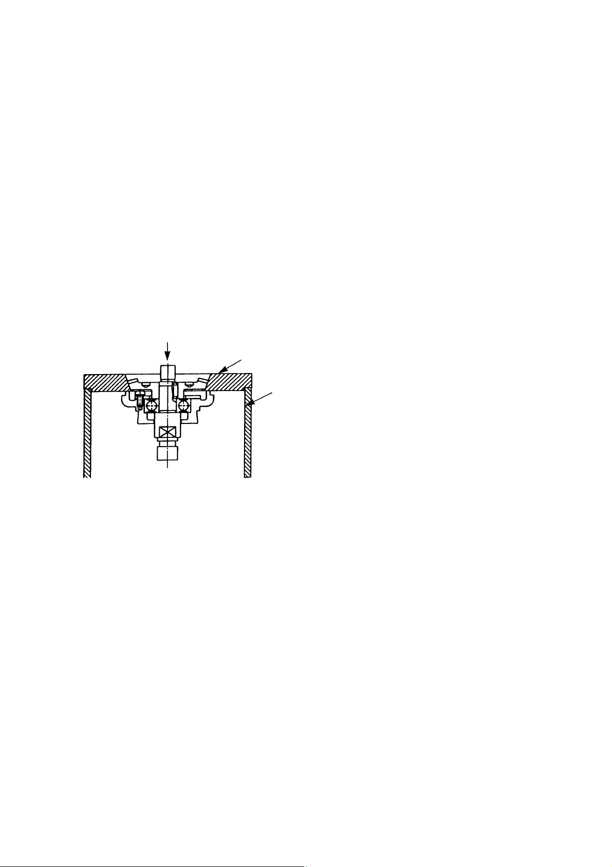
(8) For the models indicated under Fig. 4, the Ball Bearing
by utilizing a J-204 Bearing Puller (special repair t ool, Code No. 970982) as illustrated. After the Ball
Bearing has been removed, the Bearing Cover
[12]
[9]
can be removed from the Armature
can be easily taken off.
Bearing Puller (Code No. 970982)
[13]
Fig. 4
−
−#
1
Page 2
1-2. Disassembly of the Stator Ass’y:
(1) After removing the Armature Ass’y
the Brush Holders
[55]
.
and Switch Box
[13]
(2) Loosen the two D4 x 70L Hex. Hd. Tapping Screws
Housing
can be facilitated by heating the Housing
. If the Stator Ass’y
[43]
cannot be easily removed from the Housing
[16]
[43]
an appropriate heating device.
1-3. Disassembly of the Gear:
(1) Loosen the four M5 x 16L Seal Lock Screws
the Spindle
(2) When it is necessary to remove the Gear
, and Gear
[30]
from the Gear Cover Ass’y
[21]
[21]
the special repair tools described below be utilized.
Push
J-129-2
Gear Puller
J-130
Sleeve
, disconnect the lead wires connected to
[46]
and remove the Stator Ass’y
[15]
[43]
from the
[16]
, disassembly
to a temperature of approximately 60°C (140°F) with
, and remove the Packing Gland
[28]
in a single body.
[4]
from the Spindle
, it is highly recommended that
[30]
together with
[27]
As illustrated in Fig. 5, support the angled surface
of the Gear
with a J-129-2 Gear Puller
[21]
(special repair tool, Code No. 970906), rest the
J-129-2 Gear Puller on a J-130 Sleeve (special
repair tool, Code No. 970907), and push down on
the tip of the Spindle
remove the Gear
[21]
with a hand press to
[30]
.
Fig. 5
1-4. Reassembly:
Reassembly can be accomplished by following the disassembly procedures in reverse. However,
special attention should be given to the following items.
(1) After disassembly, thoroughly remove old grease from the inside of the Gear Cover Ass’y
[4]
insert 18 g of new grease (Nippeco JF-375, Code No. 930036, is recommended) prior to
reassembly. When inserting grease, apply it to the Pinion Gear tooth surfaces, and to the Needle
Bearing inside the Gear Cover.
(2) When replacing the Ball Bearing on the commutator side of the Armature, be very careful to ensure
that the Dust Seal (A)
is assembled in the proper direction. The Dust Seal (A)
[18]
[18]
plays an
important role in dustproofing of the Ball Bearing, and must be replaced with a new one if
disassembled. Do not forget to insert the Thrust Washer
(A)
[18]
.
on the Armature side of the Dust Seal
[17]
(3) Apply Three Bond TB 1406 Screw Locking Agent to the following screws.
, and
Three M4 x 10 Seal Lock Screws
Three M4 x 8 Seal Lock Screws
Four M5 x 16 Seal Lock Screws
which fix Bearing Cover
[1]
which fix Bearing Cover (B)
[22]
which fix Packing Gland
[28]
−#2 −
[12]
[27]
in place.
in place.
[23]
in place.
Page 3

1-5. Tightening Torque of Each Screw:
D3 Tapping Screw
D4 Tapping Screw (W/Flange)
...........................................0.74 ± 0.15 N
[56]
[50] [53] [60]
and D4 Hex. Hd. Tapping Screw
.................................................................................1.96 ± 0.49 N
D5 Tapping Screw
M4 Seal Lock Screw (W/Sp. Washer)
M5 Seal Lock Screw (W/Sp. Washer)
M7 Special Nut
.............................................2.94 ± 0.49 N
[2]
[1] [22]
[28]
..................................................5.88 ± 0.98 N
[5]
.......1.76 ± 0.39 N
.............3.43 ± 0.96 N
⋅⋅⋅⋅
m (7.5 ± 1.5kgf-cm,0.5 ± 0.4 ft-lb)
[15]
⋅⋅⋅⋅
m (20 ± 5kgf-cm, 1.4 ± 0.4 ft-lb)
⋅⋅⋅⋅
m (30 ± 5kgf-cm, 2.2 ± 0.4 ft-lb)
⋅⋅⋅⋅
m (18 ± 4kgf-cm, 1.3 ± 0.3 ft-lb)
⋅⋅⋅⋅
m (35 ± 7kgf-cm, 2.5 ± 0.5 ft-lb)
⋅⋅⋅⋅
m (60 ± 10kgf-cm, 3.6 ± 0.7 ft-lb)
−#3 −
Page 4

1-6. Wiring Diagrams
For European countries
Stator
[16]
Noise
Suppressor
For Asian countries (except Singapore)
Stator
[16]
Pillar Terminal
[52]
BlueBlue
[47]
Black Brown
Pillar Terminal
1 2
Switch
[59]
[52]
BlueBlue
Cord
Cord
[64]
[64]
Black Brown
For New Zealand
Stator
[16]
Noise
Suppressor
[47]
Black Brown
For U.S.A., Canada, Australia and Si ngapor e
Stator
[16]
White or Brown
1 2
Switch
Connector
1 2
Switch
Connector
White or
Blue
[59]
[51]
BlueBlue
[59]
[51]
Cord
[64]
Yellow or
Black
−#4 −
1 2
Switch
Black or
Brown
[59]
Cord
[64]
Page 5

1-7. Insulation Tests:
On completion of disassembly and repair, measure the insulation resistance and dielectric strength.
Insulation Resistance: 7 MΩ or more with DC 500 V Megohm Tester.
Dielectric Strength: AC 4000 V for 1 minute, with no abnormalities........220 V - 240 V
(and 110 V for U. K. products)
AC 2500 V for 1 minute, with no abnormalities........110 V -127 V
(except U. K. products)
1-8. Gear Backlash Value:
Gear backlash should be maintained at a value of 2 mm or less measured at the outer edge of a fresh
Depressed-Center Wheel.
1-9. No-Load Current Value:
After no-load operation for 30 minutes, the no-load current value should be as follows:
Voltage
Current (A) Max.
110 V 115 V 220 V 230 V 240 V
3 A 2.5 A 1.5 A 1.5 A 1.5 A
−#5 −
Page 6

2. STANDARD REPAIR TIME (UNIT) SCHEDULES
Model 10 20 30 40 50 60
G 12SE
G 13SE
Variable
Fixed
General
Assembly
Fixed Costs
Switch
Wheel
Guard
Tail
Cover (A)
Tail
Cover (B)
Cord
10 min.
Other
20 min.
Work Flow
0
min.
Wheel Guard
Ass’y
Tail Cover (A)
Tail Cover (B)
Carbon Brush
x 2 pcs.
Spring x 2 pcs.
Switch
Cord
Cord Armor
Paddle Lever
Lock Lever
Spring
Spring (F)
Pinion
Armature Ass’y
Gear Cover
Seal Ring (A)
Washer (C)
Ball Bearing
(629T12)
Rubber Ring
Felt
Bearing Cover
Dust Seal (A)
Ball Bearing
(608VVMC2)
Pushing Button
Lock Pin
Gear
Seal Packing
Switch Box
Rubber Ring
Brush Holder
x 2 pcs.
Housing
Stator
Bearing
Cover (B)
Ball Bearing
(6201DD)
Felt Packing
Packing Gland
Spindle
Key (3 x 3 x 8)
−#6 −
 Loading...