

Page 1
DISC GRINDER
MODELS
G 10SR2
G 12SR2
G 13SR2
POWER TOOLS
G 10SR2
G 12SR2
G 13SR2
TECHNICAL DATA
AND
SERVICE MANUAL
G
LIST Nos. G 10SR2: E260
G 12SR2: E261
G 13SR2: E262
SPECIFICATIONS AND PARTS ARE SUBJECT TO CHANGE FOR IMPROVEMENT
Feb. 2003
Page 2

REMARK:
Throughout this TECHNICAL DATA AND SERVICE MANUAL, a symbol(s)
is(are) used in the place of company name(s) and model name(s) of our
competitor(s). The symbol(s) utilized here is(are) as follows:
G 10SR2
Competitor
Symbols Utilized
Company Name
Model Name
G 12SR2
Symbols Utilized
G 13SR2
Symbols Utilized
C
B
C
B
MAKITA
BOSCH
Company Name
MAKITA
BOSCH
Company Name
9523NB
GWS6-100
Competitor
Model Name
9524NB
GWS6-115
Competitor
Model Name
C
MAKITA
9525NB
Page 3

CONTENTS
1. PRODUCT NAME...........................................................................................................................1
2. MARKETING OBJECTIVE .............................................................................................................1
3. APPLICA TIONS..............................................................................................................................1
4. SELLING POINTS ..........................................................................................................................1
5. SPECIFICATIONS ..........................................................................................................................2
6. COMPARISONS WITH SIMILAR PRODUCTS ..............................................................................4
6-1. Specification Comparisons ............................................................................................................ 4
6-2. Practical Test Data ......................................................................................................................... 5
7. PRECAUTIONS IN SALES PROMOTION .....................................................................................6
7-1. Handling Instructions ..................................................................................................................... 6
7-2. Caution on Name Plate.................................................................................................................. 6
Page
7-3. Precautions on Usage ................................................................................................................... 7
8. PRECAUTIONS IN DISASSEMBLY AND REASSEMBLY ............................................................8
8-1. Disassembly .................................................................................................................................. 8
8-2. Reassembly ................................................................................................................................... 9
8-3. Lubrication Points and Types of Lubricant................................................................................... 10
8-4. Tightening Torque .........................................................................................................................11
8-5. Wiring Diagrams ...........................................................................................................................11
8-6. Insulation Tests ............................................................................................................................ 12
8-7. No-Load Current Value ................................................................................................................ 12
9. STANDARD REPAIR TIME (UNIT) SCHEDULES .......................................................................13
Assembly Diagram for G 10SR2
Assembly Diagram for G 12SR2
Assembly Diagram for G 13SR2
Page 4
1. PRODUCT NAME
Hitachi Disc Grinders, Models G 10SR2 [100 mm (4")]
G 12SR2 [115 mm (4-1/2")]
G 13SR2 [125 mm (5")]
2. MARKETING OBJECTIVE
The Models G 10SR2, G 12SR2, and G 13SR2 are upgraded versions of the previous low-price G 10SR series,
developed under the concept for more powerful, convenient and competitively priced models to expand our
market share and sales. The key features of the Models G 10SR2, G 12SR2, and G 13SR2 in comparison with
the previous models are as follows:
1) Increased input and maximum output
2) Increased overload durability
3) Compact and lightweight, and easy-to-use slide switch
4) Low operating noise
5) Prolonged service life of the carbon brushes
3. APPLICA TIONS
Removal of casting fin and finishing of various types of steel, bronze, aluminum and various other metallic
•
materials
Grinding of welds, or sections cut by means of a cutting torch
•
Grinding of synthetic resins, slate, brick, marble, etc.
•
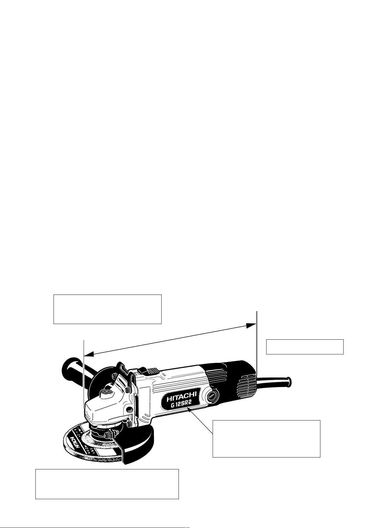
4. SELLING POINTS
Compact body: 254 mm (10")
Maker B's model: 256 (10-1/8")
Maker C's model: 263 (10-5/16")
254 mm (10")
Easy-to-use slide switch
Excellent overload durability:
1.20 times higher compared to maker B's model
1.02 times higher compared to maker C's model
High-power motor
(with maximum output of 1,010 W)
Maker B's model: 700 W
Maker C's model: 750 W
--- 1 ---
Page 5
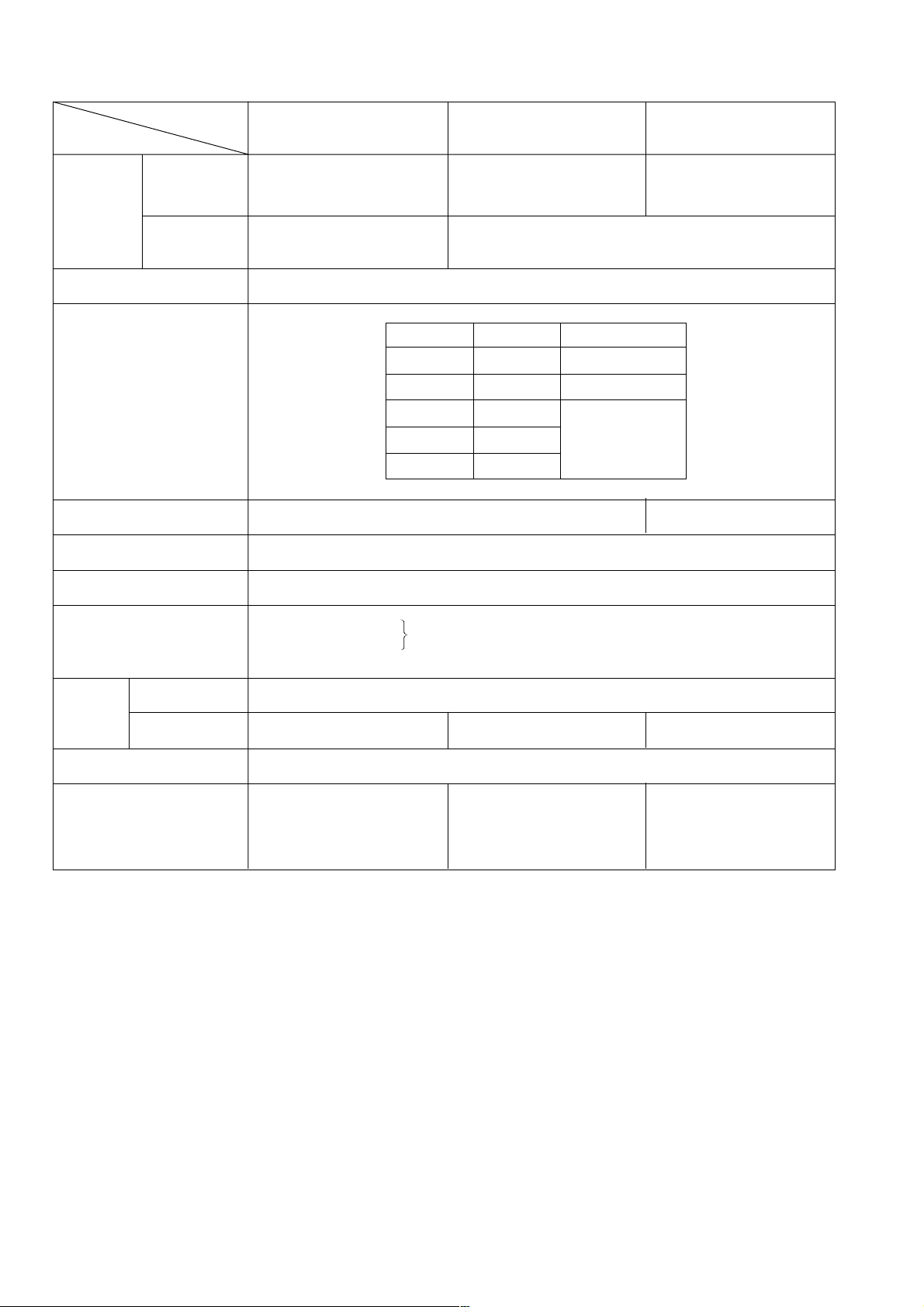
5. SPECIFICATIONS
Item
Depressed
Dimensions
center
wheel
Max. practical
peripheral speed
Voltage, current and
power input
Type of motor
Model
G 10SR2
O.D. 100 mm (4")
x Thickness 4 mm (5/32")
x I.D. 16 mm (5/8")
O.D. 115 mm (4-1/2")
x Thickness 6 mm (1/4")
x I.D. 22 mm (7/8")
4,300 m/min.
(14,100 ft/min, 72 m/s)
AC single phase 50 or 60 HzPower source
Voltage (V)
Current (A)
110
120
220 3.0
230 2.9
240 2.8
11,000 /min.No-load speed
AC single phase commutator motor
G 12SR2 G 13SR2
O.D. 125 mm (5")
x Thickness 6 mm (1/4")
x I.D. 22 mm (7/8")
4,800 m/min.
(15,756 ft/min, 80 m/s)
Power input (W)
6.1
5.0
650
580
650
10,000 /min.
Slide switchType of switch
Enclosure
1
Material: Housing
Tail cover
Gear cover, inner cover, packing gland
•••••
Glassfiber reinforced polyamide resin (green)
•••••
aluminum alloy die casting
1.4 kg (3.1 lbs.)Net *
Weight
2.2 kg (4.9 lbs.)Gross
2.4 kg (5.3 lbs.) 2.5 kg (5.5 lbs.)
Corrugated cardboard boxPackaging
Depressed center wheel
Standard accessories *
*1) Net weight excludes cord, side handle, depressed center wheel, wheel nut, wheel washer and wheel guard.
*2) Standard accessories may vary depending on market area.
2
100 mm (4")
Side handle
Wrench
••••••••••••••••
•••••••••••••••••
•••••••••••••••••••••••
Depressed center wheel
1
115 mm (4-1/2")
1
Side handle
1
Wrench
•••••••••••••••••
•••••••••••••••••••••••
•••••••••••
Depressed center wheel
125 mm (5")
1
Side handle
1
1
Wrench
•••••••••••••••••••••••
••••••••••••••••
•••••••••••••••••
1
1
1
--- 2 ---
Page 6
High-power motor
The Models G 10SR2, G 12SR2 and G 13SR2 are equipped with high-power motors and are more powerful
than the current Models G 10SR, G 12SR and G 13SR although they are compact and lightweight. We could
say that the ratio of the motor's maximum output to the product's weight defines its performance. Compared
with a typical competitor's model in terms of this indicator, the Models G 10SR2, G 12SR2 and G 13SR2 prove
to have the highest performance.
Table 1 Comparison of max. output and product weight
Maker
Model
Item
Max. output *
Actual product weight *
1
(W)
2
Max. output/product weight
(kg)
(W/kg)
G 10SR2/
G 12SR2/
G 13SR2
1,010
1.5 (3.3 lbs.)
673 (306 W/lbs.)
HITACHI
1.6 (3.5 lbs.)
525 (240 W/lbs.)
G 10SR/
G 12SR/
G 13SR
840
CB
700
1.5 (3.3 lbs.)
467 (212 W/lbs.)
750
1.4 (3.1 lbs.)
536 (241 W/lbs.)
*1 Depends on the market.
*2 Actual product weight excludes cord, side handle, depressed center wheel, wheel nut, wheel washer and wheel
guard.
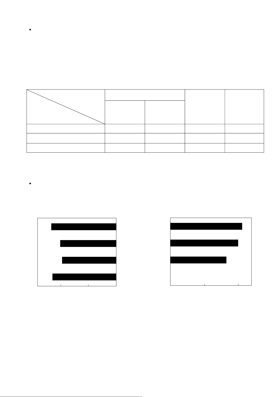
Excellent overload durability
The Models G 10SR2, G 12SR2 and G 13SR2 provide excellent overload durability thanks to an improved
cooling mechanism and a high-power motor.
Practical test data: Comparison of torque when the stator coil temperature rise is 200˚K
116
G 10SR2/
G 12SR2
G 13SR2
106
114
100
97
100
Fig. 1
50
G 10SR/
G 12SR
C
B
0
G 13SR
C
050
Fig. 2
100
82
100
--- 3 ---
Page 7
6. COMPARISONS WITH SIMILAR PRODUCTS
6-1. Specification Comparisons
Maker HITACHI
Model
G 10SR2/
G 12SR2
G 13SR2
G 10SR/
G 12SR
G 13SR
C
B
W
W
W
hr
kg
100 (4")/
115 (4-1/2")
1,010
254 (10")
60 (2-3/8")
1.4 (3.1 Ibs.)
125 (5")
650
370
10,000 10,000 11,000 10,000 11,000
86
140
Wheel diameter
Power input *
Output *
Max. output *
No-load speed 11,000
No-load sound
pressure level
Service life of
carbon brushes *
Grip perimeter 200 (7-7/8")
Dimension
Weight *
(Actual weight) (1.5) (3.3 Ibs.)
1
3
mm
1
1
/min.
dB/A
2
mm
mm
L
H
mm
100 (4")/
115 (4-1/2")
11,000
207 (8-1/8")
261 (10-1/4")
60 (2-3/8")
1.6 (3.5 Ibs.)
(1.6) (3.5 Ibs.)
600
370
840
87
90
125 (5")
100 (4")/
115 (4-1/2")
125 (5")
100 (4")/
115 (4-1/2")
540 670
310
700
82 82
130 100
195 (7-11/16") 191 (7-1/2")
256 (10-1/8") 263 (10-5/16")
70 (2-3/4") 73 (2-7/8")
1.4 (3.1 Ibs.) 1.4 (3.1 Ibs.)
(1.5) (3.3 Ibs.) (1.4) (3.1 Ibs.)
340
750
L
H
Grip perimeter
*1 Depends on the market.
*2 Service life of carbon brushes in the continuous rated load test.
3
Weight excludes cord, side handle, depressed center wheel, wheel nut, wheel washer and wheel guard.
*
--- 4 ---
Page 8
6-2. Practical Test Data
G 13SR
C
G 13SR2
200
100
0
Load
Stator coil temp. rise (k)
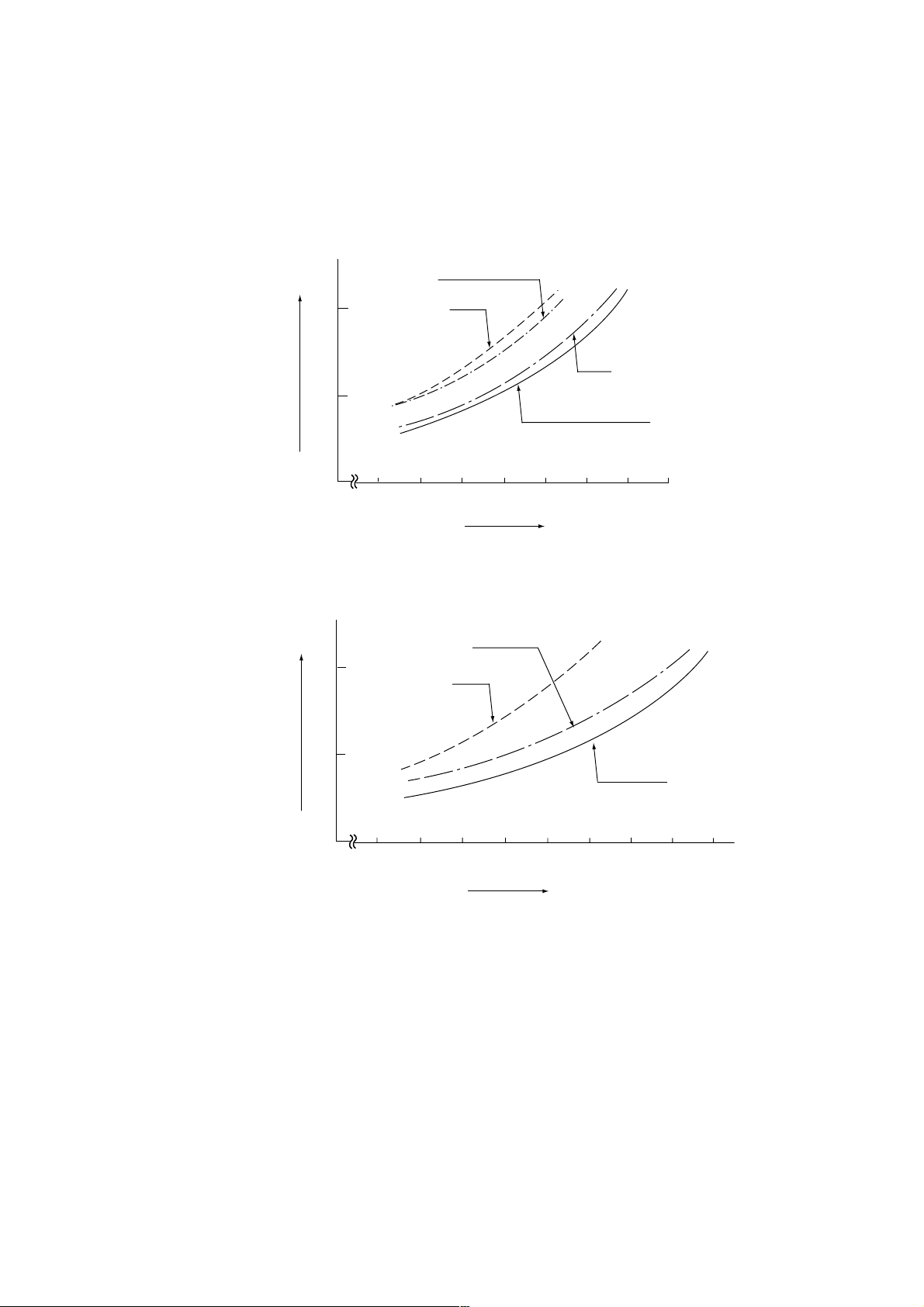
Comparison of temperature rise of stator coil section:
The graph below shows the relationship between load and temperature rise of stator coil. The temperature rise of
the Models G 10SR2, G 12SR2 and G 13SR2 is the lowest among similar models. This means that the
resistance to overload usage of the Models G 10SR2, G 12SR2 and G 13SR2 is superior to other models.
G 10SR/G 12SR
200
100
Stator coil temp. rise (k)
0
C
B
G 10SR2/G 12SR2
Load
Fig. 3
Fig. 4
--- 5 ---
Page 9
7. PRECAUTIONS IN SALES PROMOTION
In the interest of promoting the safest and most efficient use of the Models G 10SR2, G 12SR2 and G 13SR2 Disc
Grinders by all of our customers, it is very important that at the time of sale, the salesperson carefully ensures that
the buyer seriously recognizes the importance of the contents of the Handling Instructions, and fully understands
the meaning of the precautions listed on the Name Plate or Caution Plate attached to each tool.
7-1. Handling Instructions
Although every effort is made in each step of design, manufacture and inspection to provide protection against
safety hazards, the dangers inherent in the use of any electric power tool cannot be completely eliminated.
Accordingly, general precautions and suggestions for the use of electric power tools, and specific precautions and
suggestions for the use of the disc grinders are listed in the Handling Instructions to enhance the safe and efficient
use of the tool by the customer. Salespersons must be thoroughly familiar with the contents of the Handling
Instructions to be able to offer appropriate guidance to the customer during sales promotion.
7-2. Caution on Name Plate
Each tool is provided with a Name Plate which contains the following basic safety precautions in the use of the
tool.
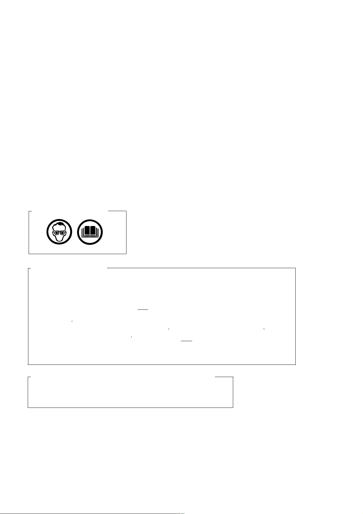
(1) For European countries
(2) For U.S.A. and Canada
WARNING
To reduce the risk of injury, user must read and understand instruction manual.
Always use proper guards when grinding and wear eye protection.
Use only accessories rated at least * /min.
AVERTISSEMENT
Afin de reduire le risque de blessures, I'utilisateur doit lire et bien comprendre le mode d'emploi.
Utilisez toujours un outil muni d'un protecteur adequat et portez des lunettes on une visiere.
N'utilisez que des accessoires prevus pour au moins * /min.
* G 10SR2: 13,700
G 12SR2: 13,300
G 13SR2: 12,000
(3) For The People's Republic of China, New Zealand and Australia
CAUTION
Read thoroughly HANDLING INSTRUCTIONS before use.
--- 6 ---
Page 10

7-3. Precautions on Usage
(1) The wheel guard must be aligned in relation to the side handle mounting position.
As illustrated in Figs. 5 and 6, the customer should be instructed that the wheel guard mounting angle must be
aligned and fixed in accordance with the side handle mounting position so that the operator's hand will not
contact the depressed center wheel.
ON
OFF
0
ON
OFF 0
Fig. 5 Fig. 6
(2) Never press the pushing button while the depressed center wheel is rotating.
If the pushing button is pressed while the depressed center wheel is rotating, the spindle will stop immediately.
In such a case, there is a danger that the wheel nut may be loosened so that the depressed center wheel flies
off unexpectedly to cause possible serious injury.
--- 7 ---
Page 11

8. PRECAUTIONS IN DISASSEMBLY AND REASSEMBLY
The [Bold] numbers in the descriptions below correspond to the numbers in the Parts Lists and exploded
assembly diagram for the Models G 10SR2, G 12SR2 and G 13SR2.
8-1. Disassembly
(1) Replacement of the Armature and Stator
Remove the Brush Caps [47] and take off the Carbon Brushes [48].
Loosen the four Tapping Screws D5 x 25 (Black) [1] which fix the Gear Cover Ass'y [4], and take off the
Inner Cover [9] together with the Armature [10] from the Housing Ass'y [39].
At this time, make sure that the Rubber Bushing [16] is fitted in the housing ball bearing chamber. If the
rubber bushing comes off the housing ball bearing chamber or adheres to the Ball Bearing [15],
reassemble the disc grinder according to "8-2. Reassembly".
Loosen the two Tapping Screws (W/Flange) D4 x 45 [57] securing the Tail Cover [56] and remove the Tail
Cover [56].
Remove the four internal wires from the Stator [13] connected with the Brush Holder [49], the Pillar
Terminal [45] and the Switch [50].
Loosen the two Hex. Hd. Tapping Screws D4 x 65 [12] securing the Stator [13] and remove the Stator [13]
from the Housing Ass'y [39]. If you have any trouble with removing the Stator [13], heat the Housing Ass'y
[39] to about 60˚C for easier dismantling.
(2) Replacement of the rubber bushing
Insert the J-201 Spring Hook H-75 (Special Repair Tool) between the Rubber Bushing [16] assembled in
the Housing Ass'y [39] and the housing ball bearing chamber and pull out the Rubber Bushing [16].
(3) Replacement of the Dust Seal
Insert the hooks of the J-204 Bearing Puller (Special Repair Tool, Code No. 970982) between the Ball
Bearing [15] and the Dust Seal [14] and fix the hooks with the wing bolts. Be careful not to insert the hook
too much.
Put the bearing puller on an appropriate stand. Push down the armature shaft with a hand press and pull
out the Ball Bearing [15].
Pull out the Dust Seal [14] from the armature shaft.
(4) Disassembly of the gear
Loosen the four Seal Lock Screws (W/Sp. Washer) M4 x 12 [26] that secure the Packing Gland [25] to the
Gear Cover Ass'y [4] and remove the Packing Gland [25] from the Gear Cover Ass'y [4].
Remove the Retaining Ring for D11 Shaft [18] that secures the Gear [20] to the Spindle [28].
Remove the Wave Washer [19] and the Gear [20] from the Spindle [28].
--- 8 ---
Page 12

8-2. Reassembly
Put the parts together in the reverse order of disassembly, with the precautions given below.
(1) Generously lubricate the teeth of Gear [20] and Pinion [6] with grease. Rub grease onto the teeth with your
fingers so that the grease reaches each tooth bottom. Note that the Gear [20] and the Pinion [6] may wear at
a faster rate if under-lubricated.
(2) Be sure to soak the inner diameter of the Felt Packing [24] with machine oil. Otherwise, its dust-sealing
function will fail to work properly, resulting in an earlier damage of the Ball Bearing [23].
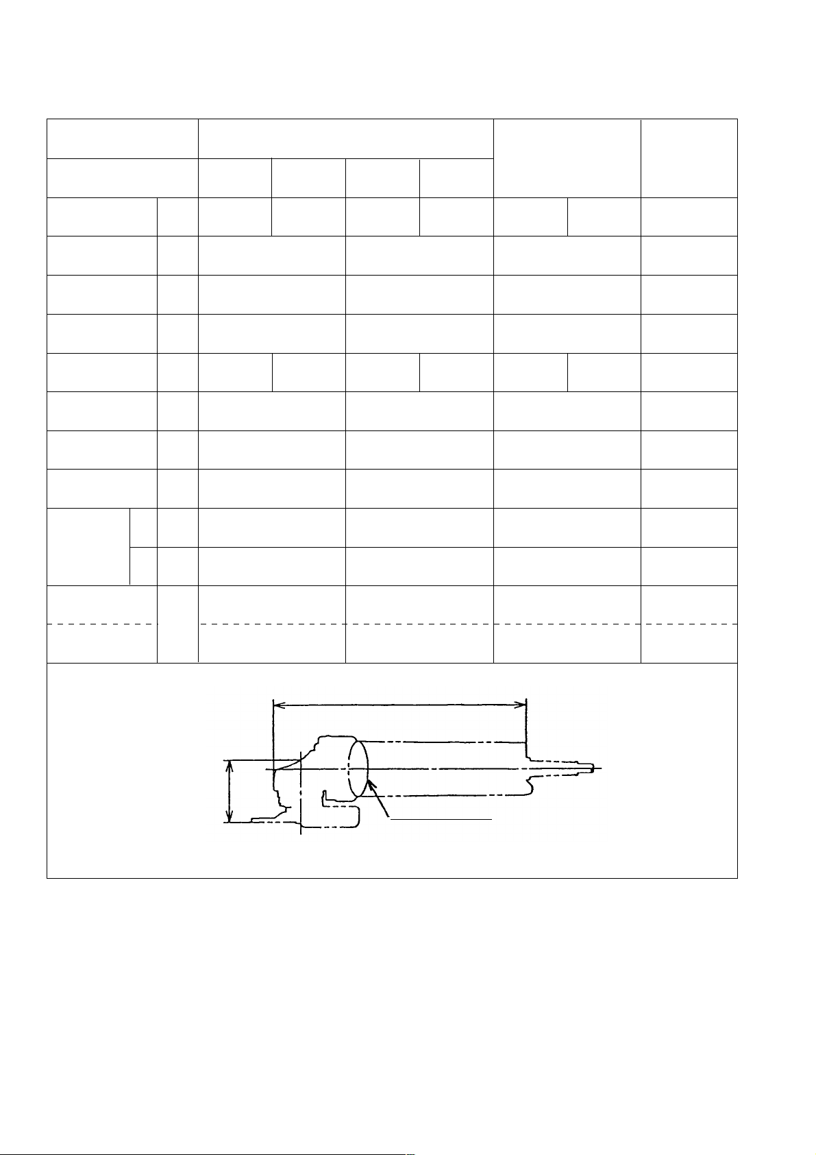
(3) When replacing the Armature [10] and the Ball Bearing [15] on the commutator side, press inward on the Dust
Seal [14] while taking care of its direction until the end face of the Dust Seal [14] hits against the a butting
surface of the Armature [10] and make sure that Dust Seal [14] cannot turn freely. Keep the end face of the
armature shaft approximately 0.2 mm (reference) distance inward of the end face of the Ball Bearing [15].
(See Fig. 7.)
The Dust Seal [14] is an important element for improved dust protection of the Ball Bearing [15]. Be sure to
use a new one upon replacement.
Fit the Rubber Bushing [16] into the housing ball bearing chamber before installing the Armature [10].
(See Fig. 8.)
About 0.2 mm (reference)
Dust Seal [14]
Fig. 7
Housing ball bearing chamber
Rubber Bushing [16]
Armature shaft
Ball Bearing [15]
About 4.5 mm
Fig. 8
--- 9 ---
Page 13

(4) When installing the Stator [13] into the Housing Ass'y [39], insert it while taking care of the placement of the
internal wires of the Stator [13] as indicated in Fig. 9.
Connect the four internal wires of Stator [13] with the parts indicated in Fig. 9.
Connect to the Brush Holder [49]
(on the same side as the Name
Plate [40]).
Connect to the Cord [58] with a
Pillar Terminal [45].
Connect to the Brush Holder
[49] (on the same side as the
Hitachi Label [46]).
Connect to the Switch [50].
(When using the Noise Suppressor [43],
connect to the Switch [50] with the Terminal
[42] of the Noise Suppressor [43].)
Fig. 9
(5) When connecting the Earth Terminal [41] to the internal wire (the middle wire among three) of the Noise
Suppressor [43], strip the insulation sheath on the internal wire by about 6 mm and press-connect it together
with the Earth Terminal [41] with a clamping tool on the market.
Solderless connection
Fig. 10
(6) When replacing the Gear Cover Ass'y [4], lubricate the metal part with mixed oil.
Mixed oil: Mixture of Hitachi power tool grease No. 2 (Unilube No. 00) and turbine oil
Mixture ratio
•••
1:1 (weight ratio) Volume
•••
0.5 cc
8-3. Lubrication Points and Types of Lubricant
Pinion chamber of Gear Cover Ass'y [4]
••••••••••••••
Nippeko grease (SEP-3A) 10 g
Metal
••••••••••••••••••••••••••••••••••••••••••••••••••••••••••• ••••
Generously rub grease onto the gear and pinion.
Mixed oil 0.5 cc
Mixed oil: Mixture of Hitachi power tool grease No. 2
(Unilube No. 00) and turbine oil
Mixture ratio
••••••
1:1 (weight ratio)
--- 10 ---
Page 14

8-4. Tightening Torque
Tapping Screw D4 [12] [54] [57]
••••••••••••••••••••••••••••••••••••••••
Slotted Hd. Screw (Seal Lock) M4 x 10 [7]
Seal Lock Screw (W/Sp. Washer) M4 [21] [26]
Tapping Screw D5 x 25 [1]
••••••••••••••••••••••••••••••••••••••••••••••••••
Machine Screw (W/Sp. Washer) M5 x 16 [29]
Special Nut M6 [5]
Brush Cap [47]
•••••••••••••••••••••••••••••••••••••••••••••••••••••••••••••
••••••••••••••••••••••••••••••••••••••••••••••••••••••••••••••••••
8-5. Wiring Diagrams
For U.S.A., Canada, U.A.E. and India
••••••••••••••••••••••••••
••••••••••••••••••••
••••••••••••••••••••••
2.0 0.5 N•m (20 5 kgf•cm, 1.5 0.4 ft-lbs.)
1.8 0.4 N•m (18 4 kgf•cm, 1.3 0.3 ft-lbs.)
1.8 0.5 N•m (18 4 kgf•cm, 1.3 0.3 ft-lbs.)
2.9 0.5 N•m (30 5 kgf•cm, 2.2 0.4 ft-lbs.)
3.4 0.7 N•m (35 7 kgf•cm, 2.5 0.5 ft-lbs.)
4.9 1.0 N•m (50 10 kgf•cm, 3.6 0.7 ft-lbs.)
1.0 0.5 N•m (10 5 kgf•cm, 0.7 0.4 ft-lbs.)
For other countries
Yellow
Yellow
Yellow
Stator [13]
Stator [13]
Yellow
Yellow
Yellow
Switch [50]
Brown
or
Black
Blue
or
White
Pillar Terminal [45]
Switch [50]
Cord [58]
Yellow
Yellow
--- 11 ---
Brown
or
Black
Blue
or
White
Pillar Terminal [45]
Cord [58]
Page 15

8-6. Insulation Tests
On completion of disassembly and repair, measure the insulation resistance and conduct the dielectric strength
test.
Insulation resistance: 7 M or more with DC 500 V Megohm Tester
Dielectric strength: AC 4,000 V/1 minute, with no abnormalities
AC 2,500 V/1 minute, with no abnormalities
••••••••••••••
••••••••••••••
220 V --- 240 V
110 V --- 127 V
8-7. No-Load Current Value
After no-load operation for 30 minutes, the no-load current value should be as follows:
Voltage
Current (A) max.
110 V 120 V
3.5 3.3
220 V
1.9
230 V
2.0
240 V
1.8
--- 12 ---
Page 16

9. STANDARD REPAIR TIME (UNIT) SCHEDULES
MODEL 10 20 30 40 50 60 min.
Fixed
Variable
Work Flow
G 10SR2
G 12SR2
G 13SR2
General Assembly
Switch
Tail Cover
Cord
Cord Armor
Housing Ass'y
Stator
Slide Bar
Spring
Slide Knob
Armature
Pinion
Ball Bearing
(608VV)
Inner Cover
Dust Seal
Ball Bearing
(626VV)
Rubber Bushing
Gear Cover
Ass'y
Pushing Button
Lock Pin
Gear
Packing Gland
Ball Bearing
(6001VV)
Spindle
Gear and
Pinion Ass'y
Wheel Guard
Ass'y
--- 13 ---
Page 17

LIST NO.
ELECTRIC TOOL PARTS LIST
E260
DISC GRINDER
Model G 10SR2
1
2
3
4
5
17
18
19
20
21
22
35
2003 • 2 •5
(E1)
6
7
8
9
10
11
12
13
14
15
16
23
24
25
26
27
28
31
32
33
34
29
30
36
37
56
46
47
38
48
57
39
50
49
51
40
58
52
41
53
54
42
43
44
45
55
501
502
Page 18

PARTS
ITEM
NO.
CODE NO.
DESCRIPTION REMARKS
1 320-523 TAPPING SCREW D5X25 (BLACK) 4
2 302-149 GUARD PLATE 1
3 301-944 PUSHING BUTTON 1
4 314-125 GEAR COVER ASS’Y 1 INCLUD. 3, 17
5 309-191 SPECIAL NUT M6 1
6 321-724 PINION 1
7 314-430
SLOTTED HD. SCREW (SEAL LOCK) M4X10
8 608-VVM BALL BEARING 608VVC2PS2L 1
9 301-935 INNER COVER 1
* 10 360-605C ARMATURE 110V 1
* 10 360-605U ARMATURE ASS’Y 120V 1 INCLUD. 8, 14, 15
* 10 360-605E ARMATURE 220V-240V 1
11 306-840 FAN GUIDE 1
12 963-712 HEX. HD. TAPPING SCREW D4X65 2
* 13 340-552C STATOR 110V 1
* 13 340-552D STATOR 120V 1
* 13 340-552E STATOR 220V-230V 1
* 13 340-552F STATOR 240V 1
14 321-722 DUST SEAL 1
15 626-VVM BALL BEARING 626VVC2PS2L 1
16 309-929 RUBBER BUSHING 1
17 301-943 LOCK PIN 1
18 316-487 RETAINING RING FOR D11 SHAFT 1
19 316-486 WAVE WASHER 1
20 321-725 GEAR 1
21 987-201
SEAL LOCK SCREW (W/SP. WASHER) M4X10 3
22 938-058 BEARING COVER (B) 1
23 600-1VV BALL BEARING 6001VVCMPS2L 1
24 301-946 FELT PACKING 1
25 301-947 PACKING GLAND 1
26 987-203
SEAL LOCK SCREW (W/SP. WASHER) M4X12 4
27 302-047 WOODRUFF KEY 1
* 28 321-727 SPINDLE M10X1.5 1
* 28 321-728 SPINDLE M10X1.25 1 FOR USA, CAN
29 308-386
MACHINE SCREW (W/SP. WASHER) M5X16 (BLACK)
30 301-949 SET PLATE 1
31 301-948 WHEEL GUARD ASS’Y 1 INCLUD. 29, 30
* 32 320-497 WHEEL WASHER 1
* 32 937-834Z WHEEL WASHER 1 FOR USA, CAN
* 33 316-820 D. C. WHEELS 100MMX4T A36Q (25 PCS.) 1 EXCEPT FOR GBR, CHN
* 34 321-795 WHEEL NUT (C) 1
* 34 312-048 WHEEL NUT M10XP1.25 1 FOR USA, CAN
35 321-723 GEAR AND PINION ASS’Y 1 INCLUD. 6, 20
36 314-429 SPRING 1
37 314-427 SLIDE BAR 1
38 314-428 SLIDE KNOB 1
39 321-721 HOUSING ASS’Y 1 INCLUD. 16
* 40 NAME PLATE 1
* 41 314-854 EARTH TERMINAL 1 FOR NOISE SUPPRESSOR
* 42 980-063 TERMINAL 1 FOR NOISE SUPPRESSOR
* 43 994-273 NOISE SUPPRESSOR 1 EXCEPT FOR USA, CAN, IND
--- 2 ---
ALTERNATIVE PARTS
*
NO.
USED
2
2
G 10SR2
2 -- 03
Page 19

PARTS
ITEM
NO.
CODE NO.
DESCRIPTION REMARKS
44 314-432 SWITCH HOLDER 1
45 938-307 PILLAR TERMINAL 1
46 HITACHI LABEL 1
47 936-551 BRUSH CAP 2
48 999-021 CARBON BRUSH (1 PAIR) 2
49 313-777 BRUSH HOLDER 2
50 314-603 SWITCH (1P SOLDER TYPE) 1 INCLUD. 51
51 305-499 MACHINE SCREW (W/WASHER) M3.5X6 2
* 52 980-063 TERMINAL 1 FOR CORD
53 937-631 CORD CLIP 1
54 984-750 TAPPING SCREW (W/FLANGE) D4X16 2
55 953-327 CORD ARMOR D8.8 1
56 321-726 TAIL COVER 1
57 301-815 TAPPING SCREW (W/FLANGE) D4X45 2
* 58 500-409Z CORD 1 (CORD ARMOR D8.8)
* 58 500-439Z CORD 1 (CORD ARMOR D8.8) FOR AUS, NZL
* 58 500-461Z CORD 1 (CORD ARMOR D8.8) FOR GBR (110V)
* 58 500-435Z CORD 1 (CORD ARMOR D8.8) FOR GBR (230V)
* 58 500-240Z CORD 1 (CORD ARMOR D8.8) FOR USA, CAN
NO.
USED
G 10SR2
2 -- 03
ALTERNATIVE PARTS --- 3 ---
*
Page 20

STANDARD ACCESSORIES
ITEM
NO.
CODE NO.
DESCRIPTION REMARKS
501 313-933 WRENCH 1
* 502 302-142 SIDE HANDLE 1
* 502 318-312 SIDE HANDLE 1 FOR USA, CAN
NO.
USED
OPTIONAL ACCESSORIES
ITEM
NO.
CODE NO.
DESCRIPTION
601 314-051 SANDING DISCS 100MM C-P16 (10 PCS.) 1
602 314-052 SANDING DISCS 100MM C-P20 (10 PCS.) 1
603 314-053 SANDING DISCS 100MM C-P24 (10 PCS.) 1
604 314-054 SANDING DISCS 100MM C-P30 (10 PCS.) 1
605 314-055 SANDING DISCS 100MM C-P36 (10 PCS.) 1
606 314-056 SANDING DISCS 100MM C-P40 (10 PCS.) 1
607 314-057 SANDING DISCS 100MM C-P50 (10 PCS.) 1
608 314-058 SANDING DISCS 100MM C-P60 (10 PCS.) 1
609 314-059 SANDING DISCS 100MM C-P80 (10 PCS.) 1
610 314-060 SANDING DISCS 100MM C-P100 (10 PCS.) 1
611 314-061 SANDING DISCS 100MM C-P120 (10 PCS.) 1
* 612 935-513 WASHER NUT M10XP1.5 1
* 612 313-173 WASHER NUT M10XP1.25 1 FOR USA, CAN
613 936-548 WASHER 1
614 936-558Z RUBBER PAD 1
615 302-098 GUIDE BASE 1
616 986-381 DUST COLLECTOR (FOR DISC GRINDER) 1
NO.
USED
G 10SR2
REMARKS
--- 4 ---
ALTERNATIVE PARTS
*
Printed in Japan
(030205N)
2 -- 03
Page 21

LIST NO.
ELECTRIC TOOL PARTS LIST
E261
DISC GRINDER
Model G 12SR2
1
2
3
4
5
17
18
19
20
21
22
35
2003 • 2 •5
(E1)
6
7
8
9
10
11
12
13
14
15
16
23
24
25
26
27
28
31
32
33
34
29
30
36
37
56
46
47
38
48
57
39
49
50
51
40
58
52
41
53
54
42
43
44
45
55
501
502
503
Page 22

PARTS
ITEM
NO.
CODE NO.
DESCRIPTION REMARKS
1 320-523 TAPPING SCREW D5X25 (BLACK) 4
2 302-149 GUARD PLATE 1
3 301-944 PUSHING BUTTON 1
4 314-125 GEAR COVER ASS’Y 1 INCLUD. 3, 17
5 309-191 SPECIAL NUT M6 1
6 321-724 PINION 1
7 314-430
SLOTTED HD. SCREW (SEAL LOCK) M4X10 2
8 608-VVM BALL BEARING 608VVC2PS2L 1
9 301-935 INNER COVER 1
* 10 360-605C ARMATURE 110V 1
* 10 360-605U ARMATURE ASS’Y 120V 1 INCLUD. 8, 14, 15
* 10 360-605E ARMATURE 220V-240V 1
11 306-840 FAN GUIDE 1
12 963-712 HEX. HD. TAPPING SCREW D4X65 2
* 13 340-552C STATOR 110V 1
* 13 340-552D STATOR 120V 1
* 13 340-552E STATOR 220V-230V 1
* 13 340-552F STATOR 240V 1
14 321-722 DUST SEAL 1
15 626-VVM BALL BEARING 626VVC2PS2L 1
16 309-929 RUBBER BUSHING 1
17 301-943 LOCK PIN 1
18 316-487 RETAINING RING FOR D11 SHAFT 1
19 316-486 WAVE WASHER 1
20 321-725 GEAR 1
21 987-201
SEAL LOCK SCREW (W/SP. WASHER) M4X10 3
22 938-058 BEARING COVER (B) 1
23 600-1VV BALL BEARING 6001VVCMPS2L 1
24 301-946 FELT PACKING 1
25 301-947 PACKING GLAND 1
26 987-203
SEAL LOCK SCREW (W/SP. WASHER) M4X12
27 302-047 WOODRUFF KEY 1
* 28 321-729 SPINDLE M14 1
* 28 321-730 SPINDLE 5/8”-11UNC 1 FOR USA, CAN
29 308-386
MACHINE SCREW (W/SP. WASHER) M5X16 (BLACK)
30 301-949 SET PLATE 1
31 315-492 WHEEL GUARD ASS’Y 1 INCLUD. 29, 30
* 32 937-817Z WHEEL WASHER 1
* 32 319-373 WHEEL WASHER 1 FOR USA, CAN
* 33 316-821 D. C. WHEELS 115MM A36Q (25 PCS.) 1 FOR USA, CAN, NZL, AUS
* 34 994-324 WHEEL NUT M14 1
* 34 937-923P WHEEL NUT 5/8”-11UNC 1 FOR USA, CAN
35 321-723 GEAR AND PINION ASS’Y 1 INCLUD. 6, 20
36 314-429 SPRING 1
37 314-427 SLIDE BAR 1
38 314-428 SLIDE KNOB 1
39 321-721 HOUSING ASS’Y 1 INCLUD. 16
* 40 NAME PLATE 1
* 41 314-854 EARTH TERMINAL 1 FOR NOISE SUPPRESSOR
* 42 980-063 TERMINAL 1 FOR NOISE SUPPRESSOR
* 43 994-273 NOISE SUPPRESSOR 1 EXCEPT FOR USA, CAN, UAE
--- 2 ---
ALTERNATIVE PARTS
*
NO.
USED
4
2
G 12SR2
2 -- 03
Page 23

PARTS
ITEM
NO.
CODE NO.
DESCRIPTION REMARKS
44 314-432 SWITCH HOLDER 1
45 938-307 PILLAR TERMINAL 1
46 HITACHI LABEL 1
47 936-551 BRUSH CAP 2
48 999-021 CARBON BRUSH (1 PAIR) 2
49 313-777 BRUSH HOLDER 2
50 314-603 SWITCH (1P SOLDER TYPE) 1 INCLUD. 51
51 305-499 MACHINE SCREW (W/WASHER) M3.5X6 2
* 52 980-063 TERMINAL 1 FOR CORD
53 937-631 CORD CLIP 1
54 984-750 TAPPING SCREW (W/FLANGE) D4X16 2
55 953-327 CORD ARMOR D8.8 1
56 321-726 TAIL COVER 1
57 301-815 TAPPING SCREW (W/FLANGE) D4X45 2
* 58 500-409Z CORD 1 (CORD ARMOR D8.8)
* 58 500-423Z CORD 1 (CORD ARMOR D8.8) FOR UAE
* 58 500-439Z CORD 1 (CORD ARMOR D8.8) FOR NZL, AUS
* 58 500-461Z CORD 1 (CORD ARMOR D8.8) FOR GBR (110V)
* 58 500-435Z CORD 1 (CORD ARMOR D8.8) FOR GBR (230V)
* 58 500-447Z CORD 1 (CORD ARMOR D8.8) FOR SUI
* 58 500-240Z CORD 1 (CORD ARMOR D8.8) FOR USA, CAN
NO.
USED
G 12SR2
2 -- 03
ALTERNATIVE PARTS --- 3 ---
*
Page 24

STANDARD ACCESSORIES
ITEM
NO.
CODE NO.
DESCRIPTION REMARKS
501 938-332Z WRENCH 1
* 502 302-142 SIDE HANDLE 1
* 502 318-312 SIDE HANDLE 1 FOR USA, CAN
* 503 319-375 CASE 1 FOR USA, CAN, NZL, AUS
NO.
USED
OPTIONAL ACCESSORIES
ITEM
NO.
CODE NO.
DESCRIPTION
601 314-095 SANDING DISCS 115MM C-P16 (10 PCS.) 1
602 314-096 SANDING DISCS 115MM C-P20 (10 PCS.) 1
603 314-097 SANDING DISCS 115MM C-P24 (10 PCS.) 1
604 314-098 SANDING DISCS 115MM C-P30 (10 PCS.) 1
605 314-099 SANDING DISCS 115MM C-P36 (10 PCS.) 1
606 314-100 SANDING DISCS 115MM C-P40 (10 PCS.) 1
607 314-101 SANDING DISCS 115MM C-P50 (10 PCS.) 1
608 314-102 SANDING DISCS 115MM C-P60 (10 PCS.) 1
609 314-103 SANDING DISCS 115MM C-P80 (10 PCS.) 1
610 314-104 SANDING DISCS 115MM C-P100 (10 PCS.) 1
611 314-105 SANDING DISCS 115MM C-P120 (10 PCS.) 1
* 612 937-826Z WASHER NUT 1
* 612 938-318 WASHER NUT 1 FOR USA, CAN
* 613 937-825Z RUBBER PAD 1
* 613 938-317 RUBBER PAD 1 FOR USA, CAN
* 614 310-338 SUPER WASHER 1 EXCEPT FOR USA, CAN
NO.
USED
REMARKS
G 12SR2
--- 4 ---
ALTERNATIVE PARTS
*
Printed in Japan
(030205N)
2 -- 03
Page 25

LIST NO.
ELECTRIC TOOL PARTS LIST
E262
DISC GRINDER
Model G 13SR2
1
2
3
4
5
17
18
19
20
21
22
35
2003 • 2 •5
(E1)
6
7
8
9
10
11
12
13
14
15
16
23
24
25
26
27
28
31
32
33
34
29
30
36
37
56
46
47
38
48
57
39
49
50
40
51
58
52
41
53
54
42
43
44
45
55
501
502
Page 26

PARTS
ITEM
NO.
CODE NO.
DESCRIPTION REMARKS
1 320-523 TAPPING SCREW D5X25 (BLACK) 4
2 302-149 GUARD PLATE 1
3 301-944 PUSHING BUTTON 1
4 314-125 GEAR COVER ASS’Y 1 INCLUD. 3, 17
5 309-191 SPECIAL NUT M6 1
6 321-742 PINION 1
7 314-430
SLOTTED HD. SCREW (SEAL LOCK) M4X10
8 608-VVM BALL BEARING 608VVC2PS2L 1
9 301-935 INNER COVER 1
* 10 360-605U ARMATURE ASS’Y 120V 1 INCLUD. 8, 14, 15
* 10 360-605E ARMATURE 220V-240V 1
11 306-840 FAN GUIDE 1
12 963-712 HEX. HD. TAPPING SCREW D4X65 2
* 13 340-552D STATOR 120V 1
* 13 340-552E STATOR 220V-230V 1
14 321-722 DUST SEAL 1
15 626-VVM BALL BEARING 626VVC2PS2L 1
16 309-929 RUBBER BUSHING 1
17 301-943 LOCK PIN 1
18 316-487 RETAINING RING FOR D11 SHAFT 1
19 316-486 WAVE WASHER 1
20 321-743 GEAR 1
21 987-201
SEAL LOCK SCREW (W/SP. WASHER) M4X10 3
22 938-058 BEARING COVER (B) 1
23 600-1VV BALL BEARING 6001VVCMPS2L 1
24 301-946 FELT PACKING 1
25 301-947 PACKING GLAND 1
26 987-203
SEAL LOCK SCREW (W/SP. WASHER) M4X12 4
27 302-047 WOODRUFF KEY 1
* 28 321-729 SPINDLE M14 1
* 28 321-730 SPINDLE 5/8”-11UNC 1 FOR USA, CAN
29 308-386
MACHINE SCREW (W/SP. WASHER) M5X16 (BLACK)
30 301-949 SET PLATE 1
31 319-116 WHEEL GUARD ASS’Y 1 INCLUD. 29, 30
* 32 937-817Z WHEEL WASHER 1
* 32 319-373 WHEEL WASHER 1 FOR USA, CAN
* 33 316-822 D. C. WHEELS 125MM A36Q (25 PCS.) 1 FOR USA, CAN
* 34 994-324 WHEEL NUT M14 1
* 34 937-923P WHEEL NUT 5/8”-11UNC 1 FOR USA, CAN
35 321-741 GEAR AND PINION ASS’Y 1 INCLUD. 6, 20
36 314-429 SPRING 1
37 314-427 SLIDE BAR 1
38 314-428 SLIDE KNOB 1
39 321-721 HOUSING ASS’Y 1 INCLUD. 16
40 NAME PLATE 1
* 41 314-854 EARTH TERMINAL 1 FOR NOISE SUPPRESSOR
* 42 980-063 TERMINAL 1 FOR NOISE SUPPRESSOR
* 43 994-273 NOISE SUPPRESSOR 1 EXCEPT FOR USA, CAN
44 314-432 SWITCH HOLDER 1
45 938-307 PILLAR TERMINAL 1
46 HITACHI LABEL 1
--- 2 ---
ALTERNATIVE PARTS
*
NO.
USED
2
2
G 13SR2
2 -- 03
Page 27

PARTS
ITEM
NO.
CODE NO.
DESCRIPTION REMARKS
47 936-551 BRUSH CAP 2
48 999-021 CARBON BRUSH (1 PAIR) 2
49 313-777 BRUSH HOLDER 2
50 314-603 SWITCH (1P SOLDER TYPE) 1 INCLUD. 51
51 305-499 MACHINE SCREW (W/WASHER) M3.5X6 2
* 52 980-063 TERMINAL 1 FOR CORD
53 937-631 CORD CLIP 1
54 984-750 TAPPING SCREW (W/FLANGE) D4X16 2
55 953-327 CORD ARMOR D8.8 1
56 321-726 TAIL COVER 1
57 301-815 TAPPING SCREW (W/FLANGE) D4X45 2
* 58 500-409Z CORD 1 (CORD ARMOR D8.8)
* 58 500-240Z CORD 1 (CORD ARMOR D8.8) FOR USA, CAN
* 58 500-409Z CORD 1 (CORD ARMOR D8.8) FOR CHN
NO.
USED
G 13SR2
2 -- 03
ALTERNATIVE PARTS --- 3 ---
*
Page 28

STANDARD ACCESSORIES
ITEM
NO.
CODE NO.
DESCRIPTION REMARKS
501 938-332Z WRENCH 1
* 502 302-142 SIDE HANDLE 1
* 502 318-312 SIDE HANDLE 1 FOR USA, CAN
NO.
USED
OPTIONAL ACCESSORIES
ITEM
NO.
CODE NO.
DESCRIPTION
601 314-062 SANDING DISCS 125MM C-P16 (10 PCS.) 1
602 314-063 SANDING DISCS 125MM C-P20 (10 PCS.) 1
603 314-064 SANDING DISCS 125MM C-P24 (10 PCS.) 1
604 314-065 SANDING DISCS 125MM C-P30 (10 PCS.) 1
605 314-066 SANDING DISCS 125MM C-P36 (10 PCS.) 1
606 314-067 SANDING DISCS 125MM C-P40 (10 PCS.) 1
607 314-068 SANDING DISCS 125MM C-P50 (10 PCS.) 1
608 314-069 SANDING DISCS 125MM C-P60 (10 PCS.) 1
609 314-070 SANDING DISCS 125MM C-P80 (10 PCS.) 1
610 314-071 SANDING DISCS 125MM C-P100 (10 PCS.) 1
611 314-072 SANDING DISCS 125MM C-P120 (10 PCS.) 1
* 612 937-826Z WASHER NUT 1
* 612 938-318 WASHER NUT 1 FOR USA, CAN
* 613 937-825Z RUBBER PAD 1
* 613 938-317 RUBBER PAD 1 FOR USA, CAN
* 614 310-338 SUPER WASHER 1 FOR EUROPE, CHN
NO.
USED
REMARKS
G 13SR2
--- 4 ---
ALTERNATIVE PARTS
*
Printed in Japan
(030205N)
2 -- 03
Page 29

 Loading...