

Page 1
POWER TOOLS
TECHNICAL DATA
AND
SERVICE MANUAL
DISC GRINDER
PDA-100G
G 10SK2
SPECIFICATIONS AND PARTS ARE SUBJECT TO CHANGE FOR IMPROVEMENT
LIST No. PDA-100G:E248
G 10SK2: E249
Mar. 2002
MODEL
PDA-100G
G 10SK2
P
Page 2

REMARK:
Throughout this TECHNICAL DATA AND SERVICE MANUAL, a symbol(s)
is(are) used in the place of company name(s) and model name(s) of our
competitor(s). The symbol(s) utilized here is(are) as follows:
Symbols Utilized
Competitors
Company Name
Model Name
BOSCH
GWS6-100
B
MAKITA
9523NB
C
Page 3

Page
CONTENTS
1. PRODUCT NAME ........................................................................................................................... 1
2. MARKETING OBJECTIVE .............................................................................................................1
3. APPLICATIONS ..............................................................................................................................1
4. SELLING POINTS ..........................................................................................................................1
5. SPECIFICATIONS ..........................................................................................................................4
6. COMPARISONS WITH SIMILAR PRODUCTS ..............................................................................5
6-1. Specification Comparisons ............................................................................................................ 5
6-2. Comparisons in Torque vs. Rotation Speed and Stator Coil Temperature Rise ............................ 6
7. PRECAUTIONS IN SALES PROMOTION .....................................................................................7
7-1. Handling Instructions ..................................................................................................................... 7
7-2. Caution Plate ................................................................................................................................. 7
7-3. Precautions on Usage ................................................................................................................... 7
8. PRECAUTIONS IN DISASSEMBLY AND REASSEMBLY ............................................................8
8-1. Disassembly .................................................................................................................................. 8
8-2. Reassembly ................................................................................................................................... 9
8-3. Lubrication Points and Types of Lubricant ................................................................................... 12
8-4. Tightening Torque ........................................................................................................................ 12
8-5. Wiring Diagram ............................................................................................................................ 12
8-6. Insulation Tests ............................................................................................................................ 13
8-7. No-load Current Value ................................................................................................................. 13
9. STANDARD REPAIR TIME (UNIT) SCHEDULES .......................................................................14
Assembly Diagram for PDA-100G
Assembly Diagram for G 10SK2
Page 4
--- 1 ---
1. PRODUCT NAME
Hitachi Disc Grinder, Model PDA-100G [100 mm (4")]
G 10SK2 [100 mm (4")]
2. MARKETING OBJECTIVE
The conventional Models PDA-100D/G 10SB1 have obtained high evaluation as sturdy, durable, powerful and
reasonable thanks to the strong aluminum body in the Southeast Asian market. In addition, the conventional
Model G 10SK has been sold as a small-diameter grip double-insulated model to complement the single-insulated
Models PDA-100D/G 10SB1. However, recent Southeast Asian market is fiercely competitive due to a price war
and various "double-insulated" and "small-diameter grip" products are penetrating the market posing a challenge
to Hitachi's share. To address the severe situation, we have developed a new disc grinder Model PDA-100G
equipped with the class-first double-insulated aluminum housing and a new disc grinder Model G 10SK2 equipped
with the resin housing.
High power input: 705 W
PDA-100D: 620 W
G 10SB1 : 530 W
G 10SK : 580 W
B : 670 W
C : 540 W
Easy-to-use snap switch
After redesign
PDA-100G
G 10SK2
Before redesign
PDA-100D, G 10SB1
G 10SK
3. APPLICATIONS
Removal of casting fin and finishing of various types of steel, bronze, aluminum, and other metallic materials
and castings
Grinding of welded sections, or sections cut by acetylene torch
Grinding of slate, brick, marble and similar materials
4. SELLING POINTS
Please expand the sales of the Models PDA-100G and G 10SK2 as new products of the 100-mm disc grinder
series. Owing to the sales start of these models, the sales of the conventional Models PDA-100D and G 10SK
are discontinued.
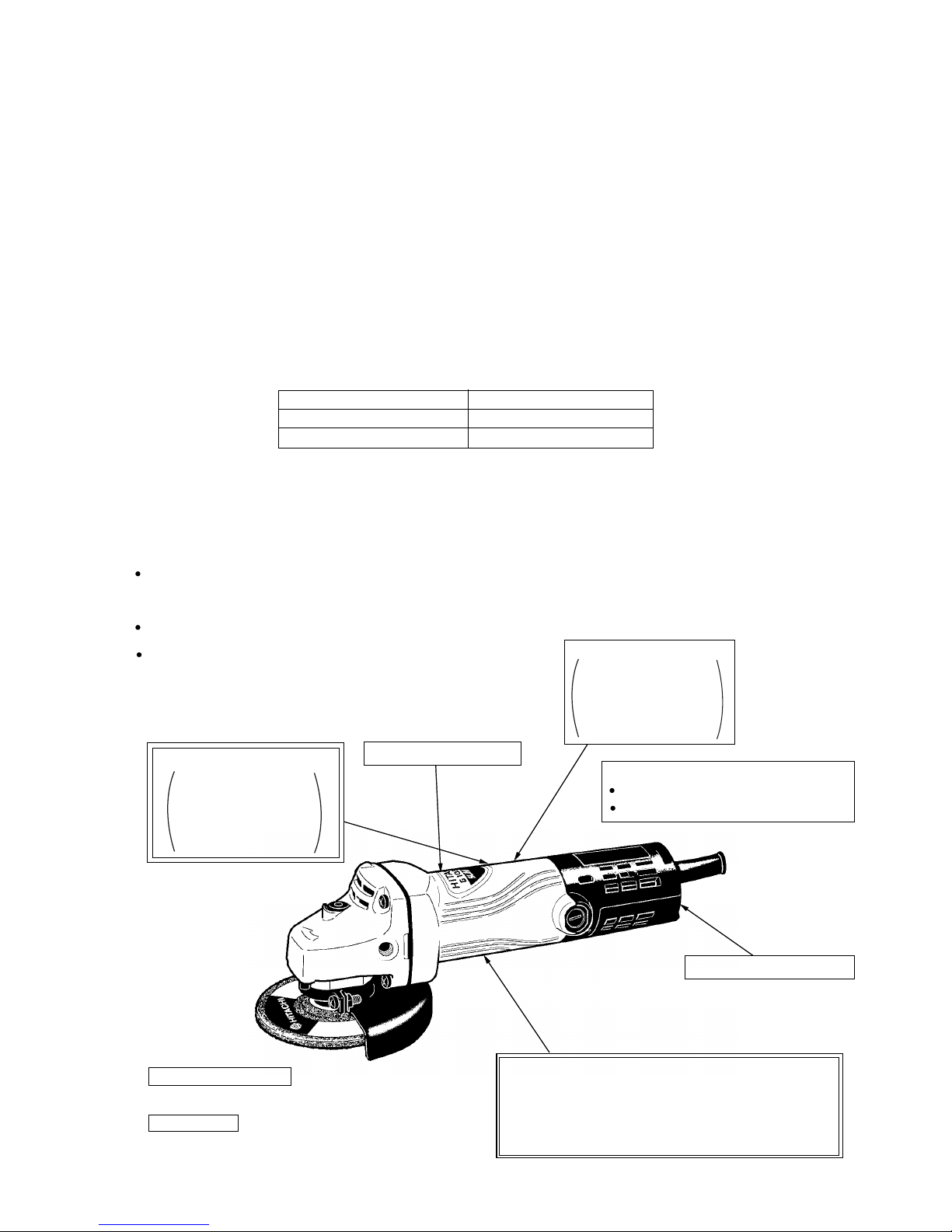
Smaller-diameter grip
Class-first double-insulated aluminum housing
(Model PDA-100G only)
Resistance (heat and strength):
Equivalent to an aluminum housing
Insulation: Equivalent to a mold housing
Durable gear ass'y
(Oil-impregnated sintered gear)
Low noise
(Gears are meshed with play.)
Durable motor
Extended armature wedge
Vent is resistant to sucking gravel.
Maximum output: 900 W
PDA-100D: 710 W
G 10SB1: 560 W
G 10SK: 800 W
B: 750 W
C: 745 W
Page 5
--- 2 ---
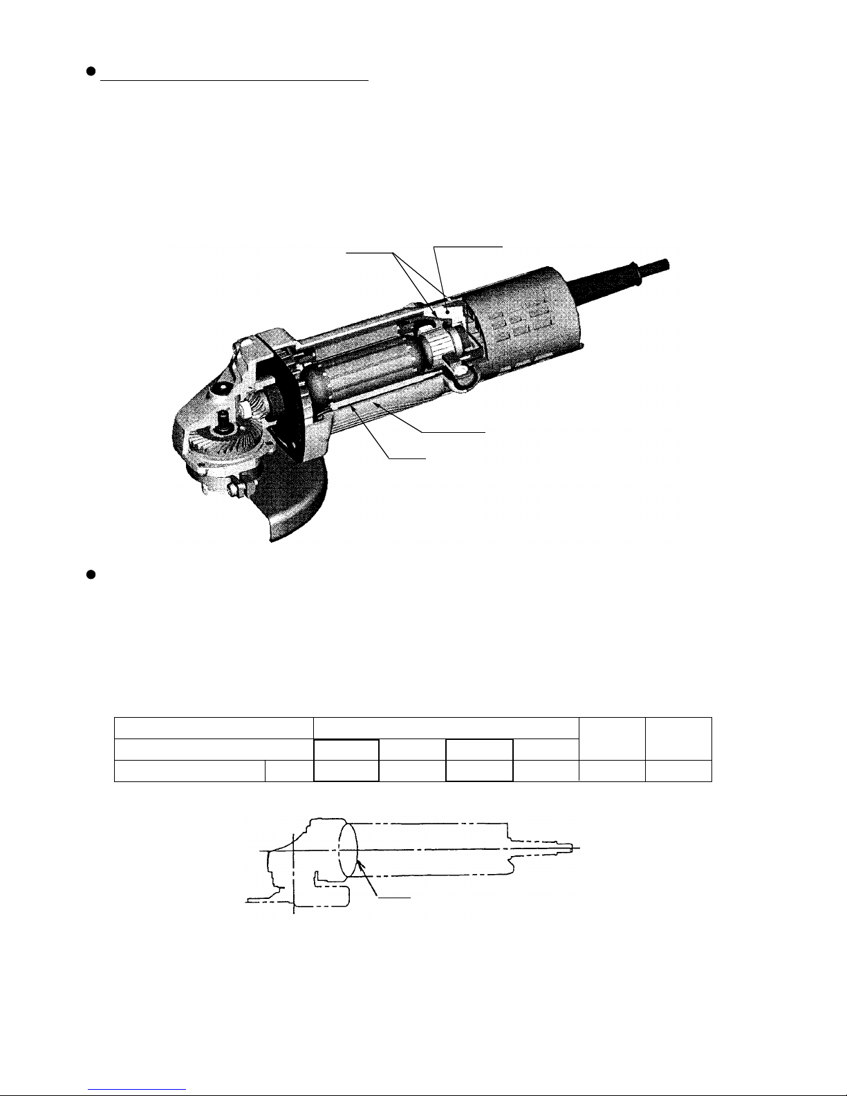
Class-first double-insulated aluminum housing (Model PDA-100G only)
Injection molding is partially conducted on the conventional aluminum die-cast housing to make the aluminum
housing double-insulated. Thus the Model PDA-100G offers high insulation and light weight that are
advantages of a mold housing as well as resistance against heat and external force that is an advantage of an
aluminum housing. The Model PDA-100G causes no melting in the ball bearing chamber that is a weak point
of the mold housing thanks to the new housing construction and the service life of the housing is longer than
the conventional model.
Maker
B
HITACHI
Model
PDA-100G
187
Perimeter of grip* mm 191
G 10SK
176
G 10SK2
176
PDA-100D
200
C
195
P
Small-diameter grip
The Models PDA-100G and G 10SK2 are equipped with a small-diameter grip that is common to the wellreputed conventional models. The Model PDA-100G offers higher operability than the conventional Model
PDA-100D and the Model G 10SK2 offers operability equivalent to the conventional Model G 10SK.
In addition, the Models PDA-100G and G 10SK2 are lightweight and offer less user fatigue even though they
are used for a long time.
* Perimeter of grip is the dimension "P" shown below.
Aluminum
Mold
Aluminum
Mold
Page 6
--- 3 ---
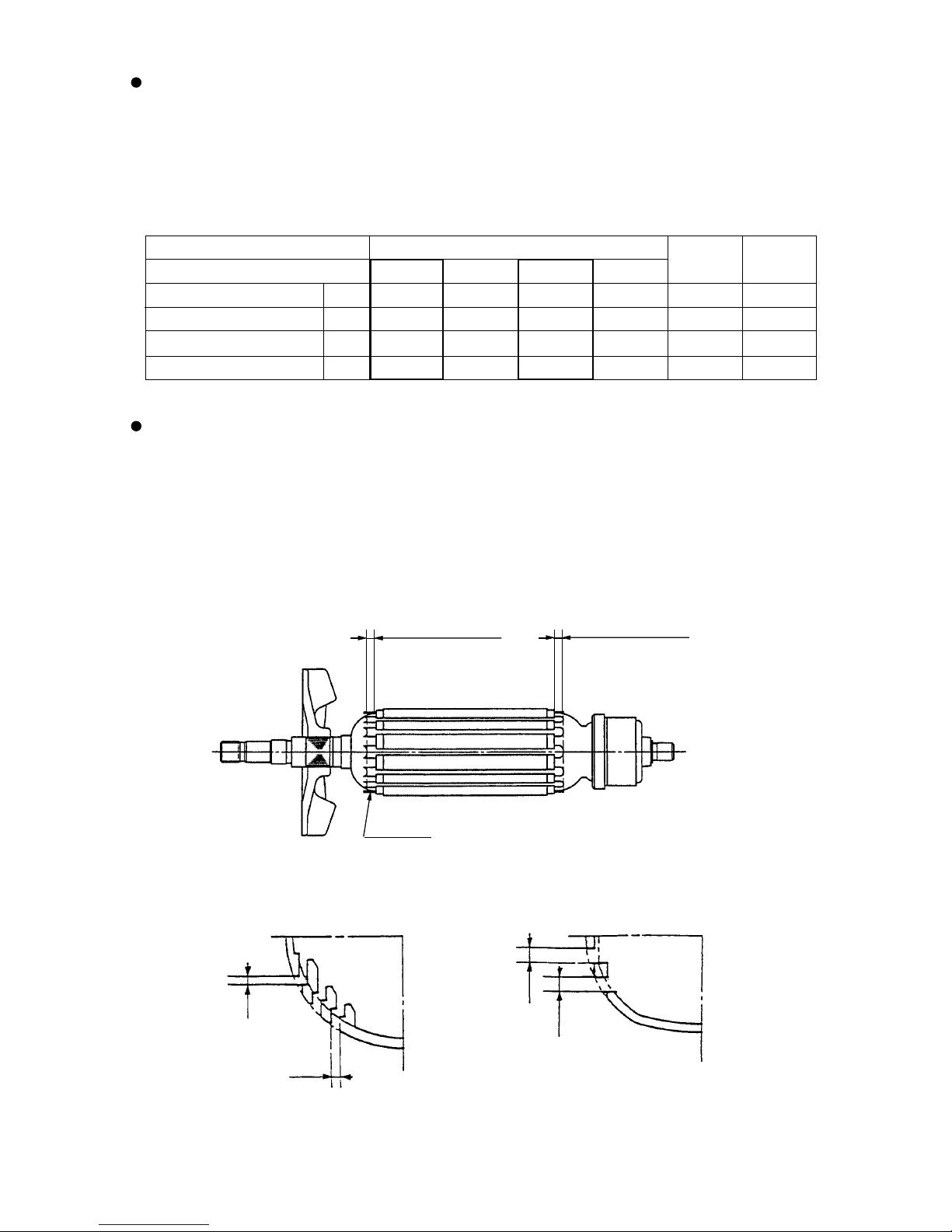
Durable motor
The Models PDA-100G and G 10SK2 are equipped with a motor whose durability is greater than the
conventional models by making the following improvements. The service life of the armature coil is 2 times
longer than the conventional models as a result of the gravel suction test (gravel is forcedly sucked in through
the vents of the tail cover).
(1) The wedges at both ends of the armature coil are extended by 3 to 4.5 mm to protect the portions where
the peripheral speed is the fastest and apt to be disconnected by dust or gravel.
Maker
B
HITACHI
Model
PDA-100G
705
900
1.55
581
670
760
1.40
543
G 10SK
580
820
1.34
612
G 10SK2
705
900
1.39
647
PDA-100D
620
800
1.95
410
C
540
770
1.48
520
3 mm to 4.5mm
3 mm to 4.5mm
Wedge
High power input and maximum power output
The Models PDA-100G and G 10SK2 are compact and lightweight, but powerful and offer higher power input
than the conventional Models PDA-100D and G 10SK thanks to the high-power motor. It is said that the
greater the maximum power output/weight is, the better performance the motor offers. Table 1 shows a
comparison of the motor performance. It is clear that the Models PDA-100G and G 10SK2 have higher
performance than the conventional Models PDA-100D and G 10SK respectively.
* Actual weight excludes cord, depressed center wheel, wheel nut, wheel washer and wheel guard.
Models PDA-100G and G 10SK2
(Dust or gravel is hard to be sucked in.)
Models PDA-100D and G 10SK
2
3
3
2
New vent construction is adopted to prevent dust or gravel from getting inside.
(Comparison of vent construction)
Max. power output W
Weight* (actual)
Max. power output/weight
kg
W/kg
Power input W
Page 7
--- 4 ---
Durable gear ass'y
The service life of the gear ass'y is 2 times longer than the conventional models thanks to the new greasing
method; vacuum-impregnation of lubricate grease into the holes on the sintered gear, in addition to the
conventional greasing.
Low gear noise
The gear festening method is changed from the conventional press-fitting method to the new method. The
gear is fastened to the spindle by a woodruff key keeping a proper clearance to reduce the variations in gear
noise level to the minimum level.
Depressed
center
wheel
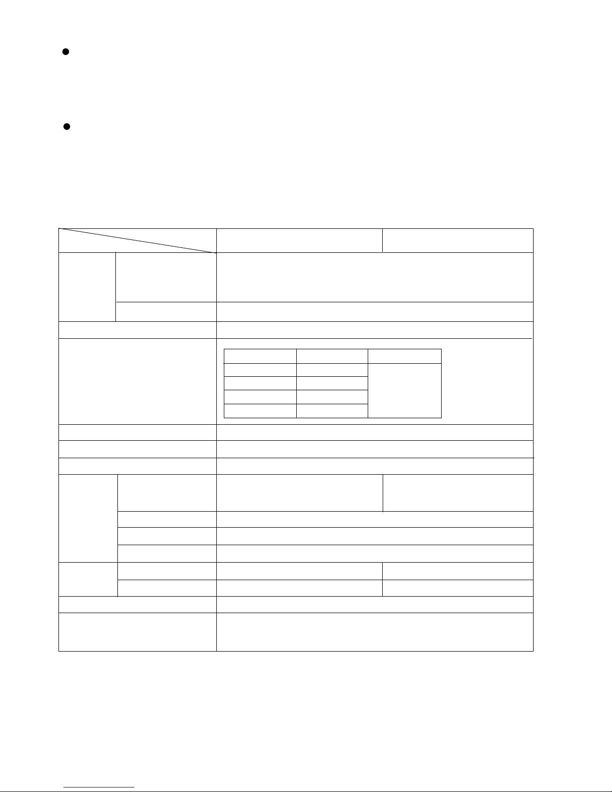
5. SPECIFICATIONS
4,300 m/min (14,100 ft/min, 72 m/s)
Dimensions
Model
Item
O.D. 100 mm (4") x Thickness 6 mm (1/4")
x I.D. 16 mm (5/8")
Offset amount: 4 mm (5/32")
Max. peripheral speed
PDA-100G
AC single phase 50 or 60 Hz
Power source
Glassfiber reinforced polyamide resin (black)
Aluminum alloy die casting (metallic silver)
Aluminum alloy die casting
1.5 kg (3.3 lbs.) 1.4 kg (3.1 lbs.)
2.5 kg (5.5 lbs.) 2.4 kg (5.3 lbs.)
Corrugated cardboard box
Rotation speed (no-load)
Type of motor
Type of switch
Enclosure
Net: *
1
Gross:
Packaging
Standard accessories*
2
Depressed center wheel [Outer dia.100 mm (4") ] ................. 1
Wrench ................................................................................... 1
Voltage, current and power input
12,000/min
AC single-phase commutator motor
Snap switch
Housing
Tail cover
Gear cover
Packing gland
Voltage (V)
110
220
230
240
Current (A)
6.7
3.3
3.2
3.1
Power input (W)
705
*1 : Net weight excludes cord, depressed center wheel, wheel nut, wheel washer and wheel guard.
*2 : Standard accessories are subject to change without prior notice.
G 10SK2
Aluminum alloy die casting (metallic
silver) and glassfiber reinforced
polyamide resin (green)
Glassfiber reinforced polyamide
resin (green)
Weight
Page 8
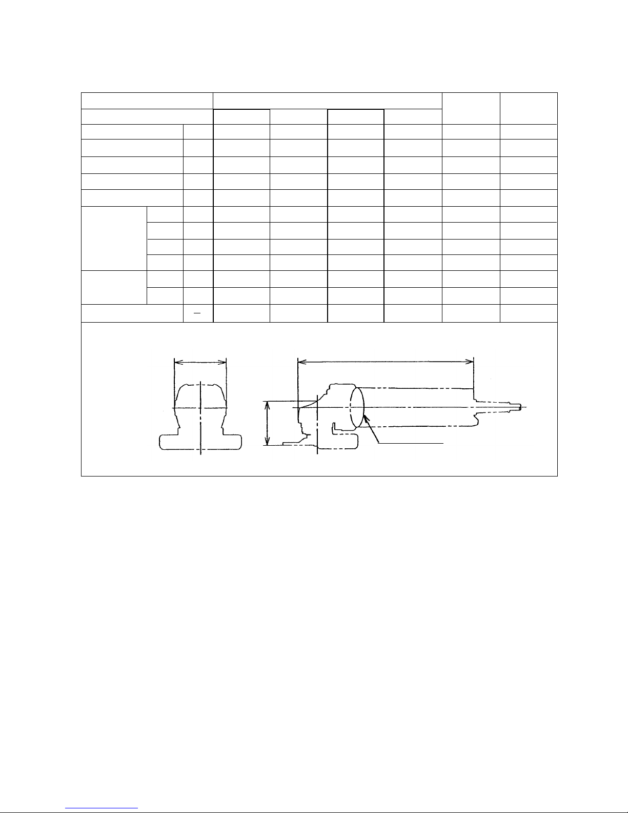
--- 5 ---
Maker
Model
Wheel diameter mm
No-load speed /min
Power input W
Power output W
Max. power output W
Lmm
Dimensions W mm
Hmm
Pmm
Weight * Catalog kg
Actual kg
Type of switch
HITACHI
PDA-100G
100
12,000
705
440
900
258
72
63
187
1.5
1.6
Snap
6. COMPARISONS WITH SIMILAR PRODUCTS
6-1. Specification Comparisons
G 10SK
100
12,000
580
330
820
254
67
60
176
1.4
1.4
Snap
100
11,000
540
250
770
256
81
70
195
1.4
1.5
Slide
C
L
H
W
P: Perimeter
* Weight excludes cord, depressed center wheel, wheel nut, wheel washer and wheel guard.
100
11,000
670
360
760
265
76
73
191
1.4
1.4
Slide
G 10SK2
100
12,000
705
440
900
258
72
63
176
1.4
1.4
Snap
PDA-100D
100
12,000
620
410
800
254
67
60
200
1.7
2.0
Snap
B
Page 9

--- 6 ---
6-2. Comparisons in Torque vs. Rotation Speed and Stator Coil Temperature Rise
Figure 1 shows comparisons of the rotation speed and the stator coil temperature rise between a competitive
model with respect to torque. Torque represents the magnitude of load, i.e., the amount of pressing force, cutting
depth and forward force in actual cutting jobs. This shows that a powerful motor is less likely to burn out because
it has both a minimum drop of rotation speed even at a greater torque and a lower stator coil temperature rise at
the same torque.
Fig. 1 Comparisons in torque vs. rotation speed and stator coil temperature rise
Figure 1 indicates the following:
The motor speed of the Models PDA-100G and G 10SK2 is higher than that of B, C, Models PDA-100D and
G 10SK at the same torque. This means that the working efficiency of the Models PDA-100G and G 10SK2
are superior to B, C, Models PDA-100D and G 10SK.
The stator coil temperature rise of the Models PDA-100G and G 10SK2 is lower than that of B, C and Model
G 10SK2 thanks to the improved cooling mechanism and it is equivalent to that of the Model PDA-100D.
This means that the Models PDA-100G and G 10SK2 have a burn-resistant and tenacious motor.
Load
Stator coil temp. rise (K)
2,000
0
B
4,000
6,000
8,000
12,000
10,000
0
0
600
100
200
300
400
500
Rotation speed of spindle (/min.)
Torque range
Stator coil temp. rise X: Burn-out point
HITACHI G 10SK
HITACHI G 10SK2
HITACHI PDA-100G
HITACHI PDA-100G, G 10SK2
B
HITACHI PDA-100G, G 10SK2
HITACHI PDA-100D
Rotation speed of spindle
X
X
X
X
X
C
C
Page 10

--- 7 ---
7. PRECAUTIONS IN SALES PROMOTION
In the interest of promoting the safest and most efficient use of the Models PDA-100G and G 10SK2 Disc
Grinders by all of our customers, it is very important that at the time of sale, the salesperson carefully ensures that
the buyer seriously recognizes the importance of the contents of the Handling Instructions, and fully understands
the meaning of the precautions listed on the Name Plate attached to each tool.
7-1. Handling Instructions
Although every effort is made in each step of design, manufacture and inspection to provide protection against
any hazards, the dangers inherent in the use of any electric tool cannot be completely eliminated. Accordingly,
general precautions and suggestions for the use of electric power tools, and specific precautions and suggestions
for the use of the disc grinders are listed in the Handling Instructions to enhance the safe, efficient use of the tool
by the customer. Salespersons must be thoroughly familiar with the contents of the Handling Instructions to be
able to offer appropriate guidance to the customer during sales promotion.
7-2. Caution Plate
The following caution is listed on the Name Plate attached to the main body of each tool.
7-3. Precautions on Usage
Instruct the customer to pay particular attention to the two points described below.
(1) Use of the side handle (Optional accessory)
When the side handle is used, the customer must be instructed to ensure without fail that the wheel guard is
mounted in the manner so that it protects the operator's hand from coming into contact with the depressed
center wheel.
Fig. 2
Side handle
Pushing button
Wheel guard
(1) For Taiwan
(2) For China
Side handle
Page 11

--- 8 ---
8. PRECAUTIONS IN DISASSEMBLY AND REASSEMBLY
The [Bold] numbers in the descriptions below correspond to the item numbers in the Parts List and the exploded
assembly diagram for Model PDA-100G, and the <Bold> numbers to those in the Parts List and the exploded
assembly diagram for Model G 10SK2.
8-1. Disassembly
(1) Disassembly of the armature
1) Remove the Brush Caps [42] <41>, and take out the Carbon Brushes [43] <42>.
2) Loosen the four Machine Screws M5 x 22 [1] or the four Tapping Screws D5 x 25 <1> which fix the Gear
Cover Ass'y [4] <3> to remove the Armature [9] <8> from the Housing Ass'y [37] <36> together with the
Bearing Holder [8] <7>.
3) Loosen the Special Nut M7 [5] <4> which fixes the Pinion [6] <5> to remove the Pinion [6] <5>.
4) Insert the hooks of the J-204 bearing puller between the Ball Bearing 628VVC2PS2-L [7] <6> and the
Bearing Holder [8] <7> from both sides and fix the hooks with the wing bolts.
5) Place the J-204 bearing puller on a supporting jig and push down on the tip of the armature shaft with a
hand press to remove the Ball Bearing 628VVC2PS2-L [7] <6>. Then remove the Bearing Holder [8] <7>.
(2) Disassembly of the dust seal
1) Insert the hooks of the J-204 bearing puller between the commutator and the Dust Seal [13] <12> from both
sides, and fix the hooks with the wing bolts.
2) Place the J-204 bearing puller on a supporting jig and push down on the armature shaft with a hand press
to remove the Dust Seal [13] <12> together with the Ball Bearing 626VVC2PS2L [14] <13>. Replace the
Dust Seal [13] <12> with new one because it is damaged by the removal of the Ball Bearing 626VVC2PS2L
[14] <13>.
(3) Disassembly of the Stator (A)
1) Remove the Armature [9] <8> and loosen the Tapping Screw (W/Flange) D4 x 25 (Black) [51] <50> to
remove Tail Cover (B) [50] <49>.
2) Loosen the two Machine Screws (W/Washer) M3.5 x 6 [52] <51> that secure the internal wire of the Cord
[58] <57> and Stator (A) [12] <11> to the Switch (1P Screw Type) [53] <52> and loosen the two screws of
the Pillar Terminal [47] <46>. Remove the two internal wires from the Cord [58] <57> and the Piller
Terminal [47] <46>.
3) Remove the Tapping Screw (W/Flange) D4 x 40 [41] <40> and the Tapping Screw (W/Flange) D4 x 20
(Black) [40] <39>. Remove Tail Cover (A) [39] <38> then remove the Earth Terminal [45] <44> from the
Housing Ass'y [37] <36>.
4) Disconnect the two internal wires of Stator (A) [12] <11> coming from the Brush Holder [44] <43>
from Stator (A) [12] <11>.
(2) Never press the pushing button while the depressed center wheel is rotating.
If the pushing button (Fig. 2) is pressed while the depressed center wheel is rotating, the spindle will stop
immediately. In such a case, there is a danger that the wheel nut may be loosened, so that the depressed
center wheel flies out unexpectedly and may cause possibly serious injury.
Page 12

--- 9 ---
5) Remove the Fan Guide [10] <9> from the Housing Ass'y [37] <36>.
6) Loosen the Tapping Screw D4 x 70 [11] or the Hex. Hd. Tapping Screw D4x70 <10> securing Stator (A)
[12] <11>. Remove Stator (A) [12] <11> from the Housing Ass'y [37] <36>.
(4) Disassembly of the gear
1) Loosen the four Seal Lock Screws (W/SP. Washer) M4 x 12 [25] <24> that secure the Packing Gland [24]
<23> to the Gear Cover Ass'y [4] <3> and remove the Packing Gland [24] <23> from the Gear Cover Ass'y
[4] <3>.
2) Remove the Retaining Ring for D11 Shaft [16] <15> that secures the Gear [19] <18> to the Spindle [27]
<26>.
3) Remove the Wave Washer [17] <16> and the Gear [19] <18> from the Spindle [27] <26>.
Fig. 3
8-2. Reassembly
Push the parts together in the reverse order of disassembly, with the precautions given below.
(1) Ensure that the terminals of the stator are not bent or otherwise damaged.
(2) Generously lubricate the teeth of Gear [19] <18> and Pinion [6] <5> with grease. Rub grease onto the teeth
with your fingers so that the grease reaches each tooth bottom. Note that the Gear [19] <18> and the Pinion
[6] <5> may wear faster than normal if under-lubricated.
(3) Be sure to soak the inner diameter of the Felt Packing [23] <22> with machine oil. Otherwise, its dust-sealing
function will fail to work properly, resulting in earlier damage of the Ball Bearing 6201VVCMPS2L [22] <21>.
(4) When replacing the Armature [9] <8> and the Ball Bearing 626VVC2PS2L [14] <13> on the commutator side,
press inward on the Dust Seal [13] <12> while taking care of its direction until the end face of the Dust Seal
[13] <12> contacts against the end surface of the Armature [9] <8> and make sure that Dust Seal [13] <12>
cannot be turned freely by hand. Keep the end face of the armature shaft approximately 0.2 mm (reference)
distance inward of the end face of the Ball Bearing 626VVC2PS2L [14] <13>. (See Fig. 3.)
The Dust Seal [13] <12> is an important element for improved dust protection of the Ball Bearing
626VVC2PS2L [14] <13>. Be sure to replace with a new one each time.
Armature shaft
About 0.2 mm (reference)
Ball Bearing 626VVC2PS2L [14] <13>
Dust Seal [13] <12>
(5) When connecting the Earth Terminal [45] <44> to the internal wire (the middle wire among three) of the Noise
Suppressor [49] <48>, strip the insulation sheath on the internal wire by about 6 mm and press-connect it
together with the Earth Terminal [45] <44> with a clamping tool available on the market.
Fig. 4
Solderless connection
Page 13

--- 10 ---
(6) Mount the Cord [58] <57> according to the following
procedure when replacing the standard cord (cord armor is
integrally molded).
1) Remove the standard cord (cord armor is integrally
molded) according to the procedure of 8-1 (3).
2) Strip the coating on the internal wire of the Cord
[58] <57> about 10 mm from the tip and crimp the
Terminal [54] <53> to the brown or black internal wire as
shown in Fig. 5.
3) Insert the Cord [58] <57> into the Cord Armor D8.8 [55]
<54>.
4) Cut off the rib for holding the cord of Tail Cover (B) [50]
<49> with nippers as shown in Fig. 6.
5) Mount the Cord [58] <57> and the Cord Armor D8.8
[55] <54> to Tail Cover (A) [39] <38> and secure them
with the Cord Clip [56] <55> and two Tapping Screw
(W/Flange) D4 x 16 [57] <56> as shown in Fig. 7.
6) Mount each internal wire reversing the removal
procedure. Then mount Tail Cover (B) [50] <49> to Tail
Cover (A) [39] <38> and secure them with the Tapping
Screw (W/Flange) D4 x 25 (Black) [51] <50>.
Fig. 6
Fig. 7-1
Fig. 7-2
Fig. 5
Terminal [54] <53>
Cord [58] <57>
Caulking
A
Stripped
length
10 mm
White
or blue
40 mm
85 mm
Black or brown
A --- A
Tail Cover (B)
[50] <49>
A
Approximately
2 mm
(a) For Taiwan and Korea
(b) For China
(c) For Singapore and Malaysia
(d) For other countries
: Cut off.
Page 14

--- 11 ---
Fig. 8
Fig. 9
Bottom of the housing
(7) Connect the internal wires of Stator (A) [12] <11> correctly as shown in Fig. 8 and Fig. 9.
(8) Connect each internal wire correctly as shown in Fig. 7 being careful not to put them between the parts.
Brush Holder [44] <43>
Internal wire from Cord [58] <57>
Machine Screw (W/Washer) M3.5 x 6 [52] <51>
Guide Plate (Attached switch for Taiwan,
Singapore, Malaysia, China, Korea)
Machine Screw (W/Washer) M3.5 x 6 [52] <51>
Switch (1P Screw Type) [53] <52>
: Tail Cover (A) [39] <38>
Internal wire from Stator (A) [12] <11>
Internal wire from Noise Suppressor [49] <48>
Fig. 9
Internal wire coming from the
Noise Suppressor [49] <48>
Colorless
Insert the terminal securely then push
and fold the terminal toward the outside
of the housing as much as possible.
Colorless
(9) When replacing the Gear Cover Ass'y [4] <3>, lubricate the metal part with mixed oil.
Mixed oil: A mixture of Hitachi Power Tool Grease No. 2 (Unilube No. 00 Code No. 939302 is recommended)
and turbine oil
Mixture ratio ......... 1:1 (weight ratio) Quantity ........... 0.5 cc
OFF side
ON side
Page 15

--- 12 ---
8-3. Lubrication Points and Types of Lubricant
Pinion chamber of Gear Cover Ass'y [4] <3> .............. Nippeco grease (SEP-3A) 5 g
(Code No. 930035 is recommended.)
Generously rub grease onto the gear and pinion.
Metal ............................................................................ Mixed oil 0.5 cc
Mixed oil: Mixture of Hitachi Power Tool Grease No. 2
(Unilube No. 00, Code No. 939302) and
turbine oil
Mixture ratio ................ 1:1 (weight ratio)
8-4. Tightening Torque
D4 Tapping Screws
[11] <10> [40] <39> [41] <40> [51] <50> [57] <56> .............. 2.0 0.5 N•m (20 5 kgf•cm, 1.5 0.4 fb-lbs.)
M4 Seal Lock Screws (W/Sp. Washer) [20] <19> [25] <24>.. 1.8 0.4 N•m (18 4 kgf•cm, 1.3 0.3 fb-lbs.)
M5 Machine Screw [1] ............................................................ 3.7 0.7 N•m (35 7 kgf•cm, 2.6 0.6 fb-lbs.)
D5 Tapping Screw <1> ............................................................ 2.9 0.5 N•m (30 5 kgf•cm, 2.2 0.4 fb-lbs.)
M5 Machine Screw (W/Sp. Washer)
[29] <28> .........................
1.6 0.4 N•m (16 4 kgf•cm, 1.2 0.3 fb-lbs.)
M7 Special Nut [5] <4> ........................................................... 6.4 1.0 N•m (65 10 kgf•cm, 4.7 0.7 fb-lbs.)
Brush Cap [42] <41> .............................................................. 0.6 0.2 N•m (6 2 kgf•cm, 0.4 0.1 fb-lbs.)
8-5. Wiring Diagram
(1) For Taiwan (2) For Korea
Gray
Noise
Suppressor
Cord
Switch
Stator
Black
Black
Red
Colorless
Stator
Gray
White
Red
Black
Connector
1
3
Gray
Noise
Suppressor
Cord
Switch
Stator
Brown
Black
Colorless
Stator
Gray
Blue
Black
Connector
1
3
CR unit
Black
Black
Gray
Noise
Suppressor
Cord
Switch
Stator
Brown
Black
Black
Colorless
Stator
Gray
Blue
Black
Piller Terminal
1
3
Gray
Cord
Switch
Stator
Brown
Black
Stator
Gray
Blue
Black
1
3
(3) For China (4) For Singapore and Malaysia
CR unit
Black
Piller Terminal
Page 16

--- 13 ---
8-6. Insulation Tests
On completion of disassembly and repair, carefully measure the insulation resistance and conduct a dielectric
strength test.
Insulation resistance: 7 M Ω or more with 500 V DC Megohm Tester
Dielectric strength test: AC 4,000 V/1 minute with no abnormalities .................... 220 V --- 240 V products
AC 2,500 V/1 minute with no abnormalities .................... 110 V --- 127 V products
8-7. No-load Current Value
After no-load running for 30 minutes, the no-load current value should be as follows.
Voltage (V)
Current (A) max.
110
3.0
(5) For other countries
220
1.6
240
1.7
230
1.8
Gray
Cord
Switch
Stator
Brown
Black
Stator
Gray
Blue
Black
Connector
1
3
Page 17

--- 14 ---
9. STANDARD REPAIR TIME (UNIT) SCHEDULES
MODEL 10 20 30 40
Fixed
Variable
Work Flow
Pushing Button
Gear Cover
Ass'y
Lock Pin
Gear
60 min.50
Bearing Cover
Ball Bearing
(6201VVCM)
Felt Packing
Packing Gland
Spindle
Flinger
Wheel Guard
Ass'y
Switch
Cord
Tail Cover (A)
Tail Cover (B)
Pinion
Ball Bearing
(626VVC2)
Ball Bearing
(628VVC2)
Bearing Holder
Armature
Dust Seal
General Assembly
PDA-100G
Housing Ass'y
Stator
G 10SK2
Page 18

ELECTRIC TOOL PARTS LIST
LIST NO.
DISC GRINDER
Model PDA-100G
2002 • 3 •25
(E1)
E248
1
2
3
4
5
6
7
8
9
10
11
12
13
14
15
16
17
18
19
20
21
22
23
24
25
26
27
28
29
30
31
32
33
34
35
36
37
38
39
40
41
42
43
44
45
46
47
48
49
50
51
52
53
54
55
56
57
58
501
Page 19

*
ALTERNATIVE PARTS
--- 2 ---
ITEM
NO.
CODE NO.
DESCRIPTION
REMARKS
NO.
USED
PARTS
3 -- 02
PDA-100G
1 949-242 MACHINE SCREW M5X22 (10 PCS.) 4
2 949-454 SPRING WASHER M5 (10 PCS.) 4
3 301-944 PUSHING BUTTON 1
4 319-095 GEAR COVER ASS’Y 1 INCLUD. 3, 18
5 301-941 SPECIAL NUT M7 1
6 317-820 PINION 1
7 628-VVC BALL BEARING 628VVC2PS2-L 1
8 316-480 BEARING HOLDER 1
* 9 360-567C ARMATURE 110V 1
* 9 360-567E ARMATURE 220V-240V 1
10 319-898 FAN GUIDE 1
11 320-677 TAPPING SCREW D4X70 2
* 12 340-514C STATOR (A) 110V 1
* 12 340-514E STATOR (A) 220V-230V 1
* 12 340-514G STATOR (A) 220V-230V 1 FOR CHN, KOR
* 12 340-514F STATOR (A) 240V 1
13 313-775 DUST SEAL 1
14 626-VVM BALL BEARING 626VVC2PS2L 1
15 309-929 RUBBER BUSHING 1
16 316-487 RETAINING RING FOR D11 SHAFT 1
17 316-486 WAVE WASHER 1
18 301-943 LOCK PIN 1
19 317-821 GEAR 1
20 997-263
SEAL LOCK SCREW (W/SP. WASHER) M4X10 2
21 316-490 BEARING COVER 1
22 620-1VV BALL BEARING 6201VVCMPS2L 1
23 301-946 FELT PACKING 1
24 316-489 PACKING GLAND 1
25 307-127
SEAL LOCK SCREW (W/SP. WASHER) M4X12 4
26 302-047 WOODRUFF KEY 1
27 316-485 SPINDLE 1
28 301-945 FRINGER 1
29 308-386
MACHINE SCREW (W/SP. WASHER) M5X16 (BLACK) 2
30 301-949 SET PLATE 1
31 301-948 WHEEL GUARD ASS’Y 1 INCLUD. 29, 30
32 320-497 WHEEL WASHER 1
33 316-820 D. C. WHEELS 100MMX4T A36Q (25 PCS.) 1
34 314-437 WHEEL NUT (C) 1
35 317-819 GEAR ASS’Y 1 INCLUD. 6, 19
36 HITACHI LABEL 1
37 320-675 HOUSING ASS’Y 1 INCLUD. 15
38 NAME PLATE 1
39 320-668 TAIL COVER (A) 1
40 302-086
TAPPING SCREW (W/FLANGE) D4X20 (BLACK) 1
41 306-664 TAPPING SCREW (W/FLANGE) D4X40 1
42 936-551 BRUSH CAP 2
43 999-021 CARBON BRUSH (1 PAIR) 2
44 313-777 BRUSH HOLDER 2
* 45 314-854 EARTH TERMINAL 1 FOR TPE, CHN, KOR
* 46 980-063 TERMINAL 1 FOR TPE, CHN, KOR
* 47 938-307 PILLAR TERMINAL 1 FOR SIN, MAL, CHN
Page 20

*
ALTERNATIVE PARTS --- 3 ---
ITEM
NO.
CODE NO.
DESCRIPTION
REMARKS
NO.
USED
PARTS
3 -- 02
PDA-100G
* 48 959-140 CONNECTOR 50091 (10 PCS.) 1 EXCEPT FOR SIN, MAL
* 49 994-273 NOISE SUPPRESSOR 1 FOR TPE, CHN, KOR
50 320-667 TAIL COVER (B) 1
51 304-035
TAPPING SCREW (W/FLANGE) D4X25 (BLACK) 1
52 305-499 MACHINE SCREW (W/WASHER) M3.5X6 2
53 955-509 SWITCH (1P SCREW TYPE) 1
54 980-063 TERMINAL 1
55 953-327 CORD ARMOR D8.8 1
56 937-631 CORD CLIP 1
57 984-750 TAPPING SCREW (W/FLANGE) D4X16 2
* 58 500-231Z CORD 1
* 58 500-212Z CORD 1 FOR TPE, THA, PHI
* 58 500-409Z CORD 1 FOR INA, VIE, KOR
* 58 500-455Z CORD 1 FOR CHN
Page 21

*
ALTERNATIVE PARTS
--- 4 ---
STANDARD ACCESSORIES
OPTIONAL ACCESSORIES
ITEM
NO.
CODE NO.
DESCRIPTION
REMARKS
NO.
USED
ITEM
NO.
CODE NO.
DESCRIPTION
REMARKS
NO.
USED
3 -- 02
PDA-100G
501 313-933 WRENCH 1
601 302-098 GUIDE BASE 1
602 302-099
WHEEL GUARD FOR 100MM CUT-OFF WHEEL 1
603 984-646
WHEEL NUT FOR 100MM CUT-OFF WHEEL
1
604 986-381 DUST COLLECTOR (FOR DISC GRINDER) 1
605 314-053 SANDING DISCS 100MM C-P24 (10 PCS.) 1
606 314-054 SANDING DISCS 100MM C-P30 (10 PCS.) 1
607 314-057 SANDING DISCS 100MM C-P50 (10 PCS.) 1
608 314-059 SANDING DISCS 100MM C-P80 (10 PCS.) 1
609 314-061 SANDING DISCS 100MM C-P120 (10 PCS.) 1
610 314-051 SANDING DISCS 100MM C-P16 (10 PCS.) 1
611 314-052 SANDING DISCS 100MM C-P20 (10 PCS.) 1
612 314-055 SANDING DISCS 100MM C-P36 (10 PCS.) 1
613 314-056 SANDING DISCS 100MM C-P40 (10 PCS.) 1
614 314-058 SANDING DISCS 100MM C-P60 (10 PCS.) 1
615 314-060 SANDING DISCS 100MM C-P100 (10 PCS.) 1
616 935-513 WASHER NUT M10XP1.5 1
617 936-548 WASHER 1
618 936-558Z RUBBER PAD 1
619 302-142 SIDE HANDLE 1
620 954-021 SIDE HANDLE 1
Printed in Japan
(020325N)
Page 22

ELECTRIC TOOL PARTS LIST
LIST NO.
DISC GRINDER
Model G 10SK2
2002• 3•25
(E1)
E249
1
2
3
4
5
6
7
8
9
10
11
12
13
14
15
16
17
18
19
20
21
22
23
24
25
26
27
28
29
30
31
32
33
34
35
36
37
38
39
40
41
42
43
44
45
46
47
48
49
50
51
52
53
54
55
56
57
501
Page 23

*
ALTERNATIVE PARTS
--- 2 ---
ITEM
NO.
CODE NO.
DESCRIPTION
REMARKS
NO.
USED
PARTS
3 -- 02
G 10SK2
1 937-807 TAPPING SCREW D5X25 4
2 301-944 PUSHING BUTTON 1
3 319-095 GEAR COVER ASS'Y 1 INCLUD.2,17
4 301-941 SPECIAL NUT M7 1
5 317-820 PINION 1
6 628-VVC BALL BEARING 628VVC2PS2-L 1
7 316-480 BEARING HOLDER 1
* 8 360-567C ARMATURE 110V 1
* 8 360-567E ARMATURE 220V-240V 1
9 319-898 FAN GUIDE 1
10 982-021 HEX. HD. TAPPING SCREW D4X70 2
* 11 340-514C STATOR (A) 110V 1
* 11 340-514E STATOR (A) 220V-230V 1
12 313-775 DUST SEAL 1
13 626-VVM BALL BEARING 626VVC2PS2L 1
14 319-093 RUBBER BUSHING 1
15 316-487 RETAINING RING FOR D11 SHAFT 1
16 316-486 WAVE WASHER 1
17 301-943 LOCK PIN 1
18 317-821 GEAR 1
19 997-263
SEAL LOCK SCREW (W/SP. WASHER) M4X10 2
20 316-490 BEARING COVER 1
21 620-1VV BALL BEARING 6201VVCMPS2L 1
22 301-946 FELT PACKING 1
23 316-489 PACKING GLAND 1
24 307-127
SEAL LOCK SCREW (W/SP. WASHER) M4X12 4
25 302-047 WOODRUFF KEY 1
26 316-485 SPINDLE 1
27 301-945 FRINGER 1
28 308-386
MACHINE SCREW (W/SP. WASHER) M5X16 (BLACK)
2
29 301-949 SET PLATE 1
30 301-948 WHEEL GUARD ASS'Y 1 INCLUD.28,29
31 320-497 WHEEL WASHER 1
32 316-820 D. C. WHEELS 100MMX4T A36Q (25 PCS.) 1
33 314-437 WHEEL NUT (C) 1
34 317-819 GEAR ASS'Y 1 INCLUD.5,18
35 HITACHI LABEL 1
36 320-666 HOUSING ASS'Y 1 INCLUD.14
37 NAME PLATE 1
38 320-668 TAIL COVER (A) 1
39 302-086
TAPPING SCREW (W/FLANGE) D4X20 (BLACK) 1
40 306-664 TAPPING SCREW (W/FLANGE) D4X40 1
41 936-551 BRUSH CAP 2
42 999-021 CARBON BRUSH (1 PAIR) 2
43 313-777 BRUSH HOLDER 2
* 44 314-854 EARTH TERMINAL 1 FOR TPE
* 45 980-063 TERMINAL 1 FOR TPE
* 46 938-307 PILLAR TERMINAL 1 FOR SIN,MAL
* 47 959-140 CONNECTOR 50091 (10 PCS.) 1 EXCEPT FOR SIN,MAL
* 48 994-273 NOISE SUPPRESSOR 1 FOR TPE
49 320-667 TAIL COVER (B) 1
Page 24

*
ALTERNATIVE PARTS --- 3 ---
ITEM
NO.
CODE NO.
DESCRIPTION
REMARKS
NO.
USED
PARTS
3 -- 02
G 10SK2
50 304-035 TAPPING SCREW (W/FLANGE) D4X25 (BLACK) 1
51 305-499 MACHINE SCREW (W/WASHER) M3.5X6 2
52 955-509 SWITCH (1P SCREW TYPE) 1
53 980-063 TERMINAL 1
54 953-327 CORD ARMOR D8.8 1
55 937-631 CORD CLIP 1
56 984-750 TAPPING SCREW (W/FLANGE) D4X16 2
* 57 500-212Z CORD 1
* 57 500-409Z CORD 1 FOR INA
* 57 500-231Z CORD 1 FOR SIN,HKG,MAL
Page 25

*
ALTERNATIVE PARTS
--- 4 ---
STANDARD ACCESSORIES
OPTIONAL ACCESSORIES
ITEM
NO.
CODE NO.
DESCRIPTION
REMARKS
NO.
USED
ITEM
NO.
CODE NO.
DESCRIPTION
REMARKS
NO.
USED
3 -- 02
G 10SK2
501 313-933 WRENCH 1
601 302-098 GUIDE BASE 1
602 302-099
WHEEL GUARD FOR 100MM CUT-OFF WHEEL 1
603 984-646 WHEEL NUT FOR 100MM CUT-OFF WHEEL 1
604 986-381 DUST COLLECTOR (FOR DISC GRINDER) 1
605 314-051 SANDING DISCS 100MM C-P16 (10 PCS.) 1
606 314-052 SANDING DISCS 100MM C-P20 (10 PCS.) 1
607 314-053 SANDING DISCS 100MM C-P24 (10 PCS.) 1
608 314-054 SANDING DISCS 100MM C-P30 (10 PCS.) 1
609 314-055 SANDING DISCS 100MM C-P36 (10 PCS.) 1
610 314-056 SANDING DISCS 100MM C-P40 (10 PCS.) 1
611 314-057 SANDING DISCS 100MM C-P50 (10 PCS.) 1
612 314-058 SANDING DISCS 100MM C-P60 (10 PCS.) 1
613 314-059 SANDING DISCS 100MM C-P80 (10 PCS.) 1
614 314-060 SANDING DISCS 100MM C-P100 (10 PCS.) 1
615 314-061 SANDING DISCS 100MM C-P120 (10 PCS.) 1
616 935-513 WASHER NUT M10XP1.5 1
617 936-548 WASHER 1
618 936-558Z RUBBER PAD 1
619 302-142 SIDE HANDLE 1
620 954-021 SIDE HANDLE 1
Printed in Japan
(020325N)
Page 26

 Loading...