

Page 1

ROUTER
OBERFRÄSE
DÉFONCEUSE
FRESATRICE VERTICALE
BOVENFREESMACHINE
RANURADORA
FM 8
1
ON
0
O
FF
Read through carefully and understand these instructions before use.
Diese Anleitung vor Benutzung des Werkzeugs sorgfältig durchlesen und verstehen.
Lire soigneusement et bien assimiler ces instructions avant usage.
Prima dell’uso leggere attentamente e comprendere queste istruzioni.
Deze gebruiksaanwijzing s.v.p. voor gebruik zorgvuldig doorlezen.
Leer cuidadosamente y comprender estas instrucciones antes del uso.
Handling instructions
Bedienungsanleitung
Mode d’emploi
Istruzioni per l’uso
Gebruiksaanwijzing
Instrucciones de manejo
Page 2

15
×
Part Name
42 Wing Bolt M6
No.
Item
Part Name
1 HITACHI Label
No.
Item
Wrench 10/13mm
43 Lock Spring
44 Earth Terminal
501 Parallel Guide
502A
2 Housing
3 Carbon Brush
4 Brush Holder
5 Noise Suppressor
6
×
503 Wrench 13/17mm
504 Chuck Sleeve
505 Template Guide D18
506 Machine Screw M5
20
×
Tapping Screw(W/Flange) D4 × !6
Tapping Screw(W/Washer) D4
6 Pillar Terminal
7 Connector (50091)
8 Cord
9 Cord Clip
10
11
Parts are subject to possible modifica-
tion without notice due to improve-
ments.
12 Name Plate
13 Cord Armor
14 Terminal (A)
15 Switch Knob
17 Switch Holder
18 Ball Bearing (608VVMC2EPS2L)
19 Rubber Ring
20 Internal Wire
21 Internal Wire (A)
22 Stator
23 Armature
24 Retaining Ring For D15 Shaft
16A Switch
25 Ball Bearing (6002VVCMPS2S)
26 Spindle
27 Collet
28 Internal Wire (A)
29 Internal Wire (A)
30 Scale
31 Knob
32 Holder
33 Knob Screw M5
34 Nut M6
35 Spring
36 Nut M8
37 Base
100
×
38A Screw M8
39 Look Nut M8
40 Knob Bolt
41 Steel Ball D7.94
The exploded assembly drawing should be used only for authorized service center.
Page 3

1
9
A
3
2
2
6
4
7
7
H
8
2
2
A
9
1
0
3
5
4
E
6
D
G
F
J
I
K
5
7
7
6
5
4
3
2
1
B
(a)
6
5
4
3
2
1
(b)
C
8
10
1
1
2
4
5
11
12
1
2
4
5
Page 4

13
21
14
15
M
L
16
19
W
Q
O
P
N
X
Y
17
20
T
R
S
18
Z
V
U
2
Page 5

English
English Deutsch Français
1
2
3
4
5
6
7
8
9
0
A
B
C
D
E
F
G
H
I
J
K
L
M
N
O
P
Q
R
S
T
U
V
W
X
Y
Z
Knob Bolts
Handle knob
Loosen
Tighten
Scale
Loosen the knob
Loosen the handle knob
Push down
Push down
Nut
Screw
Read the scale
Set the cutting depth
Guide bars
Wing bolts
Lock spring
Guide surface
Auxiliary wood guide
Template guide
Bit
Template
Separate
Separate
Router feed
Router feed
Material
Rotation of bit
Router feed
Rotation of bit
Direction in which the router is
forced
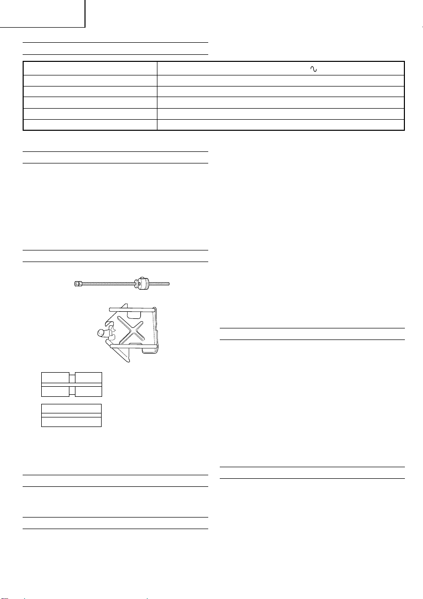
Feed screw
Rod ass’y (Nuts, Rod)
Roller
Wing bolt (A)
Guide bar
Dust Collector set
Knopfschrauben
Handgriffknopf
Lockern
Anziehen
Skala
Den Knopf losdrehen
Den Handgriffknopf lösen
Nach unten drücken
Nach unten drücken
Mutter
Schraube
Skala ablesen
Einstellen der Frästiefe
Führungsstangen
Flügelschrauben
Verriegelungsfeder
Führungsfläche
Behelfsmäßige Holzführung
Schablonenführung
Fräse
Schablone
Abstand
Abstand
Vorschub der Oberfräse
Vorschub der Oberfräse
Werkstück
Drehrichtung der Fräse
Vorschub der Oberfräse
Drehrichtung der Fräse
Richtung, in die die Oberfräse
gedreht wird
Vorschubspindel
Stab (Mutter, Stange)
Rolle
Flügelschraube (A)
Führungsstange
Staubfängersatz
Boulons à tête ronde
Bouton de la poignée
Desserrer
Serrer
Echelle
Desserrer le bouton
Desserrer le bouton de la
poignée
Appuyer vers le bas
Appuyer vers le bas
Ecrou
Vis
Lecture de l’echelle
Réglage de la profondeur de
coupe
Barres de guidage
Boulons à oreilles
Ressort de verrouillage
Surface de guidage
Pièce de guidage auxiliaire en
bois
Guide-gabarit
Couteau
Gabarit
Séparation
Séparation
Avance de la défonceuse
Avance de la défonceuse
Pièce travaillée
Rotation du couteau
Avance de la défonceuse
Rotation du couteau
Forceagissant sur la
défonceuse
Vis-mètre
Emsemble Tige (Écrous, Tige)
Rouleau
Boulon à oreilles (A)
Barre de guidage
Ensemble de récupérateur à poussière
3
Page 6

English
1
2
3
4
5
6
7
8
9
0
A
B
C
D
E
F
G
H
I
J
K
L
M
N
O
P
Q
R
S
T
U
V
W
X
Y
Z
Italiano Nederlands Español
Bulloni a testa tronco-conica
Bullone della maniglia
Allentare
Serrare
Scala
Allentare la manopola
Allentare il bullone della
maniglia
Spingere verso il basso
Spingere verso il basso
Dado
Vite
Leggere la scala
Regolare la profondità di taglio
Barre di guida
Dadi a galletto
Molla di blocco
Superficie di guida
Guida supplementare di legno
Guida per sagoma
Punta
Sagoma
Scostare
Scostare
Avanzamento della fresatrice
verticale
Avanzamemto della fresatrice
verticale
Pezzo da lavorare
Rotazione della punta
Avanzamento della fresatrice
verticale
Rotazione della punta
Senso in cui la fresatrice
verticale viene spinta
Vite d’avanzamento
Meccanismo a tondino (Dadi,
Tondino)
Rullo
Bullone a galletto (A)
Barra di guida
Corredo raccolta polvere
Knopbout
Hendelknop
Losdraaien
Vastdraaien
Schaal
De knop losdraaien
Draai de hendelknop los
Naar beneden drukken
Naar beneden drukken
Moer
Schroef
Schaal aflezen
Het instellen van de
freesdiepte
Leidstang
Vleugelmoer
Borgveer
Leidvlak
Geimproviseerde houtgeleider
Sjablonegeleider
Frees
Sjablone
Afstand
Afstand
Voorschuifinrichting van de
frees
Voorschuifinrichting van de
frees
Werkstuk
Draairichting van de frees
Voorschuifinrichting van de
frees
Draairichting van de frees
Richting, waarin de frees
gedreven wordt
Voorschuifas
Staaf (Moeren, Stang)
Rol
Vleugelmoer (A)
Leidstang
Stofvanger set
Pasadores de perilla
Perilla de asidero
Soltar
Apretar
Escala
Soltar el botón
Soltar la perilla de asidero
Apretar hacia abajo
Apretar hacia abajo
Contratuerca
Tornillo
Anotar la escala
Ajustar la profundidad de corte
Barras de guía
Pasadores de palomilla
Resorte de cierre
Superficie de guía
Guía auxiliar de madera
Guía patrón
Broca
Patrón
Separado
Separado
Alimentación de la ranuradora
Alimentación de la ranuradora
Pieza de trabajo
Rotación de la broca
Alimentación de la ranuradora
Rotación de la broca
Dirección en que es forzada la
ranuradora
Tornillo de alimentación
Caña conjunto (Contratuercas,
Caña)
Rodillo
Pasador de palomilla (A)
Barra de guía
Equipo recolector de polvo
4
Page 7

English
GENERAL OPERATIONAL PRECAUTIONS
WARNING! When using electric tools, basic safety
precautions should always be followed to reduce the risk
of fire, electric shock and personal injury, including the
following.
Read all these instructions before operating this product
and save these instructions.
For safe operations:
1. Keep work area clean. Cluttered areas and benches
invite injuries.
2. Consider work area environment. Do not expose
power tools to rain. Do not use power tools in
damp or wet locations. Keep work area well lit.
Do not use power tools where there is risk to
cause fire or explosion.
3. Guard against electric shock. Avoid body contact
with earthed or grounded surfaces. (e.g. pipes,
radiators, ranges, refrigerators).
4. Keep children away. Do not let visitors touch the
tool or extension cord. All visitors should be kept
away from work area.
5. Store idle tools. When not in use, tools should
be stored in a dry, high or locked up place, out
of reach of children.
6. Do not force the tool. It will do the job better and
safer at the rate for which it was intended.
7. Use the right tool. Do not force small tools or
attachments to do the job of a heavy duty tool.
Do not use tools for purposes not intended; for
example, do not use circular saw to cut tree
limbs or logs.
8. Dress properly. Do not wear loose clothing or
jewelry, they can be caught in moving parts.
Rubber gloves and non-skid footwear are
recommended when working outdoors. Wear
protecting hair covering to contain long hair.
9. Use eye protection. Also use face or dust mask
if the cutting operation is dusty.
10. Connect dust extraction equipment.
If devices are provided for the connection of dust
extraction and collection facilities ensure these are
connected and properly used.
11. Do not abuse the cord. Never carry the tool by
the cord or yank it to disconnect it from the
receptacle. Keep the cord away from heat, oil and
sharp edges.
12. Secure work. Use clamps or a vise to hold the
work. It is safer than using your hand and it frees
both hands to operate tool.
13. Do not overreach. Keep proper footing and balance
at all times.
14. Maintain tools with care. Keep cutting tools sharp
and clean for better and safer performance. Follow
instructions for lubrication and changing
accessories. Inspect tool cords periodically and if
damaged, have it repaired by authorized service
center. Inspect extension cords periodically and
replace, if damaged. Keep handles dry, clean, and
free from oil and grease.
15. Disconnect tools. When not in use, before servicing,
and when changing accessories such as blades,
bits and cutters.
16. Remove adjusting keys and wrenches. Form the
habit of checking to see that keys and adjusting
wrenches are removed from the tool before turning
it on.
17. Avoid unintentional starting. Do not carry a
plugged-in tool with a finger on the switch. Ensure
switch is off when plugging in.
18. Use outdoor extension leads. When tool is used
outdoors, use only extension cords intended for
outdoor use.
19. Stay alert. Watch what you are doing. Use common
sense. Do not operate tool when you are tired.
20. Check damaged parts. Before further use of the
tool, a guard or other part that is damaged should
be carefully checked to determine that it will
operate properly and perform its intended function.
Check for alignment of moving parts, free running
of moving parts, breakage of parts, mounting and
any other conditions that may affect its operation.
A guard or other part that is damaged should be
properly repaired or replaced by an authorized
service center unless otherwise indicated in this
handling instructions. Have defective switches
replaced by an authorized service center. Do not
use the tool if the switch does not turn it on and
off.
21. Warning
The use of any accessory or attachment, other
than those recommended in this handling
instructions, may present a risk of personal injury.
22. Have your tool repaired by a qualified person.
This electric tool is in accordance with the relevant
safety requirements. Repairs should only be carried
out by qualified persons using original spare parts.
Otherwise this may result in considerable danger
to the user.
PRECAUTIONS ON USING ROUTER
1. Single-hand operation is unstable and dangerous.
Ensure that both handles are gripped firmly during
operation.
2. The bit is very hot immediately after operation.
Avoid bare hand contact with the bit for any reason.
5
Page 8
English
SPECIFICATIONS
Voltage (by areas)* (110V, 115V, 120V, 127V, 220V, 230V, 240V)
Power input 550W*
No-load speed 27000/min
Collet chuck capacity 8mm or 6.35mm(1/4") or 6mm
Main body stroke 52mm
Weight 2.3kg (without cord and standard accessories)
*Be sure to check the nameplate on product as it is subject to change by areas.
STANDARD ACCESSORIES
(1) Parallel Guide Ass’y ................................................... 1
(2) Template Guide .......................................................... 1
(3) Wrench ........................................................................2
(4) Screws (for mounting the nameplate guide) ...........2
One scale, one knob screw, two wing bolts, and two lock
springs are packaged together with the standard
accessories (2), (3), and (4) mentioned above.
Standard accessories are subject to change without
notice.
OPTIONAL ACCESSORIES-sold separately
1. Feed Screw Assembly
2. Trimmer Guide Assembly
3. Chuck Sleeve
8 × 6 Chuck Sleeve
8 × 6.35 Chuck Sleeve
4. Collet
8mm, 6.35mm, 6mm
5. Dust Collector set (Fig. 21Z)
Optional accessories are subject to change without notice.
APPRICATIONS
䡬 Woodworking jobs centered on grooving and
chamfering.
PRIOR TO OPERATION
1. Power source
Ensure that the power source to be utilized conforms
to the power requirements specified on the product
nameplate.
6
2. Power switch
Ensure that the power switch is in the OFF position.
If the plug is connected to a receptacle while the
power switch is in the ON position, the power tool
will start operating immediately, which could cause
a serious accident.
3. Extension cord
When the work area is removed from the power
source, use an extension cord of sufficient thickness
and rated capacity. The extension cord should be
kept as short as practicable.
4. Attach the power tool to the holder
Ensure that the power tool is securely fixed to the
holder.
CAUTION
If it is not, it will be very dangerous.
The power tool can be securely fixed by tightening
the holder’s knob bolt. (Fig. 1)
5. Installing the handle knob
To install the handle knob, screw it into the holder
fixing hole securely. (Fig. 1)
MOUNTING AND DISMOUNTING BITS
1. Mounting Bits
(1) After fully inserting the bit into the collet chuck
hole, firmly tighten the collet chuck with the
accessory wrenches, as shown in Fig. 2.
CAUTION
Ensure that the collet chuck is firmly tightened after
inserting the bit. Failure to do so will result in
damage to the collet chuck.
(2) Use a proper bit which has the same diameter as
the collet.
2. Dismounting Bits
To dismount the bit, follow the mounting procedures
in reverse, starting with loosening the collet chuck
with the accessory wrenches.
HOW TO USE THE ELECTRIC ROUTER
1. Adjusting the cutting depth
(1) Adjusting the cutting depth with the scale:
1 Loosen the knob to have the scale move freely.
(Fig. 3)
2 As shown in Fig. 4 loosen the knob ass’y, push
downward on the handles until the bit lightly
contacts the sruface of the material, and reclamp
the knob ass’y. This preliminary setting is called
“cut 0 (zero)”.
3 Next, read the scale on the holder.
Pull the scale up to the desired cutting depth,
then tighten the knob (Fig. 5).
Page 9

English
For example, if a cutting depth of 10mm is desired
and the “cut 0” reading is as shown in Fig. 5
(a), raise the stopper pole arrow to the position
shown in Fig. 5 (b).
(2) With the scale set as described above, loosen the
knob ass’y and push downward on the handles until
the scale contacts the base.
The router is now adjusted to the desired cutting
depth.
(3) It is possible to decrease the clearance between the
bit tip and the material by loosening and moving
downward the nut on the screw.
This step provides convenience when moving the
router to align the bit with the cutting place.
(4) When adjusting the cutting depth without using the
scale, force the scale upward to prevent it from
getting in the way.
2. Guiding the Router
There are several ways of guiding the router. Select
the method most convenient for your work
requirements.
(1) Parallel Guide Ass’y
Use the parallel guide ass’y for chamfering along
the material side or for grooving.
To properly mount the parallel guide ass’y on the
router, first of all, as shown in Fig. 6, attach the
two wing bolts and the two lock springs to the
screw holes on the top side of the base. Insert the
guide bars in the holes on the base and adjust the
distance from the bit to the guide surface.
Tighten the two wing bolts to secure the parallel
guide ass’y.
Feed the router in a manner that the guide surface
of the parallel guide ass’y moves along the material
side.
An auxiliary wood guide can be mounted on the
parallel guide assembly, as shown in Fig. 7, and
fixed in position by utilizing the holes on the guide
surface.
(2) Template Guide
Use the template guide when employing a template
for producing a large quantity of identically shaped
products.
As shown in Fig. 8, secure the template guide to
the base of the router with two accessory screws.
At this time, ensure that the projection side of the
template guide is facing the bottom surface of the
base of the router.
A template is a profiling mold made of plywood
or thin lumber. When making a template, pay
particular attention to the matters described below
and illustrated in Fig. 9.
When using the router along the interior plane of
the template, the dimensions of the finished product
will be less than the dimensions of the template
by an amount equal to dimension “A”, the distance
between the edge of the template and the edge of
the bit. The reverse is true when using the router
along the exterior of the template.
Secure the template to the material. Feed the router
in a manner that the template guide moves along
the template as shown in Fig. 10.
(3) Router Base
Use of the router base as a guide is highly convenient
when working on material with dimensions too
large for use of the parallel guide assembly.
As shown in Fig. 11, secure a straight piece of board
(to be used as a guide) in the appropriate position
on the material, and feed the router in a manner
that the flat side of the router base moves along
the board guide.
Similarly, it is possible to process the material by
guiding the curved side of the router base along
a large dimension template as shown in Fig. 12.
(4) Bits with Pilot
A bit with a pilot is a bit with a rounded shaft with
no cutting edges on its lower portion. Feed the
router by sliding the pilot along the side of the
material as shown in Fig. 13.
3. Cutting
(1) Turn the switch to the ON position while the bit
is separated from the material as shown in Figs.
14 and 15. Do not start cutting operation until the
bit has reached full rotating speed.
(2) The bit rotates clockwise (arrow direction indicated
on the end bracket). To obtain maximum cutting
effectiveness, feed the router in conformance with
the feed directions shown in Fig. 16.
(3) As illustrated in Fig. 17, when the router is feed
in the direction indicated by the black arrow, a
certain force acts on the routher that causes it to
move in the direction indicated by the white arrow.
During operation, be sure to guide the router so
that it does deviate from the desired cutting line.
HOW TO USE THE OPTIONAL ACCESSORIES
1. Feed screw assembly
By using the feed screw assembly, the distance
between the bit and the parallel guide assembly or
trimmer guide assembly can be finely adjusted. As
shown in Fig. 18, attach the feed screw to the
parallel guide assembly or trimmer assembly, and
attach the rod to the base with the provided nuts.
Fine adjustment can be achieved by turning the
feed screw. Pushing the button on the feed screw
will release the grip of the screw and permit fast
movement of the guide assembly.
2. Trimmer guide assembly
Suitable for trimming, beveling or working the inner
surface of furniture or house fittings with plywood
or veneer surfaces. Insert the assembly guide bars
into the holes of the base, adjust the distance
between the bit and roller as desired, and tighten
the wing bolts on the base to fix the trimmer in
position. Then, loosen the wing bolt (A), shown in
Fig. 19, and set the roller to the appropriate position.
Ensure that the wing bolt (A), is firmly retightened
before using the machine, as shown in Fig. 20.
3. Chuck Sleeve
When using the 6mm or 6.35 mm ø bit for a collet
with an inner diameter of 8mm, you need the 8
× 6 or 8 × 6.35 chuck sleeve, respectively.
CAUTION
8 × 6 chuck sleeve is equipped with a groove, while
the 8 × 6.35 is not. Never use a 6mm ø shaft bit
with an 8 × 6.35 chuck sleeve, or a 6.35mm ø shaft
bit with an 8 × 6 chuck sleeve.
7
Page 10

English
Deutsch
4. Collet
Use the proper collet according to the diameter of
the bit used.
5. Dust collector Set (Fig. 21Z)
Connect the dust collector set (Fig. 21Z) cleaner
to collect dust.
MAINTENANCE AND INSPECTION
1. Oiling
To ensure smooth vertical movement of the router,
occasionally apply a few drops of machine oil to
the sliding portions of the columns and end bracket.
2. Inspecting the mounting screws:
Regurarly inspect all mounting screws and ensure
that they are properly tightened. Should any of the
screws be loose, retighten them immediately. Failure
to do so could result in serious hazard.
3. Maintenance of the motor
The motor unit winding is the very “heart” of the
power tool. Exercise due care to ensure the winding
does not become damaged and/or wet with oil or
water.
4. Servicing
Consult an authorized service agent in the event of
power tool failure.
NOTE
Due to HITACHI’s continuing program of research and
development, the specifications herein are subject to
change without prior notice.
IMPORTANT
Correct connection of the plug
The wires of the main lead are coloured in accordance
with the following code:
Blue: -Neutral
Brown: -Live
As the colours of the wires in the main lead of this tool
may not correspond with the coloured markings
identifying the terminals in your plug proceed as follows:
The wire coloured blue must be connected to the terminal
marked with the letter N or coloured black. The wire
coloured brown must be connected to the terminal marked
with the letter L or coloured red.
Neither core must be connected to the earth terminal.
NOTE
This requirement is provided according to BRITISH
STANDARD 2769: 1984.
Therefore, the letter code and colour code may not be
applicable to other markets except The United Kingdom.
Information concerning airborne noise and vibration
The measured values were determined according to
EN50144.
The typical A-weighted sound pressure level: 84 dB (A)
Wear ear protection.
The typical weighted root mean square acceleration value:
2
4.0 m/s
.
ALLGEMEINE VORSICHTSMASSNAHMEN
WARNUNG! Bei der Verwendung von Elektrowerkzeugen
müssen immer die grundlegenden Vorsichtsmaßnahmen
befolgt werden, um das Risiko von Feuer, elektrischem
Schlag und persönlicher Verletzung und den
nachfolgenden Punkten zu vermeiden.
Lesen Sie diese Anweisungen völlig, bevor Sie dieses
Erzeugnis verwenden, und bewahren Sie diese
Anweisungen auf.
Für sicheren Betrieb:
1. Der Arbeitsplatz sollte sauber gehalten werden.
Unaufgeräumte Arbeitsplätze und Werkbänke
erhöhen die Unfallgefahr.
2. Die Betriebsbedingungen beachten.
Elektrowerkzeuge sollten nicht dem Regen
ausgesetzt werden.
Ebenfalls sollten Sie nicht an feuchten oder nassen
Plätzen gebraucht werden.
Der Arbeitsplatz sollte gut beleuchtet sein.
Verwenden Sie Elektrowerkzeuge nicht an Orten,
an denen die Gefahr von Feuer oder Explosion
besteht.
3. Schutzmaß nahmen gegen elektrische Schläge
treffen. Darauf achten, daß das Gehäuse nicht in
Kontakt mit geerdeten Flachen kommt, z. (z.B.
Rohre, Radiatoren, Elektroherde, Kühlschränke).
4. Kinder sollten vom Gerät ferngehalten werden.
Vermeiden, daß andere Personen mit dem
Werkzeung oder Verlängerungskabel in Kontakt
kommen.
5. Nicht benutzte Werkzeuge sollten sicher aufbewahrt
werden. Sie sollten an einem trockenen und
verschließbaren Ort aufbewahrt werden, damit
Kinder sie nicht in die Hände bekommen.
6. Werkzeuge sollten nicht mit übermäßiger Gewalt
verwendet werden. Ihre Leistung ist besser und
sicherer, wenn sie mit der vorgeschriebenen
Geschwindigkeit verwendet werden.
7. Nur die korrekten Werkzeuge verwenden. Niemals
ein kleineres Werkzeug oder Zusatzgerat für
Arbeiten verwenden, die Hochleistungsgerate
erfordern. Nur Werkzeuge verwenden, die dem
Verwendungszweck entsprechen, d.h. niemals eine
Kreissäge zum Sägen von Ästen oder
Baumstämmen verwenden.
8. Die richtige Kleidung tragen. Keine lose Kleidung
oder Schmuck tragen, da sich lose Kleidungsstücke
in den bewegenden Teilen verfangen kònnen. Bei
Arbeiten im Freien sollten Gummihandschuhe und
rutschfeste Schuhe getragen werden.
9. Es sollte eine Sicherheitsbrille getragen werden.
Bei Arbeiten mit Staubentwicklung sollte eine
Gesichtsoder Staubmaske getragen werden.
10. Schließen Sie eine Staubabsaugvorrichtung an.
Wenn Vorrichtungen für den Anschluß von
Staubabsaug- und -sammelvorrichtungen
vorhanden sind, so stellen Sie sicher, daß diese
angeschlossen sind und richtig verwendet werden.
11. Niemals das Kabel mißbrauchen. Ein Werkzeug
niemals am Kabel tragen oder bei Abtrennung
von der Steckdose das Kabel harausreißen. Das
Kabel sollte gegen Hitze, Öl und scharfe Kanten
geschützt werden.
12. Den Arbeitsplatz gut absichern. Zwingen oder einen
Schraubstock zur Befestigung des Werkstücks
verwenden. Das ist sicherer als die Benutzung der
Hände und macht beide Hände zur Bedienung des
Werkzeugs frei.
8
Page 11

Deutsch
13. Sich niemals weit überbeugen. Immer einen festen
Stand und ein sicheres Gleichgewicht bewahren.
14. Die Werkzeuge sollten sorgfältig behandelt werden.
Für einen einwandfreien und sicheren Betrieb
sollten sie stets scharf sein und saubergehalten
werden. Die Anleitungen für schmierung und
Austausch des Zuehörs unbedingt einhalten. Die
Kabel der Geräte regelmäßig überprüfen und bei
Beschädigung durch eine autorisierte
Kundendienststelle reparieren lassen.
Ebenfalls die Verlägerungskabel regelmäßig
überprüfen und bei Beschadigung auswechseln.
Die Handgriffe sollten stets trocken und sauber
sein, sowie keine Ol- oder Schmierfett stellen
aufweisen.
15. Werkzeuge vom Netz trennen, wenn sie nicht
benutzt werden, vor Wartungsarbeiten und beim
Austausch von Zubehörteilen wie z.B. Blätter,
Bohrer und Messer.
16. Alle Stellkeile und Schraubenschlüssel entfernen.
Vor Einschaltung des Gerätes darauf achten, daß
alle Stellkeile und Schraubenschlüssel entfernt
worden sind.
17. Ein unbeabsichtigtes Einschalten sollte vermieden
werden. Niemals ein angeschlossenes Werkzeug
mit dem Finger am Schalter tragen. Vor Anschluß
überprüfen, ob das Gerät ausgeschaltet ist.
18. Im Freien ein Verlängerungskabel verwenden. Nur
ein Verlängerungskabel verwenden, das für die
Verwendung im Freien markiert ist.
19. Den Arbeitsvorgang immer unter Kontrolle haben.
Das Gerät niemals in einem abgespannten Zustand
verwenden.
VORSICHTSMASSNAHMEN BEI DER
VERWENDUNG DER OBERFRÄSE
1. Einhändiges Arbeiten ist unstabil und gefährlich.
Man muß darauf achten, daß das Werkzeug während
des Betriebs mit beiden Händen gut festgehalten
wird.
2. Die Fräse ist unmittelbar nach dem Arbeiten sehr
heiß. Ein Berühren der Fräse ist aus diesem Grunde
zu vermeiden.
20. Beschädigte Teile überprüfen. Vor Benutzung des
Werkzeugs sollten beschädigte Teile oder
Schutzvorrichtungen sorgfältig überprüft werden,
um festzustellen, ob sie einwandfrei funktionieren
und die vorgesehene Funktion erfüllen,
Ausrichtung, Verbindungen sowie Anbringung sich
bewegender Teile überprüfen. Ebenfalls
uberprufen, ob Teile gebrochen sind. Teile oder
Schutzvorrichtungen, die beschädigt sind, sollten,
wenn in dieser Bedienungsanleitung nichts anderes
erwähnt ist, durch eine autorisierte
Kundendienststelle ausge wechselt oder repariert
werden. Dasselbe gilt für defekte Schalter.
Wenn sich das Werkzeug nicht mit dem Schalter
einoder ausschalten läßt, sollte das Werkzeug nicht
verwendet werden.
21. Warnung
Die Verwendung von anderem Zubehör oder
anderen Zusätzen als in dieser Bedienungsanleitung empfohlen kann das Risiko einer
Körperverletzung einschließen.
22. Lassen Sie Ihr Werkzeug durch qualifiziertes
Personal reparieren. Dieses Elektrowerkzeug
entspricht den zutreffenden Sicherheitsanforderungen. Reparaturen sollten nur von
qualifiziertem Personal unter Verwendung von
Originalersatzteilen durchgeführt werden, da sonst
beträchtliche Gefahr für den Benutzer auftreten
kann.
TECHNISCHE DATEN
Spannung (je nach Gebiet)* (110V, 115V, 120V, 127V, 220V, 230V, 240V)
Leistungsaufnahme 550W*
Leerlaufdrehzahl 27000/min
Spannfutter spannt bis 8mm oder 6,35mm (1/4") oder 6mm
Hubhöhe 52mm
Gewicht 2,3 (ohne Kabel und Standardzubehör)
*Vergessen Sie nicht, die Produktangaben auf dem Typenschild zu überprüfen, da sich diese je nach Verkaufsgebiet
ändern.
9
Page 12

Deutsch
STANDARZUBEHÖR
(1) Parallelanschlag ......................................................... 1
(2) Schablonenführung ................................................... 1
(3) Schraubenschlüssel ................................................... 2
(4) Schrauben (zum Befestigen der
Schablonenführung) .................................................. 2
Eine Skala, eine Knopfschraube, zwei Flügelschrauben
und zwei Verriegelungsfedern sind zusammen mit dem
oben angeführten Standardzubehör (2), (3) und (4)
verpackt.
Das Standardzubehör kann ohne vorherige
Bekanntmachung jederzeit geändert werden.
SONDERZUBEHÖR-separat zu beziehen
1. Vorschubspindelvorrichtung
2. Führung für Zurichten
3. Futterhülse
8 × 6 Futterhülse
8 × 6,35 Futterhülse
4. Manschette
8mm, 6,35mm, 6mm
5. Staubfängersatz (Abb. 21Z)
Das Sonderzubehör kann ohne vorherige
Bekanntmachung jederzeit geändert werden.
ANWENDUNG
䡬 Holzarbeiten, speziell Nutherstellung und Abfasen.
VOR INBETRIEBNAHME
1. Netzspannung
Prüfen, daß die zu verwendende Netzspannung der
Angabe auf dem Typenschild entspricht.
2. Netzschalter
Prüfen, daß der Netzschalter auf “AUS” steht. Wenn
der Stecker an das Netz angeschlossen wird,
während der Schalter auf “EIN” steht, beginnt das
Werkzeug sofort zu laufen, was gefährlich ist.
3. Verlängerungskabel
Wenn der Arbeitsbereich nicht in der Nähe des
Netzanschlusses liegt, ist ein Verlängerungskabel
ausreichenden Querschnitts und ausreichender
Nennleistung zu verwende. Das Verlängerungskabel
sollte so kurz wie möglich gehalten werden.
4. Das elektrische Werkzeug am Halter anbringen.
Sicherstellen, daß das Werkzeug sicher am Halter
befestigt ist. Wenn das nicht der Fall ist, besteht
Unfallgefahr.
ACHTUNG
Das Werkzeug kann durch Festziehen der
Halteknopfschraube (Abb. 1) befestigt werden.
5. Installieren des Handgriffknopfs
Schrauben Sie den Handgriffknopf zum Installieren
sicher in das Halterbefestigungsloch (Abb. 1)
ANBRINGEN UND ENTFERNEN DER FRÄSEN
1. Anbringen der Fräsen
(1) Wenn die Fräse ganz in das Loch de Spannfutters
eingesetzt ist, wird das Spannfutter mit den
Schraubenschlüsseln entsprechend Abb. 2
festgezogen.
ACHTUNG
Es ist darauf zu achten, daß das Spannfutter nach
dem Einsetzen der Fräse gut angezogen ist.
Geschieht das nicht, führt das zu einer Beschädigung
des Spannfutters.
(2) Eine geeignete Frässpitze verwenden, die den
gleichen Durchmesser wie die Manschette hat.
2. Entfernen der Fräsen
Zum Entfernen der Fräse wird in umgekehrter
Reihenfolge vorgegangen. Wobei mit dem Lockern
des Spannfutters mit den Schraubenschlüsseln
begonnen wird.
FINSATZ DER OBERFRÄSE
1. Einstellen der Frästiefe
(1) Einstellen der Frästiefe mit Skala.
1 Den Knopf lösen, um freie Skalabewegung zu
ermöglichen (Abb. 3).
2 Wie in Abb. 4 gezeigt wird der Griffknopf gelöst,
die Handgriffe nach unten gedrückt, bis die Fräse
die Oberfläche des Werkstückes berührt und der
Griffknopf wieder festgeklemmt. Diese vorläufige
Einstellung wird als “Schnitt 0 (null)” bezeichnet.
3 Die Skala auf dem Halter ablesen.
Die Skala auf die gewünschte Frästiefe einstellen
und dann den Knopf festziehen (Abb. 5).
Wenn z.B. eine Frästiefe von 10mm gewünscht
wird und die Anzeige bei “Schnitt 0” der Anzeige
in Abb. 5 (a) entspricht, wird der Pfeil auf dem
Anschlagstift auf die in Abb. 5 (b) gezeigte
Position nach oben verschoben.
(2) Nachdem die Skala wie vorstehend beschrieben
eingestellt ist, wird der Griffknopf gelockert und die
Handgriffe nach unten gedrückt, bis die Skala den
Anschlagblock oder die Einstellschraube für die
gewünschte Frästiefe berührt. Damit ist die Oberfräse
auf die gewünschte Frästiefe eingestellt.
(3) Es ist möglich, den Abstand zwischen der Frässpitze
und dem Werkstück zu verringern, indem die Mutter
an der Schraube gelockert und nach unten gedreht
wird.
Dieser Schritt bietet Erleichterung, wenn die
Oberfräsmaschine bewegt wird, um die Fräse auf
die Frässtelle auszurichten.
(4) Beim Einstellen der Frästiefe ohne Skala wird die
Skala nach oben geschoben, damit sie nicht stört.
2. Führung der Oberfräse
Es gibt verschiedene Möglichkeiten, die Oberfräse
10
Page 13

Deutsch
zu führen. Man wählt die Methode aus, die für die
durchzuführende Arbeit am besten geeignet ist.
(1) Parallelanschlag
Der Parallelanschlag wird für das Abfasen oder für
Nutfräsen verwendet.
Bringen Sie zuerst die zwei Flügelschrauben und die
zwei Verriegelungsfedern wie in Abb. 6 gezeigt an
den Gewindelöchern an der Oberseite der Basis an.
Schieben Sie die Führungsstangen in die Löcher in
der Basis, und stellen Sie den Abstand zwischen
der Fräse und der Führungsoberfläche ein.
Ziehen Sie die beiden Flügelschrauben an, um den
Parallelanschlag zu sichern.
Die Oberfräse wird so vorgeschoben, daß die
Führungsfläche des Parallelanschlages sich an der
Kante des Werkstückes entlang bewegt.
Am Parallelanschlag kann eine Zusatzholzführung,
wie in Abb. 7 gezeigt, angebracht und mittels der
Löcher an der Führungsfläche befestigt werden.
(2) Schablonenführung:
Die Schablonenführung wird verwendet, wenn für
die Herstellung einer großen Zahl gleichgeformter
Teile eine Schablone verwendet wird.
Gemäß Abb. 8 wird die Schablonenführung an der
Grundplatte der Oberfräse mit zwei Schrauben
befestigt. Hierbei ist darauf zu achten, daß die
vorspringende Seite der Schablonenführung zur
Unterseite der Grundplatte der Oberfräsmaschine
gerichtet ist. Eine Schablone ist eine Profilform aus
Sperrholz oder dünnem Holz. Bei der Herstellung
einer Schablone ist besonders auf die nachstehenden
Hinweise und die Abb. 9 zu achten. Wenn die
Oberfräse an der Innenseite der Schablone
entlanggeführt wird, sind die Abmessungen des
bearbeiteten Stückes geringer als die Abmessungen
der Schablone, und zwar um das mit “A”
gekennzeichnete Stück, das dem Abstand zwischen
der Kante der Schablone und der Kante der Fräse
entspricht. Wenn die Oberfräse an der Außenseite
der Schablone entlanggeführt wird, ist das
Umgekehrte der Fall.
Die Schablone ist am Werkstück befestigt. Die
Oberfräse ist so vorzuschieben, daß sich die
Schablonenführung an der Schablone entlang
bewegt, wie in Abb. 10 gezeigt.
(3) Grundplatte
Die Verwendung der Grundplatte der Oberfräse als
Führung ist beim Arbeiten an einem Werkstück,
dessen Abmessungen für die Benützung des
Parallelanschlages zu groß ist, erforderlich.
Wie in Abb. 11 dargestellt, wird ein gerades Stück
Holz (das als Führung zu benutzen ist) an einer
geeigneten Stelle auf dem Werkstück angebracht
und die Oberfräse so vorgeschoben, daß sich die
flache Seite der Oberfräse an dem Brett entlang
bewegt.
Es ist ebenso möglich, ein Werkstück zu bearbeiten,
indem die runde Seite der Grundplatte der Oberfräse
an einer Schablone mit großem Durchmesser
entlanggeführt wird, wie in Abb. 12 gezeigt.
(4) Fräsen mit Führungszapfen
Eine Fräse mit einem Führungszapfen ist eine Fräse
mit einem abgerundeten Schaft ohne Schneidkanten
am unteren Teil. Die Oberfräse wird vorgeschoben,
wobei der Führungszapfen an der Seite des
Werkstückes entlanggleitet, wie in Abb. 13 gezeigt.
3. Fräse
(1) Die Maschine wird eingeschaltet, wenn die Fräse
das Werkstück noch nicht berührt, wie in den Abb.
14 und 15 gezeigt. Die Fräsarbeit darf erst begonnen
werden, wenn die Fräse die volle
Umdrehungsgeschwindigkeit erreicht hat.
(2) Die Fräse dreht sich im Uhrzeigersinn (entsprechend
der Pfeilrichtung am offenen Lagerschild). Zur
Erreichung einer maximalen Fräsleistung wird die
Oberfräse in den in Abb. 16 angegebenen
Vorschubrichtungen bewegt.
(3) In Abb. 17 ist dargestellt, daß, wenn die Oberfräse
in die durch den schwarzen Pfeil gekennzeichnete
Richtung vorwärts bewegt wird, auf die Fräse eine
gewisse Kraft einwirkt, durch die sie in die durch
den weißen Pfeil gekennzeichnete Richtung treibt.
Während der Arbeit ist darauf zu achten, daß die
Oberfräse so geführt wird, daß sie nicht von der
gewünschten Fräsrichtung abweicht.
VERWENDUNG DES SONDERZUBEHÖRS
1. Vorschubspindelvorrichtung
Durch Benützung der Vorschubspindelvorrichtung
kann der Abstand zwischen der Fräse und dem
Parallelanschlag oder der Zurichtführung fein
eingestellt werden.
Wie in Abb. 18 gezeigt, wird die Vorschubspindel
an dem Parallelanschlag oder der Zurichtvorrichtung
befestigt und die Stange an der Grundplatte mit den
vorgesehenen Muttern befestigt. Die Feineinstellung
kann durch Drehen der Vorschubspindel erreicht
werden. Durch Drücken des Knopfes an der
Vorschubspindel wird der Griff der Schraube
freigegeben und eine schnelle Bewegung der
Führungsvorrichtung möglich.
2. Zurichtführung
Geeignet zum Zurichten, Abkanten und Bearbeiten
der Innenflächen von Möbeln oder Armaturen mit
Sperrholz oder Furnierflächen. Die Führungsstangen
der Vorrichtung werden in die Löcher der
Grundplatte eingesteckt, der Abstand zwischen der
Fräse und der Rolle nach Wunsch eingestellt und
die Flügelschrauben an der Grundplatte angezogen,
um die Zurichtmaschine in der Position zu fixieren.
Dann wird die Flügelschraube (A), die in Abb. 19
gezeigt ist, gelockert und die Rolle in die geeignete
Position gestellt. Es ist darauf zu achten, daß die
Flügelschraube (A) vor Benützung der Maschine
wieder fest angezogen wird, wie in Abb. 20 gezeigt.
3. Futterhülse
Bei Verwendung von Frässpitzen mit 6mm oder
6,35mm Durchmesser für eine Manschette mit einem
Innendurchmesser von 8mm wird eine 8 × 6
beziehungsweise 8 × 6,35 Futterhülse benötigt.
ACHTUNG
Die 8 × 6 Futterhülse hat eine Rille, während die
8 × 6,35 Futterhülse keine Rille hat. Es darf niemals
eine Fräse mit 6mm Schaftdurchmesser mit einer
8 × 6,35 Futterhülse oder eine Fräse mit 6,35mm
Schaftdurchmesser mit einer 8 × 6 Futterhülse
verwendet werden.
4. Manschette
Immer eine geeignete Maschette je nach
11
Page 14

Deutsch
Français
Durchmesser der verwendeten Frässpitze
verwenden.
5. Staubfängersatz (Abb.21Z)
Den Staubfängersatz (Abb.21Z) Reiniger zum
Auffangen von Staub anbringen.
WARTUNG UND INSPEKTION
1. Ölen
Um eine reibungslose vertikale Bewegung der
Oberfräsmaschine zu gewährleisten, werden
gelegentlich einige Tropfen Maschinenöl auf die
Gleitteile des Ständers und das offene Lagerschild
gegeben.
2. Inspektion der Befestigungsschraube:
Alle Befestigungsschrauben werden regelmäßig
inspiziert und geprüft, ob sie gut angezogen sind.
Wenn sich eine der Schrauben lockert, muß sie
sofort wieder angezogen werden. Geschieht das
nicht, kann das zu erheblichen Gefahren führen.
3. Wartung des Motors:
Die Motorwicklung ist das “Herz” des
Elektrowerkzeugs. Daher ist besonders sorgfältig
darauf zu achten, daß die Wicklung nicht beschädigt
wird und/oder mit Öl oder Wasser in Berührung
kommt.
4. Wartung
Bei Betriebsstörungen des Werkzeuges den
Kundendienst für Ihr Wohngebiet rufen.
ANMERKUNG
Aufgrund des ständigen Forschungs-und
Entwicklungsprogramms von HITACHI sind Änderungen
der hierin gemachten technischen Angaben nicht
ausgeschlossen.
Information über Betriebslärm und Vibration
Die Meßwerte wurden entsprechend EN50144 bestimmt.
Der typische A-gewichtete Schalldruckt ist 84 dB (A).
Bei der Arbeit immer einen Ohrenschutz tragen.
Der typische gewogene quadratische Mittelwert für die
Beschleunigung ist 4,0 m/S
2
.
PRECAUTIONS GENERALES DE TRAVAIL
ATTENTION! Lors de l’utilisation d’un outillage
électrique, les précautions de base doivent être
respectées de manière à réduire les risques d’incendie,
de secousse électrique et de blessure corporelle, y
compris les précautions suivantes.
Lire ces instructions avant d’utiliser le produit et
conserver ces instructions pour référence.
Pour assurer un fonctionnement sûr:
1. Maintenir l’aire de travail propre. Des ateliers ou
des établis en désordre risquent de provoquer des
accidents.
2. Tenir compte de l’environnement de l’aire de tra
vail. Ne pas exposer les outils électriques à la
pluie.
Ne pas les utiliser dans des endroits humides.
Travailler dans un endroit bien éclairé.
Ne pas utiliser d’outillage électrique s’il existe un
risque d’incendie ou d’explosion.
3. Protection contre une décharge électrique. Eviter
tout contact corporel avec des surfaces de mise
à la terre telles que les tuyaux, radiateurs,
cuisinières et réfrigérateurs.
4. Tenir les enfants éloignés. Ne pas laisser les
visiteurs toucher l’outil ou son cordon
d’alimentation. Il est préférable de tenir les visiteurs
à l’écart de l’aire de travail.
5. Ranger les outils non utilisés. Quand on ne les
utilise pas, il est recommandé de ranger les outils
dans un endroit sec, verrouillé ou hors de portée
des enfants.
6. Ne pas forcer l’outil. Il fonctionnera mieux et plus
sûrement à la vitesse pour laquelle il a été con
cu.
7. Utiliser l’outil approprié. Ne pas essayer de faire
avec un petit outil le travail prevu pour un outil
plus important. Toujours utiliser l’outil adéquat;
par exemple, ne pas se servir d’une scie circulaire
pour couper des branches d’arbres ou des billots
de bois.
8. Porter des vêtements appropriés. Ne pas mettre
de vêtements flottants ou de bijoux qui risquent
d’être pris dans les pièces mobiles. Si l’on travaille
à l’extérieur, il est recommandé de porter des
gants de caoutchouc et des chaussures à semelles
antidérapantes. Veiller à s’attacher les cheveux ou
à mettre un bonnet si on a les cheveux longs.
9. Porter des lunettes protectrices. Mettre un masque
si l’opération de coupe crée de la poussière.
10. Relier l’équipement d’extraction de poussière.
Si des dispositifs sont prévus pour le raccordement
d’installations d’extraction et de collection de
poussière, s’assurer qu’ils sont correctement
raccordés et utilisés.
11. Prendre soin du fil. Ne jamais transporter l’outil
en le tenant par le fil et ne pas le débrancher en
tirant sur le fil d’un coup sec. Tenir le fil à l’abri
de la chaleur, l’éloigner de l’huile ou de bords
tranchants.
12. Fixer fermement la piêce à travailler. Utiliser des
agrafes ou un étau pour la maintenir, C’est plus
sûr que d’utiliser ses mains et cela les libêre pour
faire fonctionner l’outil.
12
Page 15

Français
13. Ne pas présumer de ses forces. Essayer de garder
son équilibre en toute circonstance.
14. Entretenir les outils avec soin. Les conserver bien
aiguisés et les nettoyer afin d’en obtenir les
meilleures performances et de pouvoir les utiliser
sans danger. Suivre les instructions pour le
graissage et le changement des accessoires.
Vérifier régulièrement les fils et cordons et s’ils
sont endommagés, les faire réparer par une
personne compétente. Vérifier régulièrement les
rallonges et les remplacer si elles sont
endommagées. Veiller à ce que les poignées soient
toujours sèches et propres, sans huile ni graisse.
15. Debrancher les outils lorsqu’on ne les utilise pas,
avant toute opération d’entretien et lors du
changement d’accessoire; comme par exemple
quand on change les lames, les forets, le fraises,
etc.
16. Retirer les clés de réglage. Prendre l’habitude de
toujours vérifier que les clés de réglage sont bien
retirées de l’appareil avant de le mettre en marche.
17. Eviter toute mise en marche accidentelle. Ne pas
transporter l’outil branché avec un doigt sur
l’interrupteur. S’assurer que l’interrupteur est sur
la position d’arrêt quand on branche l’outil.
18. Utilisation de rallonges à l’extérieur. Quand on
utilise l’outil à l’extérieur, ne se servir que des
rallonges prévues pour l’extérieur et portant une
marque distinctive.
19. Soyez vigilant. Regardez bien ce que vous faites.
Faites appel à votre bon sens. N’utilisez pas l’outil
quand vous êtes fatigué.
20. Vérifier les pièces endommagées. Avant d’utiliser
davantage l’outil, vérifier attentivement toute pièce
endommagée afin de déterminer si l’outil peut
fonctionner correctement et effectuer le travail
pour lequel il est prévu. Vérifier l’alignement et
la flexion des piêces mobiles, la cassure des pièces,
le montage et toute autre condition risquant
d’affecter le bon fonctionnement de l’outil. Un
protecteur ou toute autre pièce endommagée devra
être correctement réparé ou remplacé par un
service d’entretien autorisé, sauf autre indication
dans ce mode d’emploi. Faire remplacer les
interrupteurs défectueux par un service d’entretien
autorisé. Ne pas utiliser l’outil si l’interrupteur ne
permet pas de le mettre en marche ou de l’arrêter.
21. Précaution
L’utilisation d’un accessoire ou dispositif annexe
autre que ceux conseillés dans ce mode d’emploi
peut entraîner un risque de blessure corporelle.
22. Confier la réparation d’un outil à un technicien
qualifié. Cet outil électrique a été conçu
conformément aux règles de sécurité en usage.
Les réparations doivent être effectuées par du
personnel qualifié utilisant des pièces d’origine.
Dans le cas contraire, l’utilisateur s’expose à des
risques graves.
PRECAUTIONS D’UTILISATION DE LA
DÉFONCEUSE
1. Le fonctionnement à une main est instable et
dangereux. Veiller à tenir fermement les deux
poignées pendant le fonctionnement.
2. Le couteau est très chaud aussitôt après le
fonctionnement. Eviter de le toucher à main nue
pour une raison ou pour une autre.
SPECIFICATIONS
Tension (par zone)* (110V, 115V, 120V, 127V, 220V, 230V, 240V)
Puissance 550W*
Vitesse sans charge 27000/min
Capacité du mandrin de serrage 8mm ou 6,35mm (1/4") ou 6mm
Course du corps principal 52mm
Poids 2,3 kg (sans fil et accessoires standard)
*Assurez-vous de vérifier la plaque signalétique sur le produit qui peut changer suivant les régions.
ACCESOIRES STANDARD
(1) Ensemble de guidage parallèle ................................ 1
(2) Guide-gabarit ............................................................. 1
(3) Clef .............................................................................. 2
(4) Vis (pour monter le guide-gabarait) .................... 2
Un gabarit, une vis moletée, deux boulons à oreilles et
deux ressorts de verrouillage sont livrés dans l’emballage
avec les accessoires standard (2), (3) et (4) mentionnés cidessus.
Les accessoires standard sont sujets à changement sans
préavis.
13
Page 16

Français
ACCESSOIRES A OPTION - vedus déparément
1. Ensemble de vis d’avancement
2. Ensemble de guidage pour trancher et dresser
3. Douille de mandrin
Douille de mandrin 8 × 6
Douille de mandrin 8 × 6,35
4. Collet
8mm, 6,35mm, 6mm
5. Ensemble de récupérateur à poussière (Fig. 21Z)
Les accessoires à option sont sujets à changement sans
préavis.
APPLICATIONS
䡬 Travaux du bois à l’accent mis sur la formation de
rainures et de chanfreins.
AVANT LA MISE EN MARCHE
1. Source de puissance
S’assurer que la source de puissance à utiliser
correspond à la puissance indiquée sur la plaque
signalétique du produit.
2. Interrupteur de puissance
S’assurer que l’interrupteur de puissance est en
position ARRET.
Si la fiche est branchée alors que l’interrupteur est
sur MARCHE, l’outil démarre immédiatement et peut
provoquer un grave accident.
3. Fil de rallonge
Lorsque la zone de travail est éloignée de la source
de puissance, utiliser un fil de rallonge d’une
épaisseur suffisante et d’une capacité nominale
suffisante. Le fil de rallonge doit être aussi court
que possible.
4. Fixer la machine outil au support
S’assurer que l’outil est fermement fixé au support,
ceci pour éviter tout risque d’accident.
ATTENTION
Fixer l’outil en serrant le boulon à tête ronde du
support (Fig.1)
5. Installation du bouton de poignée
Pour installer le bouton de poignée, le visser à fond
sur l’orifice de fixation du support. (Fig. 1)
MONTAGE ET DÉMONTAGE DES COUTEAUX
1. Montage des couteaux
(1) Après avoir entièrement introduit le couteau dans
le trou du mandrin de serrage, serrer celui-ci à fond
avec les clefs accessoires suivant la Fig. 2.
ATTENTION
S’assurer que le mandrin de serrage est bien serré
après avoir monté un couteau. Le mandrin de serrage
peut sinon être abîmé.
(2) Utiliser u couteau de même diamètre que le collet.
2. Démontage des couteaux
Pour démonter le couteau, suivre la procédure de
montage en sens inverse, en commençant par le
desserrage du mandrin de serrage avec les clefs
accessoires.
COMMENT UTILISER LA DÉFONCEUSE
1. Réglage de la profondeur de coupe
(1) Réglage de la profondeur de coupe avec l’échelle
1 Desserrer le bouton pour pouvoir déplacer
librement l’échelle (Fig. 3).
2 Suivant la Fig. 4 desserrer le bouton, appuyer
vers le bas sur les poignées jusqu’à ce que le
couteau entre légèrement en contact avec la
surface de la pièce et resserrer le bouton. Ce
réglage préliminaire est appelé “coupe 0” (zéro).
3 Ensuite, lire les données de l’échelle, située sur
le support.
Tirer l’échelle jusqu’à la profondeur de coupe
désirée, puis serrer le bouton (Fig. 5).
Par exemple, si on désirée une profondeur de
coupe de 10mm et si la lecture “coupe 0” est
celle indiquée à la Fig. 5 (a), lever la flèche de
la colonne à la position montrée à la Fig. 5 (b).
(2) Une fois l’échelle réglée suivant la description
cidessus, desserrer le bouton et appuyer vers le bas
sur les poignées jusqu’à ce que l’échelle entre en
contact avec la base. La défonceuse est maintenant
réglée à la profondeur de coupe souhaitée.
(3) Il est possible de réduire le jeu entre la pointe du
couteau et la pièce travaillée en desserrant et en
déplaçant vers le bas l’écrou de la vis. Cette opération
est pratique lorsqu’on déplace la défonceuse pour
aligner le couteau sur l’endroit de coupe.
(4) Pour régler la profondeur de coupe sans utiliser
l’échelle, la remonter pour qu’elle ne gêne pas.
2. Guidage de la défonceuse
Il y a plusieurs possibilités de guider la défonceuse.
Choisir la méthode qui convient le mieux à vos
exigences de travail.
(1) Ensemble de guidage parallèle
Utiliser l’ensemble de guidage parallèle pour la
formation de chanfrein le long de la pièce travaillée
ou pour la formation de rainures.
Pour monter correctement l’ensemble de guidage
parallèle sur la défonceuse, comme indiqué sur la
Fig. 6, fixer tout d’abord les deux boulons à oreilles
et les deux ressorts de verrouillage sur les trous
de vis de la partie supérieure de la base. Introduire
les barres de guidage dans les trous à la base de
la machine, et ajuster la distance entre le couteau
et la surface de guidage. Serrer les deux boulons
à oreilles pour fixer l’ensemble de guidage parallèle.
14
Page 17

Français
Avancer la défonceuse de manière à ce que la
surface de guidage de l’ensemble de guidage
parallèle se déplace le long du côté de la pièce
travaillée.
Un élément de guidage auxiliaire en bois pourra
être monté sur l’ensemble de guidage parallèle,
suivant la Fig. 7 et mis en place en utilisant les
trous de la surface de guidage.
(2) Guide-gabarit
Utiliser le guide-gabarait lorsqu’on utilise un gabarit
pour produire une grande quantité de prodruits de
forme identique.
Suivant la Fig. 8, fixer le guide-gabarit à la base
de la défonceuse avec les deux vis (accessoires).
S’assurer à ce moment que le côté avancé du
gabarit fait face à la surface inférieure de la base
de la défonceuse.
Un gabarit est un moule profilé fait en contreplaqué
ou en bois fin. Lors de la fabrication d’un gabarit,
faire particulièrement attention aux points décrits
ci-dessous et illustrés à la Fig. 9.
Lorsqu’on utilise la défonceuse le long du plan
intérieur du gabarit, les dimensions du produit fini
seront inférieures à celles du gabarit d’une valeur
égale à celle du côté “A”, qui est la distance entre
le bord du gabarit et le bord du couteau. L’inverse
est vrai lorsqu’on utilise la défonceuse le long du
bord extérieur du gabarit.
Fixer le gabarit à la pièce travaillée. Avancer la
défonceuse de manière à ce que la pièce de guidage
avance le long du gabarit suivant la Fig. 10.
(3) Base de la défonceuse:
L’utilisation de la base de la défonceuse comme
élément de guidage est très pratique lorsqu’on
travaille sur une pièce de bois ayant des dimensions
trop larges pour pouvoir utiliser l’ensemble de
guidage parallèle.
Suivant la Fig. 11, fixer un morceau de planche
droit (qui servira d’élément de guidage) dans la
position convenable sur la pièce travaillée, et
avancer la défonceuse de manière à ce que le côté
plat de la base de la machine se déplace le long
de la planche de guidage.
De même, il est possible de travailler une pièce
de bois en guidant le côté courbe de la base de
la défonceuse le long d’un gabarit de grandes
dimensions, suivant la Fig. 12.
(4) Couteau avec guidage
Un couteau avec guidage est un couteau qui a
aune tige arroncie sans bord de coupe à sa partie
inférieure. Avancer la défonceuse en faisant glisser
cette tige de guidage le long du côté de la pièce
travaillée suivant la Fig. 13.
3. Coupe
(1) Tourner l’interrupteur en position MARCHE alors
que le couteau est séparé de la pièce travaillée
suivant les Fig. 14 et 15. Ne pas commencer
l’opération de coupe tant que le couteau n’a pas
atteint sa pleine vitesse de rotation.
(2) Le couteau tourne dans le sens des aiguilles d’une
montre (direction de la flèche sur le support
d’extremité). Pour obtenir une efficacité de coupe
maximale, avancer la défonceuse suivant les
instructions de la Fig. 16.
(3) Suivant la Fig. 17, lorsque la défonceuse est dirigée
dans la direction indiquée par la flèche noire, une
certaine force agit sur la défonceuse qui la fait se
déplacer dans la direction indiquée par la flèche
blanche. Lors du fonctionnement, bien guider la
défonceuse de manière à ce qu’elle ne dévie pas
de la ligne de coupe souhaitée.
COMMENT UTILISER ACCESSOIRES A
OPTION
1. Ensemble de vis d’avancement
En utilisant cet ensemble, la distance entre le couteau
et l’ensemble de guidage parallèle ou l’ensemble
de guidage de dressage peut être réglée avec
précision.
Suivant la Fig. 18, attacher la vis d’avancement à
l’ensemble de guidage parallèle ou à l’ensemble de
dressage et attacher la tige à la base à l’aide des
écrous fournis. Le réglage fin peut se faire en
tournant la vis d’avancement. En appuyant sur le
bouton sur la vis d’avancement, on relâche la griffe
de la vis et on permet à l’ensemble de guidage de
se déplacer rapidement.
2. Ensemble de guidage pour dresser et trancher
Approprié pour dresser, biseauter ou travailler la
surface intérieure de meubles ou de raccords avec
surfaces en contreplaqué ou placage. Introduire les
barres de guidage de l’ensemble dans les trous de
la base, régler la distance entre le couteau et le
rouleau comme on le désirée, et serrer les boulons
à oreilles sur la base pour mettre la machine en
position. Desserrer ensuite le boulons à oreilles (A),
suivant la Fig. 19 et régler le rouleau à la position
correcte. S’assurer que le boulon à oreilles (A) est
correctement resserré avant d’utiliser la machine
suivant la Fig. 20.
3. Douille de mandrin
A l’usage d’une mèche de 6 ou de 6,35mm de
diamètre avec un collet de diamètre intérieur de
8mm, utiliser, dans ce cas, une douille de mandrin
de 8 × 6, ou de 8 × 6,35 respectivement.
ATTENTION
La douille 8 × 6 possède une rainure, tandis que
la douille 8 × 6,35 n’en a pas. Ne jamais utiliser
un couteau à tige 6mm ø avec une douille mandrin
de 8 × 6,35, ou un couteau de tige 6,35 ø avec une
douille mandrin 8 × 6.
4. Collet
Utiliser le collet adéquat, en fonction du diamètre
su couteau employé.
5. Ensemble de récupérateur à poussiére (Fig.21Z)
Accoupler le nettoyeur d’ensemble de récupérateur
à poussière (Fig. 21Z) de manière à récupérer la
poussière.
ENTRETIENT ET CONTROLE
1. Lubrification
Pour assurer un mouvement vertical de la
défonceuse sans heurt, appliquer de temps en temps
quelques gouttes d’huile à machine aux parties
coulissantes des colonnes et du support d’extrémité.
15
Page 18

Français
Italiano
Italiano
2. Contrôle des vis de montage:
Vérifier régulièrement les vis de montage et s’assurer
qu’elles sont correctement serrées. Resserrer
immédiatement toute vis desserrée. Sinon, il y a
danger sérieux.
3. Entretien du moteur:
Le bobinage de l’ensemble moteur est le “coeur”
même de l’outil électro-portatif.
Veiller soigneusement à ce que ce bobinage ne soit
pas endommagé et/ou mouillé par de l’huile ou de
l’eau.
4. Entretien
Si l’outil tombe en panne, consulter un
concessionnaire agréé.
NOTE
Par suite du programme permanent de recherche et de
développement HITACHI, ces spécifications peuvent faire
l’objet de modifications sans avis préalable.
Ce produit est conforme aux prescription 76/889/CEE et
82/499/CEE. Référence VDE5008.6-2660-1080.
Au sujet du bruit et des vibrations
Les valeurs mesurées ont été déterminées en fonction de
la norme EN50144.
Le niveau de pression acoustique pondérée A type est de
84 dB (A)
Porter un casque de protection.
Valeur d’accélération moyenne quadratique pondérée
type: 4,0 m/s
2
.
PRECAUZIONI GENERALI
ATTENZIONE!
Quando si usano elettroutensili, bisogna sempre seguire
le precauzioni basilari di sicurezza per ridurre il rischio
di incendi, scosse elettriche e lesioni alle persone, tra
cui quanto segue.
Leggere tutte queste istruzioni prima di usare questo
prodotto e conservare le istruzioni.
Per un funzionamento sicuro:
1. Mantenere sempre pulita l’area dove si lavora.
Un’area di lavoro sempre pulita aiuta ad evitare
incidenti.
2. Tenere nella dovuta considerazione le condizioni
dell’ ambiente di lavoro.
Non esporre gli elettroutensili alla pioggia.
Non usare gli elettroutensili in luoghi molto umidi
o bagnati.
Mantenere ben illuminata l’area di lavoro.
Non usare elettroutentsili dove ci sia il rischio di
causare incendi o esplosioni.
3. Fare attenzione alle scosse elettriche. Evitare il
contatto del corpo con superfici collegate a terra
(p.es. tubi, caloriferi, fornelli, frigoriferi)
4. Tenere lontano i bambini. Non permettere che
persone estranee ai lavori tocchino gli elettrouten
sili o i cavi della corrente elettrica. Le persone non
addette al lavoro non dovrebbero nemmeno
avvicinarvisi.
5. Riporre gli elettroutensili non usati in luogo adatto.
Quando non utilizzati, gli elettroutensili vanno
tenuti in un luogo asciutto, chiusi a chiave o in
alto, fuori dalla portata dei bambini.
6. Non forzare mai gli elettroutensili. Qualsiasi lavoro
viene eseguito meglio e più velocemente alla
velocità per la quale l’elettroutensile è stato
formulato.
7. Scegliere sempre l’utensile elettrico adatto. Non
forzare un piccolo elettroutensile o un accessorio
a fare un lavoro di un utensile o accessorio più
grande. Non usare gli elettroutensili per dei lavori
per i quali non sono stati formulati (non usare,
per esempio, una sega circolare per tagliare grossi
tronchi).
8. Vestirsi in modo adatto. Non portare abiti larghi
o gioielli, che potrebbero impigliarsi nelle parti in
movimento degli elettroutensili. Lavorando all'ester-no, si raccomanda l’uso di guanti di gomma
e di scarpe antisdrucciolo. Chi porta capelli lunghi
dovrebbe utilizzare un’apposita cuffia protettiva.
9. Usare occhiali protettivi. Esegundo dei lavori di
taglio che producono molta polvere, usare anche
una mascherina antipolvere.
10. Collegare apparecchiature di rimozione della
polvere. Se sono forniti dispositivi per il
collegamento di apparecchiature di rimozione e
raccolta della polvere, assicurarsi che siano
collegati e usati correttamente.
11. Non maltrattare il cavo della corrente elettrica.
Non trasportare gli elettroutensili prendendoli per
il cavo della corrente e non scollegarli dalla presa
in tal modo. Tenere il cavo della corrente lontano
dal calore, olio ed oggetti taglienti.
12. Lavorare su oggetti fermi. Fissare saldamente
l’oggetto in una morsa. Èpiù sicuro che non
16
Page 19

Italiano
tenendolo fermo con le mani, che restano libere
per maneggiare l’elettroutensile.
13. Non squilibrare il corpo durante l’esecuzione di
un lavoro. Stare sempre su due piedi, in equilibrio
stabile.
14. Trattare gli utensili elettrici con cura. Tenerli sempre
puliti ed affilati per un funzionamento migliore e
più sicuro. Seguire le istruzioni date per la
lubrificazione e la sostituzione degli accessori.
Controllare periodicamente le condizioni del cavo
della corrente. Se dovesse essere rovinato, farlo
sostituire presso un Centro Assistenza. Non usare
cavi di prolungamento rovinati. Mantenere le
impugnature sempre pulite, libere soprattutto da
olio e grasso.
15. Quando non si usa, prima di eseguire una qualsiasi
operazione di manutenzione e prima di
intraprendere qualsiasi sostituzione di accessori
(lama, punte, ecc.), scollegare sempre
l’elettroutensile.
16. Togliere sempre le chiavi di regolazione
dall’attrezzo. E’buona abitudine controllare siste
maticamente che nessuna chiave di regolazione
sia più attaccata all’elettroutensile, prima di
metterlo in funzione.
17. Evitare che l’elettroutensile possa inavvertitamente
essere messo in funzione. Non trasportare gli elet
troutensili mantenendo il dito sull’interruttore,
mentre sono collegati alla rete. Prima di collegarli,
controllare che l’interruttore sia in posizione di
spento.
18. Fare uso di cavi di prolungamento per esterni. In
questo caso, controllare che il cavo sia adatto per
l’uso all’esterno.
19. Stare sempre attenti. Guardare sempre nel punto
in cui si esegue il lavoro. Non usare utensili
elettrici se si è stanchi.
20. Controllare qualsiasi parte che sembra danneggiata. Prima di riprendere l’uso degli elettroutensili,
controllare attentamente che la parte
apparentemente danneggiata possa ancora essere
usata in modo da assolvere la sua funzione.
Controllare che le parti mobili siano nella loro
posizione corretta, che nessun pezzo sia rotto, che
tutti i pezzi siano montati correttamente, e
controllare altri punti importanti per il
funzionamento dell’ utensile elettrico. Qualsiasi
pezzo danneggiato deve essere ripa rato o sostituito
da un Centro Assistenza autorizzato, a meno che
dettagliate istruzioni in proposito siano date nel
presente manuale.
Non usare l’elettroutensile se non può e acceso
o spento per mezzo del suo interruttore.
21. Attenzione
L’uso di qualsiasi accessorio o attacco diverso da
quelli citati nel presente manuale di istruzioni può
presentare il rischio di lesioni alle persone.
22. Far riparare l’elettroutensile da personale
qualificato. Questo elettroutensile è in conformità
con le relative norme di sicurezza. Le riparazioni
devono essere eseguite solo da personale
qualificato usando ricambi originali, altrimenti ne
possono derivare considerevoli rischi per
l’utilizzatore.
PRECAUZIONI PER L’USO DELLA
FRESATRICE VERTICALE
1. Il funzionamento con una sola mano è instabile e
pericoloso. Fare in modo che ambedue le
impugnature siano saldamente tenute durante il
funzionamento.
2. La punta è molto calda subito dopo l’uso. Evitare
assolutamente il contatto con la punta a mani nude.
CARATTERISTICHE
Voltaggio (per zona)* (110V, 115V, 120V, 127V, 220V, 230V, 240V)
Potenza assorbita 550W*
Velocità senza carico 27000/min
Capacità del mandrino 8mm o 6,35mm (1/4") o 6mm
Corsa del montante 52mm
Peso 2,3 kg (senza cavo né accessori standard)
*Accertatevi di aver controllato bene la piastrina perché essa varia da zona a zona.
ACCESSORI STANDARD
(1) Meccanismo di guida parallela ............................. 1
(2) Guida per la sagoma .............................................. 1
(3) Chiave ......................................................................... 2
(4) Viti (per montare la guida per sagoma) ............ 2
Una scala, una vite manopola, due bulloni ad alette e due
molle di blocco sono inclusi insieme agli accessori
standard (2), (3) e (4) citati sopra.
Gli accessori standard possono essere soggetti a
cambiamento senza preavviso.
17
Page 20

Italiano
ACCESSORI DISPONIBILI A RICHIESTA
(venduti separatamente)
1. Meccanismo a vite d’avanzamento
2. Meccanismo di guida per la bordatura
3. Collare di fissaggio
Collare di fissaggio 8 × 6
Collare di fissaggio 8 × 6,35
4. Mandrino
8mm, 6,35mm, 6mm
5. Corredo raccolta polvere (Fig. 21Z)
Gli accessori disponibili a richiesta possono essere soggetti
a cambiamento senza preavviso.
IMPIEGHI
䡬 Lavori di falegnameria basati su scanalature e
smussature.
PRIMA DELL’USO
1. Alimentazione
Assicurarsi che la rete di alimentazione che si vuole
usare sia compatibile con le caratteristiche relative
all’alimentazione di corrente specificate nella
piastrina dell’apparecchio.
2. Interruttore di corrente
Mettere l’interruttore in posizione SPENTO. Se la
spina è infilata in una presa mentre l’interruttore
è acceso, l’utensile elettrico si mette immediatamente
in moto, facilitando il verificarsi di incidenti gravi.
3. Prolunga del cavo
Quando l’ambiente di lavoro è lontano da una presa
di corrente, usare una prolunga del cavo di sufficiente
spessore e di prestazione adeguata. La prolunga
deve essere più corta possibile.
4. Attaccare l’attrezzo delle punte
Assicurarsi che l’utensile sia ben fissato al supporto.
ATTENZIONE
Se non lo è può essere molto pericoloso. Lo
strumento può essere fissato al supporto stringendo
la manopola del supporto. (Fig. 1)
5. Installazione della manopola impugnatura
Per installare la manopola impugnatura, avvitarla
saldamente al foro di fissaggio supporto. (Fig. 1)
MONTAGGIO E RIMOZIONE DELLE PUNTE
1. Montaggio delle punte
(1) Dopo aver infilato interamente la punta nel foro del
mandrino, stringere a fondo il mandrino con la
chiave accessoria, come indicato nella Fig. 2.
ATTENZIONE
Fare in modo che il mandrino sia ben stretto dopo
aver infilato una punta. Se si transcura di far ciò,
si provoca un danno al mandrino.
(2) Usare una punta appropriata avente lo stesso
diametro di quello del mandrino.
2. Rimozione delle punte
Per rimuovere le punte, seguire all’inverso i
procedimenti per il montaggio, iniziando con
l’allentare il mandrino mediante la chiave accessoria.
COME SI USA LA FRESATRICE VERTICALE
1. Regolazione della profondità di taglio
(1) Regolazione della profondità di taglio mediante la
scala graduata.
1 Allentare la manopola per spostare liberamente
la scala graduata (Fig. 3).
2 Come illustrato nella Fig. 4, allentare la manopola,
spingere verso il basso con le maniglie fino a
che la punta viene a contatto leggero con la
superficie dill’oggetto da lavorare e serrare di
nuovo la manopola. Questa operazione
preliminare prende il nome di “taglio a zero”
(“cut 0”).
3 Leggere poi la scala graduata sul supporto.
Sollevare la scala fino alla profondità di taglio
desiderata e fissare quindi la manopola (Fig. 5).
Per esempio, se si desidera una profondità di
taglio di 10mm e la lettura del “taglio a zero”
è quella indicata nella Fig. 5 (a), sollevare la
freccia dell’albero di arresto fino a portarla nella
posizione indicata nella Fig. 5 (b).
(2) Con la scala messa come sopra descritto, allentare
la manopola e spingere verso il basso con le maniglie
fino a che la scala viene a contatto con la base.
La fresatrice verticale è così regolata sulla profondità
di taglio desiderata.
(3) È possibile diminuire lo spazio tra la punta e il pezzo
da da lavorare allentando e muovendo verso il
basso il dado sulla vite. Questo provvedimento è
utile quando si muove la fresatrice per allineare la
punta con il punto in cui deve essere effettuato il
taglio.
(4) Quando si regola la profondità di taglio senza usare
la scala graduata, spingere verso l’alto la scala per
evitare che intralci.
2. Guida della fresatrice
Ci sono molti sistemi di guida della fresatrice
verticale. Scegliere il sistema più adatto per le vostre
esigenze di lavorazione.
(1) Meccanismo di guida parallela
Usare il meccanismo di guida parallela per smussare
lungo il bordo del pezzo da lavorare o per fare
scanalature.
Per montare come dovuto il meccanismo di guida
parallela sulla fresatrice verticale, innanzitutto
applicare i due bulloni ad alette e le due molle di
blocco ai fori vite sul lato superiore della base,
18
Page 21

Italiano
come mostrato nella Fig. 6. Infilarele barre di guida
nei fori sulla base e regolare la distanza tra la punta
e la superficie di guida.
Serrare i due bulloni ad alette per fissare il
meccanismo di guida parallela.
Far avanzare la fresatrice verticale in modo che la
superficie di guida del meccanismo di guida parallela
si muova lungo il bordo del pezzo da lavorare. Sul
meccanismo di guida parallela si può montare una
una guida supplementare, come mostrato nella Fig.
7, e fissata nella posizione dovuta utilizzando i fori
che si trovano nella superficie di guida.
(2) Guida per sagoma
Usare la guida per sagoma quando si impiega una
sagoma per produrre una grande quantità di oggetti
della stessa forma.
Come si vede dalla Fig. 8, fissare la guida per
sagoma al basamento della fresatrice verticale con
due viti fornite come accessori. Nello stesso tempo
fare in modo che il lato di proiezione della guida
per sagoma sia rivolto verso la superficie inferiore
del basamento della fresatrice verticale. Una sagoma
è uno stampo per profilatura, fatto di legno compensato o legno sottile. Quando si fa una segoma,
fare particolarmente attenzione alle questioni più
sotto descritte e illustrate nella Fig. 9.
Quando si usa la fresatrice verticale lungo la
superficie interna della sagoma, le dimensioni del
prodotto finito saranno inferiori a quelle della
sagoma di una quantità pari alla dimensione “A”,
la distanza tra l’orlo della sagoma e l’orlo della
punta. Si verifica l’inverso quando si usa la fresatrice
verticale lungo l’esterno della sagoma.
Fissare la sagoma al pezzo da lavorare. Far avanzare
la fresatrice verticale in modo che la guida per
sagoma si muova lungo la sagoma come indicato
nella Fig. 10.
(3) Basamento della fresatrice verticale:
Usare il basamento della fresatrice verticale come
guida è molto conveniente quanto si sta lavorando
un pezzo di dimensioni troppo grandi per l’uso di
un meccanismo di guida parallela.
Come indicato nella Fig. 11, fissare un pezzo di
listello diritto (da usare come guida) nell’opportuna
posizione sul pezzo da lavorare e far avanzare la
fresatrice verticale in modo che il lato piatto del
basamento della fresatrice verticale si muova lungo
la guida a listello.
In modo analogo è possibile trattare un oggetto
guidando il lato curvo del basamento della fresatrice
verticale lungo una sagoma di grandi dimensioni,
come indicato nella Fig. 12.
(4) Punte con pilota
Una punta con pilota è una punta che presenta un
alberino tondo, senza lame nella sua parte inferiore.
Fare avanzare la fresatrice verticale facendo scorrere
il pilota lungo il lato del pezzo, come indicato nella
Fig. 13.
3. Taglio
(1) Accendere l’interruttore (posiz. ON) mentre la punta
discosta dal pezzo, come indicato nelle Fig. 14 e
15. Non iniziare l’operazione di taglio fino a che
la punta non abbia raggiunto la piena velocità di
rotazione.
(2) La punta ruota in senso orario (senso della freccia
indicato sull’estremità del braccio). Per ottenere la
massima efficacia di taglio, fare avanzare la fresatrice
nel modo indicato dalle istruzioni per l’avanzamento
illustrate nella Fig. 16.
(3) Come si vede dalla Fig. 17, quando la fresatrice
verticale è fatta avanzare nel senso indicato dalla
freccia nera, una certa forza agisce sulla fresatrice
verticale facendola muovere nel senso indicato dalla
freccia bianca. Durante il funzionamento fare
attenzione a guidare la fresatrice verticale in modo
che non deve deviare dalla desiderata linea di taglio.
COME SI USANO GLI ACCESSORI
DISPONIBILI A RICHIESTA
1. Meccanismo a vite d’avanzamento
Usando il meccanismo a vite d’avanzamento, la
distanza tra la punta ed il meccanismo di guida
parallela od il meccanismo di guida per la bordatura
può essere regolata con precisione. Come mostrato
nella Fig. 18 fissare la vite d’avanzamento al
meccanismo di guida laterale od al meccanismo di
guida per la bordatura e fissare il tondino al
basamento mediante i dadi forniti. Si può ottenere
una regolazione di precisione girando la vite
d’avanzamento. Se si preme sul bottone posto sulla
vite d’avanzamento, la presa della vite viene tolta
e si permette al meccanismo di guida di avanzare
repidamente.
2. Meccanismo di guida per la bordatura
È adatto per bordare, smussare o lavorare la
superficie interna di mobili o accessori domestici
in legno compensato o superficie impellicciate.
Infilare le barre di guida del meccanismo nei fori
del basamento, regolare la distanza tra la punta ed
il rullo come si desidera e stringere dadi a galletto
del basamento per fissare in posizione la punta
orlatrice. Allentare quindi il bullone a galletto (A)
indicato nella Fig. 19 e mettere il rullo nella posizione
opportuna. Fare in modo che il bullone a galletto
(A) sia stretto di nuovo a fondo, prima di usare la
macchina, come indicato nella Fig. 20.
3. Collare di fissaggio
Quando si usa una punta con diametro di 6mm o
6,35mm per un mandrino con diametro interno di
8mm è necessario un collare di fissaggio 8 × 6 o
8 × 6,35.
ATTENZIONE
Il collare di fissaggio 8 × 6 è dotato di solco mentre
quello 8 × 6,35 non lo è. Non usare MAI una punta
con alberino da 6mm di diametro con collare 8 ×
6,35 né una punta con alberino da 6,35mm di
diametro con un collare 8 × 6.
4. Mandrino
Usare il mandrino appropriato a seconda della punta
usata.
5. Corredo raccolta polvere (Fig. 21Z)
Collegare il corredo di raccolta della polvere (Fig.
21Z) per raccogliere la polvere.
19
Page 22

Italiano
Nederlands
MANUTENZIONE E CONTROLLO
1. Lubrificazione
Per assicurare lo scorrimento verticale senza
resistenza alla fresatrice verticale, applicare di tanto
in tanto qualche goccia di olio per macchine alla
parte di scorrimento delle colonne ed all’estremità
del braccio.
2. Controllo delle viti di tenuta:
Controllare regolarmente tutte le viti di tenuta e
assicurarsi che siano escluivamente serrate. Nel
caso che una di queste viti dovesse allentarsi
riserrarla immediatamente. Se ciò con avviene si
può causare un grave incidente.
3. Manutenzione del motore:
L’avvolgimento del motore il vero e proprio “cuore”
degli attrezzi elettrici. Fare attenzione a non
danneggiare l’avvolgimento e/o non bagnarlo con
olio o acqua.
4. Riparazioni
Consultare un servizio di assistenza autorizzato in
caso di malfunzionamento dell’utensile.
NOTA
A causa del continuo programma di ricerca e sviluppo
della HITACHI, le caratteristiche riportate in questo foglio
sono soggette a cambiamenti senza preventiva
comunicazione.
Informazioni riguardanti i rumori trasmessi dall’aria e le
vibrazioni
I valori misurati sono stati determinati in conformitá a
EN50144.
Il livello di pressione sonora pesato A tipico è di 84 dB (A)
Indossare protezioni per le orecchie.
Il valore efficace pesato tipico dell’accelerazione è di
2
.
4,0 m/s
ALGEMENE VOORZORGMAATREGELEN
WAARSCHUWING! Bij gebruik van elektrisch
gereedschap moet u altijd de normale basisvoorzorgen
voor de veiligheid in acht nemen om de kans op brand,
elektrische schokken en letsel te verminderen. Let tevens
op de volgende punten.
Lees al de aanwijzingen door alvorens het gereedschap
in gebruik te nemen. Bewaar deze aanwijzingen.
Voor een veilige werking:
1. Houd de plaats waar gewerkt wordt schoon. Niet
opgeruimde werkplaatsen en werkbanken
verhogen het gevaar van ongelukken.
2. Kies een geschikte omgeving om te werken. Stel
electrisch gereedschap niet aan regen bloot.
Gebruik electrisch gereedschap niet op vochtige
of natte plaatsen.
Zorg dat de werkplaats goed verlicht is.
Gebruik elektrisch gereedschap niet op plaatsen
waar brand- of explosiegevaar is.
3. Vermijd een electrische schok. Let er daarom op
dat er geen contact is met geaarde oppervlakken
zoals pijpen, radiators, keukenfornuis of ijskast.
4. Houd kinderen uit de buurt. Laat bezoekers het
gereedschap of snoer niet aanraken. Alle bezoekers
moeten een veilige afstand tot de werkplaats
aanhouden.
5. Ruim overbodig gereedschap op. Gereedschap dat
niet gebruikt wordt moet op een droge,
hooggelegen of af te sluiten plaats buiten het
bereik van kinderen opgeborgen worden.
6. Forceer het gereedschap niet. Het levert een betere
en veiligere prestatie op de snelheid waarvoor zij
werd ontworpen.
7. Gebruik het juiste gereedschap. Gebruik een klein
gereedschap of hulpstuk niet voor werkzaamheden
waarvoor een apparaat met groot vermogen vereist
is. Gebruik het gereedschap niet voor doeleinden
waarvoor dit niet bestemd is (bijvoorbeeld gebruik
van de cirkelzaag voor het zagen van bomen).
8. Draag de juiste kleding. Draag geen loszittende
kleren of armbanden e.d. daar deze in de
bewegende delen verstrikt kunnen raken. Bij het
werken buitenshuis wordt het gebruik van rubber
handschoenen en stevige, niet glijdende schoenen
aanbevolen.
9. Draag een veiligheidsbril. Ontstaat er veel stof
tijdens het werken, draag dan eveneens een
gezichtsbeschermer en/of stofmasker.
10. Sluit apparatuur voor het verzamelen van stof
aan.
Indien apparatuur voor het verzamelen van stof
is bijgeleverd, moet u deze apparatuur op de
vereiste wijze verbinden en gebruiken zoals wordt
beschreven.
11. Behandel het snoer voorzichtig. Draag het gereed
schap nooit door dit bij het snoer vast te houden.
Bescherm het snoer tegen hitte, olie en scherpe
hoeken.
12. Neem de uiterste veiligheid in acht. Gebruik
klemmen of een bankschroef om het werkstuk
vast te zetten. Hierdoor heeft u uw handen vrij
om het gereedschap te bedienen.
13. Buig u nooit te ver naar voren. Kies een goede
plaats en behoud altijd uw evenwicht.
20
Page 23

Nederlands
14. Behandel het gereedschap voorzichtig. Zorg ervoor
dat het gereedschap scherp en schoon is zodat
een goed en veilig prestatievermogen wordt
verkregen. Volg de gebruiksaanwijzing voor het
smeren en het verwisselen van toebehoren.
Inspecteer de snoeren regelmatig op beschadiging
en laat deze zonodig door een erkend servicecenter
repareren. Controleer de verlengsnoeren ook
regelmatig en vervang deze bij beschadiging. Houd
alle handgrepen droog en schoon en vrij van olie
en vet.
15. Trek de stekker uit het stopcontact als het gereed
schap niet wordt gebruikt en ook bij
onderhoudsbeurten, het verwisselen van
toebehoren zoals bladen, boren, messen e.d.
16. Verwijder sleutels en moersleutels. Maak er een
gewoonte van voor het inschakelen te controleren
of alle sleutels en moersleutels verwijderd zijn.
17. Schakel het gereedschap niet onverwacht in. Draag
geen aangesloten gereedschap met de vinger op
de schakelaar. Controleer altijd of het gereedschap
uitgeschakeld staat alvorens dit aan te sluiten.
18. Bij het werken buitenshuis dient een verlengsnoer
te worden gebruikt. Gebruik dan alleen
verlengsnoeren die geschikt zijn voor het werken
buitenshuis en desbetreffend gemerkt zijn.
19. Let altijd goed op tijdens het werken. Kijk uit wat
u doet en gebruik het gereedschap niet als u moe
bent.
20. Bij beschadiging van een van de onderdelen dient
dit nauwkeurig te worden nagekeken en gerepa
reerd alvorens het gereedschap opnieuw in gebruik
wordt genomen. Let erop dat het betreffende on
derdeel zijn functie goed vervult. Controleer of de
bewegende delen goed zijn gemonteerd en vrij
kunnen bewegen. Dit om een foutief functioneren
van het gereedschap te voorkomen. Bij de
beschadiging van een onderdeel dient de reparatie
altijd te worden overgelaten aan een erkend ser
vice-center, tenzij in deze gebruiksaanwijzing an
ders wordt voorgeschreven. Laat ook defekte
schakelaars vervangen door een erkend servicecenter. Gebruik het gereedschap niet als de aan/
uit-schakelaar niet werkt.
21. Waarschuwing
Het gebruik van toebehoren of verlengstukken
waarvan het gebruik niet in deze
gebruiksaanwijzing is aangegeven, veroorzaakt
mogelijk letsel.
22. Laat het elektrisch gereedschap door een vakman
repararen.
Dit elektrisch gereedschap voldoet aan de vereiste
eisen voor de veiligheid. Voorkom mogelijk zeer
ernstige ongelukken en laat derhalve reparatie
over aan een erkend vakman die de originele
reserve-onderdelen gebruikt.
VOORZORGSMAATREGELEN BIJ GEBRUIK
VAN DE BOVENFREES
1. Het werken met een hand is onstabiel en gevaarlijk.
Men moet er op letten, dat het gereedschap tijdens
de werkzaamheden met beide handen goed
vastgehouden wordt.
2. De frees is direct na het werk zeer heet. Het is
daarom beter de frees niet aan te raken.
TECHNISCHE GEGEVENS
Voltage *
Opgenomen vermogen 550W*
Toerental onbelast 27000/min
Spantang spant tot 8mm of 6,35mm (1/4") of 6mm
Hefhoogte 52mm
Gewicht 2,3 kg (zonder kabel en standaard toebehoren)
*Controleer het naamplaatje op het apparaat daar het apparaat afhankelijk van het gebied waar het verkocht gewijzigd
kan worden.
STANDAARD TOEBEHOREN
(1) Parallelgeleider .......................................................... 1
(2) Sjablonegeleider ....................................................... 1
(3) Moersleutel ................................................................ 2
(4) Schroeven (voor de bevestiging van de
sjablonegeleider) ....................................................... 2
Bij de hierboven beschreven standaardtoebehoren (2),
(3) en (4) vindt u een schaal, een duimschroef, twee
vleugelmoeren en twee borgveren.
Verschillend van gebied
gebied tot gebied
( )
(110V, 115V, 120V, 127V, 220V, 230V, 240V)
De standaard toebehoren kunnen zonder aankondiging
op ieder moment worden veranderd.
EXTRA TOEBEHOREN–los te verkrijgen
1. Voorschuifas-inrichting
21
Page 24

Nederlands
2. Geleider voor het gelijkmaken
3. Voeringshuls
8 × 6 voeringshuls
8 × 6,35 voeringshuls
4. Spanhouder
8mm, 6,35mm, 6mm
5. Stofvanger set (Afb. 21Z)
De extra toebehoren kunnen zonder aankondiging op
ieder moment worden veranderd.
TOEPASSINGSGEBIEDEN
䡬 Houtbewerking, speciaal bij de vervaardiging van
groeven en afkanten.
VOOR BEGIN VAN HET WERK
1. Netspanning
Controleren of de netspanning overeenkomt met de
opgave op het naamplaatje.
2. Netschakelaar
Controleren of de netschakelaar op “UIT” staat.
Wanneer de stekker op het net aangesloten is, terwijl
de schakelaar op “AAN” staat, begint het
gereedschap onmiddellijk te draaien, hetwelk ernstig
gevaar betekent.
3. Verlengsnoer
Wanneer het werkterrein niet in de buurt van een
stopcontact ligt, dan moet men gebruik maken van
een verlengsnoer, dat voldoende dwarsprofiel en
voldoende nominaal vermogen heeft. Het
verlengsnoer moet zo kort mogelijk gehouden
worden.
4. Bevestig het apparaat aan de houder
Zorg ervoor dat het gereedschap stevig in de houder
wordt bevestigd.
LET OP
Als u dit niet doet, is het zeer gevaarlijk met het
gereedschap te werken.
U kunt het gereedschap stevig vastmaken door de
knopbout van de houder vast te draaien (Afb. 1).
5. Plaatsen van de hendelknop
Schroef de hendelknop stevig in het gat in de
houder. (Afb. 1)
HET AANBRENGEN EN VERWIJDEREN VAN
DE FREZEN
1. Het aanbrengen van de frezen
(1) Wanneer de frees geheel in het gat van de
spanhouder geplaatst is, wordt de spanhouder zoals
afgebeeld in Afb. 2, vastgedraaid.
LET OP
Er moet op gelet worden, dat de spanhouder na
het inzetten van de frees goed vastgedraaid is. Is
dit niet gebeurd, dan leidt dit tot een beschadiging
van de spanhouder.
(2) Gebruik een frees die dezelfde diameter heeft als
het gat van de spanhouder.
2. Verwijderen van de frezen
Het verwijderen van de frezen geschiedt in
omgekeerde volgorde, waarbij met het losmaken
van de spantang met de moersleutels wordt
begonnen.
HET GEBRUIK VAN DE BOVENFREES
1. Het instellen van de freesdiepte
(1) Het instellen van de freesdiepte met schaal.
1 Draai de knop los om de schaal vrij te kunnen
laten bewegen (Afb. 3).
2 Zoals Afb. 4 weergeeft, wordt de knop
losgemaakt, de handgreep naar beneden gedrukt
tot de frees de oppervlakte van het werkstuk
aanraakt en vervolgens wordt de knop weer
vastgeklemd.
Deze voorlopige instelling wordt aangeduid als
“stand 0 (nul)”.
3 Lees vervolgens de waarde op de schaal die zich
op de houder bevindt af. Schuif de schaal omhoog
totdat de gewenste freesdiepte is verkregen. Draai
vervolgens de knop vast (Afb. 5). Wanneer b.v.
een freesdiepte van 10mm gewenst is en het
kenteken bij “stand 0” overeenkomt met het
kenteken in Afb. 5 (a), wordt de pijl op de
aanslagstift op de in Afb. 5 (b) getoonde positie
naar boven geschoven.
(2) Nadat de schaal zoals hierboven beschreven, is
ingesteld, wordt de knop losgemaakt en de
handgreep naar beneden gedrukt tot de schaal het
aanslagblok aanraakt voor de gewenste freesdiepte.
Zo is de bovenfrees ingesteld op de gewenste
freesdiepte.
(3) Het is mogelijk de afstand tussen de freespunt en
het werkstuk te verkleinen door de beide moeren
op de schroef los en omlaag te draaien.
Dit vergemakkelijkt het verplaatsen van de
leidstangen om de frees op de juiste freesstand te
brengen.
(4) Bij het instellen van de freesdiepte zonder schaal
wordt de schaal naar boven geschoven, zodat deze
niet hinderen kan.
2. Het leiden van de bovenfrees
Er bestaan verschillende mogelijkheden de
bovenfrees te leiden. Men kiest de methode, die
voor de uit te voeren werkzaamheden het beste
geschikt is.
(1) Parallelgeleider:
De parallelgeleider wordt gebruikt voor het afkanten
of groeffrezen.
Voor een juiste bevestiging van de parallelgeleider
op de leidstang moet u eerst, zoals in Afb. 6 wordt
getoond, de twee vleugelbouten en de twee
borgveren aan de schroefgaten van de bovenkant
van de basis bevestigen. Steek dan de leidstangen
in de gaten op de basis en stel de afstand van het
bit tot de parallelgeleidermontage af.
22
Page 25

Nederlands
Plaats de leidstang zodanig dat het oppervlak van
de parallelgeleidermontage langs de kant van het
materiaal beweegt.
U kunt een extra houtgeleider op de
parallelgeleidermontage bevestigen zoals u in Afb.
7 ziet. Zet op zijn plaats vast met gebruik van de
gaten in het oppervlak van de geleider.
(2) Sjablonegeleider
De sjablonegeleider wordt gebruikt, wanneer voor
de veraardiging van een groot aantal gelijkvormige
delen een sjablone gebruikt wordt.
Volgens Afb. 8 wordt de sjablonegeleider bevestigd
aan de grondplaat van de bovenfrees met twee
schroeven. Hierbij moet er op gelet worden, dat de
vooruitstekende kant van de sjablonegeleider gericht
is naar de onderkant van de grondplaat van de
bovenfrees.
Een sjablone is een profielvorm, vervaardigd van
triplex of dun hout. Bij de vervaardiging van een
sjablone moet bijzonder op de hiernavolgende
aanwijzingen en op Afb. 9 gelet worden.
Wanneer de bovenfrees langs de binnenkant van
het sjablone geleid wordt, zijn de afmetingen van
het te bewerken stuk geringer dan de afmetingen
van het sjablone en wel om het met “A” aangeduide
stuk, dat beantwoordt aan de afstand tussen de kant
van het sjablone en de kant van de frees.
Wanneer de bovenfrees langs de buitenkant van het
sjablone geleid wordt, is het omgekeerde het geval.
Het sjablone is bevestigd aan het werkstuk. De
bovenfrees moet zo naar voren geschoven worden,
dat de sjablonegeleider langs het sjablone beweegt,
zoals aangetoond in Afb. 10.
(3) Grondplaat
Het gebruik van de grondplaat van de bovenfrees
als geleider is bij werkzaamheden aan een werkstuk,
waarvan de afmetingen voor het gebruik van de
parallelgeleider te groot zijn, noodzakelijk.
Zoals afgebeeld in Afb. 11, wordt een recht stuk
hout (dat als geleider gebruikt moet worden) op de
geschikte plaats op het werkstuk aangebracht en de
bovenfrees wordt zodanig naar voren geschoven,
dat de vlakke kant van de bovenfrees langs het hout
beweegt.
Het is eveneens mogelijk, een werkstuk te bewerken,
door de ronde kant van de grondplaat van de
bovenfrees langs een sjablone met grote diameter
te leiden, zoals Afb. 12 aantoont.
(4) Frezen met leidwig
Een frees met een leidwig is een frees met een
afgeronde schacht zonder snijkanten aan het
onderdeel. De bovenfrees wordt naar voren
geschoven, waarbij de leidwig langs de kant van
het werkstuk glijdt zoals afgebeeld in Afb. 13.
3. Frezen
(1) De machine wordt aangeschakeld, wanneer de frees
het werkstuk nog niet aanraakt, zoals aangetoond
in Afb. 14 en 15. De freeswerkzaamheden mogen
pas beginnen, wanneer de frees haar volledige
draaisnelheid bereikt heeft.
(2) De frees draait met de klok mee (volgens de richting
van de pijl op het open eindschild). Om het maximale
freeseffect te bereiken, beweegt men de bovenfrees
in de in Afb. 16 aangeduide naar voren schuivende
richtingen.
(3) In Afb. 17 wordt getoond, dat wanneer de
bovenfrees in de door de zwarte pijl aangeduide
richting voorwaarts bewogen wordt, er op de frees
een bepaalde kracht inwerkt, waardoor deze in de
door de witte pijl aangeduide richting gedreven
wordt. Tijdens het werk moet er op gelet worden,
dat de bovenfrees zo geleid wordt, dat zij niet
afwijkt van de gewenste freesrichting.
GEBRUIK VAN DE EXTRA TOEBEHOREN
1. Voorschuifas-inrichting
Door het gebruik van de voorschuifas-inrichting kan
de afstand tussen de frees en de parallelgeleider
of vlakgeleider nauwkeurig ingesteld worden.
Zoals Afb. 18 aantoont, wordt de voorschuifas
bevestigd aan de parallelgeleider of vlakgeleider en
de stang bevestigt men aan de grondplaat met de
daarvoor bestemde moeren. De fijninstelling kan
verkregen worden door het draaien van de
voorschuifas.
Door het indrukken van de knop aan de voorschuifas
wordt de greep van de schroef vrijgegeven en een
snelle beweging van de geleider mogelijk.
2. Geleider voor het gelijkmaken
Geschikt voor het gelijkmaken, afschuinen en
bewerken van binnenzijden van meubelen of
armaturen met triplex of fineervlakken. De
leidstangen van de inrichting worden in de gaten
van de grondplaat gestoken, de afstand tussen de
frees en de rol wordt naar wens ingesteld en de
vleugelmoeren aan de grondplaat vastgedraaid om
de stand te bepalen. Daarna wordt de vleugelmoer
(A), afgebeeld in Afb. 19, losgedraaid en de rol
in de geschikte stand gebracht. Er moet op gelet
worden, dat de vleugelmoer (A) voor gebruik van
de machine weer vastgedraaid wordt, zoals
afgebeeld in Afb. 20.
3. Voeringshuls
Bij gebruik van de 6mm of 6,35mm diameter frees
voor een spanhouder met een binnendiameter van
8mm dient u resp. de 8 × 6 of 8 × 6,35 voeringshuls
te gebruiken.
LET OP
De 8 × 6 voeringshuls heeft een gleuf, terwijl de
8 × 6,35 voeringshuls geen gleuf heeft. Er mag nooit
een frees met 6mm stiftmiddellijn met een 8 × 6,35
voeringshuls of een frees met 6,35mm stiftmiddellijn
met een 8 × 6 voeringshuls gebruikt worden.
4. Spanhouder
Gebruik een spanhouder die overeenkomt met de
diameter van de gebruikte frees.
5. Stofvanger set (Afb. 21Z)
Bevestig de stofvanger set (Afb. 21Z) om stof op
te vangen.
ONDERHOUD EN INSPECTIE
1. Smeren
Om een vlotte verticale beweging van de bovenfrees
te garanderen, geeft men zo af en toe enkele
druppels olie op de glijdende delen van het statief
en het open eindschild.
2. Inspectie van de bevestigingsschroef:
Alle bevestigingsschroeven worden regelmatig
23
Page 26

Nederlands
Español
geinspecteerd en gecontroleerd of zij juist
aangedraaid zijn. Wanneer één van de schroeven
losraakt, dan moet deze onmiddellijk opnieuw
aangedraaid worden. Gebeurt dat niet, dan kan dat
tot aanzienlijke gevaren leiden.
3. Onderhoud van de motor
De motorwikkeling is het “hart” van het electrische
gereedschap. Er moet daarom bijzonder zorgvuldig
op gelet worden, dat de wikkeling niet beschadigt
en/of met olie of water bevochtigd wordt.
4. Service
Raadpleeg een bevoegd servicecentrum in geval
van storingen in de werking van het apparaat.
AANTEKENING
Op grond van het voortdurende research-en
ontwikkelingsprogramma van HITACHI zijn veranderingen
van de hierin genoemde technische opgaven
voorbehouden.
Informatie betreffende luchtgeluid en trillingen
De gemeten waarden zijn verkregen overeenkomstig
EN50144.
Het doorsnee A-gewogen geluiddruknivo is 84 dB (A)
Draag gehoorbescherming.
Typische gewogen effektieve versnellingswaarde: 4,0
2
.
m/s
24
PRECAUCION ES GENERAL ES PARA
OPERACIÓN
¡ADVERTENCIA! Cuando utilice herramientas eléctricas,
tome las medidas de seguridad básicas para reducir
el riesgo de incendios, descargas eléctricas, y lesiones,
incluyendo lo siguiente. Lea todas todas estas
instrucciones antes de utilizar este producto y guárdelas.
Para realiza roperaciones seguras:
1. Mantener el área de trabajo limpia, áreas y bancos
de trabajo desordenados son causa de da ños
personales.
2. Considerar el medio ambiente del área de trabajo.
No exponer las herramientas eléctricas a la lluvia.
No usar herramientas eléctricas en lugares mojados o húmedos. Mantener el área de trabajo bien
iluminada.
No utilice herramientas eléctricas cuando exista
el riesgo de incendios o de explosión.
3. Protegerse contra descargas eléctricas. Evitar el
contacto del cuerpo con las superficies puestas
a tierra. (p. ej., tubos, radiadores, hornos de
microondas, o refrigeradores.)
4. Mantener a los ni ños alejados. No dejar que los
visitantes toquen las herramientas ni los cables
de extensión. Todos los visitantes deberán
mantenerse alejados del área de trabajo.
5. Guardar las herramientas que no se usen y
ponerlos en lugares secos, altos o cerrados, fuera
del alcance de los ni ños.
6. No forzar las herramientas, éstas trabajarán más
y con mayor seguridad cuando cumplan con las
especificaciones para las cuales fueron diseñadas.
7. Usar las herramientas apropiadas. No forzar
pequeñas herramientas o accesorios a realizar el
trabajo de herramientas de mayor potencia. No
utilizar herramientas para otros propósitos para
los cuales no fueron dise ñadas, por ejemplo, no
utilizar sierras circulares para cortar ramas de
árboles o troncos.
8. Vestir apropiadamente. No ponerse ropas que
queden flojas ni tampoco joyas. Estas podrian
quedar atrapadas en las partes móviles de las
herramientas. Cuando se trabaje en exteriores, se
recomienda el uso de guantes de goma y calzado
que no resbale.
9. Usar gafas de protección. Usar también mascarillas
contra el polvo si las condiciones de corte fuesen
polvorientas.
10. Conecte un equipo colector de polvo.
Si existen dispositivos para la conexión de equipos
de extracción y recolección de polvo, cerciórese
de queéstos estén conectados adecuadamente, y
de utilizarlos en la forma correcta.
11. Cuidar del cable. Nunca lleve las herramientas
colgando del cable, tampoco tire del cable para
efectuar la desconexión de las herramientas.
Mantener el cable alejado del calor, aceite y bordes
agudos.
12. Asegurar la pieza de trabajo usando para ello
abrazaderas o un tornillo. Esto es más seguro que
usar las manos, ademas, ambas manos quedan
libres para operar la herramienta.
13. No extenderse excesivamente para efectuar un
trabajo. Mantener en todo momento un buen
balance y base de apoyo.
Page 27

Español
14. Mantener cuidadosamente las herramientas.Tener
las siempre limpias y afiladas para obtener un
mejor rendimiento y un funcionamiento más
seguro. Seguir siempre las instrucciones para la
lubricación y el cambio de accesorios. Inspeccionar
periódicamente los cables de las herramientas y
si estuviesen da nãdos, hacer que los reparen
técnicos ó expertos. Inspeccionar periodicamente
los cables de extensión y cambiarlos si estuviesen
da ñados. Mantener los mangos secos, limpios,
y libres de aceite y grasa.
15. Desconectar las herramientas cuando no se usen,
antes de repararlas, y cuando se cambien
accesorios como por ejemplo, cuchillas, brocas,
cortadores, etc.
16. Quitar las cuñas y las llaves de tuercas.
Acostumbrarse a comprobar si se han quitado las
cu ñas y las llaves de tuercas antes de poner las
harramientas en funcionamiento.
17. Evitar puestas en funcionamiento sin fin alguno.
No llevar las herramientas con los dedos en los
inerruptores mientras que éstas cstán conectadas.
Cuando se conecten las herramientas, cerciorarse
de que los interruptores esten en la posición de
desconectados.
18. Para usos en exteriores usar cables de extensión.
Cuando las herramientas vayan a ser usadas en
exteriores, usar solamente cables de extensión
diseñados para tal propósito.
19. Estar siempre alerta y poner atención a lo que
se está haciendo, usar el sentido común y no
operar con la herramienta cuando se esté cansado.
20. Comprobar las piezas dañadas. Antes de seguir
con el funcionamiento de las herramientas, las
piezas que estén dañadas deberán comprobarse
cuidadosamente para determinar si pueden
funcionar apropiadamente y cumplir con la función
para las que fueron dise ñadas. Comprobar el
alineamiento y agarrotamiento de piezas móviles,
rotura de piezas, montura, y cualiquier otra
anomalia que pudiese afectar al rendimiento de
la herramienta. Cualquier pieza que estuviese da
ñada deberá repararse apropiadamente o
cambiarse en un centro de reparaciones autorizado,
al menos que se indique, lo contrario en este
manual de instrucciones. Procurar que los
interruptores defectuosos los cambie un centro de
reparaciones autorizado.
No usar las herramientas si sus interruptores no
funcionasen apropiadamente.
21. Advertencia
La utilización de cualquier accesorio o aditivo no
recomendado en este manual de instrucciones
puede conducir al riesgo de lesiones.
22. En caso de avería, haga que su herramienta sea
reparada por un técnico cualificado.
Esta herramienta eléctrica está de acuerfdo con
los requisitos de seguridad pertinentes. Las
reparaciones solamente deberán realizarlas
técnicos cualificadosutilizando piezas de repuesto
originales. De lo contrario, el usuario podría
lesionarse.
PRECAUCIONES EN EL EMPLEO DE LA
RANURADORA
1. La operación con una mano es inestable y peligrosa.
Asegurarse de que ambos asideros estén agarrados
firmemente durante la operación.
2. Después de la operación la broca queda ardiente,
evite lo más posible el contacto con ambas manos
sobre la broca.
TECHNISCHE DATEN
Voltage (por áreas)* (110V, 115V, 120V, 127V, 220V, 230V, 240V)
Acometida 550W*
Velocidad de marcha en vacío 27000/min
Capacidad de pinza 8mm o 6,35mm (1/4") o 6mm
Carrera del cuerpo central 52mm
Peso 2,3kg (sin cable ni accesorios estándar)
*Verificar indefectiblemente los datos de la placa de característica de la máquina, pues varían de cuerdo al país de
destino.
ACCESORIOS ESTANDAR
(1) Conjunto de guía paralela ..................................... 1
(2) Guía patrón ............................................................... 1
(3) Llave para tuercas ................................................... 2
(4) Tornillos (para montar la guía patrón) .................... 2
Con los accesorios estándar (2), (3), y (4) mencionados
arriba, se envían una escala, un tornillo de perilla, dos
pasadores de palomilla, y dos resortes de cierre.
Los accesorios estándar están sujetos a cambio sin previo
aviso.
25
Page 28

Español
ACCESORIOS A OPCION
(venta por separado)
1. Conjunto tornillo alimontación
2. Conjunto guía rogortadora
3. Manguito de mandril
Manguito de mandril 8 x 6
Manguito de mandril 8 x 6,35
4. Pinza
8mm, 6,35mm, 6mm
5. Equipo recolector de polvo (Fig.21Z)
Los accesorios a opción están sujetos a cambio sin previo
aviso.
APLICACIONES
䡬 Trabajos de madera centrados en ranurado y
biselado.
ANTES DE LA PUESTA EN MARCHA
1. Alimentación
Asegurarse de que la alimentación de red que ha
de ser utilizada y responda a las exigencias de
corriente especificadas en la placa de características
del producto.
2. Interruptor de alimentación
Asegurarse de que el interruptor de alimentación
esté en la posición OFF (desconectado). Si el enchufe
está conectado en el receptáculo mientras el
interruptor de alimentación esté en posición ON
(conectado) las herramientas eléctricas empezarán
a funcionar inesperadamente, provocando un serio
accidente.
3. Cable de prolongación
Cuando el área de trabajo está alejada de la red
de acometida, usar un cable de prolongación
suficiente grueso y potente. El cable de prolongación
debe ser mantenido lo más corto posible.
4. Instale la herramienta eléctrica en el soporte
Asegúrese de que la herramienta eléctrica esté fijada
al soporte.
PRECAUCION
Cuando la herramienta no está fijada en el soporte,
puede ser muy peligrosa. La herramienta eléctrica
deberá asegurarse firmemente apretando el pasador
de perillas del soporte (Fig. 1).
5. Instalación de la perilla de la manivela
Para instalar la perilla de la manivela, atorníllela con
seguridad en el orificio de fijación del soporte. (Fig. 1)
26
MONTAR Y DESMONTAR BROCAS
1. Montar brocas
(1) Después de insertar la broca completamente en el
orificio de pinza, apretar firmemente la pinza con
las llaves accesorias como muestra en la Fig. 2.
PRECAUCION
Asegurarse de que la pinza esté apretada firmemente
después de haber introducido una broca. El no
hacer esto, resultaría daños para la pinza.
(2) Emplee la broca apropiada que tenga el mismo
diámetro que la pinza.
2. Desmontar brocas
Para desmontar la broca realizar los procedimientos
de montaje a la inversa, empezando por aflojar la
pinza con las llaves accesorias.
COMO USAR LA RANURADORA
1. Ajustar la profundidad de corte
(1) Ajustar la profundidad de corte con la escala.
1 Soltar la perilla para poder mover libremente la
escala (Fig. 3).
2 Como muestra en la Fig. 4 soltar el conjunto
de perillas, apretar hacia abajo en los asideros
hasta que la broca contacte ligeramente la
superficie de la pieza de trabajo y volver a tensar
el conjunto de perillas. Este ajuste preliminar se
llama “corte 0 (cero)”.
3 A continuación, leer la escala del soporte. Tire
hacia arriba de la escala hasta la profundiad de
corte deseado y después apriete la perilla. (Fig.
5). Por ejemplo: si se desea una profundiad de
corte de 10mm, y la indicación del “corte 0”
(cero) como muestra en la Fig. 5 (a), subir la
flecha de polo del dispositivo de ajuste a la
posición mostrada en la Fig. 5 (b).
(2) Con la escala ajustada como (describe arriba), soltar
el conjunto de perillas, apretar hacia abajo en los
asideros hasta que la escala contacte con la base
y la ranuradora estará ya ajustada a la profundidad
de corte deseado.
(3) Es posible disminuir la distancia entre la punta de
la broca y la pieza de trabajo soltando y moviendo
abajo contratuercas del tornillo. Este paso posibilita
la libertad de movimientos cuando se mueve la
ranuradora para alinear la broca en el lugar de
corte.
(4) Al ajustar la profundidad de corte sin usar la escala,
oprimir hacia arriba la escala de ajuste para evitar
que se cruce en el camino.
2. Guiar la ranuradora
Hay diferentes modos de guiar la ranuradora,
seleccionar el método más conveniente para las
exigencias de su trabajo.
(1) Conjunto de guía paralela:
Usar el conjunto de guía paralela para biselar a lo
largo del borde de la pieza de trabajo o para ranurar.
Para montar debidamente el conjunto de guía
paralela en la ranuradora, en primer lugar, como
se muestra en la Fig. 6, fije los dos pasadores de
palomilla y los dos resortes de cierre en los orificios
roscados de la parte superior de la base. Inserte
las barras de guía dentro de los orificios de la base
y ajuste la distancia de la broca a la superficie de
la guía.
Page 29

Español
Apriete los dos pernos de palomilla para asegurar
el conjunto de guía paralela.
Alimentar la ranuradora de tal manera que la
superficie guía del conjunto de guía paralela se
mueva a lo largo del borde de la pieza de trabajo.
Una guía auxiliar de madera puede ser montada
en el conjunto de guía paralela como muestra en
la Fig. 7 y fijada en posición utilizando los orificios
en la superficie de guía.
(2) Guía patrón
Para usar la guía patrón, se emplea un patrón para
producir una gran cantidad de productos en la
misma forma.
Como muestra la Fig. 8, asegurar la guía patrón
a la base de la ranuradora con dos tornillos
accesorios. Al mismo tiempo asegurarse de que la
parte sobresaliente de la guía de patrón está en
cara a la superficie del fondo de la base de la
ranuradora.
El patrón es un molde de perfil hecho de madera
contrachapada o madera útil delgada. Al hacer un
patrón, ponga particular atención a los descrito
abajo e ilustrado en la Fig. 9.
Al usar la ranuradora a lo largo del plano interior
del patrón, las dimensiones del producto acabado
serán menores que las del patrón, en una cantidad
igual a la dimensión “A”, la distancia entre el borde
del patrón y el borde de la broca. También se puede
usar al contrario la ranuradora a lo largo del lado
exterior del patrón.
Asegurar el patrón a la pieza de trabajo. Alimentar
la ranuradora de manera que la guía patrón se
mueva a lo largo del patrón como muestra en la
Fig. 10.
(3) Base de la ranuradora
Usar la base de la ranuradora como guía es
altamente conveniente al trabajar en una pieza de
trabajo cuyas dimensiones son demasiado grandes
para usar un conjunto de guía paralela. Como
muestra en la Fig. 11, asegurar un tablón derecho
(para ser usado como guía) en la posición apropiada
en la pieza de trabajo y alimentar la ranuradora de
manera que la parte lisa de la base de la ranuradora
se mueva a lo largo de la guía del tablón.
Similarmente proceder con una pieza de trabajo
guiando la parte curva de la base de la ranuradora
a lo largo de un patrón de gran dimensión como
muestra en la Fig. 12.
(4) Brocas con piloto
Una broca con un piloto es una broca con un
vástago redondo con bordes no cortantes en la
porción más baja. Hay que alimentar la ranuradora
con un piloto a lo largo de la parte de la pieza de
trabajo como muestra en la Fig. 13.
3. Cortar
(1) Girar el conmutador a la posición ON (conectado)
mientras la broca está separada de la pieza de
trabajo como muestran en las Figs. 14 y 15. No
empezar la operación para cortar hasta que la broca
haya alcanzado su plena velocidad de rotación.
(2) La broca gira en el sentido de las manecillas de
un reloj (dirección de la flecha indicada en el listón
final). Para obtener una eficiencia máxima de corte,
alimentar la ranuradora de acuerdo con la
direcciones de alimentación mostradas en las Fig.
16.
(3) Como se ilustra en la Fig. 17, cuando la ranuradora
está alimentada en la dirección indicada por la
flecha negra, una cierta fuerza actua en la ranuradora
que causa a que se mueva en la dirección indicada
por la flecha blanca. Durante la operación asegurarse
de guiar la ranuradora de tal manera que se desvie
de la línea del corte deseado.
COMO USAR LOS ACCESORIOS A OPCION
(venta por separado)
1. Conjunto de tornillos de alimentación
Al usar un conjunto de tornillos de alimentación,
se puede ajustar finamente la distancia entre la
broca y el conjunto de guía paralela o el conjunto
de guía recortadora. Como muestra en la Fig. 18,
aplicar el tornillo de alimentación al conjunto de
guía paralela o conjunto recortador y aplicar la caña
la base con las contratuercas suministradas. Un
ajustamiento fino puede ser realizado girando el
tornillo de alimentación. Apretando el botón en el
tornillo de alimentación se afloja el asimiento del
tornillo y permite el movimiento rápido del conjunto
de guía.
2. Conjunto de guía recortadora
Es adecuado para recortar, biselar o trabajar la
superficie interna de muebles u objetos de casa con
madera contrachapada o superficies enchapadas.
Insertar las barras de guía del conjunto en los
orificios de la base, ajustar la distancia entre la
broca y rodillo como se desea y apretar los
pasadores de palomilla en la base para fijar la
recortadora en posición, luego aflojar el pasador de
palomilla (A), como muestra en la Fig. 19 y poner
el rodillo en la posición apropiada. Asegurarse de
que el pasador de palomilla ha vuelto a ser apretado
antes de usar la máquina, como muestra en la Fig.
20.
3. Manguito de mandril
Cuando emplee la broca de 6mm o 6,35mm ø para
una pinza con un diámetro interior de 8mm,
necesitará un manguito de mandril de 8 × 6 u 8
× 6,35 respectivamente.
PRECAUCION
El manguito de mandril 8 × 6 está equipado con
un hueco, mientras que el 8 × 6,35 no. Nunca usar
una broca con vástago de 6mm ø con un manguito
de mandril 8 × 6,35 o una broca con vástago de
6,35mm ø con un manguito de mandril 8 × 6.
4. Pinza
Emplee la pinza apropiada de acuerdo con el
diámetro de la broca utilizada.
5. Equipo recolector de polvo (Fig. 21Z)
Conecte el limpiador del equipo recolector de polvo
(Fig. 21Z) para recolectar el polvo.
MANTENIMIENTO E INSPECCION
1. Lubrificado
Para asegurar un movimiento vertical suave de la
ranuradora, aplicar ocasionalmente unas gotas de
aceite de máquina a las partes corredizas de las
columnas y del listón final.
27
Page 30

Español
2. Inspeccionar los tornillos de montaje:
Regularmente inspeccionar todos los tornillos de
montaje y asegurarse de que estén apretados
firmemente. Si cualquier tornillo estuviera suelto,
volver a apretarlo inmediatamente. El no hacer esto
provocaría un riesgo serio.
3. Mantenimiento del motor:
La unidad de bobinado del motor es el verdadero
“corazón” de las herramientas eléctricas. Prestar el
mayor cuidado y asegurarse de que el bobinado
no se dañe y/o se humedezca con aceite o agua.
4. Reparación
En caso de avería de las herramientas eléctricas,
consulte al Agente de Reparaciones Autorizado
OBSERVACION
Debido al programa continuo de investigación y desarrollo
de HITACHI estas especificaciones están sujetas a cambio
sin previo aviso.
Información sobre el ruido propagado por el aire y
vibración
Los valores medidos fueron determinados de acuerdo
con EN50144.
El nivel de presión acústica de ponderación A típico es de
84 dB (A)
Utilice protectores para los oídos.
Valor medico cuadrático ponderado tipico de aceleración:
2
.
4,0 m/s
28
Page 31

Español
29
Page 32

Español
30
Page 33

31
Page 34

English
EC DECLARATION OF CONFORMITY
We declare under our sole responsibility that this product
is in conformity with standards or standardized
documents EN50144, HD400, EN55014, EN60555 and/or
EN50082-1 in accordance with Council Directives 73/23/
EEC, 89/392/EEC and/or 89/336/EEC.
* This declaration is applicable to the product affixed CE
marking.
Italiano
DICHIARAZIONE DI CONFORMITÀ CE
Si dichiara sotto nostra responsabilità che questo
prodotto è conforme agli standard o ai documenti
standardizzati EN50144, HD400, EN55014, EN60555
e/o EN50082-1 conforme alle direttive 73/23/CEE,
89/392/CEE e/o 89/336/CEE del concilio.
* Questa dichiarazione è applicabile ai prodotti cui sono
applicati i marchi CE.
Deutsch
ERKLÄRUNG ZUR KONFORMITÄT MIT CE-REGELN
Wir erklären mit alleiniger Verantwortung, daß dieses
Produkt den Standards oder standardisierten
Dokumenten EN50144, HD400, EN55014, EN60555 und/
oder EN50082-1 in Übereinstimmung mit den Direktiven
des Europarats 73/23/EWG, 89/392/EWG und/order 89/
336/EWG entspricht.
* Diese Erklärung gilt für Produkte, die die CE-Markierung
tragen.
Français
DECLARATION DE CONFORMITE CE
Nous déclarons sous notre seule et entière responsabilité que ce produit est conforme aux normes ou
documents normalisés EN50144, HD400, EN55014,
EN60555 et/ou EN50082-1 en accord avec les Directives
73/23/CEE, 89/392/CEE et/ou 89/336/CEE du Conseil.
* Cette déclaration s’applique aux produits désignés CE.
Hitachi Power Tools Europe GmbH
Siemensring 34, 47877 Willich, F. R. Germany
Hitachi Koki Co., Ltd.
Sinagawa Intercity Tower A, 15-1, Konan 2-chome
Minato-ku, Tokyo, Japan
Nederlands
EC VERKLARING VAN CONFORMITEIT
Wij verklaren onder eigen verantwoordelijkheid dat dit
produkt conform de richtlijnen of gestandardiseerde
documenten EN50144, HD400, EN55014, EN60555 en/of
EN50082-1 voldoet aan de eisen van EEG Bepalingen 73/
23/EEG, 89/392/EEG en/of 89/336/EEG.
* Deze verklaring is van toepassing op produkten voorzien
van de CE-markeringen.
Español
DECLARACIÓN DE CONFORMIDAD DE LA CE
Declaramos bajo nuestra única responsabilidad que este
producto está de acuerdo con las normas o con los
documentos de normalización EN50144, HD400,
EN55014, EN60555 y/o EN50082-1, según indican las
Directrices del Consejo 73/23/CEE, 89/392/CEE y/o 89/
336/CEE.
* Esta declaración se aplica a los productos con marcas
de la CE.
95
Y. Hirano
Code No. C99007074 YT
Printed in Japan
008
 Loading...