

Page 1
SERVICE MANUAL
SM0603
DZ-GX3300E
DZ-GX3300E(UK)
DZ-GX3300E(AU)
DZ-GX3300E(SW)
DZ-GX3300E(SWC)
DZ-GX3300E(SWH)
DZ-GX3200E
DZ-GX3200E(UK)
DZ-GX3200E(AU)
$:'8%
$:'8%
$:'8%
$:"8%"8%/MV4000E
DZ-GX3200E(SW)
DZ-GX3200E(SWC)
DZ-GX3200E(SWH)
DZ-GX3100E
DZ-GX3100E(UK)
DZ-GX3100E(AU)
DZ-GX3100E(SW)
DZ-GX3100E(SWC)
DZ-GX3100E(SWH)
DZ-BX37E
DZ-BX37E(UK)
DZ-BX37E(AU)
DZ-BX37E(SW)
DZ-BX37E(SWC)
DO NOT RESELL OR DIVERT IMPROPERLY
SPECIFICATIONS AND PARTS ARE SUBJECT TO CHANGE FOR IMPROVEMENT
DVD VIDEO CAMERA/RECORDER
March 2006
DZ-BX37E(SWH)
DZ-BX35E
DZ-BX35E(UK)
DZ-BX35E(AU)
DZ-BX35E(SW)
DZ-BX35E(SWH)
Page 2

Table of Contents
1 Safety Precaution for Repair.............. 1-1
1-1 Cautions .................................................... 1-1
1-2 Electrostatic Protection Measures ............. 1-2
1-3 Cautions When Handling DVD Drive .........1-2
1-4 Lead-Free Solder .......................................1-3
1-5 Notes When Using Service Manual ...........1-5
2 General Description............................ 2-1
2-1 Overview ................................................... 2-1
2-1-1 Servicing method ...................................2-2
2-2 Features .................................................... 2-3
2-3 Specifi cations ............................................2-3
2-4 Major Differences from
Previous Models ........................................ 2-7
2-5 Differences in Rating Labels and
Difference in Function ...............................2-11
2-6 Compatibility of Recorded Discs ...............2-12
2-7 Names of Parts.......................................... 2-15
2-8 List of Accessories ....................................2-17
2-9 List of Abbreviations and Terms for DVD
Video Camera/Recorders .......................... 2-19
3 Description of Operation.................... 3-1
3-1 Description of Structure ............................. 3-1
3-2 Description of Newly Adapted
Technology ................................................ 3-2
3-2-1 Features and Format of +RW .................3-2
3-2-2 SLEEP/RESTART button
(SLEEP status) ....................................... 3-3
3-2-3 Still capturing function ............................3-3
4 Troubleshooting.................................. 4-1
4-1 Procedure for Troubleshooting ...................4-1
4-2 Messages and Troubleshooting ................. 4-2
4-3 Display of Error Codes and
Troubleshooting ........................................ 4-12
4-3-1 Displaying error codes and
clearing them .......................................... 4-12
4-3-2 Details of error code display ...................4-13
4-3-3 Major error codes and troubleshooting ... 4-13
4-3-4 Disc Load Check Flowchart ....................4-15
4-3-5 Cleaning disc and optical pickup ............ 4-16
4-4 Checking Versions of Firmware and
Updating .................................................... 4-17
4-4-1 Checking fi rmware versions ................... 4-18
4-4-2 Updating fi rmware .................................. 4-19
4-5 Trouble Diagnosis ...................................... 4-21
4-5-1 Trouble diagnosis fl owchart .................... 4-22
4-5-2 Reassembly to enable service position .. 4-34
4-6 Procedure for Removing Disc from
Faulty DVD Video Camera/Recorder ......... 4-37
4-6-1 Items to be checked ...............................4-37
4-6-2 How to remove disc ................................4-37
4-7 System Resetting/Resetting Camera
Functions ...................................................4-38
4-7-1 List of items to be reset ..........................4-38
4-7-2 System reset procedure .........................4-40
4-7-3 Procedure for resetting camera
functions ................................................. 4-41
4-8 Special Functions ...................................... 4-42
4-8-1 Forced initialization of
DVD-RAM/DVD-RW/+RW ...................... 4-42
5 Disassembly and Reassembly........... 5-1
5-1 Items to Be Checked .................................5-1
5-2 Order of Disassembly ................................ 5-1
5-3 Disassembly .............................................. 5-3
(1) Adjustment Cover ................................... 5-3
(2) Lens Hood [For DZ-GX3300E/GX3200E/
BX37E/BX35E/MV4000E] ...................... 5-3
(3) Top Cover ...............................................5-4
(4) Lens Cover ............................................. 5-4
(5) L Block ....................................................5-5
(6) Front Block ............................................. 5-7
(7) MAN Circuit Board and Rear Block ........5-8
(8) Rear Case and EVF Unit ........................ 5-9
(9) Hand Strap ............................................. 5-9
(10) LMF-H/M/L Circuit Board and L cover ....5-9
(11) Back-up Battery, SDL Frame and SDL
Circuit Board ...........................................5-10
(12) Top plate and SHE-H Circuit Board ........ 5-11
(13) Camera Block ......................................... 5-12
(14) Disc Drive Unit and R Case ....................5-12
(15) Lock Unit ................................................ 5-13
(16) LCD Unit and L Case ............................. 5-14
(17) LCD Case U and Fulcrum Unit ............... 5-15
(18) LCD Case B ........................................... 5-16
(19) Flash Unit [For DZ-GX3300E] ................5-17
(20) AVJ-H/M/L Circuit Board ........................5-17
i
Page 3

(21) FRT-H/M/L Circuit Board,
Microphone and Front Case ...................5-18
(22) Lens Frame, Lens Unit, Cushion and
Crystal Filter [For DZ-GX3300E] ............ 5-19
(23) CCD Image Sensor and GSL-3M
Circuit Board [For DZ-GX3300E] ............5-19
(24) Lens Unit, Cushion and Crystal Filter
[For DZ-GX3200E] .................................. 5-20
(25) CCD Image Sensor and GSL-2M
Circuit Board [For DZ-GX3200E] ............5-20
(26) Lens Frame, Lens Unit, Cushion and
Crystal Filter [For DZ-GX3100E] ............ 5-21
(27) CCD Image Sensor and GSL-1M
Circuit Board [For DZ-GX3100E] ............5-22
(28) Lens Frame, Lens Unit, Cushion and
Crystal Filter [For DZ-BX37/35E/MV4000E]
(29) CCD Image Sensor and GSL-L Circuit
Board [For DZ-BX37E/35E/MV4000E] ...5-23
5-4 EEPROM Data Backup and Write ............. 5-24
5-4-1 Backup Method ...................................... 5-26
5-4-2 Write Method .......................................... 5-27
.. 5-22
6 Adjustment .......................................... 6-1
6-2-5 Starting and Terminating Adjustment
Program .................................................. 6-16
6-3 List of Adjustment Items ............................6-19
6-3-1 Adjustment Program Hierarchy
Diagram .................................................. 6-19
6-3-2 List of Adjustments Needed After Replacing
Major Components .................................6-20
6-3-3 Purpose of Adjustments and Incompleted
Phenomenon .......................................... 6-22
6-4 Adjustment Procedure ............................... 6-23
6-4-1 Initial Data Write ..................................... 6-23
6-4-2 Video Level ............................................. 6-24
6-4-3 Burst Level ..............................................6-25
6-4-4 Autofocus ................................................ 6-26
6-4-5 Auto Iris Control ...................................... 6-27
6-4-6 Sampling Pulse
[Except for DZ-GX3200E] .......................6-28
6-4-7 Linearity
[DZ-GX3300E/GX3200E only] ................6-29
6-4-8 Matrix ..................................................... 6-30
6-4-9 Chroma Gain .......................................... 6-31
6-4-10 Spot Noise ............................................6-33
6-4-11 LCD ......................................................6-34
6-1 Creating Reference Data ........................... 6-1
6-1-1 Checking Reference Data ......................6-1
6-1-2 List of Jigs and Tools used when Creating
Reference Data ...................................... 6-3
6-1-3 Power Supply and Materials for Creating
Reference Data ...................................... 6-4
6-1-4 Connections when Creating Reference
Data ........................................................ 6-4
6-1-5 Settings when Creating Reference
Data ........................................................ 6-6
6-1-6 Copying or Deleting Adjustment
Program .................................................. 6-7
6-1-7 Starting and Terminating Reference Data
Creation Program ................................... 6-7
6-1-8 Creating Reference Data ........................ 6-10
6-2 Setups for Adjustment ............................... 6-12
6-2-1 List of Jigs and Tools for Adjustment ......6-12
6-2-2 Test Equipment, Power Supply and Charts
for Adjustment ........................................ 6-12
6-2-3 Connections for Adjustment ................... 6-12
6-2-4 Settings for Adjustment .......................... 6-14
7 Exploded View..................................... 7-1
7-1 DZ-GX3300E ............................................. 7-1
7-2 DZ-GX3200E.............................................7-2
7-3 DZ-GX3100E ............................................. 7-3
7-4 DZ-BX37E/BX35E/MV4000E ....................7-4
S Wiring and Schematic Diagrams ....... S-1
S-1 Wiring ........................................................S-1
S-2 SCL 3M [GSL-3M] (For GX3300E) ............S-2
S-3 SCL 2M [GSL-2M] (For GX3200E) ............S-3
S-4 SCL 1M [GSL-1M] (For GX3100E) ............S-4
S-5 SCL L [GSL-L] (For BX37/35E/MV4000E).S-5
S-6 GYRO-3M [GSL-3M] (For GX3300E) ........S-6
S-7 GYRO-2M [GSL-2M] (For GX3200E) ........S-7
S-8 GYRO-1M [GSL-1M] (For GX3100E) ........S-8
S-9 GYRO-L [GSL-L] (For BX37/35E/MV4000E) .S-9
S-10 FRT-H (For GX3300E/ GX3200E) ...........S-10
S-11 FRT-M/L (For GX3100E/BX37/35E/MV400E) S-11
S-12 AVJ-H/M/L ...............................................S-12
S-13 SHE-H (For GX3300E/ GX3200E) ..........S-13
ii
Page 4

S-14 LMF-H/M/L ..............................................S-14
S-15 CAMERA DSP [MAN] ..............................S-15
S-16 3M CAMERA DSP [MAN] ........................S-16
S-17 CODEC [MAN] ........................................S-17
S-18 PLUG [MAN] ........................................... S-18
S-19 USB [MAN] ............................................. S-19
S-20 AV [MAN] ................................................ S-20
S-21 LENS DRIVE [MAN] ............................... S-21
S-22 IC Block (1/2) .......................................... S-22
S-23 IC Block (2/2) .......................................... S-23
C Circuit Board Diagrams......................C-1
C-1 GSL-3M (For GX3300E) ........................... C-1
C-2 GSL-2M (For GX3200E) ........................... C-2
C-3 GSL-1M (For GX3100E) ........................... C-2
C-4 GSL-L (For BX37E/BX35E/MV4000E) .... C-4
C-5 FRT-H/M/L ................................................ C-5
C-6 AVJ-H/M/L ................................................ C-6
C-7 LMF-H/M/L ............................................... C-7
C-8 SHE-H (For GX3300E/GX3200E) ............ C-8
C-9 MAN ......................................................... C-9
B Block Diagram.....................................B-1
B-1 OVERALL ................................................. B-1
iii
Page 5
1
Safety Precaution for Repair
1-1 Cautions
CAUTION
Lithium battery; danger of explosion if battery is incorrectly replaced. Replace only with the same or
equivalent type recommended by the equipment manufacturer. Discard used batteries according to
manufacturer's instructions.
When replacing the lithium battery it is important to use the same type and connect it correctly.
WARNING:
Lithium batteries contain dangerous chemicals.
Handle and dispose of with great care.
Do not throw in a fi re.
Do not short circuit it.
For disposal place in a plastic bag and put in waste bin.
PRODUCT SAFETY NOTICE
Many electrical and mechanical parts have special safety-related characteristics. These are often not
evident from visual inspection nor can the protection afforded by them necessarily be obtained by using
replacement components rated for a higher voltage, wattage, etc. Replacement parts which have these
special safety characteristics are identifi ed in this Service Manual. Electrical components having such
features are identifi ed by marking with a on the schematics and the parts list in this Service Manual.
The use of a substitute replacement component which does not have the same safety characteristics as
the HITACHI recommended replacement one, shown in the parts list in this Service Manual, may create
shock, fi re, or other hazards. Product safety is continuously under review and new instructions are
issued from time to time. For the latest information, always consult the current HITACHI Service Manual.
A subscription to, or additional copies for, HITACHI Service Manual may be obtained at a nominal
charge from HITACHI SALES CORPORATION.
CLASS 1
LASER PRODUCT
CAUTION
This product contains a laser diode of
higher class than 1. To ensure continued safety, do not remove any covers
or attempt to gain access to the inside of the product. Refer all servicing
to qualified personnel.
CAUTION
There is a high-voltage section inside the DVD video
camera/recorder: When repairing or inspecting it, take
great care to prevent electric shock: Use an isolating
transformer, wear gloves, etc.
1 - 1
Page 6
Safety Precaution for Repair > Electrostatic Protection Measures / Cautions When Handling DVD Drive
1-2 Electrostatic Protection Measures
Semiconductor components can be damaged by static electricity charged on clothes, human
body, etc. Take great care when handling components to avoid electrostatic damage, and perform
servicing in an environment where grounding is complete.
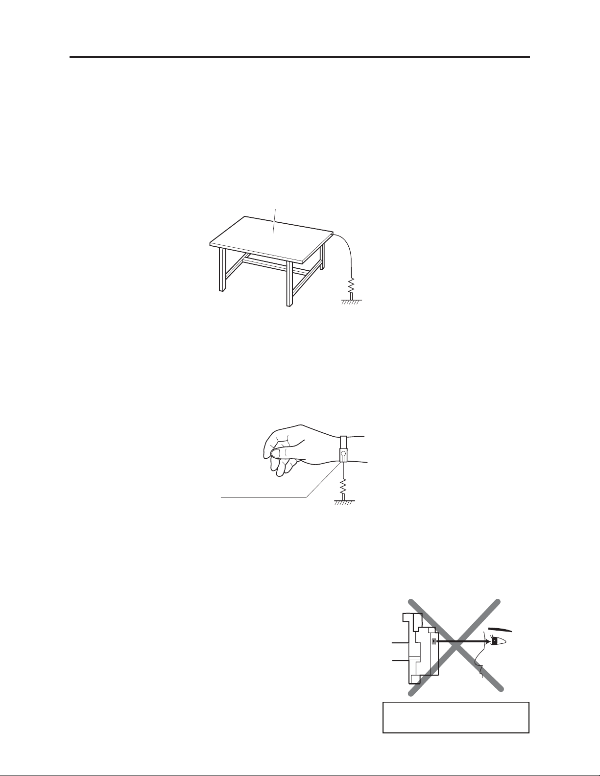
(1) Grounding work bench
Lay out an antistatic mat on work bench, and then use the ground plate to ground the work bench.
Antistatic mat
1M ohm
Ground
(2) Grounding human body
Use an antistatic wrist strap to discharge any static electricity charged on the body. Also, use a
tester for wrist strap to make sure that the wrist strap is working normally. Note, however, that
static electricity charged on clothes will not be discharged by wrist strap: Therefore do not allow
your clothes to touch the semiconductor components.
Antistatic wrist strap
1M ohm
1-3 Cautions When Handling DVD Drive
The optical pickup in DVD drive has a high precision structure: Be sure to observe the following
cautions.
1) Do not subject optical pickups to any severe vibrations or
impact during movement, installation or disassembly.
2) When performing repair work, do not perform disassembly
any further than that described in this manual.
3) Never turn the semi-variable resistors for adjustment in
optical pickup or DVD drive.
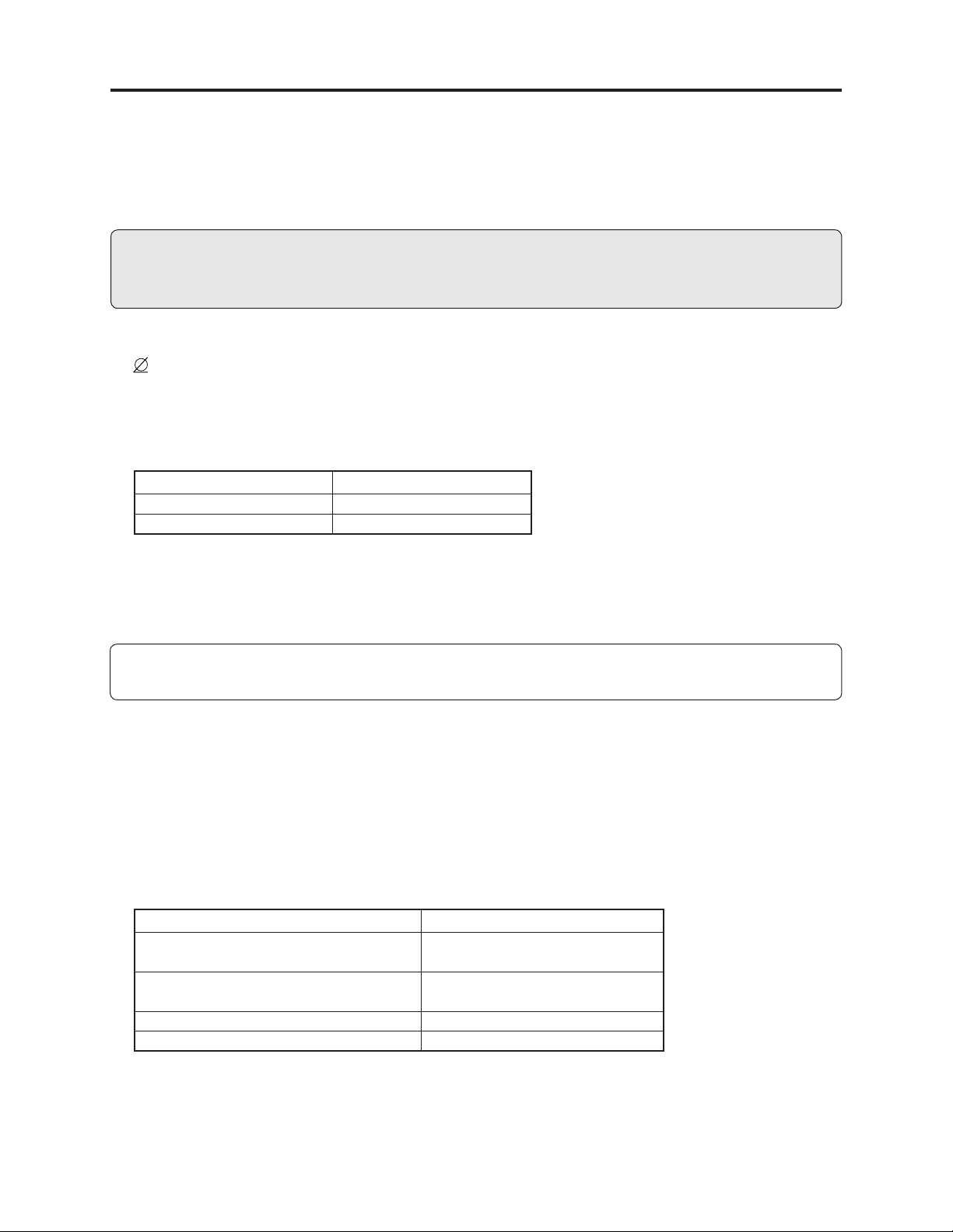
4) NEVER look into the objective lens in optical pickup or
directly view the laser light: You could lose your eyesight.
Do not directly look at laser light
from pickup.
1 - 2
Page 7
Safety Precaution for Repair > Lead-Free Solder
1-4 Lead-Free Solder
The printed circuit board that uses lead-free solder is adopted. To protect the global environment,
use the recommended lead-free solder also during servicing.
Read and observe the following before soldering:
Caution
ALWAYS wear protective goggles during soldering so that no solder smoke or scattered solder
enters the eye. Lead-free solder may scatter at high temperatures of 600°C.
(1) Identifi cation of circuit boards that use lead-free solder
Pb
“ ” is stamped or noted with pattern letter on circuit boards that use lead-free solder.
A30C5
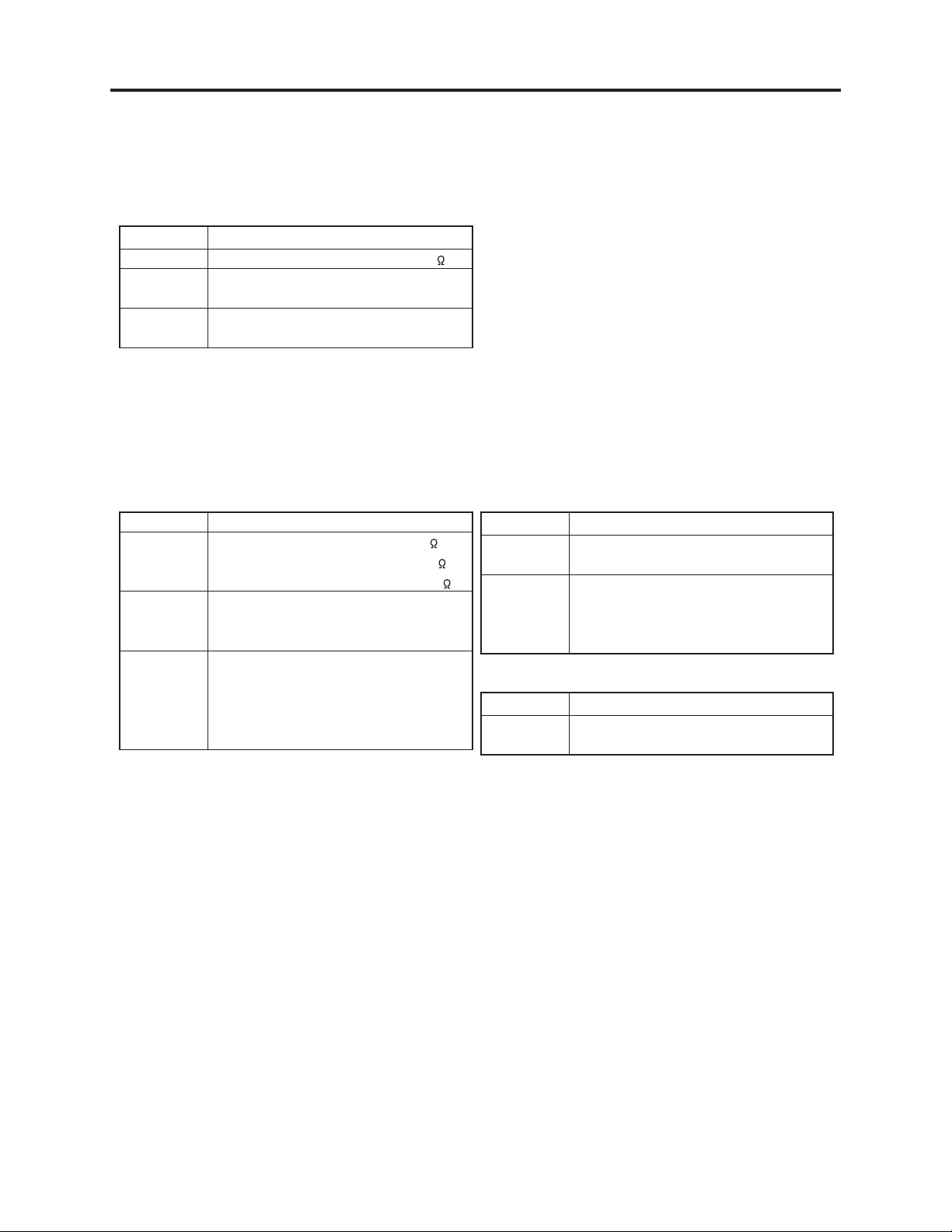
(2) Characteristics of lead-free solder
The components of lead-free solder used are as follows. The melting point of lead-free solder is
30-40°C higher than that of lead based solder:
Point to be soldered Composition of alloy (wt%)
For refl ow Solder paste: Sn-3Ag-0.5Cu
For dip Bar solder: Sn-0.6Cu
Melting temperature: Approx. 220°C
(3) Lead-free solder for servicing
Use the following lead-free solder for servicing:
Recommended lead-free solder and composition of alloy (wt%): Sn-3.0Ag-0.5Cu or equivalent
Information:
For composition of alloy, Sn is tin; Ag is silver; Cu is copper; Bi is bismuth; Pb is lead.
(4) Soldering iron for servicing
The temperature of soldering iron tip must be adjusted according to the points to be soldered: Use
an antistatic soldering iron with thermal control function.
When removing components, take care not to damage any surrounding component or pattern. When
attaching components, observe the heating time in the following table so that the components are
not destroyed by heat.
Tip temperatures for different soldering points:
oint to be soldered Tip temperature
Surface-mounted (chip) parts [other than
those shown below]
Surface-mounted (chip) parts [for DVD
cameras, cellular phones only]
Discrete parts 380 ± 30°C
Chassis, metal shield, etc. 420 ± 30°C
320 ± 30°C
[heating time: less than 5 seconds]
350 ± 10°C
[heating time: less than 3 seconds]
1 - 3
Page 8

Safety Precaution for Repair > Lead-Free Solder
(5) Cautions when using lead based solder
It is recommended that you use lead-free solder when servicing, but it is also possible to service
using lead based solder. However, if lead based solder is used for servicing, take care with the
following:
1) Before using lead based solder, remove the lead-free solder completely from the point to be
soldered.
2) For additional soldering for repair, set the soldering iron tip temperature for lead-free solder,
mix lead based solder and lead-free solder suffi ciently. Do not perform any repair using the
bare soldering iron tip without adding solder, since it will cause secondary failure due to lack of
strength.
1 - 4
Page 9
Safety Precaution for Repair > Notes When Using Service Manual
1-5 Notes When Using Service Manual
(1) Value units used in parts list
Certain symbols are indicated as shown below for value units of resistors, capacitors and coils in
parts list. When you read them, note the following regular indications:
Parts Indication in list Regular indication
Resistor KOHM ..........................................k
Capacitor UF ................................................. F
PF .................................................. pF
Coil UH ................................................H
MH ................................................ mH
(2) Values in schematic diagrams
The values, dielectric strength (power capacitance) and tolerances of the resistors (excluding
variable resistors) and capacitors are indicated in the schematic diagrams using abbreviations.
Certain symbols are indicated for value units: When you read them note the regular indications in
tables below:
[Resistors] [Capacitors]
Item Indication
Value No indication ................................
K.................................................... k
M ................................................... M
Tolerance No indication ................................ ±5%
(All tolerances other than ±5% are
indicated in schematic diagrams)
Power
capacitance
No indication ................................ 1/8W
(1/16 W for leadless resistors with no
indication)
All capacitances other than the above
are indicated in schematic diagrams.
Item Indication
Value No indication ................................ F
P .................................................... pF
Dielectric
strength
No indication ............................... 50V
(All dielectric strengths other than
50 V are indicated in schematic
diagrams)
[Coils]
Item Indication
Value .................................................... H
m ................................................... mH
(3) Identifying sides A/B in circuit board diagrams
1) Board with pattern on one side only and parts on both sides:
Side A: Shows discrete parts.
Side B: Shows leadless parts, viewed from the pattern side.
2) Board with patterns and parts on both sides:
Side A: Shows parts and patterns which can be seen when the case is opened.
Side B: Shows the parts and the pattern on the back of side A.
1 - 5
Page 10

Safety Precaution for Repair > Notes When Using Service Manual
(4) Indicating model names
The indication of models is defi ned as follows:
1) The common parts of model names are omitted.
Example: When indicating VM-D975LA and VM-D875LA:
VM-D975LA/D875LA, D975LA/D875LA
2) If there is no difference in models going to different destinations, the indication of destination is
omitted.
Example: When indicating DZ-MV350E(AU) and DZ-MV350E(SW): DZ-MV350E
(5) Differences in parts between schematic and circuit board diagrams
If parts differ between models, asterisks * are attached to circuit numbers.
See parts difference tables in diagrams for details.
1 - 6
Page 11
2
General Description
2-1 Overview
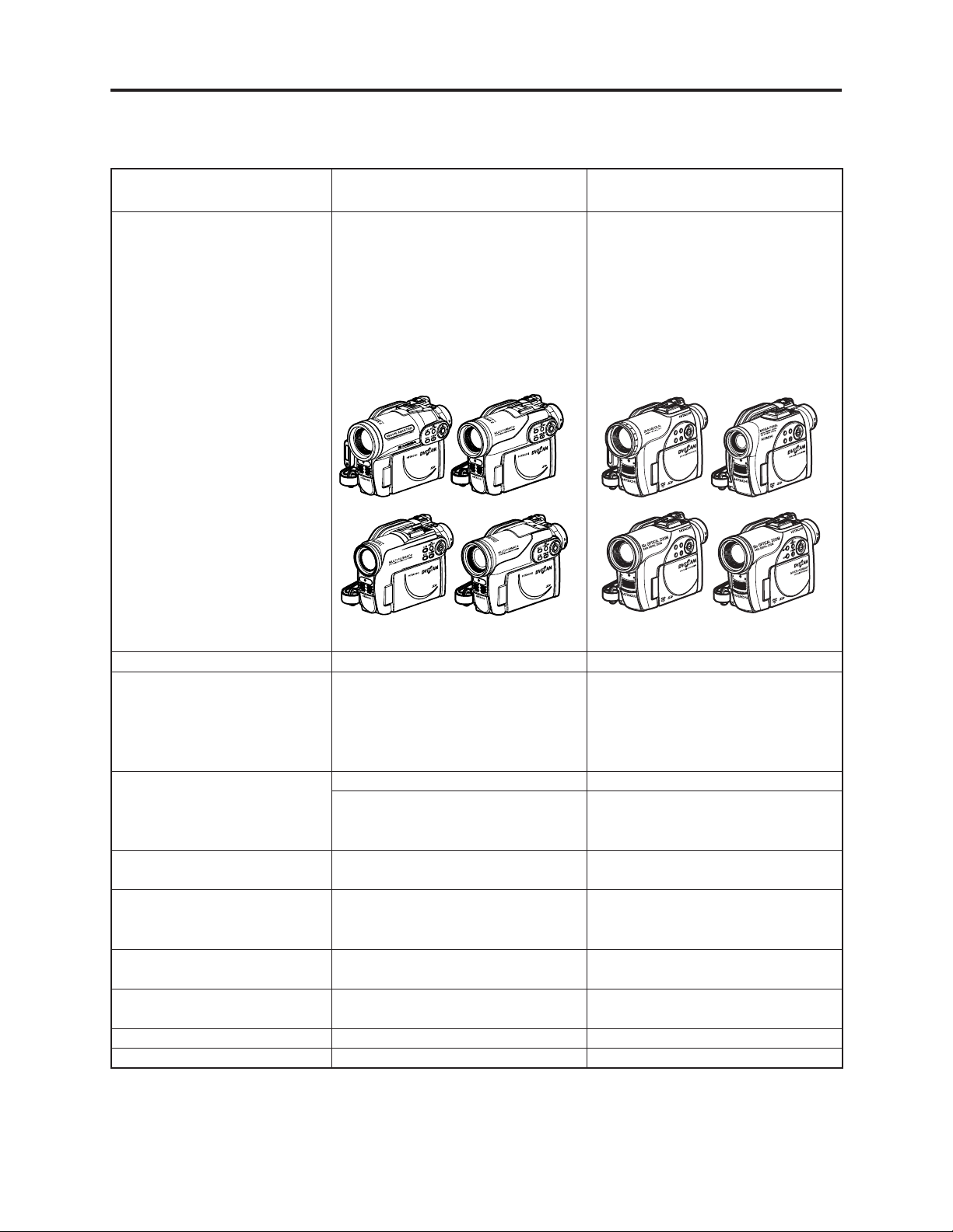
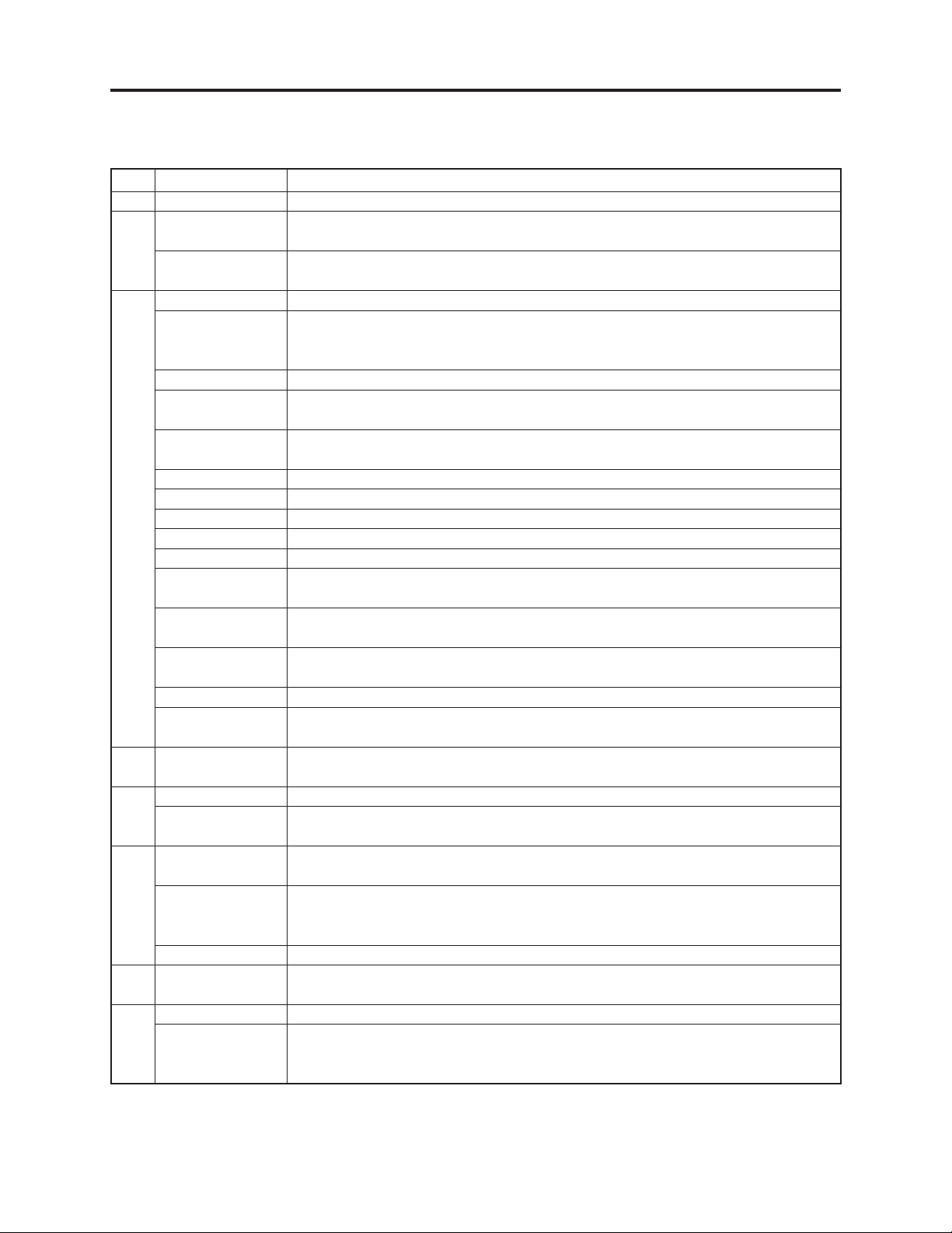
The DZ-GX3300E/GX3200E/GX3100E/BX37E/BX35E/MV4000E DVD video camera/recorders can
record on a +RW and play it back.
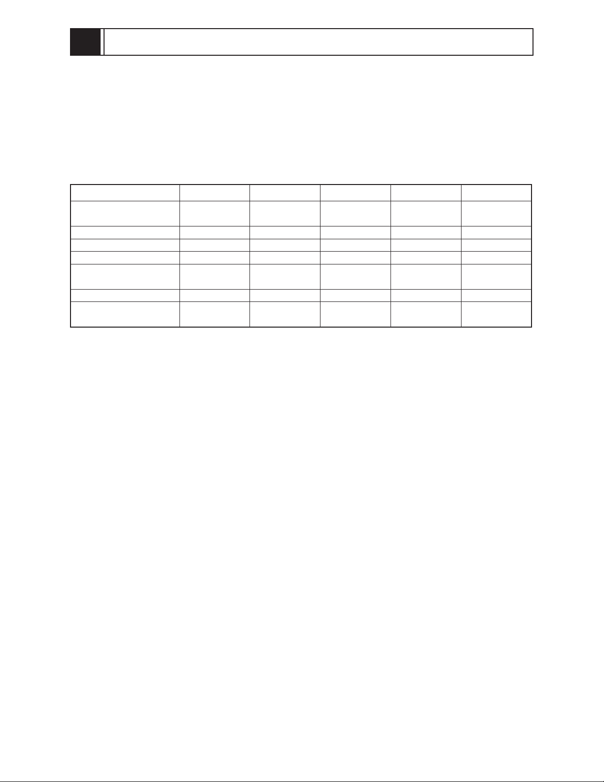
The following table shows the major differences among DZ-GX3300E/GX3200E/GX3100E/BX37E/
BX35E/MV4000E. (See “2-5 Difference in Rating Labels and Difference in Function” for the
diffreneces in line input function):
ł : Same as on left
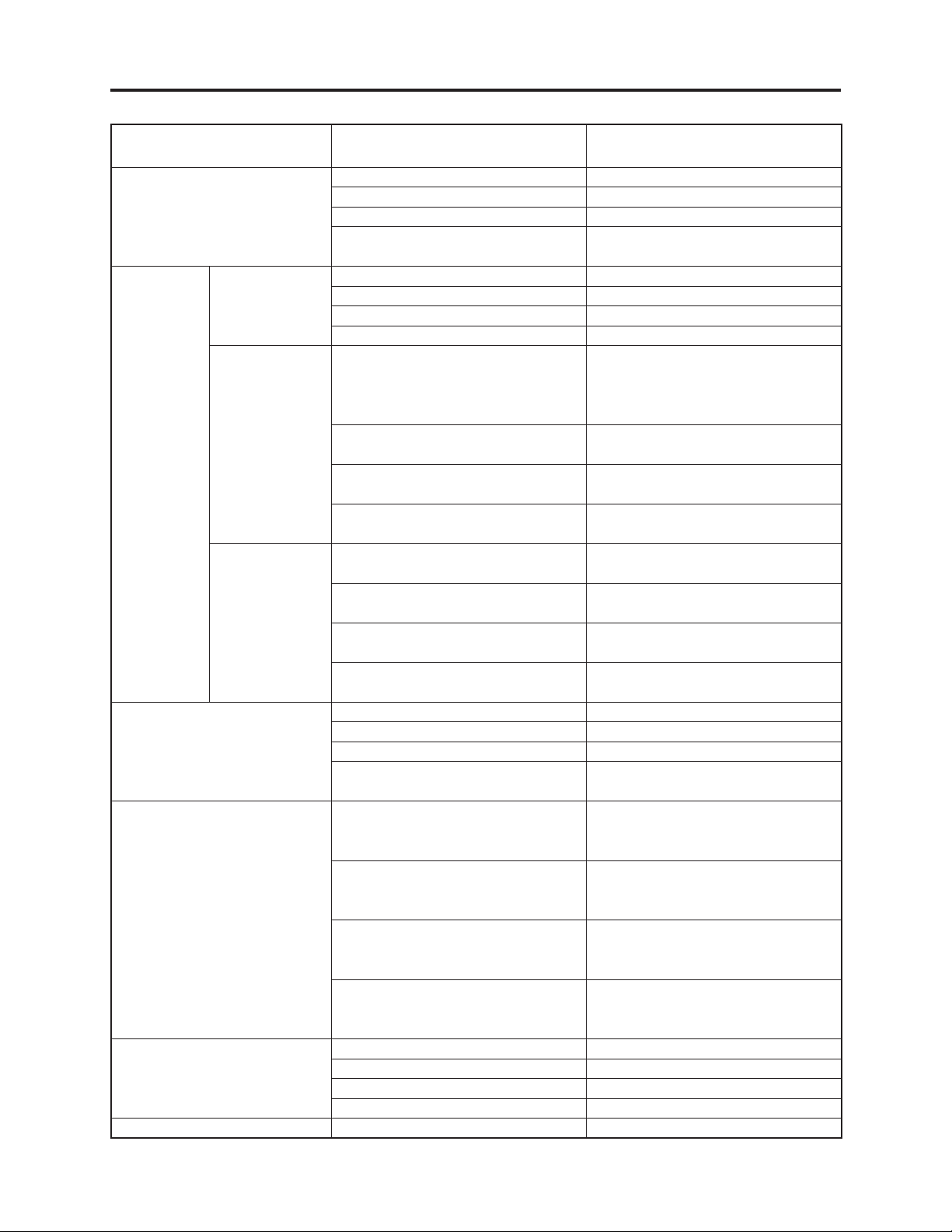
Specification/ Function DZ-GX3300E DZ-GX3200E DZ-GX3100E DZ-BX37E
CCD Image Sensor apprpx.
3,310,000 pixel
Optical Zoom x10 x10 x15 x25 x25
Flash Provided Not provided Not provided Not provided Not provided
Accessory shoe Provided Provided Provided Not provided Not provided
Power/control terminal
on accessory shoe
PC Connection Terminal Provided Provided Provided Provided Not provided
External Microphone
Jack
Provided Provided Not provided ----- -----
Provided Provided Provided Not provided Not provided
apprpx.
2,120,000 pixel
apprpx.
1,330,000 pixel
apprpx.
800,000 pixel
DZ-BX35E/MV4000E
apprpx.
800,000 pixel
2 - 1
Page 12
General Description > Overview
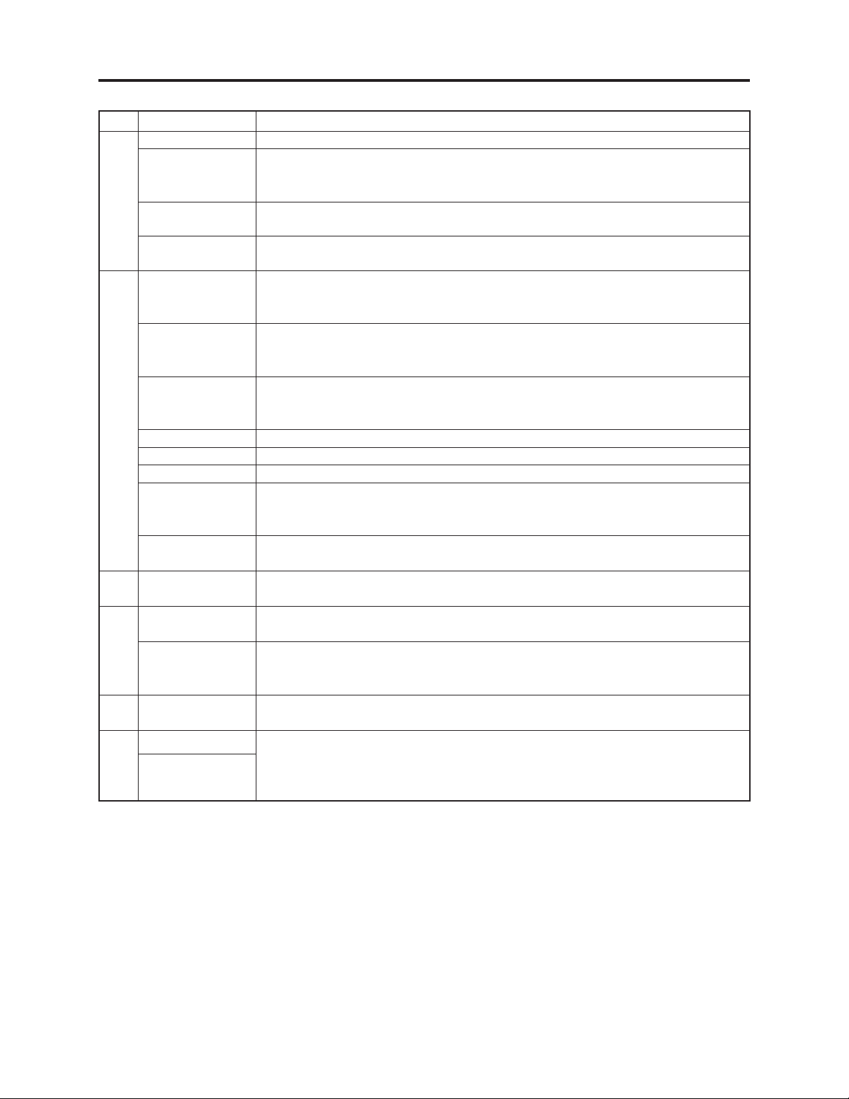
2-1-1 Servicing Method
Refer to the following table and perform the designated, appropriate servicing. Any changes that
occur in the service method will be published using service bulletin, etc.
Do not perform any servicing other than that described in this manual.
ł : Same as on left
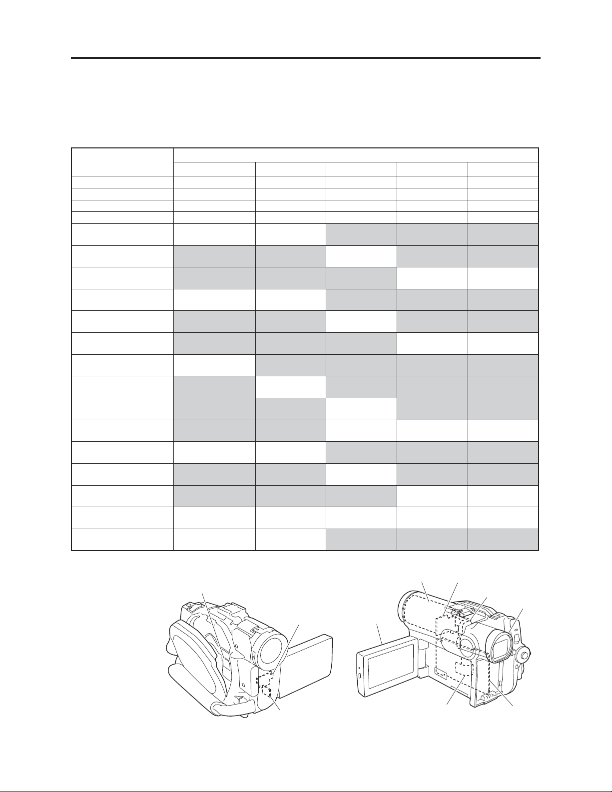
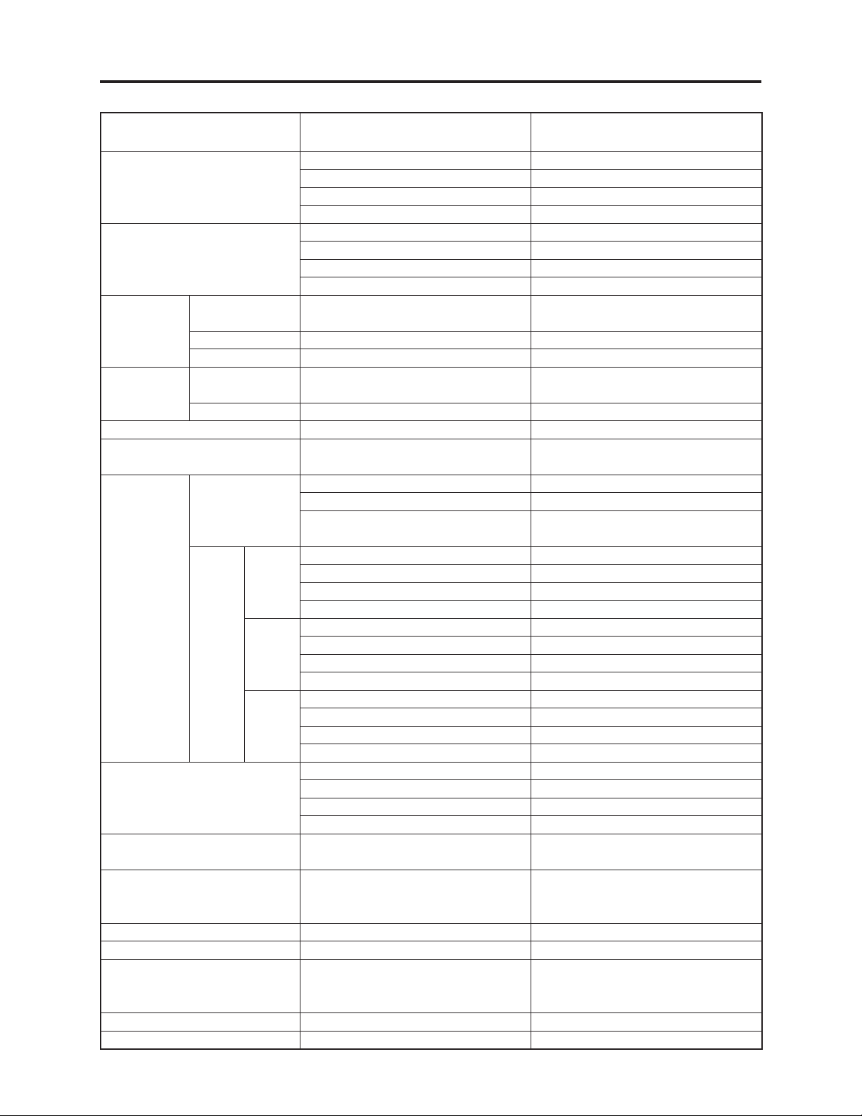
Parts Name Servicing Method
DZ-GX3300E DZ-GX3200E DZ-GX3100E DZ-BX37E
Disc Drive Unit Unit replacement łłłł
Lens Unit Unit replacement łłłł
EVF Unit Unit replacement łłłł
LCD Unit Unit replacement łłłł
AVJ-H Circuit Board
AVJ-M Circuit Board Not provided ł
AVJ-L Circuit Board Not provided łł
FRT-H Circuit Board
FRT-M Circuit Board Not provided ł
FRT-L Circuit Board Not provided łł
GSL-3M Circuit Board
GSL-2M Circuit Board Not provided
GSL-1M Circuit Board Not provided ł
GSL-L Circuit Board Not provided łł
LMF-H Circuit Board
LMF-M Circuit Board Not provided ł
LMF-L Circuit Board Not provided łł
MAN Circuit Board
SHE-H Circuit Board
Component
replacement
Component
replacement
Component
replacement
Component
replacement
Component
replacement
Component
replacement
ł Not provided łł
Component
replacement
ł Not provided łł
Component
replacement
Not provided łłł
Component
replacement
ł Not provided łł
łłłł
ł Not provided łł
Not provided łł
Component
replacement
Component
replacement
Not provided ł
Component
replacement
Not provided ł
Component
replacement
Not provided ł
Component
replacement
Not provided ł
Component
replacement
DZ-BX35E/MV4000E
ł
ł
ł
ł
(a) Disc drive unit
(b) Lens unit
(c) EVF unit
(d) LCD unit
(e) AVJ-H/M/L
circuit board
(f) FRT-H/M/L
circuit board
(g) GSL-3M/2M/1M/L
circuit board
(h) LMF-H/M/L
circuit board
(i) MAN circuit board
(j) SHE-H circuit board
(a)
(f)
(e)
Fig. 2-1-1 Name of the circuit board/unit
2 - 2
(d)
(b)
(h)
(g)
(j)
(c)
(i)
Page 13
General Description > Features / Specifi cations
2-2 Features
Compatibility with +RW:
In addition to DVD-RAM, DVD-RW, DVD-R and SD memory card, +RW can also be recorded and
played back.
SLEEP/RESTART button:
Pressing the SLEEP button in the recording pause status will shift the DVD video camera/
recorder to the SLEEP mode, in which the recording pause status is held using a minimum
electric power.
FINALIZE button:
Simply pressing this button will fi nalize the recorded DVD-RW, DVD-R and +RW.
High-quality recording:
The DZ-GX3300E/GX3200E/GX3100E incorporates a mega-pixel CCD image sensor and a highperformance zoom lens.
Recording in XTRA mode, which is the best movie quality, is possible on all compatible discs.
16:9 wide LCD monitor:
A 16:9 wide lCD monitor that corresponds to the wide-screen mode is mounted.
Images in viewfi nder are also displayed in wide-screen mode.
Capturing still:
During movie playback, a desired scene can be recorded on SD memory card as a still.
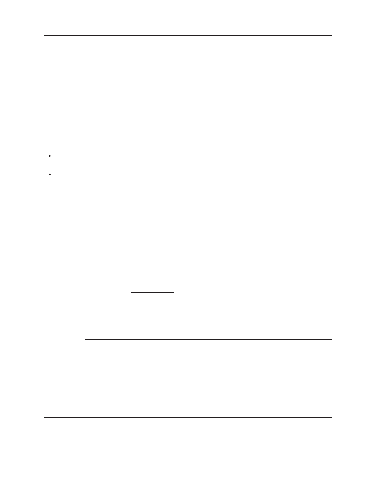
2-3 Specifi cations
Item Specifi cations
CCD Image Sensor DZ-GX3300E 1/3-inch interlaced
DZ-GX3200E 1/3.6-inch interlaced
DZ-GX3100E 1/5-inch interlaced
DZ-BX37/35E 1/6-inch interlaced
MV4000E
Total number of
pixels
Number of
effective pixels
DZ-GX3300E Approx. 3,310,000
DZ-GX3200E Approx. 2,120,000
DZ-GX3100E Approx. 1,330,000
DZ-BX37/35E Approx. 800,000
DZ-MV4000E
DZ-GX3300E Movie: Approx. 2,140,000
Movie in wide mode: Approx. 1,640,000
Still: Approx. 3,050,000
DZ-GX3200E Movie: Approx. 1,230,000
Still: Approx. 1,920,000
DZ-GX3100E Movie: Approx. 690,000
Movie in wide mode: 810,000
Still: Approx. 1,100,000
DZ-BX37/35E Movie: approx. 410,000
DZ-MV4000E
Still: approx. 410,000
2 - 3
Page 14
General Description > Specifi cations
Item Specifi cations
Lens DZ-GX3300E F1.8 – 3.0, f=6.1 – 61 mm
DZ-GX3200E F1.8 – 2.2, f=4.5 – 45 mm
DZ-GX3100E F1.2 – 2.8, f=3.0 – 45 mm
DZ-BX37/35E F1.8 – 3.2, f=2.2 – 55 mm
DZ-MV4000E
Filter diameter/
Thread pitch
Focus Auto/Manual
Zoom DZ-GX3300E Optical 10×, 40× – 500× with digital zoom added (40× for
Required minimum illumination 0.3 lx in Low Light mode
Viewfi nder 0.2-inch colour (equivalent to approx. 200,000 pixels)
LCD monitor 2.7-inch colour TFT (approx. 120,000 pixels)
Image stabiliser Electronic type
Shutter speed 1/4 – 1/4000 seconds (movie)
Self-timer recording Still recording only
External microphone jack
(Not equipped with DZ-BX37E/BX35E/MV4000E)
Recording mode Movie with sound (DVD-RAM/DVD-RW/DVD-R/+RW)
Maximum
recordable
Maximum recordable time (per
side)
time (per side)
Maximum
number of
DVD-RAM
(per side)
recordable
stills
SD memory
card
(when using 32
MB card)
DZ-GX3300E 37 mm / 0.75 mm
DZ-GX3200E 34 mm / 0.5 mm
DZ-GX3100E 30.5 mm / 0.5 mm
DZ-BX37/35E 34 mm / 0.5 mm
DZ-MV4000E
DZ-GX3200E
still)
DZ-GX3100E Optical 15×, 60× – 800× with digital zoom added (60× for
still)
DZ-BX37/35E Optical 25×, 100× – 1,200× with digital zoom added (100×
DZ-MV4000E
for still)
ø3.5 mm stereo mini-jack
(a plug-in power type microphone cannot be used)
Still (DVD-RAM/SD memory card)
XTRA mode: Approx. 18 minutes
FINE mode: Approx. 30 minutes
STD Mode: Approx. 60 minutes
DZ-GX3300E Camera recording: Approx. 650
External input recordeing: Approx. 999
DZ-GX3200E Camera/External input recordeing: Approx. 999
(*1)
(*1)(*3)
(*1)(*3)
DZ-GX3100E
DZ-BX37/35E Camera recordeing: Approx. 999
(*1)
DZ-MV4000E
DZ-GX3300E Camera recording: Approx. 18 (in FINE mode)
External input recordeing: Approx. 180 (in FINE mode)
DZ-GX3200E Camera recording: Approx. 29 (in FINE mode)
External input recordeing: Approx. 180 (in FINE mode)
DZ-GX3100E Camera recording: Approx. 45 (in FINE mode)
External input recordeing: Approx. 180 (in FINE mode)
DZ-BX37/35E Camera recording: Approx. 180 (in FINE mode)
(*2)
(*2)(*3)
(*2)
(*2)(*3)
(*2)
(*2)(*3)
(*2)
DZ-MV4000E
2 - 4
Page 15
General Description > Specifi cations
Item Specifi cations
Recording
format
Audio playback format MPEG Audio layer 2, linear PCM, Dolby Digital
Recording medium 8 cm DVD-RAM disc (conforming to DVD-RAM Ver. 2.1)
Jacks Video/audio output ×1,
Battery system Lithium-ion
Power consumption
(when recording with LCD
monitor off )
Dimensions
(W × H × D, excluding
projections)
Operating temperature (humidity) 0 – 40ºC (less than 80%).
Storage temperature -20 – 60ºC
Weight
(without battery and disc)
DVD-RAM/DVD-RW (VR-mode) Movie: Conforming to DVD video recording (DVD-VR)
format
Sound: Dolby Digital
Still (DVD-RAM only):
Simultaneous recording, conforming to DVD video
recording (DVDVR) standard (720 × 576 pixels) and JPEG
(DZ-GX3300E: 2,016×1,512 pixels, DZ-GX3200E: 1,600 ×
1,200 pixels, DZ-GX3100E: 1,280 × 960 pixels, DZ-BX37E/
BX35E/MV4000E: 640 × 480 pixel)
[JPEG of external input
(*3)
: 640 × 480 pixels]
DVD-RW (VF-mode)/DVD-R Movie: Conforming to DVD video format
Sound: Dolby Digital
+RW Movie: DVD+RW video format
Sound: Dolby Digital
Card Still: Conforming to JPEG (DZ-GX3300E: 2,016×1,512
pixels, DZ-GX3200E: 1,600 × 1,200 pixels, DZ-GX3100E:
1,280 × 960 pixels, DZ-BX37E/BX35E/MV4000E: 640 × 480
pixels, standard)
[External input
(*3)
: 640 × 480 pixels]
8 cm DVD-RW (conforming to DVD-RW Ver. 1.1, 2x speed
[2x/1x])
8 cm DVD-R disc (conforming to DVD-R for General Ver. 2.0)
8 cm +RW (conforming to +RW Ver. 1.2)
SD memory card
External microphone input ×1 (not equipped with DZ-
BX37E/BX35E/MV4000E),
PC connection terminal (connected to PC USB port) ×1 (not
equipped with DZ-BX35E/MV4000E)
DZ-GX3300E Approx. 5.1 W (DVD-RAM used, FINE mode)
DZ-GX3200E Approx. 4.4 W (DVD-RAM used, FINE mode)
DZ-GX3100E Approx. 3.8 W (DVD-RAM used, FINE mode)
DZ-BX37/35E Approx. 3.2 W (DVD-RAM used, FINE mode)
DZ-MV4000E
DZ-GX3300E Approx. 48 × 91 × 132 mm
DZ-GX3200E Approx. 48 × 89 × 132 mm
DZ-GX3100E Approx. 48 × 86 × 121 mm
DZ-BX37/35E Approx. 48 × 89 × 131 mm
DZ-MV4000E
0 – 30ºC when connected to PC
DZ-GX3300E Approx. 470 g
DZ-GX3200E Approx. 450 g
DZ-GX3100E Approx. 420 g
DZ-BX37/35E
DZ-MV4000E
2 - 5
Page 16
General Description > Specifi cations
Item Specifi cations
Total weight when recording DZ-GX3300E Approx. 545 g
DZ-GX3200E Approx. 525 g
DZ-GX3100E Approx. 475 g
DZ-BX37/35E
DZ-MV4000E
Provided accessories AC adapter/charger (DZ-ACS3)
Battery [DZ-GX3300E/GX3200E: DZ-BP14S, DZ-GX3100E/
BX37E/BX35E/MV4000E: DZ-BP07PW]
AV/S output cable,
Infrared remote control [not provided with DZ-BX37E/
BX35E/MV4000E]
Lithium battery for remote control [not provided with DZ-
BX37E/BX35E/MV4000E]
Lens cap
Lens cap string
Shoulder strap
Mains lead
DC power cord
Software CD-ROM [
PC connection cable [
Single-sided 8 cm DVD-R disc [not provided with DZ-
BX37E/BX35E/MV4000E]
Disc cleaning cloth
not provided with DZ-BX37E/BX35E/MV4000E
not provided with DZ-BX35E/MV4000E
]
]
*1: The number may decrease when videos are recorded on DVD-RAM, depending on the amount of
recorded data.
*2: May vary depending on the image quality.
*3: The line input function is provided in the following models:
DZ-GX3300E(AU)/GX3300E(SW)/GX3300E(SWC)/GX3300E(SWH)
DZ-GX3200E(AU)/GX3200E(SW)/GX3200E(SWC)/GX3200E(SWH)
DZ-GX3100E(AU)/GX3100E(SW)/GX3100E(SWC)/GX3100E(SWH)
The symbols in parentheses ( ) in the above model names show the destinations and are displayed
only on packing box.
Refer to 2-5 Differences in Rating Labels and Difference in Function when checking the body of DVD
video camera/recorder, to judge whether or not it is equipped with the line input function (destination).
Specifi cations are subject to change without notice for the purpose of improvement.
Specifi cations of AC Adapter/Charger [DZ-ACS3(E) / ACS3(SW)]
Power supply 110 - 240 V AC,
50/60 Hz
Input capacity 19W
DC output (max.) 1.2 A
Charge output 8.4 V, 0.65A
Weight 100 g
External dimensions
(W × H × D)
Ambient temperature for
operation
Allowable relative
humidity
61 × 32 × 91 mm
0 - 40°C
20 - 80%
2 - 6
Page 17
General Description > Major Differences from Previous Models
2-4 Major Differences from Previous Models
Item DZ-GX3300E/ GX3200E/ GX3100E/
Dimensions (W × H × D) and
shape
BX37E/ BX35E/ MV4000E
DZ-GX3300E:
Approx. 48 × 91 × 132 mm
DZ-GX3200E:
Approx. 48 × 89 × 132 mm
DZ-GX3100E:
Approx. 48 × 86 × 121 mm
DZ-BX37E/BX35E/MV4000E:
Approx. 48 × 89 × 131 mm
DZ-GX20E/ MV780E/ MV750E/
DZ-GX20E:
Approx. 51 × 90 × 137 mm
DZ-MV780E:
Approx. 51 × 86 × 123 mm
DZ-MV750E/MV730ME:
Approx. 51 × 89 × 133 mm
ł
: Same as on left
MV730ME
$:'8%
$:'8%
Disc holder Disused
Recording media 8cm DVD-RAM
8cm DVD-RW
8cm DVD-R
8cm +RW
$:'8%
DZ-BX37E/BX35E/MV4000E
8cm DVD-RAM
8cm DVD-R
SD memory card
8cm DVD-RW (DZ-MV730ME only)
$:'8%
$:-6% $:-6-%
ł
SD memory card
Internal fl ash DZ-GX3300E: Provided DZ-GX20E: Provided
DZ-GX3200E/ GX3100E/ BX37E/
BX35E/MV4000E:
DZ-MV780E/ MV750E/ MV730ME:
Not provided
Not provided
Assist light funtion Provided
(When Low Light mode is selected)
16:9 squeeze record mode Provided
[Except for DVD-RW(VF mode)/DVDR/+RW using, STD mode]
Viewfi nder 0.2-inch colour (equivalent to approx.
200,000 pixels, with 16:9 mode)
LCD monitor 16:9, 2.7-inch colour TFT
(approx. 120,000 pixels)
Provided
[Except for DVD-RW(VF mode)/
DVD-R using, STD mode]
0.2-inch colour (equivalent to approx.
200,000 pixels)
2.5-inch colour TFT
(approx. 120,000 pixels)
ł
Sleep/Restart button Provided Not provided
Finalize button Provided Not provided
$:-6%
2 - 7
Page 18
General Description > Major Differences from Previous Models
Item DZ-GX3300E/ GX3200E/ GX3100E/
BX37E/ BX35E/ MV4000E
CCD image sensor DZ-GX3300E: 1/3-inch interlaced -----
DZ-GX3200E: 1/3.6-inch interlaced DZ-GX20E: ł
DZ-GX3100E: 1/5-inch interlaced DZ-MV780E: 1/4.5-inch interlaced
DZ-BX37E/BX35E/MV4000E: 1/6-inch
interlaced
Total number of
pixels
Number of pixels
for Movie
Number of pixels
for still
Lens
Zoom DZ-GX3300E:
Filter diameter / Thread pitch DZ-GX3300E: 37 mm / 0.75 mm
Required minimum illumination
DZ-GX3300E: Approx. 3,310,000
DZ-GX3200E: Approx. 2,120,000 DZ-GX20E: ł
DZ-GX3100E: Approx. 1,330,000 DZ-MV780E: ł
DZ-BX37/35E/MV4000E: ~ 800,000 DZ-MV750E/MV730ME: ł
DZ-GX3300E: Approx. 2,140,000
pixels
(in wide mode: Approx. 1,640,000
pixels)
DZ-GX3200E: Approx. 1,230,000
pixels
DZ-GX3100E: Approx. 690,000 pixels DZ-MV780E: ł
DZ-BX37E/BX35E/MV4000E: Approx.
410,000 pixels
DZ-GX3300E: Approx. 3,050,000
pixels
DZ-GX3200E: Approx. 1,920,000
pixels
DZ-GX3100E: Approx. 1,100,000
pixels
DZ-BX37E/BX35E/MV4000E: Approx.
410,000 pixels
DZ-GX3300E: F1.8 - 3.0, f = 6.1 - 61 mm
DZ-GX3200E: F1.8 - 2.2, f = 4.5 - 45 mm
DZ-GX3100E: F1.2 - 2.8, f = 3.0 - 45 mm
DZ-BX35E/BX37E/MV4000E:
F1.8 - 3.2, f = 2.2 - 55 mm
Optical 10x, 40x - 500x with digital
zoom added (40x for still)
DZ-GX3200E:
Optical 10x, 40x - 500x with digital
zoom added (40x for still)
DZ-GX3100E:
Optical 15x, 60x - 800x with digital
zoom added (60x for still)
DZ-BX37E/BX35E/MV4000E:
Optical 25x, 100x - 1,200x with
digital zoom added (100x for still)
DZ-GX3200E: 34 mm / 0.5 mm DZ-GX20E: ł
DZ-GX3100E: 30.5 mm / 0.5 mm DZ-MV780E: ł
DZ-BX37/35E/MV4000E: 34 / 0.5 mm DZ-MV750E/MV730ME: ł
0.3 lx (Low light mode)
DZ-GX20E/ MV780E/ MV750E/
MV730ME
DZ-MV750E/MV730ME: ł
-----
-----
DZ-GX20E: ł
DZ-MV750E/MV730ME: ł
-----
DZ-GX20E: ł
DZ-MV780E: ł
DZ-MV750E/MV730ME: ł
----DZ-GX20E: ł
DZ-MV780E: F1.8 - 2.3, f = 3.2 - 32 mm
DZ-MV750E/MV730ME:
F1.6 - 2.3, f = 2.78 - 43.3 mm
-----
DZ-GX20E:
Optical 10x, 40x - 240x with digital
zoom added (40x for still)
DZ-MV780E:
Optical 10x, 40x - 240x with digital
zoom added (40x for still)
DZ-MV750E/MV730ME:
Optical 16x, 40x - 240x with digital
zoom added (40x for still)
-----
ł
2 - 8
Page 19
General Description > Major Differences from Previous Models
Item DZ-GX3300E/ GX3200E/ GX3100E/
DZ-GX20E/ MV780E/ MV750E/
BX37E/ BX35E/ MV4000E
Power consumption
(DVD-RAM used, FINE mode)
Weight DZ-GX3300E: Approx. 470g
Maximum
time of
recordable
video (per side)
Number of
pixels for video
(MPEG2)
Audio recording format Dolby Digital
Audio playback format Dolby Digital, MPEG Audio layer 2,
Maximum
number of
recordable
Stills
Number of pixels for JPEG Still
during camera recording
Number of pixels for JPEG Still
during line-input
Number of pixels for MPEG
Still during camera/line-input
recording
PHOTO button Provided (with focus lock function)
Quick Menu button Not provided Provided
EIS function Movie mode only
Disc protect Software disc-protect
EVF brightness setting function Provided
XTRA Approx. 18 min/Variable: Approx. 3 -
FINE Approx. 30 min/Fix: Approx. 6 Mbp
STD Approx. 60 min/Fix: Approx. 3 Mbps
XTRA/FINE 720 × 576 pixels 704 × 576 pixels
STD 352 × 576 pixels
DVD-RAM
(FINE)
SD
Memory
cord
(32MB)
(*1)
FINE DZ-GX3300E: Approx. 18
NORM DZ-GX3300E: Approx. 24
ECO DZ-GX3300E: Approx. 37
recording
DZ-GX3300E: Approx. 5.1W
DZ-GX3200E: Approx. 4.4W DZ-GX20E: ł
DZ-GX3100E: Approx. 3.8W DZ-MV780E: ł
DZ-BX37/35E/MV4000E: App. 3.2W DZ-MV750E/MV730ME: ł
DZ-GX3200E: Approx. 450g DZ-GX20E: Approx. 480g
DZ-GX3100E: Approx. 420g DZ-MV780E: ł
DZ-BX37/35E/MV4000E: App. 420g
10 Mbps
Linear PCM (LPCM)
DZ-GX3300E: Approx. 650 ----DZ-GX3200E: Approx. 999 DZ-GX20E: Approx. 750
DZ-GX3100E/BX37E/BX35E/MV4000E:
Approx. 999
DZ-GX3200E: Approx. 29 DZ-GX20E: ł
DZ-GX3100E: Approx. 45 DZ-MV780E: Approx. 58
DZ-BX37/35E/MV4000E: App. 180 DZ-MV750E/MV730ME: Approx. 232
DZ-GX3200E: Approx. 38 DZ-GX20E: ł
DZ-GX3100E: Approx. 60 DZ-MV780E: Approx. 76
DZ-BX37/35E/MV4000E: App. 240 DZ-MV750E/MV730ME: Approx. 464
DZ-GX3200E: Approx. 58 DZ-GX20E: ł
DZ-GX3100E: Approx. 90 DZ-MV780E: Approx. 116
DZ-BX37/35E/MV4000E: App. 370 DZ-MV750E/MV730ME: Approx. 928
DZ-GX3300E: 2016×1512 pixels
DZ-GX3200E: 1600×1200 pixels DZ-GX20E: ł
DZ-GX3100E: 1280×960 pixels DZ-MV780E: ł
DZ-BX37/35E/MV4000E: 640×480 DZ-MV750E/MV730ME: ł
640 × 480 pixels
720 × 480 pixels 704 × 480 pixels
(*1)
DZ-MV750E/MV730ME: Approx. 450g
DZ-MV780E/MV750E/MV730ME:
DZ-GX20E/MV780E: Movie mode only
DZ-MV750E/MV730ME: Movie & Still
mode
MV730ME
-----
ł
ł
ł
ł
ł
ł
ł
-----
-----
-----
-----
ł
ł
ł
ł
2 - 9
Page 20

General Description > Major Differences from Previous Models
Item DZ-GX3300E/ GX3200E/ GX3100E/
DZ-GX20E/ MV780E/ MV750E/
BX37E/ BX35E/ MV4000E
EVF display on/off funtion Provided
Accessory Shoe DZ-GX3300E/GX3200E: Provided
(with Power/Control terminal)
DZ-GX3100E: Provided DZ-MV750E/MV730ME: Provided
DZ-BX37/35E/MV4000E: Not provided
PC connection terminal
[USB standard]
DZ-GX3300E/GX3200E/GX3100E/
BX37E: Type mini-B [USB 2.0]
DZ-BX35E/MV4000E: Not provided DZ-MV730ME: ł
AC adapter/charger DZ-ACS3(E)/ACS3(SW) DZ-ACS2(E)
Battery pack DZ-GX3300E/GX3200E provided:
DZ-BP14S (7.2V/1360mA)
DZ-GX3100E/BX37E/BX35E/
MV4000E provided:
DZ-DP07PW
(*2)
(7.2V/680mA)
Optional:
DZ-BP14SW (7.2V/1360mA)
(*2)
(7.2V/680mA)
Infrared remote control
DZ-BP7SW
DZ-RM4W (Battery: CR2032 × 1)
[Not provided with DZ-BX37/35EMV4000E]
AV input(*1)/output cable Pin 8 type (With Composite video/
Audio-L/Audio-R)
Provided software
(Except for DZ-BX37E/ BX35E/
MV4000E/ MV730ME)
ʄFor Windows
ImageMixer 3
ʄFor Macintosh
(*3)
(*4)
Pixe VRF Browser EX,
ImageMixer VCD/DVD2
Provided disc cleaning cloth Provided
DZ-GX20E/MV780E: ł
DZ-GX20E/MV780E/MV750E:
DZ-GX20E provided:
DZ-MV780E/MV750E/MV730ME
provided:
DZ-BP7S
(*2)
Optional:
[Not provided DZ-MV730ME]
Pin 8 type (With S-video/Composite
video/Audio-L/Audio-R)
ʄFor Windows
DVD-MovieAlbum,
DVDfunSTUDIO,
UDF driver
MV730ME
ł
ł
ł
(7.2V/680mA)
ł
ł
(*5)
ł
*1: The line input function is provided in the following models:
DZ-GX3300E(AU)/GX3300E(SW)/GX3300E(SWC)/GX3300E(SWH)
DZ-GX3200E(AU)/GX3200E(SW)/GX3200E(SWC)/GX3200E(SWH)
DZ-GX3100E(AU)/GX3100E(SW)/GX3100E(SWC)/GX3100E(SWH)
The symbols in parentheses ( ) in the above model names show the destinations and are displayed
only on packing box.
Refer to "2-5 Differences in Rating Labels and Difference in Function" when checking the body of DVD
video camera/recorder, to judge whether or not it is equipped with the line input function (destination).
*2: Unavailable on DZ-GX3300E/GX3200E/GX20E.
*3: For Windows 2000 Professional SP3 or higher/XP Home Edition/XP Professional
*4: Mac OS X (10.2.8/10.3.4-10.3.9/10.4.1-10.4.3)
*5: For Windows Me/2000 Professional/XP Home Edition/XP Professional
2 - 10
Page 21
General Description > Major Differences from Previous Models
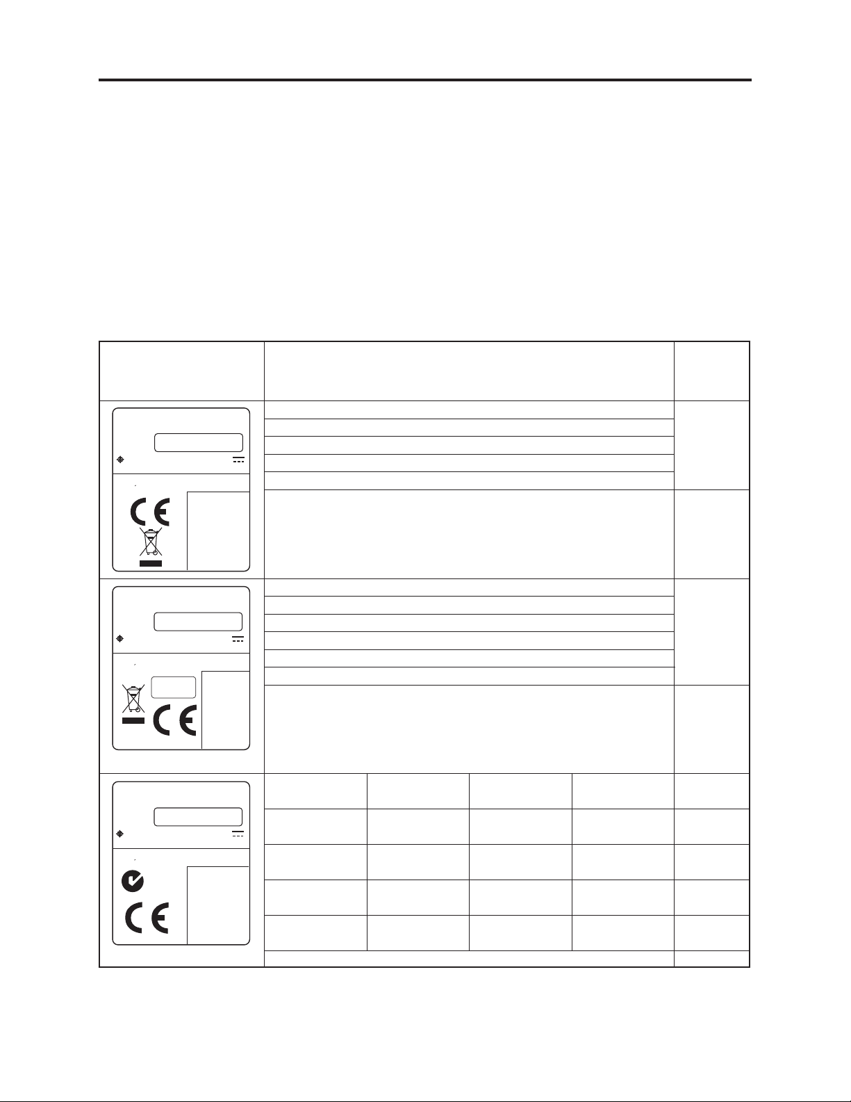
2-5 Differences in Rating Labels and Difference in Function
The suffi xes of model names - (AU), (SW), (UK), etc. - show the destinations where the models will
be shipped.
Even the same models may or may not have the AV input (line input) function depending on the
destination: When servicing the DVD camera/recorder models, be sure to check the rating label to
identify the destination.
Information:
Destinations (AU), (SW), (UK), etc. are shown only on the packing boxes.
There is no direct indication of destination (AU), (SW), (UK), etc. in rating label: Determine the
destination from the mark in label.
AV (Line)
Label Model
()4!#()
$6$6)$%/#!-%2!2%#/2$%2
-/$%,./
-/$%,/
(ITACHI,TD
-!$%).*!0!.&!"2)#!$/%.*!0/.
3%2)!,./
.gDESERIE
66
DZ-GX3300E
DZ-GX3200E
DZ-GX3100E
DZ-BX37E
DZ-BX35E
input
function
Not
provided
()4!#()
$6$6)$%/#!-%2!2%#/2$%2
-/$%,./
-/$%,/
(ITACHI,TD
-!$%).*!0!.&!"2)#!$/%.*!0/.
3%2)!,./
.gDESERIE
!PPROVED
()4!#()
$6$6)$%/#!-%2!2%#/2$%2
-/$%,./
-/$%,/
(ITACHI,TD
-!$%).*!0!.&!"2)#!$/%.*!0/.
3%2)!,./
.gDESERIE
66
"%!"
66
.
DZ-GX3300E(UK)
DZ-GX3200E(UK)
DZ-GX3100E(UK)
DZ-BX37E(UK)
DZ-BX35E(UK)
DZ-MV4000E(UK)
DZGX3300E(AU)
DZGX3200E(AU)
DZGX3100E(AU)
DZ-BX37E(AU) DZ-BX37E(SW) DZ-
DZGX3300E(SW)
DZGX3200E(SW)
DZGX3100E(SW)
DZGX3300E(SWC)
DZGX3200E(SWC)
DZGX3100E(SWC)
BX37E(SWC)
DZGX3300E(SWH)
DZGX3200E(SWH)
DZGX3100E(SWH)
DZBX37E(SWH)
DZ-BX35E(AU) DZ-BX35E(SW) DZ-
BX35E(SWH)
Not
provided
Provided
Provided
Provided
Not
provided
Not
provided
2 - 11
Page 22

General Description > Compatibility of Recorded Discs
2-6 Compatibility of Recorded DVD and Corresponding
Recording Media
2-6-1 Compatibility of Recorded Discs
(1) DVD-RAM
1) DVD-RAM recorded or edited on DZ-MV4000E/GX3300E/GX3200E/GX3100E/BX37E/BX35E:
The DVD-RAM can be recorded, edited and played
recorders.
2) DVD-RAM recorded or edited on other Hitachi DVD video camera/recorders:
The DVD-RAM can be recorded, edited and played
GX3100E/BX37E/BX35E.
However, scene memos recorded on the Disc Navigation function of DZ-MV100E cannot be played
or edited on another model.
*1: If disc-protect is set, it must be released in order to record or edit on the disc. However, since the
DZ-MV100E and DZ-MV200E series models use a different disc-protect method, disc-protect
that was set on other models cannot be released on them.
(*1)
on other Hitachi DVD video camera/
(*1)
on DZ-MV4000E/GX3300E/GX3200E/
(2) DVD-R
1) DVD-R recorded edited on DZ-MV4000E/GX3300E/GX3200E/GX3100E/BX37E/BX35E:
The DVD-R can be played back on other Hitachi DVD video camera/recorders
(*2)
without being
fi nalized. However, be sure not to record or fi nalize a DVD-R using other Hitachi DVD video
camera/recorders: Doing so will make the DVD-R unusable.
Also, do not insert a DVD-R not fi nalized into a DVD recorder, etc.
(*3)
: Inserting it may make the
DVD-R unusable.
(*2)
2) DVD-R recorded or edited on other Hitachi DVD video camera/recorders
The DVD-R can be played back on DZ-MV4000E/GX3300E/GX3200E/GX3100E/BX37E/BX35E
:
(*4)
without being fi nalized. However, be sure not to record or fi nalize the DVD-R using DZ-MV4000E/
GX3300E/GX3200E/GX3100E/BX37E/BX35E: Doing so will make the DVD-R unusable.
*2: Only for models that conform to DVD-R. See “Table 2-6-1 List of Compatible Recording Media” for
the models that conform.
*3: Except for DVD recorders, etc. whose instruction manuals state that “This model can play back
a DVD-R recorded on Hitachi DVD video camera/recorders but not fi nalized.
*4: Loading a DVD-R/DVD-RW(VF-mode) will automatically start the Disc Navigation function.
(3) DVD-RW (VR mode)
1) DVD-RW(VR) recorded or edited on DZ-MV4000E/GX3300E/GX3200E/GX3100E/BX37E/BX35E:
The DVD-RW(VR) can be recorded, edited and played back on other Hitachi DVD video camera/
recorders
2) DVD-RW(VR) recorded or edited on other Hitachi DVD video camera/recorders
The DVD-RW(VR) can be recorded, edited and played back on DZ-MV4000E/GX3300E/GX3200E/
GX3100E/BX37E/BX35E in the same way.
*5: Only for models that conform to DVD-RW. See “Table 2-6-1 List of Compatible Recording Media”
for the models that conform.
(*5)
.
(*5)
:
2 - 12
Page 23

General Description > Compatibility of Recorded Discs
(4) DVD-RW (VF mode)
1) DVD-RW(VF) recorded or edited on DZ-MV4000E/GX3300E/GX3200E/GX3100E/BX37E/BX35E:
The DVD-RW(VF) can be played back on other Hitachi DVD video camera/recorders
being fi nalized. However, be sure not to record or fi nalize the DVD-RW(VF) using other Hitachi
DVD video camera/recorders: Doing so will make the DVD-RW(VF) unusable.
Also, do not insert a DVD-RW not fi nalized into a DVD recorder, etc.
(*6)
: Inserting it may make
the DVD-RW unusable.
2) DVD-RW(VF) recorded or edited on other Hitachi DVD video camera/recorders
(*5)
The DVD-RW(VF) can be played back on DZ-MV4000E/GX3300E/GX3200E/GX3100E/BX37E/
BX35E
(*4)
without being fi nalized. However, be sure not to record or fi nalize the DVD-RW using
DZ-MV4000E/GX3300E/GX3200E/GX3100E/BX37E/BX35E: Doing so will make the DVD-RW
unusable.
*4: Loading a DVD-R/DVD-RW(VF-mode) will automatically start the Disc Navigation function.
*5: Only for models that conform to DVD-RW. See “Table 2-6-1 List of Compatible Recording Media”
for the models that conform.
*6: Except for DVD recorders, etc. whose instruction manuals state that “This model can play back a
DVD-RW(VF-mode) recorded on Hitachi DVD video camera/recorders but not fi nalized.
(*5)
without
:
(5) +RW
1) +RW recorded or edited on DZ-MV4000E/GX3300E/GX3200E/GX3100E/BX37E/BX35E:
The +RW can be recorded, edited and played
2) +RW recorded or edited on other Hitachi DVD video camera/recorders
The +RW can be recorded, edited and played
BX37E/BX35E.
*7: Only for models that conform to +RW. See “Table 2-6-1 List of Compatible Recording Media” for
the models that conform.
(*7)
on other Hitachi DVD video camera/recorders.
(*7)
:
(*7)
on DZ-MV4000E/GX3300E/GX3200E/GX3100E/
2 - 13
Page 24
General Description > Compatibility of Recorded Discs
2-6-2 Corresponding Recording Media
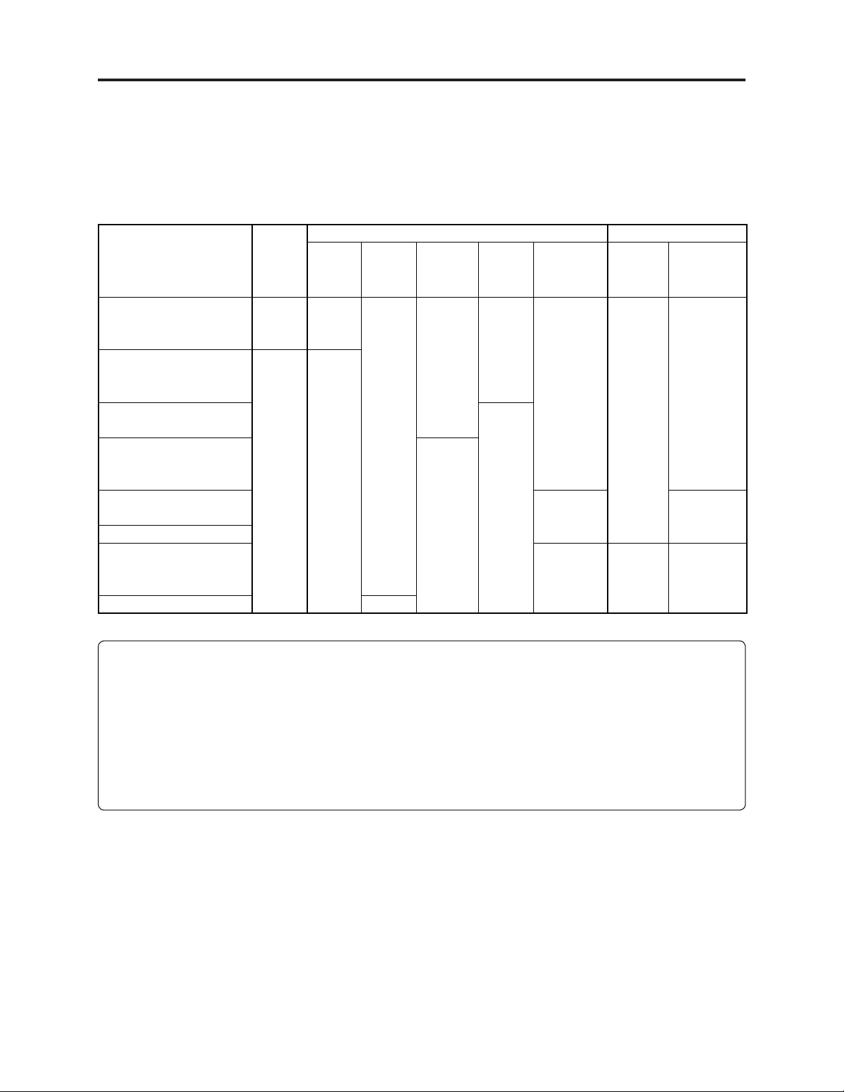
Table 2-6-1 List of Compatible Recording Media
8 cm DVD Card
Model HDD
DZ-HS303E/HS303SW/
HS301E/HS301SW/
HS300E
DZ-GX3300E/GX3200E/
GX3100E/BX37E/
BX35E/MV4000E
DZ-MV730ME/
DZ-BX31E
DZ-GX20E/MV780E/
MV750E/V730E/
MV3000E/MV2000E
DZ-MV580E/V550E/
MV1000E.
DZ-MV380E/V350E
DZ-MV270E/V238E/
MV230E/V208E/
MV200E
DZ-MV100E N
M: RP
S: N
M: N
S: N
DVD -
RAM
M: RP
S: P
M: RP
S: RP
DVD-R DVD-RW +RW Note
M: RP
S: N
M: RP
S: N
M: Movie
S: Still
RP: Recording/Playback possible
P: Only playback possible
N: Non-compatibility
SD
memory
card
M: RP
S: N
N
N
No holder/
cartridge/
caddy case
needed
Holder
needed
Cartridge/
caddy case
needed
M: N
S: RP
NN
Multimedia
card
N
M: N
S: RP
Note:
1) Do not use a DVD formatted on a device other than DZ-MV4000E/GX3300E/GX3200E/GX3100E/
BX37E/BX35E: Such a DVD may be recordable, but it cannot be played back.
2) Do not insert a DVD not fi nalized into other device (except Hitachi DVD recorders or Hitachi
DVD video camera/recorders): Simple insertion itself may disable additional recording, playback
or fi nalization.
3) Be sure to fi nalize a DVD on the same device used for recording: Finalizing it on another device
could make it unplayable.
2 - 14
Page 25
General Description > Names of Parts
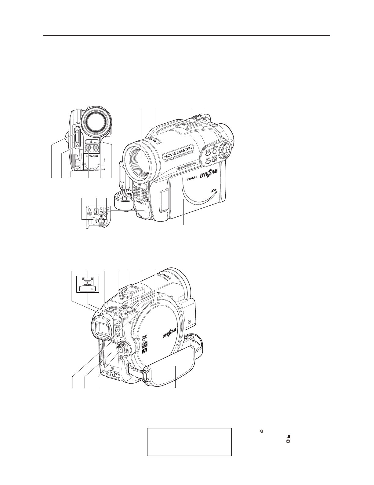
2-7 Names of Parts
23 4 51
11
(Inside the cover)
16 17 182219
23 24 26 27
13
6
1312
25
78 9
14
21
2015
Although the external appearances of DZGX3300E, GX3200E, GX3100E, BX37E
BX35E and MV4000E are different, the method
of operating these models is identical. DZGX3300E illustrations are used in this manual.
10
1 Flash (for DZ-GX3300E only)
2 Light receiving sensor
(for DZ-GX3300E only)
This sensor controls the amount of light to be
emitted from the built-in flash. Take care not
to block with hand, etc. during recording.
3 Lens cap string attachment hole
4 Stereo microphone
Take care that the microphone is not blocked
by a hand, etc., during recording.
5 Recording indicator
The red indicator will light during recording.
6 Infrared receiver
(for DZ-GX3300E/GX3200E/GX3100E only)
When the remote control is used to operate
the DVD video camera/recorder, this
receiver will receive the infrared signal.
7 Optical 10× zoom lens
(for DZ-GX3300E/GX3200E only)
Optical 15× zoom lens
(for DZ-GX3100E only)
Optical 25× zoom lens
(for DZ-BX37E/BX35E/MV4000E only)
8 Lens hood (for DZ-GX3300E/GX3200E/
BX37E/BX35E/MV4000E only)
Always remove this lens hood when using
the optional tele-conversion or wideconversion lens.
9 Zoom lever
Push the lever to the T side for telephoto, or
to the W side for wide-angle.
10 Accessory shoe (for DZ-GX3300E/
GX3200E only)
The optional video flash can be attached
here. (See the instruction manual of device to
be attached for details.)
11 PC connection terminal (TO PC) (for DZ-
GX3300E/GX3200E/GX3100E/BX37E only)
12 AV input/output jack
13 External microphone jack (for DZ-
GX3300E/GX3200E/GX3100E only)
14 Wide-screen color liquid crystal display
(inside)
15 Viewfinder
16 Diopter control
To adjust the focus of image appearing in the
viewfinder. (Pull out the viewfinder.)
17 SLEEP/RESTART button
To switch the sleep/restart status between
ON and OFF.
18 ACCESS/PC indicator
(for DZ-GX3300E/GX3200E/GX3100E/
BX37E only)
ACCESS indicator (for DZ-BX35E/MV4000E only)
Will blink or light when the disc in DVD
video camera/recorder is accessed (write or
read is executed) or the DVD video camera/
recorder is connected to PC.
19 PHOTO button
20 DISC EJECT button
Press down and release this button to open
the cover of disc insertion block.
21 Disc insertion block
22 BATTERY EJECT button
Press this button when removing the battery.
23 Battery attachment platform
24 Record button (REC)
25 LOCK switch
It is recommended that you set the LOCK
switch to (to the upper position) to prevent
LOCK
the power switch in the “ ” position from
accidentally moving to “ ”.
26 Power switch
27 Hand strap
2 - 15
Page 26
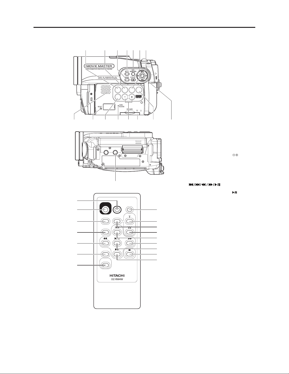
General Description > Names of Parts
44
45
46
47
48
49
50
28
29 30 31 32 33 34
(1%75
(+0#.+<'
':21574'
$.%
81.
&+52.#;
43
4'%
2*161
&+52.#;
&+)+6#.
<11/
<11/
/'07
5'.'%6
&'.'6'
&+5%
0#8+)#6+10
28 FINALIZE button
Press this button to finalize the recorded
DVD-RW/DVD-R/+RW.
29 FOCUS button
To switch between manual focus and autofocus.
30 MENU button
Press this button to display the menu for
setting camera functions and Disc
Navigation.
31 SELECT button
32 DISC NAVIGATION button
33 STOP/EXIT button
To end playback or cancel setting of menu.
34 EXPOSURE button
Press this button to adjust the exposure.
35 Speaker
36 RESET button
14533738394036
42
51
52
53
54
55
56
57
58
59
To reset all settings to defaults (status when
the DVD video camera/recorder was
shipped from the factory).
DISPLAY (Screen display) button
37
Press this button to display the details of
image being played back or camera setting
status, or switch the display off.
38 CARD ACCESS indicator
39 Volume control buttons (VOL)/ buttons
To adjust the volume of sound from speaker,
etc.
40 Card insertion block
41 BLC (backlight compensation) button
Press this button when subject is being
lighted from rear.
42 buttons
Use these buttons to select a scene or menu
item, and then press the center ( ) to play
back the scene, or designate an option from
the menu.
43 Tripod threaded hole
Used to attach the DVD video camera/
recorder to a tripod.
44 PHOTO button
45 REC button
46 MENU button
47 SELECT button
48 Reverse search button
49 DELETE button
50 DISC NAVIGATION button
51 DISPLAY button
52 ZOOM T button
53 DIGITAL ZOOM button
54 ZOOM W button
55 Reverse skip button
56 Forward search button
57 Play/pause button
58 Stop button
59 Forward skip button
* The buttons on remote control will function the
same as those on DVD video camera/recorder.
2 - 16
Page 27
General Description > List of Accessories
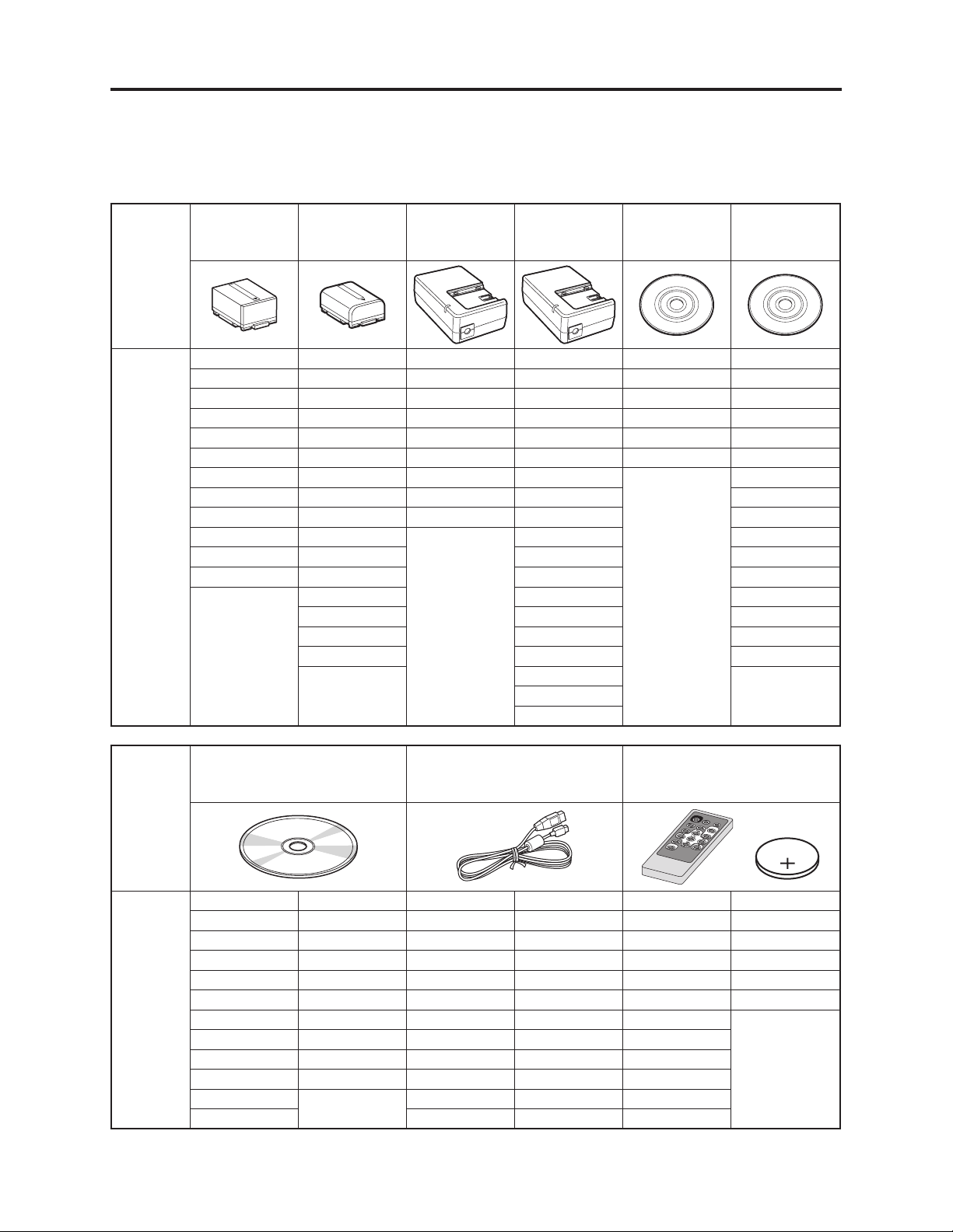
2-8. List of Accessories
The provided accessories vary depending on the model and destination.
In the following table, the prefi x “DZ-“ for model names is omitted:
Accessory
Models
providing
accessory
Battery
DZ-BP14S
GX3300E GX3100E GX3300E GX3300E(AU) GX3300E GX3300E(AU)
GX3300E(UK) GX3100E(UK) GX3300E(UK) GX3300E(SW) GX3300E(UK) GX3300E(SW)
GX3300E(AU) GX3100E(AU) GX3200E GX3300E(SWC) GX3200E GX3300E(SWC)
GX3300E(SW) GX3100E(SW) GX3200E(UK) GX3300E(SWH) GX3200E(UK) GX3300E(SWH)
GX3300E(SWC) GX3100E(SWC) GX3100E GX3200E(AU) GX3100E GX3200E(AU)
GX3300E(SWH) GX3100E(SWH) GX3100E(UK) GX3200E(SW) GX3100E(UK) GX3200E(SW)
GX3200E BX37E BX37E GX3200E(SWC) GX3200E(SWC)
GX3200E(UK) BX37E(AU) BX35E GX3200E(SWH) GX3200E(SWH)
GX3200E(AU) BX37E(SW) BX35E(UK) GX3100E(AU) GX3100E(AU)
GX3200E(SW) BX37E(SWC) GX3100E(SW) GX3100E(SW)
GX3200E(SWC) BX37E(SWH) GX3100E(SWC) GX3100E(SWC)
GX3200E(SWH) BX35E GX3100E(SWH) GX3100E(SWH)
Battery
DZ-BP07PW
BX35E(UK) BX37E(AU) BX37E(AU)
BX35E(AU) BX37E(SW) BX37E(SW)
BX35E(SW) BX37E(SWC) BX37E(SWC)
BX35E(SWH) BX37E(SWH) BX37E(SWH)
AC Adapter/
Charger
DZ-ACS3(E)
AC Adapter/
Charger
DZ-ACS3(SW)
BX35E(AU)
BX35E(SW)
BX35E(SWH)
Single-sided
8cm
DVD- R
Single-sided
8cm
DVD-RAM
Accessory
Models
providing
accessory
Software
CD-ROM
GX3300E GX3100E GX3300E GX3100E GX3300E GX3100E
GX3300E(UK) GX3100E(UK) GX3300E(UK) GX3100E(UK) GX3300E(UK) GX3100E(UK)
GX3300E(AU) GX3100E(AU) GX3300E(AU) GX3100E(AU) GX3300E(AU) GX3100E(AU)
GX3300E(SW) GX3100E(SW) GX3300E(SW) GX3100E(SW) GX3300E(SW) GX3100E(SW)
GX3300E(SWC) GX3100E(SWC) GX3300E(SWC) GX3100E(SWC) GX3300E(SWC) GX3100E(SWC)
GX3300E(SWH) GX3100E(SWH) GX3300E(SWH) GX3100E(SWH) GX3300E(SWH) GX3100E(SWH)
GX3200E BX37E(AU) GX3200E BX37E GX3200E
GX3200E(UK) BX37E(SW) GX3200E(UK) BX37E(AU) GX3200E(UK)
GX3200E(AU) BX37E(SWC) GX3200E(AU) BX37E(SW) GX3200E(AU)
GX3200E(SW) BX37E(SWH) GX3200E(SW) BX37E(SWC) GX3200E(SW)
GX3200E(SWC) GX3200E(SWC) BX37E(SWH) GX3200E(SWC)
GX3200E(SWH) GX3200E(SWH) GX3200E(SWH)
PC connection cable
Infrared remote control
DZ-RM4W & Lithium
Battery CR2032
2 - 17
Page 28
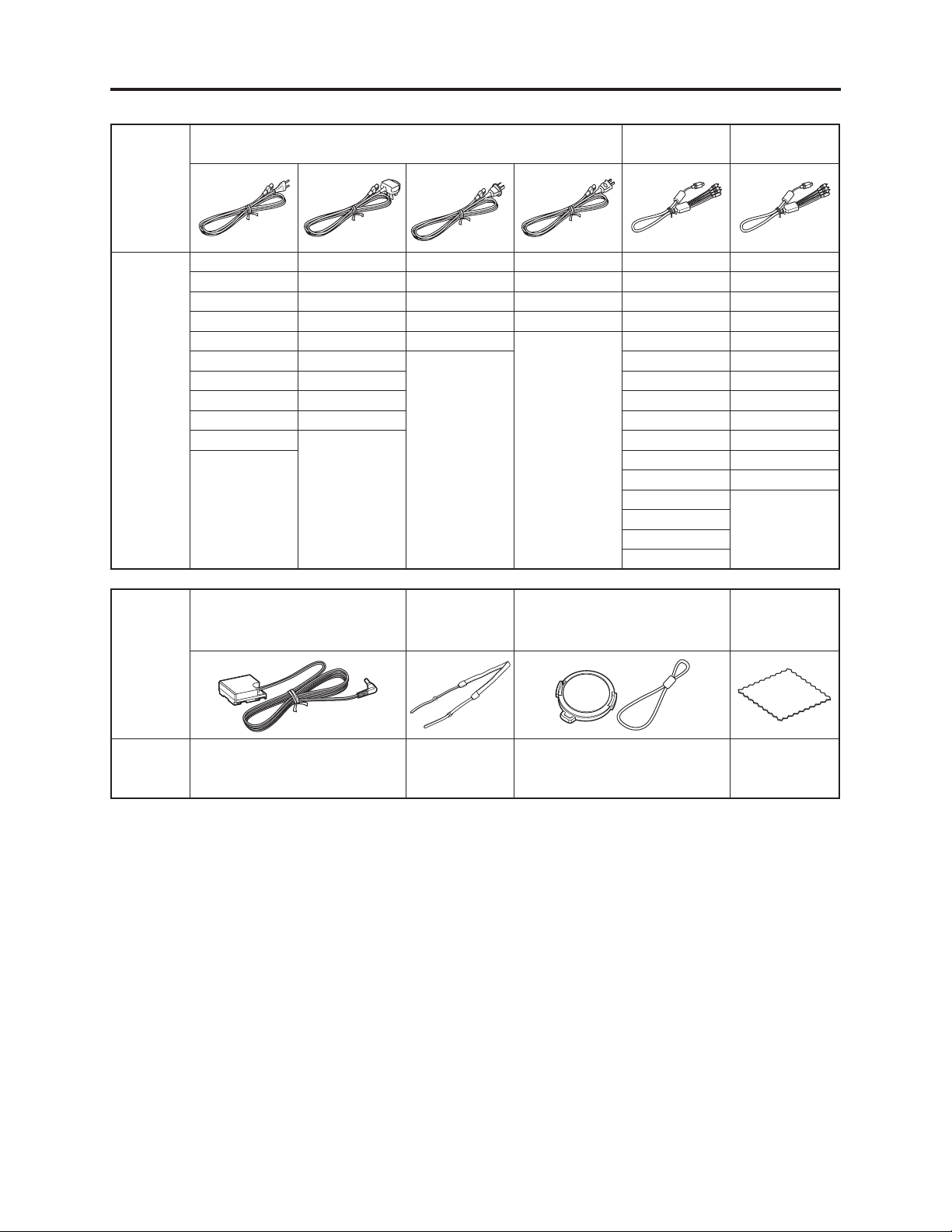
General Description > List of Accessories
Accessory
Models
providing
accessory
Mains lead
GX3300E GX3300E(UK) GX3300E(AU) GX3300E(SWC) GX3300E GX3300E(AU)
GX3300E(SW) GX3300E(SWH) GX3200E(AU) GX3200E(SWC) GX3300E(UK) GX3300E(SW)
GX3200E GX3200E(UK) GX3100E(AU) GX3100E(SWC) GX3200E GX3300E(SWC)
GX3200E(SW) GX3200E(SWH) BX37E(AU) BX37E(SWC) GX3200E(UK) GX3300E(SWH)
GX3100E GX3100E(UK) BX35E(AU) GX3100E GX3200E(AU)
GX3100E(SW) GX3100E(SWH) GX3100E(UK) GX3200E(SW)
BX37E BX37E(SWH) BX37E GX3200E(SWC)
BX37E(SW) BX35E(UK) BX37E(AU) GX3200E(SWH)
BX35E BX35E(SWH) BX37E(SW) GX3100E(AU)
BX35E(SW) BX37E(SWC) GX3100E(SW)
AV/S output
cable
BX37E(SWH) GX3100E(SWC)
BX35E GX3100E(SWH)
BX35E(UK)
BX35E(AU)
BX35E(SW)
BX35E(SWH)
AV/S input/
output cable
Accessory
Models
providing
accessory
DC power cord Shoulder strap Lens cap & Lens cap string
All models All models All models All models
Disc cleanig
cloth
2 - 18
Page 29
General Description > List of Abbreviations and Terms for DVD Video Camera/Recorders
2-9 List of Abbreviations and Terms for DVD Video
Camera/Recorders
Index Abbreviation/Term Explanation
A AC3 See Dolby AC3.
C CPRM Content Protection for Recordable Media: Copyright protection function that is
suitable for online distribution of music.
CSP IC Chip Scale Package IC or Chip Size Package IC: This IC was made compact by
arranging pins under the package.
D DCF Design rule for Camera File system standard: This camera fi le system standard.
Dolby AC3 Audio coding format developed by Dolby Laboratories in U.S, also simply referred
as AC3 format: Supports 5-channel full-range sound and one channel for sub-woofer
sound playback.
Dolby Digital See Dolby AC3.
DPOF Digital Print Order Format: DPOF allows user to record print information along
with photos on storage media to facilitate printing of photos.
DVD Digital Versatile Disc. A huge amount of digital data for video (movie) and audio
can be recorded on this disc, whose size is the same as CD.
DVD-Audio One type of DVD standard disc, on which high-quality audio can be recorded
DVD-R One type of DVD standard disc, to which writing once is possible (recordable type)
DVD-RAM One type of DVD standard disc, to which writing up to 100,000 times is possible
DVD-ROM One type of DVD standard disc, to which data for computer can be recorded
DVD-RW One type of DVD standard disc, to which writing up to 1000 times is possible
DVD-Video One type of DVD standard disc, on which high-quality video and audio can be
recorded
DVD Video
Format
DVD Video Video recording/playback standard that applies to DVD-RAM and DVD-RW: This
Recording Format allows versatile editing functions, differing from the DVD Video Format.
DVD-VR Format See DVD Video Recording Format.
DVD+RW
Video Format
E Exif Exchangeable image fi le format. File format used for recording photos on digital
F FireWire See IEEE1394.
FNR Frame Noise Reducer: This function or circuit automatically recognizes noise that
I IEEE1394 Also referred to as FireWire or i-LINK: Standard for serial interface that connects
Interlaced CCD This CCD scans one image twice (scans roughly once and interpolates between fi rst
i-LINK See IEEE1394.
J JPEG Joint Photographic Expert Group: International standard format for compressing
L LCD Liquid Crystal Display. LCD formats include STN and TFT.
LPCM Linear Pulse Code Modulation. Also referred to as linear PCM. LPCM is a format
Video recording/playback standard that applies to DVD-Video, DVD-R and DVD-
RW
Video recording/playback format for +RW was developed by DVD industry
organization “DVD+RW Alliance”, which is different from the DVD Forum.
cameras.
randomly occurs between frames and removes it.
PC and peripheral devices
scanning lines the second time) and interlaces the images obtained by scanning
twice to create a one-image signal.
still images
that digitizes analog audio data during recording and converts it to analog data
during playback.
2 - 19
Page 30
General Description > List of Abbreviations and Terms for DVD Video Camera/Recorders
Index Abbreviation/Term Explanation
M MMC See MultiMediaCard.
MPEG Motion Picture Experts Group: Standard related to compression of digital video
and audio. MPEG2 is a higher standard of MPEG and is applied to video (movie)
requiring higher quality.
MPEG Audio
Layer 2
MultiMediaCard Also referred to as MMC. Compact memory card, 32 mm long × 24 mm wide × 1.4
S SCSI Small Computer System Interface: A standard for connecting computer and
SDMI Secure Digital Music Initiative: This conference was established by hardware
SD Memory Card Formally named Secure Digital Memory Card. This compact memory card, 32
SecureMMC See Secure MultiMediaCard.
Secure Also referred to as SecureMMC. This compact memory card has multimedia card
MultiMediaCard specifi cations, to which an advanced copyright protection function is added.
Software discProtect
STN LCD Super-Twisted Nematic Liquid Crystal Display: This type of color LCD is inferior to
T TFT LCD Thin Film Transistor Liquid Crystal Display: This type of color LCD features clear
U UDF Universal Disc Format, which is a fi le format of recordable disc defi ned by OSTA.
USB Universal Serial Bus: Standard of serial interface that connects PC and peripheral
V VBR Stands for Variable Bit Rate: This format of coding audio and video varies the
Etc. +R Digital discs whose specifi cations are established and promulgated by “DVD+RW
+RW
One of three audio compression standards (layers 1-3) defi ned by MPEG
mm thick
peripheral devices. The number, First, Ultra, Wide, etc., prefi xed or suffi xed to
SCSI indicates the data transfer rate and connector specifi cations.
makers, the Recording Industry Association of America (RIAA) and music industry
companies, to protect copyrights of musical compositions.
mm long × 24 mm wide × 2.1 mm thick, is equipped with an advanced copyright
protection function.
This function writes the protect information to DVD-RAM disc to prevent accidental
erasure. Software Disc-Protect is included in DVD-RAM disc specifi cations defi ned
by DVD Forum.
TFT LCD in coloring, view angle, etc.
display, high contrast, wide view angle, etc.
The revision 2.01 UDF is used on DVD video camera/recorder.
devices. Two versions - USB1.1 and USB2.0, with different data transfer rates -
exist at present.
amount of data depending on the subject image.
Alliance”, which is an industrial group different from “DVD Forum”. +R is
recordable, and +RW is rewritable. They are also referred to as DVD+R and
DVD+RW.
2 - 20
Page 31

3
Description of Operation
3-1 Description of Structure
(1) Differences in structure
The shapes and assembly methods of L case, R case, front case, lens cover, etc. are different among
DZ-GX3300E/GX3200E/GX3100E/BX37E/BX35E/MV4000E for the following reasons:
1) The size and shape of lens unit are different because the size of CCD image sensor is different.
2) Whether the fl ash and accessory shoe are provided or not.
(2) Major circuit boards and units
The DZ-GX3300E/GX3200E/GX3100E/BX37E/BX35E/MV4000E include the following boards and units:
(a)
Disc drive unit (DRG circuit board):
The DRG circuit board in unit incorporates the disc drive circuit and the power supply circuit
of the entire DVD video camera/recorder.
(b)
Lens unit
(c)
EVF unit
(d)
LCD unit (LCD circuit board):
The LCD circuit board in unit incorporates the LCD monitor drive and backlight drive
circuits.
(e)
AVJ-H/M/L circuit board:
Incorporates the AV input/output, PC connection and external microphone terminals.
H is for DZ-GX3300E/GX3200E; M for DZ-GX3100E; and L for DZ-BX37E/BX35E/MV4000E.
(f)
FRT-H/M/L circuit board:
Incorporates the white balance (WB) sensor, remote infrared receiver (IR) sensor, etc. The
FRT-H circuit board in DZ-GX3300E also has a fl ash circuit.
H is for DZ-GX3300E/GX3200E; M for DZ-GX3100E; and L for DZ-BX37E/BX35E/MV4000E.
(g)
GSL-3M/2M/1M/L circuit board:
This circuit board connects the CCD image sensor to MAN circuit board. It incorporates an
EIS sensor, CCD drive IC, etc.
3M is for DZ-GX3300E; 2M for DZ-GX3200E; 1M for DZ-GX3100E; and L for DZ-BX37E/
BX35E/MV4000E.
(h)
LMF-H/M/L circuit board:
This circuit board connects the circuit board (incorporating a card slot) in L case to MAN
circuit board.
H is for DZ-GX3300E/GX3200E; M for DZ-GX3100E; and L for DZ-BX37E/BX35E/MV4000E.
(i)
MAN circuit board:
Incorporates the circuits that control the entire DVD video camera/recorder and the video/
audio signal processing circuits.
(j)
SHE-H circuit board:
This circuit board connects the accessory shoe control/power supply terminal to MAN circuit
board.
It is not mounted in DZ-GX3100E, which does not have a control/power supply terminal, or
DZ-BX37E/BX35E/MV4000E, which does not have an accessory shoe.
3 - 1
Page 32

Description of Operation > Description of Structure / Description of Newly Adapted
(a) Disc drive unit
(b) Lens unit
(c) EVF unit
(d) LCD unit
(e) AVJ-H/M/L
circuit board
(f) FRT-H/M/L
circuit board
(g) GSL-3M/2M/1M/L
circuit board
(h) LMF-H/M/L
circuit board
(i) MAN circuit board
(j) SHE-H circuit board
(a)
(e)
(f)
(d)
(b)
(h)
(g)
(j)
(i)
Fig. 3-1-1 Confi guration of circuit boards and their mounting locations
3-2 Description of Newly Adapted Technology
3-2-1 Features and Format of +RW
A +RW is a disc that can be written approx. 1000 times. The “DVD+RW Alliance” establishes its
specifi cations: These specifi cations are similar to those of DVD-RW, but the wobble and address
data recording format are different.
“Wobble” refers to the frequency of groove which is provided to guide a pickup. The +RW address
data is recorded and superimposed on this groove; the DVD-RW address data is recorded in an area
that is called a “land” between the grooves.
(c)
Table 3-2-1 Comparison of Specifi cations between +RW and DVD-RW
ł
: Same as on left column
Item +RW (single layer) DVD-RW
Disc diameter 12cm 8cm 12cm 8cm
Storage capacity 4.7GB/ side 1.46GB/ side 4.7GB/ side 1.46GB/ side
Thickness of disc 1.2mm ł
Rewritable number of times At least 1000 ł
Refl ectance ratio 18 - 30% ł
Track width 0.74Ǎm ł
Recording/playback
laser wavelength
Wobble 817kHz 140kHz
Address data recording format LPP (Land Pre-Pit) ADIP (Address In Pre-groove)
650nm ł
3 - 2
Page 33

Description of Operation > Description of Newly Adapted Technology
3-2-2 SLEEP/RESTART button (SLEEP status)
Pressing the SLEEP/RESTART button in the recording pause status
will transfer the DVD video camera/recorder to the SLEEP status.
The “SLEEP status” refers to the status in which the recording pause
status is maintained using minimum power. In the ordinary recording
pause status, the LCD monitor or viewfi nder is left on, but it is off in
SLEEP status.
The SLEEP status will be held up to approx.
30 minutes regardless of the Power Save setting; after 30 minutes, the
DVD video camera/recorder will turn off.
There are two ways to release the SLEEP status and restart recording:
•Press the SLEEP/RESTART button, and then press the RECORD
button.
•Press the RECORD button twice.
Set the power switch to OFF to release the SLEEP status and turn the
DVD video camera/recorder off.
3-2-3 Still capturing function
This function records an image of movie being played back on SD
memory card as a still (JPEG).
Perform the following during playback of movie. The DVD video
camera/recorder will enter the playback pause status and shift to the
still capturing mode:
•Press the PHOTO button.
•Press the MENU button, and then choose and execute “Edit” –
“PHOTO Capture” in playback menu.
The number of pixels for a still captured from a 4:3 movie will be 640 (H)
x 480 (V); that for a still captured from a 16:9 movie will be 640 (H) x
360 (V).
3,%%02%34!24
"544/.
Fig. 3-2-1
0(/4/
"544/.
3 - 3
Fig. 3-2-2
Page 34

4
Troubleshooting
4-1 Procedure for Troubleshooting
Perform troubleshooting in the order shown in Fig. 4-1-1.
Note:
1) Before troubleshooting or servicing, be sure to obtain customer approval for the following:
a) The recorded contents on disc may be lost depending on the details and situation of fault
(defect).
b) The date/time and various settings, including video recording mode, designated by customer
after purchase, may be reset to the defaults before purchase (factory settings).
2) Perform “4-7-2 System reset procedure” after repair is completed: Note that system reset will
erase all error codes that will be necessary for troubleshooting.
3) Take notes of settings on received product in the Remarks and Memo columns, referring to “Table
4-7-1 List of items to be reset”: These notes will be necessary not only for reset, but for checking
any defects that occur under the particular setting conditions.
No improvement
Check
phenomenon
Updating
needed
*1: Messages and error codes will appear on LCD monitor or in viewfi nder.
No message
appears
Message
appears
Check firmware
version
(section 4-4-1)
Update firmware
(section 4-4-2)
(*1)
(*1)
Messages and
Troubleshooting
(section 4-2)
Updating
unneeded
Trouble
Diagnosis
(section 4-5)
No improvement
after updating
No improvement
Display of Error
Codes and
Restriction
(section 4-3)
Check
troubleshooting
with the factory
Error codes not included in
service manual appear
Check
troubleshooting
with the factory
No improvement
: Phenomenon
: Troubleshooting
: Check
( )
: Refer to section
Fig. 4-1-1
4 - 1
Page 35

Troubleshooting > Messages and Troubleshooting
4-2 Messages and Troubleshooting
Some messages may appear on the LCD screen or in the viewfi nder during operation. If a message
appears, check the following, and then perform the appropriate action, according to the message
content:
1) Is the disc bottom/surface reversed when using a single-sided disc?
If so, reload the disc properly.
2) Is there any condensation on the lens or in the disc drive unit of DVD video camera/recorder?
Condensation will occur when the DVD video camera/recorder is moved from a cold place to a warm place,
e.g. If condensation occurs, set the power switch to “OFF” with the disc loaded, and then leave the DVD
video camera/recorder in a dry place until condensation disappears (for 1-2 or more hours).
The messages divided using broken lines in the table can be displayed in sequence from the upper
row by pressing the
button.
Message
Cannot combine scene. Appears if an attempt is made to
combine unconnected scenes: The
specifi cations state that combining of
only multiple scenes is possible.
Cannot combine scene of
multiple programs.
Create Playlist fi rst,
and then combine scenes.
Cannot combine.
Deselect PHOTO scenes.
Cannot combine.
Select multiple scenes.
Cannot delete scenes. Appears when user performed deletion
Cannot execute.
Change display
category to All.
Appears when combining the scenes in
different programs was attempted.
Appears if an attempt is made to
combine scenes when a photo was
selected: The specifi cation state that
combining of only video scenes is
possible.
Appears when combining one scene was
attempted.
at the upper limit of 999 scenes
registered.
Appears when combining or moving
scenes was instructed with “Category:
Movie or Still” specifi ed.
Cause/condition for
message to appear
(*1)
Troubleshooting
Stop trying to combine scenes, or
create a play list containing the
scenes to be combined, and combine
them on the play list.
When combining those scenes, fi rst
create a play list, and then combine
the scenes on it.
Select only video scenes, or stop
trying to combine scenes.
Select multiple scenes and then
combine them.
Combine divided scenes, and then
delete if necessary.
Specify “Category: All”, and then
operate the DVD video camera/
recorder again.
(*2)
*1: The DVD video recording format defi nes the maximum number of entry points as 999: Since one entry
point is allocated to one scene, the maximum number of scenes recordable on disc with the DVD video
camera/recorder is 999.
*2:
If recording is continued without editing, one scene will comprise one cell for each entry point.
When scenes are combined, only the number of entry points will decrease (only the entry point is deleted);
the number of cells will not decrease. Assume, for example, that the number of cells before
scenes are combined is 999, which is the upper limit defi ned by the DVD video recording format. If a
scene comprising one cell is divided at two points and the scene between the divided scenes needs to be
deleted, the cell must be further divided in order to delete. However, since the number of cells has reached
the upper limit in this case, the cell cannot be divided and the scene cannot be deleted.
4 - 2
Page 36

Troubleshooting > Messages and Troubleshooting
Message
Cannot execute.
Unselect multiple scenes.
Cannot read disc.
Check dirt/crack/bothside
contrary/inserted correctly.
CANNOT RECORD
PHOTOS.
Cannot replace thumbnail
on PHOTO scenes.
Cannot select any more
scenes
CARD ALMOST FULL Appears when the remaining number of
Card error has occurred.
Format the card now?
Card error. Appears when the card cannot be
Card error has occurred.
Formatting is not complete.
Card error has occurred.
Keep card inside & restart.
Card full. Appears when the recording capacity of
Appears if an attempt is made to
select multiple scenes for division: The
specifi cations state that dividing
multiple scenes is impossible.
Appears when reading or writing any
recorded fi les cannot be done due to dirt
on disc.
Appears when a warped or distorted
disc,
or a logically damaged disc, whose
initialization was previously interrupted,
is loaded.
Appears if an attempt is made to record
stills on DVD-RW/DVD-R/+RW: The
specifi cations state that no still is
recordable on DVD-RW/DVD-R/+RW.
Appears when a photo thumbnail was
selected for change in scene editing
menu: The specifi cations stipulate that
the thumbnail of still cannot be changed.
Appears when the number of scenes
selected on card has exceeded the upper
limit of 999 scenes.
recordable stills has reached less than
10 during recording.
Appears when a card initialized on PC,
etc., or a card whose initialization was
interrupted before, is loaded.
recognized because its terminals are
dirty.
Also appears when data other than
photos is recorded on card.
Appears when a damaged card is
initialized.
Appears when an error occurred during
editing of movie fi les.
card has reached the limit during
recording.
Appears when a card whose remaining
recording capacity is small, and on
which no still can be recorded, is loaded.
Appears when the remaining capacity of
card has reached the recordable limit.
Cause/condition for
message to appear
Troubleshooting
Divide scenes one by one.
Refer to “4-3-5 Cleaning disc and
optical pickup” and clean the disc.
Or replace the disc.
Replace the disc.
Use a DVD-RAM or card when
recording photos.
Select a movie to change the
thumbnail.
Release the selection of unnecessary
scenes.
Prepare another card, or delete
unnecessary stills.
Choose “YES” and designate it to
initialize the card (deleting all
recorded data).
Use a dry cloth to clean the card
terminals.
Replace the card.
Replace the card.
Set the power switch to “ OFF”, and
after several seconds, set it to “Card
Still”.
Replace the card, or delete
unnecessary stills.
Replace the card, or delete
unnecessary stills.
Replace the card, or delete
unnecessary stills.
4 - 3
Page 37

Troubleshooting > Messages and Troubleshooting
Message
Card is not formatted.
Format the card now?
YES NO
CHECK DISC Appears when disc that cannot be
Control Information Error. Also appears when reading or writing
COPY PROTECTED Appears if an attempt is made to record
Data error in a part of image
fi le.
Repair data now?
YES NO
Appears when an unformatted card or a
card formatted on PC was loaded.
used onthat cannot be used on the DZGX3300E/GX3200E/GX3100E/BX37E/
BX35E/MV4000E, or logically damaged
disc (warped or distorted), was loaded.
If the type of disc is acceptable, and
there is no scratch or distortion, the disc
may be defective.
from/to recorded fi le cannot be performed
because the disc is dirty.
Appears when mismatch between
recorded scene and scene information
occurs. Such a mismatch occurs when
editing is performed near the limit of
disc storage capacity, or when the control
information fi le is operated using a
device other than the DZ-GX3300E/
GX3200E/GX3100E/BX37/35E/MV4000E.
copy-guarded image. The specifi cations
state that copy-guarded image cannot
be recorded on the DVD video camera/
recorder.
Appears when reading/writing of
recorded fi les cannot be performed
because the disc is dirty. If the message
appears immediately after recognition of
a loaded, recorded disc was fi nished, fi rst
check for dirt on disc
Appears if writing to fi le cannot be
completed normally because power
was turned off by mistake during movie
recording or editing, and an abnormality
in part of the fi le is recognized.
Cause/condition for
message to appear
Troubleshooting
Choose “YES” and designate it when
formatting card (deleting all recorded
data).
Check the type of disc, and for
scratch or distortion on disc: If the
disc is scratched or distorted, replace
it.
Replace the disc.
Refer to “4-3-5 Cleaning disc and
optical pickup” and clean the disc.
Or replace the disc.
Update the control information.
(Start Disc Navigation, press the
MENU button, and then execute
“Update Control Info.” in the “Disc”
menu.
Stop trying to record.
Refer to “4-3-5 Cleaning disc and
optical pickup” and clean the disc.
Or replace the disc.
Choose “YES” and designate partial
repair (automatic repair) of movie
fi le. Choosing “NO” will display a
message for verifying initialization.
[Refer to *3 page 4-5]
4 - 4
Page 38

Troubleshooting > Messages and Troubleshooting
Message
Data error in all image fi le.
Repair all data now?
YES NO
DISC ACCESS This message appears during normal
Appears when reading/writing of
recorded fi les cannot be performed
because the disc is dirty. If the message
appears immediately after recognition of
a loaded, recorded disc was fi nished, fi rst
check for dirt on disc
Appears if writing to fi le cannot be
completed normally because power
was turned off by mistake during movie
recording or editing, and it is recognized
that the movie fi le must be totally
repaired.
operation process, when the DVD video
camera/recorder checks whether a
proper disc has been loaded or not. It is
displayed for a longer time period when
the date has changed.
This message appears during normal
operation process, when the recorded
images are being stored on disc.
Cause/condition for
message to appear
Troubleshooting
Refer to “4-3-5 Cleaning disc and
optical pickup” and clean the disc.
Or replace the disc.
Choose “YES” and designate total
repair (automatic repair) of movie
fi le. Choosing “NO” will display a
message for verifying initialization.
[Refer to *3]
Operate the DVD video camera/
recorder after the message disappears.
Operate the DVD video camera/
recorder after the message disappears.
*3: Take care with the following when repairing video fi le:
a) If any message appears when the power switch was moved from “OFF” to “Movie” or “Disc Still” with
the disc left loaded after camera recording, choose repair.
b) If recording and playback are possible with another disc, which is free from condensation or dirt, choose
repair.
c) Be sure to connect the AC adapter/charger: The specifi cations state that repair is possible only when the
AC adapter/charger is connected.
d) Although repair is normally fi nished in several minutes, it could take approx. one hour.
e) If the disc is removed while it is being recognized, the repair function of movie fi le will be invalid.
f) If the timing when power is turned off is inappropriate, normal repair may be impossible.
g) If the disc contains data recorded on a device other than DZ-GX3300E/GX3200E/GX3100E/BX37E/
BX35E/MV4000E, normal repair may not be possible.
h) The repaired data may be different from the original recorded content because of partial deletion of a
defective portion.
i) The repaired data (only corrected portion in case of partial repair) will lose the original date/time
information because the information for date/time when repair was executed will be added.
j) If “all repair” is executed, repair will be made in the order of all videos and all photos, and the time-
sequential relationship of recorded contents may be lost.
4 - 5
Page 39

Troubleshooting > Messages and Troubleshooting
Message
Disc error has occurred.
Finalizing is not complete.
Disc error has occurred.
Format the disc now?
YES NO
Disc error has occurred.
Formatting is not complete.
Disc error has occurred.
Keep disc inside & restart.
Cause/condition for
message to appear
Appears when the disc could not be
fi nalized because it was dirty.
Appears if accident, such as power off,
has occurred during fi nalizing.
If the message still appears even when
the disc has been cleaned and fi nalized
again and again, the disc may be
defective.
Appears when reading or writing from/to
recorded fi le cannot be performed
because the disc is dirty.
Appears when a DVD-RAM/DVD-RW/
+RW initialized on PC, etc., or a card
whose initialization was suspended
before, is loaded.
Appears when the disc could not be
normally formatted because it was dirty.
Also appears when a warped or distorted
disc was loaded, or a logically damaged
disc whose formatting was suspended is
loaded.
Appears if a problem has occurred
during editing of movie fi le.
Troubleshooting
Refer to “4-3-5 Cleaning disc and
optical pickup” and clean the disc.
Or replace the disc.
Set the power switch to “ OFF” and
reconnect the AC adapter/charger;
then set the power switch to “Movie”
and start fi nalizing again. Or press
the DISC EJECT button, reload the
disc, and then execute fi nalizing.
Replace the disc.
Refer to “4-3-5 Cleaning disc and
optical pickup” and clean the disc.
Or replace the disc.
Choose “YES” and designate it to
initialize the DVD-RAM/DVD-RW/
+RW (deleting all recorded data).
Refer to “4-3-5 Cleaning disc and
optical pickup” and clean the disc.
Or replace the disc.
Replace the disc.
Exit the Disc Navigation function
and set the power switch to “OFF”
with the disc loaded; then reconnect
the AC adapter/charger and set the
power switch to “Movie” or “Disc
Still” (The DVD video camera/
recorder will automatically repair
the video fi le.)
4 - 6
Page 40

Troubleshooting > Messages and Troubleshooting
Message
Disc error has occurred.
Unfi nalize is not completed.
Disc error has occurred. Also appears when reading or writing
Disc full.
Cannot execute.
Disc has no data. Appears when playback or editing is
Disc has no Play List. Appears if switching of play list is
Disc includes protected
scenes.
Delete scenes?
YES NO
Disc is full.
Cannot add control info.
Appears when a recorded fi le cannot
be read or written. If no recovery is
made even when the disc is cleaned
or unfi nalized again, the disc may be
defective.
Appears when an accident, such as
power off, occurred during unfi nalizing.
If no recovery is made even when the
disc is cleaned or unfi nalized again, the
disc may be defective.
from/to recorded fi le cannot be performed
be cause the disc is dirty.
Appears when the disc has been edited
on a device other than the DVD video
camera/recorder, and mismatch has
occurred in recorded data.
Appears if the recording capacity of disc
has reached the limit during editing of
video fi le.
attempted using the Disc Navigation
function with no scene recorded on disc.
selected with no play list registered.
Appears if the loaded disc has a program
(scene) that is write-protected by the
software write-protect function, which is
effective in program units. Although the
DVD video camera/recorder is equipped
with a software disc-protect function
that is effective for disc units, it does not
comply with software write-protect for
program units. (The DVD Forum defi nes
two types of software protect for DVDRAM: disc units and program units.)
Appears when the card contains a scene
write-protected by a device other than
this DVD video camera/recorder.
Appears if the number of scenes on play
list exceeds the upper limit (999) while
control information is being added.
[Refer to *1 page 4-2]
Cause/condition for
message to appear
Troubleshooting
Clean the disc, referring to “4-3-5
Cleaning disc and optical pickup”, or
replace it.
Set the power switch to “OFF”,
reattach the AC adapter/charger,
set the power switch to “Movie”, and
then unfi nalize the disc again. Or,
press the DISC EJECT button to
remove the disc, reload it, and then
unfi nalize it again.
Replace the disc.
Refer to “4-3-5 Cleaning disc and
optical pickup” and clean the disc.
Or replace the disc.
Format the disc (deleting all recorded
data), or replace the disc.
Delete unnecessary scenes, or replace
the disc.
Operate the DVD video camera/
recorder after the message
disappears.
Operate the DVD video camera/
recorder after the message
disappears.
Release the write-protect using the
device that has the software writeprotect function for program units,
or choose “YES” and designate it to
delete the scenes.
Release the write-protect using the
device which set it. Or choose “YES”
and delete the scene.
Delete any unnecessary scenes, or
combine several scenes, and then
operate the DVD video camera/
recorder.
4 - 7
Page 41

Troubleshooting > Messages and Troubleshooting
Message
Disc is not formatted.
Format the disc now?
YES NO
[Displayed only when DVDRW is used]
All data will be deleted.
Select record format.
VR mode VF mode
Drive overheat.
Please retry later.
DVD-R Disc, 16:9 mode
cannot be changed, when
Video mode is STD
DVD-RW (VF) Disc, 16:9
mode cannot be changed,
when Video mode is STD
DVD+RW Disc, 16:9 mode
cannot be changed, when
Video mode is STD
DVD-R Disc, Input Source
cannot be changed.
DVD-RW (VF) Disc, Input
source cannot be changed.
DVD-R Disc , Video mode
and 16:9 mode cannot be
changed.
DVD-RW (VF) Disc, Video
mode and 16:9 mode cannot
be cheanged.
Cause/condition for
message to appear
Appears when a brand-new DVD-RW/
+RW was loaded.
Appears when reading or writing from/to
recorded fi le cannot be performed
because the disc is dirty.
May appear when a disc formatted and
recorded on a device other than DVD
video camera/recorders is loaded.
Appears when an unformatted
DVDRAM/DVD-RW/+RW or one
initialized (other UDF2.0) on PC is
loaded.
Also appears if user rejects partial repair
or total repair of video fi le.
Appears when the temperature inside
the DVD video camera/recorder, or the
temperature of disc, is too high, and
normal operation cannot be executed.
Appears when the wide-screen mode was
chosen with the video quality set to STD
using a DVD-RW (VF mode)/DVD-R/+RW:
The combination of STD (352 × 480
pixels) and wide-mode is prohibited by
the DVD video format.
Appears when an attempt was made to
switch the input with a DVD-RW (VF
mode)/DVD-R recorded in wide mode:
Only the 4:3 aspect screen is possible for
external input.
This is because the DVD video format
prohibits the mixing of 16:9 and 4:3
aspect screens.
Appears when an attempt was made to
change the video quality or wide mode
of recorded DVD-RW (VF mode)/DVD-R.
This is because, if even one scene is
recorded after a disc is formatted, the
specifi cations state that the video quality
or wide mode used for the fi rst recording
will be held on the DVD-RW (VF mode)/
DVD-R.
Troubleshooting
When recording on the DVD video
camera/recorder, choose “YES/
VR Mode/VF Mode” and designate it.
Refer to “4-3-5 Cleaning disc and
optical pickup” and clean the disc.
Or replace the disc.
Use a PC, etc. to check the contents
on disc.
When initializing it (deleting all
recorded data), choose “YES” and
designate it.
Choose “NO” and designate partial
repair or total repair. When
initializing it (deleting all recorded
data), choose “YES” and designate it.
Set the power switch to “OFF” with
the disc loaded, and then leave the
DVD video camera/recorder in a
well-ventilated place until the inside
temperature decreases.
Change the video quality to XTRA or
FINE when using a brand-new DVDRW/DVD-R/+RW. If the DVD-RW/
DVD-R/+RW has already been
recorded in STD mode, replace it.
Stop trying to switch the input, or
replace the disc.
Stop trying to change the video
quality or wide mode, or replace the
disc.
4 - 8
Page 42

Troubleshooting > Messages and Troubleshooting
Message
DVD-RAM disc. Finalize is
not required.
END OF DISC Appears if the disc recordable capacity
Error occurred.
Please replace disc or format
disc
Error occurred.
Please replace disc.
Finalize may not be
complete.
Finalize again now?
YES NO
Found error in image fi le.
Repair disc now?
YES NO
It is unrecordable on this
card.
JPEG fi les related to scenes
are not found.
Must be fi nalize before this
disc canbe played back DVD
player or DVD recorder
Appears when the FINALIZE button
was pressed with a DVD-RAM used.
has reached the limit during recording.
Also appears when reading or writing
from/to recorded fi le cannot be performed
because the disc is dirty.
Appears if repair has failed with DVDRAM/DVD-RW/+RW after message
“Data error in all image fi le. Repair all
data now?” or “Found error in image fi le.
Repair data now?” appeared.
Appears if repair has failed with DVD-R
after message “Data error in all image
fi le. Repair all data now?” or “Found
error in image fi le. Repair data now?”
appeared.
Appears if accident, such as power off,
occurred during fi nalizing, and then
power was turned on again or disc was
reloaded.
Appears if repair has failed after
message
“Data error in a part of image fi le.
Repair disc now?” appeared.
Appears when a card other than SD
memory card was loaded.
Appears when an attempt is made to
copy photos on disc to card, when photo
(JPEG) fi le to be copied is not stored on
disc.
When the DVD video camera/recorder
records a photo on disc, two photo fi les
will be stored on disc - a photo
(conforming to DVD video recording
format) fi le to be displayed on the DVD
video camera/recorder, and a photo
(JPEG) fi le for storage that is linked
to the photo for display. This message
will appear when only the photo fi le for
storage has been deleted on PC, etc.
Appears when a DVD-RW (VF-mode)/
DVD-R/+RW not fi nalized was removed.
Cause/condition for
message to appear
Troubleshooting
A DVD-RAM does not need to be
fi nalized: Wait until the message
disappears.
Replace the disc.
Refer to “4-3-5 Cleaning disc and
optical pickup” and clean the disc.
Or replace the disc.
Initialize the disc (deleting all
recorded data), or replace the disc.
Replace the disc.
Choose “YES” and designate it to
fi nalize the disc.
Choose “YES” and designate total
repair (automatic repair) of video fi le.
Choosing “NO” will display a
message for verifying initialization.
[Refer to *3 on page 4-5]
Insert an SD memory card.
Copy photos to card via PC. The
photo (JPEG) fi le for storage is stored
in DCIM\100HPNX1 folder.
Stop trying to stop copy when a fi le is
being deleted.
If the fi le name was changed, use the
PC to restore the original fi le name,
or copy the fi le via the PC.
Finalize it before playing back on
another DVD device.
4 - 9
Page 43

Troubleshooting > Messages and Troubleshooting
Message
NO DISC Appears if no disc is loaded. Load a disc
Appears when a disc that cannot be used
on the DVD video camera/recorder has
been loaded.
Appears when the disc was not properly
attached to the turntable.
If any of the above does not apply, the
DVD video camera/recorder may be
faulty.
No more scenes.
Play List was deleted.
Play Lists over limit. Appears if an attempt is made to create
Same scenes on Play List
will be deleted.
Delete scenes?
YES NO
Scenes over limit.
Cannot add scene.
Scenes over limit.
Cannot divide scene.
Scenes over limit.
Cannot move scene.
Stop processing. This message appears during operation
Appears during user operation; all
recorded scenes have been deleted and
cleared. The specifi cations stipulate that
a play list with no scene on it cannot be
held: If all registered scenes have been
deleted, the play list will also be deleted.
a new play list or edit play list after
the number of registered play lists
has reached the upper limit (99) that
is defi ned by the DVD video recording
format.
This message appears during user
operation, if even one play list has been
created during scene deletion. This
message does not appear when a scene is
deleted from play list.
Appears if an attempt is made to register
a new scene in play list, with the
specifi ed 999 upper limit scenes
registered. [Refer to *1 page 4-2]
Appears if an attempt is made to divide
a scene with the specifi ed 999 upper
limit scenes registered, or the number
of scenes will exceed 999 with division.
[Refer to *1 page 4-2]
Appears if an attempt is made to move
a scene at the upper limit of 999 scenes
registered, or the number of scenes will
exceed 999 by moving a scene. [Refer to
*1 page 4-2]
process. It will appear when user
interrupted any process by pressing
the stop/cancel button when processing
multiple scenes, etc.
Cause/condition for
message to appear
Check the type of disc, and load a
disc
that can be used on this DVD video
camera/recorder.
Attach the disc properly.
Refer to “4-5 Trouble Diagnosis ”.
Operate the DVD video camera/
recorder after the message
disappears.
Delete unnecessary scenes before
creating a new play list or editing
play list.
Choose “YES” and designate it to
delete selected scenes.
Delete unnecessary scenes from play
list before adding a new scene to it.
Delete unnecessary scenes before
dividing a scene.
Delete unnecessary scenes before
moving scenes.
Operate the DVD video camera/
recorder after the message
disappears.
Troubleshooting
4 - 10
Page 44

Troubleshooting > Messages and Troubleshooting
Message
There was no scene which
can be deleted.
This disc cannot be used.
Please replace disc.
This disc is fi nalized.
Finalize is not required.
This disc is recorded by the
NTSC system.
Please replace disc.
UNFORMAT DISC Appears when an unformatted or
Use AC adapter/charger. Appears if a battery is used when
Use AC adapter/charger.
Turn off power.
Write protected.
Check card.
Write protected.
Check disc.
Appears when only multiple locked
scenes were selected using the Disc
Navigation function, and deleting them
was attempted.
Appears when a type of disc that cannot
be used on the DVD video camera/
recorder was loaded.
Appears when the FINALIZE button
was pressed with a fi nalized DVD-RW
(VF-mode)/DVD-R/+RW used.
Appears when a disc recorded in the
NTSC system was loaded: This DVD
video camera/recorder is exclusively for
the PAL system and does not comply
with the NTSC system.
logically damaged disc was loaded.
Also appears when a dirty disc was
loaded.
fi nalizing a DVD-RW/DVD-R/+RW. The
specifi cations state that DVD-RW/DVD-
R/+RW can be fi nalized only when the
AC adapter/charger powers the DVD
video camera/recorder.
Appears if a battery is used when
repairing video fi les. The specifi cations
state that video fi les can be repaired only
when the AC adapter/charger powers the
DVD video camera/recorder.
Appears when an SD memory card
whose erasure prevention switch was
locked is loaded.
Appears if a disc that was write-
protected for disc units by software
disc-protect function is loaded, or if an
attempt is made to record on write-
protected disc.
Cause/condition for
message to appear
Troubleshooting
Use the Disc Navigation function to
unlock the scenes, and then restart
operation.
Check the type of disc and insert a
disc usable on the DVD video
camera/recorder.
The disc does not need to be fi nalized:
Wait until the message disappears.
Use a disc recorded in the PAL
system.
Format the disc (deleting all recorded
data), or replace the disc.
Refer to “4-3-5 Cleaning disc and
optical pickup” and clean the disc.
Or replace the disc.
Terminate the Disc Navigation
function, set the power switch to
“OFF” with the disc loaded, remove
the battery, and then connect the AC
adapter/charger: Finalize the disc
again.
Set the power switch to “OFF” with
the disc loaded, remove the battery,
and then connect the AC adapter/
charger.
[Refer to *3 page 4-5]
Unlock the erasure prevention switch
of SD memory card.
Release the software disc-protect.
Note:
The listed messages are subject to change without notice for improvement of performance.
4 - 11
Page 45

Troubleshooting > Display of Error Codes and Troubleshooting
4-3 Display of Error Codes and Troubleshooting
Restriction:
The information included in this section is exclusively for service personnel: Do not disclose it to
persons other than service engineers.
The DVD video camera/recorder is equipped with a self-diagnostic function: If the DVD video
camera/recorder detects any problem, it will choose an appropriate error code (4-digit alphanumeric)
and store it in fl ash memory: Display the error code to perform troubleshooting, according to the
content.
4-3-1 Displaying error codes and clearing them
(1) Display method
1) Use the battery or AC adapter/charger to power the DVD video camera/recorder.
2) Set the power switch to the position shown below. Then operate the DVD video camera/recorder
while watching the LCD monitor or viewfi nder screen:
a) Both disc and card are loaded: “Movie” or “Card Still”
b) Only disc is loaded: “Movie”
c) Only card is loaded: “Card Still”
d) Neither disc nor card is loaded: “Movie”
3) When a disc or card, or both are loaded, press the DISC NAVIGATION button to display the
thumbnail screen. If neither disc nor card is loaded, this step is not necessary.
4) Display the error code screen using the following button operation:
Simultaneously press the SELECT, REC and
buttons.
(2) Display clearing method
1) When neither disc nor card is loaded, press the STOP/CANCEL button to restore the normal
screen. When a disc or card is loaded, press the STOP/CANCEL button to restore the thumbnail
screen. To restore the normal screen, press the STOP/CANCEL button again or press the DISC
NAVIGATION button.
4 - 12
Page 46

Troubleshooting > Display of Error Codes and Troubleshooting
4-3-2 Details of error code display
Up to eight error codes of problems can be displayed
with the dates/times when the problems occurred.
If the same problem occurs repeatedly, it will be
judged as one problem, and the same error code will
not continue to appear.
If more than eight problems occur, the error codes
will be erased beginning with the oldest problem,
and the code for the newest problem will be recorded.
If no error code is recorded, the line for error code
and problem occurrence date/time will be all zero (0).
Error Code
[Error Code] Date Time
[0400]11111405
[0401]01010905
[0000]00000000
[0000]00000000
[0000]00000000
[0000]00000000
[0000]00000000
[0000]00000000
RETURN
Error code
Problem occurrence
date/time
Information:
[0 4 0 0] 1 1 1 1 1 4 0 5
To erase all error codes and reset to the default
status, perform system reset (remove the battery and
AC adapter/charger, and use a fi ne-tipped pen to hold
down the reset button for several seconds).
Fig. 4-3-1 Example of Error Code Display
4-3-3 Major error codes and troubleshooting
Table 4-3-1 shows the error codes that are likely to frequently appear, and appropriate
troubleshooting.
If error codes other than those listed in Table 4-3-1 appear, check with the factory for
troubleshooting.
Table 4-3-1 Major Error Codes and Troubleshooting
Error code Contents of problem Troubleshooting
0200 Optical pickup failed to move. Refer to “4-3-4 Disc load check fl owchart”
0280
0400 Recognition of disc failed.
0401 Optical pickup was faulty. Replace the disc drive unit.
040D No disc Load a disc.
1001 DVD-RW/+RW was not formatted.
1100 Reading data from disc failed. Refer to “4-3-4 Disc load check fl owchart”
2881 Recognition of disc failed. Refer to “4-3-4 Disc load check fl owchart”
3105 Recording photos failed because of
condensation in disc drive unit (optical
pickup) or dirt on optical pickup.
3122 Recording on disc failed because
it was subject to vibrations or impact
when it was being accessed.
(*1)
Format the DVD-RW/+RW
Set the power switch to “OFF”, and then leave the DVD
video camera/recorder in a dry place until condensation
disappears (for at least 1-2 hours).
Clean the optical pickup, referring to “4-3-5 Cleaning
disc and optical pickup”.
Any vibration or impact to disc while it is being accessed
will result in no recording.
Min
Hore
Day
Month
4 - 13
Page 47

Troubleshooting > Display of Error Codes and Troubleshooting
Error code Contents of problem Troubleshooting
5122 Video or photo fi le cannot be opened. Clean the disc and optical pickup, referring to “4-3-5
Cleaning disc and optical pickup”.
Replace the disc.
Replace the disc drive unit.
7601 Optical pickup was faulty. Replace the disc drive unit.
(*2)
77xx
7902 Disc insertion block does not open. Make sure your hand is not blocking the disc insertion
A080 Reading signal from disc failed due to
EC87 Emergency stop occurred while data
F100 Buffer overfl owed during recording
F571 Recording photos failed. Replace the disc drive unit.
F572 Recording videos failed due to
F573
F700 Disc drive unit (DRG circuit board)
FB00 Optical pickup was faulty.
FE80 Process of writing data to disc failed. Refer to “4-3-4 Disc load check fl owchart”
Formatting disc failed. Clean the disc and optical pickup, referring to “4-3-5
Cleaning disc and optical pickup”.
Replace the disc.
Replace the disc drive unit.
block.
Remove the disc, referring to "4-6 Procedure for
Removing Disc from Faulty DVD Video Camera/
Recorder", and then refer to "4-5 Trouble Diagnosis".
With the disc left loaded, set the power switch to “OFF”,
condensation or dirt on disc.
was being read or written from/to disc.
due to foreign object in the vicinity of
optical pickup, or optical pickup was
faulty.
magnetic substance in the vicinity of
optical pickup.
was faulty.
and then leave the DVD video camera/recorder in a dry
place until condensation disappears (for at least 1-2
hours).
Clean the optical pickup, referring to “4-3-5 Cleaning
disc and optical pickup”.
Refer to “4-3-4 Disc load check fl owchart”
Remove the foreign object, taking care that the optical
pickup is not damaged.
Replace the disc drive unit.
Remove the magnetic substance, taking care that the
optical pickup is not damaged.
Replace the disc drive unit.
*1: "Formatting DVD-RW/+RW on the DVD video camera/recorder" is exclusively for camera recording:
It is necessary to write images recorded on the DVD video camera/recorder in real time (in order to
enhance the responsiveness of DVD-RW/+RW).
With DVD-RW, the recording mode (VR or VF mode) must be set during initialization.
*2: This means an error in 7700s: Numerals will appear in digits xx for actual error codes.
4 - 14
Page 48

Troubleshooting > Display of Error Codes and Troubleshooting
4-3-4 Disc Load Check Flowchart
Check the following only when an instruction for referring to this chart is given in “Table 4-3-1
Major Error Codes and Troubleshooting” on the previous item.
Caution
Laser light striking the eye may cause your eyesight to be lost: For safety, be sure to remove any power
supply (AC adapter/charger, battery, etc.) from the DVD video camera/recorder before starting work.
Check the disc loaded status.
Is disc usable on the
DVD video camera/
recorder loaded?
Ye s
Is a single-sided
disc used?
No
Is disc properly
attached to the
turntable?
Ye s
Is there a foreign
object in the vicinity
of turntable?
No
Load a usable disc in
No
the DVD video camera/
recorder.
Ye s
No
Ye s
Is disc loaded with the
recording surface facing
the optical pickup?
Push the disc onto the
turntable until a click is
heard.
Remove the foreign
object.
Ye s
Load the disc with the
No
recording surface facing
the optical pickup.
Is turntable damaged?
No
Is optical pickup dirty?
No
Replace the disc drive
unit.
Ye s
Replace the disc drive
unit.
Ye s
Clean the optical
(*1)
pickup
*1: Refer to "Cleaning disc and optical pickup"
.
Fig. 4-3-2 Disc Load Check Flowchart
4 - 15
Page 49

Troubleshooting > Display of Error Codes and Troubleshooting
4-3-5 Cleaning disc and optical pickup
(1) Cleaning disc
1) Use the provided disc cleaning cloth, or a soft, dry cloth to
lightly clean the disc from the inner to outer edges in axial
direction.
2) If the dirt cannot be removed with the above procedure, put
a few droplets of absolute alcohol in a soft, dry cloth, and use
it to lightly clean the disc from the inner to outer edges in
axial direction.
Information:
The following disc cleaners and cleaning cloths (generally available) are also usable:
a) KS2424-X00 Toraysee (cleaning cloth only) produced by Toray
b) LF-K200DCJ1 DVD-RAM/PD disc cleaner (cleaning cloth and cleaning liquid) produced by
Panasonic
c) OC-CS MO disc cleaner (cleaning cloth and cleaning liquid) produced by Hitachi Maxell
Disc cleaning cloth provided or
soft and dry cloth
Fig. 4-3-3 Cleaning Disc
(2) Cleaning optical pickup
Note:
Do not clean the optical pickup needlessly. The optical pickup is a precision component. Repeated
cleaning could cause a fault.
1) Attach the AC adapter/charger or battery (power supply), and then press the DISC EJECT
button to open the disc insertion block.
2) Remove the AC adapter/charger or battery (power supply).
4 - 16
Page 50

Troubleshooting >
Display of Error Codes and Troubleshooting / Checking Versions of Firmware and Updating
Caution
Laser light striking the eye may cause your eyesight to be lost: For safety, be sure to remove any power
supply (AC adapter/charger, battery, etc.) from the DVD video camera/recorder before starting work.
3) Check to see whether the optical pickup is dirty: If it is not dirty, cleaning is not necessary.
If the optical pickup is dirty, use the following procedure to
clean it:
a) Drip one droplet of absolute alcohol on a cotton swab
Lens cleaner liquid for CD/DVD (generally available) is
also usable in place of absolute alcohol.
b) Use the cotton swab to clean the optical pickup in the
direction of the arrow using just enough force that it
lightly goes down: Using undue force or incorrect
cleaning direction could cause a fault.
*1: Use a cotton swab free from any additive or chemical:
Those made by Jhonson&Jhonson are recommended.
Never reuse a used cotton swab.
(*1)
.
Cotton swab
Optical pickup
Fig. 4-3-4 Cleaning Optical Pickup
Turntable
4-4 Checking Versions of Firmware and Updating
The DVD video camera/recorder stores in fl ash memory the fi ve types of fi rmware program shown in
Table 4-4-1. These fi rmware programs can be updated whenever necessary to improve performance.
Check to see whether any defects in the DVD video camera/recorder can be eliminated by updating
any fi rmware programs: If improvement is likely, update them.
Information:
The information on how to upgrade the fi rmware, obtain fi rmware data and create a disc or card
containing upgraded fi rmware will be reported on service bulletin, etc.
Table 4-4-1 List of DVD video camera/recorder Firmware Programs
Type of fi rmware Description
System fi rmware Controls the operation of entire system, including recording, playback,
Disc Navigation, connections with external devices, clock, battery,
input/output etc..
Camera microprocessor fi rmware Controls the operation of camera block (including optical system).
Drive main fi rmware These programs control the DVD disc drive system (mechanism block)
Drive core fi rmware
Loader fi rmware Performs settings when the DVD video camera/recorder starts
4 - 17
Page 51

Troubleshooting > Checking Versions of Firmware and Updating
4-4-1 Checking fi rmware versions
(1) Version check screen display method
1) Attach the AC adapter/charger to power the DVD video camera/recorder.
2) Set the power switch to the position shown below. Then operate the DVD video camera/recorder
while watching the LCD monitor or viewfi nder screen:
a) Both disc and card are loaded: “Movie” or “Card Still”
b) Only disc is loaded: “Movie”
c) Only card is loaded: “Card Still”
d) Neither disc nor card is loaded: “Movie”
3) While a disc or card, or both, are loaded, press the DISC NAVIGATION button to display the
thumbnail screen. If neither disc nor card is loaded, this step is not necessary.
4) Display the version check screen (version or information display screen) using the following
button operation:
Simultaneously press the SELECT, REC and
(2) Version check screen display clearing method
1) When neither disc nor card is loaded, press the STOP/CANCEL button to restore the normal
screen. When a disc or card is loaded, press the STOP/CANCEL button to restore the thumbnail
screen. To restore the normal screen, press the STOP/CANCEL button again or press the DISC
NAVIGATION button.
buttons.
(3) Details of information display/version screens
Table 4-4-2 Detail/Version Screens
Item Display content
Model Model name
System System fi rmware version number
Camera Version number of camera microprocessor
fi rmware, and number of pixels of CCD image
sensor in parentheses ( )
Drive (Main) Drive main fi rmware version number
Drive (Core) Drive core fi rmware version number
6ERSION
-ODEL $:XXXXXX
3YSTEM XXX0
#AMERA XXX0XX
$RIVE-AINXXXXXXXX2%6
$RIVE#OREXXXXXXXX2%6
2%452.
Fig. 4-4-1 Example of Display on Detail/Version Screens
4 - 18
Page 52

Troubleshooting > Checking Versions of Firmware and Updating
Information:
1) There are three types of fi rmware for DZ-GX3300E/GX3200E/GX3100E/BX37E/BX35E,
depending on the number of pixels of CCD image sensor.
The indication in parentheses ( ) on screen is different for each model (number of pixels of CCD
image sensor):
DZ-GX3300E (3,310,000 pixels): Camera: x.xx P (3M)
DZ-GX3200E (2,120,000 pixels): Camera: x.xx P (2M)
DZ-GX3100E (1,330,000 pixels): Camera: x.xx P (800K/1M)
DZ-BX37E/BX35E/MV4000E (800,000 pixels): Camera: x.xx P (800K/1M)
2) The version number of loader fi rmware cannot be confi rmed on the information display/version
screen because of design limitations.
3) With actual screens, fi gures and letters will appear in digits displayed as x on illustrations.
4) The number at the bottom right of screens shows the operation hours of disc drive unit: Use this
for reference to determine how long the customer has used the DVD video camera/recorder.
Example: 10355: 103 hours 55 minutes
When the disc drive unit is replaced, the operation hours of the newly assembled unit will
appear.
4-4-2 Updating fi rmware
If you receive information from the factory on technical bulletin, etc. that updating firmware is
needed, you should update to improve the performance, functions and operability of DVD video
camera/recorder.
Caution
There are three types of camera microprocessor fi rmware for DZ-GX3300E/GX3200E/GX3100E/
BX37E/BX35E/MV4000E, depending on the number of pixels of CCD image sensor. Be sure to
acquire the appropriate data before updating the corresponding model and then create a disc/card
for updating. If a disc/card for updating a model other than that to be serviced is inserted, a
mismatch screen (Fig. 4-4-2) will appear: Stop updating and remove the disc/card.
1) Acquire the data for updating of fi rmware and create a disc or card for updating: Information on
how to do this will be reported on service bulletin, etc.
2) Set the power switch to “OFF” and then use the AC adapter/charger to power the DVD video
camera/recorder: A battery cannot be used to do this because it may interrupt power of DVD
video camera/recorder during updating.
3) Insert the disc/card for updating.
4) Set the power switch to “Movie” when using a disc for updating, or to “Card Still” when using a
card for updating.
5) After approx. 20 seconds, the updating start screen (Fig. 4-4-2) will appear and the firmware
programs will be automatically updated thereafter. During updating, screens showing that
designated fi rmware program is being updated will appear, followed by screen showing that
updating is complete.
Not all fi rmware programs need updating every time: If the version of the data on disc/card for
updating is identical to that of fi rmware stored in DVD video camera/recorder, the same version
screen will appear.
4 - 19
Page 53

Troubleshooting > Checking Versions of Firmware and Updating
6) When all required updating is complete, the screen for verifying the version of updated fi rmware
will appear and the updated firmware will be displayed in red.
Make sure that the fi rmware has been updated to agree with the details specifi ed by the technical
bulletin, etc.
7) To complete updating, set the power switch to “OFF” and then remove the disc/card for updating.
Updating Start Screen
Firmware Update
Start Firmware update.
Camera Update Screen
Firmware Update
Updating camera.
Do not turn off power.
Updating Completed Screen
Firmware Update
Firmware updated.
Unmatched Screen
Firmware Update
System Update Screen
Firmware Update Firmware Update
Updating system.
Do not turn off power.
Drive (Main) Update Screen
Firmware Update
Updating drive (Main)
Please wait about 1 minutes.
Do not turn off power.
Loader Update Screen
Updating Loader.
Do not turn off power.
Drive (Core) Update Screen
Firmware Update
Updating drive (Core)
Please wait about 1 minutes.
Do not turn off power.
Screen for Verifying the Version
Firmware Update
Model : DZ-xxxxxx
System : x.xxP
Loader : x.xxP
Camera : x.xxP (xx)
Drive (Main) : xxxx.xx.xx.REV
Drive (Core) : xxxx.xx.xx.REV
Turn off power
Same Version Screen
Firmware Update
This disc is not an update
disc for this camera.
Fig. 4-4-2 Example of Display on Updating Firmware
Same revision.
Cannot update.
4 - 20
Page 54

Troubleshooting > Trouble Diagnosis
4-5 Trouble Diagnosis
Information:
1) Use the DZ-ACS3 AC adapter/charger to power the DVD video camera/recorder for trouble
diagnosis.
2) The trouble diagnosis fl owchart was prepared presupposing that the circuit boards have been
normally attached and connected. Therefore, make sure beforehand that the circuit boards are
correctly connected, that connectors and cables are not damaged, and that the status of their
connections is correct.
Cautions
1) The DZ-GX3300E incorporates a high-voltage fl ash unit. Use countermeasures to prevent electric
shock, such as wearing gloves, and take great care during work. The fl ash unit keeps its high voltage
even if the power supply (AC adapter/charger, battery, etc.) is removed.
2) Never look into the objective lens of optical pickup block in disc drive unit, and take great care that the
refl ected laser beam does not strike your eye: Doing so could cause serious vision damage.
The following shows troubleshooting for the symptoms shown below:
Power supply system
•Power does not turn on.
Disc system
•Recognition of disc does not start even if a normal disc is loaded.
•Message "NO DISC" appears even if a normal disc is loaded.
•Message "DISC ACCESS" does not disappear even if a normal disc is loaded.
•Message "Write protected. Check disc" appears even if a disc with no write-protect is loaded.
•Message "Disc is not formatted. Format the disc now?" appears even if a formatted disc is loaded.
Video signal system
•No image appears on LCD monitor.
•No image appears in view nder.
•No video signal from AV/S output jack.
•Camera recorded image is abnormal.
•Block noise occurs during recording of video.
Audio signal system
•No audio from AV/S output jack.
•No sound from speaker during playback of video.
•No audio can be recorded from microphone.
Operation system/Miscellaneous
•DISC EJECT button does not operate.
•PHOTO button (focus lock) does not function.
•Operation buttons on L case do not function.
•REC button does not operate.
•Zoom lever does not operate.
•Autofocus does not operate.
•Date or time is not set.
4 - 21
Page 55

Troubleshooting > Trouble Diagnosis
4-5-1 Trouble diagnosis fl owchart
Interpreting the trouble diagnosis fl owchart:
1) If removing any component is stated in the fl owchart, remove that component, referring to “5.
Disassembly and Reassembly”.
2) If “Solder a lead wire to check point” is stated, solder a lead wire of approx. 10 cm according to
the list of check point: Be sure to remove the lead wire after trouble diagnosis is fi nished.
3) If “Set to service position (A) or (B)” is given in the fl owchart, set the DVD video camera/recorder
to the appropriate service position, referring to “4-5-2 Reassembly to enable service position”.
0OWERDOESNOTTURNON
,ISTOFCHECKPOINTS
!REANYOFFUSES
&&
BLOWN
3ETTOSERVICEPOSITION!
ANDCONNECTTHE!#
ADAPTERCHArGER
3ETTHEPOWERSWITCHTO
-OVIEPOSITIONANDRETURN
TO/&&POSITION
2ESETTHE-OVIEPOSITION
3YMPTOM
4, -!."
&
&
&
#IRCUITBOARD
SIDE
-!."
-!."
-!."
,OCATIONON
CIRCUITBOARD
%
%& -!."
%
%
%& .EEDNOT-!."
,EADWIRE
SOLDERED
ORNOT
.EEDNOT
.EEDNOT
.EEDNOT
.EEDNOT%
.EEDNOT
4,6
9E S
)SFUSE&
BLOWN
.O
)SFUSE&
BLOWN
.O
!REANYOFFUSES
&AND&
BLOWN
.O
2EPLACETHE-!.CIRCUIT
BOARD
.O
0OWERSWITCHFAULTY
2EPLACETHEREARCASE
9E S
2EPLACETHEDISCDRIVE
UNITAND&
9E S
2EPLACETHEDISCDRIVE
UNITAND&
9E S
.OIMPROVEMENT
2EPLACETHEDISCDRIVE
UNIT
!FTERREPLACINGTHEFUSESUPPLY
POWERWITHNO'3,---,
OR!6*(-,CIRCUITBOARD
CONNECTED
!REANYOFFUSES
&AND&
BLOWN
.O
!FTERREPLACINGTHEFUSE
CONNECTTHE'3,--
-,CIRCUITBOARDAND
SUPPLYPOWER
!REANYOFFUSES
&AND&
!6*(-,OR&24(-,
CIRCUITFAULTY
BLOWN
.O
9E S
$ONOTCONNECTTHE
!6*(-,CIRCUITBOARD
9E S
2EPLACETHE-!.CIRCUIT
BOARD
'3,---,
CIRCUITFAULTY
4 - 22
Page 56

Troubleshooting > Trouble Diagnosis
2ECOGNITIONOFDISCDOESNOTSTARTEVENIFA
NORMALDISCISLOADED
,ISTOFCHECKPOINTS
2EMOVETHE-!.CIRCUIT
BOARDANDSOLDERALEAD
WIRETOCHECKPOINTS
3ETTOSERVICEPOSITION!
3YMPTOM
2 -!.! % .EED
#IRCUITBOARD
SIDE
,OCATIONON
CIRCUITBOARD
,EADWIRE
SOLDERED
ORNOT
$OESTHEVOLTAGE
AT2$//2?37
VARY
9E S
2EPLACETHE-!.
CIRCUITBOARD
.O
2EPLACETHELOCKUNIT
7HENTHECOVEROFDISCINSERTIONBLOCKISOPENEDORCLOSED
-ESSAGE./$)3#APPEARSEVENIFANORMAL
DISCISLOADED
,ISTOFCHECKPOINTS
2EMOVETHE-!.CIRCUIT
BOARDANDSOLDERALEAD
WIRETOCHECKPOINTS
3ETTOSERVICEPOSITION!
3YMPTOM
2 -!.! % .EED
#IRCUITBOARD
SIDE
,OCATIONON
CIRCUITBOARD
,EADWIRE
SOLDERED
ORNOT
$OESTHEVOLTAGE
AT2$//2?37
VARY
9E S
7HENTHECOVEROFDISCINSERTIONBLOCKISOPENEDORCLOSED
2EPLACETHE-!.
CIRCUITBOARD
.O
2EPLACETHELOCKUNIT
4 - 23
Page 57

Troubleshooting > Trouble Diagnosis
-ESSAGE$)3#!##%33DOESNOTDISAPPEAR
EVENIFANORMALDISCISLOADED
2EPLACETHEDISCDRIVEUNIT
-ESSAGE$ISCISNOTFORMATTED&ORMATTHEDISC
NOWAPPEARSEVENIFAFORMATTEDDISCISLOADED
2EPLACETHEDISCDRIVEUNIT
No image appears on LCD monitor.
Refer to "No video
Is video signal output
from the AV output
jack?
Yes
No
signal from the AV
output jack".
-ESSAGE7RITEPROTECTED#HECKDISCAPPEARS
EVENIFADISCWITHNOWRITEPROTECTISLOADED
2EPLACETHEDISCDRIVEUNIT
Does backlight turn on? Replace the LCD unit.
Yes
Set to service position (B).
TL7026 (C8.5V):
8.5V DC
Yes
TL7025 (LCD-G):
Video signal
Yes
Replace the LCD unit.
No
List of check points
Symptom
TL7025 MAN (B)
TL7026 MAN (B)
No
Replace D0510.
No
Replace the disc drive
unit.
Circuit board
(side)
Location on
circuit board
7D Need
7D Need
Lead wire
soldered
or not
4 - 24
Page 58

Troubleshooting > Trouble Diagnosis
No image appears in viewfinder.
Is video signal output
from the AV output
jack?
Yes
Does image appear
on the LCD monitor?
Yes
No
Refer to "No video signal
from AV output jack".
No
Refer to "No image
appears on LCD monitor".
Replace EVF unit.
No video signal from AV output jack
Is either camera
recorded image or
playback image
output?
Ye s
Does image appear
in viewfinder or on
LCD monitor?
Ye s
No
No
Replace the MAN
circuit board.
Is playback image output?
Ye s
Replace the MAN
circuit board.
Refer to "Camera
No
recorded image is
abnormal".
AVJ-H/M/L circuit faulty
4 - 25
Page 59

Troubleshooting > Trouble Diagnosis
Camera recorded image is abnormal
Select the model
DZ-GX3300E
Remove the GSL-3M
circuit board and solder
a lead wire to check
points
Set to service position (A).
TL7028 (C5V): 5V DC
Ye s
TL7021 (C3V): 3V DC
Ye s
Other
1
No
Refer to “Power does not
turn on.”
No
Refer to “Power does not
turn on.”
List of check points
Symptom
Circuit board
(side)
TL7021 MAN (B)
IC1000-1
IC1000-3
IC1000-4
IC1000-5
IC1000-6
IC1000-7
GSL-3M (B)
GSL-3M (B)
GSL-3M (B)
GSL-3M (B)
GSL-3M (B)
GSL-3M (B)
IC1000-8 1D NeedGSL-3M (B)
IC1000-14
GSL-3M (B)
IC1000-17 1D NeedGSL-3M (B)
IC1000-19
IC1000-22 2D
IC1000-24
IC1000-26
GSL-3M (B)
GSL-3M (B)
GSL-3M (B)
GSL-3M (B)
2
Location on
circuit board
7C
7CTL7028 MAN (B)
2D
2D
2D
2D
1D
1D
1D
2D
2D
Lead wire
soldered
or not
Need not
Need not
Need
Need2D
Need
Need
Need
Need
Need
Need
Need
Need
Need
IC1000-1 (C15/C12V):
15V DC
Ye s
IC1000-19 (H1),
IC1000-22 (H2):
Pulses
Ye s
IC1000-17 (HL):
Pulses
Ye s
IC1000-24 (RG):
Pulse
Ye s
IC1000-3 to 6
(V1 to V4):
Pulses
Ye s
2
No
Refer to “Power does not
turn on.”
No
Replace the GSL-3M
circuit board.
Replace the GSL-3M
circuit board.
No
Replace the IC2103 or
GSL-3M circuit board.
No
Replace the IC2003.
IC1000-7 (VST),
No
IC1000-8 (VHOLD):
Pulse
Ye s
IC1000-14 (CCD OUT1),
No
IC1000-26 (CCD OUT2):
CCD output signals
Ye s
Replace the GSL-3M
circuit board.
No improvement
Replace the MAN
circuit board.
H1 & H2 pulses
3.3
0
HL pulses
V1 & V3 pulses V2 & V4 pulses
15
0
-7.5
-7.5
Replace the IC2004.
Replace the IC1000
(CCD image sensor).
RG pulse
3.3
0
VST & VHOLD
pulses
0
0
-7.5
4 - 26
Page 60

Troubleshooting > Trouble Diagnosis
1
Select the model
DZ-GX3200E
Remove the GSL-2M
circuit board and solder
a lead wire to check
points
Set to service position (A).
TL7028 (C5V): 5V DC
Ye s
TL7021 (C3V): 3V DC
Ye s
DZ-GX3100E or
DZ-BX37E/BX35E/MV4000E
3
No
Refer to “Power does not
turn on.”
No
Refer to “Power does not
turn on.”
List of check points
Symptom
Circuit board
(side)
TL7021 MAN (B)
IC1051D-1
IC1051D-2
IC1051D-3
IC1051D-4
IC1051D-10
IC1051D-12
IC1051D-13
IC1051D-14
IC1051D-15 3C
IC1051D-16
IC1051D-18
GSL-2M (A)
GSL-2M (A)
GSL-2M (A)
GSL-2M (A)
GSL-2M (A)
GSL-2M (A)
GSL-2M (A)
GSL-2M (A)
GSL-2M (A)
GSL-2M (A)
GSL-2M (A)
4
Location on
circuit board
7C
7CTL7028 MAN (B)
3D
3D
3D
4C
3C
3C
3C
3C
3C
Lead wire
soldered
or not
Need not
Need not
Need
Need3D
Need
Need
Need
Need
Need
Need
Need
Need
Need
IC1051D-12
(C15/C12V):
12V DC
Ye s
IC1051D-14 (H1),
IC1051D-15 (H2):
Pulses
Ye s
IC1051D-13 (HL):
Pulse
Ye s
IC1051D-16 (RG):
Pulse
Ye s
IC1051D-1 to 4
(V1 to V4):
Pulses
Ye s
No
Refer to “Power does not
turn on.”
No
Replace the GSL-2M
circuit board.
No
Replace the GSL-2M
circuit board.
No
Replace the GSL-2M
circuit board.
No
Replace the IC2003D.
IC1051D-10 (CCD OUT1),
No
IC1051D-18 (CCD OUT2):
CCD output signals
Ye s
Replace the GSL-2M
circuit board.
No improvement
Replace the MAN
circuit board.
H1 & H2 pulses
3.3
0
HL pulses
V1 & V3 pulses V2 & V4 pulses
15
0
-7.5
-7.5
Replace the IC1051D
(CCD image sensor).
RG pulse
3.3
0
0
4
4 - 27
Page 61

Troubleshooting > Trouble Diagnosis
3
DZ-BX37E/BX35E/MV4000E
Select the model
DZ-GX3100E
Remove the GSL-1M
circuit board and solder
a lead wire to check
points
Set to service position (A).
TL7028 (C5V): 5V DC
Ye s
5
No
Refer to “Power does not
turn on.”
List of check points
Symptom
TL7021 MAN (B)
IC1051B-1
IC1051B-2
IC1051B-3
IC1051B-4
IC1051B-7
IC1051B-10
IC1051B-11
IC1051B-12
Circuit board
(side)
GSL-1M (A)
GSL-1M (A)
GSL-1M (A)
GSL-1M (A)
GSL-1M (A)
GSL-1M (A)
GSL-1M (A)
GSL-1M (A)
6
Location on
circuit board
7C
7CTL7028 MAN (B)
1D
2D
2D
2D
2CIC1051B-8 NeedGSL-1M (A)
2C
2C
2C
Lead wire
soldered
or not
Need not
Need not
Need
Need1D
Need
Need
Need
Need
Need
Need
TL7021 (C3V): 3V DC
Ye s
IC1051B-7
(C15/C12V):
15V DC
Ye s
IC1051B-11 (H1),
IC1051B-12 (H2):
Pulses
Ye s
IC1051B-10 (RG):
Pulse
Ye s
IC1051B-1 to 4
(V1 to V4):
Pulses
Ye s
No
Refer to “Power does not
turn on.”
No
Refer to “Power does not
turn on.”
No
Replace the IC2001B.
No
Replace the IC2001B.
No
Replace the IC2003B.
Replace the GSL-1M
circuit board.
No improvement
Replace the MAN
circuit board.
H1 & H2 pulses
3.3
0
RG pulse
V1 & V3 pulses V2 & V4 pulses
15
0
-7.5
-7.5
0
IC1051B-8 (CCD OUT):
CCD output signals
Ye s
6
No
Replace the IC1051B
(CCD image sensor).
4 - 28
Page 62

Troubleshooting > Trouble Diagnosis
5
DZ-BX37E/BX35E/MV4000E
Remove the GSL-L
circuit board and solder
a lead wire to check
points
Set to service position (A).
No
TL7028 (C5V): 5V DC
Ye s
TL7021 (C3V): 3V DC
Ye s
Refer to “Power does not
turn on.”
No
Refer to “Power does not
turn on.”
List of check points
Symptom
TL7021 MAN (B)
IC1051C-1
IC1051C-2
IC1051C-3
IC1051C-4
IC1051C-7
IC1051C-8
IC1051C-9
IC1051C-12
IC1051C-13 1C NeedGSL-L (A)
Circuit board
(side)
GSL-L (A)
GSL-L (A)
GSL-L (A)
GSL-L (A)
GSL-L (A)
GSL-L (A)
GSL-L (A)
GSL-L (A)
6
Location on
circuit board
7C
7CTL7028 MAN (B)
1D
1D
1D
2D
2C
2C
1C
Lead wire
soldered
or not
Need not
Need not
Need
Need1D
Need
Need
Need
Need
Need
Need
IC1051C-8
(C15/C12V):
15V DC
Ye s
IC1051C-12 (H1),
IC1051C-13 (H2):
Pulses
Ye s
IC1051C-9 (RG):
Pulse
Ye s
IC1051C-1 to 4
(V1 to V4):
Pulses
Ye s
IC1051C-7 (CCD OUT):
CCD output signals
Ye s
No
Refer to “Power does not
turn on.”
No
Replace the IC2001C.
No
Replace the IC2001C.
No
Replace the IC2003C.
No
Replace the IC1051C
(CCD image sensor).
Replace the GSL-L
circuit board.
No improvement
Replace the MAN
circuit board.
H1 & H2 pulses
3.3
0
RG pulse
V1 & V3 pulses V2 & V4 pulses
15
0
-7.5
-7.5
0
6
4 - 29
Page 63

Troubleshooting > Trouble Diagnosis
"LOCKNOISEOCCURSDURINGRECORDINGOFVIDEO
2EPLACETHE-!.
CIRCUITBOARD
No sound from speaker during playback of video
Is audio signal output
from the AV output
jack?
Yes
Check damage to
PG6001?
No
Refer to "No audio signal
from AV output jack".
No
Speaker faulty:
Replace the R case.
No audio from AV output jack.
No sound from
speaker during
No
playback of video?
Yes
AVJ-H/M/L circuit faulty
Replace the MAN
circuit board.
Yes
Replace the MAN
circuit board.
.OAUDIOCANBERECORDEDFROMMICROPHONE
$:
3ELECTTHEMODEL
"8!
/THER
)SAUDIOFROMBOTH
BUILTINANDEXTERNAL
MICROPHONES
UNRECORDABLE
.O
)SAUDIOONLYFROM
BUILTINMICROPHONE
UNRECORDABLE
.O
2EPLACETHEMICROPHONE
UNITOR)#
9E S
2EPLACE)#
9E S
2EPLACETHEMICROPHONE
UNITOR)#
.OIMPROVEMENT
2EPLACE)#
#HECKTHEEXTERNAL
MICAMPCIRCUITONTHE
!6*(-CIRCUITBARAD
4 - 30
Page 64

Troubleshooting > Trouble Diagnosis
DISC EJECT button does not operate.
Is recognition sound
heard when the DISC
EJECT button is
pressed?
Yes
Does "EJECT"
appear on the
LCD monitor?
Yes
Is motor drive sound
heard when the DISC
EJECT button is
pressed?
Yes
Replace the lock unit.
No
Set to service position (A).
No
Replace the MAN
circuit board.
No
Replace the MAN
circuit board.
0(/4/BUTTONFOCUSLOCKDOESNOTFUNCTION
No
TL7041 (EJECT_SW):
(*1)
0V
Yes
Replace IC4006.
*1: When DISC EJECT button is pressed.
Disc Eject button faulty:
Replace the rear case.
List of check points
Symptom
TL7041 MAN (B) 6E Need not
Circuit board
(side)
Location on
circuit board
Lead wire
soldered
or not
$OESFOCUSLOCK
WHEN0(/4/BUTTON
ISPRESSEDHALFWAY
9E S
2EMOVETHE-!.CIRCUIT
BOARDANDSOLDERALEAD
WIRETOCHECKPOINTS
3ETTOSERVICEPOSITION!
4,
3(544%2
6
.O
7HEN0(/4/BUTTONISPRESSEDALLTHEWAY
0(/4/BUTTONFAULTY
2EPLACETHEREARCASE
2EFERTO!UTOFOCUSDOES
NOTOPERATE
9E S
2EPLACETHE-!.
CIRCUITBOARD
.O
9E S.O
3ETTOSERVICEPOSITION!$OESAUTOFOCUSOPERATE
2EMOVETHE-!.CIRCUIT
BOARDANDSOLDERALEAD
WIRETOCHECKPOINTS
&/#53?,/#+
0(/4/BUTTONFAULTY
2EPLACETHEREARCASE
,ISTOFCHECKPOINTS
3YMPTOM
4, -!.!
4, -!.!
4,
6
.O
7HEN0(/4/BUTTONISPRESSEDHALFWAY
#IRCUITBOARD
SIDE
9E S
2EPLACETHE-!.
CIRCUITBOARD
,OCATIONON
CIRCUITBOARD
% .EED
% .EED
,EADWIRE
SOLDERED
ORNOT
4 - 31
Page 65

Troubleshooting > Trouble Diagnosis
/PERATIONBUTTONSON,CASEDONOTFUNCTION
,ISTOFCHECKPOINTS
2EMOVETHE,BLOCK
3ETTOSERVICEPOSITION"
3YMPTOM
4, -!."
4, -!."
4, -!."
4, -!."
#IRCUITBOARD
SIDE
,OCATIONON
CIRCUITBOARD
% .EEDNOT
% .EEDNOT
%
%
,EADWIRE
SOLDERED
ORNOT
.EEDNOT
.EEDNOT
$OES-%.5BUTTON
FUNCTION
.O
$OES3%,%#4
BUTTONFUNCTION
.O
$OES$)3#
.!6)'!4)/.OR
34/0#!.#%,
BUTTONFUNCTION
.O
9E S
9E S
9E S
4,-%.5
6
.O
-%.5BUTTONFAULTY
2EPLACETHE,CASE
4,3%,%#4
6
.O
3%,%#4BUTTONFAULTY
2EPLACETHE,CASE
4,+%9$OES
THEVOLTAGEVARY
.O
9E S
2EPLACETHE-!.
CIRCUITBOARD
7HEN-%.5BUTTONISPRESSED
9E S
2EPLACETHE-!.
CIRCUITBOARD
7HEN3%,%#4BUTTONISPRESSED
9E S
2EPLACETHE-!.
CIRCUITBOARD
4,+%9$OES
THEVOLTAGEVARY
.O
"UTTONFAULTY
2EPLACETHE,CASE
"UTTONFAULTY
2EPLACETHE,CASE
7HENTHEDONOTFUNCTIONBUTTONISPRESSED
9E S
2EPLACETHE-!.
CIRCUITBOARD
4 - 32
Page 66

Troubleshooting > Trouble Diagnosis
2%#BUTTONDOESNOTOPERATE
,ISTOFCHECKPOINTS
3ETTOSERVICEPOSITION!
4,2%#?+%9
2EPLACETHE-!.
CIRCUITBOARD
6
9E S
7HEN2%#BUTTONISPRESSED
3YMPTOM
4, -!." % .EEDNOT
.O
2%#BUTTONFAULTY
2EPLACETHEREARCASE
#IRCUITBOARD
SIDE
,OCATIONON
CIRCUITBOARD
,EADWIRE
SOLDERED
ORNOT
:OOMLEVERDOESNOTOPERATE
#ANZOOMBEOPERATED
BYREMOTECONTROL
.O
2ECONNECTTHEFLATCABLE
OFLENSBLOCKTOTHE
'3,---,CIRCUIT
BOARD
$OESZOOMLEVEL
NORMALOPERATE
9E S
%.$
9E S
.O
$ATEORTIMEISNOTSET
:OOMLEVERFAULTY
2EPLACETHEREARCASE
2EPLACETHELENSUNITAND
'3,---,CIRCUIT
BOARD
!UTOFOCUSDOESNOTOPERATE
$OESMANUALFOCUS
OPERATE
.O
2ECONNECTTHEFLATCABLE
OFLENSBLOCKTOTHE
'3,---,CIRCUIT
BOARD
$OESAUTOFOCUS
NORMALOPERATE
9E S
%.$
9E S
.O
2EPLACETHE-!.
CIRCUITBOARD
2EPLACETHELENSUNITAND
'3,---,CIRCUIT
BOARD
6OLTAGEATBACKUP
BATTERY6MORE
.O
2EPLACETHEBACKUP
BATTERY
9E S
2EPLACETHE,-&(-,
CIRCUITBOARD
.OIMPROVEMENT .OIMPROVEMENT
2EPLACETHE3$,
CIRCUITBOARD
2EPLACETHE-!.
CIRCUITBOARD
4 - 33
Page 67

Troubleshooting > Trouble Diagnosis
4-5-2 Reassembly to enable service position
Cautions
1) The DZ-GX3300E incorporates a high-voltage fl ash unit. Use countermeasures to prevent electric
shock, such as wearing gloves, and take great care during work. The fl ash unit Keeps its high voltage
even if the power supply (AC adapter/charger, battery, etc.) is removed.
2) Laser light striking the eye may cause your eyesight to be lost: For safety, be sure to remove any
power supply (AC adapter/charger, battery, etc.) from the DVD video camera/recorder before starting
work.
Information:
Numbers in the procedural diagram are step numbers of procedure; letters in brackets [ ] show the
types of screw.
(1) Setting to service position (A)
Service position (A) is used to troubleshoot the
power supply system, video/audio signal system
(excluding LCD monitor system) and operation
button system on rear case side: Use the check
points on the MAN and GEL-3M/2M/1M/L
circuit boards for troubleshooting.
High-voltage
portion
Fig. 4-5-1 Service Position (A)
4 - 34
Page 68

Troubleshooting > Trouble Diagnosis
Use the reverse procedure of removal to reattach the GSL-3M/2M/1M/L circuit board (camera
block), MAN circuit board, rear block and front block to the R block. Securely connect the MAN
circuit board, disc drive unit and GSL-3M/2M/1M/L circuit board at this time.
(d)
(a) GSL-3M/2M/1M/L circuit board
(b) Camera block
(c) MAN circuit board
(d) Rear block
(e) Front block
(f) R block
(g) Disc drive unit
(h) SHE-H circuit board
(h)
(b)
[A]
[A]
(f)
[A]
[G]
[DZ-GX3300A]
(a)
[A]
(g)
[A]
(c)
(e)
[A]
Fig. 4-5-2 Setting to Service Position (A)
Insert
Lock
[C]
[A] M1.7X4(Silver)
[C] M1.7X3(Silver)
[G] M1.7X4(Silver)
4 - 35
Page 69

Troubleshooting > Trouble Diagnosis
(2) Setting to service position (B)
Service position (B) is used to troubleshoot
the LCD monitor system and operation button
system on L side case: Use the check points on
MAN circuit board for troubleshooting.
After removing the L block, plug the connector
of speaker cables and the LMF-H/M/L circuit
board into MAN circuit board.
High-voltage
portion
Fig. 4-5-3 Service Position (B)
(a) L block
(b) R block
(c) LMF-H/M/L circuit board
(d) Connector of speaker cables
(b)
(a)
(d)
(c)
(c)
Fig. 4-5-4 Setting to Service Position (B)
4 - 36
Page 70

Troubleshooting > Procedure for Removing Disc from Faulty DVD Video Camera/Recorder
4-6 Procedure for Removing Disc from Faulty DVD Video
Camera/Recorder
4-6-1 Items to be checked
Connect the AC adapter/charger or charged battery (power supply), make sure that the ACCESS
indicator turns off, and then press the DISC EJECT button again.
Even with normal product, the disc cannot be removed while the ACCESS indicator is lit or blinking.
Information:
Be sure to connect the AC adapter/charger or charged battery pack (power supply) before pressing
the DISC EJECT button.
The DISC EJECT button will not work unless a power supply is connected.
4-6-2 How to remove disc
If the disc cannot be removed after performing “4-6-1 Items to be checked”, remove it using the
procedure in this section.
Cautions
Laser light striking the eye may cause your eyesight to be lost: For safety, be sure to remove any power
supply (AC adapter/charger, battery, etc.) from the DVD video camera/recorder before starting work.
Information:
1) The DZ-GX3200E is used for explanation in
this section. Although the shapes of parts
are slightly different for each model, the
procedure is identical for all models.
2) Numbers in the procedural diagram are
step numbers of procedure, and letters in
brackets [ ] show the types of screw.
1) Remove screw [A].
2) Remove the top cover(a) in the direction of
the arrow.
3) Use a fi ne-tipped fl at-bladed screwdriver,
etc. to move the lock slider(b) in the direction
of the arrow, and then open the disc cover.
4) After removing the disc, close the disc cover.
When reassembling the removed parts, use
the reverse procedure to removal.
(a) Top cover
(b) Lock slider
(c) Top plate (accessory shoe)
1) [A]
(a)
(b)
3)
(c)
2)
[A] M1.7x4(Silver)
4 - 37
Fig. 4-6-1 How to remove disc
Page 71

Troubleshooting > System Resetting/Resetting Camera Functions
4-7 System Resetting/Resetting Camera Functions
The DVD video camera/recorder has two types of reset function: “System reset” and “Resetting
camera functions”. The reset operation will return the various settings to the defaults when the
DVD video camera/recorder was shipped form factory.
4-7-1 List of items to be reset
Table 4-7-1 shows the items that will be reset to defaults at the factory by the two types of reset
operation: “system reset” and “resetting camera functions”. Check the settings of the received
device.
Use the memo column in the table to enter the settings of any received device.
(1) Procedure for checking settings
1) Set the power switch to “OFF” and use a battery or the AC
adapter/charger to power the DVD video camera/recorder.
2) Insert a DVD-RAM, and then set the power switch to “VIDEO”.
For subsequent steps, operate the DVD video camera/recorder
while viewing the LCD monitor or viewfi nder.
3) Press the MENU button and make sure that "Menu: Full Menu"
is specifi ed on the Camera Functions Setup menu screen.
If "Menu: Quick Menu" is specified, use the
/
/
/
and
buttons to set it to "Full Menu".
4) Operate the
/
/
/
buttons to display the screens for
the record function setup, date function setup, EVF/LCD setup
and initial setup, in sequence, making sure of the settings.
At this time, the items on photo quality, external photo input
and self-timer will not appear, since they are related to photo
recording: Check them in steps 6) and 7).
5) Set the power switch to “CARD PHOTO”. It is not necessary to
insert a card at this time.
6) Press the MENU button to display the camera function setup
screen, and then operate the
/
/
/
buttons to display
the record function setup screen in order to check the settings
on fl ash (DZ-GX3300E only), photo quality, external photo input
and self-timer.
7) After checking is complete, press the MENU button to restore
the ordinary screen.
#AMERA&UNCTIONS3ETUP
-ENU
0ROGRAM!%
7HITE"AL
%)3
$IG:OOM
-)#&ILTER
%.4%2 2%452.
2ECORD&UNCTIONS3ETUP
6)$%/-ODE
)NPUT3OURCE
/3$/UTPUT
%.4%2 2%452.
$ATE3ETUP
$ATE3ET
$ATE-ODE
%.4%2 2%452.
,#$%6&
3ETUP
,#$%6&
!DJUST
%6&
$ISPLAY
%.4%2 2%452.
)NITIAL3ETUP
"EEP
0OWER3AVE
2ECORD,%$
,ANGUAGE
$EMO-ODE
2ESET
%.4%2 2%452.
&ULL-ENU
!UTO
!UTO
/N
X
/FF
&).%
/N
#!-%2!
/N
-$9
!UTO
/N
/FF
/N
%NGLISH
!UTO
4 - 38
Fig. 4-7-1 Example of setup
screens
Page 72

Troubleshooting > System Resetting/Resetting Camera Functions
Yes: Will be reset
Item
System
reset
Camera
function
reset
Table 4-7-1 List of items to be reset
Default at
factory
Setting range Remarks Memo
No: Will not be reset
Camera Functions Setup
Program AE Yes Yes Auto Auto, Sports, Portrait,
Spotlight, Sand & Snow,
Low Light
White Bal. Yes Yes Auto Auto, Set, Outdoor,
Indoor 1, Indoor 2
EIS Yes Yes On On, Off Displayed only in the
Movie mode.
Dig. Zoom Yes Yes 40x/ 60x/
(*1)
100x
500x/800x/1200x
40x/60x/100x
(*1)
(*2)
, Off
,
Maximum 40x/60x/
(*1)
100x
Still mode
even if set to
500x/800x/1200x
(*2)
.
MIC Filter Yes Yes Off On, Off Displayed only in the
Movie mode.
Flash Yes Yes Auto Auto, On, Off Displayed only in the
Card Still mode.
[DZ-GX3300E only]
Record Functions Setup
VIDEO Mode Yes Yes FINE XTRA, FINE, STD Displayed only in the
Movie mode.
Quality Yes Yes FINE FINE, NORM, ECO Displayed only in the
Card Still mode
16:9 Yes Yes On On, Off Displayed only in the
Movie mode.
Input Source Yes Yes CAMERA CAMERA, LINE, Displayed only on
models that have the
line input function.
PHOTO Input Yes Yes Field Frame, Field Displayed only on
models that have the
line input function.
Displayed only in the
Still mode.
Self Timer Yes Yes Off On, Off Displayed only in the
Still mode.
OSD Output Yes Yes On On, Off
(*3)
(*3)
*1: “40x” on DZ-GX3300E/GX3200E; “60x” on DZ-GX3100E; “100x” on DZ-BX37E/BX35E.
*2: “500x” on DZ-GX3300E/GX3200E; “800x” on DZ-GX3100E; “1200x” on DZ-BX37E/BX35E.
*3: The line input function is provided in the following models:
DZ-GX3300E(AU)/GX3300E(SW)/GX3300E(SWC)/GX3300E(SWH)
DZ-GX3200E(AU)/GX3200E(SW)/GX3200E(SWC)/GX3200E(SWH)
DZ-GX3100E(AU)/GX3100E(SW)/GX3100E(SWC)/GX3100E(SWH)
The symbols in parentheses ( ) in the above model names show the destinations and are displayed
only on packing box.
Refer to "2-5 Differences in Rating Labels and Difference in Function" when checking the body of DVD
video camera/recorder, to judge whether or not it is equipped with the line input function (destination).
4 - 39
Page 73

Troubleshooting > System Resetting/Resetting Camera Functions
Camera
function
reset
Default at
factory
Setting range Remarks Memo
Item
System
reset
Date Setup
Date Set Yes No 1/1/2006
0:00
Date Mode Yes Yes D/M/Y 17:00 D/M/Y,
-----------------
5:00PM M/D/Y,
PM5:00 Y/M/D
LCD/EVF Setup
LCD
Brightness
EVF
Brightness
Color Level Yes Yes Center
EVF Display Yes Yes Auto Auto, On
Yes Yes Center
Yes Yes Center
Initial Setup
Beep Yes Yes On On, Off
Power Save Yes Yes Off On, Off
Record LED Yes Yes On On, Off
Language Yes Yes English English, French,Spanish,
German, Italian
Demo Mode Yes Yes Auto Auto, Off, Start
4-7-2 System reset procedure
Note:
1) Always perform system reset after completing repair: System
reset will erase all error codes stored in fl ash memory.
2) Remove the disc before executing system reset: Executing
system reset with a +RW disc loaded may erase the recorded
data.
1) Set the power switch to “OFF”, and then disconnect the battery
or AC adapter/charger.
2) Use a fi ne tipped pen, etc. to push the RESET button.
Fig 4-7-2 Reset switch position
4 - 40
Page 74

Troubleshooting > System Resetting/Resetting Camera Functions
4-7-3 Procedure for resetting camera functions
1) Connect a battery or AC adapter/charger to
power the DVD video camera/recorder.
2) Set the power switch to “Movie”; loading
disc is not necessary at this time. For the
following steps, operate DVD video camera/
recorder while viewing the LCD monitor or
viewfi nder.
3) Press the MENU button to display the
camera function setup screen.
4) Use the
“Initial Setup”, and then press the
button.
5) Use the
“Reset”, and then press the button: The
screen for verifying reset will appear.
6) Use the
“YES”, and then press the button: Reset
will be executed.
7) After reset, press the MENU button to close
the camera function setup screen.
/ / / buttons to choose
/ / / buttons to choose
/ / / buttons to choose
Initial Setup
Beep
Power Save
Record LED
Language
Demo Mode
Reset
ENTER RETURN
Initial Setup
ENTER
Fig 4-7-2 Example of reset screens
Reset ?
YES
On
Off
On
English
Auto
NO
4 - 41
Page 75

Troubleshooting > Special Functions
4-8 Special Functions
Restriction:
The information included in this section is exclusively for service personnel: Do not disclose it to
persons other than service engineers.
4-8-1 Forced initialization of DVD-RAM/DVD-RW/+RW
(1) Application/Symptom
Perform this procedure when Disc Navigation does not start normally and initialization is not
possible with the procedure explained in instruction manual.
(2) Procedure
Note:
1) Initialization will delete all data on disc: Copy any necessary fi les to PC, etc.
2) Do not turn power off or remove the disc during initialization: Such an interruption will make
the disc unusable.
1) Use the AC adapter/charger to power the DVD video
camera/recorder, and set the power switch to “Movie” or
“Disc Still”.
Do not use a battery for initializing disc: If power
is interrupted during work, the disc could become
unusable.
2) Make sure that the DVD-RAM/DVD-RW/+RW to be
initialized is free from dirt or scratch: If the disc is dirty
or scratched, normal initialization may be impossible.
3) Insert the DVD-RAM/DVD-RW/+RW to be initialized.
4) After the disc is recognized, operate the following
buttons to display the disc formatting screen (Fig. 4-8-1):
Hold down the SELECT, REC and + (plus)
buttons simultaneously for at least 3 seconds.
5) Use the
press the
/
/
/
buttons to choose “YES” and
button. With DVD-RAM/+RW, initialization
will start and message "Formatting ..." will appear.
With DVD-RW, the screen for choosing the recording
mode (VR or VF) will appear.
6) With DVD-RW, press the
/
/
/
button to
choose the recording mode, and then press the
button: Initialization will start and message "Formatting
..." will appear.
7) When formatting is complete, message “Finished” will
appear for several seconds, and then the normal screen
will automatically be restored.
&ORMAT$ISC
$ISCISNOTFORMATTED
&ORMATTHEDISCNOW
9%3
%.4%2
$ISPLAYONLYWHEN$6$27ISUSED
&ORMAT$ISC
$ISCFORMAT
3ELECTRECORDFORMAT
62-ODE
%.4%2
./
6&-ODE
Fig. 4-8-1 Screen for Disc Formatting
4 - 42
Page 76

5
Disassembly and Reassembly
Caution
Since the DZ-GX3300E incorporates high-voltage circuits, take electric charge prevention measures,
such as wearing gloves, and take great care when performing work.
5-1 Items to Be Checked
(1) Checking Disc
Connect the AC adapter/charger or charged battery (power supply), and then press the DISC
EJECT button to make sure that no disc is loaded. After checking, close the disc insertion block.
If the disc insertion block does not open normally, remove the top cover, and then move the lock
slider in the direction of the arrow to open the block.
(b)
(a) Top cover
(b) Lock slider
(c) Top plate (accessory shoe)
1) [A]
(a)
Fig. 5-1-1 How to open the disc insertion block
(c)
2)
3)
[A] M1.7x4(Silver)
(2) Checking Card
Make sure that no card is loaded in the card slot, and then, close the card slot cover.
Caution
Laser light striking the eye may cause your eyesight to be lost: For safety, be sure to remove any power
supply (AC adapter/charger, battery, etc.) from the DVD video camera/recorder before starting work.
5-2 Order of Disassembly
1) Refer to the disassembly fl owchart in Figs. 5-2-1 for the order of removing each component.
Unless otherwise specifi ed, use the reverse procedure to reassemble the removed components.
2) When replacing the MAN circuit board, it is recommended that you back up the EEPROM data
in advance, referring to “5-4 EEPROM data backup and write”; write the EEPROM data after
replacing the MAN circuit board.
3) After replacing any circuit boards and any units, perform any necessary adjustments according
to “6-3-2 List of adjustments needed after replacing major components”.
Note:
When replacing components, be sure to use only those shown in “Replacement Parts List”.
5 - 1
Page 77

Disassembly and Reassembly > Order of Disassembly
Reading Disassembly Flowchart:
After locating the target component in the fl owchart, remove all components in sequence until the
target is reached, following the arrows (routes) from the top left of fl owchart. If multiple routes exist
to the target component from the top of fl owchart, remove all the components on all the routes.
Disassembly Flowchart
Parts Name
Adjustment cover
[For DZ-GX3300E/
GX3200E/BX37E/BX35E]
Lens hood
Top cover
Item
No.
5-3
(1)
5-3
(2)
5-3
(3)
Lens cover
L block
Front block
MAN circuit board
Rear block
Rear case
EVF unit
Hand strap
5-3
(4)
5-3
(5)
5-3
(6)
5-3
(7)
5-3
(8)
5-3
(9)
LMF-H/M/L
circuit board
L cover
Back-up battery
SDL Frame
SDL circuit board
Top plate
SHE-H circuit board
Camera block
[For DZ-GX3300E]
Flash unit
(*1)
*1: The SHE-H circuit board is not mounted in DZ-GX3100E/BX37E/BX35E/MV4000E.
(*2)
5-3
(10)
5-3
(11)
5-3
(12)
5-3
(13)
5-3
(19)
LCD unit
L case
LCD case U
Fulcrum unit
LCD case B
Disc drive unit
R Case
[For DZ-GX3300E]
Lens Frame
Lens unit
Cushion
Crystal Filter
[For DZ-GX3200E]
Lens unit
Cushion
Crystal Filter
[For DZ-GX3100E]
Lens Frame
Lens unit
Cushion
Crystal Filter
[For DZ-BX37E/BX35E/MV4000E]
Lens Frame
Lens unit
Cushion
Crystal Filter
AVJ-H/M/L
circuit board
5-3
(16)
5-3
(17)
5-3
(18)
5-3
(14)
5-3
(22)
5-3
(24)
5-3
(26)
5-3
(28)
5-3
(20)
Lock unit
[For DZ-GX3300E]
CCD image sensor
GSL-3M circuit board
[For DZ-GX3200E]
CCD image sensor
GSL-2M circuit board
Lens Frame
[For DZ-GX3100E]
CCD image sensor
GSL-1M circuit board
[For DZ-BX37E/BX35EMV4000E]
CCD image sensor
GSL-L circuit board
FRT-H/M/L
circuit board
SDL Frame
SDL circuit board
5-3
(15)
5-3
(23)
5-3
(25)
5-3
(27)
5-3
(29)
5-3
(21)
Fig. 5-2-1 Disassembly Flowchart
5 - 2
Page 78

Disassembly and Reassembly > Disassembly
5-3 Disassembly
Information:
1) Even if the shapes of parts are different, the following disassembly procedure, using the DZGX3300E or DZ-GX3200E, is the same for all models.
2) Numbers in the disassembly procedure diagrams are step numbers of disassembly procedures,
and letters in brackets [ ] show the types of screw.
(1) Adjustment Cover
1) Open the LCD monitor section (b) in the
direction of the arrow.
2) Insert a fi ne-tipped fl at-bladed screwdriver
(c) into the groove in adjustment cover (a),
and remove the cover from L case (d) in the
direction of the arrow: Be very careful not to
scratch the cover or L case with screwdriver.
(b)
1)
(2) Lens Hood
BX37E/BX35E/MV4000E]
[For DZ-GX3300E/GX3200E/
1) Turn the lens hood (a) in the direction of the
arrow to remove it.
2)
(c)
(a) Adjustment cover
(b) LCD monitor section
(c) Flat-bladed screwdriver
(d) L case
Fig. 5-3-1
(a) Lens Hood
1)
(d)
(a)
5 - 3
(a)
Fig. 5-3-2
Page 79

Disassembly and Reassembly > Disassembly
(3) Top Cover
1) Remove the screw [A].
2) Remove the top cover (a) in the direction of
the arrow.
(4) Lens Cover
DZ-GX3300E/GX3200E/BX37E/BX35E/MV4000E
ʄ
1) Remove the screw [A].
2) Remove the lens cover (a) in the direction of
the arrow.
DZ-GX3100E
ʄ
1) Remove the screw [A].
2) Use the two tabs of lens cover (a) as a
fulcrum to lift the screw-tightened portion by
approx. 15°, and then remove the lens cover
in the direction of the arrow.
Take care not to damage the two tabs at this
time.
(a) Top cover
(a) Lens cover
[A] M1.7×4 (Silver)
1) [A]
(a)
Fig. 5-3-4A
1) [A]
2)
(a)
[A] M1.7×4 (Silver)
Fig. 5-3-3
2)
DZ-GX3300E/GX3200E/BX37E/BX35E/MV4000E
(a) Lens cover
5 - 4
1) [A]
(a)
2)
[A] M1.7×4 (Silver)
TABS
Fig. 5-3-4B DZ-GX3100E
Page 80

Disassembly and Reassembly > Disassembly
(5) L Block
DZ-GX3300E/GX3200E/BX37E/BX35E/MV4000E
ʄ
1) Remove the six screws [A].
2) Open the jack cover (e) and then remove the
screw [G].
3) Open the L block in the direction of the
arrow from the rear side.
Take care at this time that the LMF-H/L
circuit board and two speaker cables between
the L and R blocks do not get disconnected.
4) Unplug the speaker cable connector (c).
5) Remove the LMF-H/L circuit board (d).
1) [A]
1) [A]
2) [G]
Caution during disassembly and reassembly:
Securely plug the connector (speaker cable
connector) into the LMF-H/L circuit board.
4)
(a) L block
(b) R block
(c) Connector of speaker cables
(d) LMF-H/L circuit board
(e) Jack cover
(b)
1) [A]
Detailed view of screw positions
[A] M1.7×4
(Silver)
[G] M1.7×4
(Silver)
1) [A]
1) [A]
(a)
2) [G]
(e)
(d)
5)
(d)
1) [A]
Fig. 5-3-5A DZ-GX3300E/GX3200E/BX37E/BX35E/MV4000E
5 - 5
(c)
3)
Page 81

Disassembly and Reassembly > Disassembly
DZ-GX3100E
ʄ
1) Remove the six screws [A].
2) Open the jack cover (e) and remove the screw
[G].
3) Release the one tab, and open the L block in
the direction of the arrow from the rear side.
Take care at this time that the LMF-M
circuit board and two speaker cables between
the L and R blocks do not get disconnected.
4) Unplug the speaker cable connector (c).
5) Remove the LMF-M circuit board (d).
Caution during disassembly and reassembly:
Securely plug the connector (speaker cable
connector) into the LMF-M circuit board.
1) [A]
3)
1) [A]
2) [G]
1) [A]
(a) L block
(b) R block
(c) Connector of speaker cables
(d) LMF-M circuit board
(e) Jack cover
2) [G]
(e)
(d)
Detailed view of screw positions
4)
(b)
1) [A]
TA B
[A] M1.7×4
(Silver)
[G] M1.7×4
(Silver)
1) [A]
(a)
(c)
3)
(d)
Fig. 5-3-5B DZ-GX3100E
5 - 6
1) [A]
Page 82

Disassembly and Reassembly > Disassembly
(6) Front Block
Caution
Afl ash unit is mounted in the DZ-GX3300E front block. The fl ash unit generates high voltage:
Take shock-preventive measure, such as wearing gloves, etc., and take great care during work:
The fl ash unit maintains a high voltage even if the power supply (AC adapter/charger, battery, etc.)
is removed.
1) Remove the AVJ-H/M/L circuit board (c) from
MAN circuit board (b) in the direction of the
arrow.
2) Open the jack cover (d) and then remove the
four screws [A].
3) With DZ-GX3300E, remove the screw [G]
4) Remove the front block (a) in the direction of
the arrow.
2) [A]
3) [G]
[GX3300E]
(e)
(a) Front block
(b) MAN circuit board
(c) AVJ-H/M/L circuit board
(d) Jack cover
(e) FRT-H/M/L circuit board
(a)
Flash unit
3) [G]
[GX3300E]
2) [A]
2) [A]
(d)
(a)
2) [A]
1)
4)
2) [A]
(c)
Front right side
[A] M1.7×4
(Silver)
[G] M1.7×4
(Silver)
(b)
Fig. 5-3-6
5 - 7
Page 83

Disassembly and Reassembly > Disassembly
(7) MAN Circuit Board and Rear Block
Information:
Before replacing the MAN circuit board, refer to “5-4
EEPROM data backup and write”.
1) Remove the hand strap (c) from R case (d).
2) Disconnect the fl at cable.
3) Remove the three screws [A].
4) With DZ-GX3300E/GX3200E, remove the SHE-H circuit
board (e) from the MAN circuit board (a)
in the direction of the arrow.
5) Remove the GSL-3M/2M/1M/L circuit board (f) from
MAN circuit board (a) in the direction of the arrow.
6) Remove the three screws [C].
7) Remove the MAN circuit board and rear block (b),
respectively, in the directions of the arrows. The MAN
circuit board is directly connected to a circuit board on
the disc drive unit (g) via connector, so be sure to remove
it in the direction of the arrow.
8) Disconnect the two fl at cables.
3) [A]
1)
3) [A]
(c)
Right side
Caution during disassembly and reassembly:
Securely connect the MAN circuit board (a) and the
circuit board on disc drive unit (g).
[A] M1.7×4
(Silver)
[C] M1.7×3
(Silver)
(a) MAN circuit board
(b) Rear block
(c) Hand strap
(d) R case
(e) SHE-H circuit board
(f) GSL-3M/2M/1M/L circuit board
(g) Disc drive unit
(d)
(f)
(g)
(e)
4)
5)
(b)
3) [A]
(c)
1)
Unlock
Pull out
8)
2)
3) [A]
7)
Fig. 5-3-7
5 - 8
(a)
7)
6) [C]
Page 84

Disassembly and Reassembly > Disassembly
(8) Rear Case and EVF Unit
1) Pull out the EVF unit (b) in the direction of
the arrow.
2) Remove the eye cup (c) in the direction of the
arrow.
3) Remove the screw [A].
(9) Hand Strap
1) Remove the two screws [D].
2) Remove the screw [D], taking care because
the spring (c) of battery release button (b)
may pop out.
3) Remove the hand strap (a) in the direction of
the arrow, and then pull out the pin (d).
(a) Rear case
(b) EVF unit
(c) Eye cup
[A] M1.7×4 (Silver)
(b)
(c)
1)
Fig. 5-3-8
(a) Hand strap
(b) Battery release button
(c) Spring
(d) Pin
[D] M1.7×4 (Black)
(a)
3)
3) [A]
2)
(a)
(b)
(c)
2) [D]
(10) LMF-H/M/L Circuit Board and L cover
1) Remove the LMF-H/M/L circuit board (a) in
the direction of the arrow.
2) Remove the four screws [D].
(a) LMF-H/M/L circuit board
(b) L cover
(c) L case unit
3) (d)
1) [D]
Fig. 5-3-9
[D] M1.7×4 (Black)
(b)
2) [D]
(c)
Fig. 5-3-10
5 - 9
(a)
1)
Page 85

Disassembly and Reassembly > Disassembly
(11) Back-up Battery, SDL Frame and SDL Circuit Board
1) Use tweezers, etc. to remove the backup battery (a) in the direction of the arrow. Take care not to
damage the battery holder (d) on SDL circuit board at this time.
2) Disconnect the two fl at cables.
3) Remove the three screws [E].
4) Remove the SDL frame (b) in the in the direction of the arrow.
5) Remove the SDL circuit board (c).
;%=-¾"LACK
(a) Back-up battery
(b) SDL frame
(c) SDL circuit board
(d) Battery holder
5NLOCK
0ULLOUT
Fig. 5-3-11
5NLOCK
0ULLOUT
D
C
D
A
;%=
;%=
;%=
B
5 - 10
Page 86

Disassembly and Reassembly > Disassembly
(12) Top plate and SHE-H Circuit Board
Information:
1) The accessory shoe is not mounted in DZ-BX37E/BX35E/MV4000E.
2) The SHE-H circuit board is not mounted in DZ-GX3100E/BX37W/BX35E/MV4000E.
1) Remove the SHE-H circuit board (b) from MAN circuit board (c) in the direction of the arrow.
2) Remove the screw [B].
3) With DZ-GX3300E, remove the screw [B]. With DZ-GX3200E/GX3100E/BX37E/BX35E/MV4000E,
remove the screw [A].
4) Remove the top plate (a) together with SHE-H circuit board in the direction of the arrow.
5) Remove the double-sided adhesive tape, and then remove the SHE-H circuit board from accessory
shoe in the direction of the arrow.
Caution during disassembly and reassembly:
Be sure to paste the top plate to the SHE-H circuit board using double-sided adhesive tape.
[GX3200E/ BX37E/
BX35E/ MV4000E]
3) [A]
(a) Top plate
(b) SHE-H circuit board
(c) MAN circuit board
(d) Double-sided adhesive tape
3) GX3300E: [B]
GX3100E: [A]
(a)
[GX3300E/ GX3100E]
(a)
(c)
(a)
[A] M1.7×4 (Silver)
[B] M1.7×2.5
(Silver)
3) GX3300E: [B]
GX3200E/ GX3100E/
BX37E/ BX35E/ MV4000E: [A]
5)
4)
(d)
(b)
1)
(a)
2) [B]
Fig. 5-3-12
5 - 11
Page 87

Disassembly and Reassembly > Disassembly
(13) Camera Block
1) Remove the screw [B].
Note:
Take great care when handling the camera
block: The camera block contains the lens unit,
which is a precision component. Subjecting the
lens unit to any impact, however slight, could
result in a fault.
(a) Camera block
(14) Disc Drive Unit and R Case
1) Disconnect the fl at cable.
2) Remove the two screws [A].
3) Remove the two screws [D], and then remove the disc drive unit (a).
Fig. 5-3-13
[B] M1.7×2.5
(Silver)
(a)
1) [B]
Note:
The disc drive unit is a precision component: Take great care when handling it. Do not subject the
disc drive unit to any impact: Doing so could cause a fault.
Caution during disassembly and reassembly:
Be sure to paste the heat sink rubber (c): Neglecting this could cause a fault.
(b)
(a) Disc drive unit
(b) R case
(c) Heat sink rubber
1)
Unlock
Pull out
[A] M1.7×4
(Silver)
(c)
3) [D]
2) [A]
(a)
Fig. 5-3-14
5 - 12
[D] M1.7×4
(Black)
Page 88

Disassembly and Reassembly > Disassembly
(15) Lock Unit
1) With the disc insertion block closed, remove
the screw [D].
2) Move the lock slider (c) in the direction of
the arrow to open the disc insertion block.
3) Remove the four screws [B].
Caution during disassembly and reassembly:
Be sure to close the disc insertion block
before tightening the screw on the switch
ofl ock unit (d), and make sure that the
switch is attached as shown in the fi gure:
Screwing the switch with the disc insertion
block open could damage it.
(a) Lock unit
(b) R case
(c) Lock slider
(d) Switch of lock unit
3) [B]
3) [B]
3) [B]
1) [D]
(d)
Right side
[B] M1.7×2.5
(Silver)
(b)
Fig. 5-3-15
[D] M1.7×4 (Black)
(c)
2)
(a)
1) [D]
5 - 13
Page 89

Disassembly and Reassembly > Disassembly
(16) LCD Unit and L Case
1) Disconnect the fl at cable.
2) Remove the two screws [E], taking care not to lose the LCD ground plate (c),
which will be detached at this time.
Note:
Take great care when handling the LCD unit.
The LCD unit has an LCD panel that is a precision component: Subjecting it to any impact could
result in a fault.
[E] M2×5 (Silver)
(b)
(a)
1)
(a) LCD unit
(b) L case
(c) LCD ground plate
Fig. 5-3-16
(c)
1) [E]
5 - 14
Page 90

Disassembly and Reassembly > Disassembly
(17) LCD Case U and Fulcrum Unit
1) Turn the fulcrum unit (b) 90° in the direction of the arrow.
2) Remove the three screws [A].
3) Release the seven tabs and remove the LCD case U (a) in the direction of the arrow, taking care
not to lose the MR sheet (c), which will be detached at this time.
4) Release the connection between the LCD circuit board (e) and MR circuit board (d).
5) Remove the MR circuit board in the direction of the arrow. The MR circuit board is a fi lm-like
board: Do not forcibly fold or bend it.
6) Disconnect the fl at cable.
7) Remove the fulcrum unit in the direction of the arrow.
[A] M1.7×4 (Silver)
3)
(a) LCD case U
(b) Fulcrum unit
(c) MR sheet
(d) MR circuit board
(e) LCD circuit board
(d)
5)
3)
6)
(b)
7)
3)
(e)
(d)
5)
(c)
2) [A]
(a)
2) [A]
Fig. 5-3-17
5 - 15
Page 91

Disassembly and Reassembly > Disassembly
(18) LCD Case B
1) Remove the screw [D].
2) Remove the LCD case B (a) in the direction of the arrow.
Note:
Take care when handling the LCD circuit board (b), monitor sheet (c), and LCD panel/back light
unit (d) in the LCD frame (e) : Adherence of foreign object, such as dust, to them, or any scratches
or impact, could cause a fault.
(a)
(c)
(a) LCD case B
(b) LCD circuit board
(c) Monitor sheet
(d) LCD panel/back light unit
(e) LCD frame
[D] M1.7×4
(Black)
1)
(e)
(d)
1) [D]
(b)
Fig. 5-3-18
5 - 16
Page 92

Disassembly and Reassembly > Disassembly
(19) Flash Unit [For DZ-GX3300E]
Caution
The fl ash unit generates high voltage: Take shock-preventive measure, such as wearing gloves, etc.,
and take great care during work: The fl ash unit maintains a high voltage even if the power supply
(AC adapter/charger, battery, etc.) is removed.
1) Disconnect the FRT-H circuit board (b) from
fl ash unit (a) in the direction of the arrow.
2) Remove the two screws [D].
3) Remove the fl ash unit from the front case (c)
in the direction of the arrow.
(20) AVJ-H/M/L Circuit Board
1) Remove the AVJ-H/M/L circuit board (a)
from the FRT-H/M/L circuit board (b) in the
direction of the arrow.
2) Remove the two screws [D].
3) Remove the ground plate (c) in the direction
of the arrow.
4) Remove the AVJ-H/M/L circuit board from
the jack holder (d) in the direction of the
arrow.
Caution during disassembly and reassembly:
When assembling the AVJ-H/ML circuit
board and ground plate, tab both onto the
claws of jack holder.
(b)
(a) Flash unit
(b) FRT-H
circuit board
(c) Front case
Fig. 5-3-19
(b)
3)
(a) AVJ-H/M/L circuit board
(b) FRT-H/M/L circuit board
(c) Ground plate
(d) Jack holder
(c)
(c)
(d)
(a)
[D] M1.7×4 (Black)
(a)
1)
1)
3)
2) [D]
[D] M1.7×4 (Black)
1)
1)
(a)
2) [D]
4)
5 - 17
TA B
(d)
Fig. 5-3-20
(c)
TA B
Page 93

Disassembly and Reassembly > Disassembly
(21) FRT-H/M/L Circuit Board, Microphone and Front Case
1) Disconnect the microphone (b) from the FRT-H/M/L circuit board (a).
2) Remove the screw [D].
3) Remove the microphone in the direction of the arrow.
(a) FRT-H/M/L
circuit board
(b) Microphone
(c) Front case
(c)
(a)
3)
2) [D]
1)
(b)
[D] M1.7×4 (Black)
1)
Fig. 5-3-21
5 - 18
Page 94

Disassembly and Reassembly > Disassembly
(22) Lens Frame, Lens Unit, Cushion and Crystal Filter [For DZ-GX3300E]
1) Disconnect the fl at cable.
2) Remove the screw [C].
3) Turn the GSL-3M circuit board (e) up in the
direction of the arrow.
4) Remove the two screws [D].
5) Remove the screw [C] and then remove the
lens frame (a).
6) Remove the two screws [F] and then remove
the cushion (c) and the crystal fi lter (d) from
the lens unit (b).
Note:
1) The lens unit and crystal fi lter are precision
components: Take great care when handling
them. Adherence of any dust, foreign object,
fi ngerprint, etc. to them, or any scratches or
impact, could cause a fault.
2) Never use metal tweezers to handle the
crystal fi lter: Doing so could damage it.
(a) Lens frame
(b) Lens unit
(c) Cushion
(d) Crystal fi lter
(e) GSL-3M circuit board
[C] M1.7×3 (Silver)
[D] M1.7×4 (Black)
[F] M1.7×5 (Silver)
4) [D]
(a)
5) [C]
(b)
2) [C]
6) [F]
(c)
(d)
1)
6) [F]
(e)
3)
Cautions during disassembly and reassembly:
Fig. 5-3-22
Take care with the orientation of crystal
fi lter when assembling it: Incorrect
orientation of the crystal fi lter could cause a
fault.
(23) CCD Image Sensor and GSL-3M Circuit Board [For DZ-GX3300E]
1) Unsolder the 26 points at the CCD image
sensor (a) terminal on GSL-3M circuit board
(b).
Note:
The CCD image sensor is a precision
component: Take great care when handling it.
Adherence of any dust, foreign object,
fi ngerprint, etc. to it, or any scratches or
impact, could cause a fault.
(a) CCD image sensor
(b) GSL-3M circuit board
1)
(b)
5 - 19
(a)
Fig. 5-3-23
Page 95

Disassembly and Reassembly > Disassembly
(24) Lens Unit, Cushion and Crystal Filter [For DZ-GX3200E]
1) Disconnect the fl at cable.
2) Remove the screw [C].
3) Turn the GSL-2M circuit board (d) up in the direction of the arrow.
4) Remove the two screws [F].
5) Remove the two screws [D] and then remove the cushion (b) and the crystal fi lter (c) from the
lens unit (a).
Note:
1) The lens unit and crystal fi lter are precision components: Take great care when handling them.
Adherence of any dust, foreign object, fi ngerprint, etc. to them, or any scratches or impact, could
cause a fault.
2) Never use metal tweezers to handle the crystal fi lter: Doing so could damage it.
Cautions during disassembly and reassembly:
Take care with the orientation of crystal fi lter when assembling it: Incorrect orientation of the
crystal fi lter could cause a fault.
2) [C]
(a) Lens unit
(b) Cushion
(c) Crystal fi lter
5) [D]
(d) GSL-2M circuit board
(e) Lens frame
[C] M1.7×3 (Silver)
(e)
[D] M1.7×4 (Black)
[F] M1.7×5 (Silver)
Fig. 5-3-24
(25) CCD Image Sensor and GSL-2M
Circuit Board [For DZ-GX3200E]
1) Unsolder the 14 points at the CCD image
sensor (a) terminal on GSL-2M circuit board
(b).
(a)
3)
(d)
(c)
1)
CCD image sensor side
Lens side
Colored
4) [F]
(b)
Transparent
(c)
(a)
Note:
The CCD image sensor is a precision component:
Take great care when handling it.Adherence of
any dust, foreign object, fi ngerprint, etc. to it,or
any scratches or impact, could cause a fault.
5 - 20
(b)
1)
Fig. 5-3-25
(a) CCD image sensor
(b) GSL-2M circuit board
(c) Lens frame
Page 96

Disassembly and Reassembly > Disassembly
(26) Lens Frame, Lens Unit, Cushion and Crystal Filter [For DZ-GX3100E]
1) Disconnect the fl at cable.
2) Remove the screw [C].
3) Turn the GSL-1M circuit board (d) up in the direction of the arrow.
4) Remove the two screws [D] and then remove the lens frame (e).
5) Remove the two screws [F] and then remove the cushion (b) and the crystal fi lter (c) from the
lens unit (a).
Note:
1) The lens unit and crystal fi lter are precision components: Take great care when handling them.
Adherence of any dust, foreign object, fi ngerprint, etc. to them, or any scratches or impact, could
cause a fault.
2) Never use metal tweezers to handle the crystal fi lter: Doing so could damage it.
Cautions during disassembly and reassembly:
Take care with the orientation of crystal fi lter when assembling it: Incorrect orientation of the
crystal fi lter could cause a fault.
(a) Lens unit
(b) Cushion
(c) Crystal fi lter
(d) GSL-1M circuit board
(e) Lens frame
(e)
[C] M1.7×3 (Silver)
[D] M1.7×4 (Black)
[F] M1.7×5 (Silver)
4) [D]
(a)
(c)
2) [C]
(d)
(b)
1)
CCD image sensor side
Lens side
Colored
3)
5) [F]
Transparent
Fig. 5-3-26
5 - 21
Page 97

Disassembly and Reassembly > Disassembly
(27) CCD Image Sensor and GSL-1M Circuit Board [For DZ-GX3100E]
1) Unsolder the 14 points at the CCD image
sensor (a) terminal on GSL-1M circuit board
(b).
(a) CCD image sensor
(b) GSL-1M circuit board
Note:
The CCD
image sensor is a precision component
:
Take great care when handling it.
Adherence of any dust, foreign object,
1)
fi ngerprint, etc. to it, or any scratches or
impact, could cause a fault.
(b)
Fig. 5-3-27
(28) Lens Frame, Lens Unit, Cushion and Crystal Filter [For DZ-BX37E/ BX35E/ MV4000E]
1) Disconnect the fl at cable.
2) Remove the screw [C].
3) Turn the GSL-L circuit board (d) up in the
direction of the arrow.
4) Remove the two screws [D] and then remove
the lens frame (e).
5) Remove the two screws [F] and then remove
the cushion (b) and the crystal fi lter (c) from
the lens unit (a).
Note:
1) The lens unit and crystal fi lter are precision
components: Take great care when handling
them. Adherence of any dust, foreign object,
fi ngerprint, etc. to them, or any scratches or
impact, could cause a fault.
2) Never use metal tweezers to handle the
crystal fi lter: Doing so could damage it.
(a) Lens unit
(b) Cushion
(c) Crystal fi lter
(d) GSL-L circuit
board
(e) Lens frame
4) [D]
4) [D]
[C] M1.7X3
(Silver)
[D] M1.7X4
(Black)
[F] M1.7X5
(Silver)
(e)
(a)
(1)
2) [C]
(b)
(c)
CCD Image
Colored
sensor side
transpareht
Lens
side
1)
(1) Unloc
(2) Pull out
(d)
(2)
k
(a)
3)
5) [F]
Cautions during disassembly and reassembly:
Take care with the orientation of crystal
fi lter when assembling it: Incorrect
orientation of the crystal fi lter could cause a
fault.
Fig. 5-3-28
5 - 22
Page 98

Disassembly and Reassembly > Disassembly
(29) CCD Image Sensor and GSL-L Circuit Board [For DZ-BX37E/ BX35E/ MV4000E]
1) Unsolder the 14 points at the CCD image
sensor (a) terminal on GSL-L circuit board
(b).
(a) CCD image sensor
Note:
The CCD
image sensor is a precision component
Take great care when handling it.
Adherence of any dust, foreign object,
fi ngerprint, etc. to it, or any scratches or
impact, could cause a fault.
(b) GSL-L circuit board
:
(b)
Fig. 5-3-29
(a)
1)
5 - 23
Page 99

Disassembly and Reassembly > EEPROM Data Backup and Write
5-4 EEPROM Data Backup and Write
Perform this work whenever you replace the MAN circuit board on which the EEPROM is mounted.
Create a backup fi le of the data in EEPROM to be replaced in a PC, and write the backup fi le to
new EEPROM: Some adjustment items that are performed after replacement can be omitted.
Refer to “6-3-2 List of Adjustments Needed After Replacing Major Components” for adjustment
items that can be omitted.
Information:
It may be impossible to back up the data in EEPROM to be replaced, depending on the status of
fault: In such a case, replace the MAN circuit board, and then perform “6-4-1 Initial Data Write”.
(1) Preparations
1) Open the LCD monitor. Insert a fi ne-tipped fl at-bladed screwdriver into the groove in adjustment
cover, and remove the cover from L case in the direction of the arrow: Be very careful not to
scratch the cover or L case with screwdriver
2) Connect the DVD video camera/recorder, jig/tool and power supply as shown in Fig. 5-4-1.
Refer to “6-1-2 List of Jigs and Tools used when Creating Reference Data” for details on jig/tool
and power supply in the fi gure.
3) Copy the adjustment program to HDD of PC.
Refer to “6-1-6 Copying or Deleting Adjustment Program” for copying.
4) Start the adjustment program in order to display the adjustment menu screen on PC display.
Refer to “6-2-5 Starting and Terminating Adjustment Program” for how to start the program.
Caution
It is very dangerous to perform any work with the DVD video camera/recorder disassembled, since the
DVD video camera/recorder has a laser-emitting block and high-voltage circuits: Do not remove any
parts other than the adjustment cover.
Note:
Always connect the Halcyon connector before connecting the DC power cord to the DVD
video camera/recorder: Connecting the Halcyon connector after powering the DVD video camera/
recorder could cause a fault.
5 - 24
Page 100

Disassembly and Reassembly > EEPROM Data Backup and Write
Adjustment
cover
1
"1" Printed
1
SD
(Pin 29)
Flat-bladed
screwdriver
Halcyon
connector
(No. TP14391)
GND
(Pin 26)
RD
(Pin 28)
Block
White
DC power
supply
(5V/1A)
Red
Yellow
DSP-R interface jig
(No. 7099448)
Black
DC power
cord
To AC outlet
Power cord
DZ-ACS3
PC
RS-232C
cable
Fig. 5-4-1 Connections when creating backup fi le of EEPROM data and writing
5 - 25
 Loading...