


Hitachi DVP-745-U Service Manual
TK No. 0401E
DO NOT RESELL OR DIVERT IMPROPERLY.
DV-P745U
SERVICE MANUAL
DV-P745U(C)
DO NOT RESELL OR DIVERT IMPROPERLY.
SPECIFICATIONS AND PARTS ARE SUBJECT TO CHANGE FOR IMPROVEMENT
DVD PLAYER
2004 Digital Media Division, TokaiFebruary

CONTENTS
1 CAUTIONS FOR SAFETY IN PERFORMING
REPAIR . . . . . . . . . . . . . . . . . . . . . . . . . . . . . . . .1-1
1-1 LASER BEAM SAFETY PRECAUTIONS . . . . . . . . 1-1
1-2 IMPORTANT SAFETY PRECAUTIONS . . . . . . . . . 1-2
1-2-1 Product Safety Notice . . . . . . . . . . . . . . . . . . . . . 1-2
1-2-2 Precautions during Servicing . . . . . . . . . . . . . . . 1-2
1-2-3 Safety Check after Servicing . . . . . . . . . . . . . . . . 1-3
1-3 STANDARD NOTES FOR SERVICING . . . . . . . . . . 1-4
1-3-1 Circuit Board Indications . . . . . . . . . . . . . . . . . . . 1-4
1-3-2 Instructions for Connectors . . . . . . . . . . . . . . . . . 1-4
1-3-3 Pb (PbF) Free Solder . . . . . . . . . . . . . . . . . . . . . 1-4
1-3-4 How to Remove/Install Flat Pack-IC . . . . . . . . . . 1-4
1-3-5 Instructions for Handling Semi-conductors . . . . . 1-7
2 GENERAL INFORMATION. . . . . . . . . . . . . . . . .2-1
2-1 SPECIFICATIONS . . . . . . . . . . . . . . . . . . . . . . . . . . 2-1
2-2 COMPARISON OF MODELS. . . . . . . . . . . . . . . . . . 2-2
2-3 OPERATING CONTROLS AND FUNCTIONS. . . . . 2-4
2-4 COMPARISON OF MAIN CONTROL ICS . . . . . . . . 2-6
2-5 LIST OF ABBREVIATIONS AND TERMS
FOR DVD PLAYER . . . . . . . . . . . . . . . . . . . . . . . . . 2-7
3 MAINTENANCE AND INSPECTION. . . . . . . . . .3-1
3-1 TROUBLESHOOTING . . . . . . . . . . . . . . . . . . . . . . . 3-1
3-2 FIRMWARE RENEWAL MODE . . . . . . . . . . . . . . . . 3-7
3-2-1 How to Update the Firmware Version . . . . . . . . . 3-7
3-2-2 How to Verify the Firmware Version . . . . . . . . . . 3-8
SCHEMATIC AND BLOCK DIAGRAMS/CBA'S
1 SCHEMATIC DIAGRAMS/CBA’S AND TEST POINTS . 1
2 WIRING DIAGRAM . . . . . . . . . . . . . . . . . . . . . . . . . . . . . 3
3 SCHEMATIC DIAGRAMS . . . . . . . . . . . . . . . . . . . . . . . . 4
3-1 DVD Main 1/3 Schematic Diagram . . . . . . . . . . . . . . . 4
3-2 DVD Main 2/3 Schematic Diagram . . . . . . . . . . . . . . . 5
3-3 DVD Main 3/3 Schematic Diagram . . . . . . . . . . . . . . . 7
3-4 AV 1/3 Schematic Diagram . . . . . . . . . . . . . . . . . . . . . 8
3-5 AV 2/3 Schematic Diagram . . . . . . . . . . . . . . . . . . . . . 9
3-6 AV 3/3 & Function Schematic Diagram . . . . . . . . . . . 10
4 WAVEFORMS . . . . . . . . . . . . . . . . . . . . . . . . . . . . . . . . 11
5 CIRCUIT BOARD DIAGRAMS . . . . . . . . . . . . . . . . . . . 12
5-1 AV CBA Top View . . . . . . . . . . . . . . . . . . . . . . . . . . . 12
5-2 AV CBA Bottom View. . . . . . . . . . . . . . . . . . . . . . . . . 13
5-3 Function CBA Top/Bottom View . . . . . . . . . . . . . . . . 14
6 BLOCK DIAGRAMS . . . . . . . . . . . . . . . . . . . . . . . . . . . 15
6-1 System Control/Servo Block Diagram . . . . . . . . . . . . 15
6-2 Digital Signal Process Block Diagram . . . . . . . . . . . . 16
6-3 Video/Audio Block Diagram. . . . . . . . . . . . . . . . . . . . 17
6-4 Power Supply Block Diagram. . . . . . . . . . . . . . . . . . . 18
7 SYSTEM CONTROL TIMING CHARTS . . . . . . . . . . . . 19
8 IC PIN FUNCTION DESCRIPTIONS . . . . . . . . . . . . . . 20
9 LEAD IDENTIFICATIONS . . . . . . . . . . . . . . . . . . . . . . . 21
4 DISASSEMBLY . . . . . . . . . . . . . . . . . . . . . . . . . .4-1
4-1 CABINET DISASSEMBLY INSTRUCTIONS . . . . . . 4-1
4-1-1 Disassembly Flowchart . . . . . . . . . . . . . . . . . . . . 4-1
4-1-2 Disassembly Method . . . . . . . . . . . . . . . . . . . . . . 4-1
5 EXPLODED VIEW AND PARTS LIST. . . . . . . . .5-1
5-1 EXPLODED VIEW . . . . . . . . . . . . . . . . . . . . . . . . . . 5-1
5-2 REPLACEMENT PARTS LIST. . . . . . . . . . . . . . . . . 5-2
5-2-1 Mechanical Parts List . . . . . . . . . . . . . . . . . . . . . 5-2
5-2-2 Electrical Parts List . . . . . . . . . . . . . . . . . . . . . . . 5-3
1
CAUTION FOR SAFETY IN PERFORMING REPAIR
1-1 LASER BEAM SAFETY PRECAUTIONS
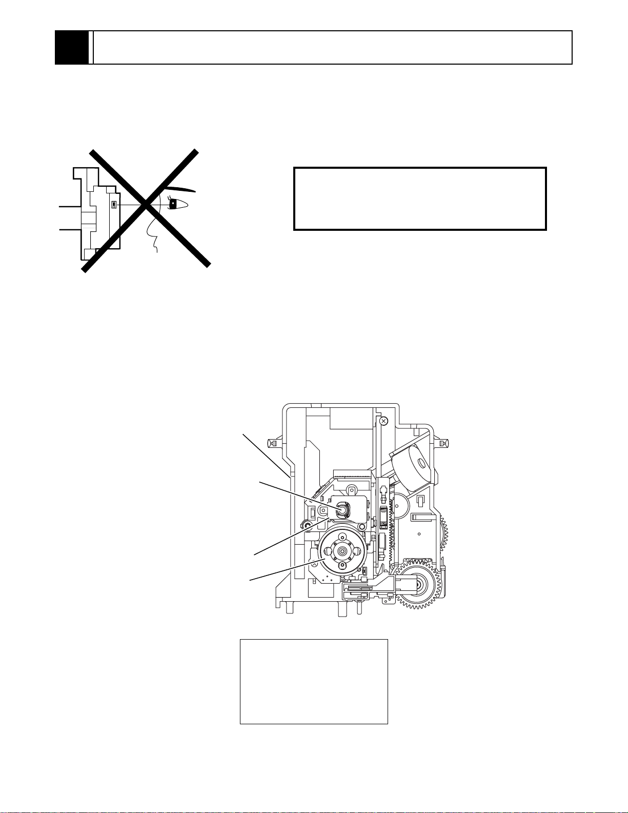
This DVD player uses a pickup that emits a laser beam.
Do not look directly at the l aser beam coming
from the pickup or allo w it t o str ike agai nst your
skin.
The laser beam is emitted from the location shown in the figure. When checking the laser diode, be sure to keep
your eyes at least 30cm away from the pickup lens when the diode is turned on. Do not look directly at the laser
beam.
Caution: Use of controls and adjustments, or doing procedures other than those specified herein, may result in
hazardous radiation exposure.
Drive Mecha Assembly
Laser Beam Radiation
Laser Pickup
Turntable
CAUTION
LASER RADIATION
WHEN OPEN. DO NOT
STARE INTO BEAM.
Location: Top of DVD mechanism.
1-1

1-2 IMPORTANT SAFETY PRECAUTIONS
1-2-1 Product Safety Notice
Some electrical and mechanical parts have special
safety-related characteristics which are often not evident from visual inspection, nor can the protection they
give necessarily be obtained by replacing them with
components rated for higher voltage, wattage, etc.
Parts that have special safety characteristics are identified by a # on schematics and in parts lists. Use of a
substitute replacement that does not have the same
safety characteristics as the recommended replacement part might create shock, fire, and/or other hazards. The Product’s Safety is under review
continuously and new instructions are issued whenever appropriate. Prior to shipment from the factory,
our products are carefully inspected to confirm with
the recognized product safety and electrical codes of
the countries in which they are to be sold. However, in
order to maintain such compliance, it is equally important to implement the following precautions when a set
is being serviced.
1-2-2 Precautions during Servicing
A. Parts identified by the # symbol are critical for
safety. Replace only with part number specified.
B. In addition to safety, other parts and assemblies
are specified for conformance with regulations
applying to spurious radiation. These must also be
replaced only with specified replacements.
Examples: RF converters, RF cables, noise blocking capacitors, and noise blocking filters, etc.
C. Use specified internal wiring. Note especially:
1)Wires covered with PVC tubing
2)Double insulated wires
3)High voltage leads
D. Use specified insulating materials for hazardous
live parts. Note especially:
1)Insulation tape
2)PVC tubing
3)Spacers
4)Insulators for transistors
E. When replacing AC primary side components
(transformers, power cord, etc.), wrap ends of
wires securely about the terminals before soldering.
F. Observe that the wires do not contact heat produc-
ing parts (heatsinks, oxide metal film resistors, fusible resistors, etc.).
G. Check that replaced wires do not contact sharp
edges or pointed parts.
H. When a power cord has been replaced, check that
5 - 6 kg of force in any direction will not loosen it.
I. Also check areas surrounding repaired locations.
J. Be careful that foreign objects (screws, solder
droplets, etc.) do not remain inside the set.
K. Crimp type wire connector
The power transformer uses crimp type connectors
which connect the power cord and the primary side
of the transformer. When replacing the transformer,
follow these steps carefully and precisely to prevent
shock hazards.
Replacement procedure
1)Remove the old connector by cutting the wires at a
point close to the connector.
Important: Do not re-use a connector. (Discard it.)
2)Strip about 15 mm of the insulation from the ends
of the wires. If the wires are stranded, twist the
strands to avoid frayed conductors.
3)Align the lengths of the wires to be connected.
Insert the wires fully into the connector.
4)Use a crimping tool to crimp the metal sleeve at its
center. Be sure to crimp fully to the complete closure of the tool.
L. When connecting or disconnecting the internal
connectors, first, disconnect the AC plug from the
AC outlet.
1-2
1-2-3 Safety Check after Servicing
Examine the area surrounding the repaired location for
damage or deterioration. Observe that screws, parts,
and wires have been returned to their original positions. Afterwards, do the following tests and confirm
the specified values to verify compliance with safety
standards.
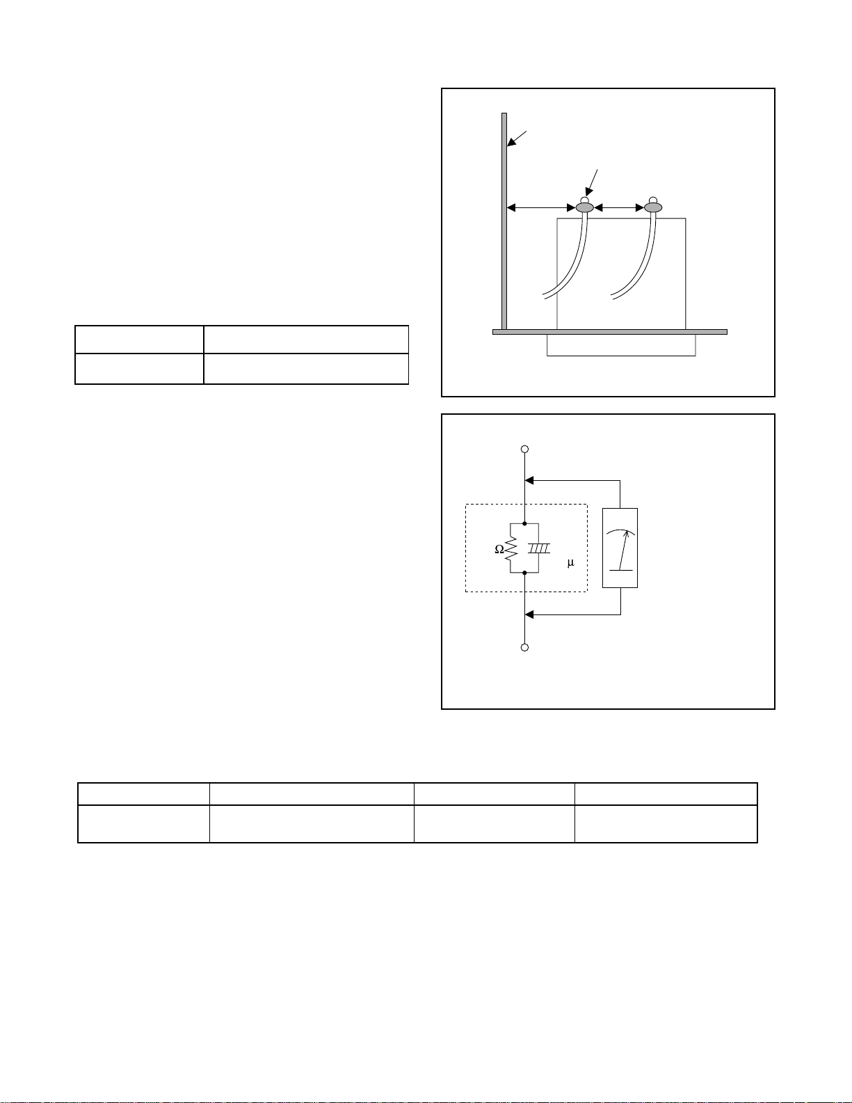
1. Clearance Distance
When replacing primary circuit components, confirm
specified clearance distance (d) and (d’) between soldered terminals, and between terminals and surrounding metallic parts. (See Fig. 1)
Table 1 : Ratings for selected area
AC Line Voltage Clearance Distance (d) (d’)
Chassis or Secondary Conductor
Primary Circuit Terminals
dd'
120 V
Note: This table is unofficial and for reference only.
Be sure to confirm the precise values.
2. Leakage Current Test
Confirm the specified (or lower) leakage current
between B (earth ground, power cord plug prongs)
and externally exposed accessible parts (RF terminals, antenna terminals, video and audio input and
output terminals, microphone jacks, earphone jacks,
etc.) is lower than or equal to the specified value in the
table below.
Measuring Method (Power ON) :
Insert load Z between B (earth ground, power cord
plug prongs) and exposed accessible parts. Use an
AC voltmeter to measure across the terminals of load
Z. See Fig. 2 and the following table.
Table 2: Leakage current ratings for selected areas
AC Line Voltage Load Z Leakage Current (i) Earth Ground (B) to:
120 V
≥ 3.2mm (0.126 inches)
0.15µF CAP. & 1.5kΩ RES.
Connected in parallel
Exposed Accessible Part
Z
1.5k
i≤0.5mA Peak Exposed accessible parts
0.15 F
Earth Ground
B
Power Cord Plug Prongs
AC Voltmeter
(High Impedance)
Fig. 1
Fig. 2
Note: This table is unofficial and for reference only. Be sure to confirm the precise values.
1-3
1-3 STANDARD NOTES FOR SERVICING
1-3-1 Circuit Board Indications
a. The output pin of the 3 pin Regulator ICs is indi-
cated as shown.
Top View
Out
b. For other ICs, pin 1 and every fifth pin are indicated
as shown.
Pin 1
c. The 1st pin of every male connector is indicated as
shown.
Input
In
Bottom View
5
10
1-3-3 Pb (Lead) Free Solder
When soldering, be sure to use the Pb free solder.
1-3-4 How to Remove / Install Flat
Pack-IC
1. Removal
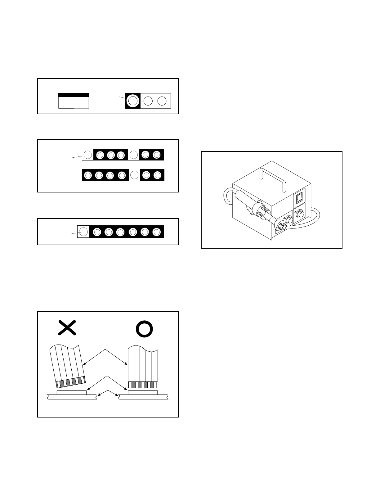
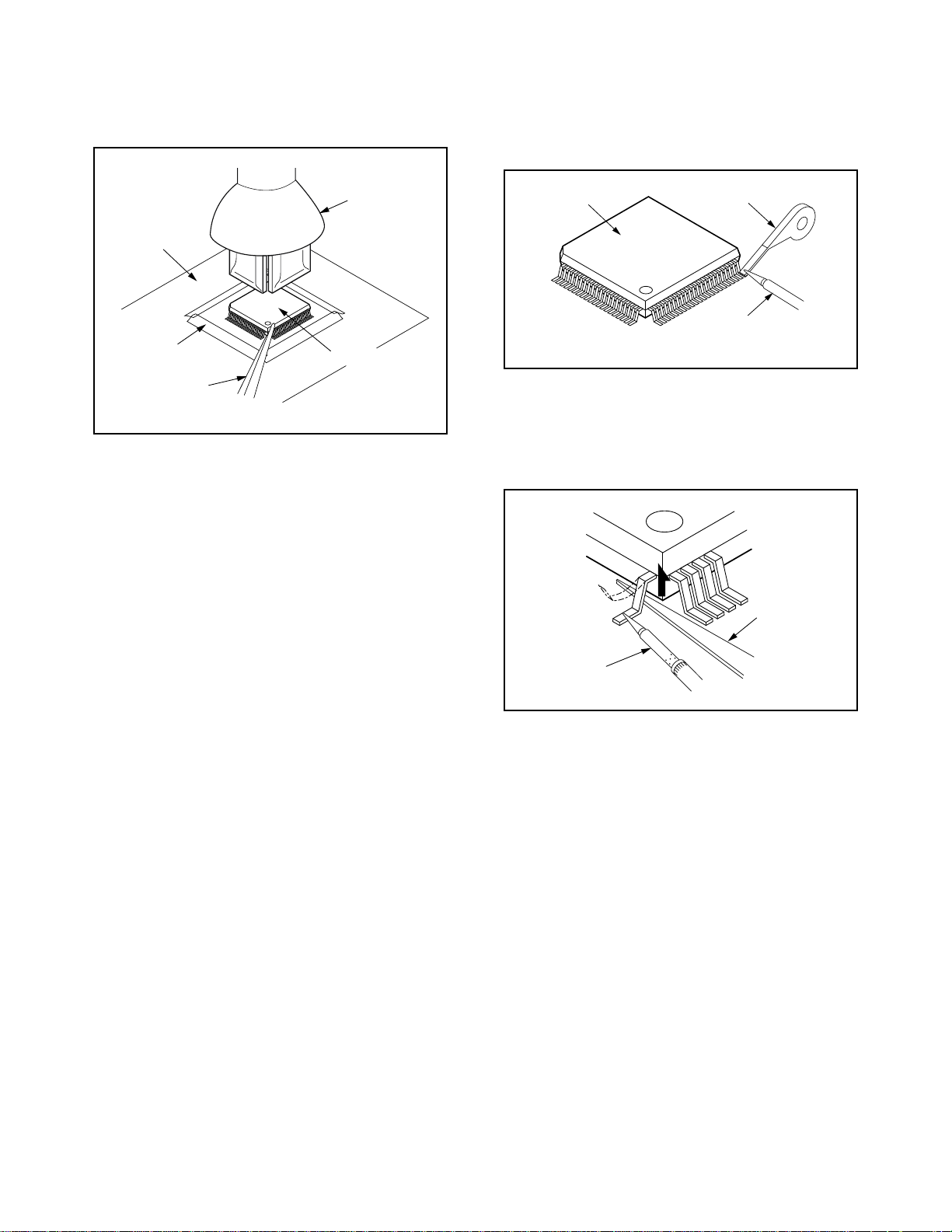
With Hot-Air Flat Pack-IC Desoldering Machine:
(1) Prepare the hot-air flat pack-IC desoldering
machine, then apply hot air to the Flat Pack-IC
(about 5 to 6 seconds). (Fig. S-1-1)
Pin 1
1-3-2 Instructions for Connectors
1. When you connect or disconnect the FFC (Flexible
Foil Connector) cable, be sure to first disconnect
the AC cord.
2. FFC (Flexible Foil Connector) cable should be
inserted parallel into the connector, not at an angle.
FFC Cable
Connector
CBA
* Be careful to avoid a short circuit.
Fig. S-1-1
(2) Remove the flat pack-IC with tweezers while apply-
ing the hot air.
(3) Bottom of the flat pack-IC is fixed with glue to the
CBA; when removing entire flat pack-IC, first apply
soldering iron to center of the flat pack-IC and heat
up. Then remove (glue will be melted). (Fig. S-1-6)
(1) Release the flat pack-IC from the CBA using twee-
zers. (Fig. S-1-6)
Caution:
1. The Flat Pack-IC shape may differ by models. Use
an appropriate hot-air flat pack-IC desoldering
machine, whose shape matches that of the Flat
Pack-IC.
2. Do not supply hot air to the chip parts around the
flat pack-IC for over 6 seconds because damage to
the chip parts may occur. Put masking tape around
the flat pack-IC to protect other parts from damage.
(Fig. S-1-2)
1-4
3. The flat pack-IC on the CBA is affixed with glue, so
be careful not to break or damage the foil of each
pin or the solder lands under the IC when removing
it.
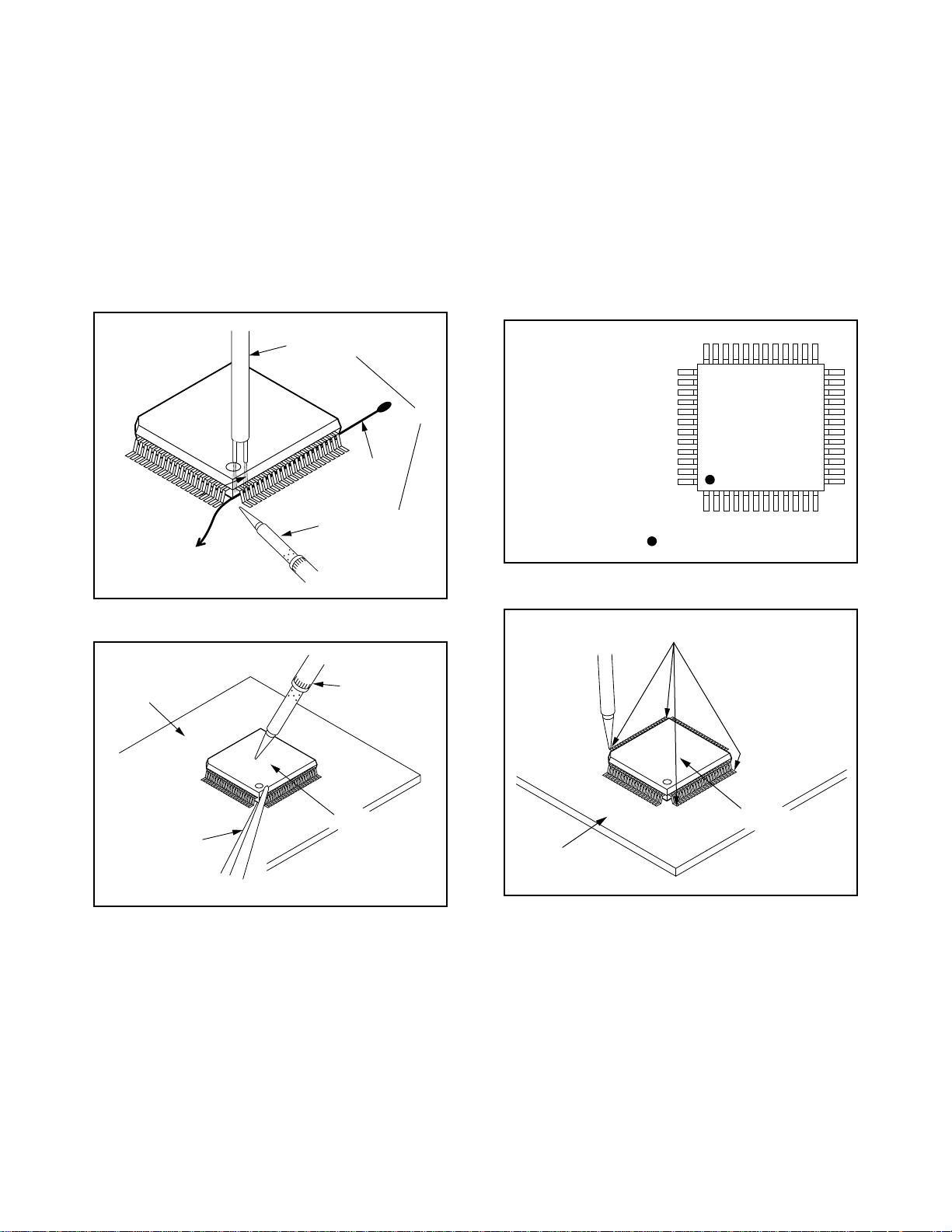
With Soldering Iron:
(1) Using desoldering braid, remove the solder from all
pins of the flat pack-IC. When you use solder flux
which is applied to all pins of the flat pack-IC, you
can remove it easily. (Fig. S-1-3)
CBA
Masking
Tape
Tweezers
Hot-air
Flat Pack-IC
Desoldering
Machine
Flat Pack-IC
Fig. S-1-2
Flat Pack-IC
Desoldering Braid
Soldering Iron
Fig. S-1-3
(2) Lift each lead of the flat pack-IC upward one by
one, using a sharp pin or wire to which solder will
not adhere (iron wire). When heating the pins, use
a fine tip soldering iron or a hot air desoldering
machine. (Fig. S-1-4)
Sharp
Pin
Fine Tip
Soldering Iron
(3) Bottom of the flat pack-IC is fixed with glue to the
CBA; when removing entire flat pack-IC, first apply
soldering iron to center of the flat pack-IC and heat
up. Then remove (glue will be melted). (Fig. S-1-6)
(4) Release the flat pack-IC from the CBA using twee-
zers. (Fig. S-1-6)
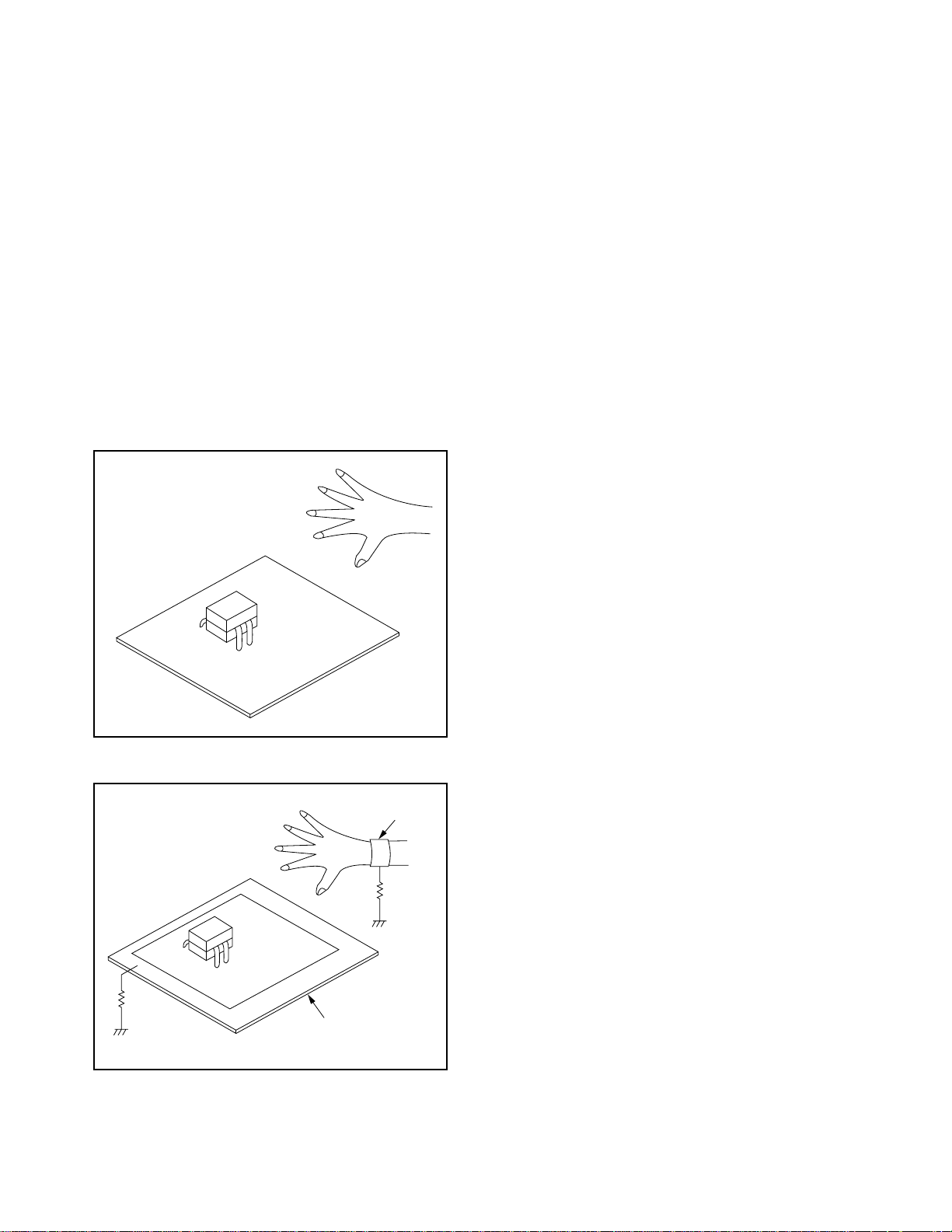
With Iron Wire:
(1) Using desoldering braid, remove the solder from all
pins of the flat pack-IC. When you use solder flux
which is applied to all pins of the flat pack-IC, you
can remove it easily. (Fig. S-1-3)
(2) Affix the wire to a workbench or solid mounting
point, as shown in Fig. S-1-5.
(3) While heating the pins using a fine tip soldering
iron or hot air blower, pull up the wire as the solder
melts so as to lift the IC leads from the CBA contact
pads as shown in Fig. S-1-5
Fig. S-1-4
1-5
(4) Bottom of the flat pack-IC is fixed with glue to the
CBA; when removing entire flat pack-IC, first apply
soldering iron to center of the flat pack-IC and heat
up. Then remove (glue will be melted). (Fig. S-1-6)
(5) Release the flat pack-IC from the CBA using twee-
zers. (Fig. S-1-6)
Note:
When using a soldering iron, care must be taken
to ensure that the flat pack-IC is not being held by
glue. When the flat pack-IC is removed from the
CBA, handle it gently because it may be damaged
if force is applied.
2. Installation
(1) Using desoldering braid, remove the solder from
the foil of each pin of the flat pack-IC on the CBA so
you can install a replacement flat pack-IC more
easily.
(2) The “I” mark on the flat pack-IC indicates pin 1.
(See Fig. S-1-7.) Be sure this mark matches the 1
on the PCB when positioning for installation. Then
presolder the four corners of the flat pack-IC. (See
Fig. S-1-8.)
(3) Solder all pins of the flat pack-IC. Be sure that none
of the pins have solder bridges.
To Solid
Mounting Point
CBA
Hot Air Blower
Iron Wire
Soldering Iron
Fig. S-1-5
Fine Tip
Soldering Iron
or
Example :
Pin 1 of the Flat Pack-IC
is indicated by a " " mark.
Presolder
Fig. S-1-7
Tweezers
Flat Pack-IC
Fig. S-1-6
Flat Pack-IC
CBA
Fig. S-1-8
1-6
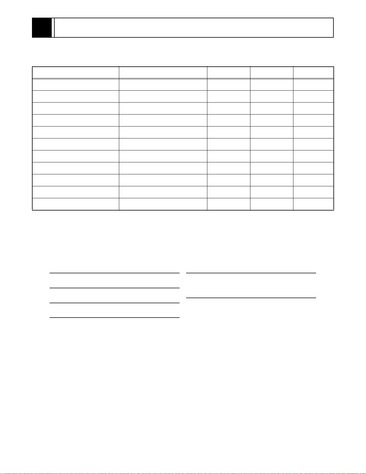
1-3-5 Instructions for Handling
Semi-conductors
Electrostatic breakdown of the semi-conductors may
occur due to a potential difference caused by electrostatic charge during unpacking or repair work.
1. Ground for Human Body
Be sure to wear a grounding band (1MΩ) that is properly grounded to remove any static electricity that may
be charged on the body.
2. Ground for Workbench
(4) Be sure to place a conductive sheet or copper plate
with proper grounding (1MΩ) on the workbench or
other surface, where the semi-conductors are to be
placed. Because the static electricity charge on
clothing will not escape through the body grounding band, be careful to avoid contacting semi-conductors with your clothing.
<Incorrect>
<Correct>
1MΩ
CBA
Grounding Band
1MΩ
CBA
Conductive Sheet or
Copper Plate
1-7
2
GENERAL INFORMATION
2-1 SPECIFICATIONS
ITEM CONDITIONS UNIT NOMINAL LIMIT
1. Video Output 75 ohm load Vpp 1.0 ± 0.1
2. Optical Digital Out dBm -18
3. Audio (PCM)
3-1. Output Level 1 kHz 0 dB Vrms 2.0
3-2. S/N dB 120
3-3. Freq. Response
DVD fs = 48 kHz 20~22 kHz dB ± 0.5
CD fs = 44.1 kHz 20~20 kHz dB ± 0.5
3-4. THD+N
DVD 1 kHz 0dB % 0.004
CD 1 kHz 0dB % 0.0045
NOTES:
1. All Items are measured without pre-emphasis unless otherwise specified.
2. Power supply : AC120 V 60 Hz
3. Load imp. : 100 k ohm
4. Room ambient : + 25
OUTPUT SIGNAL FORMAT
NTSC color
POWER SOURCE
120 V AC +/- 10%, 60 Hz +/- 0.5%
POWER CONSUMPTION
10 W (standby: 0.8W)
OPERATING TEMPERATURE
41˚F(5˚C) to 104˚F(40˚C)
°C
DIMENSIONS
W 17-1/8” (435 mm)
H 2” (51 mm)
D 8-5/16” (211 mm)
WEIGHT
Approx 2.9 lbs (1.3 kg)
2-1

2-2 COMPARISON OF MODELS
←: Same as on left
ITEM
Dimensional 435(W) x 50(H) x 211(D) mm 435(W) x 55(H) x 211(D) mm
Hot Stamp --- ←
Ultra Vision Badge --- ←
APPEARANCEGENERALVIDEOAUDIO
Drive Speed 1x ←
Laser 2 ←
DVD/VCD/SVCD/CD-DA O / --- / --- / O ←
CD-R/CD-RW/DVD-R (Video Format) O / O / O ←
DVD-RAM/DVD-RW --- / O (Video Mode) --- / --MP3/WMA O / --- ←
OSD languages 3 (English, French, Spanish) ←
Jog Shuttle on Front --- ←
Headphone Jack / Volume --- / --- ←
PAL Disc NTSC Out --- ←
Video Out Mode NTSC/PAL/PAL60 O / --- / --- ←
S-Video / Component / Composite O / O / O ←
Video D/A Converter 10bit / 54MHz ←
Black Level Select O ←
Picture Control --- ←
Progressive Out O ←
Audio D/A Converter 192kHz / 24bit ←
Digital Audio Out Optical / Coaxial --- / O ←
Dolby Digital 5.1 ch Decode --- ←
DTS Digital Out O --Virtual Surround O ←
Dynamic Range Compression (Dolby
Digital)
DVD Audio --- ←
Search Speed
Slow Speed 1/16, 1/8, 1/2 (FORWARD/REWIND) ←
IP Search (Smooth 2x Play) O ←
1.5x Play with Audio --- ←
TRICK PLAY
Step Forward / Reverse O / --- ←
Still Picture Select (Frame/Field) Frame / Field / Auto Auto Only
DV-P745U/P745U(C) DV-P735U/P735U(C)/P533U
O ←
2 to 100 (FORWARD/REWIND)
(DVD: 2, 8, 50, 100/CD: 16)
←
2-2

ITEM
Disc Navigation O
DVD Zoom x2 / x4 / x16 O / O / --- ←
Program and Random Play of DVD /
VCD
A-B Repeat O ←
Repeat O ←
Resume O O (can not effect after Power off)
FEATURES
Closed Caption for NTSC DVD O ←
Front Panel Display Dimmer O ←
Screen Saver O ←
Auto Power Off O (always on) O
Jog Shuttle on Remote --- ←
DV-P745U/P745U(C) DV-P735U/P735U(C)/P533U
O (DV-P735U/P735U(C))
--- (DV-P533U)
--- ←
REMOTE
TV Control ---
CONTROLLER
O (DV-P735U/P735U(C))
--- (DV-P533U)
2-3

2-3 OPERATING CONTROLS AND FUNCTIONS
FRONT PANEL
1 2 3 4 5 6 7 8
REAR VIEW
9
10 12 13 1411
1. y/I (POWER/STANDBY)
Switch the player to ON or OFF.
(As to the indication of the Operate switch, “I” indicates
ON and “y” indicates electrical power STANDBY.)
2. SKIP/FR
Go to previous chapter or track during playback;
Press and hold for 1.5 seconds for a reverse search.
3. PLAY
Start or resume disc playback.
Press to switch progressive scanning mode and
interlace mode.
4. FF/SKIP
Go to next chapter or track during playback;
Press and hold for 1.5 seconds for a forward search.
5. STOP
Stop playback.
6. OPEN/CLOSE
Open/close the disc tray.
7. Disc tray
8. Display
9. MAIN (AC Power Cord)
Connect to a standard AC outlet.
10. COAXIAL (Digital audio out)
Use coaxial digital audio out to connect to a compatible
Dolby Digital receiver. Use to connect to a Dolby Digital
decoder or DTS decoder.
11. AUDIO OUT (Left/Right)
Connect to the AUDIO inputs of an amplifier, receiver or
stereo system.
12. VIDEO OUT
Use a video cable to connect one of the jack to Video
input on your A/V-compatible TV, wide screen TV, or
Stereo system.
13.COMPONENT VIDEO OUT
Connect to a TV with the Component video in jacks.
14. S-VIDEO OUT
Use the S-Video cable to connect this jack to the SVideo jack on your A/V-compatible TV or wide screen
TV for a higher quality picture.
Caution: Do not touch the inner pins of the jacks on the
rear panel. Electrostatic discharge may cause permanent
damage to the player.
2-4
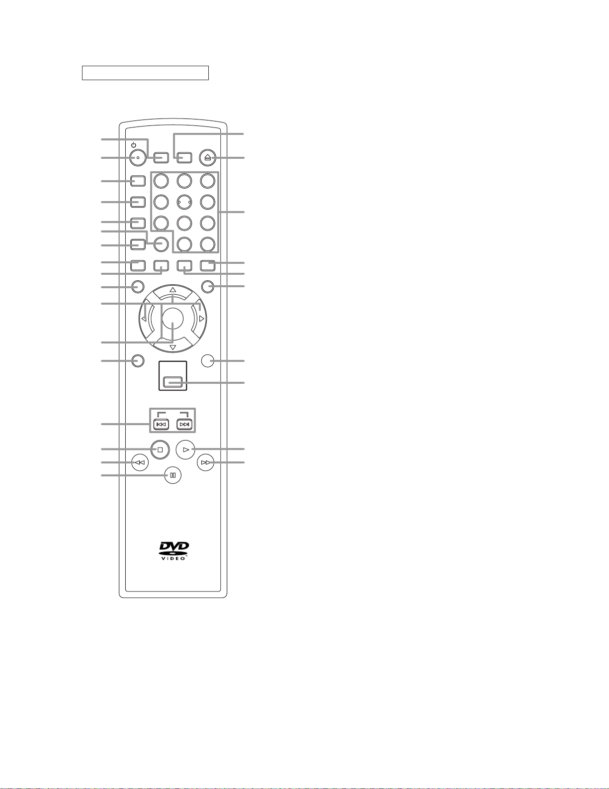
REMOTE CONTROL
y
y
B
o
E
D
1
/ I
2
A-B REPEAT
3
REPEAT
4
5
MODE
6
ZOOM
7
8
9
ANGLE
MENU
10
11
12
RETURN
13
14
15
16
17
SEARCH
MODE
SURROUND
45
7
CLEAR
AUDIO
SUBTITLE
ENTER
DISC
NAVIGATION
SKIP
PLAY
STOP
PAUSE /STEP
HITACHI
DV-RM745U
OPEN /
CLOSE
213
6
89
0
+10
DISPLAY
TOP MENU
SETUP
27
26
25
24
23
22
21
20
19
18
1. SURROUND
Press to activate the virtual sound.
y
2.
/I
(POWER/STANDBY)
Press to turn the power on and off.
(As to the indication of the Operate switch, "I" shows
ON and "
3. A-B REPEAT
Repeats playback of a selected section.
4. REPEAT
Repeats playback of the current disc, title, chapter or
track.
5. MODE
Activates program playback or random playback mode
when playing CDs or MP3. Sets Black level and virtual
surround.
6. ZOOM
Enlarges part of a DVD-reproduced image.
7. CLEAR
Press to reset the setting.
8. ANGLE
Press to change the camera angle to see the sequence
being played back from a different angle.
9. SUBTITLE
Press to select the desired subtitle language.
10. MENU
Press to display the menu of the Disc.
11. Arrow Buttons (
Move the cursor and determines its position.
12. ENTER
Press to accept a setting.
13. RETURN
Returns to the previous operation.
14. SKIP
Press to skip Chapters or Tracks.
15. STOP
Press to stop the disc motion.
E
16.
Press to view the DVD picture in fast reverse motion or
to reverse playback of an Audio CD.
17. PAUSE/STEP
Press to pause Disc playback. Press repeatedly to
advance the DVD picture step by step or one frame at a
time.
D
18.
Press to fast forward the Disc. Press PAUSE/STEP,
then press this button to begin slow motion playback.
Press this button repeatedly to change the forward
speed of slow motion.
19. PLAY
Press to begin playback.
20. DISC NAVIGATION
Press to display the first scenes of each chapter of the
title being played.
21. SETUP
Press to enter the setup mode.
22. TOP MENU
Press to call up the title menu.
23. AUDIO
Press to select a desired audio language or sound
mode.
24. DISPLAY
Press to access or remove the display screen during
DVD or Audio CD playback.
25. Numerical Buttons
Press to directly select a Track (Audio CD and MP3) for
playback.
26. OPEN/CLOSE
Press to open or close the disc loading tray.
27. SEARCH MODE
Press to access or remove the Search display, which
allows you to go directly to a specific
Title/Chapter/Track/Time.
y
" shows electrical power stand-by.)
ppo
ssB
)
2-5
2-4 COMPARISON OF MAIN CONTROL ICS
←: Same as on left
ITEM DV-P745U/P745U(C) DV-P735U/P735U(C)/P533U
SW NC7SB3157P6X / SN74LVC1G3157DCKR
(IC201)
OP AMP LM324PWR / LM324PT (IC202) KIA324F-EL (IC202)
SERVO DRIVE SA5694 / FAN8024CDTF / BA5954FP-E2 /
BA5888FP-E2 (IC301)
RESET PST3229NR (IC461) PST9127NR / BMR-110527 (IC461)
BMR-110529 (IC462) ----------
MICRO CONTROLLER MN35202 (IC101) MN35102 (IC101)
SDRAM K4S641632H-UC75 (IC503) K4S643232F-TC60 / HY57V643220CT-
FLASH ROM MBM29LB160T / BM90TN-K /
MX29LV160ABTC-90G (IC103)
LATCH ---------- 74LVX573MTCX / TC74LVX573FT(EL)
CLOCK GENERATOR ---------- BU2363FV-E2 (IC451)
AUDIO D/A CONVERTER PCM1755DBQR (IC601) PCM1751DBQR (IC601)
ERROR VOLTAGE DET LTV-817B-F / LTV-817C-F / PS2561A-1(W) /
PS2561A-1(Q) (IC1001)
1.2V REG PQ070XZ5MZP (IC1002) PQ070XF01SZ (IC1002)
SHUNT REGULATOR KIA431-AT / FAN431AZXA (IC1006) KIA431-AT (IC1006)
AMP KIA4558P / NJM4558D (IC1201) ← (IC1201)
VIDEO DRIVER MM1637XVBE (IC1402) MM1622XJBE (IC1402)
MM1636XWRE (IC1403) ----------
FRONT PANEL CONTROL PT6313-S-TP / SC16313 (IC2001) PT6313-S-TP (IC2001)
NC7SB3157P6X (IC201)
SA5694 / BA5954FP-E2 (IC301)
(7,55) (IC102)
MBM29LV160BE90TN-K /
MBM29LV160B90PFTNSFK /
HY29LV160BT-90 / MX29LV160BTC-90 /
M29W160DB70N6 (IC103)
(IC104, IC105)
LTV-817B-F / LTV-817C-F (IC1001)
2-6

2-5
LIST OF ABBREVIATIONS AND TERMS FOR DVD PLAYER
Index Abbreviation/Term Explanation
A AC3 See Dolby AC3.
C CD-R One type of DVD standard disc, to which writing once is possible (recordable type)
CD-RW One type of CD standard disc, to which writing up to 1000 times is possible
Component video
output terminals
D Dolby AC3 Audio coding format developed by Dolby Laboratories in U.S, also simply referred to as AC3
D terminal This terminal, specified by EIAJ (currently JEITA), can automatically switch "digital hi-vision"
DTS Digital Theater System: Sound system as for movie theaters developed by US Digital Theater
DVD Digital Versatile Disc. A huge amount of digital data for video (movie) and audio can be
DVD-Audio One type of DVD standard disc, on which high-quality audio can be recorded
DVD-R One type of DVD standard disc, to which writing once is possible (recordable type)
DVD-RAM One type of DVD standard disc, to which writing up to 100,000 times is possible
DVD-ROM One type of DVD standard disc, to which data for computer can be recorded
DVD-RW One type of DVD standard disc, to which writing up to 1000 times is possible
DVD-Video One type of DVD standard disc, on which high-quality video and audio can be recorded
DVD Video Format Video recording/playback standard that applies to DVD-Video, DVD-R and DVD-RW
DVD Video Recording
Format
DVD Forum International organization that formulates the technical standards of DVD
E EIAJ Electronic Industries Association of Japan: An organization of manufacturers of consumer
J JPEG Joint Photographic Expert Group: International standard format for compressing still images.
L Linear PCM Linear Pulse Code Modulation: LPCM is a format that digitizes analog audio signal during
M MPEG Moving Picture Experts Group: Standard related to compression of digital video and audio.
MPEG Audio Layer 2 One of three audio compression standards (layers 1-3) defined by MPEG
MP3 MPEG1 Audio Layer-3: Audio data digital compression technology.
P Progressive playback
function
S SDMI Secure Digital Music Initiative: This conference was established by hardware makers, the
V Virtual surround This technology localizes sound at any position using only two front speakers, by subjecting
Used for outputs of HDTV video signal format. Since signals for brightness and colors are
independently handled for components signals (Y: luminance signal; PR/PB: chrominance
signals), degrading of image will be reduced.
format: Supports 5-channel full-range sound and one channel for sub-woofer sound
playback.
programs of BS digital broadcast, and "digital standard broadcast" of current image quality. A
tuner and TV can easily be connected to the D terminal. There are 5 types of D terminal,
depending on the different format of video signal passing thorough the D terminal.
Systems, Inc. The number of channels provided by DTS is the same for Dolby AC3.
recorded on this disc, whose size is the same as CD.
Video recording/playback standard that applies to DVD-RAM and DVD-RW: This allows
versatile editing functions, differing from the DVD Video Format.
electronic devices, industrial electronic devices and electronic components, established in
April 1948. EIAJ merged with JEIDA (Japan Electronic Industry Development Association) in
November 2000 to become JEITA (Japan Electronics and Information Technology Industries
Association).
recording and converts it back to analog signal during playback.
MPEG2 is a higher standard of MPEG and is applied to video (movie) requiring higher
quality.
This function converts interlaced images to non-interlaced images and displays them. It can
play back 24-frame/second images included in DVD movie software, etc.
Recording Industry Association of America (RIAA) and music industry companies, to protect
copyrights of musical compositions.
the L and R signals to matrix operation. It uses the four transfer functions from L/R speakers
located at specified positions to both ears of listener located in a specified position, taking
into account the shape of head and the effect of earlobes, and the two transfer functions from
any position to both ears.
2-7