

Hitachi DVP-735-U, DVP-533-U Service Manual
TK No. 9301E
DV-P735U
SERVICE MANUAL
DV-P735U(C)
DV-P533U
SPECIFICATIONS AND PARTS ARE SUBJECT TO CHANGE FOR IMPROVEMENT
DVD PLAYER
2003 Digital Media Division, TokaiFebruary

CONTENTS
1 CAUTIONS FOR SAFETY IN PERFORMING
REPAIR . . . . . . . . . . . . . . . . . . . . . . . . . . . . . . . .1-1
1-1 LASER BEAM SAFETY PRECAUTIONS . . . . . . . . 1-1
1-2 IMPORTANT SAFETY PRECAUTIONS . . . . . . . . . 1-2
1-2-1 Product Safety Notice . . . . . . . . . . . . . . . . . . . . . 1-2
1-2-2 Precautions during Servicing . . . . . . . . . . . . . . . 1-2
1-2-3 Safety Check after Servicing . . . . . . . . . . . . . . . . 1-3
1-3 STANDARD NOTES FOR SERVICING . . . . . . . . . . 1-4
1-3-1 Circuit Board Indications . . . . . . . . . . . . . . . . . . . 1-4
1-3-2 Instructions for Connectors . . . . . . . . . . . . . . . . . 1-4
1-3-3 How to Remove/Install Flat Pack-IC . . . . . . . . . . 1-4
1-3-4 Instructions for Handling Semi-conductors . . . . . 1-6
2 GENERAL INFORMATION . . . . . . . . . . . . . . . . .2-1
2-1 SPECIFICATIONS . . . . . . . . . . . . . . . . . . . . . . . . . . 2-1
2-2 COMPARISON OF MODELS. . . . . . . . . . . . . . . . . . 2-2
2-3 OPERATING CONTROLS AND FUNCTIONS. . . . . 2-4
3 MAINTENANCE AND INSPECTION. . . . . . . . . .3-1
3-1 TROUBLESHOOTING . . . . . . . . . . . . . . . . . . . . . . . 3-1
3-2 FIRMWARE RENEWAL MODE . . . . . . . . . . . . . . . . 3-7
3-2-1 How to Update the Firmware Version . . . . . . . . . 3-7
3-2-2 How to Verify the Firmware Version . . . . . . . . . . 3-8
SCHEMATIC AND BLOCK DIAGRAMS/CBA'S
1 SCHEMATIC DIAGRAMS/CBA’S AND TEST POINTS . 1
2 WIRING DIAGRAM . . . . . . . . . . . . . . . . . . . . . . . . . . . . . 3
3 SCHEMATIC DIAGRAMS . . . . . . . . . . . . . . . . . . . . . . . . 4
3-1 DVD Main 1/3 Schematic Diagram . . . . . . . . . . . . . . . 4
3-2 DVD Main 2/3 Schematic Diagram . . . . . . . . . . . . . . . 5
3-3 DVD Main 3/3 Schematic Diagram . . . . . . . . . . . . . . . 7
3-4 AV 1/3 Schematic Diagram . . . . . . . . . . . . . . . . . . . . . 8
3-5 AV 2/3 Schematic Diagram . . . . . . . . . . . . . . . . . . . . . 9
3-6 AV 3/3 & Function Schematic Diagram . . . . . . . . . . . 10
4 WAVEFORMS . . . . . . . . . . . . . . . . . . . . . . . . . . . . . . . . 11
5 CIRCUIT BOARD DIAGRAMS . . . . . . . . . . . . . . . . . . . 12
5-1 AV CBA Top View . . . . . . . . . . . . . . . . . . . . . . . . . . . 12
5-2 AV CBA Bottom View. . . . . . . . . . . . . . . . . . . . . . . . . 13
5-3 Function CBA Top/Bottom View . . . . . . . . . . . . . . . . 14
6 BLOCK DIAGRAMS . . . . . . . . . . . . . . . . . . . . . . . . . . . 15
6-1 System Control/Servo Block Diagram . . . . . . . . . . . . 15
6-2 Digital Signal Process Block Diagram . . . . . . . . . . . . 16
6-3 Video/Audio Block Diagram . . . . . . . . . . . . . . . . . . . . 17
6-4 Power Supply Block Diagram. . . . . . . . . . . . . . . . . . . 18
7 SYSTEM CONTROL TIMING CHARTS . . . . . . . . . . . . 19
8 IC PIN FUNCTION DESCRIPTIONS . . . . . . . . . . . . . . 20
9 LEAD IDENTIFICATIONS . . . . . . . . . . . . . . . . . . . . . . . 21
4 DISASSEMBLY . . . . . . . . . . . . . . . . . . . . . . . . . .4-1
4-1 CABINET DISASSEMBLY INSTRUCTIONS . . . . . . 4-1
4-1-1 Disassembly Flowchart . . . . . . . . . . . . . . . . . . . . 4-1
4-1-2 Disassembly Method . . . . . . . . . . . . . . . . . . . . . . 4-1
5 EXPLODED VIEW AND PARTS LIST. . . . . . . . .5-1
5-1 EXPLODED VIEW . . . . . . . . . . . . . . . . . . . . . . . . . . 5-1
5-2 REPLACEMENT PARTS LIST. . . . . . . . . . . . . . . . . 5-2
5-2-1 Mechanical Parts List . . . . . . . . . . . . . . . . . . . . . 5-2
5-2-2 Electrical Parts List . . . . . . . . . . . . . . . . . . . . . . . 5-3
1
CAUTION FOR SAFETY IN PERFORMING REPAIR
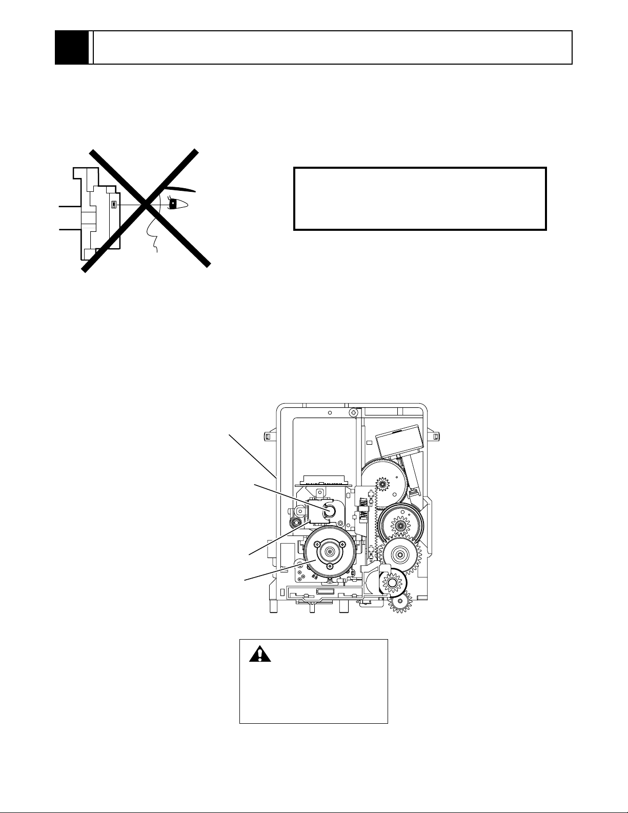
1-1 LASER BEAM SAFETY PRECAUTIONS
This DVD player uses a pickup that emits a laser beam.
Do not look directly at the laser beam coming
from the pickup or allow it to strike against your
skin.
The laser beam is emitted from the location shown in the figure. When checking the laser diode, be sure to keep
your eyes at least 30cm away from the pickup lens when the diode is turned on. Do not look directly at the laser
beam.
Caution: Use of controls and adjustments, or doing procedures other than those specified herein, may result in
hazardous radiation exposure.
Drive Mecha Assembly
Laser Beam Radiation
Laser Pickup
Turntable
CAUTION
LASER RADIATION
WHEN OPEN. DO NOT
STARE INTO BEAM.
Location: Inside Top of DVD mechanism.
1-1

1-2 IMPORTANT SAFETY PRECAUTIONS
1-2-1 Product Safety Notice
Some electrical and mechanical parts have special
safety-related characteristics which are often not evident from visual inspection, nor can the protection they
give necessarily be obtained by replacing them with
components rated for higher voltage, wattage, etc.
Parts that have special safety characteristics are identified by a # on schematics and in parts lists. Use of a
substitute replacement that does not have the same
safety characteristics as the recommended replacement part might create shock, fire, and/or other hazards. The Product’s Safety is under review
continuously and new instructions are issued whenever appropriate. Prior to shipment from the factory,
our products are carefully inspected to confirm with
the recognized product safety and electrical codes of
the countries in which they are to be sold. However, in
order to maintain such compliance, it is equally important to implement the following precautions when a set
is being serviced.
1-2-2 Precautions during Servicing
A. Parts identified by the # symbol are critical for
safety. Replace only with part number specified.
B. In addition to safety, other parts and assemblies
are specified for conformance with regulations
applying to spurious radiation. These must also be
replaced only with specified replacements.
Examples: RF converters, RF cables, noise blocking capacitors, and noise blocking filters, etc.
C. Use specified internal wiring. Note especially:
1)Wires covered with PVC tubing
2)Double insulated wires
3)High voltage leads
D. Use specified insulating materials for hazardous
live parts. Note especially:
1)Insulation tape
2)PVC tubing
3)Spacers
4)Insulators for transistors
E. When replacing AC primary side components
(transformers, power cord, etc.), wrap ends of
wires securely about the terminals before soldering.
F. Observe that the wires do not contact heat produc-
ing parts (heatsinks, oxide metal film resistors, fusible resistors, etc.).
G. Check that replaced wires do not contact sharp
edges or pointed parts.
H. When a power cord has been replaced, check that
5 - 6 kg of force in any direction will not loosen it.
I. Also check areas surrounding repaired locations.
J. Be careful that foreign objects (screws, solder
droplets, etc.) do not remain inside the set.
K. Crimp type wire connector
The power transformer uses crimp type connectors
which connect the power cord and the primary side
of the transformer. When replacing the transformer,
follow these steps carefully and precisely to prevent
shock hazards.
Replacement procedure
1)Remove the old connector by cutting the wires at a
point close to the connector.
Important: Do not re-use a connector. (Discard it.)
2)Strip about 15 mm of the insulation from the ends
of the wires. If the wires are stranded, twist the
strands to avoid frayed conductors.
3)Align the lengths of the wires to be connected.
Insert the wires fully into the connector.
4)Use a crimping tool to crimp the metal sleeve at its
center. Be sure to crimp fully to the complete closure of the tool.
L. When connecting or disconnecting the internal
connectors, first, disconnect the AC plug from the
AC outlet.
1-2
1-2-3 Safety Check after Servicing
Examine the area surrounding the repaired location for
damage or deterioration. Observe that screws, parts,
and wires have been returned to their original positions. Afterwards, do the following tests and confirm
the specified values to verify compliance with safety
standards.
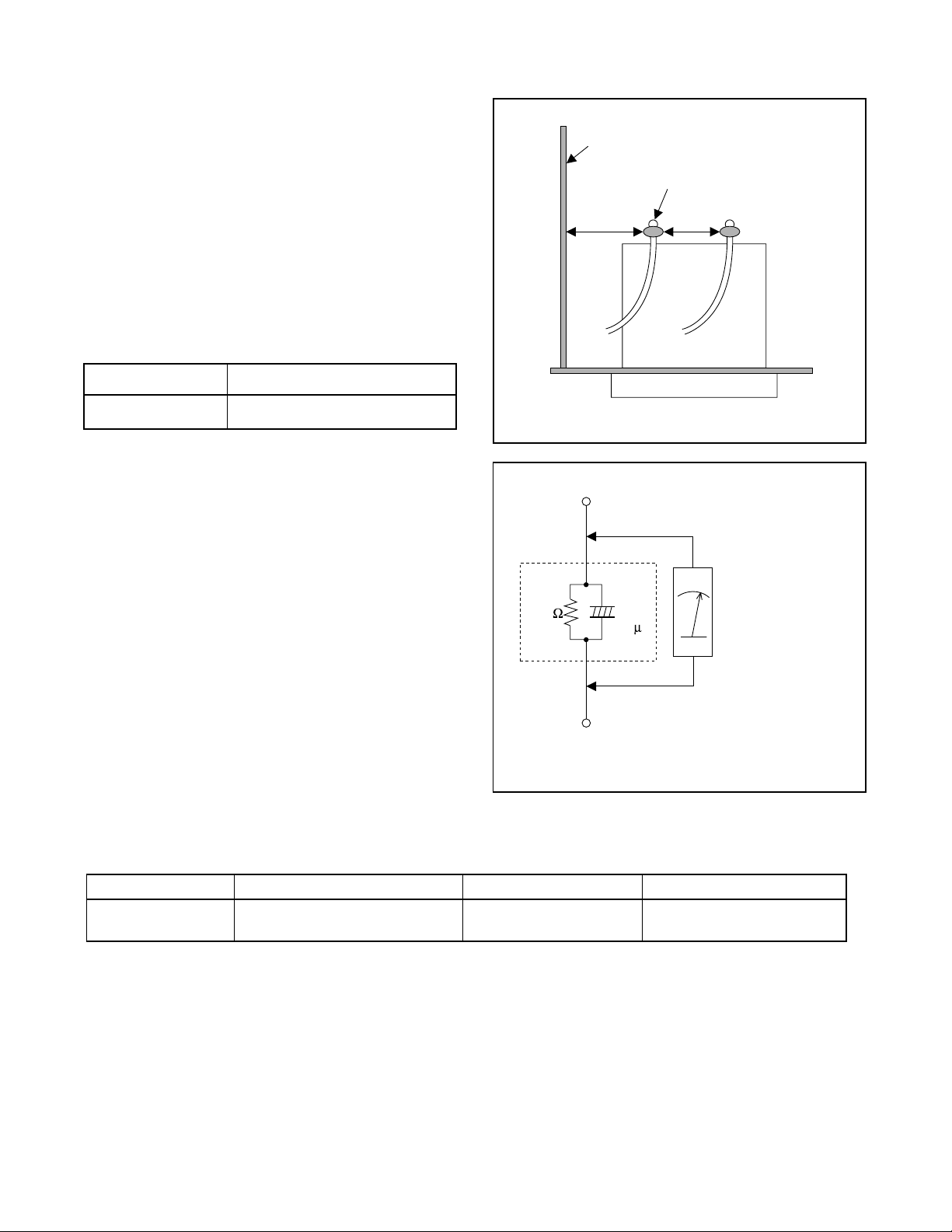
1. Clearance Distance
When replacing primary circuit components, confirm
specified clearance distance (d) and (d’) between soldered terminals, and between terminals and surrounding metallic parts. (See Fig. 1)
Table 1 : Ratings for selected area
AC Line Voltage Clearance Distance (d) (d’)
Chassis or Secondary Conductor
Primary Circuit Terminals
dd'
120 V
Note: This table is unofficial and for reference only.
Be sure to confirm the precise values.
2. Leakage Current Test
Confirm the specified (or lower) leakage current
between B (earth ground, power cord plug prongs)
and externally exposed accessible parts (RF terminals, antenna terminals, video and audio input and
output terminals, microphone jacks, earphone jacks,
etc.) is lower than or equal to the specified value in the
table below.
Measuring Method (Power ON) :
Insert load Z between B (earth ground, power cord
plug prongs) and exposed accessible parts. Use an
AC voltmeter to measure across the terminals of load
Z. See Fig. 2 and the following table.
Table 2: Leakage current ratings for selected areas
AC Line Voltage Load Z Leakage Current (i) Earth Ground (B) to:
120 V
≥ 3.2mm (0.126 inches)
0.15µF CAP. & 1.5kΩ RES.
Connected in parallel
Exposed Accessible Part
Z
1.5k
i≤0.5mA Peak Exposed accessible parts
0.15 F
Earth Ground
B
Power Cord Plug Prongs
AC Voltmeter
(High Impedance)
Fig. 1
Fig. 2
Note: This table is unofficial and for reference only. Be sure to confirm the precise values.
1-3
1-3 STANDARD NOTES FOR SERVICING
1-3-1 Circuit Board Indications
a. The output pin of the 3 pin Regulator ICs is indi-
cated as shown.
Top View
Input
Out
b. For other ICs, pin 1 and every fifth pin are indicated
as shown.
In
Pin 1
c. The 1st pin of every male connector is indicated as
shown.
Pin 1
Bottom View
5
10
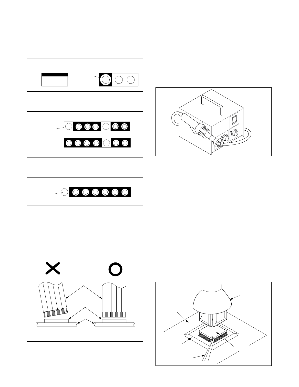
1-3-3 How to Remove / Install Flat
Pack-IC
1. Removal
With Hot-Air Flat Pack-IC Desoldering Machine:.
(1) Prepare the hot-air flat pack-IC desoldering
machine, then apply hot air to the Flat Pack-IC
(about 5 to 6 seconds). (Fig. S-1-1)
Fig. S-1-1
(2) Remove the flat pack-IC with tweezers while apply-
ing the hot air.
(3) Bottom of the flat pack-IC is fixed with glue to the
CBA; when removing entire flat pack-IC, first apply
soldering iron to center of the flat pack-IC and heat
up. Then remove (glue will be melted). (Fig. S-1-6)
(1) Release the flat pack-IC from the CBA using twee-
zers. (Fig. S-1-6)
1-3-2 Instructions for Connectors
1. When you connect or disconnect the FFC (Flexible
Foil Connector) cable, be sure to first disconnect
the AC cord.
2. FFC (Flexible Foil Connector) cable should be
inserted parallel into the connector, not at an angle.
FFC Cable
Connector
CBA
* Be careful to avoid a short circuit.
Caution:
1. Do not supply hot air to the chip parts around the
flat pack-IC for over 6 seconds because damage to
the chip parts may occur. Put masking tape around
the flat pack-IC to protect other parts from damage.
(Fig. S-1-2)
2. The flat pack-IC on the CBA is affixed with glue, so
be careful not to break or damage the foil of each
pin or the solder lands under the IC when removing
it.
Hot-air
Flat Pack-IC
Desoldering
CBA
Masking
Tape
Tweezers
Machine
Flat Pack-IC
Fig. S-1-2
1-4
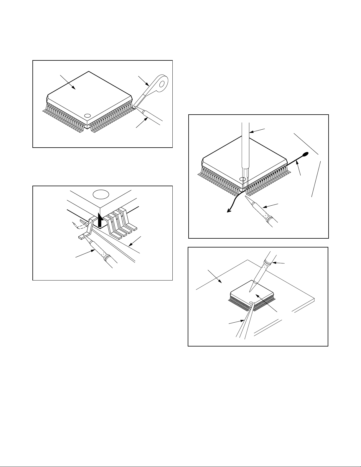
With Soldering Iron:
(1) Using desoldering braid, remove the solder from all
pins of the flat pack-IC. When you use solder flux
which is applied to all pins of the flat pack-IC, you
can remove it easily. (Fig. S-1-3)
Flat Pack-IC
Desoldering Braid
(4) Bottom of the flat pack-IC is fixed with glue to the
CBA; when removing entire flat pack-IC, first apply
soldering iron to center of the flat pack-IC and heat
up. Then remove (glue will be melted). (Fig. S-1-6)
(5) Release the flat pack-IC from the CBA using twee-
zers. (Fig. S-1-6)
Note:
When using a soldering iron, care must be taken
to ensure that the flat pack-IC is not being held by
glue. When the flat pack-IC is removed from the
CBA, handle it gently because it may be damaged
if force is applied.
Soldering Iron
Fig. S-1-3
(2) Lift each lead of the flat pack-IC upward one by
one, using a sharp pin or wire to which solder will
not adhere (iron wire). When heating the pins, use
a fine tip soldering iron or a hot air desoldering
machine. (Fig. S-1-4)
Sharp
Pin
Fine Tip
Soldering Iron
Fig. S-1-4
(3) Bottom of the flat pack-IC is fixed with glue to the
CBA; when removing entire flat pack-IC, first apply
soldering iron to center of the flat pack-IC and heat
up. Then remove (glue will be melted). (Fig. S-1-6)
(4) Release the flat pack-IC from the CBA using twee-
zers. (Fig. S-1-6)
With Iron Wire:
(1) Using desoldering braid, remove the solder from all
pins of the flat pack-IC. When you use solder flux
which is applied to all pins of the flat pack-IC, you
can remove it easily. (Fig. S-1-3)
(2) Affix the wire to a workbench or solid mounting
point, as shown in Fig. S-1-5.
(3) While heating the pins using a fine tip soldering
iron or hot air blower, pull up the wire as the solder
melts so as to lift the IC leads from the CBA contact
pads as shown in Fig. S-1-5
To Solid
Mounting Point
CBA
Tweezers
Hot Air Blower
or
Iron Wire
Soldering Iron
Fig. S-1-5
Fine Tip
Soldering Iron
Flat Pack-IC
Fig. S-1-6
1-5
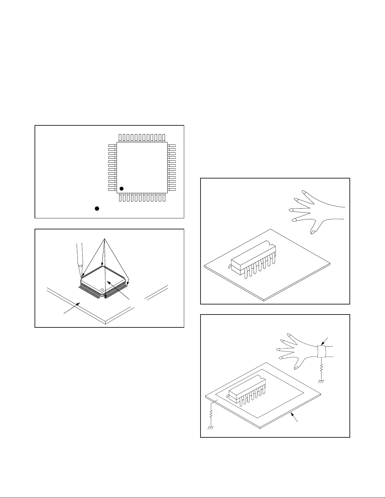
2. Installation
(1) Using desoldering braid, remove the solder from
the foil of each pin of the flat pack-IC on the CBA
so you can install a replacement flat pack-IC more
easily.
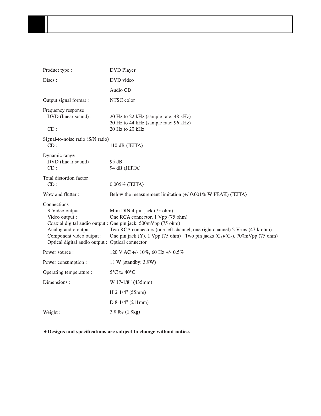
(2) The “I” mark on the flat pack-IC indicates pin 1.
(See Fig. S-1-7.) Be sure this mark matches the 1
on the PCB when positioning for installation. Then
presolder the four corners of the flat pack-IC. (See
Fig. S-1-8.)
(3) Solder all pins of the flat pack-IC. Be sure that none
of the pins have solder bridges.
Example :
Pin 1 of the Flat Pack-IC
is indicated by a " " mark.
Fig. S-1-7
1-3-4 Instructions for Handling
Semi-conductors
Electrostatic breakdown of the semi-conductors may
occur due to a potential difference caused by electrostatic charge during unpacking or repair work.
1. Ground for Human Body
Be sure to wear a grounding band (1MΩ) that is properly grounded to remove any static electricity that may
be charged on the body.
2. Ground for Workbench
(4) Be sure to place a conductive sheet or copper plate
with proper grounding (1MΩ) on the workbench or
other surface, where the semi-conductors are to be
placed. Because the static electricity charge on
clothing will not escape through the body grounding band, be careful to avoid contacting semi-conductors with your clothing.
< Incorrect >
CBA
Presolder
Flat Pack-IC
Fig. S-1-8
CBA
< Correct >
Grounding Band
1MΩ
CBA
1MΩ
Conductive Sheet or
Copper Plate
1-6
GENERAL INFORMATION2
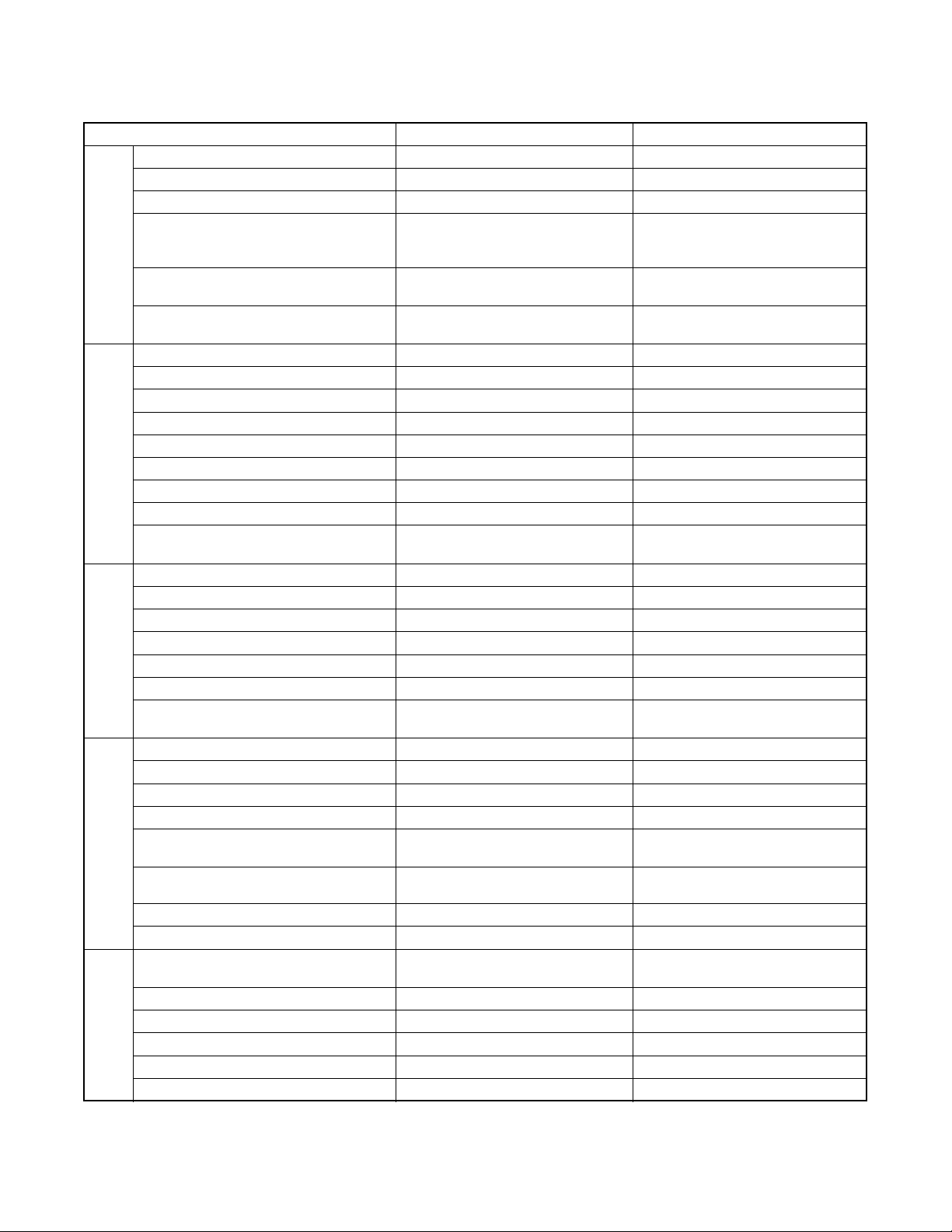
2-1 SPECIFICATIONS
2-1
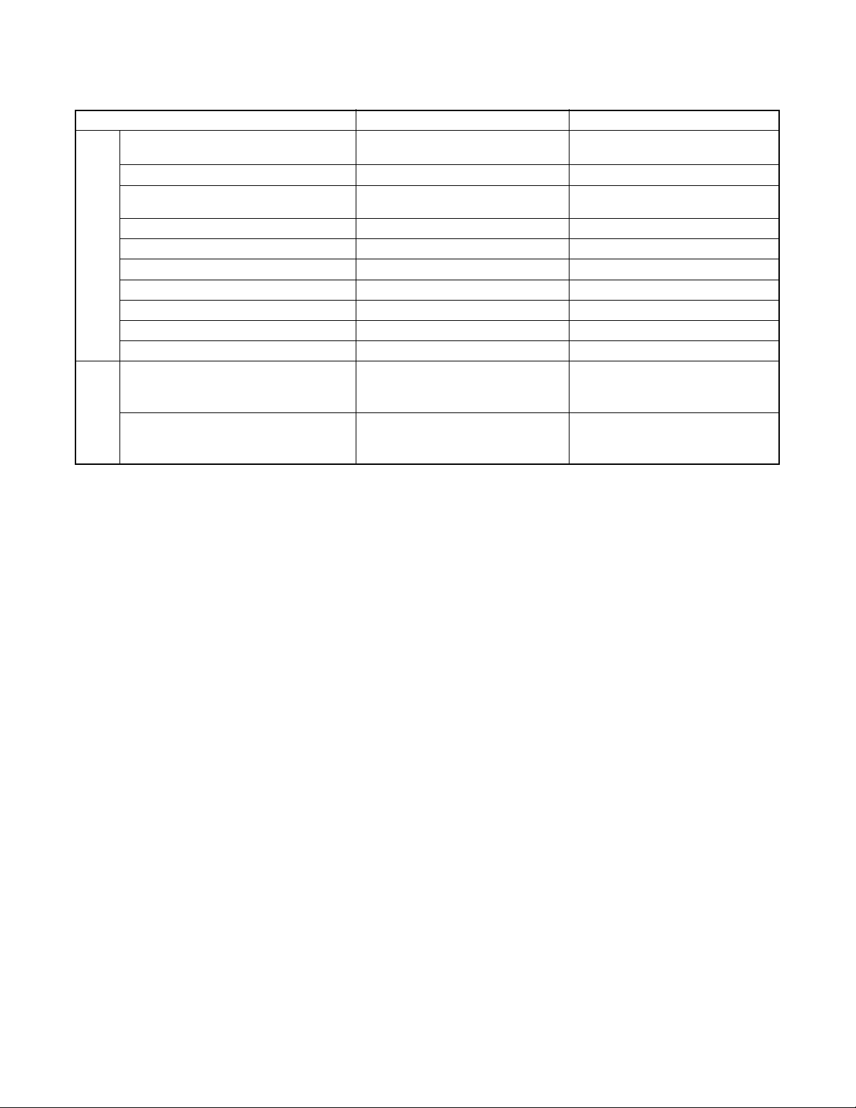
2-2 COMPARISON OF MODELS
A
E
G
L
V
O
A
O
T
Y
←: Same as on left
ITEM
Dimensional 435(W) x 55(H) x 211(D) mm 435(W) x 75(H) x 216(D) mm
Weight 1.8 kg 2.1 kg
Tray Panel Clear Silver
Color Front / Button
PPEARANC
Hot Stamp ---
Ultra Vision Badge --Drive Speed 1x ←
Laser 2 ←
DVD/VCD/SVCD/CD-DA O / --- / --- / O ←
CD-R/CD-RW/DVD-R (Video Format) O / O / O ←
DVD-RAM (VR Format) --- ←
MP3 O ---
ENERA
OSD languages 3 (English, French, Spanish) ←
Jog Shuttle on Front --- Only switch shuttle
Headphone Jack / Volume --- / --PAL Disc NTSC Out --- O
Video Out Mode NTSC/PAL/PAL60 O / --- / --- ←
S-Video / Component / Composite O / O / O ←
Video D/A Converter 10bit ←
IDE
Black Level Select O ←
Picture Control --- ←
Progressive Out
Audio D/A Converter 192kHz / 24bit ←
Digital Audio Out Optical / Coaxial --- / O O / O
Dolby Digital 5.1 ch Decode --- ←
DTS Digital Out --- O
Virtual Surround O
UDI
Dynamic Range Compression (Dolby
Digital)
DVD Audio --- ←
Power on sound --- ←
Search Speed
Slow Speed 1/16, 1/8, 1/2 (FORWARD/REWIND) 1/16, 1/8, 1/2 (FORWARD only)
IP Search (Smooth 2x Play) O ←
2x Play with Audio --- ←
RICK PLA
Step Forward / Reverse O / O O / --Still Picture Select (Frame/Field) Auto Only ←
DV-P735U/P735U(C)/P533U DV-P725U/P325U/P323U
Silver/Silver (DV-P735U/P735U(C))
Black/Silver (DV-P533U)
O (DV-P735U/P735U(C))
--- (DV-P533U)
O ←
2 to 100 (FORWARD/REWIND)
(DVD: 2, 8, 50, 100/CD: 16)
Dark Silver/Silver (DV-P725U)
Black/Silver (DV -P32 5U)
Silver/Silver (DV-P323U)
O (DV-P725U)
--- (DV-P325U/P323U)
O (DV-P725U)
--- (DV-P325U/P323U)
O / O (DV-P725U)
--- / --- (DV-P325U/P323U)
O (DV-P725U)
--- (DV-P325U/P323U)
O (DV-P725U/P325U)
--- (DV-P323U)
2 to 60 (FORWARD/REWIND)
(DVD: 2, 8, 30, 60/CD: 16)
2-2
ITEM
Disc Navigation
DVD Zoom x2 / x4 / x16 O / O / --- ←
Program and Random Play of DVD /
VCD
A-B Repeat O ←
Repeat O ←
Last Play O ←
FEATURES
Closed Caption for NTSC DVD O ←
Front Panel Display Dimmer O ←
Screen Saver O ←
Auto Power Off O ←
Jog Shuttle on Remote --- ←
DV-P735U/P735U(C)/P533U DV-P725U/P325U/P323U
O (DV-P735U/P735U(C))
--- (DV-P533U)
--- ←
---
REMOTE
TV Control
CONTROLLER
O (DV-P735U/P735U(C))
--- (DV-P533U)
O
2-3

2-3 OPERATING CONTROLS AND FUNCTIONS
[ DV-P735U/P735(C) ]
FRONT PANEL
y/I POWER/
STANDBY
H/E
SKIP/FR
1 6
D/G
B
FF/SKIP
PLAY
STOP
C
A
OPEN/CLOSE
REAR VIEW
ANALOG AUDIO OUT
DIGTAL AUDIO OUT
COAXIAL
1. y/I (POWER/STANDBY)
to switch the player to ON or OFF
(As to the indication of the Operate switch, “I” indicates
ON and “y” indicates electrical power STANDBY)
2. SKIP/FR
goes to previous chapter or track during playback; press
and hold for 1.5 seconds for a reverse search
3. PLAY
to start or resume disc playback
4. FF/SKIP
goes to next chapter or track during playback; press and
hold for 1.5 seconds for a forward search
5. STOP
to stop playback
6. OPEN/CLOSE
to open/close the disc tray
7. Disc tray
8. Display
CR/PR
LY
VIDEO
RCB/PB
OUT
13 151211910 14
COMPONENT
VIDEO OUT
S-VIDEO
OUT
I P
PROGRESSIVE
7
82 3 4 5
9. MAIN (AC Power Cord)
connect to a standard AC outlet
10. COAXIAL (Digital audio out)
connect to AUDIO inputs of a digital (coaxial) audio
equipment
11. AUDIO OUT (Left/Right)
connect to AUDIO inputs of an amplifier, receiver or
stereo system
12. VIDEO OUT
connect to the Video Input of a TV.
13. COMPONENT VIDEO OUT
connect to a TV with Component video in jacks.
14. S-VIDEO OUT
connect to a TV with S-Video inputs
15. INTERLACE/PROGRESSIVE SCAN SELECTOR
to select interlace or progressive scanning
Caution: Do not touch the inner pins of the jacks on the
rear panel. Electrostatic discharge may cause permanent
damage to the player.
2-4
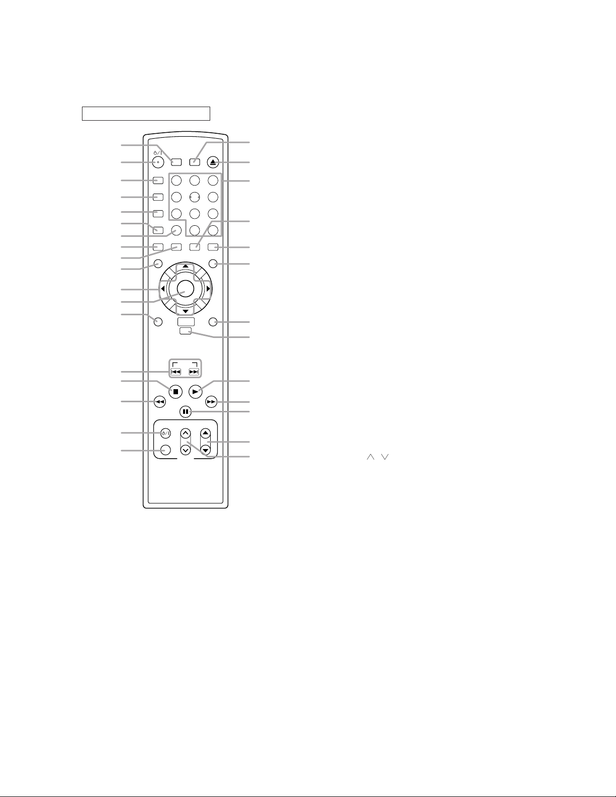
REMOTE CONTROL
y
y
B
o
h
p
o
D
1
SURROUND
2
A-B REPEAT
3
4
5
6
7
8
9
REPEAT
MODE
ZOOM
ANGLE
MENU
1
4
7
CLEAR
SUBTITLE
10
11
ENTER
12
13
RETURN
NAVIGATION
SKIP
14
15
16
STOP
PAUSE/STEP
TV POWER
17
18
VIDEO/TV
SEARCH
MODE
2
56
8
0
AUDIO
DISC
PLAY
VOL
TV
OPEN
CLOSE
3
9
+10
DISPLAY
TOP MENU
SETUP
CH
31
30
29
28
27
26
25
24
23
22
21
20
19
1. SURROUND
Press to activate the virtual sound.
y
2.
/I
(POWER/STANDBY)
Press to turn the power on and off.
(As to the indication of the Operate switch, "I" shows
ON and "
y
/I" shows electrical power stand-by.)
3. A-B REPEAT
Repeats playback of a selected section.
4. REPEAT
Repeats playback of the current disc, title, chapter or
track.
5. MODE
Activates program playback or random playback mode
when playing CDs or MP3. Sets Black level and virtual
surround.
6. ZOOM
Enlarges part of a DVD-reproduced image.
7. CLEAR
Press to reset the setting.
8. ANGLE
Press to change the camera angle to see the sequence
being played back from a different angle.
9. SUBTITLE
Press to select the desired subtitle language.
10. MENU
Press to display the menu of the Disc.
11. Arrow Buttons (
ss B
ppo
)
Move the cursor and determines its position.
12. ENTER
Press to accept a setting.
13. RETURN
Returns to the previous operation.
14. SKIP
Press to skip Chapters or Tracks.
15. STOP
Press to stop the disc motion.
h
16.
Press to view the DVD picture in fast reverse motion or
to (reverse playback of an Audio CD.
17. TV POWER
To exclusively turn ON/OFF the TV.
18. VIDEO/TV
Press to select the external input mode or TV mode of
the TV.
19. TV VOL ( / )
Press to exclusively control the TV volume.
p
20. TV CH
o
/
Press to exclusively control the TV channels.
21. PAUSE/STEP
Press to pause Disc playback. Press repeatedly to
advance the DVD picture step by step (or one frame at
a time).
D
22.
Press to fast forward the Disc. Press PAUSE/STEP,
then press this button to begin slow motion playback.
Press this button repeatedly to change the forward
speed of slow motion.
23. PLAY
Press to begin playback.
24. DISC NAVIGATION
Press to enter the setup mode.
25. SETUP
Press to display the first scenes of each chapter of the
title being played.
26. TOP MENU
Press to call up the title menu.
27. DISPLAY
Press to access or remove the display screen during
DVD or Audio CD playback.
28. AUDIO
Press to select a desired audio language or sound
mode.
29. Numerical Buttons
Press to directly select a Track (Audio CD) for playback.
30. OPEN/CLOSE
Press to open or close the disc loading tray.
31. SEARCH MODE
Press to access or remove the Search display, which
allows you to go directly to a specific
Title/Chapter/Track/Time
.
2-5
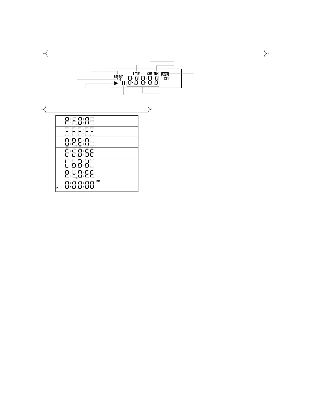
Display
Stays on when
the repeat function is on.
Stays on when
the A-B repeat
function is on.
Stays on when repeat
title function is on.
Stays on when repeat chapter function is on.
Stays on when repeat track function is on.
Lights up when a DVD
is inserted into the tray.
Lights up when a CD is
inserted into the tray.
Stays on when the inserted
disc is being played back.
Displays During Operation
Power on
No disc inserted/can not read
Tray open
Tray closed
Loading the Disc
Power off
When a disc is being
Play back
Lights up when the
inserted disc comes
to a pause.
Displays how long a current title or track has been
played back. When a chapter or track has switched,
the number of a new title, chapter or track is displayed.
2-6
[ DV-P533U ]
h
KLL
g
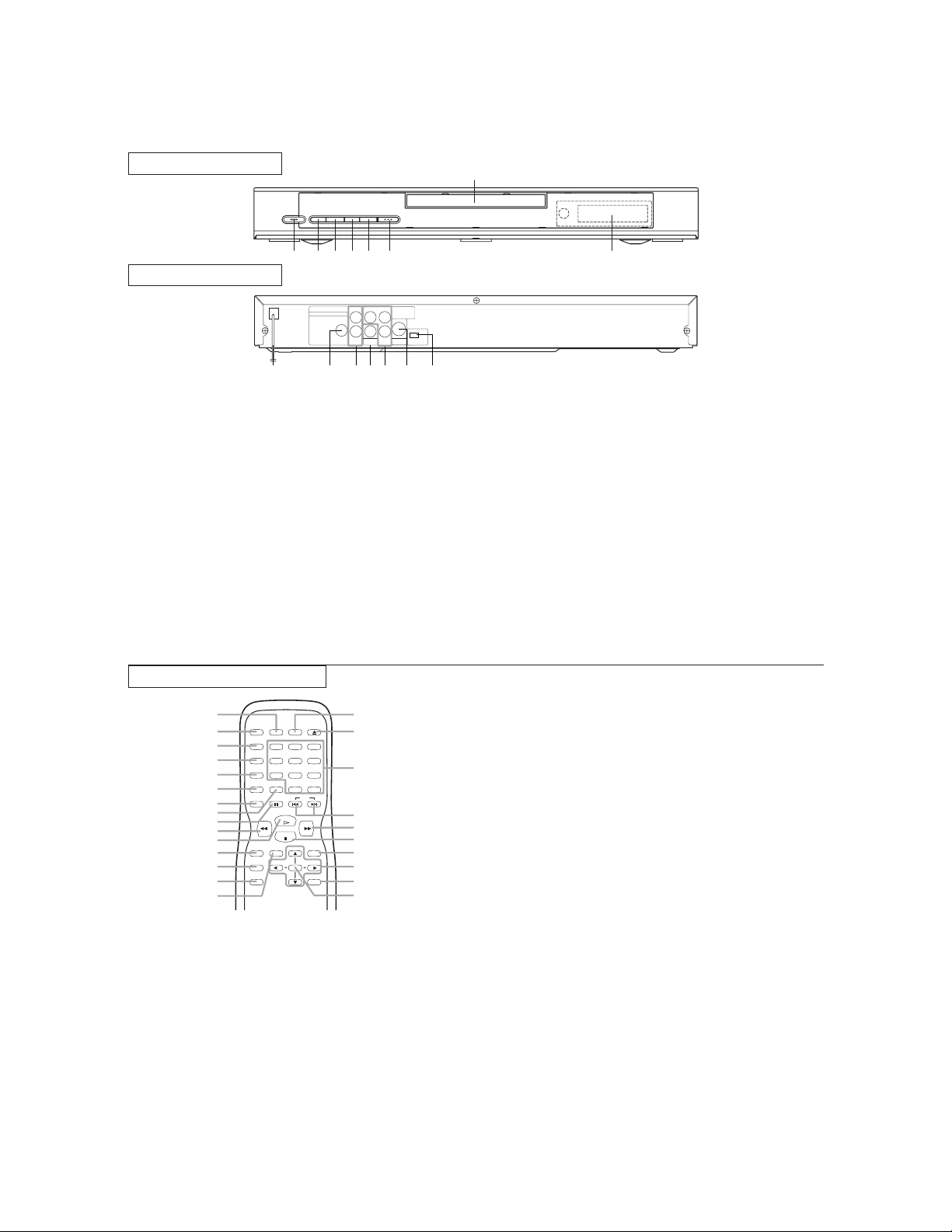
FRONT PANEL
H/E
D/G
B
SKIP/FR
FF/SKIPAOPEN/CLOSE
y/I POWER/
STANDBY
PLAYCSTOP
1 6
REAR VIEW
ANALOG AUDIO OUT
DIGTAL AUDIO OUT
COAXIAL
1. y/I (POWER/STANDBY)
to switch the player to ON or OFF
(As to the indication of the Operate switch, “I” indicates
ON and “y” indicates electrical power STANDBY)
2. SKIP/FR
goes to previous chapter or track during playback; press
and hold for 1.5 seconds for a reverse search
3. PLAY
to start or resume disc playback
4. FF/SKIP
goes to next chapter or track during playback; press and
hold for 1.5 seconds for a forward search
5. STOP
to stop playback
6. OPEN/CLOSE
to open/close the disc tray
7. Disc tray
8. Display
LY
VIDEO
RCB/PB
OUT
CR/PR
COMPONENT
VIDEO OUT
S-VIDEO
OUT
13 151211910 14
I P
PROGRESSIVE
7
82 3 4 5
9. MAIN (AC Power Cord)
connect to a standard AC outlet
10. COAXIAL (Digital audio out)
connect to AUDIO inputs of a digital (coaxial) audio
equipment
11. AUDIO OUT (Left/Right)
connect to AUDIO inputs of an amplifier, receiver or
stereo system
12. VIDEO OUT
connect to the Video Input of a TV.
13. COMPONENT VIDEO OUT
connect to a TV with Component video in jacks.
14. S-VIDEO OUT
connect to a TV with S-Video inputs
15. INTERLACE/PROGRESSIVE SCAN SELECTOR
to select interlace or progressive scanning
Caution: Do not touch the inner pins of the jacks on the
rear panel. Electrostatic discharge may cause permanent
damage to the player.
REMOTE CONTROL
1
y
/I
2
AUDIO
3
SUBTITLE
4
ANGLE
5
REPEAT
6
A-B REPEAT
7
8
9
10
11
SETUP
12
MODE
13
ZOOM
14
15
DISPLAY
123
456
789
CLEAR
0 +10
SKIP
PAUSE/STEP
PLAY
STOP
TOP MENU
ENTER
OPEN/CLOSESEARCH MODE
1. DISPLAY
to access or remove the display screen during DVD or
Audio CD playback
2. y/I (POWER/STANDBY)
switch DVD player ON or OFF
3. AUDIO
to choose audio languages or sound modes
4. SUBTITLE
subtitle language DVD selector
5. ANGLE
select DVD camera angle
6. REPEAT
repeat chapter, track, title, all.
7. A-B REPEAT
repeat a specific segment
8. CLEAR
to reset the setting
MENU
RETURN
25
24
23
22
21
20
19
18
17
16
9. PAUSE/STEP
pause playback temporarily / frame-by-frame playback
h
10.
to view DVD picture in fast reverse motion
11. PLAY
to start a DVD disc playback
12. SETUP
to access or remove the DVD setup menu
13. MODE
to set up programmed or random playback (Audio CD)
to set the black level and virtual surround during DVD
playback
14. ZOOM
enlarge DVD video image
15. TOP MENU
to display title menu of a disc
16. ENTER
acknowledge menu selection
17. RETURN
to return previous or remove setup menu
18. Arrow (sB
(left/right/up/down) select an item in the menu
19. MENU
to display the menu of the DVD disc
20. STOP
to stop a DVD disc playback
g
21.
to view DVD picture in fast forward motion
22. SKIP H,G
to skip chapter/tracks
23. 0-9 numerical buttons
select numbered items in a menu
+10
use this button to enter number 10 and above
24. OPEN/CLOSE
to open/close the disc tray
25. SEARCH MODE
to locate a desired point
K
)
2-7

Display
Stays on when
the repeat function is on.
Stays on when
the A-B repeat
function is on.
Stays on when repeat
title function is on.
Stays on when repeat chapter function is on.
Stays on when repeat track function is on.
Lights up when a DVD
is inserted into the tray.
Lights up when a CD is
inserted into the tray.
Stays on when the inserted
disc is being played back.
Displays During Operation
Power on
No disc inserted
Tray open
Tray closed
Loading the Disc
Power off
When a disc is being
Play back
Lights up when the
inserted disc comes
to a pause.
Displays how long a current title or track has been
played back. When a chapter or track has switched,
the number of a new title, chapter or track is displayed.
2-8
 Loading...