

Page 1

MODEL Variable speed CORDLESS HAMMER DRILL
MODÈLE MARTEAU PERFORATEUR À BATTERIE
MODELO MARTILLO ROTO-PERCUTOR A BATERÍA
DV 24DV
SAFETY INSTRUCTIONS AND INSTRUCTION MANUAL
WARNING
IMPROPER OR UNSAFE use of this power tool can result in death or serious bodily
injury!
This manual contains important information about product safety. Please read
and understand this manual BEFORE operating the power tool. Please keep this
manual available for other users and owners before they use the power tool. This
manual should be stored in safe place.
INSTRUCTIONS DE SECURITE ET MODE D’EMPLOI
AVERTISSEMENT
Une utilisation INCORRECTE OU DANGEREUSE de cet outil motorisé peut entraîner
la mort ou de sérieuses blessures corporelles!
Ce mode d’emploi contient d’importantes informations à propos de la sécurité de
ce produit. Prière de lire et de comprendre ce mode d’emploi AVANT d’utiliser
l’outil motorisé. Garder ce mode d’emploi à la disponibilité des autres utilisateurs
et propriétaires avant qu’ils utilisent l’outil motorisé. Ce mode d’emploi doit être
conservé dans un endroit sûr.
INSTRUCCIONES DE SEGURIDAD Y MANUAL DE INSTRUCCIONES
ADVERTENCIA
¡La utilización INAPROPIADA O PELIGROSA de esta herramienta eléctrica puede
resultar en lesiones de gravedad o la muerte!
Este manual contiene información importante sobre la seguridad del producto.
Lea y comprenda este manual ANTES de utilizar la herramienta eléctrica. Guarde
este manual para que puedan leerlo otras personas antes de utilizar la herramienta
eléctrica. Este manual debe ser guardado en un lugar seguro.
Page 2

English
English
IMPORTANT SAFETY INFORMATION ............................. 3
MEANINGS OF SIGNAL WORDS ..................................... 3
SAFETY .............................................................................. 4
GENERAL SAFETY RULES – FOR ALL BATTERY
OPERATED TOOLS .................................................. 4
SPECIFIC SAFETY RULES AND SYMBOLS ................ 6
IMPORTANT SAFETY INSTRUCTIONS FOR
BATTERY CHARGER ................................................ 8
IMPORTANT SAFETY INSTRUCTIONS FOR USE OF
THE BATTERY AND BATTERY CHARGER ............. 9
FUNCTIONAL DESCRIPTION .......................................... 11
MODEL ........................................................................ 11
NAME OF PARTS ........................................................ 11
SPECIFICATIONS ........................................................ 12
Français
INFORMATIONS IMPORTANTES DE SÉCURITÉ ............ 28
SIGNIFICATION DES MOTS D’AVERTISSEMENT .......... 28
SECURITE .......................................................................... 29
REGLES GENERALE DE SECURITE – POUR TOUS
LES OUTILS FONCTIONNANT SUR BATTERIE ..... 29
REGLES DE SECURITE SPECIFIQUES ET SYMBOLES ...
CONSIGNES DE SÉCURITÉ IMPORTANTES POUR
L’UTILISATION DU CHARGEUR DE BATTERIE ..... 33
CONSIGNES DE SÉCURITÉ IMPORTANTES POUR
L’UTILISATION DE LA BATTERIE ET DU
CHARGEUR DE BATTERIE ...................................... 34
DESCRIPTION FONCTIONNELLE ..................................... 36
MODELE ........................................................................ 36
NOM DES PARTIES ...................................................... 36
SPECIFICATIONS .......................................................... 37
TABLE DES MATIERES
CONTENTS
Page
ASSEMBLY AND OPERATION ....................................... 14
APPLICATIONS ........................................................... 14
REMOVAL AND INSTALLATION METHOD
OF BATTERY .......................................................... 14
CHARGING METHOD ................................................. 14
BEFORE USE ............................................................... 17
PRIOR TO OPERATION .............................................. 17
HOW TO USE .............................................................. 21
MAINTENANCE AND INSPECTION ............................... 23
ACCESSORIES ................................................................. 26
STANDARD ACCESSORIES ....................................... 26
OPTIONAL ACCESSORIES ......................................... 26
PARTS LIST ........................................................................ 78
Page
ASSEMBLAGE ET FONCTIONNEMENT .......................... 39
UTILISATIONS .............................................................. 39
MÉTHODE DE RETRAIT ET D’INSTALLATION
DE LA BATTERIE ...................................................... 39
MÉTHODE DE RECHARGE ........................................... 39
AVANT L’UTILISATION ................................................ 42
31
AVANT LA MISE EN MARCHE .................................... 42
UTILISATION ................................................................ 47
ENTRETIEN ET INSPECTION ............................................ 48
ACCESOIRES ..................................................................... 51
ACCESSOIRES STANDARD ......................................... 51
ACCESSOIRES EN OPTION ......................................... 51
LISTE DES PIÈCES ............................................................. 78
Page
Page
Español
INFORMACIÓN IMPORTANTE SOBRE SEGURIDAD ...... 53
SIGNIFICADO DE LAS PALABRAS DE SEÑALIZACIÓN53
SEGURIDAD ....................................................................... 54
NORMAS GENERALES DE SEGURIDAD – PARA
TODAS LAS HERRAMIENTAS ALIMENTADAS
CON BATERÍA .......................................................... 54
NORMAS Y SÍMBOLOS ESPECÍFICOS DE
SEGURIDAD ............................................................. 56
INSTRUCCIONES IMPORTANTES DE SEGURIDAD
PARA EL CARGADOR DE BATERÍAS ..................... 58
INSTRUCCIONES IMPORTANTES DE SEGURIDAD
PARA LA BATERÍA Y EL CARGADOR DE BATERÍAS
DESCRIPCIÓN FUNCIONAL .............................................. 61
MODELO ....................................................................... 61
NOMENCLATURA ........................................................ 61
ESPECIFICACIONES ..................................................... 62
2
Página
ÍNDICE
MONTAJE Y OPERACIÓN ................................................ 64
APLICACIONES ............................................................. 64
MÉTODO DE EXTRACCIÓN E INSTALACIÓN
DE LA BATERÍA ........................................................ 64
MÉTODO DE CARGA .................................................... 64
ANTES DE LA UTILIZACIÓN ........................................ 67
ANTES DE USAR LA HERRAMIENTA ......................... 67
COMO SE USA ............................................................. 72
MANTENIMIENTO E INSPECCIÓN .................................. 73
ACCESORIOS ..................................................................... 76
.. 59
ACCESORIOS ESTÁNDAR ........................................... 76
ACCESORIOS OPCIONALES ........................................ 76
LISTA DE PIEZAS .............................................................. 78
Página
Page 3

English
IMPORTANT SAFETY INFORMATION
Read and understand all of the safety precautions, warnings and operating instructions in
the Instruction Manual before operating or maintaining this power tool.
Most accidents that result from power tool operation and maintenance are caused by the
failure to observe basic safety rules or precautions. An accident can often be avoided by
recognizing a potentially hazardous situation before it occurs, and by observing appropriate
safety procedures.
Basic safety precautions are outlined in the “SAFETY” section of this Instruction Manual and
in the sections which contain the operation and maintenance instructions.
Hazards that must be avoided to prevent bodily injury or machine damage are identified by
WARNINGS on the power tool and in this Instruction Manual.
NEVER use this power tool in a manner that has not been specifically recommended by
HITACHI.
MEANINGS OF SIGNAL WORDS
WARNING indicates a potentially hazardous situations which, if ignored, could result in
death or serious injury.
CAUTION indicates a potentially hazardous situations which, if not avoided, may result in
minor or moderate injury, or may cause machine damage.
NOTE emphasizes essential information.
3
Page 4

English
SAFETY
GENERAL SAFETY RULES – FOR ALL BATTERY OPERATED TOOLS
WARNING: Read and understand all instructions.
Failure to follow all instructions listed below, may result in electric shock,
fire and/or serious personal injury.
SAVE THESE INSTRUCTIONS
1. Work Area
(1) Keep your work area clean and well lit. Cluttered benches and dark areas invite
accidents.
(2) Do not operate power tools in explosive atmospheres, such as in the presence of
flammable liquids, gases, or dust. Power tools create sparks which may ignite the
dust of fumes.
(3) Keep bystanders children, and visitors away while operating a power tool.
Distractions can cause you to lose control.
2. Electrical Safety
(1) A battery operated tool with integral batteries or a separate battery pack must be
recharged only with the specified charger for the battery.
A charger that may be suitable for one type of battery may create a risk of fire when
used with another battery.
(2) Use battery operated tool only with specifically designed battery pack.
Use of any other batteries may create a risk of fire.
3. Personal Safety
(1) Stay alert, watch what you are doing and use common sense when operating a
power tool. Do not use tool while tired or under the influence of drugs, alcohol, or
medication. A moment of inattention while operating power tools may result in
serious personal injury.
(2) Dress properly. Do not wear loose clothing or jewelry. Contain long hair. Keep your
hair, clothing and gloves away from moving parts. Loose clothes, jewelry, or long hair
can be caught in moving parts.
(3) Avoid accidental starting. Be sure switch is off position before inserting battery.
Carrying tools with your finger on the switch or inserting the battery pack into a tool
with the switch on invites accidents.
(4) Remove adjusting keys or wrenches before turning the tool on. A wrench or a key that
is left attached to a rotating part of the tool may result in personal injury.
(5) Do not overreach. Keep proper footing and balance at all times. Proper footing and
balance enable better control of the tool in unexpected situations.
(6) Use safety equipment. Always wear eye protection. Dust mask, non-skid safety
shoes, hard hat, or hearing protection must be used for appropriate conditions.
4. Tool Use and Care
(1) Use clamps or other practical way to secure and support the workpiece to a stable
platform. Holding the work by hand or against your body is unstable and may lead to
loss of control.
4
Page 5

English
(2) Do not force tool. Use the correct tool for your application. The correct tool will do
the job better and safer at the rate for which it is designed.
(3) Do not use tool if switch does not turn it on or off. Any tool that cannot be controlled
with the switch is dangerous and must be repaired.
(4) Disconnect battery pack from tool or place the switch in the locked or off position
before making any adjustments, changing accessories, or storing the tools. Such
preventive safety measures reduce the risk of starting the tool accidentally.
(5) Store idle tools out of reach of children and other untrained persons. Tools are
dangerous in the hands of untrained users.
(6) When battery pack is not in use, keep it away from other metal objects like: paper
clips, coins, keys, nails, screws, or other small metal objects that can make a
connection from one terminal to another.
Shorting the battery terminals together may cause sparks, burns, or a fire.
(7) Maintain tools with care. Keep cutting tools sharp and clean. Properly maintained
tools, with sharp cutting edges are less likely to bind and are easier to control.
(8) Check for misalignment or binding of moving parts, breakage of parts, and any other
condition that may affect the tools operation. If damaged, have the tool serviced
before using. Many accidents are caused by poorly maintained tools.
(9) Use only accessories that are recommended by the manufacturer for your model.
Accessories that may be suitable for one tool, may become hazardous when used on
another tool.
5. Service
(1) Tool service must be performed only by qualified repair personnel. Service or
maintenance performed by unqualified personnel could result in a risk of injury.
(2) When servicing a tool, use only identical replacement parts. Follow instructions in
the Maintenance section of this manual. Use of unauthorized parts or failure to follow
Maintenance Instruction may create a risk of electric shock or injury.
WARNING:
Some dust created by power sanding, sawing, grinding, drilling, and other construction
activities contains chemicals known to the State of California to cause cancer, birth
defects or other reproductive harm. Some examples of these chemicals are:
● Lead from lead-based paints,
● Crystalline silica from bricks and cement and other masonry products, and
● Arsenic and chromium from chemically-treated lumber.
Your risk from these exposures varies, depending on how often you do this type of work.
To reduce your exposure to these chemicals: work in a well ventilated area, and work
with approved safety equipment, such as those dust masks that are specially designed
to filter out microscopic particles.
5
Page 6

English
SPECIFIC SAFETY RULES AND SYMBOLS
1. Hold tools by insulated gripping surfaces when performing an operation where the
cutting tool may contact hidden wiring. Contact with a “live” wire will make exposed
metal parts of the tool “live” and shock the operator.
2. ALWAYS wear ear plugs when using the tool for extended periods.
Prolonged exposure to high intensity noise can cause hearing loss.
3. NEVER touch the tool bit with bare hands after operation.
4. NEVER wear gloves made of stuff liable to roll up such as cotton, wool, cloth or string,
etc.
5. ALWAYS attach the side handle with handle joint and securely grip the Drill.
6. NEVER touch moving parts.
NEVER place your hands, fingers or other body parts near the tool’s moving parts.
7. NEVER operate without all guards in place.
NEVER operate this tool without all guards or safety features in place and in proper
working order. If maintenance or servicing requires the removal of a guard or safety
feature, be sure to replace the guard or safety feature before resuming operation of the
tool.
8. Use right tool.
Don’t force small tool or attachment to do the job of a heavy-duty tool.
Don’t use tool for purpose not intended —for example— don’t use circular saw for
cutting tree limbs or logs.
9. NEVER use a power tool for applications other than those specified.
NEVER use a power tool for applications other than those specified in the Instruction
Manual.
10. Handle tool correctly.
Operate the tool according to the instructions provided herein. Do not drop or throw the
tool. NEVER allow the tool to be operated by children, individuals unfamiliar with its
operation or unauthorized personnel.
11. Keep all screws, bolts and covers tightly in place.
Keep all screws, bolts, and plates tightly mounted. Check their condition periodically.
12. Do not use power tools if the plastic housing or handle is cracked.
Cracks in the tool’s housing or handle can lead to electric shock. Such tools should not
be used until repaired.
13. Blades and accessories must be securely mounted to the tool.
Prevent potential injuries to youself or others. Blades, cutting implements and accessories
which have been mounted to the tool should be secure and tight.
6
Page 7

English
14. Keep motor air vent clean.
The tool’s motor air vent must be kept clean so that air can freely flow at all times. Check
for dust build-up frequently.
15. NEVER use a tool which is defective or operating abnormally.
If the tool appears to be operating unusually, making strange noises, or otherwise
appears defective, stop using it immediately and arrange for repairs by a Hitachi
authorized service center.
16. NEVER leave tool running unattended. Turn power off.
Don’t leave tool until it comes to a complete stop.
17. Carefully handle power tools.
Should a power tool be dropped or struck against hard materials inadvertently, it may
be deformed, cracked, or damaged.
18. Do not wipe plastic parts with solvent.
Solvents such as gasoline, thinner benzine, carbon tetrachloride, and alcohol may
damage and crack plastic parts. Do not wipe them with such solvents.
Wipe plastic parts with a soft cloth lightly dampened with soapy water and dry
thoroughly.
19. ALWAYS wear eye protection that meets the requirement of the latest revision of ANSI
Standard Z87.1.
20. Definitions for symbols used on this tool
V ... volts
--- .. direct current
n
o... no load speed
---/min .... revolutions or reciprocation per minute
7
Page 8

English
IMPORTANT SAFETY INSTRUCTIONS
FOR BATTERY CHARGER
WARNING: Death or serious bodily injury could result from improper or unsafe use
of power tools. To avoid these risks, follow these basic safety instructions:
READ ALL INSTRUCTIONS
1. This manual contains important safety and operating instructions for battery charger
Model UC24YFB.
2. Before using battery charger, read all instructions and cautionary markings on (1) battery
charger, (2) battery, and (3) product using battery.
3. To reduce risk of injury, charge HITACHI rechargeable battery type EB2420. Other type
of batteries may burst causing personal injury and damage.
4. Do not expose battery charger to rain or snow.
5. Use of an attachment not recommended or sold by the battery charger manufacturer may
result in a risk of fire, electric shock, or injury to persons.
6. To reduce risk of damage to electric plug and cord, pull by plug when disconnecting
battery charger.
7. Make sure cord is located so that it will not be stepped on, tripped over, or otherwise
subjected to damage or stress.
8. An extension cord should not be used unless absolutely necessary. Use of improper
extension cord could result in a risk of fire and electric shock.
If extension cord must be used make sure:
a. That blades of extension cord are the same number, size, and shape as those of plug
on battery charger:
b. That extension cord is properly wired and in good electrical condition; and
c. That wire size is large enough for AC ampere rating of battery charger as specified
in Table 1.
RECOMMENDED MINIMUM AWG SIZE FOR
EXTENSION CORDS FOR BATTERY CHARGERS
AC Input Rating Amperes* AWG Size of Cord
Equal to or but less Length of Cord, Feet (Meter)
greater than than 25 (7.5) 50 (15) 100 (30) 150 (45)
0 2 18 18 18 16
2 3 18 18 16 14
3 4 18 18 16 14
Table 1
* If the input rating of a battery charger is given in watts rather than in amperes, the
corresponding ampere rating is to be determined by dividing the wattage rating by the
voltage rating–for example:
1250watts
125 volts
8
= 10 amperes
Page 9

English
9. Do not operate battery charger with damaged cord or plug-replace them immediately.
10. Do not operate battery charger if it has received a sharp blow, been dropped, or
otherwise damaged in any way; take it to a qualified serviceman.
11. Do not disassemble battery charger; take it to a qualified serviceman when service or
repair is required. Incorrect reassembly may result in a risk of electric shock or fire.
12. To reduce risk of electric shock, unplug charger from receptacle before attempting any
maintenance or cleaning. Removing the battery will not reduce this risk.
13. This battery charger might be attached to HITACHI battery operated tools as a standard
accessory. In this case, please confirm instruction Manual of the HITACHI battery
operated tools before using the battery charger.
IMPORTANT SAFETY INSTRUCTIONS FOR USE OF THE
BATTERY AND BATTERY CHARGER
You must charge the battery before you can use the cordless hammer drill. Before using the
model UC24YFB battery charger, be sure to read all instructions and cautionary statements
on it, the battery and in this manual.
REMEMBER: USE ONLY HITACHI BATTERY TYPE EB2420. OTHER TYPES OF BATTERIES
MAY BURST AND CAUSE INJURY!
Follow these instructions to avoid the risk of injury:
WARNING: Improper use of the battery or battery charger can lead to serious injury.
To avoid these injuries:
1. NEVER disassemble the battery.
2. NEVER incinerate the battery, even if it is damaged or is completely worn out. The
battery can explode in a fire.
3. NEVER short-circuit the battery.
4. NEVER insert any objects into the battery charger’s air vents. Electric shock or
damage to the battery charger may result.
5. NEVER charge outdoors. Keep the battery away from direct sunlight and use only
where there is low humidity and good ventilation.
6. NEVER charge when the temperature is below 32°F (0°C) or above 104°F (40°C).
7. NEVER connect two battery chargers together.
8. NEVER insert foreign objects into the hole for the battery or the battery charger.
9. NEVER use a booster transformer when charging.
10. NEVER use an engine generator or DC power to charge.
11. NEVER store the battery or battery charger in places where the temperature may
reach or exceed 104°F (40°C).
12. ALWAYS operate charger on standard household electrical power (120 volts). Using
the charger on any other voltage may overheat and damage the charger.
13. ALWAYS wait at least 15 minutes between charges to avoid overheating the charger.
14. ALWAYS disconnect the power cord from its receptacle when the charger is not in use.
9
Page 10

English
SAVE THESE INSTRUCTIONS
AND
MAKE THEM AVAILABLE TO
OTHER USERS
AND
OWNERS OF THIS TOOL!
10
Page 11

English
FUNCTIONAL DESCRIPTION
NOTE: The information contained in this Instruction Manual is designed to assist you in the
safe operation and maintenance of the power tool.
NEVER operate, or attempt any maintenance on the tool unless you have first read
and understood all safety instructions contained in this manual.
Some illustrations in this Instruction Manual may show details or attachments that
differ from those on your own power tool.
MODEL
DV24DV (BFK): with charger and case
NAME OF PARTS
1. Cordless Hammer Drill (DV24DV)
Keyless Chuck
䡬 Battery (EB2420)
Change Lever
Shift Lock
Latch
Nameplate
Side Handle
Fig. 1
Housing
Terminal Hole
Push Button
Switch Trigger
Handle
Battery
11
Page 12

English
2. Battery Charger (UC24YFB)
Pilot Lamp
Guide Rail
Caution Plate
Nameplate
Fig. 2
SPECIFICATIONS
1. Cordless Hammer Drill (DV24DV)
Motor DC motor
Speed change
No-load speed
Capacity
Drill chuck capacity 1/2" (13 mm)
Battery (EB2420) Nickel cadmium battery
Weight 8.8 lbs (4.0 kg)
Concrete
Wood
Steel
Auger Bit 1-1/2" (38 mm) 3/4" (20 mm)
Flat Spade Bit 1-1/4" (32 mm)
Self Feed Bit 2-9/16" (65 mm) 1-1/4" (32 mm)
Twist Bit 1/2" (13 mm) 5/16" (8 mm)
Hole Saw 1-1/2" (38 mm)
1:Low 2:High
0–400/min 0–1750/min
3/4" (20 mm) 3/8" (10 mm)
Voltage
Charging and discharging frequency
................................................
.....................
DC24 V
about 1000 times
12
Page 13

English
<Capacity with Angle Unit (Optional accessory)>
Speed of DV24DV
Speed of angle Unit
Wood Auger Bit 1-1/2" (38mm) 1" (25mm) 3/4" (20mm)
Flat Spade Bit 1-1/2" (38mm) 1-1/4" (32mm) 3/4" (20mm)
Self Feed Bit
Steel Twist Bit 1/2" (13mm) 1/2" (13mm) 3/8" (10mm) 1/4" (6.4mm)
Hole Saw 1-1/2" (38mm) 1-3/8" (35mm)
1:Low 2:High
Low (270/min) High (580/min) Low (1200/min) High (2560/min)
2-9/16" (65mm)
1-1/2" (38mm) 1-1/4" (32mm)
2. Battery Charger (UC24YFB)
Input power source Single phase: AC120 V 60 Hz
Charging time Approx. 50 min. (At a temperature of 68°F (20°C))
Charger
Weight 1.3 lbs (0.6 kg)
Charging voltage .......................... DC 24 V
Charging current........................... DC 2.5 A
13
Page 14

English
ASSEMBLY AND OPERATION
APPLICATIONS
䡬 By combined actions of ROTATION and HAMMER
Boring holes in hard materials (concrete, brick, tiles, etc.)
䡬 By ROTATIONAL action:
Boring holes in steel, wood and plastic.
REMOVAL AND INSTALLATION METHOD OF BATTERY
1. Battery removal
Hold the handle tightly and push the battery latches to remove the battery (see Figs. 3 and
4).
2. Battery installation
Insert the battery aligning both guide rail of battery and body. Make sure the battery is
fixed firmly. (see Fig. 4)
Latch
Guide Rail of Battery
Battery
Fig. 3 Fig. 4
Handle
Pull Out
Guide Rail of
Body
Insert
CHARGING METHOD
NOTE: Before plugging into the receptacle, make sure the following points.
䡬 The power source voltage is stated on the nameplate.
䡬 The cord is not damaged.
WARNING: Do not charge at voltage higher than indicated on the nameplate.
If charged at voltage higher than indicated on the nameplate, the
charger will burn out.
1. Insert the plug of battery charger into the receptacle.
When the plug of battery charger has been inserted into the receptacle, pilot lamp will
blink in red. (At 1-second intervals)
14
Page 15

English
WARNING:
Do not use the electrical cord if damaged. Have it repaired
immediately.
2. Insert the battery to the battery charger.
Insert the battery into the battery charger as shown in Fig. 5. Make sure the battery is fully
seated in the battery charger.
Before insert after insert
Fig. 5
3. Charging
䡬 When the battery is connected to the battery charger, charging will commence and the
pilot lamp will light in red. (See Table 2)
NOTE: If the pilot lamp flikers in red, pull out the plug from the receptacle and check if
the battery is properly mounted.
䡬 When the battery is fully charged, the pilot lamp will bilink in red slowly. (At 1-second
intervals) (See Table 2)
Before
charging
While
charging
Charging
complete
Charging
impossible
Charging
impossible
Blinks
(RED)
Lights
(RED)
Blinks
(RED)
Flickers
(RED)
Lights
(GREEN)
Indications of the pilot lamp
Lights for 0.5 seconds. Does not light for
0.5 seconds. (off for 0.5 seconds)
Lights continuously
Lights for 0.5 seconds. Does not light for
0.5 seconds. (off for 0.5 seconds)
Lights for 0.1 seconds. Does not light for
0.1 seconds. (off for 0.1 seconds)
Lights continuously
Table 2
Malfunction in the battery or the
charger
The battery temperature is high,
making recharging impossible.
15
Page 16

English
䡬 Regarding the temperature of the rechargeable battery.
The temperatures for rechargeable batteries are as shown in the table below, and
batteries that have become hot should be cooled for a while before being recharged.
Table 3
Rechargeable batteries
EB2420
䡬 Regarding recharging time
Table 4 shows the recharging time required according to the type of battery.
Table 4 Recharging time (approx. min.) at 68°F(20°C)
Battery Voltage (V)
24V EB2420 50min.
NOTE: The recharging time may vary according to ambient temperature and power
source voltage.
Temperatures at which the battery can be recharged
23°F — 140°F
(–5°C — 60°C)
Battery capacity (Ah)
2.0 Ah
4. Disconnect battery charger from the receptacle.
CAUTION:
Do not pull the plug out of the receptacle by pulling on the cord.
Make sure to grasp the plug when removing from receptacle to avoid damaging cord.
5. Remove the battery from the battery charger.
Supporting the battery charger by hand, pull out the battery from the battery charger.
Regarding electric discharge in case of new batteries, etc.
As the internal chemical substance of new batteries and batteries that have not been used
for an extended period is not activated, the electric discharge might be low when using
them the first and second time. This is a temporary phenomenon, and normal time
required for recharging will be restored by recharging the batteries 2 – 3 times.
How to make the batteries perform longer.
䡬 Recharge the batteries before they become completely exhausted.
When you feel that the power of the tool becomes weaker, stop using the tool and
recharge its battery. If you continue to use the tool and exhaust the electric current, the
battery may be damaged and its life will become shorter.
16
Page 17

English
䡬 Avoid recharging at high temperatures.
A rechargeable battery will be hot immediately after use. If such a battery is recharged
immediately after use, its internal chemical substance will deteriorate, and the battery life
will be shortened. Leave the battery and recharge it after it has cooled for a while.
CAUTION:
● When the battery charger has been continuosly used, the battery charger will heated,
thus constituting the cause of the failures. Once the charging has been completed, give
15 minutes rest until the next charging.
● If the battery is rechraged when it is warm due to battery use or exposure to sunlight,
the pilot lamp may light in green.
The battery will not be recharged. In such a case, let the battery cool before charging.
BEFORE USE
Check the work area to make sure that it is clear of debris and clutter.
Clear the area of unnecessary personnel. Ensure that lighting and ventilation is adequate.
PRIOR TO OPERATION
CAUTION:
To prevent accidents, make sure to turn the switch off and remove the battery when the
drill bits and other various parts are installed or removed.
1. Mounting and dismounting of the bit
(1) Mouting the bit.
Insert a drill bit etc. into the keyless chuck.
Firmly grasp the ring and tighten the sleeve
by turning it toward the right (in the clockwise direction as viewed from the front).
(See Fig. 6)
NOTE:
If the sleeve becomes loose during operation, tighten it further.
The tightening force becomes stronger when
the sleeve is tightended.
(2) Dismounting the bit.
Firmly grasp the ring and loosen the sleeve by turning it toward the left (in the
counterclockwise direction as viewed from the front). (See Fig. 6)
CAUTION:
When mounting a bit into the keyless chuck, tighten firmly. If the sleeve is not tight, the
bit may slip or fall out, causing injurry.
Loosen
Sleeve
Tighten
Ring
Fig. 6
17
Page 18

English
2. Selecting the appropriate drill bit
䡬 When boring concrete or brick
Use the drill bits specified in the Optional Accessories.
䡬 When boring metal or plastic
Use an ordinary metalworking drill bit.
䡬 When boring wood
Use an ordinary woodworking drill bit.
However, when drilling 1/4" (6.5 mm) or smaller holes, use a metalworking drill bit.
3. Confirm that the battery is mounted correctly.
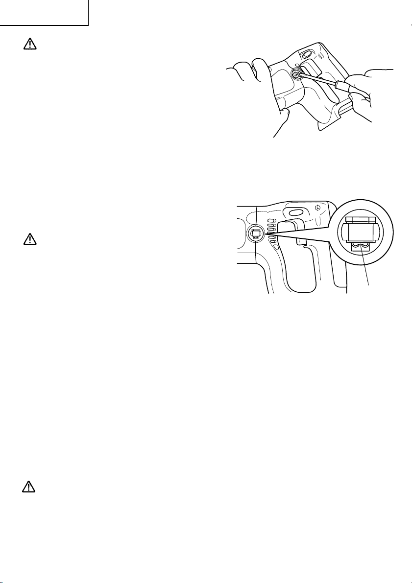
4. Confirm the direction of bit rotation (Fig. 7)
The bit rotates clockwise (viewed from the rear side) by pushing the R-side of the push
button. (Fig. 7-a)
The L-side of the push button is pushed to turn the bit counterclockwise. (Fig. 7-b)
The motor does not rotate if the push button is set to the center position. (Fig. 7-c)
CAUTION:
Always the push button is set to the center position when carrying or storing the tool.
Push the
side
L
Push
button
Push
Push the
side
R
button
(a) Forward rotation (b) Reverse rotation (c) Does not rotate
Fig. 7 Diagram seen from the handle side
5. Installing the side handle and handle
joint (Fig. 8)
A side handle and handle joint are supplied
with the hammer drill.
They can be installed on either side of the
tool for right or left handed use.
To install the side handle and handle joint,
thread it into the socket on the desired side of
the tool and tighten it securely.
Loosen
Handle
joint
Fig. 8
Tighten
Loosen
Push
button
Center
position
Side
handle
Tighten
18
Page 19

English
6. HAMMER to ROTATION changeover
(Fig. 9)
The Hammer Drill can be switched from
HAMMER (hammer plus rotation) to ROTATION (rotation only) by turning the change
lever. When boring concrete, stone, tile or
similar hard materials, turning the change
lever to HAMMER side. The drill head hammers against the material while continuing
to rotate.
When boring metal, wood or plastic, turning
the change lever to ROTATION side. The
hammer drill can be used as an ordinary
electric drill.
CAUTION:
Do not use the Hammer Drill in the HAMMER function if the material can be bored by
rotation only. Such action will not only reduce drill efficiency, but may also damage the
drill tip.
NOTE
The change lever may not turn smoothly when changing from hammer drill mode to drill
mode. (Fig. 9)
In this case, operate the machine for few seconds.
The spindle shaft will then be pushed forward, and the change lever can be moved
smoothly.
Change
lever
Hammer Rotation
Fig. 9
7. High-speed/Low-speed changeover (Fig.
10)
Prior to changing speed, ensure that the
hammer drill has come to a complete stop.
To change speed, depress the shift lock and
slide in to the appropriate direction, as indicated by the arrow in Fig. 10. The numeral "1"
engraved in the hammer drill body denotes
low speed, the numeral "2" denotes high
speed.
CAUTION:
When changing the rotational speed with the shift lock, confirm that the switch is off.
Changing the speed while the motor is rotating will damage the gears.
Shift lock (Push and slide)
Fig. 10
19
Page 20

English
8. Attaching the angle unit. (Optional accessory)
(1) Removing keyless chuck from hammer drill
(Fig. 11)
䡬 To remove the keyless chuck from the ham-
mer drill, open the keyless chuck jaws as far
as possible and turn out the locking screw
(left hand thread). This screw locks the keyless chuck to the spindle. Install the hex. bar
wrench into the keyless chuck. Place the
accessory wrench in the hexagonal opening
of the angle unit spindle. Tightly restrain the
hammer drill on a firm base. Turn the keyless
chuck until the wrench is at about a 30° angle
to the bench top and strike the wrench sharply
with a hammer so the keyless chuck turns in
the counterclockwise direction (viewed from
the front side). This should loosen the keyless chuck from the spindle which has a right
hand thread and you will be able to remove
the keyless chuck by hand.
CAUTION:
If the keyless chuck cannot be removed by striking the wrench, don’t strike the wrench
forcibly and send the hammer drill to a HITACHI AUTHORIZED SERVICE CENTER.
Hex. bar
wrench
Locking screw
Loosen
Fig. 11
(2) Attaching the angle unit.
䡬
After removing the keyless chuck, rotate the
change letter to ROTATION side. Engage the
coupling to the hammer drill spindle, fit the
joint sleeve to the gear cover, attach the angle
unit to the other end of the joint sleeve, and
turn the angle unit slightly in either direction
so the hex. hole in the coupling engages the
hex. portion of the angle unit spindle. Adjust
the direction of the angle unit and tighten the
joint sleeve by clamping bolts.
Tighten two clamping bolts equally and
gradually in turn with a torque of 61-70 lnlbs. (70-80kgf·cm) (extent of force which can
be subjected by only a wrist with the open
end wrench provided to tight clamping bolts.).
(Fig. 12)
䡬 To operate the angle unit at low speed, at-
tach the keyless chuck to the angle unit spindle
at the side marked “LOW” and secure the
locking screw. At this setting, the drilling
speed is decreased to about 70% and the
drilling torque is increased to about 150%.
(Fig. 13)
20
Angle
unit
Clamping bolt
Joint
sleeve
Fig. 12
Low
speed
High speed
Fig. 13
Coupling
Page 21

English
䡬 To operate the angle unit at high speed,
attach the keyless chuck to the angle unit
spindle at the side marked “HIGH” and secure the locking screw. At this setting, the
drilling speed is increased to about 150% and
the drilling torque is decreased to about 70%.
(Fig. 13)
(3) Installing the side handle and handle joint
(Fig. 14)
The side handle and handle joint can be
installed on either side of the angle unit for
right or left handed use. To install the side
handle and handle joint, thread it into the
socket on the desired side of the angle unit
and tighten it securely.
(4) Removing keyless chuck from angle unit
䡬 The keyless chuck can be removed from angle unit in the same manner it was removed
from the impact drill; however, ALWAYS REMOVE ANGLE UNIT FROM THE HAMMER
DRILL BEFORE ATTEMPTING TO LOOSEN KEYLESS CHUCK. This will prevent damage
of hammer drill’s gear. Use open end wrench provided to hold angle unit spindle before
attempting to loosen keyless chuck.
CAUTION:
If the keyless chuck cannot be removed by striking the wrench, don’t strike the wrench
forcibly and send the hammer drill to a HITACHI AUTHORIZED SERVICE CENTER.
Side handle
Fig. 14
HOW TO USE
1. Switch operation
䡬 When the switch trigger is depressed, the tool rotates. When the switch trigger is
released, the tool stops.
䡬 The rotational speed of the hammer drill can be controlled by varying the amount that
the switch trigger is pulled. Speed is low when the switch trigger is pulled slightly and
increases as the switch trigger is pulled more.
䡬 When releasing the switch trigger, the brake will be applied for immediate stopping.
2. When using as a Drill or an Hammer Drill
(1) Pressing force of the hammer drill
You cannot drill holes more quickly even if you press the hammer drill with a stronger
force than necessary. It not only damages tip of drill bit and decreases the efficiency of
operation, but also shortens the life of the drill tip.
(2) In case of penetrating holes
Drill bits can be broken when the material being drilled is penetrated. It is important to
decrease pressing force just before penetrating.
21
Page 22

English
WARNING
The hammer drill operates with high torque.
The larger the drill bit diameter, the larger the reactive force on your arm.
Be careful not to lose control of the hammer drill because of this reactive force.
To maintain firm control, establish a good foothold, use the side handle and handle joint,
hold the hammer drill tightly with both hands, and ensure that the hammer drill is
vertical to the material being drilled.
CAUTION
● Motor may be installed when in proper drill bit is used. If the motor is locked, turn off
the switch immediately.
● In continuous operation, conduct no-load operation for five seconds after completing a
drilling job.
22
Page 23

English
MAINTENANCE AND INSPECTION
WARNING: Be sure to turn off the switch and remove the battery before maintenance
and inspection.
1. Inspecting the drill bits
Since use of a dull tool will cause motor malfunctioning and degraded efficiency, replace
the drill bit with a new one or resharpening without delay when abrasion is noted.
2. Inspecting the screws
Regularly inspect all screws and ensure that they are fully tightened. Should any of the
screws be loosened, retighten them immediately.
WARNING: Using this drill with loosened screws is extremely dangerous.
3. Maintenance of the motor
The motor unit winding is the very “heart”’ of the power tool. Exercise due care to ensure
the winding does not become damaged and/or wet with oil or water.
4. Inspecting the carbon brushes (Fig. 15)
The motor employs carbon brushes which
are consumable parts. Since and excessively
worn carbon brush can result in motor
trouble, replace the carbon brush with new
ones when it becomes worn to or near the
“wear limit”. In addition, always keep carbon
brushes clean and ensure that they slide
freely within the brush holders.
NOTE:
When replacing the carbon brush with a new
one, be sure to use the Hitachi Carbon Brush
Code No. 999058.
Wear limit
0.12" (3 mm)
0.45"
(11.5 mm)
Fig. 15
5. Replacing carbon brushes
Take out the carbon brush by first removing
the brush cap and then hooking the protrusion
of the carbon brush with a slotted-head screw
driver, etc., as shown in Fig. 16, Fig. 17.
When installing the carbon brush, choose
the direction so that the nail of the carbon
brush (Fig. 16) agrees with the contact portion
outside the brush tube (Fig. 18). Then push it
in with a finger.
Lastly, install the brush cap.
Nail of
carbon brush
Protrusion of
carbon brush
Fig. 16
23
Page 24
English
CAUTION:
Be absolutely sure to insert the nail of the
carbon brush into the contact portion outside the brush tube. (You can insert whichever one of the two nails provided.)
Caution must be exercised since any error in
this operation can result in the deformed
nail of the carbon brush and may cause
motor trouble at an early stage.
6. Check for Dust
Dust may be removed with a soft cloth or a
cloth dampened with soapy water.
Do not use bleach, chlorine, gasoline or thinner, for they may damage the plastics.
Fig. 17
7. Disposal of the exhausted battery
WARNING:
Do not dispose of the exhausted battery.
The battery must explode if it is incinerated.
The product that you have purchased contains a rechargeable battery. The battery is
recyclable. At the end of it’s useful life, under
various state and local laws, it may be illegal
to dispose of this battery into the municipal
waste stream. Check with your local solid
waste officials for details in your area for
recycling options or proper disposal.
Fig. 18
8. Storage
Storing in a place below 104°F (40°C) and out of the reach of children.
9. Service and repairs
All quality power tools will eventually require servicing or replacement of parts because
of wear from normal use. To assure that only authorized replacement parts will be used,
all service and repairs must be performed by a HITACHI AUTHORIZED SERVICE CENTER,
ONLY.
Contact portion
outside brush
tube
10.Service parts list
CAUTION: Repair, modification and inspection of Hitachi Power Tools must be carried
out by an Hitachi Authorized Service Center.
This Parts List will be helpful if presented with the tool to the Hitachi
Authorized Service Center when requesting repair or other maintenance. In
the operation and maintenance of power tools, the safety regulations and
standards prescribed in each country must be observed.
24
Page 25

English
MODIFICATIONS:
Hitachi Power Tools are constantly being improved and modified to incorporate the latest
technological advancements.
Accordingly, some parts (i.e. code numbers and/or design) may be changed without prior
notice.
25
Page 26

English
ACCESSORIES
WARNING: ALWAYS use Only authorized HITACHI replacement parts and accesso-
ries. NEVER use replacement parts or accessories which are not intended for use with this tool. Contact HITACHI if you are not sure
whether it is safe to use a particular replacement part or accessory with
your tool.
The use of any other attachment or accessory can be dangerous and
could cause injury or mechanical damage.
NOTE:
Accessories are subject to change without any obligation on the part of the HITACHI.
STANDARD ACCESSORIES
DV24DV
1 Charger (UC24YFB) ........................................................... 1
2 Plastic case (Code No. 319815) ........................................ 1
3 Side handle (Code No. 981205) ....................................... 1
4 Handle joint (Code No. 319791) ....................................... 1
OPTIONAL ACCESSORIES.....sold separately
1. Battery (EB2420)
21
3
4
26
Page 27

2. Angle unit (Code No. 319528)
For use in drilling holes in narrow spaces
(1) Drill bit for concrete and brick
English
Bit Dia. Overall Code No. Bit Dia. Overall Code No. Bit Dia. Overall Code No.
1/8" 2-9/16" 939875 5/16" 4" 931852 9/16" 6-5/16" 931776
(3.2mm) (65mm) (8mm) (100mm) (14.3mm) (160mm)
3/16" 3-3/8" 939879 3/8" 4-3/4" 931854 5/8" 6-5/16" 931670
(4.8mm) (85mm) (10mm) (120mm) (16mm) (160mm)
7/32" 4" 939882 15/32" 4-3/4" 971704 3/4" 6-5/8" 959615
(5.5mm) (100mm) (12mm) (120mm) (20mm) (170mm)
1/4" 4" 939884 1/2" 6-5/16" 931855
(6.4mm) (100mm) (13mm) (160mm)
Length Length Length
NOTE
Specifications are subject to change without any obligaiton on the part of the HITACHI.
27
Page 28

Français
INFORMATIONS IMPORTANTES DE SÉCURITÉ
Lire et comprendre toutes les précautions de sécurité, les avertissements et les instructions
de fonctionnement dans ce mode d’emploi avant d’utiliser ou d’entretenir cet outil motorisé.
La plupart des accidents causés lors de l’utilisation ou de l’entretien de l’outil motorisé
proviennent d’un non respect des règles ou précautions de base de sécurité. Un accident
peut la plupart du temps être évité si l’on reconnaît une situation de danger potentiel avant
qu’elle ne se produise, et en observant les procédures de sécurité appropriées.
Les précautions de base de sécurité sont mises en évidence dans la section “SECURITE” de
ce mode d’emploi et dans les sections qui contiennent les instructions de fonctionnement
et d’entretien.
Les dangers qui doivent être évités pour prévenir des blessures corporelles ou un
endommagement de la machine sont identifiés par AVERTISSEMENTS sur l’outil motorisé
et dans ce mode d’emploi.
NE JAMAIS utiliser cet outil motorisé d’une manière qui n’est pas spécifiquement
recommandée par HITACHI.
SIGNIFICATION DES MOTS D’AVERTISSEMENT
AVERTISSEMENT indique des situations potentiellement dangereuses qui, si elles sont
ignorées, pourraient entraîner la mort ou de sérieuses blessures.
PRECAUTION indique des situations dangereuses potentilles qui, si elles ne sont pas
évitées, peuvent entraîner de mineures et légères blessures ou endommager la machine.
REMARQUE met en relief des informations essentielles.
28
Page 29

Français
SECURITE
REGLES GENERALE DE SECURITE – POUR TOUS LES OUTILS
FONCTIONNANT SUR BATTERIE
AVERTISSEMENT:Lire et coxmprendre toutes les instructions.
Un non respect de toutes les instructions ci-dessous peut
entraîner une électrocution, un incendie et/ou de sérieuses
blessures personnelles.
CONSERVER CES INSTRUCTIONS
1. Zone de travail
(1) Garder la zone de travail propre et bien éclairée. Les établis mal rangés et les zones
sombres invitent aux accidents.
(2) Ne pas utiliser les outils motorisés dans une atmosphère explosive, telle qu’en
présence de liquides inflammables, de gaz ou de poussières. Les outils motorisés
créent des étincelles qui risquent d’enflammer la poussière ou les vapeurs.
(3) Tenir les spectateurs, les enfants et les visiteurs éloignés, lors de l’utilisation de
l’outil motorisé. Une distraction peut faire perdre le contrôle de la machine.
2. Sécurité électrique
(1) Un outil motorisé à batterie avec batterie intégrée ou batterie séparée ne devra être
rechargé qu’avec le chargeur spécialement conçu pour la batterie. Un chargeur qui
convient pour un type de batterie donné peut présenter un risque de feu s’il est utilisé
avec une autre batterie.
(2) Utiliser l’outil motorisé à batterie exclusivement avec la batterie spécialement
conçue. L’utilisation de toute autre batterie peut présenter un risque de feu.
3. Sécurité personnelle
(1) Rester sur ses gardes, regarder ce que l’on fait et utiliser son sens commun lors de
l’utilisation d’un outil motorisé. Ne pas utiliser un outil en état de fatigue ou sous
l’influence de drogues, d’alcool ou de médicaments. Un moment d’inattention lors de
l’utilisation de l’outil motorisé peut entraîner de sérieuses blessures personnelles.
(2) S’habiller correctement. Ne pas porter des vêtements larges ou des bijoux. Attacher
les cheveux longs. Tenir ses cheveux, vêtements et ses gants éloignés des parties
mobiles. Les vêtements larges, les bijoux et les cheveux longs peuvent se prendre
dans les parties mobiles.
(3) Eviter tout démarrage accidentel. S’assurer que le l’interrupteur d’alimentation est
sur la position d’arrêt avant d'insérer la batterie. Transporter l’appareil avec les
doigts sur l’interrupteur d’alimentation ou la batterie insérée dan un outil avec
l’interrupteur sur la position marche invite aux accidents.
(4) Retirer les clefs d’ajustement ou les commutateurs avant de mettre l’outil sous
tension. Une clef qui est laissée attachée à une partie tournante de l’outil peut
provoquer une blessure personnelle.
(5) Ne pas trop présumer de ses forces. Garder en permanence une position et un
équilibre correct. Une position et un équilibre correct permettent un meilleur contrôle
de l’outil dans des situations inattendues.
(6) Utiliser un équipement de sécurité. Toujours porter des lunettes de protection. Un
masque à poussière, des chaussures de sécurité antidérapantes, un chapeau dur et
des bouchons d’oreille doivent être utilisés dans les conditions appropriées.
29
Page 30

Français
4. Utilisation de l’outil et entretien
(1) Utiliser un étau ou toutes autres façons de fixer et maintenir la pièce à usiner sur une
plate-forme stable. Tenir la pièce avec la main ou contre son corps est instable et peut
conduire à une perte de contrôle de l’outil.
(2) Ne pas forcer sur l’outil. Utiliser l’outil correct pour l’application souhaitée. L’outil
correct réalisera un meilleur et plus sûr travail dans le domaine pour lequel il a été
conçu.
(3) Ne pas utiliser un outil s’il ne se met pas sous ou hors tension avec un interrupteur.
Un outil qui ne peut pas être commandé avec un interrupteur est dangereux et doit
être réparé.
(4) Débrancher la batterie de l’outil ou mettere l’interrupteur sur la position verrouillée
ou éteinte avant d’effectuer un réglage, de remplacer un accessoire ou de ranger
l’outil. Ces mesures de sécurité préventives réduiront les risques de déclenchement
accidentel de l’outil.
(5) Ranger les outils inutilisés hors de la portée des enfants et des autres personnes
inexpérimentées. Les outils sont dangereux dans les mains de personnes
inexpérimentées.
(6) Lorsqu’on ne se sert pas de la batterie, l’éloigner des objets métalliques, par exemple
trombones, pièces de monnaie, clous, vis, ou petits objets métalliques qui peuvent
créer une connexion entre deux bornes. Le fait de court-circuiter les bornes entre elles
peut provoquer des étincelles, des brulûres ou un feu.
(7) Conserver les outils avec soin. Garder les outils de coupe aiguisés et propres. Des
outils bien entretenus, avec des lames coupantes aiguisées risquent moins de se
gripper et sont plus faciles à contrôler.
(8) Vérifier les défauts d’alignement ou grippage des parties mobiles, les ruptures des
pièces et toutes les autres conditions qui peuvent affecter le fonctionnement des
outils. En cas de dommage, faire réparer l’outil avant de l’utiliser. Beaucoup
d’accidents sont causés par des outils mal entretenus.
(9) Utiliser uniquement les accessoires recommandés par le fabricant pour le modèle
utilisé. Des accessoires qui peuvent convenir à un outil, peuvent devenir dangereux
lorsqu’ils sont utilisés avec un autre outil.
5. Réparation
(1) La réparation de l’outil ne doit être réalisée uniquement par un réparateur qualifié.
Une réparation ou un entretien réalisé par un personnel non qualifié peut entraîner
des risques de blessures.
(2) Lors de la réparation d’un outil, utiliser uniquement des pièces de rechange identiques.
Suivre les instructions de la section d’entretien de ce mode d’emploi. L’utilisation de
pièces non autorisées ou un non respect des instructions d’entretien peut créer un
risque d’électrocution ou de blessures.
AVERTISSEMENT:
La poussière résultant d’un ponçage, d’un sciage, d’un meulage, d’un perçage ou de toute
autre activité de construction renferme des produits chimiques qui sont connus par l’Etat
de Californie pour causer des cancers, des défauts de naissance et autres anomalies de
reproduction. Nous énumérons ci-dessus certains de ces produits chimiques:
● Plomb des peintres à base de plomb,
● Silice cristalline des briques et du ciment et autres matériaux de maçonnerie, et
● Arsenic et chrome du bois d’oeuvre traité chimiquement.
Le risque d’exposition à ces substances varie en fonction de la fréquence d’exécution
de ce genre de travail. Pour réduire l’exposition à ces produits chimiques, travailier dans
un lieu bien ventilé, et porter un équipement de protection agréé, par exemple un
masque anti-poussière spécialement conçu pour filter les particules microscopiques.
30
Page 31

Français
REGLES DE SECURITE SPECIFIQUES ET SYMBOLES
1. Tenir les outils par les surfaces de grippage lors de la réalisation d’opération où l’outil
de coupe risque d’entrer en contact avec des câbles cachés. Un contact avec un fil “sous
tension” mettra les parties métalliques de l’outil “sous tension” et électrocutera
l’utilisateur.
2. TOUJOURS porter des bouchons d’oreille lors de l’utilisation de l’outil pendant de
longues périodes.
Une exposition prolongée à un son de forte intensité peut endommager
l’ouïe de l’utilisateur.
3. NE JAMAIS toucher la mèche avec des mains nues après l’utilisation.
4. NE JAMAIS porter de gants faits d’une matière qui risque de s’enrouler, comme du
coton, de la laine, de la toile ou de la ficelle, etc.
5. TOUJOURS fixer la poignée latérale avec le joint de poignée et tenir fermement la
perceuse.
6. NE JAMAIS toucher les parties mobiles.
NE JAMAIS placer ses mains, ses doigts ou toute autre partie de son corps près des
parties mobiles de l’outil.
7. NE JAMAIS utiliser l’outil sans que tous les dispositifs de sécurité ne soient en place.
NE JAMAIS faire fonctionner cet outil sans que tous les dispositifs et caractéristiques de
sécurité ne soient en place et en état de fonctionnement. Si un entretien ou une
réparation nécessite le retrait d’un dispositif ou d’une caractéristique de sécurité,
s’assurer de bien remettre en place le dispositif ou la caractéristique de sécurité avant
de recommencer à utiliser l’outil.
8. Utiliser l’outil correct
Ne pas forcer sur un petit outil ou accessoire pour faire le travail d’un outil de grande
puissance. Ne pas utiliser un outil pour un usage pour lequel il n’a pas été prévu: par
exemple, ne pas utiliser une scie circulaire pour couper des branches d’arbre ou des
bûches.
9. NE JAMAIS utiliser un outil motorisé pour des applications autres que celles spécifiées.
NE JAMAIS utiliser un outil motorisé pour des applications autres que celles spécifiées
dans le mode d’emploi.
10. Manipuler l’outil correctement
Utiliser l’outil de la façon indiquée dans ce mode d’emploi. Ne pas laisser tomber ou
lancer l’outil. NE JAMAIS permettre que l’outil soit utilisé par des enfants, des personnes
non familiarisées avec son fonctionnement ou un personnel non autorisé.
11. Maintenir toutes les vis, tous les boulons et les couvercles fermement en place.
Maintenir toutes les vis, tous les boulons et les couvercles fermement montés. Vérifier
leurs conditions périodiquement.
31
Page 32

Français
12. Ne pas utiliser les outils motorisés si le revêtement de plastique ou la poignée est fendu.
Des fentes dans le revêtement ou la poignée peuvent entraîner une électrocution. De tels
outils ne doivent pas être utilisés avant d’être réparé.
13. Les lames et les accessoires doivent être fermement montés sur l’outil.
Eviter les blessures potentielles personnelles et aux autres. Les lames, les instruments
de coupe et les accessoires qui ont été montés sur l’outil doivent être fixés et serrés
fermement.
14. Garder propres les évents d’air du moteur
Les évents d’air du moteur doivent être maintenus propres de façon que l’air puisse
circuler librement tout le temps. Vérifier les accumulations de poussière fréquemment.
15. NE JAMAIS utiliser un outil défectueux ou qui fonctionne anormalement.
Si l’outil n’a pas l’air de fonctionner normalement, fait des bruits étranges ou sans cela
paraît défectueux, arrêter de l’utiliser immédiatement et le faire réparer par un centre de
service Hitachi autorisé.
16. NE JAMAIS laisser fonctionner l’outil sans surveillance. Le mettre hors tension.
Ne pas abandonner l’outil avant qu’il ne soit complètement arrêté.
17. Manipuler l’outil motorisé avec précaution.
Si un outil motorisé tombe ou frappe un matériau dur accidentellement, il risque d’être
déformé, fendu ou endommagé.
18. Ne pas essuyer les parties en plastique avec du solvant.
Les solvants comme l’essence, les diluants, la benzine, le tétrachlorure de carbone et
l’alcool peuvent endommager et fissurer les parties en plastique. Ne pas les essuyer
avec de tels solvants.
Essuyer les parties en plastique avec un chiffon doux légèrement imbibé d’une solution
d’eau savonneuse et sécher minutieusement.
19. TOUJOURS porter des lunettes de protection qui respectent les dernières révisions du
Standard ANSI Z87.1.
20. Définitions pour les symboles utilisés sur cet outil
V ............. volts
--- ............ courant continu
no ............ vitesse à vide
---/min .... rotations ou mouvements de va-et-vient
32
Page 33

Français
CONSIGNES DE SÉCURITÉ IMPORTANTES POUR LE CHARGEUR DE
BATTERIE
AVERTISSEMENT: Une utilisation incorrecte ou dangereuse das outils électriques
peut entraîner la mort ou des blessures graves.
LIRE TOUT CE MODE D’EMPLOI.
1. Ce manuel renferme des consignes de sécurité et d’utilisation importantes pour le
chargeur de batterie modèle UC24YFB.
2. Avant d’utiliser le chargeur de batterie, lire toutes les étiquettes d’instruction et de
précaution apposées sur (1) le chargeur de batterie, (2) la batterie, et (3) le produit utilisant
la batterie.
3. Pour réduire tout risque de blessure, NE recharger QUE les batteries rechargeables
HITACHI utilisées dans le modèle EB2420. Les autres types de batterie pourraient
exploser et provoquer des blessures ou des dommages.
4. Ne pas exposer le chargeur à la pluie ni à la neige.
5. L’utilisation d’un accessoire non recommandé ou non vendu par le fabricant du chargeur
de batterie risque de provoquer un feu, une décharge électrique ou des blessures.
6. Pour réduire tout risque de dommage de la fiche et du cordon électrique, débrancher le
cordon du chargeur en tirant sur la fiche.
7. Vérifier que le cordon est placé de façon que personne ne puisse marcher dessus, se
prendre les pieds dedans, ni l’endommager ou le soumettre à des contraintes.
8. Ne pas utiliser de cordon de rallonge si cela n’est pas absolument nécessaire. L’utilisation
d’un cordon de rallonge incorrect pourrait entraîner un feu ou une décharge électrique.
Si l’on doit utiliser un cordon de rallonge, s’assurer que :
a. Les broches de la rallonge ont les mêmes numéro, taille et forme que celles de la fiche
du chargeur ;
b. Le cordon de rallonge est correctement raccordé et en bon état électrique ;
c. Le calibre du fil doit être au moins suffisant pour l’intensité nominale CA (ampères)
du chargeur de batterie spécifiées dans le tableau ci-dessous.
TABLEAU 1
CALIBRE MINIMUM RECOMMANDÉ POUR LES CORDONS DE RALLONGE
DES CHARGEURS DE BATTERIE
Intensité nominale d’entrée CA (ampères)*
Egal ou mais non Longueur de cordon en pieds (mètres)
supérieur à inférieur à 25 (7.5) 50 (15) 100 (30) 150 (45)
0 2 18 18 18 16
2 3 18 18 16 14
3 4 18 18 16 14
Calibre du cordon
* Si l’intensité nominale d’entrée du chargeur de batterie est donnée en watts et non en
ampères, calculer la capacité en ampères correspondante en divisant la capacité en
ampères par la capacité de tension, par exemple :
1250 watts
125 volts
= 10 ampères
33
Page 34

Français
9. Ne pas utiliser le chargeur si son cordon ou sa fiche sont endommagés - Le remplacer
immédiatement.
10. Ne pas utiliser le chargeur s’il a reçu un coup, s’il est tombé ou endommagé de toute
autre manière. L’apporter à un réparateur qualifié.
11. Ne pas démonter le chargeur ni le produit qui reçoit la batterie ; si un entretien ou des
réparations sont nécessaires, les apporter à un réparateur qualifié. Un remontage
incorrect pourrait provoquer une décharge électrique ou un feu.
12. Pour réduire tout risque de décharge électrique, débrancher le chargeur de la prise
secteur avant tout entretien ou nettoyage. Il ne suffit pas de sortir la batterie.
13. Ce chargeur de batterie pourra être fixé comme accessoire standard sur les outils
HITACHI alimentés sur batterie. Dans ce cas, vérifier le mode d'emploi de l'outil HITACHI
alimenté sur batterie avant d'utiliser le chargeur de batterie.
CONSIGNES DE SÉCURITÉ IMPORTANTES POUR L’UTILISATION
DE LA BATTERIE ET DU CHARGEUR DE BATTERIE
Pour pouvoir utiliser la marteau perforateur à batterie, il faudra recharger la batterie. Avant
d’utiliser le chargeur de batterie modèle UC24YFB, bien lire attentivement toutes les
consignes et les avertissements signalés sur le chargeur, sur la batterie ou dans ce manuel.
BIEN NOTER : UTILISER EXCLUSIVEMENT DES BATTERIES HITACHI DES EB2420. LES
AUTRES TYPES DE BATTERIE POURRAIENT EXPLOSER OU PROVOQUER DES
BLESSURES.
Pour éviter tout risque de blessure, observer les consignes suivantes :
AVERTISSEMENT: Une utilisation incorrecte de la batterie ou du chargeur de
batterie risque de provoquer des blessures. Pour éviter tout
risque de blessure :
1. NE JAMAIS démonter la batterie.
2. NE JAMAIS jeter la batterie au feu, même si elle est endommagée ou complètement
usée. La batterie risque d’exploser au feu.
3. NE JAMAIS court-circuiter la batterie.
4. NE JAMAIS insérer d’objets dans les ouïes d’aération du chargeur. Il pourrait en
résulter un choc électrique ou des dommages du chargeur.
5. NE JAMAIS effectuer la recharge à l’extérieur. Eloigner la batterie des rayons directs
du soleil et utiliser exclusivement dans des endroits à faible humidité et
bien aérés.
6. NE JAMAIS effectuer la recharge si la température est inférieure à 0°C (32°F) ou
supérieure à 40°C (104°F).
7. NE JAMAIS raccorder deux chargeurs de batterie ensemble.
8. NE JAMAIS insérer de corps étrangers dans l’orifice de la batterie ou du chargeur de
batterie.
9. NE JAMAIS utiliser de transformateur-élévateur pour la recharge.
34
Page 35

Français
10. NE JAMAIS utiliser de générateur de moteur ni d’alimentation CC pour la recharge.
11. NE JAMAIS ranger la batterie ni le chargeur de batterie dans un lieu où la température
peut atteindre ou dépasser 40°C (104°F).
12. TOUJOURS alimenter le chargeur sur une prise secteur domestique standard (120
volts). L’utilisation du chargeur à une autre tension peut entraîner une
surchauffe et endommager le chargeur.
13. TOUJOURS attendre au moins 15 minutes entre deux recharges pour éviter toute
surchauffe du chargeur.
14. TOUJOURS débrancher le cordon d’alimentation de la prise secteur lorsqu’on ne se
sert pas du chargeur.
CONSERVER CES INSTRUCTIONS
ET
LES METTRE A LA DISPOSITION
DES AUTRES UTILISATEURS
ET
PROPRIETAIRES DE CET OUTIL!
35
Page 36

Français
DESCRIPTION FONCTIONNELLE
REMARQUE:
Les informations contenues dans ce mode d’emploi sont conçues pour assister l’utilisateur
dans une utilisation sans danger et un entretien de l’outil motorisé.
NE JAMAIS utiliser ni entreprendre une révision de l’outil sans avoir d’abord lu et
compris toutes les instructions de sécurité contenues dans ce manuel.
Certaines illustrations dans ce mode d’emploi peuvent montrer des détails ou des
accessoires différents de ceux de l’outil motorisé utilisé.
MODELE
DV24DV (BFK): avec chargeur et coffret.
NOM DES PARTIES
1. Marteau perforateur à batterie (DV24DV)
Mandrin sans
clavette
Pièce de blocage
coulissante
䡬 Batterie (EB2420)
36
Levier de
changement
Poignée latelale
Taquet
Plaque signalétique
Fig. 1
Boîtier
Orifice de prise
Poussoir
Gâchette de
interrupteur
Poignée
Batterie
Page 37

2. Chargeur de batterie (UC24YFB)
Lampe témoin
Plaque de
précaution
SPECIFICATIONS
1. Marteau perforateur à batterie (DV24DV)
Français
Rail de guidage
Plaque signalétique
Fig. 2
Moteur Moteur CC
Changement de vitesse
Vitesse à vide
Capacité
Capacité de mandrin 1/2" (13 mm)
Batterie (EB2420) Batterie au nickel-cadmium
Poids 8,8 lbs (4,0 kg)
Béton
Mèche creuse 1-1/2" (38 mm) 3/4" (20 mm)
Bois
Foret à lame plate 1-1/4" (32 mm)
Foret à avance automatique
Foret hélicoîdal 1/2" (13 mm) 5/16" (8 mm)
Acier
Scie circulaire 1-1/2" (38 mm)
1:Faible 2:Grande
0–400/min 0–1750/min
3/4" (20 mm) 3/8" (10 mm)
2-9/16" (65 mm) 1-1/4" (32 mm)
Tension
Fréquence de recharge et de décharge
...............................................
............................
CC 24 V
environ 1000
37
Page 38

Français
<Capacité avec angle (accessoire en option)>
Vitesse de DV24DV
Vitesse de
Bois Mèche creuse 1/1/2" (38mm) 1" (25mm) 3/4" (20mm)
Acier
l’angle
Foret à lame plate
Foret à avance 2-9/16" (65mm)
automatique
Foret hélicoîdal
Scie circulaire 1-1/2" (38mm) 1-3/8" (35mm)
1:Faible 2:Grande
Faible (270/min) Grande (580/min) Faible (1200/min) Grande (2560/min)
1-1/2" (38mm) 1-1/4" (32mm) 3/4" (20mm)
1-1/2" (38mm) 1-1/4" (32mm)
1/2" (13mm) 1/2" (13mm) 3/8" (10mm) 1/4" (6,4mm)
2. Chargeur de batterie (UC24YFB)
Source d’alimentation d’entrée Monophasée : CA 120 V 60 Hz
Durée de recharge Environ 50 mn (à une température de 68°F (20°C))
Chargeur
Poids 1,3 lbs (0,6 kg)
Tension de charge ................................ CC 24 V
Courant de charge .............................. CC 2,5 A
38
Page 39

Français
ASSEMBLAGE ET FONCTIONNEMENT
UTILISATIONS
䡬 Action combinée de ROTATION et MARTEAU:
Perçage de trous dans surfaces dures (béton, briques, granìte, etc.).
䡬 Par action de ROTATION:
Perçage de trous dans acier, bois et matières plastiques.
MÉTHODE DE RETRAIT ET D’INSTALLATION DE LA BATTERIE
1. Retrait de la batterie
Maintenir fermement la poignée et pousser les taquets de la batterie pour l’enlever. (Voir
Fig. 3 et 4).
2. Mise en place de la batterie
Insérer la batterie en alignant le rail de guidage de la batterie sur celui du corps. Bien
s’assurer que la batterie est solidement fixée (Voir Fig. 4)
Taquet
Rail guide de la batterie
Batterie rechargeable
Poignée
Rail guide du
boîtier
Fig. 3
Tirer vers
l‘extérieur
MÉTHODE DE RECHARGE
REMARQUE:
Avant de brancher le chargeur dans la prise, vérifier les points suivants:
䡬 La tension de la source d’alimentation est indiquée sur la plaque signalétique.
䡬 Le cordon n’est pas endommagé.
AVERTISSEMENT:
Ne pas effectuer de recharge à une tension supérieure à la tension
indiquée sur la plaque signalétique. Cela brûlerait le chargeur.
Insérer
Fig. 4
1. Brancher la fiche du chargeur de batterie dans la prise.
Quand la fiche du chargeur de batterie est branchée dans la prise, le voyant de recharge
clignote lentement en rouge. (A intervalles d’une seconde)
AVERTISSEMENT:
Ne pas utiliser le cordon électrique s’il est endommagé. Le faire réparer
immédiatement.
39
Page 40

Français
2. Insérer la batterie dans le chargeur de batterie.
Insérer la batterie dans le chargeur de batterie comme indiqué à la Fig. 5. S’assurer que
la batterie repose bien dans le chargeur de batterie.
Avant l’insertion Après l’insertion
Fig. 5
3. Recharge
䡬 Quand la batterie est raccordée au chargeur de batterie, la recharge commence et la
lampe témoin s’allume en rouge. (Voir le Tableau 2)
REMARQUE:
Si la lampe témoin clignote en rouge, débrancher la fiche de la prise et vérifier si la
batterie est insérée correctement.
䡬 Quand la batterie est rechargée à fond, la lampe témoin clignote lentement en rouge. (A
intervalles d’une seconde) (Voir le Tableau 2.)
Tableau 2
Indications de la lampe témoin
Avant la
recharge
Pendant la
recharge
Recharge
terminée
Recharge
impossible
Recharge
impossible
40
Clignote
(ROUGE)
S’allume
(ROUGE)
Clignote
(ROUGE)
Scintille
(ROUGE)
S’allume
(VERTE)
S’allume pendant 0,5 seconde.
Ne s’allume pas pendant 0,5 seconde.
(Eteint pendant 0,5 seconde)
S’allume sans interruption
S’allume pendant 0,5 seconde.
Ne s’allume pas pendant 0,5 seconde.
(Eteint pendant 0,5 seconde)
S’allume pendant 0,1 seconde.
Ne s’allume pas pendant 0,1 seconde.
(Eteint pendant 0,1 seconde)
S’allume sans interruption
Anomalie de la batterie ou du
chargeur
La température de la batterie est
élevée et la recharge est impossible.
Page 41

Français
䡬 Température admissible d’une batterie rechargeable
La température admissible des batteries rechargeables est indiquée dans le tableau cidessous, et les batteries qui ont chauffé devront être laissées à refroidir pendant quelque
temps avant de pouvoir être rechargées.
Tableau 3
Batteries rechargeables
EB2420
䡬 Durée de recharge
Le Tableau 4 montre le temps de recharge nécessaire en fonction du type de batterie.
Tableau 4 Temps de recharge (en minutes approx.) à 68°F (20°C)
Tension de la batterie (V)
24V EB2420 50min.
REMARQUE:
La durée de recharge peut varier en fonction de la température et de la tension de la
source d’alimentation.
Température à laquelle la batterie peut être rechargée
23°F — 140°F
(–5°C — 60°C)
Capacité de la batterie (Ah)
2,0 Ah
4. Débrancher le chargeur de batterie de la prise.
PRECAUTION:
Ne pas débrancher la fiche de la prise en tirant sur le cordon.
Pour éviter tout dommage lorsqu’on débranche la fiche de la prise, bien tenir la fiche
proprement dite.
5. Retirer la batterie du chargeur de batterie.
Sortir la batterie du chargeur tout en la soutenant de la main.
En ce qui concerne le courant de décharge d’une batterie neuve
Etant donnée que les substances chimiques internes sont restées inactives dans le cas
des batteries neuves ou des batteries qui sont restées longtemps inutilisées, le courant
de décharge risque d’être très faible lors des première et deuxième utilisations. Ce
phénomène est temporaire et le temps de recharge normal sera rétabli quand les
batteries auront été rechargées 2 ou 3 fois.
Comment prolonger la durée de vie des batteries
䡬 Recharger les batteries avant qu’elles ne soient complètement épuisées.
Quand la puissance de l’outil utilisé faiblit, l’éteindre et recharger la batterie. Si l’outil
continue d’être utilisé jusqu’à épuisement du courant électrique, la batterie risque d’être
endommagée et sa durée de vie se raccourcira.
41
Page 42

Français
䡬 Eviter d’effectuer la recharge sous des températures élevées.
Une batterie est toujours chaude immédiatement après son utilisation. Si la batterie est
rechargée immédiatement après utilisation, les substances chimiques internes risquent
de se détériorer et la durée de vie de la batterie se raccourcira. Laisser la batterie refroidir
un moment avant de l’utiliser.
PRECAUTION:
● Si le chargeur a fonctionné pendant longtemps de suite, il sera chaud, ce qui risque de
provoquer des pannes. Lorsque la recharge est terminée, laisser le chargeur refroidir
pendant environ 15 secondes avant de passer à la recharge suivante.
● Si l’on recharge la batterie lorsqu’elle est chaude, soit parce qu’elle vient de fonctionner,
soit parce qu’elle est en plein soleil, il se peut que la lampe témoin s’allume en vert.
La batterie ne se rechargera pas. Dans ce cas, laisser la batterie refroidir avant de la
recharger.
AVANT L’UTILISATION
Vérifier l’aire de travail pour s’assurer qu’il n’y a ni débris ni désordre.
Evacuer toutes les personnes non nécessaires au travail. S’assurer que l’éclairage et la
ventilation sont satisfaisants.
AVANT LA MISE EN MARCHE
PRECAUTION:
Pour éviter tout risque d’accident, bien couper l’interrupteur et retirer la batterie lors de
l’installation ou du retrait des forets de perçage et autres pièces.
1. Pose et dépose du foret
(1) Pose du foret
Insérer le foret, etc. dans le mandrin sans
clavette.
Saisir fermement la bague et serrer le
manchon en le tournant vers la droite (dans
le sens des aiguilles d’une montre, vu de
l’avant). (Voir Fig. 6)
REMARQUE:
Si le manchon se relâche pendant le
fonctionnement, le serrer davantage .
La force de serrage sera plus forte si le
manchon est bien serré.
42
Manchon
Desserrer
Serrer
Anneau
Fig. 6
Page 43

Français
(2) Dépose du foret
Saisir fermement la bague et desserrer le manchon en le tournant vers la gauche (sens
inverse des aiguilles d’une montre vu de face). (Voir Fig. 6)
PRECAUTION:
Lorsqu’on monte un foret dans un mandrin sans clavette, bien serrer à fond. Si le
manchon n’est pas serré, le foret risque de glisser ou de tomber et de provoquer des
blessures.
2. Choix du foret de perçage correct
䡬 Pour perçage dans béton ou briques
Utiliser les forets spécifiés à la partie “Accessoires à option”.
䡬 Pour perçage dans métal ou plastique
Utiliser un foret de perçage ordinaire pour métal.
䡬 Pour perçage dans bois
Utiliser un foret de perçage ordinaire pour bois.
Toutefois, pour percer des trous de 1/4" (6,5 mm) ou plus petits, utiliser un foret de
perçage pour métal.
3. Vérifiez se la batterie a été correctement installée.
4. Verifiez la direction de rotation de la mèche (Fig. 7)
La mêche tourne dans le sens horaire (vu de l’arrière) quand on appuie sur côté-R du
levier de contact. (Fig. 7-a)
En appuyant sur côté-L du levier la mèche tourne dans le sens anti-horaire. (Fig. 7-b)
Le moteur ne tourne pas si le poussoir est placé sur la position médiane. (Fig. 7-c)
PRECAUTION:
Toujours s’assurer que le bouton-poussoir est à la position centrale avant de transporter
ou de ranger l’outil.
Pousser
sur le
R
Poussoir
(a) Rotation avant (b) Rotation arrière (c) Pas de rotation
côté
Fig. 7 Schéma vu du côté de la poignée
Pousser
sur le
côté
L
Poussoir
Poussoir
Position
médiane
43
Page 44

Français
5. Installation de la poignée latérale et du
joint de poignée (Fig. 8)
Une poignée latérale et un joint de poignée
sont fournis avec le marteau perforateur.
Ils se montent sur le côté gauche ou sur le
côté droit de l’outil, selon que l’on est gaucher
ou droitier.
Pour monter la poignée latérale et le joint de
poignée, les faire passer dans la douille sur le
côté voulu de l’outil et serrer la poignée à fond.
Desserrer
Joint de
poignée
Serrer
Desserrer
Fig. 8
6. Commutation: fonctionnement en
MARTEAU/fonctionnement en ROTATION (Fig. 9)
L
e marteau perforateur
de
MARTEAU (marteau
TION (rotation seulement) en tournant le levier
entièrement dans le sens des aiguilles d’une
montre. La tête de la perceuse percute contre le
matériau tout en continuant de tourner.
Lors du perçage de métal, de bois ou de
matières plastiques, ou pour le serrage de
vis, tourner le levier de changement à fond
dans le sens antihoraire. Le marteau
perforateur fonctionnera alors en tant que
perceuse électrique ordinaire.
PRECAUTION:
Ne pas utiliser le marteau perforateur pour la fonction MARTEAU si la pièce ne peut être
alésée que par rotation. Cela non seulement réduirait l’efficacité du perçage, mais
pourrait également endommager la pointe du foret de perçage.
peut être commutée
plus rotation) à ROTA-
Levier de
changement
Marteau Rotation
Fig. 9
Poignée
latérale
Serrer
NOTA
Lorsque l’on passe du mode de marteau perforateur au mode de perceuse (Fig. 9), il se
peut que le levier de changement ne tourne pas aisément. Dans ce cas, mettre l’outil en
marche et le faire fonctionner pendant quelques secondes.
La tige de l’axe est alors poussée vers l’avant, facilitant ainsi le déplacement du levier.
7. Commutation grande vitesse/faible
vitesse (Fig. 10)
Avant de changer de vitesse, s'assurer que le
marteau perforateur est complétement
arrêtée. Pour changer de vitesse, appuyer
sur la pièce de blocage et la faire coulisser
dans la bonne direction comme indiqué par
la flèche de la Fig. 10. Le numéro "1" gravé
sur le corps du marteau perforateur indique
la vitesse faible, le numéro "2" indique la
grande vitesse.
44
Pièce de blocage coulissante
(Pousser et faire coulisser)
Fig. 10
Page 45

Français
PRECAUTION:
Lors du changement de la vitesse de rotation avec le verrou de changement de vitesse,
vérifier que l’interrupteur est coupé. Le fait de changer la vitesse alors que le moteur
tourne endommagera les engrenages.
8. Fixation de l’angle (accessoire disponible
en option)
(1) Retrait du mandrin sans clavette du marteau
perforateur (Fig. 11)
䡬 Pour retirer le mandrin sans clavette du
marteau perforateur, ouvrir les mâchoires
du mandrin au maximum et tourner la vis de
verrouillage vers l’extérieur (filetage à
gauche). Cette vis verrouille le mandrin sans
clavette sur l’axe.
Installer la clé à barre hexagonale dans le
mandrin sans clavette. Placer la clé à 6 pans
fournie comme accessoire dans l’ouverture à
six pans de la broche du module d’angle. Tenir
fermement le
base solide. Tourner le mandrin sans clavette jusqu’à ce que la clé forme un angle d’environ
30° par rapport au dessus de l’établi, et frapper d’un grand coup sur la clé avec un marteau
de façon que le mandrin sans clavette tourne dans le sens inverse des aiguilles d’une montre
(vu de l’avant). Cela desserrera le mandrin sans clavette de l’axe avec filetage à droite, et il est
maintenant possible de retirer le mandrin à la main.
marteau perforateur
sur une
Cléf à six
pans
Vis de
verrouillage
Desserrer
Fig. 11
PRECAUTION:
Si l’on ne réussit pas à retirer le mandrin en le frappant avec la clé, ne pas frapper trop
fort avec la clé et envoyer le marteau à un SERVICE APRES-VENTE HITACHI AGREE.
(2) Fixation de l’angle
䡬 Après avoir retiré le mandrin sans clavette
tourner le levier de changement sur le côté
ROTATION. Emboîter le couplage sur l’axe
du marteau perforateur. Fixer le manchon du
raccord sur le cache du réducteur, fixer l’angle
à l’autre extrémité du manchon de raccord,
tourner légèrement l’angle dans l’un ou
l’autre sens de façon que l’orifice hexagonal
du couplage s’emboîte dans la section
hexagonale de l’angle, et serrer le manchon
de raccord à l’aide des boulons de serrage.
Serrer deux boulons de serrage de façon
uniforme et à tour de rôle au couple de 61–70 ln-lbs. (70-80 kgf·cm) (force égale à un
tour de poignet de la clé à fourche fournie
pour le serrage des boulons de serrage). (Fig.
12)
Unité de
perçage
d’angle
Manchon
de raccord Couplage
Boulon de
blocage
Fig. 12
45
Page 46

Français
䡬 Pour utiliser l’angle à faible vitesse, fixer le
mandrin sans clavette sur l’axe de l’angle en
face du repère latéral “LOW”, et fixer avec la
vis de verrouillage. A ce réglage, la vitesse de
perçage tombe à environ 70% et le couple de
perçage augmente jusqu’à environ 150%.
(Fig. 13)
䡬 Pour utiliser l’angle à grande vitesse, fixer le
mandrin sans clavette sur l’axe de l’angle en
face du repère latéral “HIGH”, et fixer avec la
vis de verrouillage. A ce réglage, la vitesse de
perçage augmente jusqu’à environ 150% et
le couple de perçage tombe à environ 70%.
(Fig. 13)
(3) Installation de la poignée latérale et du joint
de poignée (Fig. 14)
Une poignée latérale et le joint de poignée se
montent sur le côté gauche ou sur le côté
droit de l’angle, selon que l’on est gaucher
ou droitier. Pour monter la poignée latérale
et le joint de poignée, les faire passer dans la
douille sur le côté voulu de l’angle et serrer la
poignée à fond.
(4) Retrait du mandrin de l’angle
䡬 Le mandrin sans clavette se retire de l’angle de la même façon que de la perceuse à
percussion; toutefois, TOUJOURS RETIRER L’ANGLE DU MARTEAU PERFORATEUR
AVANT DE DESSERRER LE MANDRIN SANS CLAVETTE. Ceci évitera d’endommager les
engrenages du marteau perforateur. Tenir l’axe de l’angle avec la clé à fourche fournie
avant de desserrer le mandrin sans clavette.
Vitesse
élevée
Vitesse
ralentie
Fig. 13
Poignée latérale
Fig. 14
PRECAUTION:
Si l’on ne réussit pas à retirer le mandrin en le frappant avec la clé, ne pas frapper trop
fort avec la clé et envoyer le marteau à un SERVICE APRES-VENTE HITACHI AGREE.
46
Page 47

Français
UTILISATION
1. Fonctionnement de l'interrupteur:
䡬 Quand la gâchette est tirée, l’outil tourne. Quand la gâchette est relâchée, l’outil s’arrête.
䡬 La vitesse de rotation du marteau perforateur peut être contrôlée en faisant varier la force
avec laquelle on appuie sur la gâchette. En appuyant légèrement sur la gâchette, la
vitesse est faible, et elle augmente lorsqu’on appuie plus fort.
䡬 Lorsque la gâchette est libérée, le frein arrête immédiatement l’outil.
2. Utilisation en tant que perceuse ordinaire ou marteau perforateur
(1) Force d’appui du marteau perforateur
Vous ne pourrez pas percer les trous plus vite simplement en appliquant une force
d’appui plus grande que nécessaire. Ceci non seulement endommagera la pointe de la
mèche et diminuera l’efficacité de rendement, mais raccourcira aussi la durée de vie de
la perceuse.
(2) Perçage de trous
Les mèches peuvent se casser lors du perçage du matériel. Il est important de diminuer
la force de pression juste avant le perçage.
AVERTISSEMENT:
Le marteau perforateur fonctionne à un couple élevé.
Plus le diamètre du foret de perçage est grand, plus la force de réaction est importante
sur le bras.
Faire attention de ne pas perdre le contrôle du marteau perforateur, s’assurer une bonne
assise des pieds, utiliser la poignée latérale et le joint de poignée, tenir le marteau
perforateur des deux mains, et vérifier que le marteau perforateur est perpendiculaire
à la pièce à percer.
PRECAUTION:
● Le moteur peut être installé lorsque le foret de perçage approprié est utilisé. Si le moteur
se grippe, couper immédiatement l’interrupteur.
● Pour le fonctionnement continu, effectuer une marche à vide pendant 5 secondes après
avoir terminé un travail de perçage.
47
Page 48

Français
ENTRETIEN ET INSPECTION
AVERTISSEMENT: Bien couper l’interrupteur et retirer la batterie avant tout
entretien et toute inspection.
1. Vérification de la mèche
L’utilisation continue d’une mèche usée et ou endommagée réduira l’efficacité de
perçage et peut gravement surcharger le moteur de la perceuse. Vérifiez fréquemment
la méche et remplacez la dès que nécessaire.
2. Inspection des vis
Inspecter régulièrement toutes les vis et s’assurer qu’elles sont serrées à fond. Si l’une
des vis était desserrée, la resserrer immédiatement.
AVERTISSEMENT:Il serait extrêmement dangereux d’utiliser la perceuse avec
des vis desserrées.
3. Entretien du moteur
Le bobinage de l’ensemble moteur est le ”cœur" même de l’outil électro-portatif. Veiller
soigneusement à ce que ce bobinage ne soit pas endommagé et/ou mouillé par de l’huille
ou de l’eau.
4. Contrôle des balais en carbone : (Fig. 15)
Le moteur utilise des balais en carbone qui
sont des pièces qui s’usent. Comme un balai
en carbone trop usé peut détériorer le moteur,
remplacer les balais en carbone par des neufs
lorsqu’ils sont usés ou près de la “limite
d’usure”. En outre, toujours maintenir les
balais en carbone propres et veiller à ce
qu’ils coulissent librement dans les supports.
REMARQUE :
Lors du remplacement des balais en carbone
par des neufs, bien utiliser des balais en
carbone Hitachi, No. de code 999058.
5. Remplacement d’un balai en carbone
Pour sortir le balai en carbone, commencer
par retirer le capuchon du balai, puis
décrocher la saillie du balai en carbone avec
un tournevis à t ête plate, etc., comme indiqué
sur la Fig. 16, 17.
Pour installer le balai en carbone, choisir le sens de façon que le clou du balai en carbone
(Fig. 16) s’adapte à la section de contact à l’extérieur du tube de balai (Fig. 18). Enfin,
remettre le capuchon du balai en place.
Limite d’usure
0,12" (3 mm)
0.45"
(11,5 mm)
Fig. 15
Clou de balai
en carbone
Saillie de balai
en carbone
Fig. 16
48
Page 49

PERCAUTION:
Bien veiller impérativement à insérer le clou
du balai en carbone dans la section de contact à l ’extérieur du tube de balai. (On pourra
insérer n’importe lequel des deux clous
fournis.)
Procéder avec précaution, car une erreur
dans cette opération risque de déformer le
clou du balai en carbone et d’endommager
précocement le moterur.
6. Vérifier s’il y a de la poussière.
Enlever la poussière avec un chiffon doux ou
un chiffon humecté d’eau savonneuse. Ne
pas utiliser de décolorant, chlorure, essence
ou diluant, car ces produits pourraient
endommager le plastique.
7. Mise au rebut d’une batterie usée
AVERTISSEMENT:
Ne pas jeter la batterie usée aux ordures
ménagères. La batterie risque d’exploser si
elle est incinérée. L’appareil que vous avez
acheté renferme une batterie rechargeable.
La batterie est recyclable. Lorsqu’elle a atteint
sa limite de service, selon les lois des états et
les lois locales, il peut être illégal de jeter
cette batterie aux ordures ménagères.
Vérifier auprès de son service de ramassage
d’ordures les options de recyclage et la
procédure correcte de mise au rebut.
Français
Fig. 17
Section de contact
à l’extérieur du
tube de balai
Fig. 18
8. Rangement
Ranger dans un lieu dont la température est inférieure à 104°F (40°C), et hors de portée
des enfants.
9. Entretien et réparation
Tous les outils motorisés de qualité auront éventuellement besoin d’une réparation ou
du remplacement d’une pièce à cause de l’usure normale de l’outil. Pour assurer que
seules des pièces de rechange autorisées seront utilisées, tous les entretiens et les
réparations doivent être effectués uniquement par UN CENTRE DE SERVICE HITACHI
AUTORISE.
49
Page 50

Français
10.Liste des pièces de rechange
PRECAUCIÓN: Les réparations, modifications et inspections des outils électriques
Hitachi doivent être confiées à un service après-vente Hitachi agréé.
Il sera utile de présenter cette liste de pièces au service après-vente
Hitachi agréé lorsqu’on apporte un outil nécessitant des réparations ou
tout autre entretien.
Lors de l’utilisation et de l’entretien d’un outil électrique, respecter les
règlements et les normes de sécurité en vigueur dans le pays en
question.
MODIFICATIONS:
Les outils électriques Hitachi sont constamment améliorés et modifiés afin d’incorporer les
tous derniers progrès technologiques.
En conséquence, il est possible que certaines pièces (c.-à-d. no. de code et/ou dessin) soient
modifiées sans avis préalable.
50
Page 51

Français
ACCESSOIRES
AVERTISSEMENT: TOUJOURS utiliser UNIQUEMENT des pièces de rechange et
des accessoires HITACHI. Ne jamais utiliser de pièce de
rechange ou d’accessoires qui ne sont pas prévus pour être
utilisé avec cet outil. En cas de doute, contacter HITACHI pour
savoir si une pièce de rechange ou un accessoire particulier
peuvent être utilisés en toute sécurité avec votre outil.
L’utilisation de tout autre attachement ou accessoire peut
être dangereux et peut causer des blessures ou des dommages
mécaniques.
REMARQUE:
Les accessoires sont sujets à changement sans obligation de la part de HITACHI.
ACCESSOIRES STANDARD
21
DV24DV
1 Chargeur (UC24YFB) ......................................................... 1
2 Boîtier en plastique (No. de code 319815) ..................... 1
3 Poignée laterale (No. de code 981205) ........................... 1
4 Joint de poignée (No. de code 319791) .......................... 1
ACCESSOIRES EN OPTION.....vendus séparément
1. Batterie (EB2420)
3
4
51
Page 52

Français
2. Unité de perçage d'angle (No. de code 319528)
Pour le perçage de trous dans des espaces étroits.
(3) Mèche pour béton et briques
Dia. de Longueur No. de Dia. de Longueur No. de Dia. de Longueur No. de
mèche hors tout code mèche hors tout code mèche hors tout code
1/8" 2-9/16" 939875 5/16" 4" 931852 9/16" 6-5/16" 931776
(3,2mm) (65mm) (8mm) (100mm) (14,3mm) (160mm)
3/16" 3-3/8" 939879 3/8" 4-3/4" 931854 5/8" 6-5/16" 931670
(4,8mm) (85mm) (10mm) (120mm) (16mm) (160mm)
7/32" 4" 939882 15/32" 4-3/4" 971704 3/4" 6-5/8" 959615
(5,5mm) (100mm) (12mm) (120mm) (20mm) (170mm)
1/4" 4" 939884 1/2" 6-5/16" 931855
(6,4mm) (100mm) (13mm) (160mm)
REMARQUE:
Les spécifications sont sujettes à modification sans aucune obligation de la part de HITACHI.
52
Page 53

Español
INFORMACIÓN IMPORTANTE SOBRE SEGURIDAD
Antes de utilizar o de realizar cualquier trabajo de mantenimiento de esta herramienta
eléctrica, lea y comprenda todas las precauciones de seguridad, advertencias e instrucciones
de funcionamiento de este Manual de instrucciones.
La mayoría de los accidentes producidos en la operación y el mantenimiento de una
herramienta eléctrica se deben a la falta de observación de las normas o precauciones de
seguridad. Los accidentes normalmente podrán evitarse reconociendo una situación
potencialmente peligrosa a tiempo y siguiendo los procedimientos de seguridad apropiados.
Las precauciones básicas de seguridad se describen en la sección “SEGURIDAD” de este
Manual de instrucciones y en las secciones que contienen las instrucciones de operación y
mantenimiento.
Para evitar lesiones o el daño de la herramienta eléctrica, los riesgos están identificados con
ADVERTENCIAS en dicha herramienta y en este Manual de instrucciones.
No utilice NUNCA esta herramienta eléctrica de ninguna forma que no esté específicamente
recomendada por HITACHI.
SIGNIFICADO DE LAS PALABRAS DE SEÑALIZACIÓN
ADVERTENCIA indica situaciones potencialmente peligrosas que, si se ignoran, pueden
resultar en la muerte o en lesiones de gravedad.
PRECAUCIÓN indica situaciones potencialmente peligrosas que, de no evitarse, pueden
resultar en lesiones menores o moderadas, o causar daños en la herramienta eléctrica.
NOTA acentúa información esencial.
53
Page 54

Español
SEGURIDAD
NORMAS GENERALES DE SEGURIDAD – PARA TODAS LAS
HERRAMIENTAS ALIMENTADAS CON BATERÍA
ADVERTENCIA: Lea y entienda todas las instrucciones.
Si no sigue las instrucciones indicadas a continuación, pueden
producirse descargas eléctricas, incendios, y/o lesiones serias.
GUARDE ESTAS INSTRUCCIONES.
1. Área de trabajo
(1) Mantenga el área de trabajo limpia y bien iluminada. Los bancos de trabajo
desordenados y las áreas obscuras pueden conducir a accidentes.
(2) No utilice la herramienta en atmósferas explosivas, como en presencia de líquidos
inflamables, gases, o polvo. La herramienta eléctrica crea chispas que pueden
incendiar polvo o gases.
(3) Mantenga alejadas a otras personas, niños o visitantes, cuando utilice la herramienta
eléctrica. Las distracciones pueden hacer que pierda el control de la herramienta.
2. Seguridad eléctrica
(1) La batería, integrada o externa de una herramienta alimentada con batería deberá
recargarse solamente con el cargador especificado para la misma.
Un cargador adecuado para cierto tipo de batería puede crear el riesgo de incendios
si se utiliza con otro tipo de batería.
(2) Utilice la herramienta solamente con la batería específicamente diseñada para ella.
La utilización de otras baterías podría crear el riesgo de incendios.
3. Seguridad personal
(1) Esté siempre alerta y utilice el sentido común cuando utilice la herramienta eléctrica.
No utilice la herramienta cuando esté cansado o bajo la influencia de medicamentos
ni de alcohol. Un descuido al utilizar la herramienta eléctrica puede resultar en una
lesión seria.
(2) Vístase adecuadamente. No utilice ropa floja ni joyas. Si tiene pelo largo, recójaselo.
Mantenga su pelo, ropa, y guantes alejados de las partes móviles. La ropa floja, las
joyas, o el pelo largo pueden engancharse en las partes móviles.
(3) Evite la puesta en marcha accidental. Antes de insertar la batería, cerciórese de que
el interruptor esté en la posición de desconexión. El llevar la herramienta con el dedo
colocado en el interruptor o el instalar la batería en una herramienta con el interruptor
conectado podrá provocar accidentes.
(4) Quite las llaves de ajuste y abra los interruptores antes de poner en funcionamiento
la herramienta. Una llave dejada en una parte móvil de la herramienta podría resultar
en lesiones.
(5) No sobrepase su alcance. Mantenga en todo momento un buen equilibrio. El
conservar en todo momento el equilibrio le permitirá controlar mejor la herramienta
en situaciones inesperadas.
(6) Utilice equipos de seguridad. Utilice siempre dispositivos de protección para los
ojos. Para trabajar en condiciones apropiadas, utilice una mascarilla contra el polvo,
zapatos no resbaladizos, un caso duro y dispositivos de protección para los oídos.
4. Utilización y cuidados de la herramienta
(1) Utilice abrazaderas u otra forma práctica de asegurar y sujetar la pieza de trabajo
sobre una plataforma estable. La sujeción de la pieza de trabajo con la mano o contra
su cuerpo puede ser inestable y conducir a la pérdida del control.
54
Page 55

Español
(2) No fuerce la herramienta. Utilice la herramienta correcta para su aplicación. Con la
herramienta correcta realizará mejor el trabajo y ésta será más segura para la
velocidad para la que ha sido diseñada.
(3) No utilice la herramienta si el interruptor de alimentación de la misma no funciona.
Cualquier herramienta que no pueda controlarse con el interruptor de alimentación
puede resultar peligrosa, y deberá repararse.
(4) Desconecte la batería de la herramienta o coloque el interruptor en la posición de
bloqueo, o en la desconexión, antes de realizar cualquier ajuste, cambiar accesorieos,
o guardar la herramienta. Tales medidas preventivas de seguridad reducirán el riesgo
de que la herramienta se ponga accidentalmente en funcionamiento.
(5) Guarde las herramientas que no vaya a utilizar fuera del alcance de niños y de otras
personas no entrenadas. Las herramientas son peligrosas en manos de personas
inexpertas.
(6) Cuando no vaya a utilizar la batería, guárdela alejada de objetos metálicos:
sujetapapeles, monedas, llaves, puntas, y demás objetos metálicos pequeños que
puedan cortocircuitar los terminales.
El cortocircuito de los terminales podría crear el riesgo de incendios.
(7) Realice el mantenimiento cuidadoso de las herramientas. Mantenga las herramientas
afiladas y limpias. Las herramientas adecuadamente mantenidas, con los bordes
cortantes afilados, serán más fáciles de utilizar y controlar.
(8) Compruebe que las piezas móviles no estén desalineadas ni atascadas, que no haya
piezas rotas, y demás condiciones que puedan afectar la operación de las herramientas.
En caso de que una herramienta esté averiada, repárela antes de utilizarla. Muchos
de los accidentes se deben a herramientas mal cuidadas.
(9) Utilice solamente los accesorios recomendados por el fabricante para su modelo.
Los accesorios adecuados para una herramienta pueden ser peligrosos cuando se
utilicen con otra.
5. Servicio de reparación
(1) El servicio de reparación deberá realizarlo solamente personal cualificado. El servicio
de mantenimiento o de reparación realizado por personal no cualificado podría
resultar en el riesgo de lesiones.
(2) Para el servicio de mantenimiento o reparación de una herramienta, utilice solamente
piezas de repuesto idénticas. Siga las instrucciones de la sección de mantenimiento
de este manual. La utilización de piezas no autorizadas, o el no seguir las indicaciones
del Manual de instrucciones puede crear el riesgo de descargas eléctricas u otras
lesiones.
ADVERTENCIA:
Alogunos polvos creados por el lijado mecámico, el aserrado, el esmerilado, el
taladrado y otras actividades de construcción contienen sustancias químicas conocidas
por le Estado de California como agentes cancerígenos, defectos congénitos y otros
daños reproductores. Algunos ejemplos de estas sustancias químicas son:
● El plomo de las pinturas a base de plomo,
● El sílice cristalino de los ladrillos y cemento y otros productos de mampostería, y
● El arsénico y el cromo de la madera tratada químicamente.
El riesgo resultante de la exposición varía según la frecuencia con que se realiza este
tipo de trabajo. Para reducir la exposicíon a esta sustancias químicas: trabaje en un
lugar bien ventilado y realice el trabajo utilizando el equipamiento apropiado, tal como
las máscares para el polvo especialmente diseñados para eliminar las partículas
minúsculas.
55
Page 56

Español
NORMAS Y SÍMBOLOS ESPECÍFICOS DE SEGURIDAD
1. Sujete las herramientas por las superficies de empuñadura aisladas cuando realice una
operación en la que la herramienta de corte pueda entrar en contacto con cables
ocultos. El contacto con un conductor “activo” “activará” las partes metálicas de la
herramienta y el operador recibirá una descarga eléctrica.
2. SIEMPRE utilice tapones para los oídos cuando tenga que utilizar la herramienta
durante mucho tiempo.
La exposición prolongada a ruido de gran intensidad puede causar la
sordera.
3. NO toque NUNCA una broca de la herramienta con las manos desnucas después de la
operación.
4. NO utilice NUNCA guantes hechos de material que pueda quedar pillado en la herramienta,
como algodón, lana, paño, cuerda, etc.
5. Fije SIEMPRE el asa lateral con la unión del asa y sujete el taladro firmemente.
6. NO toque NUNCA las piezas móviles.
No coloque nunca sus manos, dedos, ni demás partes del cuerpo cerca de las piezas
móviles de la herramienta.
7. NO utilice NUNCA la herramienta sin los protectores colocados en su lugar.
NO utilice NUNCA esta herramienta sin los protectores de seguridad correctamente
instalados. Si el trabajo de mantenimiento o de reparación requiere el desmontaje de
un protector de seguridad, cerciórese de volver a instalarlo antes de utilizar la herramienta.
8. Utilice la herramienta correcta.
No fuerce herramientas ni accesorios pequeños para realizar un trabajo pesado.
No utilice las herramientas para fines no proyectados, por ejemplo, no utilice esta
amoladora angular para cortar madera.
9. NO utilice NUNCA una herramienta eléctrica para aplicaciones que no sean las
especificadas.
NO utilice NUNCA una herramienta eléctrica para aplicaciones no especificadas en este
Manual de instrucciones.
10. Maneje correctamente la herramienta.
Maneje la herramienta de acuerdo con las instrucciones ofrecidas aquí. No deje caer
ni tire la herramienta. NO permita NUNCA que los niños ni otras personas no
autorizadas ni familiarizadas con la operación de la herramienta utilicen ésta.
11. Mantenga todos los tornillos, pernos, y cubiertas firmemente fijados en su lugar.
Mantenga todos los tornillos, pernos, y cubiertas firmemente montados. Compruebe
periódicamente su condición.
12. No utilice herramientas eléctricas si la carcasa o la empuñadura de plástico está rajada.
Las rajas en la carcasa o en la empuñadura de plástico pueden conducir a descargas
eléctricas. Tales herramientas no deberán utilizarse mientras no se hayan reparado.
56
Page 57

Español
13. Las cuchillas y los accesorios deberán montarse con seguridad en la herramienta.
Evite lesiones personales y de otras personas. Las cuchillas, los accesorios de corte, y
demás accesorios montados en la herramienta deberán fijarse con seguridad.
14. Mantenga limpio el conducto de ventilación del motor.
El conducto de ventilación del motor limpio para que el aire pueda circular libremente
en todo momento. Compruebe frecuentemente y limpie el polvo acumulado.
15. NO utilice NUNCA una herramienta defectuosa o que funcione anormalmente.
Si la herramienta parece que funciona anormalmente, produciendo ruidos extraños,
etc., deje inmediatamente de utilizarla y solicite su arreglo a un centro de reparaciones
autorizado por Hitachi.
16. NO deje NUNCA la herramienta en funcionamiento desatendida. Desconecte su
alimentación.
No deje sola la herramientas hasta mientras no se haya parado completamente.
17. Maneje con cuidado las herramientas eléctricas.
Si una herramienta eléctrica se ha caído o ha chocado inadvertidamente contra
materiales duros, es posible que se haya deformado, rajado, o dañado.
18. No limpie las partes de plástico con disolvente.
Los disolventes, como gasolina, diluidor de pintura, bencina, tetracloruro de carbono,
y alcohol pueden dañar o rajar las partes de plástico. No las limpie con tales disolventes.
Limpie las partes de plástico con un paño suave ligeramente humedecido en agua
jabonosa y después séquelas bien.
19. SIEMPRE utilice gafas protectoras que cumplan con los requerimientos de la última
revisión de la norma ANSI Z87.1.
20. Definiciones para los símbolos utilizados en esta herramienta
V .................. voltios
--- ................. Corriente continua
n
o ................. Velocidad sin carga
---/min ......... revoluciones o reciprocación por minuto
57
Page 58

Español
INSTRUCCIONES IMPORTANTES DE
SEGURIDAD PARA EL CARGADOR DE
BATERÍAS
ADVERTENCIA: La utilización inadecuada de las herramientas eléctricas puede
resultar en lesiones serias o en la muerte.
Para evitar estos riesgos, siga las instrucciones de seguridad
ofrecidas a continuación.
LEA TODAS LAS INSTRUCCIONES.
1. Este manual contiene instrucciones importantes de seguridad para el cargador de
baterías modelo UC24YFB.
2. Antes de utilizar el cargador de baterías, lea todas las instrucciones y tenga en cuenta las
marcas de precaución de (1) el cargador de baterías, (2) la batería, y (3) el producto que
utiliza la batería.
3. Para reducir el riesgo de lesiones, cargue la batería HITACHI de tipo de EB2420. Otros
tipos de baterías podrían explotar causando lesiones y daños.
4. No exponga el cargador de baterías a la lluvia ni a la nieve.
La utilización de un accesorio no recomendado o vendido por el fabricante del cargador de
5.
baterías puede resultar en el riesgo de incendios, en descargas eléctricas, o en lesiones.
6. Para reducir el riesgo de dañar el cable y el enchufe, para desconectar el cable del
cargador de baterías, tire del enchufe.
7. Cerciórese de que el cable quede situado donde no pueda pisarse, donde nadie pueda
tropezar con él, y donde no pueda recibir daños.
8. A menos que sea absolutamente necesario, no deberá utilizarse un cable prolongador.
La utilización de un cable prolongador inadecuado podría resultar en el riesgo de
incendios y descargas eléctricas.
Cuando tenga que utilizar un cable prolongador, cerciórese de que:
a. El enchufe del cable prolongador sea igual en tamaño y forma que el del cargador
de baterías;
b. El cable prolongador esté adecuadamente conectado y en buenas condiciones
eléctricas; y
c. Que el calibre del cable sea suficiente para el amperaje de CA del cargador de
baterías, como se especifica en la Tabla 1.
Tabla 1
CALIBRE (AWG) MÍNIMO RECOMENDADO PARA CABLES PROLONGADORES
Amperaje nominal de entrada de CA* Calibre (AWG) del cable
Igual o pero Longitud del cable, Pies (metros)
superior a inferior a 25 (7.5) 50 (15) 100 (30) 150 (45)
0 2 18 18 18 16
2 3 18 18 16 14
3 4 18 18 16 14
PARA EL CARGADOR DE BATERÍAS
* Si la entrada nominal del cargador de baterías se indica en vatios en vez de amperios, el
amperaje nominal correspondiente se determinará dividiendo el vataje por la tensión,
por ejemplo:
58
1250 vatios
125 voltios
= 10 amperios
Page 59

Español
9. No utilice el cargador de baterías con un cable o un enchufe dañado. Si están dañados,
reemplácelos inmediatamente.
10. No utilice el cargador de baterías si ha recibido un golpe, si ha caído, o si está dañado
de alguna otra forma. Llévelo a un técnico cualificado.
11. No desarme el cargador de baterías. Cuando necesite reparación, llévelo a un técnico
cualificado. El reensamblaje incorrecto podría resultar en el riesgo de incendios o
descargas eléctricas.
12. Para reducir el riesgo de descargas eléctricas, desenchufe el cargador del tomacorriente
antes de intentar realizar cualquier operación de mantenimiento o de limpiarlo. La
extracción de la batería no reducirá este riesgo.
13. Este cargador de baterías puede utlizarse con herramientas alimendadas con batería
HITACHI como acccesorio estándar. En este caso, antes de utilizarlo, lea los manuales
de instrucciones de las herramientas alimentadas con baterías HITACHI.
INSTRUCCIONES IMPORTANTES DE SEGURIDAD PARA LA
BATERÍA Y EL CARGADOR DE BATERÍAS
Usted deberá cargar la batería antes de utilizar el martillo roto-percutor inalámbrico. Antes
de utilizar el cargador de baterías modelo UC24YFB, cerciórese de leer todas las instrucciones
y precauciones del mismo, de la batería, y de este manual.
RECUERDE: ¡UTILICE SOLAMENTE BATERÍAS HITACHI DE LOS TIPO DE LA EB2420. LOS
DEMÁS TIPOS DE BATERÍAS PODRÍAN EXPLOTAR Y CAUSAR LESIONES!
Para evitar el riesgo de lesiones, siga las instrucciones ofrecidas a continuación:
ADVERTENCIA: La utilización inadecuada de la batería o del cargador de baterías
puede conducir a lesiones serias. Para evitar estas lesiones:
1. NUNCA desarme la batería.
2. NUNCA incinere una batería, aunque esté dañada o completamen-te agotada.
3. NUNCA cortocircuite la batería.
4. NUNCA inserte ningún objeto en las ranuras de ventilación del cargador. Si lo hiciese
podría recibir descargas eléctricas o dañar el cargador de baterías.
5. NUNCA cargue en exteriores. Mantenga la batería alejada de la luz solar directa, y
utilícela solamente donde haya poca humedad y una buena ventilación.
6. NUNCA cargue cuando la temperatura sea inferior a 32°F (0°C) o superior a 104°F
(40°C ).
7. NUNCA conecte dos cargadores de baterías juntos.
8. NUNCA inserte objetos extraños en el orificio para la batería ni en el cargador de
baterías.
9. NUNCA utilice un transformador elevador para cargar.
10. NUNCA utilice un motogenerador ni tensión de CC para cargar.
11. NUNCA guarde la batería ni el cargador de baterías en lugares en los que la
temperatura pueda alcanzar o sobrepasar 104°F (40°C).
12. SIEMPRE utilice el cargador con un tomacorriente (120 voltios). La utilización de un
cargador con cualquier otra tensión podría hacer que éste se recalentase y
dañase.
59
Page 60

Español
13. SIEMPRE espere 15 minutos por lo menos entre las cargas para evitar que el cargador
se recaliente.
14. SIEMPRE desconecte el cable de alimentación del tomacorriente cuando no vaya a
utilizar el cargador.
¡GUARDE ESTAS INSTRUCCIONES
Y
PÓNGALAS A DISPOSICIÓN DE
OTROS USUARIOS
Y
PROPIETARIOS DE ESTA
HERRAMIENTA!
60
Page 61

Español
DESCRIPCIÓN FUNCIONAL
NOTA:
La información contenida en este Manual de instrucciones ha sido diseñada para
ayudarle a utilizar con seguridad y mantener esta herramienta eléctrica.
NUNCA haga funcionar ni efectúe el mantenimiento de la herramienta antes de leer y
comprender todas las instrucciones de seguridad contenidas en este manual.
Algunas ilustraciones de este Manual de Instrucciones pueden mostrar detalles o
accesorios diferentes a los de la propia herramienta eléctrica.
MODELO
DV24DV (BFK): con cargador y caja.
NOMENCLATURA
1. Martillo roto-percutor a batería (DV24DV)
Portabrocas sin
llave
Palanca de
cambio
Carcasa
Pulsador
Gatillo
䡬 Batería (EB2420)
Place de características
Cierre de
traslación
Cierre
Mango lateral
Fig. 1
Asidero
Batería
Orificio de terminal
61
Page 62

Español
2. Cargador de baterías (UC24YFB)
Lámpara piloto
Placa de
precaución
Fig. 2
ESPECIFICACIONES
1. Martillo roto-percutor a batería (DV24DV)
Riel de guía
Place de características
Motor
Cambio de velocidad
Velocidad sin carga 0–400/min 0–1750/min
Capacidad
Capacidad del portabrocas
Bateríe
Peso
62
Hormigón
Madera
Acero
(EB2420)
Broca de berbiqui
Broca de horquilla plana
Broca de autoavance
Broca de torsión 1/2" (13 mm) 5/16" (8 mm)
Sierra de perforación
Motor de CC
1:Baja 2:Alta
3/4" (20 mm) 3/8" (10 mm)
1-1/2" (38 mm) 3/4" (20 mm)
1-1/4" (32 mm)
2-9/16" (65 mm) 1-1/4" (32 mm)
1-1/2" (38 mm)
1/2" (13 mm)
Batería de níquel-cadmio
Tensión ............................................... 24 V CC
Frecuencia de carga y descarga
................................ aprox1000
8,8 lbs (4,0 kg)
Page 63

Español
<Capacidad con unidad angular (accesorio opcional)>
Velocidad de DV24DV
Velocidad de la unidad angular
Madera Broca de berbiqui 1/1/2" (38mm) 1" (25mm) 3/4" (20mm)
Broca de horquilla plana
Broca de autoavance
Acero Broca de torsión 1/2" (13mm) 1/2" (13mm) 3/8" (10mm) 1/4" (6,4mm)
Sierra de perforación
1:Baja 2:Alta
Baja (270/min) Alta (580/min) Baja (1200/min) Alta (2560/min)
1-1/2" (38mm) 1-1/4" (32mm) 3/4" (20mm)
2-9/16" (65mm) 1-1/2" (38mm) 1-1/4" (32mm)
1-1/2" (38mm) 1-3/8" (35mm)
2. Cargador de baterías (UC24YFB)
Fuente de alimentación de entrada
Tiempo de carga Aprox. 50 min. (A una temperatura de 68°F (20°C ))
Cargador
Peso 1,3 libras (0,6 kg)
Monofásica: 120 V CA, 60 Hz
Tensión de carga ............................... 24 V CC
Corriente de carga ........................... 2,5 A CC
63
Page 64

Español
MONTAJE Y OPERACIÓN
APLICACIONES
䡬 Acciones combinadas de ROTACION e MARTILLEO:
Perforación de orificios en materiales duros (concreto, ladrillo, baldosas, etc.)
䡬 Acción de ROTACION: Taladrado de orificios en acero, madera y plástico.
MÉTODO DE EXTRACCIÓN E INSTALACIÓN DE LA BATERÍA
1. Desmontaje de la batería
Sujetar firmemente el asidero y presionar los cierres de la batería para desmontarla (Ver
las Figs. 3 y 4).
2. Instalación de la batería
Inserte la batería alineando el riel de guía de la batería y del cuerpo. Asegúrese de que
la batería quede firmemente instalada. (Ver la Fig. 4)
Cierre
Riel de guía de la batería
Batería
recargable
Fig. 3
Sacar
Sacar
Riel de guía
del cuerpo
Insertar
Fig. 4
MÉTODO DE CARGA
NOTA:
Antes de enchufar el cargador en un tomacorriente, tenga en cuenta los puntos
siguientes:
䡬 La tensión de la fuente de alimentación está indicada en la placa de características.
䡬 El cable no deberá estar dañado.
ADVERTENCIA: No cargue con una tensión superior a la indicada en la placa de
características. Si cargase con una tensión superior a la indicada
en la placa de características, el cargador se quemaría.
1. Inserte el enchufe del cargador de baterías en un tomacorriente.
Cuando haya insertado el enchufe del cargador de baterías en un tomacorriente, la
lámpara piloto parpadeará lentamente en rojo. (A intervalos de 1 segundo)
64
Page 65

Español
ADVERTENCIA:
No utilice el cargador si su cable está dañado. Haga que se lo
reparen inmediatamente.
2. Inserte la batería en el cargador de baterías.
Inserte la batería en el cargador de baterías como se muestra en la Fig. 5. Asegúrese de
que la batería quede completamente apoyada en el cargador de baterías.
Antes de insertar Después de insertar
Fig. 5
3. Carga
䡬 Cuando inserte la batería en el cargador de baterías, se iniciará la carga, y la lámpara
piloto se encenderá en rojo, (Consulte la Tabla 2.)
NOTA: Si la lámpara piloto parpadea en rojo, desconecte el enchufe del tomacorriente y
compruebe si la batería está correctamente insertada.
䡬 Cuando la batería se haya cargado completamente, la lámpara parpadeará lentamente
en rojo. (A intervalos de 1 segundo) (Consulte la Tabla 2.)
Tabla 2
Indicaciones de la lámpara piloto
Antes de la
carga
Parpadeo
(ROJA)
Se encenderá durante 0,5 segundos.
No se encenderá durante 0,5 segundos.
(Apagada durante 0,5 segundos)
Durante la
carga
Carga
completa
Carga
imposible
Carga
imposible
Iluminación
(ROJA)
Parpadeo
(ROJA)
Destello
(ROJA)
Iluminación
(VERDE)
Iluminación permanente
Se encenderá durante 0,5 segundos.
No se encenderá durante 0,5 segundos.
(Apagada durante 0,5 segundos)
Se encenderá durante 0,1 segundos.
No se encenderá durante 0,1 segundos.
(Apagada durante 0,1 segundos)
Illuminación permanente
Mal funcionamento de la
batería o del cargador
La temperatura de la batería es
alta, lo que imposibilita la carga.
65
Page 66

Español
䡬 Temperatura de la batería
La temperatura de la batería se muestra en la tabla siguiente, y si la batería se calentado,
habrá que dejar que se enfríe durante cierto tiempo antes de recargarla.
Tabla 3
Batería
EB 2420
䡬 Tiempo de carga
En la Tabla 4 se muestra el tiempo de recarga requerido de acuerdo con el tipo de bateria.
Tabla 4 Tiempo de recarga (min. aprox. ) a 68°F (20°C)
Tensión de la batería (V)
24V EB2420 50min.
NOTA: El tiempo de carga pueda variar de acuerdo con la temperatura y la tensión de la
fuente de alimentación.
Temperatura a la que podrá recargarse la batería
23°F—140°F
(–5°C—60°C)
Capacidad de la batería (Ah)
2,0 Ah
4. Desconecte el cargador de baterías del tomacorriente.
PRECAUCIÓN:
No desconecte el cable del tomacorriente tirando delmismo.
Cerciórese de tirar del enchufe para desconectarlo del tomacorriente a fin de evitar dañar
el cable.
5. Extraiga la batería del cargador de baterías.
Sujetando el cargador de baterías con una mano, extraiga la batería del mismo.
Descarga eléctrica en caso de baterías nuevas, etc.
Como la substancia química interna de las baterías nuevas o las que no se hayan utilizado
durante mucho tiempo no está activada, la descarga eléctrica puede ser inferior cuando
se utilicen por primera y segunda vez. Este fenómeno es temporal, y el tiempo normal
requerido para la recarga se restablecerá recargando las baterías 2 – 3 veces.
Forma de hacer que las baterías duren más
䡬 Recarque las baterías antes de que se hayan agotado completamente.
Si siente que la potencia de la herramienta eléctrica se debilita, deje de utilizarla y
recargue su batería. Si continuase utilizando la herramienta hasta agotar la capacidad de
la batería, ésta podría dañarse y su duración útil podría acortarse.
66
Page 67

Español
䡬 Evite realizar la recarga a altas temperaturas
Una batería se calentará inmediatamente después de haberla utilizado. Si recargase tal
batería inmediatamente después de haberla utilizado, su substancia química interna se
deterioraría, y la duración útil de la batería se acortaría. Deje la batería y recárguela
después de que se haya enfriado durante cierto tiempo.
PRECAUCIÓN:
● Si utiliza continuamente el cargador de baterías, éste se calentará, lo que puede causar
averías. Después de haber finalizado la carga, espere 15 minutos antes de realizar la
carga siguiente.
● Si recarga una batería caliente o expuesta al sol, la lámpara piloto puede encenderse en
verde.
La batería no se cargará. En tal caso, deje que la batería se enfríe antes de cargarla.
ANTES DE LA UTILIZACIÓN
Compruebe el área de trabajo para cerciorarse de que esté libre de escombros y bien
ordenada.
Despeje el área de personal innecesario. Cerciórese de que la iluminación y la ventilación
sean adecuadas.
ANTES DE USAR LA HERRAMIENTA
PRECAUCIÓN:
Para evitar accidentes, asegúrese de desconectar el interruptor y de sacar la batería
antes de instalar o de remover las brocas de taladro y otras partes.
1. Montaje y desmontaje de la broca
(1) Montaje de la broca
Inserte una broca de destornillador, etc., en
el portabroca sin llave.
Sujete firmemente el anillo y apriete el
manguito girándolo hacia la derecha (en la
dirección de las agujas del reloj visto desde
el frente). (Consulte la Fig. 6)
NOTA:
Si el manguito se llegara a aflojar durante la
operación, vuélvalo a apretar.
La fuerza de apriete se vuelve mayor al
apretarse el manguito.
(2) Desmontaje de la broca
Sujete firmemente el anillo y afloje el manguito girándolo hacia la izquierda (en sentido
contrario al de las agujas del reloj visto desde el frente). (Consulte la Fig. 6)
PRECAUCIÓN
Cuando instale una broca en el portabroca sin llave, apriételo firmemente. Si el
manguito no está apretado, la broca podría zafarse o caerse, y producir lesiones.
Manguito
Aflojar
Apretar
Anillo
Fig. 6
67
Page 68

Español
2. Seleccionar la broca de taladro apropiada
䡬 Caso de perforar hormigón o ladrillo
Usar las brocas de taladro especificadas en los accesorios facultativos.
䡬 Perforando metal o plástico
Usar una broca de taladro ordinaria para trabajos en metal.
䡬 Perfornado madera
Usar una broca de taladro ordinaria para trabajos en madera. En cualquier caso, perforando
orificios de 1/4" (6,5 mm), o menos, usar una broca de taladro para trabajos en metal.
3. Confirmar que la batería está puesta correctamente.
4. Confirmar la dirección de rotación de la broca (Fig. 7)
La broca rota hacia la derecha (mirándola desde atrás) al oprimir el lado R (der.) de la
palanca interruptor de inversión. (Fig. 7-a)
El lado L (izq.) de la palanca se usa para hacer girar la broca a la izquierda. (Fig. 7-b)
El motor no girará si pone el pulsador en la posición central. (Fig. 7-c)
PRECAUCIÓN:
Cuando se traslade o almacene la herramienta, el botón pulsador siempre deberá estar
en la posición central.
Pulse el lado
R
(der.)
Botón
pulsador
(a) Rotación de avance (b) Rotación invertida (C) Sin rotación
Fig.7 Diagrama visto desde el lado del asa
Pulse el lado
L
(izq.)
Botón
pulsador
5. Instalación del asa lateral y de la unión
del asa (Fig. 8)
Con el taladro de percusión se proveen un
asa lateral y una unión para el asa.
Se suministra un asa lateral junto con el
taladro.
La instalación puede efectuarse sobre uno u
otro lado de la herramienta, según que el
usuario sea diestro o zurdo.
Para instalar el asa lateral y su unión,
enrósquelo en el casquillo del lado deseado
de la herramienta y apriételo firmemente.
Aflojar
Unión
del asa
Apretar
Aflojar
Fig. 8
Botón
pulsador
Posición
central
Asa
lateral
Apretar
68
Page 69

Español
6. Cambio de PERCUSION a ROTACION
(Fig. 9)
El taladro de percusión puede ser conmutado
de PERCUSION (percusión y rotación) a
ROTACION (sólo rotación) girando la palanca
de cambio. Para taladrar hormigón, piedra,
baldosa o meteriales de dureza similar, gire
la palanca de cambio hasta HAMMER.
La cabeza del taladro de percusión golpea
contra el material mientras continúa girando.
Cuando se perfora metal, madera o plástico,
gire la palanca de cambio a la posición ROTATION para poder usar el taladro de
percusión como un taladro eléctrico común.
PRECAUCIÓN
No utilice la función HAMMER del taladro de percusión si el material se puede taladrar
mediante rotación solamente. Tal acción no sólo reducirá la eficiencia de taladrado, sino
que se podrá dañar la broca de taladro.
NOTA:
Cuando cambie del modo de taladro de percusión al modo de taladro, podría suceder que
la palanca de cambio no pueda girar con suavidad. (Fig.9)
En tal caso, opere la máquina durante algunos segundos. El eje de husillo será empujado
hacia adelante, y la palanca de cambio podrá operar con suavidad.
Palanca de
cambio
Percusión
Rotación
Fig. 9
7. Cambio entre alta velocidad/baja
velocidad (Fig. 10)
Antes de cambiar la velocidad, asegúrese de
que el taladro de percusión esté
completamente detenido. Para cambiar la
velocidad, presione el bloqueo de
desplazamiento y deslícelo en la dirección
apropiada indicada por la flecha en la Fig.10.
El número "1" grabado en el cuerpo del
taladro de percusión indica baja velocidad, y
el número "2" indica alta velocidad.
PRECAUCIÓN:
Cuando cambie la velocidad rotacional con el bloqueo de deslizamiento, cerciórese de
que el interruptor esté desconectado. Si se cambia la velocidad mientras el motor está
girando, se dañarán los engranajes.
Bloqueo de deslizamiento
(presionar y correr)
Fig. 10
69
Page 70

Español
8. Fijación de la unidad angular (Accesorio
opcional)
(1) Desmontaje del portabrocas sin llave del
taladro de percusión (Fig.11)
䡬 Para desmontar el portabrocas sin llave del
taladro de percusión, abra las mordazas del
portabrocas sin llave al máximo y afloje el
tornillo de fijación (rosca a izquierdas). Este
tornillo sujeta el portabrocas sin llave al
husillo. Instale la llave de barra hexagonal en
el portabrocas sin llave. Coloque la llave
hexagonal de accesorio en la abertura hexagonal del husillo de la unidad angular. Sujete
firmemente el taladro de percusión sobre
una base sólida.
Gire el portabrocas hasta que la llave quede a un ángulo de aprox. 30˚ con respecto a la
parte superior del banco de trabajo, y golpee la llave con un martillo para hacer que el
portabrocas sin llave gire en el sentido contrario a las agujas del reloj (visto desde el lado
delantero). Esto hará que el portabrocas sin llave se afloje del husillo de rosca a derechas,
para que sea posible desmontarlo con la mano.
PRECAUCIÓN
Si no es posible desmontar el portabrocas sin llave golpeando la llave, no fuerce la llave.
Envíe el taladro de percusión al CENTRO DE SERVICIO AUTORIZADO HITACHI.
Llave de
barra
hexagonal
Aflojar
Fig. 11
Tornillo de
fijación
(2) Fijación de la unidad angular
䡬 Después de desmontar el portabrocas sin
llave gire la palanca de cambio hacia el lado
ROTATION. Fije el acoplamiento en el husillo
del taladro de percusión. Encaje el manguito
de unión en la cubierta del engranaje, coloque
la unidad angular en el otro extremo del
manguito de unión, y gírela ligeramente en
una u otra dirección para que el orificio
hexagonal del acoplamiento coincida con la
parte hexagonal del husillo de la unidad
angular. Ajuste la dirección de la unidad
angular y apriete el manguito de unión
mediante los pernos de fijación.
Apriete los dos pernos de fijación de manera
uniforme y gradual uno tras otro con un par
de 61–70 ln-lbs. (70–80 kgf·cm) (el grado de
fuerza se encuentra sujeto a una sola torsión
con la llave fija suministrada para apretar los
pernos de fijación). (Fig. 12)
70
Unidad
argular
Manguito
de unión
Perno de fijación
Acoplamiento
Fig. 12
Page 71

Para accionar la unidad angular a baja
䡬
velocidad, fije el portabrocas sin llave en el
husillo de la unidad angular sobre el lado
marcado “LOW” y apriete el tornillo de
fijación. En este ajuste, la velocidad de
taladrado disminuye a aprox. 70% y el par de
taladrado aumenta a aprox. 150% (Fig. 13).
䡬 Para operar la unidad angular a alta velocidad,
fije el portabrocas en el husillo de la unidad
angular sobre el lado marcado “HIGH” y
apriete el tornillo de fijación. En este ajuste,
la velocidad de taladrado aumenta a aprox.
150% y el par de taladrado disminuye a
aprox. 70% (Fig. 13).
(3) Instalación del asa lateral y de la unión del
asa (Fig. 14)
El asa lateral y la unión del asa pueden
instalarse sobre uno u otro lado de la unidad
angular, según que el usuario sea zurdo o
diestro. Para instalar el asa lateral y la unión
del asa, enrósquelo en el casquillo del lado
deseado de la unidad angular, y apriételo
firmemente.
Español
Velocidad
baja
Velocidad
alta
Fig. 13
Asa lateral
Fig. 14
(4) Desmontaje del portabrocas de la unidad angular
䡬 El portabrocas puede desmontarse de la unidad angular utilizando el mismo procedimiento
que para desmontarlo del taladro de impacto; sin embargo, SIEMPRE DESMONTE LA
UNIDAD ANGULAR DEL TALADRO DE PERCUSION ANTES DE AFLOJAR EL
PORTABROCAS SIN LLAVE. Esto evitará daños en el engranaje del taladro de percusión.
Antes de aflojar el portabrocas sin llave, sujete el husillo de la unidad angular utilizando
la llave fija suministrada.
PRECAUCIÓN
Si no es posible desmontar el portabrocas sin llave golpeando la llave, no fuerce la llave.
Envíe el taladro de percusión al CENTRO DE SERVICIO AUTORIZADO HITACHI.
71
Page 72

Español
COMO SE USA
1. Operación del interruptor:
䡬 Cuando se aprieta el gatillo del interruptor, la herramienta gira. Cuando se suelta el gatillo
del interruptor, la herramienta se detiene.
䡬 La velocidad rotacional del taladro de percusión podrá controlarse variando la presión
con la que se aprieta el gatillo del interruptor. La velocidad será baja cuando se apriete
ligeramente el gatillo del interruptor, y aumentará a medida que lo apriete.
䡬 Al soltar el gatillo del interruptor, se aplicará el freno para una parada inmediata.
2. Uso como taladro común o taladro de percusión
(1) Fuerza de presión sobre el taladro de percusión
Los orificios no serán taladrados con mayor rapidez aunque presione el taladro de
percusión con una fuerza mayor que la necesaria. Tal acción no sólo produciría daños en
la punta de la broca de barrena, disminuyendo la eficiencia de funcionamiento, sino que
se acortaría la vida útil de la herramienta.
(2) En caso de penetración de los orificios
Las brocas de barrena podrían sufrir daños debido a la penetración del material
perforado. Es importante disminuir la fuerza de penetración justo antes de hacer la
penetración.
ADVERTENCIA
El taladro de percusión opera con un par alto.
Cuanto mayor sea el diámetro de la broca de taladro, mayor será la fuerza de reacción
sobre su brazo.
Asegúrese de no perder el control del taladro debido a esta fuerza de reacción.
Para mantener un control firme, haga pie firme, utilice el asa lateral y la unión del asa,
sujete el taladro de percusión firmemente con ambas manos, y asegúrese de mantener
el taladro de percusión vertical con respecto al material que se está taladrando.
PRECAUCIÓN
● El motor se podría instalar cuando se utiliza una broca de taladro apropiada. Si el motor
está bloqueado, desconecte el interruptor inmediatamente.
● En operación continua, efectúe la operación sin carga durante cinco segundos después
de finalizar la tarea de taladrado.
72
Page 73

Español
MANTENIMIENTO E INSPECCIÓN
ADVERTENCIA: Antes del mantenimiento y la inspección, asegúrese de
desconectar el interruptor y de sacar la batería.
1. Inspección de la broca de taladro
El uso continuado de una broca de taladreficiencia de taladrar y puede sobrecargar
seriamente el motor del taladro. Inspeccionar entonces la broca de taladrar con frecuencia
y colocarla como se necesita.
2. Inspección de los tornillos
Inspeccione regularmente todos los tornillos y asegúrese de que estén completamente
apretados. Si hay algún tornillo flojo, apriételo inmediatamente.
ADVERTENCIA: La utilización de este taladro con tornillos flojos es
extremadamente peligroso.
3. Mantenimiento del motor
La unidad de devanado del motor es el verdadero “corazón” del herramientas eléctricas.
Prestar el mayor cuidado a asegurarse de que el devando no se dañe y/o se humedezca
con aceite o agua.
4. Inspección de las escobillas de carbón
(Fig. 15)
El motor emplea escobillas de carbón que
son piezas consumibles. Como una escobilla
excesivamente desgastada podría dar
problemas al motor, reemplácelas por otras
nuevas cuando se hayan desgastado o estén
cerca del “límite de desgaste”. Además,
mantenga siempre limpias las escobillas de
carbón y compruebe si se mueven libremente
dentro de sus portaescobillas.
NOTA
Cuando reemplace las escobillas de carbón
por otras nuevas, utilice escobillas Hitachi
con número de código 999058.
5. Reemplazar el carbón de contacto
Extraiga la escobilla de carbón quitando
primero la tapa y después enganchando el
saliente de la escobilla de carbón con un
destornillador de punta plana, etc., como se
muestra en la Fig. 16, Fig. 17.
Limite de uso
0,12" (3 mm)
0,45"
(11,5 mm)
Fig. 15
Uña de escobilla
de carbón
Seliente de
escobilla de
carbón
Fig. 16
73
Page 74

Español
Cuando instale la escobilla de carbón (Fig.
16), elija el sentido en el que la uña de la
misma coincida con el tubo exterior de la
parte de contacto de dicha escoibilla de
carbón (Fig. 18). Después empuje la escobilla
de carbón con un dedo. Por último, instale la
tapa de la escobilla de carbón.
PRECAUCIÓN
Cerciórese de insertar la uña de la escobilla
de carbón en el tubo exterior de la parte de
contacto de la misma. (Usted podrá insertar
cualquiera de las dos uñas suministradas.)
Tenda cuidado, porque un error en esta
operación podría deformar la uña de la
escobilla y dañar prematuramente el motor.
6. Comprobación del polvo
El polvo podrá eliminarse con un paño suave
y seco o ligeramente humedecido en agua
jabonosa.
No utilice lejía, cloro, gasolina, ni diluidor de
pintura, porque podrían dañar el plástico.
7. Eliminación de las baterías agotadas
Fig. 17
Tubo exterior de la
parte de contacto de la
escobilla de carbón
Fig. 18
ADVERTENCIA:
No tire las baterías agotadas. Las baterías pueden explotar si se incineran. El producto
que ha adquirido contiene una batería. La batería es reciclable. Cuando se agote su
duración útil, de acuerdo con las leyes estatales y locales, puede ser ilegal tirar esta
batería a la basura, Solicite a las autoridades locales los detalles sobre las opciones de
reciclado o de la forma de deshacerse apropiadamente de la batería.
8. Almacenamiento
Guarde la herramienta en un lugar con menos de 104°F (40°C) y fuera del alcance de
niños.
9. Mantenimiento y reparación
Todas las herramientas eléctricas de calidad requieren de vez en cuando el servicio de
mantenimiento o el reemplazo de piezas debido al desgaste producido durante la
utilización normal. Para asegurarse de que solamente se utilicen piezas de reemplazo
autorizadas, todos los servicios de mantenimiento y reparación deberán realizarse
SOLAMENTE EN UN CENTRO DE REPARACIONES AUTORIZADO POR HITACHI.
74
Page 75

Español
10.Lista de repuestos
PRECAUTION: La reparación, modificación e inspección de las herramientas eléctricas
Hitachi deben ser realizadas por un Centro de Servicio Autorizado de
Hitachi.
Esta lista de repuestos será de utilidad si es presentada junto con la
heramienta al Centro de Servicio Autorizado de Hitachi para solicitar la
reparación o cualquier otro tipo de mantenimiento.
En el manejo y el mantenimiento de las herramientas eléctricas, se
deberán observar las normas y reglamentos vigentes en cada país.
MODIFICACIONES:
Hitachi Power Tools introduce constantemente mejoras y modificaciones para incorporar
los últimos avances tecnológicos.
Por consiguiente, algunas partes (por ejemplo, números de códigos y/o diseño) pueden ser
modificadas sin previo aviso.
75
Page 76

Español
ACCESSOIRES
ADVERTENCIA: UTILICE únicamente repuestos y accesorios autorizados por
HITACHI. No utilice nunca repuestos o accesorios no previstos
para usar con esta herramienta. Si tiene dudas en cuanto a la
seguridad de usar determinado repuesto o accesorio junto con
su herramienta, póngase en contacto con HITACHI.
La utilización de otros accesorios puede resultar peligrosa y
causar lesiones o daños mecánicos.
NOTA:
Las especificaciones están sujetas a cambio sin ninguna obligación por parte de HITACHI.
ACCESORIOS ESTÁNDAR
21
DV24DV
1 Cargador (UC24YFB) ......................................................... 1
2 Caja de plástico (Núm. de código 319815) .....................1
3 Mango lateral (Núm. de código 981205) ........................ 1
4 Unión del asa (Núm. de código 319791) .........................1
ACCESORIOS OPCIONALES.....de venta por separado
1. Battería (EB2420)
3
4
76
Page 77

Español
2. Unidad argulara (Núm. de código 319528)
Para taladrar agujeros en lugares angostos
(3) Broca para concreto y ladrillo
Diá de Longitud Núm. de Diá de Longitud Núm. de Diá de Longitud Núm. de
la broca total código la broca total código la broca total código
1/8" 2-9/16" 939875 5/16" 4" 931852 9/16" 6-5/16" 931776
(3,2mm) (65mm) (8mm) (100mm) (14,3mm) (160mm)
3/16" 3-3/8" 939879 3/8" 4-3/4" 931854 5/8" 6-5/16" 931670
(4,8mm) (85mm) (10mm) (120mm) (16mm) (160mm)
7/32" 4" 939882 15/32" 4-3/4" 971704 3/4" 6-5/8" 959615
(5,5mm) (100mm) (12mm) (120mm) (20mm) (170mm)
1/4" 4" 939884 1/2" 6-5/16" 931855
(6,4mm) (100mm) (13mm) (160mm)
NOTA:
Las especificationes están sujetas a cambio sin ninguna obligación por parte de HITACHI.
77
Page 78

Español
1
2
3
4
5
6
7
8
9
10
11
12
13
14
15
16
17
18
19
20
21
22
23
23
24
25
26
27
28
29
30
31
32
33
34
35
36
37
38
39
40
41
42
43
44
45
501
502
503
504
46
ABC D
27 319-956 2
28 319-808 1
1 995-344 1 M6x25
2 315-966 1 13VLRC-N
ABC D
29 – – – – 1
3 319-792 1
30 319-789 1
31 – – – – 1
4 959-150 1 D6.35
5 948-001 1
32 319-791 2
6 319-794 1
33 999-058 2
34 319-813 1
35 319-814 1
36 318-247 1
37 319-809 1
38 319-760 1
6002VVCMPS2L
7 600-2VV 1
8 319-795 1
9 984-101 1
10 319-793 1
11 319-796 1
12 935-522 1
39 319-811 1
13 319-797 1
40 305-490 4 D4x30
41 319-790 1
14 319-801 1
15 319-802 1
42 304-035 2 D4x25
43 319-812 1
16 319-787 1
17 316-271 1 D2.5x25.8
44 993-963 1 M3x12
45 319-810 1
18 319-803 4 D5x65
19 319-955 1 M4x14
46 319-805 1 EB2420
501 981-205 1
20 319-799 1
21 319-800 1
502 319-791 1
503 UC24YFB 1
504 319-815 1
22 319-798 1
23 608-VVM 2 608VVC2PS2L
24 360-553 1 “23”
25 319-788 1
26 960-108 2 D4x60
78
Page 79

Español
79
Page 80

Issued by
Please contact HITACHI KOKI U.S.A. LTD.
at 1-800-59-TOOLS (toll free), or HITACHI
AUTHORIZED POWER TOOL SERVICE
CENTER recarding COLLECTION.
Pour le RAMASSAGE, contacter HITACHI
KOKI U.S.A. LTD. au 1-800-59-TOOLS (appel
gratuit), ou UN SERVICE APRES-VENTE
D’OUTILS ELECTRIQUE AGREE PAR
HITACHI.
Con respecto a la RECOLECCIÓN de
baterías, póngase en contacto con HITACHI
KOKI U.S.A. LTD. número 1-800-59-TOOLS
(llamada gratis), o con HITACHI AUTORIZED
POWER TOOL SERVICE CENTER.
Shinagawa Intercity Tower A, 15-1, Konan 2-chome,
Minato-ku, Tokyo 108-6020, Japan
Distributed by
3950 Steve Reynolds Blvd.
Norcross, GA 30093
Hitachi Koki Canada Co.
6395 Kestrel Road
Mississauga ON L5T 1Z5
Code No. C99103761
Printed in China
102
 Loading...