

Page 1
SERYICE
Englirh
TUIANUA1
Englirh
Dcutrch
Frongoir
No. 1255
4
employs
unit
This
mechanism.
pairing
with
of
The following
obsened
this
the
the UD
service manual
mechanism
when relicittg.
l. Since mEny
have
special safety mlabd charc-
the UD-l
inspecting and
When
read this
unit,
(UD-l).
PREGAUTION;
precartions
perts
in
(No.
strould bo
tsristics, ahrayr u$
Hitrcfii's
Espccially critical
porvcr
replad
manufactupru.
marked with A in
diagram,
diagrun.
2.
Before retuming a roprired unit to
the customgr,
nician
repbccmcnt
plrts
block
cimrit
should
with thoec of othof
Criticd
úre *hematic
and circ-uit
the service tedr-
must thorougNtly telt tlto
unit to ascertain thEt it ir corn-
pletely
danpr
safe to operate without
of electrical
shock.
standard
together
11551
thc uniî
gcruinc
partr.
tho
in
not be
parts
art
boad
re'
Dieses
Mechanik
Prúfung und
Geràt
UD-l
Eeparatur
ist daher die
gemeinsam
{Nr.
(UD-l
Bci
folgendcn
bcacfitcn:
1.
Da verschiedene
Geràtes
mlt
1155)
zu verwenden.
)
Wartungsaóeiten
SicheúeitsmaBnahmon zu
Sicherheitsfunktionen auf
woison,
Ersatztoile
Teile
im Netztcil
durch
Hersteller
kritirchen
plan
Scfid$lantinen
2. Yor
reparierten
muB
Geràt
untezietran,
daB
Gefahr
gwàhrleistet
àhnlidre
und im Di4ranrm
pkennzeichnet.
I
der
der Wartungstechniker
einer
sicfierer
von
ist
vorliegende Anleiturg
der
fiir
der
mit
Standard-
ausgerùstet.
dieses
Geràtes
Wartungsanleitung
die
UD-Mechanik
Fùr
dnd die
Tsile diesas
nur Originsl+litechi.
venvenden. Kritirdre
sollton niclt
Teile
eÉotzt wsrdcn. Alle
Teilc sind im
mit dcm
Audiefcrung cines
Geràtes
griindlichcn
um sicherzustollen,
Betrieb ohne die
elektriscfirn
ist.
an don
andsrer
Schalt.
dor
Symbol
Kunden
da:
Priifung
Schlàgpn
appareil est
Cet
standard
procéder
inspection
prendre
eî
pour
Les
à une
connaissance
du Manuel d'entretien
disPositif uD
pdcartionr
Otrt obreruóer
róparation
Etant donné
l.
-
cdnpoc{rt3
pocddent
équipé du dispositif
UD-l.
de
Au
moment
remise en état
l'appareil,
du texte
(uD-l).
de róor
srivnbs
à chaque
doit
0tre fair.
gue
de
de
der cractórifiiqucr
ou un€
veuillez
suivant
(No
11551
doivent
qu'une
nqnbreux
l'rppareil
ro-
de
Irtaver à la dcuri!é, utili$r
uniquement
rchmga
effrcùer
se rrpports notrnm€nt
critiques
..qui
remplmóes
fabricants.
d'origine
remplcsment.
un
du blc d'alimentîion
ne doivent en
par
Les
piècas
des
Hitadri
arx
a.nun cr 0trr
celler d'r,rtlpr
pÈrs
critiques
de
pour
Ceci
piAer
ront cconpagnés du rymbole
Cans le sdréma de montlgp
A
3ur le shóma
càblage.
2. Avant
répad ar
doit
pdrr
pÉsente
électriquee
de rEtqrmer l'appareil
client, le
proóder
s'asqrr€r
a
arcun dsrggr
plque
de
tadrnicien
un esd conplet
que
l'apparcil ne
de
ct
de
drcs
BS
AU
USA
Canada
General Area
Sritzerland
and Scandinavia
Great Britain
Australia
STEREO
USA
Kanada
Allgemeine
Schweiz
Skandinavien
GroBbritannien
Australien
Gebiete
urÉ
Remaque:
u.....
C..... Canada
W
FS
.
.
. .
BS
. . . . Grande-Bretagne
AU...
GASSETTE TAPE DECK
September1979
Etats-Unis
prys
Tous
et
Suisse
Australie
Scandinavie
Page 2
:
...,
.
Endi$.
-
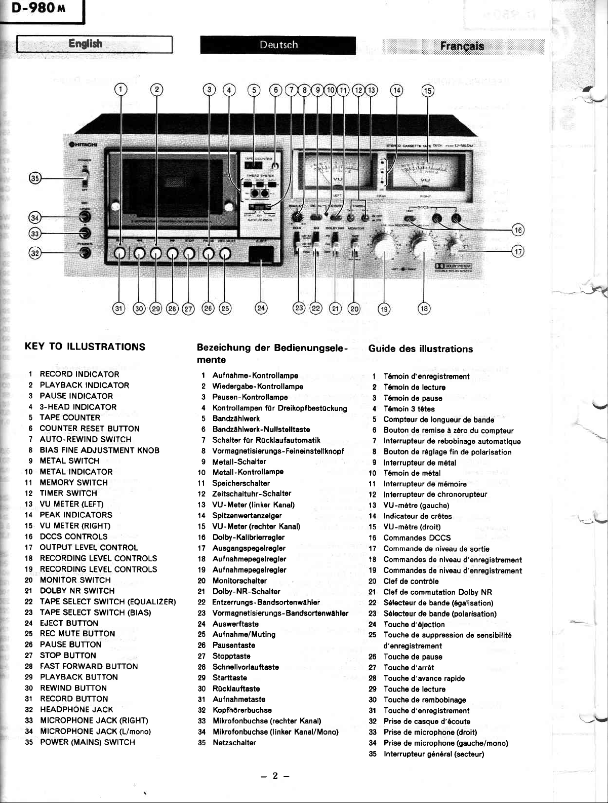
KEY
TO ILLUSTRATIONS
Bezeichung
der Bedienungsele-
Guide
illustrations
des
mente
I
RECORD
2
PLAYBACK
3
PAUSE
4
3-HEAD INDICATOR
TAPE
5
6
COUNTER
7
AUTO-REWIND
8
i
t'
BIAS FINE
I
METAL
't0
METAL INDICATOR
11
MEMORY
TIMER
12
t3
VU METER
't4
PEAK INDICATORS
15
VU METER
't6
DCCS CONTROLS
17
OUTPUT LEVEL
f8
RECORDING
19
RECORDING
20
MONITOR
21
DOLBY NR
22
TAPE SELECT
23
TAPE
24
EJECT BUTTON
25
REC
26
PAUSE
27
STOP BUTTON
FAST
28
29
PI.AYBACK
30
REWIND BUTTON
31
RECORD BUTTON
HEAOPHONE
32
33
MICROPHONE
34
MICROPHONE
35
POWER
INDICATOR
INDICATOR
INDICATOR
COUNTER
RESET BUTTON
SWITCH
ADJUSTMENT
SWITCH
SWITCH
SWITCH
(LEFT)
(RIGHT)
CONÌROL
LEVEL
LEVEL CONTROLS
SWITCH
SWITCH
SWITCH
SELECT SWTTCH
MUIE BUTTON
BUTTON
FORWARD
(MAINS)
BUTTON
BUTTON
JACK
JACK
JACK
SWITCH
KNOB
CONTROLS
(EQUALIZER)
(BtAS)
(RIGHT)
(L/mono)
I Aufnahme-Kontrollampe
2 Wiedergabe-Kontrollampe
Pausen-Kontrollampe
3
4 Kontrollampen
f0r DreihopfbestOckung
5 Bandzahlwerk
6 Bandzahlwerk-Nullstelltaste
7 Schalter f0r R0cklaufautomatil
8 Vormagnetisierungs-Feineinstellknopf
9
Metall-Schalter
10 Metall-KontrollamPe
ll Speicherschalter
l2
Zeitschaltuhr-Schalter
13 VU-Meter
(linker
Kanal)
14 SpitzenweÉanzeiger
15 VU-Meter
(rechter
Kanal)
16 Dolby-Kalibrierregler
17 Ausgangspegelregler
'18
Aufnahmepegelregler
l9 Aufnahmepegelregler
20 Monitorschalter
21 Dolby-NR-Schalter
22 Entzerrungs-Bandsortenwahler
23 Vormagnetisierungs-Bandsortenwahler
24 Auswerftaste
25 Aufnahme/Muting
26 Pausentaste
27 Stopptaste
28 Schnellvorlauftaste
29 Starttaste
R0cklauftaste
30
Aufnahmetaste
31
32 Kopfhórerbuchse
33 Mikrofonbuchse
34 Mikrofonbuchse(linker Kanal/Mono)
35 Netzschalter
(rechter
Kanal)
Tómoind'enregistrement
1
2 Tómoin
3 Tómoin
4 Tómoin
5 Compteur
6 Bouton
7 lnterrupteur
8 Bouton de réglage
I
lnterrupteur de métal
lecture
de
pause
de
3 t6t6s
de longueur
remise
de
de rebobinage
a zéro du
fin de
l0 Témoin de métal
l1 lnterrupteur
12
lnterrupteur
13 VU-mètre
14 lndicateur
15 VU-mètre
16
Commandes DCCS
17 Commande
'18
Commandes de niveau
'19
Commandes
20
Clef de contróle
21 Clef
22
Sélecteur de bande
23 Sélecteur de
24 Touche d'éloction
25 Touche
d'enregistrement
26 Touche
27 Touche d'arrèt
28
Touche d'avance rapide
29 Touche
30 Touche de rembobinage
31 Touche
Prise
32
33 Prise de microphone
Prise
34
lnterrupteur
35
de mérnoire
de chronorupteur
(gauche)
do crótes
(droit)
niveau
de
de niveau
de commutation Dolby
(ógalisation)
(polarisation)
bande
de suppression
pause
de
lecture
de
d'enregistrement
de casque d'écoute
de microphone
(secteur)
général
de bande
compteur
automatique
polarisation
de
sortie
d'enregistrement
d'enregistrement
NR
de sensibilité
(droit)
(gauche/mono)
\r'
E:_.\r,
i-rV
-2-
Page 3
English
Technische Daten :
Transistors
FET,S
Diodes
LED's
frock Syrlcn :
fopc :
fopo Spccd :
Rrcording Sy:icm ond
Froqucncy :
Bior
Eroring Syrtrm :
Erqrc Rolio:
Frcqucncy
S/N
Rcrponrc:
UD-ER
UD-EX
FeCr
Metal
(Signol
(NOR)
(CO2)
lo Noiro lolio):
Dolby NR OFF :
Dolby NR ON:
Wow ond Fluilor:
lnput
Scnrilivify
ond lnprdonrc :
Mlcrophone :
Line in :
(Record/Playback)
DIN
Clutpul Lcvol
Output
Dirlortion
Cror
Fost Forwcrd or Rowind
Powr; Supply
:
Lood lmpodqncc:
Line out :
(Record/Playback)
DIN
Headphone :
:
foll:
Betweon tracks :
Between channels
:
Powor Conrumption :
Dimcnrionr
:
Woighr:
llolor :
Hmdr:
:
Timc :
:
:
8
(For
U, C, AU)
57
(For
W, BS, FS)
55
2
48(For U, C)
(For
47
12
4 track
Cassette
FS,
W, BS,
2 channel ster€o
tape
(C-30,
AU)
60, 90)
4.75cm/s
kHz
bias, 85
AC
AC erase
(at
or more
65 dB
Hz to 18 kHz
20
to 17 kHz
30 Hz
Hz to 17
30
Hz to 20
20
30
30 Hz
20 Hz to 18
30
30 Hz to 17
20
30
30
60
60
68
68
0.03%
0.1%-
0.35
80mV, 70
0.35mV,
550mV
50
50
tl70
8 ohms
1.2%
60
30
Hz to
to 18 kHz'
Hz to 17
Hz to 2l
Hz to 19
Hz to 19 kHz'
(Weighted
dB
dB'
(Weighted
dB
dB'
(wRMS)
mV, 300 ohms
or more
kohms or
kohms or
kohms or
to 2 kohms
(r
kHz oVU)
(at
dB
(at
dB
(using
sec
90
r8 kHz
4.7
AC 120V, 60
100 to 110V/115 lo
AC
to 250V,
AC 220V, 50
240V, 50 Hz
AC
42W
(H)x
435
165
kg
8.2
Uni-Torque
DC motor
I kHz)
(+3
dB)
kHz'
kHz
(+3
dB)
kHz
(+3
kHz
dB)
kHz'
kHz
(+3
kHz
dB)
A, Refeience 3%
A, Reference 3%
to
kohms or more
kohms
more
more
mor€'
kHz) or more
1
1 kHz) or more
C-60)
(U,
Hz
C)
(For
Hz
50/60
(For
Hz
(For
(W)x
256
motorX 1
X1
5
127Y12OO to 220Y1230
FS)
BS, AU)
(D)mm
R&PcombinationheadXî
1
head X
Erase
kohms
W)
THD)
THD)
Bertúckung
:
lCs
Transistoren
FET
Dioden
LED
Spursyrlcm
:
lonband :
Bondgcrchwindigkcir :
Aufnahmo:y:tom und
Vormognctiríorungrlrrquonr
UD-ER
UD-EX
FeCr
Metall
:
:
(NOR)
(CrOz)
Lii*hryrtcm
Liirchtliimpfung
Frcquenzgong :
Frcmdsponnungrqbrlond :
ohne Dolby :
mit Dolby :
Glcichloufrchwonkungon
Eingongrcnpfindlichkcir
lmpodonz :
ond
Mikrofon :
Line in :
(Auf
Dl N
nahme/Wiedergabe) :
Aurgongrpcacl :
Abschlu0impcdonz
:
Line-out :
(Auf
DIN
nahme/Wiedergabe)
Kopfhórer :
Klirrgrod :
Kanalen :
-odcr
:
:
Rùckloufrcit :
Úbmprrchdómplung
Zwischen Spuren
Zwischen
Schnollvoilouf
Nclzrponnung und-lrrriucriz
Lci:lung:oufnohmo
Abmrrungcn
:
(8XHXD:
Gcwicht :
llotor :
Kopfbotùckung :
I
(Fúr
s7
U, C, AU)
(Fúr
W, BS, FS)
5s
2
(Fúr
48
U, C)
(Fùr
47
12
Vi€rt€lspurgeràt,
Cassetten
4,75 cm/sek
:
Wechselstrom -úorn
Wechselstrom- Lósc
>65
dB
20 bis 18.000 Hz
30 bis 17.000 Hz
30 bis 17.000
20 bis 20.000
bis 18.000 Hz
30
30 bis
20 bis 18.000 Hz
30 bis 17.000 Hz
30 bis
20 Hz bis 21 kHz
Hz bis l9 kHz
30
30 Hz bis 19 kHz'
(BeweÉungs-
60 dB
60 dB'
(Bewertungs-
dB
68
dB'
68
(wRMs)
:
0,03%
0,1%'
0.35mV, 300 Ohm b
80mV, 70
0,35mV, 4,7 kOhm
>550mV
>50
kOhm
>50
:
kOhm
>470
8 Ohm
(1
1,2%
>60
dB
>30
dB
:
90 sek.
120V, 60
'100
bis 115 bis
250V, 50/60
220V, 50
240V, 50 Hz
42W
165X435 X256
8,2 ks
ni-Torque- Motor)
U
Autsprech/Wiederg
Lóschkopfx 1
FS, I
W, BS,
-Tonband
(bei
1 kHz)
Hz'
Hz
'18.000
Hz'
17.000 Hz'
kOhm odc
kOhm'
bis 2 kOhm
kHz, oVU)
(bei
1 kHr)
(bei
1 kHz)
(Cassette
(Fúr
Hz
127V
(Fùr
Hz
(Fúr
Hz
(Fair
mm
Stl
(+Í
(t3
(+Í
(+l
U,
FS
BS
-
C
'
According
to DIN 45 500
Specifications and schematic
improvement without notice.
diagram
are subject
to change
for
-3-
performance
'GemaR
Ànderungen der
Leistu ngsverbesserungen
DIN 45
technischen
500
Daten und
ohne
des Schaltplans
Ankùndigung
vorbehalte
Page 4
.
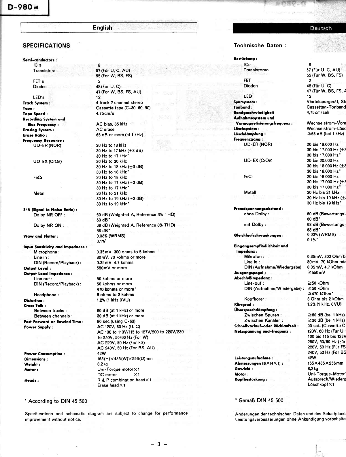
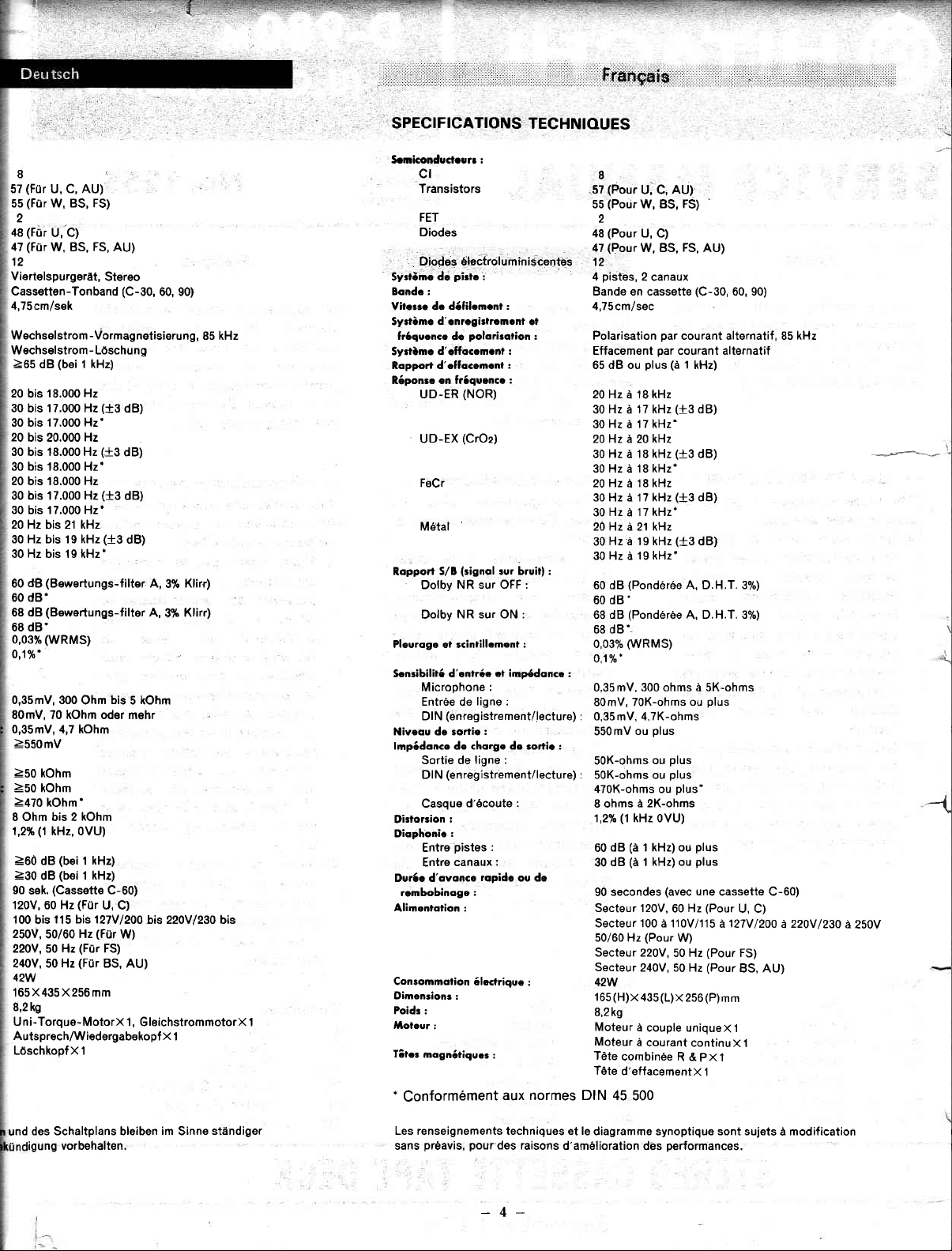
SPECIFICATIONS
TECHNIOUES
8
(Fùr
57
5s
2
48
47
12
Viertelspurgerat,
Cassetten-Tonband
4,75 cm/sek
(Fúr
(Fùi
(Fúr
C, AU)
U,
W, BS, FS)
U,-C)
FS,
W, BS,
AU)
Stéreo
(C-30,
60, 90)
Wechselstrom-Vormagnetisierung,
Wechselstrom
>65
dB
20 bis 18.000 Hz
30
bis
30 bis 17.000 Hz'
20
bis 20.000
30 bis 18.000 Hz
30 bis 18.000 Hz'
20 bis 18.000 Hz
30 bis 17.000
30 bis 17.000 Hz'
20 Hz bis 21 kHz
30 Hz bis r9 kHz
30 Hz bis 19 kHz'
dts
60
60 dB'
68 dB
68 dB'
0,03%
0,1%'
0,35mV, 300
80mV, 70 kOhm oder mehr
0,35mV, 4,7 kOhm
-
(bei
1 kHz)
17.000 Hz
Hz
Hz
(Bewertungs-filter
(Bewertungs-filtsr
(wRMS)
Ohm
Lòschu n
(+3
dB)
(t3
dB)
(+3
631
(+3
dB)
bis
g
A,
A,
5 kOhm
3%
3%
>550mV
>50
kOhm
è50 kOhm
>470
kOhm'
8 Ohm bis 2 kOhm
(1
1,2%
kHz, oVU)
>60
(bei
dB
>30
dB
90
sek.
120V, 60 Hz
100 bis
250V,
220V, 50 Hz
240V, 50 Hz
42W
165X435 X256
8,2 kg
Uni-Torque-MotorX
Autsprech/Wiedergabekopf X
LóschkopfX 1
kHz)
1
(bei
r kHz)
(Cassette
115 bis 127Vl200bis
50/60
(Fùr
Hz
(Fiir
(Fur
C-60)
U, C)
(Fùr
W)
FS)
BS, AU)
mm
1, GleichstrommotorX I
220Vl230 bis
I
Kliff)
Klirr)
85 kHz
Srniconductourr :
ct
Transistors
FET
Diodes
Diodes électroluminiscentes
pirtc
dc
Syslòne
Bondo :
dc dófilcmcnt :
Vilorrc
Syrtòmc
fróqucncc
Syrtòmc
RoppoÉ d'cffocemcnl
Róponsc on fróquencc
UD-ER
UD-EX
FeCr
M6tat
RqppoÉ
Dolby
Dolby
Pleuroge et scinlillcment
Scnsibiliró d'cntróe
Microphone
Entrée de
DIN
Niveou de iorlie
lmpódonce de chorge de sqtic:
Sortie de
Dl N
Casque
Distorsion
Dicphonic
Entre
Entre
Dur6c d'ovonce
rcmbobinoge:
Alimentotion :
Consomnotion
Dimension:
Poids :
tolcur
:
Titc: mognótiquos
.
Conformément
:
d'
cnrcgislrcmcnl cl
polorirotion
dc
:
d'clfaccmont :
r
:
(NOR)
(CrOz)
(signql
S/B
sur Lruit):
NR sur OFF :
NR sur ON :
:
cl im;Édoncc
:
ligne :
(enregistrement/lecture)
:
ligne :
(enregistrement/lecture)
:
:
ropidc
ólxlrique
:
:
ou de
:
d'écoute
:
:
pistes
canaux
:
aux normes DIN 45
8
(P.our
(Poùr
2
(Pour
(Pour
pidtes,
U, C,
W, BS, FS)
U, C)
W, BS,
2
canaux
:57
55
48
47
12
4
Bande en cassette
tl,75cm/sec
Polarisation
Effacement
Hz
î8 kHz
à
l7 kHz
à
l7 kHz'
plus (à
65 dB ou
20 Hz
30
30 Hz à
20Hz à20kHz
30 Hz à 18 kHz
30 Hz à 18 kHz-
20 Hz à 18 kHz
30 Hz à l7 kHz
Hz
17 kHz'
30
à
20 Hz à 21 k{z
Hz è î 9 kHz
30
19 kHz'
30 Hz à
(Pondéróe
60 dB
60 dB'
(Pondérée
68 dB
68 dB'
(wRMS)
0,037"
0,1%'
:
mV, 300 ohms à SK-ohms
0,35
80mV, 70K-ohms
:
0,35 mV, 4,7K-ohms
ou
550mV
,
SOK-ohms
:
S0K-ohms ou
470K-ohms ou
à 2K-ohms
I ohms
(l
1,2%
kHz 0VU)
(à
dB
1 kHz) ou
60
(
dB
1
30
secondes
90
Secteur 120V,
Secteur 100 à 110V/115
50/60 Hz
(Pour
Secteur 220V,
Secteur
240V, 50 Hz
+2W
(H)x
16s
43s
8,2 kg
Moteur
à couple uniqueXl
Moteur
à courant
Tète
combinée R &
T6te
d'effacementX
500
aU1
FS,
AU)
(C-30,
par
courant alternatif
par
courant alternatif
1
kHz)
(+3
dB)
(+3
dB)
(+3
dB)
(+3
dB)
A, D.H.T. 370)
A, D.H.T. 3%)
ou
plus
plus
ou
plus
plus'
plus
plus
kHz) ou
(avec
une
60 Hz
W)
50 Hz
(L)x
256(P)mm
continuXl
PX
1
-
60, 90)
plus
cassette C-60)
(Pour
U, C)
à127V/2OO
(Pour
FS)
(Pour
BS, AU)
î
85 kHz
,
à220V1230
^L
i
A_
-(
à250V
des Schaltplans bleiben im Sinne
und
igung
vorbehalten.
stàndiger
Les renseignements techniques et le
préavis, pourdes
sans
raisons
d'amélioration
-4-
diagramme synoptique sont sujets
performances,
dès
modification
à
Page 5
English
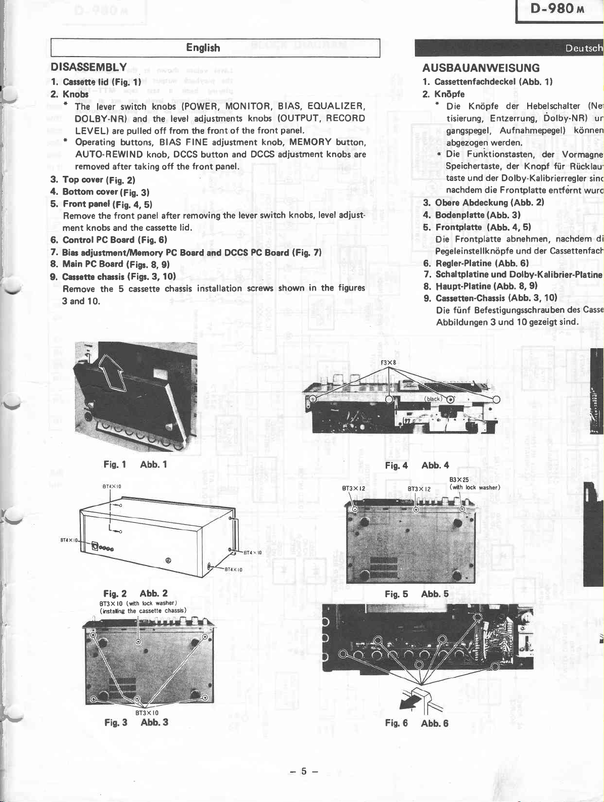
DISASSEMBLY
(Fig.
clvor
panel
the front
PC
chassir
(Fig.
1l
knobs
pulled
knob,
2)
(Fig.
3l
(Fig.
4, 5l
panel
(Fag.
Board
(Figs.
8, 9l
(Figr.3,10)
cassette chassis
(POWER,
level adjustments
from the front
off
DCCS
button
front
off the
removing the
after
6l
PC
Board and DCCS
installation
MONITOR, BIAS.
(OUTPUT,
knobs
of the front
panel.
and DCCS adiustment
panel.
lever switch
PC
Board
screws
shown
EOUALIZER,
MEMORY
level
knobs,
(Fig.
7)
in the
RECORO
button,
knobs
are
adjust-
figures
1.
Cassette tid
2. Knob
*
T
I
i
I
I
;
I
I
r
l
I
F
I
t
t
I
t
The lever switch
DOLBY-NR) and the
LEVELI are
t
Operating buttons, BIAS FINE adjustment knob,
AUTO.REWIND
removed after taking
3. Top cover
4.
Bottom
Front
5.
Remove
ment knobs and the cassette lid.
6. Control
7.
Biar
adjustmentflltlemory
8. Main PC Board
9. Cassette
Remove the 5
3 and 10.
AUSBAUANWEISUNG
1. Cassettenfachdeckel
Knópfe
2.
*
Die
Knópfe
tisierung, Entzerrung,
gangspegel,
abgezogen
*
Funktionstasten,
Die
Speichertaste, der
taste
nachdem
der
und
die Frontplatte
3. Obere Abdeckung
4.
Bodenplatte
Frontplatte
5.
Frontplatte
Die
Pegeleinstellknòpfe
(Abb.
(Abb.
6. Regler-Platine
7. Schaltplatine
8.
Haupt-Platine
Cassetten-Ghassis
9.
fùnf Befestigungsschrauben
Die
Abbildungen 3
(Abb.
der Hebelschalter
Aufnahmepegel)
werden.
Knopf fúr
Dolby-Kalibrierregler
(Abb.
3)
5l
4,
abnehmen,
und der Cassettenfach
(Abb.
6l
Dolby-Kalibrier-Platine
und
(Abb.
8,
(Abb.3,
und 10
1)
Dolby-NR) un
der Vormagne'
Rúcklaul
entférnt
2l
nachdern
9)
10)
des
gezeigt
sind.
(Net
kónnen
sinc
wurd
di
Casse
'\r
L
It
I
I
t,
I
I
t
I
I
I
I
I
-È..."
Fig.2
BT3xl0
(hstaling
Lú
Abb.2
(with
lock
the cassett€
washer)
chassÈ)
BT3X
Fis.4 Abb.
t2
Fig.5 Abb.5
BT3X;Z
4
83X25
(with
lock
washer)
F-
I
I
-5-
Page 6
1)
relschalter
Dolby-NR) und
pegel)
(Netischalter,
kónnen
I
Monitor, Vormagne-
die Pegeleinstellknópfe
von der Frontplatte einfach
der Vormagnetjsierungs-Feineinstellknopf,
pf
fùr
Rùcklaufàutomatik,
librierregler
e entfernt wurdg.
sindivon
die
Dolby-Kalibrier-
der
Rúckseite abzunehmen,
ll
n, nachdem die
:r Cassettenfach{eckel
lalibrier-Platine
10)
des
auben
reigt
sind.
Knópfe
{AUU.
i
Cassetten-Chassis entfernen, die in den
':
der Hebelschalter, die
entfernt wurden.
Zl
(Aus-
die
DEMONTAGE
1. Volet
Boutons
2.
*
Les
de
clefs
cassette
de
DOLBY-NR)
sont retirés
*
Les interrupteurs
AUTO-REWIND, DCCS et DCCS
après
dépose
Plaque
3.
supérieure
4. Plaque inférieure
5. Fagade
Déposer
boutons
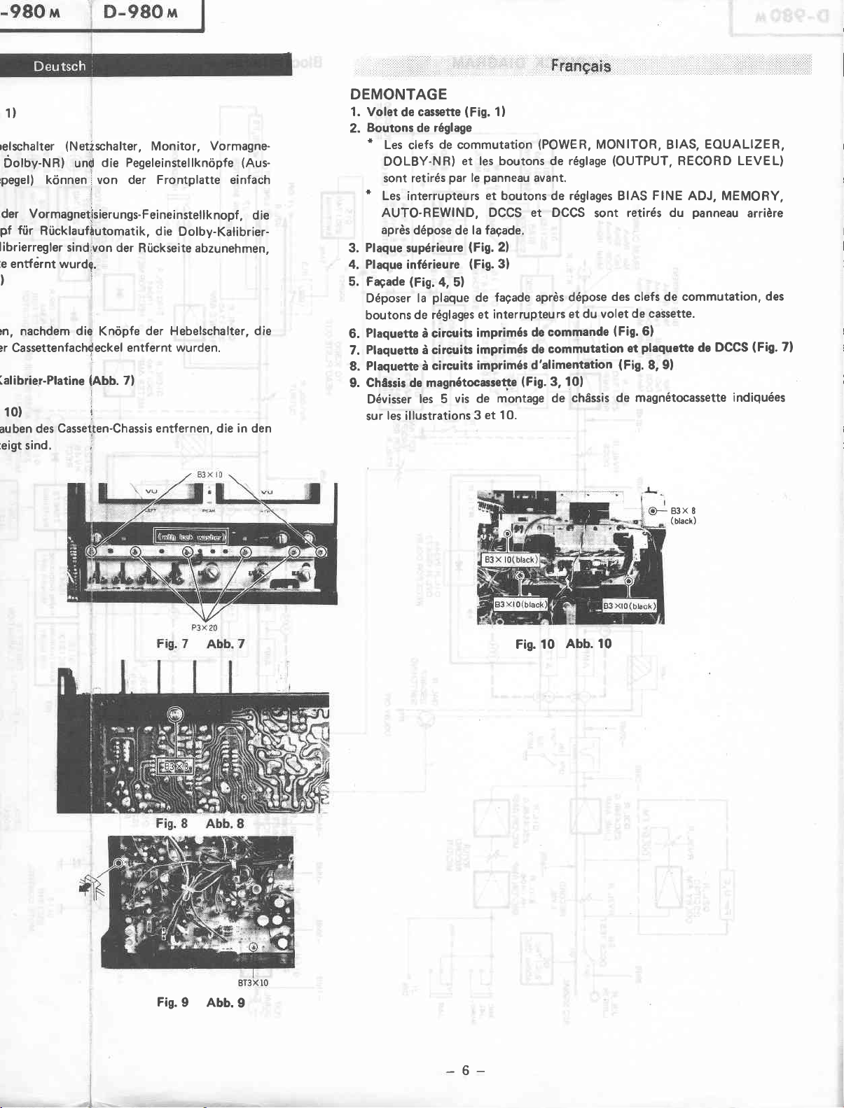
Plaquette
6.
Plaquefte à circuits
7.
Plaquette à
8.
ChAssis de magnétocassette
9.
Dévisser
sur
(Fig.4,
la
de réglages
à circtits
les 5
les illustrations
(Fig.
1!
réglage
de
commutation
et les boutons de réglase
par
panneau
le
et
boutons de réglages BIAS FINE ADJ,
la fagade.
de
(Fig.
2l
(Fig.
3)
5)
plaque
de fagade après
interrupteurs
et
imprimós
imprimés
circuits
imprimés
vis de
et 10.
3
montage de
,Frh:h.gais
(POWER,
avant.
dépose
et du volet
commande
de
commutation
de
d'alimentation
(Fig.
3, 101
ch6ssis
MONITOR, BIAS,
(OUTPUT,
sont retirés
des clefs de commutation,
de caSsette.
(Fig.
6)
ot
Plaquette
(Fis.
8,
9l
EOUALIZER,
RECORD LEVEL)
panneau
du
DCCS
de
de magnétocassette
MEMORY,
arrière
des
(Fig.
indiquées
7)
Fig. 10
Abb. 10
E}:}
(btack)
X
8
Fis.
9 Abb.9
-6-
Page 7
F
z
É
<<fÉ
É
f
s{ji
(_)
6
rsSg
@
@;o9
!*64
i
e$8e
e€€
|
.r..'.
ts
z
U
É
5<f
35à
@:.
ÉgÈ
6
î
qX
J_
lI)o
go
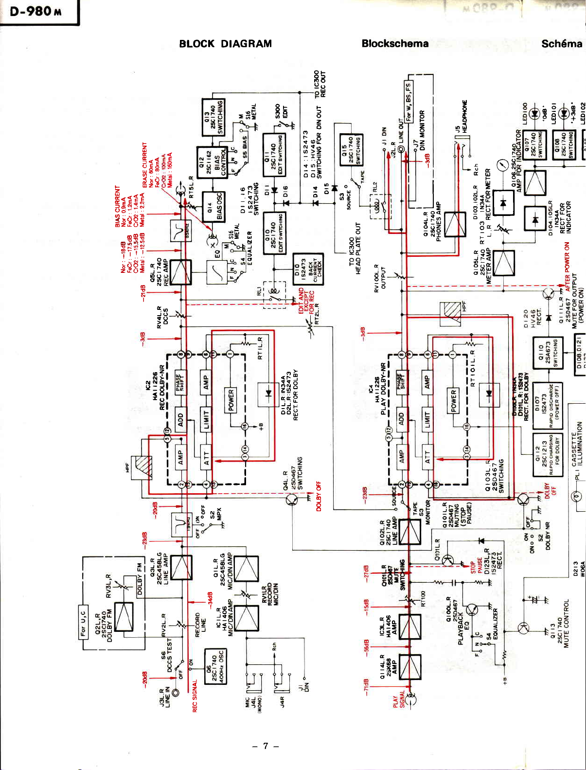
BTOCK DIAGRAM
E
g
'
-
.9
2
o
o-
E
N
G-o
JO
98
c
=H=h
oo9
-
-NF
:ot
;E
i 9r
r=
aò
È
U
t!
)
q
ilF
[,F
tt
>>
\t nF
""4
t-
-o
o
Blockschema
o
F
o
f'
t
o
0
t!
e.
NU
-I
2
r
6
/(lúl
t
Yd
&fi
to
F
l!
JG
<Ò
o
Otr
-)
ts
É.
"99
#l<
egff
gNF
E
;*
u
E
lo
rE
q
:31
o zl:
-U
oc
F
)
o
2
c)
o
o
o
oU
6È
)
o
F
f
o
oP
g<
ed
oo
F<
d
u
J]
I
oc
OF
-l
>o
e
at
o
F
o
=
E
z
ó
o
!
I
__l-
ao<
-.;Io
(
-u
e
bì6
ONI
Schéma
6
àî9
I
Fq
i
aE
5RE
óF()
=-Bg
z
o
É
I
o
È
=
I
ff
J
rl
nÍr
u!31
f3l
HI
d
J
.Rè
erÉ
oNx
ztt
-
q
--
r.t
R
))..
l:
-N
I
I
o
No-
o=
<o
o
cd
JO
a3
tt
N
@
3
1".8
J€
oi
-I
oo;
c
b
G
J
I
,lgi
-al
d1
5$g
oÍ<
9
F
Í
t.
J@
o\t
oo
-o
ON
d.-
)
o
o<
nt
oì
e
j
I
a
E
l!
N
J
)
o
U
igs
J
z
o
6
o
É
;R"
-7-
Page 8
Sch6ma
par
blocs
RgH
ò-îe
otr
gú
!1
oB
o9
-@
-<
N}
N
É *FH
-oFo
g
=-BE
+
=
y
I
c
o
c
ì
d
z
o
É
ì
I
ah
FÀ
rb
à8
àil
N5
bq
!to
+U
o
=
UF
F<
t-z
U=
6=
@J.
<-l
o=
)
d
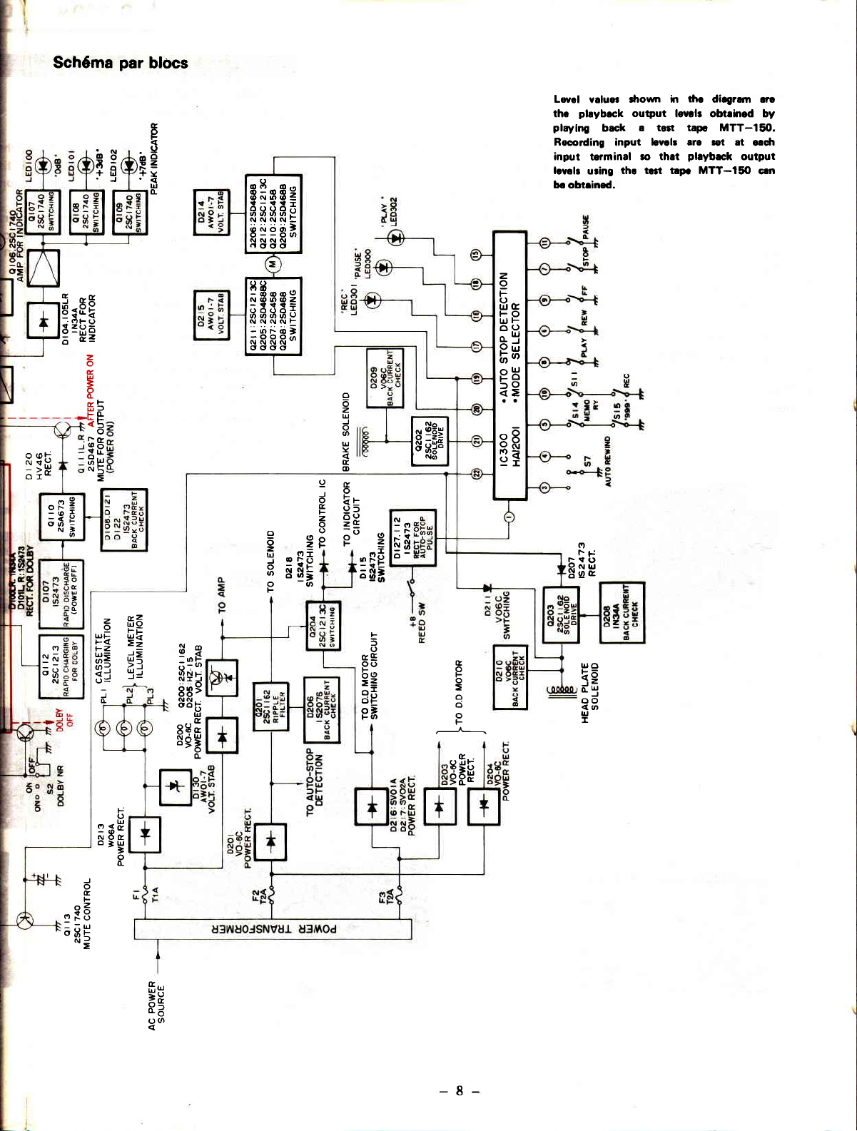
Levcl
pbybrck
c
o
F
9
o
o
z
!
+
Y
U
I
I
60 0,^
o-60:
óNO(oÉ
{-!!T
oooó;î
6664t
NNNNE
òinóó'
o--oo
NNNN
tooo
oo
9B-.o
N@O@Z
-!tfl=
oooo..f
60609
-onoì
-OOO;^
ogoo
z
o
tr
o
r!(E
FO
l!F
Òo
^uJ
Ir
9ú
thc
plqtine
Recording
inpu!
lcvelr
bc obtrined.
valuor
back
input
terminal
th! t
uring
droym ir
output
a tolt tapr MTT-150.
ro thet
tùc
diagram erc
levclr obtrhed by
levclr are rot at
phyback
lrp. MTT-tf,
rt
erdr
output
cln
i;o
9B
'rO
<=
oQ
oó
PA
YI
9a
:9
o
ò
z
U
-J
o
a
U
Y
E
o
@6P
ru
8[gÉ
E 35
6eE
()
3g
F
;frÈ
-o
PP
P(,,
z
fi6
FÈ
9
E:
d=
>-,
uÍ
q.3
6;o
oN!
NI]
s89
oo5
EEH
I
À
eE
oo
!c
sÉ
oì
l-U)
rl
FV
fL
D;
F
5
o
-o
-F
(9
z
!$
o-
BilE
fl
Ò
F
o
:E
o
ci
o
F
t!o
k0
d3
oo
<o
t!
I
^z
"F8
I:u
o3F
gHu
F
o
U
-@*
NÓC
-g
"
o
o-
J
o
È
F
=
5u
o.ó
H'
-8-
Page 9
^
,n
English
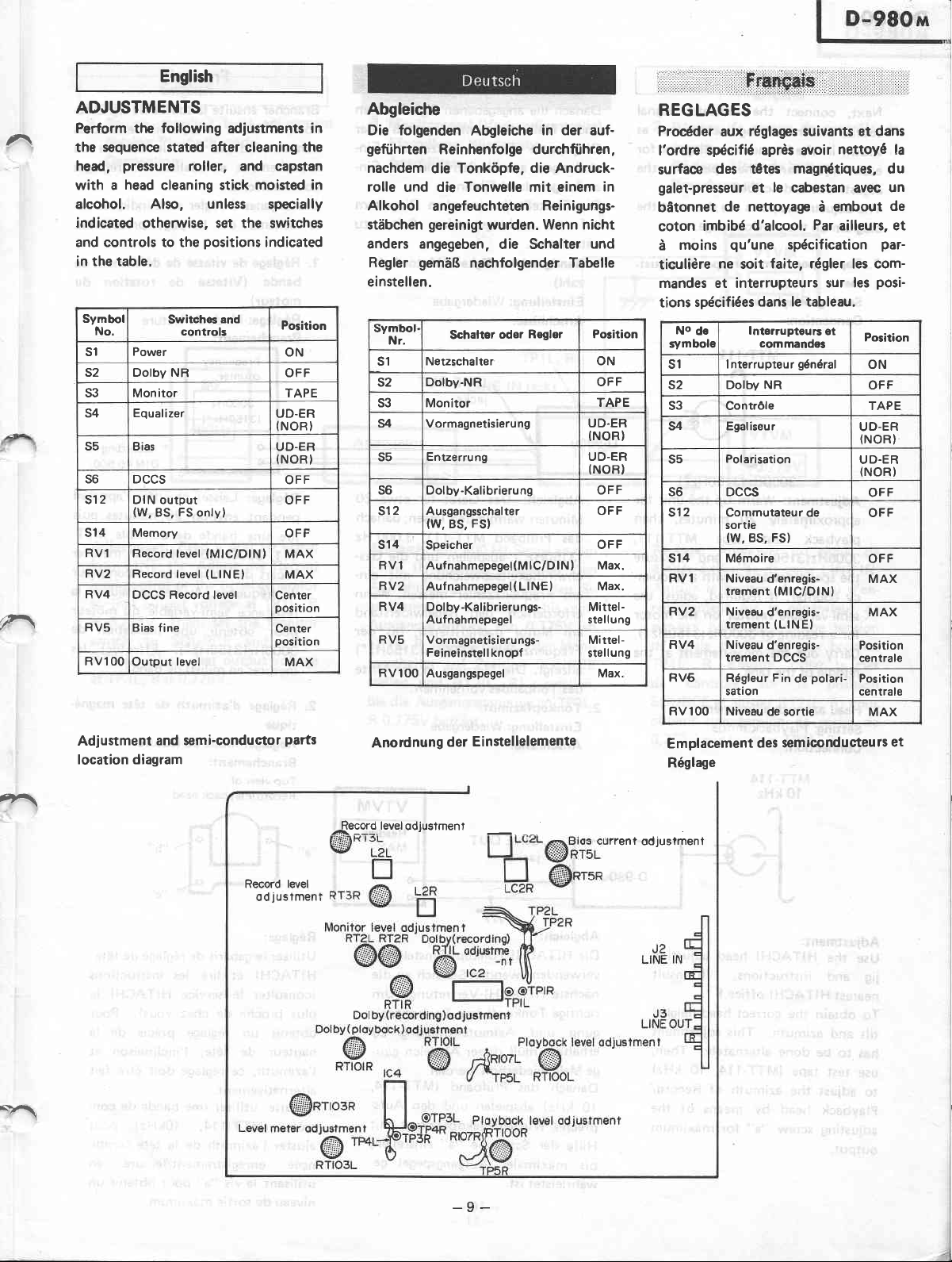
ADJUSTMENTS
Perform the following adiustments in
sequence stated after
the
pressure
head,
with a
head
roller, and capstan
cleaning stick moisted in
alcohol. Also,
indicated otherwise, set the switches
and controls to the
in the table.
Symbol
No.
s1
s2 Dolby NR
s3 Monitor TAPE
S4 Equalizer
S5 Bias
s6 DCCS
s12 DIN output
s14 Memory
RV1
RV2 Record
RV4
RV5
RV1 OO
Switch6
controls
Power
(W,
FS
BS,
onlyl
Record level
level
DCCS Record
Bias fine
level
Output
cleaning the
unless
positions
and
specially
indícated
UD-ER
(NOR}
UD-ER
(NORI
(MlC/DlNl
(LlNEl
level Center
position
Center
position
Position
ON
OFF
OFF
OFF
OFF
MAX
MAX
MAX
Abgleiche
Die folgenden
gefiihrten
nachdem
rolle
und die Tonwelle mit einem
Alkohol
stàbchen
Abgleiche
Reinhenfolge durchfiihren,
die Tonkópfe,
angefeuchteten
gereinigt
wurden.
anders angegeben,
Regler
einstellen.
gemàB
Symbol
Nr.
s1 Netzschalter ON
s2
s3 Monitor
s4 Vormagnetisieru
s5
S6 Dolby
sl2 Ausgangsschal ter
s14
RVl Auf
RV2
RV4
RV5 Vormagnetisieru
RVlOO
nachfolgender Tabelle
Schalter
Dolby-NR OFF
Entzerrung UO-ER
-Kalibrieru
(W,
FSI
BS,
Speicher
nahmepegel(M
Aufnahmepeget( LINEI Max.
-Kalibrierungs-
Dolby
Aufnahmepegel
Feineinstell knopf
Ausgangspegel Max.
in der auf-
die Andruck-
Reinigungs-
Wenn nicht
die Schalter
Regler Position
oder
ng UD.ER
ng OFF
lC/D lN, Max.
ngs-
in
und
TAPE
(NOR)
(NOR)
OFF
OFF
Mittel-
stellung
Mittel-
sîellung
.::::::::::::::.::::.::':.'::':::.:.:.:.:.È:
. i ::.
i.., i.::1i:::.::,1:,.:,..:
1!l,,,:..,
i,. i.i::..
REGLAGES
Procéder
l'ordre
surface
galet-presseur
bàtonnet
coton
moins
à
ticulière
mandes et interrupteurs
spécifiées
tions
No
d€
qymbole
s1 I nterrupteur
s2 Dolbv NR
S3 Contróle TAPE
s4 Egaliseur
s5
s6 DCCS
s12
s14
RVl
RV2
RV4 Niveau
RV6
RVlOO Niveau
réglages suivants et
aux
sÉcifié après avoir
nettoyé
des tétes magnétiques, du
et le
cabestan avsc
de nettoyage
imbibé
d'alcool.
qu'une
ne
soit
dans le tableau.
lnterrupteurs
commandes
Polarisation
Commutateur de
sortie
(w,
Bs, Fs)
Mémoire
Niveau d'enregis-
trement
Niveau
trement
trement DCCS
Régleur
sation
faite, régler les com-
(MlC/DlNl
d'enregis-
(LlNEl
d'enregis-
Fin
de sortie MAX
embout
à
Par
ailleurs, et
spécification
sur les
et
général
UD.ER
(NOR}
UD.ER
(NOR}
Position
c€ntrale
polari-
de
Position
centrale
dans
la
un
de
par-
posi-
Positaon
ON
OFF
OFF
OFF
OFF
MAX
MAX
ft\
",
Adjustment
and semi-conductor
location diagram
parts
Record level
jus
îmen
o d
t
-Record
A---.
Anordnung
level
odjusîmenî
Einstellelemente
der
urrent
Emplacement
Réglage
odjuslmenî
semiconducteu
des
rs et
-9-
Page 10
English
Next,
connect
and
source
in the
shown
zs(
I
v
I
isi
lu
,u'
I
.
each adlustment;
adiustment
The adjustment
diagram
1.
on
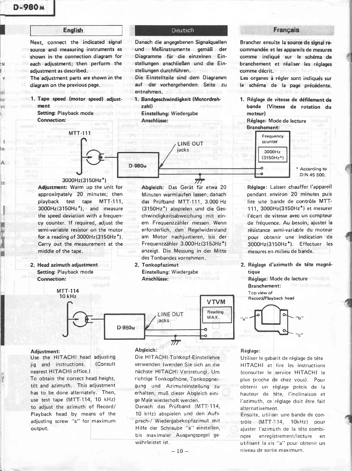
Tape speed
ment
Setting
Connection:
the indicated
meazuring
connection
then
described.
as
parts
previous
the
(motor
Playback
MTT-111
instruments
are shown
Page.
speed)
mode
il
le,
iA
te
I
i
,l
l
t
v
'a
il
-',
I
Adjustment:
approxirpately
playback
3000H2(3150H2*),
the
cy counter.
semi-variable resistor on the motor
for
Carry out the
middle of the tape.
3000H2(31
Warm up
test tape MTT-I 1 I,
speed deviation with a frequen-
lf required. adjust the
reading
a
of 3000H2(3150H2*).
2. Head azimuth
Setting:
Connection:
Playback mode
MTT.114
kHz
10
50Hz')
20 minutes; then
and measure
measurement
adiustment
signal
diagram
Perform
in the
adjust-
unit
the
at the
for
the
for
Danach die
as
und MeBinstrumente
Diagramme
stellungen
stellungen
Die Einstellteile
auf
der vorhergehenden
entnehmen.
1. Bandgeschwindigkeit
zahll
Einstellung:
Anschlússe:
Abgleich: Das Geràt
Minuten warmlaufen
das Prúfband
(3150H2*)
chwindigkeitsabweichung
Frequenzzíhler
em
erforderlich,
am Motor
Frequenzzàhler
anzeigt.
des Tonbandes vornehmen.
Tonkopfazimut
2.
Einstellung: Wiedergabe
Anschlihse:
angegebenen Signalquellen
gemàB
die
fúr
anschlieBen
durchfiihren.
einzelnen
und
sind dem
die
Diagramrn
Seite
(Motordreh-
Wiedergabe
OUT
LINE
jacks
fúr
etwa
lassen; danach
MTT- 1 1 1, 3.000 Hz
abspielen
und die Ges-
mit
messen. Wenn
Regelwiderstand
den
nachjustieren.
3.000H2
Die Messung in der Mitte
(31
bis der
50Hz
der
EinEin-
zu
20
ein-
*)
Brancher ensuite la
commandée et les appareils
comme indiqué
branchernent
comme décrit.
Les organes
schéma de
le
1. Réglage
bande
moteur)
Réglage: Mode
Branchement:
Réglage:
pendant
lire
1 1
l'écart
de
résistance
pour
de vitesse
(Vitesse
environ
une bande
1. 3000H2(3150H2*)
de vitesse
fréquence.
obtenir
3000H2(3150H2*).
mesures
2. Réglage
trque
Réglage:
Branchement:
Top
Record/Playback
en
d'azimuth
view of
source
le
sur
et réaliser les
à régler sont
page
la
de défilement
de rotation
de lecture
*
According
DtN
Laisser chauffer
minutes
20
de
contrÒle
avec
Au besoin, ajuster
semi-variable
une indication
Effectuer les
milieu de
Mode de lecture
bande.
de téte
head
de
signal re
de
mesures
schéma
indiqués
précúJente.
et
un compteur
réglages
to
45
500.
l'appareil
Puis
MTT-
mesurer
de
sur
de
du
du moteur
de
magné-
I
1
l
l
4
I
l
la
1
1
Adjustment:
Use
jig
nearest
I
To obtain
tilt and
has
use
to adjust
Playback
adjusting
output.
HITACHI
the
instructions.
and
H ITACH
the
azimuth.
to be done
tape
test
the azimuth
head
screw
head adjusting
(Consult
I
off ice.)
correct head height,
This adlustment
14, 10
Record/
of
maximum
Then,
kHz)
of
alternately.
(MTT-'l
by means
"a"
for
the
Absleich:
Die H
ITACH
verwenden
nachste
richtige
gung
erhalten,
ge
Male
Danach
kHz)
10
prech-/
Hilfe der
-Tonkopf-Einstellehre
I
(wenden
HITACHI
Tonkopf
und
Azimuteinstellung
muB
wiederholt
das Prùfband
abspielen
Wiedergabekopfazimut
Schraube
bis maximaler
wahrleistet ist.
Sie sich an die
Vertretung)
hòne,
Tonkopgnei-
dieser Abgleich
werden.
(MTT-114,
den Aufs-
und
"a"
einstellen,
Ausgangspegel
. Um
zu
eini-
mit
ge-
-10-
R égl age:
Utiliser le
HITACHI
(consulter
plus proche
gabarit
de réglage
et lire les instructions
le service HITACHI
de chez vous). Pour
obtenir un réglage
hauteur de téte,
l'azimuth,
alternat ivement.
Ensuite,
tròle
ce réglage
utiliser une bande de
(MTT
ajuster l'azimuth
nqee
utilisant
niveau
enregistrement/lecture en
la vís
de sortie maximum.
l'inclinaison
14, 1OkHz)
1
de la
pour
"a"
de
téte
précis
de la
doit étre fait
con-
pour
tète combi-
obtenir
un
le
et
1
Page 11
Engfirh
A
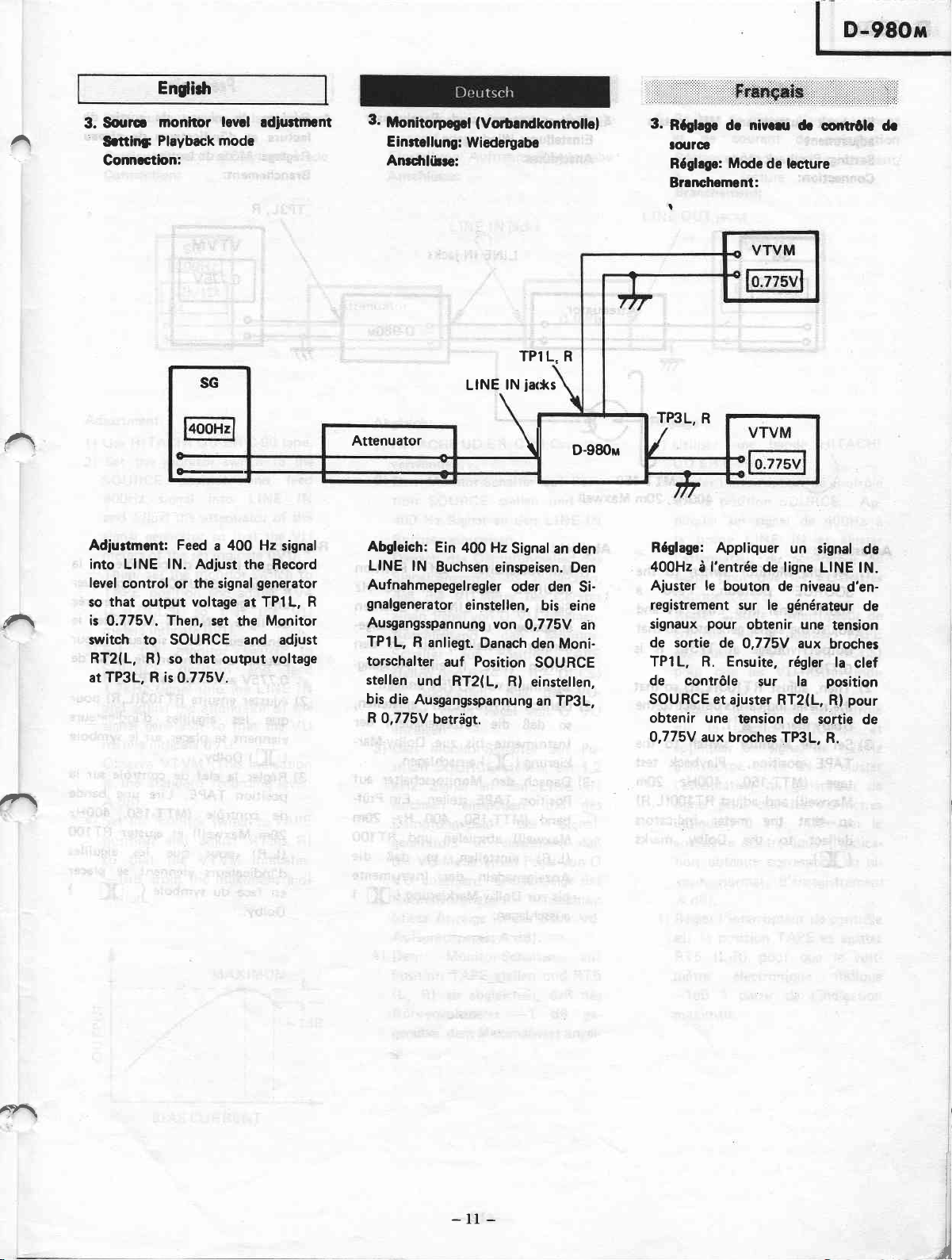
3.Souro
'
Srttinfr
Conncctbn:
moniior
Plóyback mode
lewl
rdiu*ment
3.
Monitorpegcl
E inrtellung:
Anrdrlible:
(VoÈandkontrollel
Wiederyabe
3.
Róchge
toutoe
Róghgo:
Branc-lrement:
t
dc
Mode
nivcru
de legture
dc
comr0lc dr
TPlL. R
ks
lN
LINE
Attenuator
^
Adjurtment: Feed a 400
into
LINE
level
control
that
so
is
0.775V. Then, set
switch to SOURCE and adiust
RT2(L, R)
at TP3L, R is
È-
lN.
Adjust the Record
the signal
or
output
voltage
so that ouîput
0.775V.
Hz signal
generator
at TPl L,
Monitor
the
voltage
Abgleich:
LINE
Aufnahmepegelregler
R
gnalgenerator
Ausgangsspannung
TPlL,
torschalter
stellen
bis die
R
0,775V
Ein
400
lN
Buchsen
einstellen,
R
anliegt.
auf Position
und
RT2(L,
Ausgangsspannung
betràgt.
ia<
{
Hz
Signal an den
einspeisen.
oder den
von
O,775Y an
Danach
R)
D-980u
Den
Si-
bis eine
den Moni-
SOURCE
einstellen,
an TP3L,
TP3L,
R
Róglage:
400H2 à l'entrée
Ajuster
registrement sur le
signaux
de sortie
Appliquer
le
bouton
pour
obtenir
de
O,775Y aux
de ligne
TP1L, R. Ensuite,
de contróle
SOURCE et
obtenir une
O,775V
aux broches
sur la
ajuster
tension
un signal
LINE lN.
de
niveau
générateur
une
régler
position
RT2{L,
de sortie
TP3L,
R.
de
d'en-
de
tension
broches
la
clef
pour
R)
de
,+7ìì
A".\,
-
11
-
Page 12

Englistr
Pegelmesser
VU
4. Playback
adjustment
:s
I
\
s
IU
VI
Setting
Connection:
output
Playback mode
and
motetr
4. Wiedergabepegel
Einstelluqg
Anschlibse:
Attenuator
und
Wiedergabe
lN
LINE
jacks
D-980n
Róglage de
4.
lecture
Réglage:
Branchement:
TP3L,
niveau
de
et dlindicatsurs
Mode de lecture
R
VTVM
de nireau
roÉie
ds
I
MTT.I50
and
that
R
that
so
to the
2Om
marks
Maxwell
is
Abgleich:
1l Monitorschalter
SOURCE
Signal
einspeisen
nerator
Stiften
sspannung
2l Danach
so
lnstrumente
kierung
Danach
3)
Position
band
Maxwell)
(L,R)
Anzeigenadeln
bis zur Dolby-Markierung
ausschlagen.
stellen.
den LINE
an
einstellen,
TP3L,
von
RT103(L,R)
die
daB
(ll[
den
TAPE
(MTT'150,
absPielen
einstellen,
Position
auf
400 Hz
Ein
lN Buchsen
den
und
Signalge-
bis an
Ausgang-
eine
R
0.775V
Anzeigenadeln
bis zue
ausschlagen.
)
Monitorschalter
anliegt.
DolbY-Mar-
stellen.
400
einstéllen,
Ein
Hz, 2Om
und
daB die
so
lnstrumente
der
Prùf-
RT100
(
[f
den
der
auf
]
Réglage:
1)
2)
3)
clef
Régler
position
une
de'ligne
la
SOURCE.
signal
LINE
générateur
obtenir
O,775V
Aiuster
que
viennent
(DC
Régler
position
de
20m
(L.R)
d'indicateurs
en
DolbY.
uné
aux
ensuite
les
se
ootov.
t
clef
la
TAPE.
contròle
Maxwell)
Pour
du
face
contrÒle
de
400H2 à
de
lN et ajuster
de
tension
broches
RT103(L,Rl
aiguilles
Placer
de
Lire
(MTT-150,
et aiuster
que
viennent
sYmbole
APP|iquer
l'enÎrée
signaux
de sortié
TP3L, R.
d'indicateurs
le sYmbole
rur
contrÒle
une
les aiguilles
se
(
DC
la
slr
Pour
de
Pour
sur
bande
400H2
RT100
Placer
le
la
I
Adjustment:
1)
Sct
SOU
400H2
adjust
output
0.775v.
2)
Then, adjust
the
Dolby
Set
3)
TAPE
tape
Maxwelll
so
deflect
(DC
the Monitor
RCE
meter
position.
into
signal
the signal
voltage
RTl03(L,Rl
indícators deflect
(D[
marks
the Monitor
position.
(MTT-150,
and adjust
the
that
to the Dolby
).
400H2,20m
switch
Feed a
LINE
generator
at TP3L,
).
switch
Playback test
400H2
RT100(L,R)
meter
indicators
to the
lN
so
to the
-12-
I
Page 13

English
^
^
a,
.rl
5.
Bias current, record
ment
Setting:
Connection:
Adjustment:
1) Use
2) Set
SOU
400H2
and adjust the attenuator
signal
meters
Then, set the monitor
TAPE
(L,R-DCCS)
meters indicate
3)
Set the monitor
SOU RCE
1.2kHz
and adjust
signal
meters indicate
Observe VTVM
is the
A
4)
Set the
position
so
-1dB
cation.
F
f,
o-
F
l
o
Recording/Playback
HITACHI UD-ER C-90
the
monitor switch to the
posítion
RCE
signal
generator
of the set
position
into LINE lN
so that
indicate
and
so that.the
OVU.
position
into
signal
the attenuator
generator
standard recording
dB).
monitor switch
that
from
so that
0VU.
(This
and
adjust RT5(L,R)
the VTVM
the
maximum
MAX
lewl adjust-
and
of the
the
0VU.
switch
adjust RV4
switch to
anci
the LINE
of
the VU
indication
level:
to TAPE
indicates
rM9[
mode
tape.
feed
VU
VU
feed
lN
the
indi-
-
1--
-
to
r-
1dB
5.
Vormagnetisierungsstrom,
mepegel
Einstellung:
Anschlússe:
Abgleich:
HITACHI
1)
verwenden.
2)
Monitor-Schalter
Den
tion
SOURCE
400 Hz
Buchsen
Danach
Signalgenerators
daB die
einen Pegel
AnschlieBend
Schalter
stellen
und
so
abgleichen, daB
Meter
einen
anzergen.
3) Den
Monitor-Schalter
sition
SOURCE
kHz
Signal
Buchsen
Démpfungsglied
generators
die
VU-Meter
VU
anzeigen.
nahme/Wiedergabe
Auf
jacks
lN
LINE
UD-ER
Signal an den
einspeisen.
das Dampfungsglied
C-90
stellen und ein
so abgleichen,
VU-Meter
VU
von
O
den Monitor-
Position
auf
(L,
RV4
Pegel
stellen, ein 1,2
an den LINE
einspeisen und das
des
so einstellen, daB
einen
Die Anzeige des
Ròhrenvoltmeters
(diese
Anzeige ist der Standard-
Aufsprechpegel:
4)
Den Monitor-schalter
Position
(L.
TAPE
R)
so abgleichen. daB
Róhrenvoltmerer
genúber
gt.
dem
A dBl.
stellen
-1
Maximalwert
Aufnah-
Cassette
Posi-
auf
LINE
des
des Geràtes
anzeigen.
TAPE
DCCS)
R
-
die VU-
von
Pegel
VU
O
Po-
auf
Signal-
von
beachten
auf
und
RT5
das
dB
anzei-
lN
ge-
lN
5.
Réglage
et de
Réglage:
Branch€m€nt:
LINE
Réglage:
.l
Utiliser
)
UD-ER
2)
Régler l'interrupteur
sur la
pliquer
la
l'atténuateur
signal
indiquent
Régler ensuite l'interrupteur
contròie
et ajuster
pour que
quent
Régler I'interrupteur
3)
sur la
appliquer
à
I'atténuateur
signal
indiquent
voltmètre électronique
O
tion
veau
A dB}.
4) Régler l'interrupteur
sur la
RTs
mètre électronique
-1dB
maximale.
de
niveau
courant
Mode
d'enregistrement/
lecture
OUT
iacks
une bande HITACHI
C.90.
position
SOURCE.
un signal
borne LINE
du
pour que
0
VU.
position
la
sur
RV4
les VU-mètres
vu.
0
position
un signal
la
borne
LINE
du
'pour
que
les
VU.
0
obtenue correspond
normal d'enregistrement
posltion
(L,Rl
à
TAPE
pour que
partir
de l'indication
d'enregistremant
polariration
de
de contròle
Ap-
de 400H2
lN et
générateur
les
ajuster
de
VU-mètres
de
TAPE
(L.R
DCCS)
indi-
de contròle
SOURCE et
de 1,2kHz
lN
et
ajuster
générateur
VU-mètres
Observer
de contròle
de
(l'indica-
au
ni-
le
et ajuster
le
volt-
indique
à
,t\
BIAS
CURRENT
-13-
Page 14

I
5)
the
Set
SOURCE
Reduce
generator
the signal
of
VTVM
the
from the
A.
level
Then, set
TAPE
to
VTVM
rhe
dB).
B
6)
the
Set
SOURCE
12kHz
Feed
adjust
and
signal
VTVM
standard
the
the
set
position.
Then,
indicate
lf not,
condition.
7) Confirm
tapes
CrO2
steps.
HITACHI
Use
the
Set
to CrO2
Adjust
repeat
Then,
and
signal
the
Set
8)
SOURCE
16
Feed
and
lN
the
of
VTVM
the
from
A.
level
the
Set
position
VTVM
not.
lf
condition.
English
monitor
position.
the output
(Adiust
of
the
generator
indicates
standard
monitor
the
position
(This
and observe
indication
monitor 'switch
position.
into
signal
the attenuator
generator so
indicates
monitor
ensure
811.5d8.
readiust
equalizer
Position.
RT3(L.R)
recording
that
RT5(L,R)
the
bY
UD-EX
steP
(5).
-20
switch
adjustment
the
and
bY steP
(3)
monitor
Position.
signal
kHz
adiust
signal
the
monitor
indicates
the
generator
indicate
standard
switch
ensure
and
B
readiust
11.5 dB.
RT4
switch
the signal
attenuator
so that
)
-20
recording
switch
LINE
of
that
from
dB
level
to TAPE
VTVM
the
at
following
tape.
C-90
bias switch
1 kHz
bY
mritch
LINE
into
attenuator
so
-20
recording
TAPE
to
that
at
to
dB
to
lN
the
the
A.
this
for
(2)'
to
that
dB
the
this
.,.,,,,:,i:lll:,:,'.....,,,,,,:::,'..,,,,,:lÉtf$
Posi-
5l Den Monitor-Schalter
tion
SOURCE
Ausgangspegel
tors reduzieren
glied
des
tellen), so
meter
-20
Standard-Aufsprechpegel
zeigt.
Danach
Position TAPE
is
auf
die
meters
betràgt B
6)
Den
Anzeige
Monitor-Schalter
sition SOURCE
kHz
Signal
Buchsen
Dàmpfungsgl ied des
tors
so einstellen, daB das
hrenvoltmerer
dem
Standard-Aufsprechpegel A-
anzeigt.
Schalter
stellen.
Róhrenvoltmeter
von
B
nicht.
nachjustieren.
7) Den
Abgleich fúr CrO2-Band
folgt Kontrollieren :
wie
HITACHI
verwenden
fúr
Entzerrung und Vorm-
agnetisierung
stellen. Danach RT3(L,R)
Schritt
Bend
die
1-kHz
holen.
8)Den
Monitor-Schalter auf
tion
SOURCE stellen,
kHz
Signal an den
Buchsen
Dàmpfungsglied des Signalgener-
ators
so einstellen,
Róhrenvoltmeter einen
von
-2O
Standard-Aufsprechpegel A an-
zeigt.
AnschlieRend
ter
auf
und darauf
Róhrenvoltmeter einen
von
B
nicht,
RT4 in diesem
nachjustieren.
des Signalgenera-
Signalgenerators
daB das
dB
den
des
beachten
dB).
an
einsepisen
-20
Danach
auf
Darauf achten, daB das
11,5
dB anzeigt; wenn
(L,
RTs
UD-EX C-90 Cassette
und die Wahlschalter
auf
(2)
abgleichen. Anschlie-
Schritte
Signal und
einspeisen
dB
der
Position
achten,
tl
.5
dB anzeigt,
auf
A
Anzeige
auf
ein
LINE
Den
eins-
an-
und
Po-
stellen.
(das
Dàmpfungs-
Ròhrenvolt-
gegeni.iber dem
Monitor-Schalter
stellen
Ròhrenvolt-
(diese
stellen,
den
und das
Signalgenera-
Ró-
gegenùber
dB
den Monitor-
Position
Rl
Position
einen
nochmals
(3)
mit
(51
TAPE
Pegel
CrO2
gemàB
einen
wieder-
Posi-
ein
LINE lN
und das
daB das
Pegel
gegeniiber
Monitor-Schal-
TAPE stellen
dem
daB das
Pegel
Wenn
Zustand
12
lN
16
'.'
5)
l'interrupteur
Régler
position SOURCE,
la
sur
la niveau
nuer
nérateur
ténuateur
que
le voltmètre
indique
normal d'enregistrement
niveau
A.
Ensuite,
contrÒle
et observer
tronique
respond à B dB).
6)
l'interrupteur
Régler
la
sur
appliquer
la borne
à
I'atténuateur
pour que
gnal
électronique
partir
du
strement
teur de
contróle sur
TAPE.
indique
mètre
le cas
(L,R
contraire,
en conséquence.
7l Confirmer
bandes
me
CrO2
suit.
Utiliser
Régler
C.90.
l'interrupteurs
et
UD.EX
sation
position
(L,R)
en effectuant
t2t.
Répéter
appliquant
opération
I'interrupteur de contròle
Régler
8)
position
sur la
pliquer
borne
la
I'atténuateur
pour
signal
électronique
partir
du niveau
gistrement
teur de
TAPE et voir si
tion
mètre
dB.
Bt1.5
réaluster
de signal
du
-20dB
régler l'interrupteur
sur la
(Cette
position
un
niveau normal d'enregi-
,A
Ensuite, voir si
une
CrO2.
l'opération
(5).
un signal de
contrÒle sur
électronique
RT4
i$l::.:iiìl':ii::'iii.:.:i:.:i;::.'ì,':i:..;.l,l..,i:,..i::::.:::
de contròle
sortie
de
(ajuster
générateur)
électronique
à
Partir
position
le voltmètre
indication cor-
de contròle
SOURCE
signal de
lN et ajuster
LINE
générateur
du
le
voltmètre
indique
Régler I'interrup-
.
la
Bì1,5
réjauster RT5
réglage
le
en
Procédant
bande
d'égalisation
un signal
LINE
du
que
indique
A .
Dans
HITACHI
de
Ajuster
l'oPération
de
SOURCE. Ap-
lN
générateur
le voltmètre
normal d'enre-
Régler I'interrup-
le cas contraire,
en conséquence.
dimi-
gé-
du
l'at-
Pour
du
de
TAPE
élec-
et
12 kHz
de si-
-20dB
position
le
volt-
dB. Dans
des
avec
com-
Polari-
la
sur
RT3
(3)
en
et
1 kHz
16kHz
et ajuster
de
-20dF
posi-
la
le
volt-
indique
,
à
à
à
-t4-
Page 15

D-98Otrt
^
^
A
English
NR adiustment
Dolby
6.
6.-l Record
Setting:
Connection:
Adjustment:
into LINE
TPl L, R becomes
Then, set the
to ON.
the voltage
Recording
Feed a
lN,
so that the
DOLBY NR
Adjust RTl(L,R) so
at îP2L,
-22.4dBm.
Mode
SkHz
voltage at
-30.4dBm.
Switch
R becomes
I
signal
that
6.
6.-1 Aufnahme
Attenuator
Abgleich:
LINE
daB
dBm
N R-schalter
stellen.
daB der
dBm
Dolby-NR-Abgleich
Einstellung:
Anschliisse:
lN
der
betràgt.
Aufnahme
lN
LINE
Ein 5
Buchsen
Pegel an
Danach
kHz
TP1L,
auf
(L,
RT1
Pegel an
betràgt.
R)
TP2L,
jacks
D-980u
{
J
an
Signal
einsPeisen,
R
-30'4
DolbY-
den
Position ON
einstellen,
R
-22.4
den
so
'l:il:i::::::::::::j:::1:
6.
6.-1
TP1L, R
(TP2L,
::.::::::Jl:
Réglage de Dolby NR
Enregistrement
Réglage:
BÌanchement:
Mode
R)
: .::::'.:::r::l:::,
d'enregistrement
::::::: :j
: ::
.
.::
VTVM
dBm/
-30.4
-22.4d9m
/
Réglage:
$H.
LINE
sortie
égal
so
la
sur
que
TP2L,
{
Appliquer
ru"
lN
aux broches
à
-30.4
de
clef
Ajuster
ON.
le niveau
R soit
un signal
prises
d'entrée
que
pour
dBm.
commutation
de sortie auxbroches
égal à
le niveau
TP1L. R soit
Ensuite, basculer
de Dolby
(L,
RTl
-22.4d8m.
de
Rl
de
ligne
de
Pour
t^\
Playback
6.-2
Setting
Connection:
Playback
Adiustment:
switch
5kHz
to the
signal
the voltage
-22,4dB,m.
switch
(L,
R becomes
to ON, and
R) so that the
-30.4
mode
the Monitor
Set
SOURCE and
LINE lN, so that
into
at TP3L,
Then, set the
R becomes
adjust RT101
voltage at
dBm.
feed
Dolby
TP4L,
6.-2 Wiedergabe
Einstellung: Wiedergabe
Anschlússe:
jacks
lN
LINE
Abgleich:
Position
SkHz
Buchsen
Pegel
betràlgt.
Schalter
und RT101
der
betragt.
Den Monitorschalter
SOURCE stellen
Signal
an den LINE
einspeisen,
an TP3L,
Danach den
auf Position
(1,
R) einstellen, bis
Pegel
an TP4L,R
und ein
so daR der
R
-22.4dBm
Dolby-NR-
ON stellen
-30.4d8m
auf
lN
Lecture
6.-2
de lecture
Réglage:
Branchement:
TP3L,
(TP4L,
Réglage:
sur
pliquer
prises
pour
broches
dBm. Ensuite, basculer la
commutation,de
ajuster
niveau de sortie aux borches TP4L,
R
Mode
R
R)
position,
la'
un signal de
d'entrée
que
TP3L,
RT10î
soit égal
la.clef
Régler
niveau de sortie aux
le
R soit égal à
(L,
à
-30.4
de contróle
SOURCE et
5 kHz aux
ligne
de
Dolby sur ON et
pour
R)
dBm.
LINE lN
-22.4
clef de
que
ap-
le
-15-
l
Page 16

D-980
m
CIRCUIT
BOARD
DIAGRAM
Printplattenansicht
Schéma
de
plaque
ffi
de càblage
:
Ground
Signal,
+B
:
v
POWER
PEAK INDICATOR
P.C.B.
v
\/
P.C.B.
MOTOR CONTROL
-16-
P.C.B.
Page 17

D-980m
CIRCUIT
--
r--
I
otru
I
BOARD
DIAGRAM Printplattenansicht
Schéma de
plaque
de
càblage
LUO
ÎERMINAL
LI NE IN
LINE OUT
-17
MAIN P.C.B.
-
Page 18

:
Componcnt
tide
p.tùm
I:
Ground
I
RE@RD
RECORD
{\
LINE
J
MIC,/DfN
-18-
CONTROL
J
P.C.B.
Page 19

SCHEMATIC
DTAGRAM (AMP./CONTROL
SECTTON)
S
Dr3
I
32473
BACK C
I
TMrTI
lrar"l
I'-
FGîl|lF
L"l-
r
f6s-ì
CHECK
2SCt
DCCS 4OOHZ
ol5
zSCl 7.tO
SWITCHING
o6
740
Dt5
HV-46 I
SìWITCHING
OSc
Dt4 0t
S2473 2SK6€A-N
SWITCHING HEAD AMP MIC,/DIN AMP
t4L
Q2L
2SCt740
tc tL
HAt406
2SC45€LG
LINE AMP
tc3L
EAI4OE
HEADAMP
O3L
otooL
2SD467
SWITCHING
Dlz OIL
ts2473
MIC./DIN
OtOtL
2s,D46?
SWITCHING
2SC45aLG
AME
otozL
2SC\74O
LINÈAMP
o4L tc2
25D467
SWITCHING
oro3L
2SD467
SWITCHING
tc4
HAt t226
PLAY
HA||226
REC DOLBY NR
OOLBY NR RECÎ
t-
c4 I
I
I
I
RECT FOR
DtooL
rN34A
rcR
DOLBY
DtL
tN34A
DOLBY
B IAS
2SC
I
Ot
]
(
):D!.lnt
't4dht
D30t tc300
ts2473
SWIICHING
HAt200t
II,IODE
I
I
I
L:
LEO300 LED3o|
CONTROL'PAUSE'
GL-3P
GL-3P
-REC'
LED3O2
GL-3P
'PLAY'
0300
ts2473
RECI
DI23 L
I 52474
REÒT.
oll2,Dt27
ts2473
AUTO STOP
DEI
Dl50 0il3
rS2473HC
2SCt740
0il3,Dil4
rs2076 awor-
02t4,D2
\ÓLT. STA
t_
-19-
Page 20

Stromlaufplan
DlOl
13
FoR
L
Dolay
Qro4L
2SCr74o
l_. _.. __-ls_?tz3
DoLBy REcr
oll2
29Cl?
BrAs
@NTRoL HEADPHoNEaMe
DzL
ts2473
REcr FoR
Ot2O
HV_46 esCtT+o
oot-.By
iiÈci_
Qtz
t62
?Sct
voLT:sîAB
-'l
I
I
I
1
I
I
I
I
J
OsL
REc.- Éii. lúúp.
DtO7,Ol.oe,DEt,Dt22
ts2473
ÉEói.
Schéma
Dt5t
I
s2473HC
oilO
25A673
swlrin-rnc
OiltL
2SD467
ùúÍiùò
de montage
_Qlo
*t,tfCÍî8n
Dro
*.*
..lF"tolrt."..*
qlo6
r?tr?'rtXoue
Dl r
t'tff#"1"n
Dr6
I
0t
.lfl?rl'"n rfrîféiî8"
olo7,oto8,ot09
2SCt7.lO
Dt3()
AwOt-7
PROTECTÍn
D2t5
,
)t- 7
STAB.
Q207
2SC458p
------------5WmFIN6-ERT--
r
02t
-
D zsct2t 3C 2SD468B
o20s
0208
2SD468B
LED I
sLP-248
'tNPUT'
0206
.2SD4688
ffi
LED2
SLP-248 SLp-22451
"souRcE"
q209
2SD46AB
LED3 LED4
-ourpur"
02ro
Q2t2
2cC458 2SCt2t3C
-20-
SLp-248
'REc"
LEDs
st-P-22481
'PLAY"
0200
2SCil62
\rcLT.
sraB. voLt sraB
0205
HZ-ts
Dil5
JS2473
vt3,@t4
HZ-9
\0-T. SIAV.
D2t2 02||
ls2473,vo6c
swricxrrue
D2t8 0204
ts2473
2*t2t3c
\o{-f
srAB.
^_
o20
2SCt
\OLT- S
IB
I
Page 21

ol
zSCt740
swlfcH rNG
O7,O|O8,QlO9
2SCrTulO
awot-7
PROTESIOR
o2o4
29ct2t3c 2scr162
sra€.
\oLî
I
Dl30
\oLT
LEDTOO-|O2
PEA<
.F !
o2ot
---l
sTÀ8.
cL-3P
ITDICATOR
0302
rsR34
RECT VOLT.STAB.
D30r
tsR34
RECT
D2r6 D209.D2|O
a
svor
RECT. BACK CI.,RRENT
o2t7 D200,mr
svo2B vo6c
-l
RECT. RECÍ
I
.Cfl'*Z
slvtTcH[s
D2O6
Js29z€ Isa473
D2Ot D2ú
BA6K cuRRÈXr cHEcK
,l
030t
2SCil62
o303
HZ27
VOLT. STAB,
L€D3O4
GL-3PG
"IETAL'
\lc6c
CHECK
58'g*
RECT.
rN34A
J
wo6a
I
I
I
I
I
D2t
RECI
Note
1. Voltae6
m$Urod
at b.$ ol chNis with minimum
2.
No
Circuit
Schaltkrois-Nr
Tolgranca
Toleranz
Tolóranco
Waitag€
Watl
Puissnce
Sort
Bauart
Tvpe
lolerancs
Toleranz
Tolórance
llo de circuii
No indicatod
Keino B6zoichnun0
indiquó
l.lo
M : 1000 ln
indi@t€d
No
Kein€ B€zeichnung
No indiquó
:
K
110'f
M :
t20!(
indical€d
No
Bez€ichnuno
K€ino
indiquó
No
No indicated Carbon lilm
Kdm Bozeichnung Kohlolilm
No indiqw Film
RC i
RW :
RS :
RN : Fir6d
Circuit No.
Schaltlrcis-Nr
I'lo
d8 circuit
No indi@tsd
K6ine Bgzoichnuno
indiquà
No
P: PF
No indicalod
l(gire Boroichnung
indiquè
No
J:t5'!
M |
Z :
D:
C i
E
-as,
4t',gpgi"r
I
I
I
t Í-tr
tl
lli
Rroî
I
tso.
I
1 ns.r.x-J
Iri
I
I
I
I
L
t----
i
I
ti
,t
lrl
clor
I
Jofor.u
i __
I
i
-
I
Valu€
Widorsi.nd
Val€ur
Valuo
Wirorstand
Valeur
+
Sort
Bauanl
Tvpe
,t
't
c1o2
0.1/16
|
sure to mal6
3 Be
with valu€,
Bei Bestellung
mùs$n Widqstand bzw, Kapaitàt. Spannung.
und
Bauarl
Pondre sin d'effcirer G commandes ls rósistancG
conddsateurs on
type
4 wlìon rrplrcing
re 9iatgd on
charrcte.istics.
W6nn mit
sind mùs$n di6 vo.g@hrigbgngn Kondenslqgn
rendol wqdon, da dio$ unter$hi€dlich€ Tmpsatur-
charaltùistik habon,
LoBqu€ 16
ceu
ótani dqnó lou6 caraclórisliqws
3
qui
_
snl
Voltro€
Spannung
Tm3ion
your
volla0€,
tolqan@
von
angogobon
prócisnt
capaciloF mrked
paris
bozgichreto
)f
condonsteuG
prAcisós
Mr
4
PI
Sr
No indicated
Keino Bezeichnung 50WV
No indioué
qd€rs
rasistors
of
sort
and
Widrstàndofi und Kondsnetqd
wden.
yal€ur,
t€nsion, tolóran@ et
with
list since r€quirod tomporatuE
Kondgnsatorsn
portant
roÉro
lc
la isto
dans
do
d€ temÉraiure
de 6rbon
CompGilion
Kmposition
Composilion
Wiro rcund
Oraht
Botinóoen
Oride rEîal tilm
Metalloxid
rÉtalliq6
Oryde
mtal
Motalllost
Mótalliq€ liro
12016
+801.
-m9('
l0SpF
25pF
i0
Caranic
Kerami$h
Caramiqre
Elctrclitic
Eloktrolyti$h
Elrctrolytique
Mylar
Mylar
Mylat
Poly6ior
Pory6tor
Polyester
)ryro
Styro
Styro
and captritqs
Toleranz
u$
spcili€d
X ,
auszuwhsln
X
,
piòc6
dótachóes
vdw€
O(Ohm)
1516
kW
film
lilm
uF
+îOt6
st
wr-
utilisr
-2t
-
Page 22

SCHEMATTC DTAGRAM
(DTRECT
DR|VE
MOTOR
SECTTON)
Stron
l-------r
MAIN
P.C.B
ol
2S C 458D
HALL
CURRENT CONTROL
INVERSE AMP
I
I
I
I
CELL BIAS
INPUT
D3,04 [
rs2076x2 rsÍ
AMPLI
TUDE
LIMITER
DIFFERENTIAL
TEMI
FORM
PLASTIC
-t.
ct2
lszrzs
cil
o.(
JI
z2/16
c2
033/25
D4
I
L-----J
ct3
o.o22
I
I
I
I
I
I
I
I
I
L
-22-
Page 23

Stromlaufplan
Schéma
de montage
D5
t s 2473
TEMPERATURE
SLI CER
Q2 Q3
2SD468C
DRIVE AME DRIVE
B CLASS AMP
25B562C
AME
o4
250468 C
DRIVE AMP
:ff
Q5
2 S8562 C
DRIVE
AMP
t
c5
o,t5/25
DRIVE COIL
-t
I
I
I
I
-23-
Page 24

D-980
trt
CIRCUIT
BOARD
:
Ground
DIAGRAM
Printplattenansicht
:
Signal,
*B
SWITCH P.C.B.
Schéma de
:
Component side
plaque
de càblage
pattern
I
fop Vlar
l{7o8
DRIVING
COIL
/
P.C.B.
./
ldoll òoll
l.rml.or.
rith r.d
cmaatad !o tla
tl harr.) on th. PC boord
z,
.l.m.ni.
pini.
Dollrrn
D îhql
or.
,J
3-HEAD
INDICATOR
-24-
J
P.C.B.
Page 25

WIRING
DIAGRAM
Schaltschema
L:l-::t-
I
-r
I I lAewen
I
---ì
Sct
ono
I
I
t
I
I
r
;
t
tr-
.bà
Page 26

Schéma de
càblage
APolIER
"rrRANsFof,iFR
-26-!
Page 27

:
Ground
:
Component
I
side
o-geo"
pattern
ti6lm
(
Top
vi.r )
-27
tpen<
(
-
rnoqaroR-j
îop
Vl.r)
Page 28

REPLACEMENT PARTS
LIST Ersatzteilliste Liste de
pièces
de rechange
sYi80L-N0
74 02ó8{!!
c
cl57LR
CRT
A
cRl
À
RT
I
RÎ
ILR
RT
2LR
RT
'LR
RI
'LR
RT
ó
RIIOOLR
RTIO
ILR
RT
I O]LR
RV
ILR
RV
zLR
RV
3LR
RV
4LR
RV5
RVI
OOLR
O
lLR
D
2LR
D4
04
0
l0
D
ll
012
Dtt
0t4
015
0tó
0t0oLR
OI()ILR
0
0zLR
I
D
O'LR
I
0l04LR
DlO5LR
Dl07
D
106
0l
t0
0tlt
0tt?
0ltt
P-l{o
025ótE8
0219902
0219907
50071E5
500718ó
500718ó
5007185
5007lel
5007185
5007I86
500718ó
5007184
5000551
5000551
5OOO3O7
5000r0ó
5000435
5000145
5rr072l
53r0572
5r10572
5tr0t2t
5t3057?
5t10572
5tr057t
5t10572
5!!0572
5tr057l
5lr057l
5140022
5!t0572
5l!0721
51r0572
0EscRtPttoit
I fORS
CAPAC
PoLYPRoPYLENE
tANîALUitEL€CfR0LyîlClOr{Frl0V
RES I Sî0RS
PACK
CR
PACK 120 OHM 0.0033MF
CR
oHr 0.oottilF r50v
120
SEil VARIABLE
sEr{t
vARtAELE
SEr{l
vARtaBLE
SEfl
VARlABLE
cEHt
vARtABLE
SEr{l VARIABLE
SEilt VARTABLF
sErl
vARIABL€
SEltt
VARTABLÈ
20t(
EOK
t0x
oHt(8t
5K
l0t(
stLlcoN
stLlc0N
HZ9C
sILtcoil
SILICoN
ts2tTlv€
stLtcor{
stLlcoil
stLlcoil HV-{ó
slLlcoil
stLtcori
oHH(Al
oHt(A'
OHT(BI
0Ht(Bt
oHlr(Bt
vaRtABLE 20k
vARIAELE
VARIABLE
vARlaELE
vARtABIE
vARIAELE
SEN
I.CONDUCTORS
0loDE GERr,r^iilut
0tooE
I 001
Dt00E
10
0il
zEilER 0toDE
0toDE
0H
l0
Dt0DE
100|r
0t008
Dl00E
10011
0loDE
100t1
0toDE ts247tVE
DtoDE IS2{?rvE
vARtSîoR
l0K
D I oDE
0ll
l0
DtoDE GERHANTUH
DIoDE
l00ll
5t!0721 0loDE GER|ANIUt
5!t0721
5tr072l
5!!0721
5t!0571
5tr057l
5tt072r
5tr072t
5tt0572
5t!0572
6ERHAÌ{luí
DIoDE
GER[ar{tul{
DtoDE
DIOoE GERÈANlUt{
0loDE ts247lVE
0t00E stLtcoil
6ERlANtull
DtoDE
Dt00E o€Ri^tituI
0toDE
I 00H
Dt00E
l00ll
stLtcor{
slLlcoN 1s247tXC
5600pF.-5r
4s0V
a.7(
oHn
l0K
ot{t{
t0K oHtt
4.7K oHi
220K oHll
{.7K 0Hil
t0K
oHt{
t0x oHn
2.2K OHr
lilllA toltHz 5ot{H
ls247tHc
ts2+7rHc
ts24?rxc
t5247rXC
l5?47'{c
rs24?!Hc
tsza?,lrc
lilt4A torHZ 50llx
1s247lHc
1r{taA totlxz Sort
lt{54A toxHz
lN]4A toilHz
lOttHZ
lr{34^
tsze7r toot{Hz
lti!{A lOrHt SOXI
tt{!{A loilHl
ls2e7tHc
(FOR
SorH
'ot{}t
SOxH
!ooxf
50tt
(FoRU)
C)
SYllB0L-1,10
0tlr
0lt5
012 0
Dtzt
otz2
0l2lLR
0
12{
ot27
Dlr0
D
150
0t5t
0
200
D
201
D
?02
D?02
020 I
D20{
D205
D20ó
P-NO
it!057?
513057t
5t40022
Strottt
5lr0t7t
5tro57t
5!10!22
5"0'74
5!t0462
5rt057t Dt00E
5t!0572
5tr0t01
5t30t0r
ttrot01
,!t014l
53r0l0l
5t!010t
5t!0541
5rt0572
D207 5tt0572
0208
51r07?l
0209-2lt 5tr0t0t
0212
0
21!
D2t4
D
215
0
21ó
02lt
0 218
Dt00
D
t0l
0t0
I
Dt02
0r0t
0t
LE
lc I
tC
lc z.
IC
lc {
I
ct00
LED
LED 2
ILR
'LR
04
1
5tr0572 0looE
5rt0t2t
5rr0482
5!10482
5tt0rtt
5t!0374
5tr0571
5!t057S
5tr057r
5lrl241
5rtt24l
5tt098t
5!80242
,t59652
5t50?51
5!505ót
5!t0251
5t505ó1
5r50852
5tB0l0l
5r80t0l
OESCRlPllOll
otóoE
lo0ll
0toDE
VARtSToR StLtcor{
l0r
0loDE
Dt00E
0toDE
ZENER-DloDEStLtCor{
l0K
I ODE
D
0100E
DC
DtoDE
l0 0l{
DtoDE
I5K
Dt00E
I5K
0toDE
l5K
Dt00E
ó0H
0toDE
I5X
DtoDE
l5x
ZEtiER
0loDE StLtcoli ts247llrc
, 100t
Dl00E
l00t
Dl00E
Dt00E
I5l(
l00H
zEr{ER 0toDE Hz9c
DIoDE
0c
0toDE
DC
otoDE
ó0H
DIODE
DtoDE t6247tvE
DtOoE
DIoDE stLtcox
0t00E
Dt00E lsR!{
zEilEn
6L tP6t
LED
HAltTtl'
tC
HAt40ó
lC
lr^
tc
stLtcoir
ts247lVE
stLtcor{
ls 2473
!s247,
l5?47lVE
t92{7tvE
SlLlCON All0l-7
I S2a7!VE
stLlcor{
stLlcoN
stLlc0r{
slLlcoir
st
L
SlLlcoli
stLlcor{
Dl0D€ HZ-15
stLtcolr ls?47lHc
gERrANlUt{
stLtcoN
stLtcoN
SlLtc0Ì{
slLlC0N
slLlcoN
SV-028
lS2{7t
192{7t t00nHz
lsRl4
Dt00E
HZ27
tt22ó
lcor{
1il!4A
1s2r7:rHc
xv-4ó
tootrHz
tR-gS
ls2t?tHc
v0óc
v0óc
v0óc
t0-óA
v0óc
v0óc
torHz
voóc
ls247tHc
Atot-7
Al0l-7
svola
tc HAtt0ó
HA
tC
tt226
HA1200l
tC
RADTAîloI
RAolatt0t{
SLP-248
0f0D€
DIoDE sLP-248
50HH
t0oir
-28-
Page 29

o-sso il
I
o-gr
SYIIBOL-l{0
LEO
tED
LEO
LEol00
tE0l0l
02
LE0 I
O
LED'
O
LED!
LED'02
ct
C
ILR
e2
E zLR
et
0
tLR
4 5t2t2l'
0
P-l{0
5!a0t
'
5!60101 RA0laTl0N DI0DE SLP-24S
4
5t80112
'
5!802{1
5'80241
5'8024I
O
"80242
5r8o24|
I
5t80242
51200ó4 TRANSISToR 2SC4580
5t?00?4 TRANSlSloRSlLlCot{
5t2t2tt
5t20024 TRAltslsfoR
5t2r2ot TRANSTSTOR
53?002{
0 4LR 5t21t94
0 5
5LR
C
có
0
l0
0
Il
0 12
0
t3
c14
0
l5
0l 00LR
5t?t20,
5t?t294
5)2t294
5r?t?94
,t2L2it
5:t2
0ó4t
5t21294
5!206Ò3
5)2L2q4
5r2lle4
010tLR 5t2tl94
olo2LR
0l0tLR
0t04LR
c105tR
010ó-109
5t2l?q4
5!l2l1e4
5121294
5t2l2i4
5t21294
0lI0 5r205et
0tllLR
0tl2
5t2ll94
5:t20ól'
0ll! 5t?1294
0ll4 5t2t506
0200-20! 5'20ó43
0204
5t20ót,
0205 5tzL2l2
020ó
5t2t?t2
DESCRIPTI0l{ SY|,|BOL-NO
sEÉ l -c0NDUcr0Rs
LEo
LED
LED
LED
LEO
LED
LEo
LEo
SLP224S
SLP224B
Gt lPRr
sPRI
GL
GL
'PRI
SPGT
Gt
6L lPRl
GL tPGl
12
2to{
TRANSISîoR
?30r1
9t{
r
îRANSISîoR
2r 0fi
TRAXSISIoR
ÌRANSISToR
îRANSISToR
.91
îRANSISÍOR 2SC 1740S
tRAilSlSîoR 2SC
TRANSTST0R 2SC t740S
tRANSISf0R
TRANSISfoR StLlCoN
15 0l{
îRANSISfoR 2SC 17405
TRANSlstoRStLlCoN
I5oil
TRANStSfoR
îRANSISfoR 2SD4ó7cC
ÌRANSlSt0R
TRANSISI0R
IRANSISToR
fRAt{slsl0R 2sc 1740s
TRANSISIoR
TRANSISf0R
TRAr{SlSt0RStLlCoN
60M
îRANSISToR 2504ó7BC
TRANSTSToR
80t{
TRANSISfoR zSC
îRANSISTOR
ÌRANSISîoR SILtCoN ?SCll62
l5 0H
TRaNSlSloRStLlCoN 2SCt2l3C
6 ol.t
TRANSIST0R StLtCoN
.91
TRANSISIoR
9l{
o
?S04ó6C
StLlcoN
(FoR
u,c)
SILtCON 2SB5ó2C
StLICoN 2SC4580LG
?SD4ó8c
?504ó7BC
SlLlCoN
1740S
25C 17405
2SC 1740S
?504ó7BC
2SC
1740S
2SD4ó7sC
2SC 1740S
25C 1740S
StLlCoN
t740S
?SKó6A-N
StLtCoN 2504ó88 l90ilHz
2SC458DL6
0.9ltll
l90nHZ
?sc45a0Lc
t5olllz
l9oxHz 0.or,lr
2SB5ó?C r50t1Hz
2SClló2
zSCltó2
2SAó7tC
zscl2llc
25D4ó88
190iHZ
P-N0
0207
5!200ó4
0208 5t2l2l2
c209
o2l0
5t2r2l2
5t200ó4 îRANSISToR
o2lt 5r206tt
ozl? 5120ólt
0t0t
5t20ó43
THI 53{0?31
fr 5212701
A
lt
A
lr
A
Tr
A
L 2LR
L
'
Ll00 5t52125
52L2702
5212704
5212705
5120274
52ó0'ó5
Lt00LR 52602L5
LI0t 5t5ZL?5
5Q?qrf2?
5'9IO01
5ó580ót
5619402
A
A
AFI
AF2
AFI
AF4
^F5
AF6
JI
J2L
J'LR
Jó
J'
LCILR
LC2LR
Ltl
PL
RLI
RL2
as I
as
As
R
I
I
5746157
,746411 PoilER
5746442
5746541
5894224
5720179
572017r
5720t77
5720174
5720174
5720173 FUSE
5ó51141
5ó?ó082
5ó7ó082
5ó50801
5ó51141
5ló1óó4
,2602t5
5554ó01
57620a5 P0lNlÉR
5ó4II4T
5ó4IIII REED
5ó0t321
5604t22
5ó04t21
DESCRIPTIoN
IRANSISToR 2SC458D
TRANSISIoR StLlCoN
.9|J
ÌRANSISToR
.9f
TRANSISToR StLtCoN
801{
TRANSISIoR SlLtCor{ 2SCt2lrC
80H
TRANSISToR StLtCoN 25Ctló2
0H
l5
THERTI!STER
TRANSFORlrERS
Po|{ER
Po||ER
Po|,IER
Po|,ER
StLtCoN 2504ó88
2SC4580
tt2t02-2
(FOR
u)
(FoR
FS)
(FOR
AU)
(FoR
W)
2SD4ó88
2SCt2lrc
l90r{r{Z
teorlHz 0
c0tLs
CHOKE
BIAS OSCILLATOR
CHoKE
4TntcRo H
îRAP
3!HH
CHoKE 4714tCRo H
I{ I SCELLAÀIEOUS
lqc-r.}l[rÉr"à
HALL ELEI.,tENI
S0CKEI
LEo
r{lC
PolrER CoRD
PotlER
POWER
FLAÎ CAOLE
FUSE
FUS€ ?A
FUSE
FUSE
FUSE 630MA
5P
PIN
PIN JACX
tlP
5P 0tf,t socKET
00LBY
îRAP C0lL
LEVEL
REED
LEVER
LEVER
LEVER
JACK
lA
2A
500MA
sooMA
DIN
JACK
rouLD
RELAY
RELAY
ASSETi,|ELY
C0R0
CoRD
CORD
SoCKEI
socKET
FILTER
r{ErER
LAMP
Slll
lcH
SrtîCH
Sr{tTCH
(FOR
W,
(FOR
AU)
(FOR
U, C)
(FOR
BS)
(FOR
BS)
(FOR
W)
'lMH
(pOwER) (FOR
(pOwER)(FOR
(POWER)(FOR w)
FS)
FS,
BS, AU)
u,C)
sYl
0
s
s
s
s
s
s
s
s
as0
st
A
A
A
-29-
Page 30

Ft al^A
D-980
-
m
Sy'B0L
s
s I
s 4
s 5
s ó
s
s
s
ló
s00l
^
st00-!06
A
A
A
2
7
12
P.NO OESCR
-t{0
5604212
5ó04214
5ó04211
,604224
5ól4tóó PUSH STITCH
5620A52
5ór70t8 PUSH
56t427e
5ó05081
56ttt5l
7740r2t
560{tó4 PATCH C0R0
56941ó5 PAîCI{ C0R0
t662021 socKET
óÓ:,099{ CASSEITE
I
2
5559161 lrEl{oRY
l
óÓó9IIT COUNTER CAP
4
6t546t2
ó74E89'
5
ót0!05r
ó
ó748óII
7
ó794081
8
ó794141
ó7llt5l
9
77671ó1 XASHER
625959t
l0
62214'5 t.IETER
tl
0t2ll05
L2
8741420
l3
8ó71408
T4
PI
ON
I
I
H I SCELLANEOUS
(DoLBY
Sr{lTcH
LEVER
(MONTTOR]
S[tTcH
LEVER
(EQUALIZER)
St.llfclr
LEVER
(B|AS)
SttTCH
LEVER
(DCCS
(DrN
(METAL'TAPE)
s}ltlcl'r
(FUNciloN)
AoAPTER
(OUT
OUTPUT)(FOR W,BS,FS)
(VoLTAGE
(FoR
CHASSIS
SlllCH-SLID€
SN,ITCH
pusH
srtîc-t{
RoTARY
srlrcH
PUSH
ACCESSORIES
FOR
HEAD CLEAtitX6 STICK
FOR CASSETTE
TEÎAL ASSEIIBLV
CoUi|TER
CoUl{îER 8ELî
FUNCTION
SPRING
EJECT
EUSHlN6
BUSHIN6
Bust{lNG
pUSt{
FLAT
BlN0
DT
HOLOER
BODV
(FOR
U, C)
(FOR
W, FS)
(FoR
AU,BS)
(DtN
BUTT0t{
FRATE ASSETIBLY
SCREI{
2.óltilD
SCREI-rHxDX20Hll
BIND
SCREII-SHltDXSlrl
OUTPUT)
NR)
TESI)
PLAY)
SELECTOR)(FOR W)
w)
ASSE}IBLY
(FOR
X 5l}r
(8'
W, FS, BS)
sYnBoL-NO
t5
ló
17
I8
l9
20
2l
2?
2t
24
25
?6
27
26
29
t0
]l
t2
t,
t4
t5
t6
,r
'E
t9
l0
{l
{?
rt
P-No
8?37408 FLAT
8ó99410 Bl
8óe8410 BT BlNo
8699ó10
ó67I?9I
66tt792
605Oó'' PUSH
60r2?t\
oEscRlPTlotl
sCREtl
HEAD
BlN0
scREr-3HHDtloMli
BT ElND SCREII-4|iHDXt0xL
H
I SCELLANEOUS
PANEL
FRONT
PAi{EL
FRONI
BUÍTON
PUSH Buîfolt
ó050641 PUSH BUTîoN
60'220'
PUSH BUTTON
ó'OIE8! BUITON SPRING
62'7241 EJECÎ SUTÎON
6296492
KN08
FoR
AUTo
6207'64 KNOB FOR B]AS
6267t6'
ó2o9I0t
ó287341 KiroB
6267t21 KNOB
ó29ó5tt
ó0917!'
óO917(l?
óó90t51
6I4C426
ótr9427
ó040741 B0Tî0É CoVER
ó040742 B0TÎ011
ó79óT?I
aó02408 DÎ
0745425
8ó99410
770114ó
6ó99ó10 BT
7?e17tl 8T BlN0
FoR
KNoB
Krio8
FUNCTlotl
CASSEÎÎE
DOOR
SHAFT
UPPER COVER
UPPER CovER
FELT
DCCS
ASSEÉBLY-24|HD
ASSETSLY-z?nAD
ASSETlBLY-l5tlHD
KN08
OOOR ASSETBLY
PANEL
FoR
D00R PAiIEL
CoVER
LEG
FELÎ
SCREIt-!l{llDXSHil
EINDING SCREII-Il{r'lDX25ltlt
HEAD
BtND
BT
SCREI{'3llrlDx20l{tl
Bl
8lN0
SCREI-4|}IDXl0ltn
SCREII'4i{XDXlO}llt
8ilH
X
-
'lll{D
SCRE|-!ilMDxl0rl{
ASSEXBLY
ASSET'|BLY
ASSEIIBLY
(FOR
(FOR
(FUNCTION)
(rlÉTALrllEll0RYl
(DCCS
rEsT)
(IIHER)
REr.rlND
FINE
I
(REC
|
)
(PowER,
BIAS,
(OUTPUT)
(FOR
C)
U.
(FOR
(tOR
(FOR
w, FS,
U, C, FS,
w)
AU,
SCRETJ-lrltloxlorH
BLACK
(FoR
U,C}
w, FS,
vOLUI\lE)
ÉQ,
BS)
AU, BS)
(FoR
(FoR
(BLACK)
cAssErrE
METAL FIXING)
Bs,
AU)
NR'
DOLBY
MONITOR)
(BLACKt
U, c)
w' FS' AU' Bs)
T--
I
I
I
?
I
I
I
I
I
f
I
I
I
I
d L".
tlil
i
î
òliul
lt
"
raúh
i
I
l
I
L__
Wn @ine brMre
Falb antu als in dk
anB&n
Ldry rc6
efd@ une
dam
wt€ commdé, l€
Fódsz
Zy'ie$raub
Flal @nleEunk
VE
à ne my*
hlhund$aub
K@f
tuund M bDrry $rew
Halhud-gbshtr
Vis à €tè rd bàó
ffi
erclúing sbtd
tiste rdSetuhde
cmfrnde de mtériel sul 16
tyF et h drftrsh de ta
8idiry M hDng s.@
&lUud.Sbkhn€'&
ehraub mn lhm
î
ús
&
rcon
E
r
r
&t
SdrshnEhraub
UnElq€hih
'E- rins
Srcku@'nE
E
&sum'E'
H s@
mil thM
q#ffi
b sur€ b ruk
Éi&es
pùir
qú
pr
0&6
d dóoiE
[sts,
d h
tr6iipngffi bldll wtu, u4Hrryt
-30-
b,audée
q
wih
&ns
(@l
tyFad sEe
&Bd
la listè
?
T
@
fi
und GdiS
ci €sus
Page 31

EXPLODED
VIEW
Obere und
untere
Chassisansicht
-31 -
,3
//<
Page 32

Vue
éclat6e
INSII.AT5G
$€ET(FOR
W,FS,BS}AU)
I
i-----3:l
I
llote
JACK
PC.B
Components
:
in
Die
marked
Zeichnung mit einer
dieser
Les composants
remplacement spécifiés.
liffil
"s
INrrr"rl
specifiés sur le
in
this drawing are
bezeichneten
schéma à l'aide d'un
not specified as
op
replacement
Teile sind Keine vorgeschriebenen Ersatzteile.
liumiról
ne correspondent
parts,
pas
aux composants
de
Page 33

t
Í
I
rì1_
.
CONTINUED
FOR
WITH
FI.JSE
follówing
Tàe
fuse
the
*
'
CAUTION
TYPE
SAME
SYMBOL
in the equipment.
Example
LAVEL.
js
indication of the
AGAINST
PROTECT]ON
AND SAME
symbol
This
Type
This symbol
Type 24,
FUSE REPLACEMENT
AGAINST
RATING
fuse symbol
14,250V
250V
FIRE HAZARD,
IN ACCORDANCE
FUSE
label
indicates
indicates Slow
Slow
Fuse.
Fuse.
which
Operating
Operating
REPLACE ONLY
is affixed adiacent
',..
FUSIBLE
du méme
uÎilisé.
fusible
i
réaction
DE
collés à
retardée
retardée
PRECAUTIONS
A PRENDRE
POUR
REMPLACEMENT
LE
Pourassureruneprotectioncontinuecontrelesrisquesd,inendieetd,élec-
trocution,
méme
de
indications
Les
fusible
du
Exemple
remplacer
pulssance
slivantes:
installé
fusible uniquement
le
en ténant
dans l'appareil.
symbole
Ge
type 1A
Ce
type
compte
représeritent
250V.
symbole
24,250V
des
les
repésente
représente
ave.c un
rymboles
rymbofes
un
un fusible
du fusible
fusible
modèlè
de
à:'réation
à
'
J
WITH THE
type et
còté
du
du
to
l--
!
t
i
ll
I'
L
'!
-
-33-
Page 34

1
I
i
AMERICA
HITACHI
Eastern
'1200
Tel.
Mid-Western
14fi)
Tel. 3î2-593-î550
I
I
Southern
5î0
Tel.
Western
401 West
Tel. 213-537-8383
HITACHI SALES
743-G
Tel. 808-841
SALES CORPORATIOÍ{
Regional Office
Wall Street West,
201-935-8980
Regional Office
Ave., Elk Grove
Morse
Regional Office
Plaza Drive College
404-763-0360
Regional Office
Artesia Boulevard,
CORPORATION
Waiakamilo
Rd.,
-0431
Lyndhurst,
Park, Georgia
Honolulu,
OF
New Jersey 07071
Village,
lll.
Compton,
OF }IAWAII,
Hawaii96817
60007
30349
California
90220
ITC
@HrrAcHr
HITACHI
SALES
ffi00 ÍianJ cinàaàÎìsirù;y
CORP. OF CANADA
Éoinie crait",
Tel.514-697-9150
HITACHI
Hamburg
2
Tel. 850 60
HTTACHT SALES
Hitachi
Tel.01-848-8787
HITACHT
Rissneleden
Sweden
SALES
House,
SALES
Tel.08-98
HITACHI
oàieUett
Tel.032-28050
SUOMEN
Box 151,
Tel.
HITACHI
Kuldyssen
Tel.
HTTACHI SALES
5600
Tel. 064-513621
HITACHI-FRANCE
9,
Tel. 201-25-00
HITACHI SALES
A-1180/Wien,
-î
el.
SALES
1620 Gressvit
SF-15100
Lahti 44
SALES
02-999200
Lenzburg,
Boulevard
(N43222)
EUROPA GMbH
Kleine BahnstraBe
54,
71-75
(U.K.)
Station
(Service
SCANDITAVTA
Sundbyberg,
8,
52 80
I{ORWAY
HITACHI OY
Lahti
241
A/S
13, DK-2630
A.G.
Switzerland
(Radio-Tólóvision
Ney 75018,
WAREÍ{HAÍ{DETS
Kreuzgasse
439367/ 8
Ltd.
Hayes,
Road,
Gentre:
Box
A/S
P.O. Box
10, Finland
Taastrup,
Paris,
27
Ltd.
queb{g,
'
8, West
Germany
Middlesex UBg
01-848-3551)
AB
7î38, 5-172-07
N-î6O1 Fredrikstad,
46
Denmark
Electro-Mónager)
France
GMEH
Sundbberg
;
HsRlBl,
'
4DR, England
7,
Notway
S.A.
Canada^
J
)
l
À
1
\-
HITACHI
153
Keys
SALES
Road, Moorabbin, Victoria 3189
AUSTRAIIA
Tel. 95-8722
HITACHI Ltd. TOKYO
Head Office: 5-1,
Tel. Tokyo
Address:
Cable
Codes:
'HITACHY-
All C.odes Used
JAPAT{
1-chome,
(f.2r
Pty
Ltd.
Australia
Marunouchi, Chiyoda-ku,
(80
111'l
TOKYO
lines)
Printed
in
Tokyo
Japan
(H.Mr)
 Loading...