

Page 1
SERVICE
English
MANUAL
English
Deutsch
Frongois
No.
I 188
Y
v
Y/
SAFETY
The
following
observed
1.
Since
have
when
many
specia|
teristics,
Hitachi's
Especially
power
circuit block
replaced
manufacturers.
marked
diagram
diagram.
2.
Before
returning
the
customer,
nician
must
unit
to ascertain
pletely
danger
of electrical
PRECAUTION
precautions
servicing.
parts
safeĘ
always use
replacement
critical
with
those
Critical
witn
A
in
and
a repaired
the service
thoroughly
safe
to operate
should
in the
related
charac-
genuine
parts
in
should
of
parts
the schematic
circuit
unit
test the
that
it is
without
shock.
be
unit
parts.
the
not be
other
are
board
tech-
com-
Prócautions
Bei Wartungsarbeiten
folgenden
beachten:
1. Da
Gerdtes
weisen, nur Original-Hitachi-
Ersatzteile
Teile im Netzteil
durch óhnIiche
Hersteller
kritischen
plan
Schaltplantinen
to
2. Yor
reparierten Gerótes
muB
Gerót einer
unterziehen,
daB sicherer
Gefahr von e|ektrischeą
gewóhr|eistet
SicherheitsmaBnahmen zu
verschiedene Teile dieses
Sicherheitsfunktionen
verwenden. Kritische
ersetzt werden.
Teile sind
und im Diagramm
Ą
ękennzeichnet.
der
Auslieferung
der Wartungstechniker
griindlichen
um
Betrieb
ist.
sind
sollten nicht
Tei|e
im
mit
dem
Symbol
an den Kunden
Prtifung
sicherzustellen,
ohne
Sch|ógen
die
auf-
anderer
Alle
Schalt-
der
eines
das
die
prócautions
Les
6tre
observóes
róparation
Etant
1.
doit ótre faite.
donnó
cornposants de l'appareil
possddent
Iatives
d
uniquement
rechange
effectuer
se rapporte
critiques
qui
ne doivent
remp|acćes
fabricants' Les
sont
mcompagnós
dans le schćma de montaę
A
sur |e
cóbIage.
2. Avant de
rćparć
doit
pour
prćsente
ó|ectriques'
au
proceder
s'assurer
de
sócuritó
suivantes doivent
d chaque
que
des caractóristiques re.
la
#curitó, uti|iser
des
d'origine
un remplacement.
notamment
du
bloc d'alimentation
en
aucun cas €tre
par
ce|les d,altres
pióces
schóma
ancun danger de
de
retoumer l'appareil
c|ient. le
un essai complet
A
gue
qu,une
de nornbreux
pidces
Hitachi
pidces
aux
critiques
du
symbole
plaque
technicien
l'appareil ne
chocs
de
pour
Ceci
et
de
USA
Canada
General Area
Switzerland
and Scandinavia
Great
Britain
STEREO
Hinweis:
U
c.....
w....
FS....
8S....
USA
Kanada
Allgemeine
Schweiz
Skand
G
und
inavien
roBbritannien
Gebiete
CASSETTE
March. 1979
TAPE
Remarque:
DECK
Etats-Unis
Canada
pays
Tous
Suisse et
Grande-Bretagne
Scandinavie
Page 2
English
I
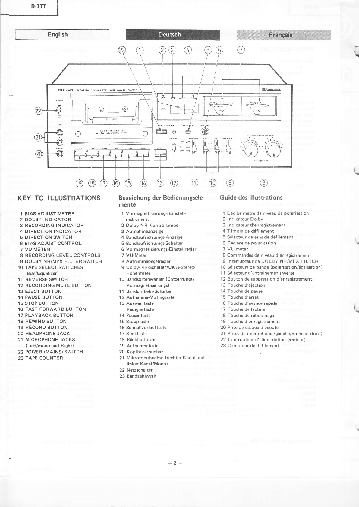
KEY TO
ADJUST METER
1 BIAS
H|fAcHl
ILLUSTRATIONS
.ilts ŁA3riYTE
2 DOLBY INDICATOR
RECORDING INDICATOR
3
DIRECTION INDICATOR
4
5 DIRECTION SWITCH
ADJUST CONTROL
BIAS
6
METER
7 VU
8 RECORDING LEVEL CONTROLS
DOLBY
9
1O TAPE SE
(
11 BEVERSE SWITCH
12 RECORDING
13 EJECT BUTTON
14 PAUSE BUTTON
15 STOP BUTTON
FAST FORWARD
16
PLAYBACK
17
18
19 RECORD BUTTON
20 HEADPHONE
MICROPHONE JACKS
21
22
TAPE COUNTER
23
NRiMPX FILTER
LECT
Bias/Equal
REWIND
(Left/mono
POWER
(MAINS}
SWITCHES
izer)
MUTE
BUTTON
BUTTON
JACK
and Right)
SWITCH
BUTTON
BUTTON
SWITCH
i^t
o..<
Bezeichung der
mente
Vormagnetisieru ngs-Ei nstell-
1
instrument
2 Dolby-N R-Kontrollampe
Aufnahmeanzeige
3
4 Bandlauf richtu
5 Bandlauf
Vormagnetisieru
6
VU-Meter
7
Aufnahmepegelregler
I
Dolby-N R-Schalter/U KW-Stereo-
9
Hóhenf iIter
Bandsortenwdhler
1 0
Vormagnetisieru
Bandumkehr-Schalter
1 1
1
Auf
2
Auswerf
13
Redigiertaste
Pausentaste
14
1 5
Stopptaste
1
6 Schnellvorlauftaste
1 7 Starttaste
Ri.icklauftaste
18
19 Auf
20 Kopfhórerbuchse
Mikrofonubuchse
2'l
linker Kanal/Mono)
Netzschalter
22
Bandzóhlwerk
23
richtungs-Schalter
nahme-Mutingtaste
taste
nahmetaste
Bedienungsele-
ngs-Anzeige
ngs-Ei nstellregler
(Entzerrungs/
ngs)
(rechter
Kanal und
Guide des illustrations
1 Dócibe|mdtre
niveau de
de
2 Indicateur Dolby
lndicateur
3
4 Tómoin
5 Só|ecteur de sens de dófiIement
Róg|age
6
7 VU mdter
Commandes
I
d'enregistrement
de dófi|ement
po|arisation
de
de niveau d'enregistrement
9 Interrupteur de DOLBY NR/MPX
10 Só|ecteurs de bande
1
1
Só|ecteur
12 Bouton de
13 Touche d,ójection
14 Touche
15 Touche d'arr6t
16 Touche
'17
Touche de lecture
18 Touche
19 Touche
Prise
20
Prises
21
Interrupteur
22
23 Compteur
d,entrairtemen
suppression d'enregistrement
pause
de
d'avance rapide
róbobinage
de
d'enregistrement
de
casque d,ócoute
microphone
de
d'alimentation
de dófilement
polarisation
(po|arisation/óga|isation)
lnverse
(gauche/mone
(secteurl
t
FILTER
et droit)
-2-
Page 3
p.777
|
English
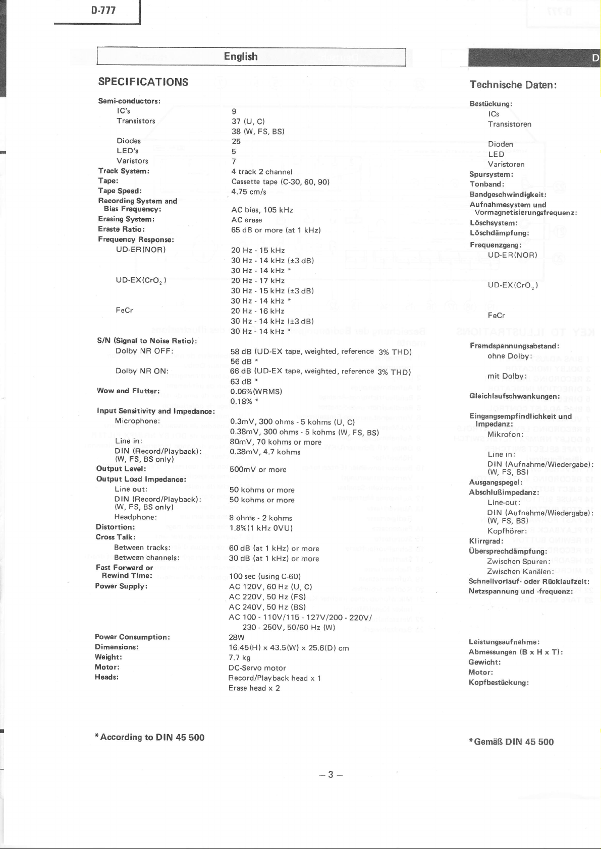
SPEC!F!CAT!ONS
Semiconductors:
lc's
Transistors
Diodes
LED'S
Varistors
Track
System:
Tape:
Tape
Speed:
Recording
Bias Frequency:
Erasing
Eraste
Frequency
S/N
Wow and Flutterl
Input
Output Level:
Output
Distortion:
Cross
Fast Forward
Rewind
Power
Powsr
Dimensions:
Weightr
Motor:
Heads:
System
and
System:
Ratio;
Response:
UD.ER(NOR)
UD-EX(CrO,
)
FeCr
(Signal
to Noise
Dolby
NR
OFF:
Dolby
NR
ON:
s€nsitivity
and lmpedance:
Microphone:
Line
in:
(Becord/Playback)
DIN
(W,
FS,
BS
only)
Load lmpedance:
Line
out:
(Record/Playback)
DIN
(W,
FS.
BS only)
Headphone:
Talk:
Between tracks:
Between channels:
or
Time:
Supply:
Consumption:
Ratiolr
:
:
9
(U,
37
C)
(W,
FS,
38
25
5
7
4
track
Cassette
BS)
2 channel
(C-30.
tape
4.75 cmls
AC bias, 105 kHz
AC erase
dB
65
or more
-
20 Hz
30
Hz
15
-
14 kHz
kHz
30Hz-14kHz*
-
20 Hz
17 kHz
-
Hz
30
1 5 kHz
30Hz-14kHz*
-'16
20 Hz
30
Hz
-
14 kHz
kHz
30Hz-14kHz*
(UD-EX
dB
58
56dB*
(UD-EX
dB
66
*
63dB
0.0670(wRMS)
*
o.'tg%
0.3mV,
300
0.38mV,
300
ohms
ohms
80mV. 70 kohms
0.38mV,4.7
500mV
50 kohms
50 kohms or
or
or more
kohms
more
more
Sohms-2kohms
1.8%(1
kHz 0VU)
'l
(at
60 dB
30 dB
100
sec
(at
(using
kHz)
I kHz)
C-60)
AC 120V.60 Hz
AC22OV,50 Hz
AC24OV,50
AC 100
23O - 25OV
28W
16.45(H)x
7.7
kg
DC-Servo
Record/Playback
Erase head
-
1 10V
motor
Hz
43.5(W)
x 2
60, 90)
(at
1 kHz)
(t3
dB)
(t3
dB)
(r3
dB)
weighted, reference
tape,
tape. weighted,
-
kohms
5
-
5
kohms
or more
or more
or more
(U,
Cl
(FSl
(BS)
-
115
127V
I
,50/60
Hz
(W)
x 25.6(D)
head
x 1
(U,
(W,
1200
cm
reference
C)
FS,
-
220V
3olo THD)
3yo THD)
BS)
I
Technische
Best0ckung:
lCs
Transistoren
Dioden
Daten:
LED
Varistoren
Spursystem:
Tonband:
Bandgeschwindigkeit:
Aufnahmgsystem
Vormagnetisierungsf requenz :
Lóschrystem:
Lóschdómpfung:
Frequenzgang:
UD-E R
UD-EX(CrO,
und
(NOR)
)
FeCr
Fremdspannungsabstand
ohne
Dolby:
mit
Dolby:
Gleichlauf
Eingangsempf
lmpedanz:
schwankungen :
indlichkeit
Mikrofon:
in:
Line
(Auf
D I
N
(w,
Ausgangspegel:
AbschIufśimpedanz:
Line-out:
D I N
(W,
nahme/Wiedergabe) :
Fs.
Bs)
(Auf
nahme/Wiedergabe)
FS,
BS)
Kopfhórer:
Klirrgrad:
Ubersprechddmpfu
Zwischen
Zwischen
Schnellvorlauf
Netzspannung
Leistungsaufnahme:
ng:
Spuren:
Kanó|en:
-
oder Riicklauf zeit :
-f
und
requenz :
Abmessungen(BxHxT):
Gewicht:
Motor:
Kopfbestiickung :
:
und
:
*According
to DIN
45
500
-3-
*GemóR
DlN 45 500
Page 4
o
(U.
C)
37
(W,
FS,
38
25
5
Viertelspurgerat,
Cassetten-Tonband
4,75
Wechselstrom-Vormagnetisieru ng, 1 05 k Hz
WechseIstrom- Lóschu ng
żos
20-15.000 Hz
30-14.000
30-14.000
20-17.000
3G15.000
3O-14.000
20-16.000
30-14.000
30-14.000
58 dB
56dB
66
63dB*
0.06%
o.'t80/o
0,3
0,38
80 mV, 70
0,38
ż5oo
ż5o
ż50
8 Ohm
1,8%
żoo
)go
100 sek.
120V,
22OV,50
240V,
10G110V/1
23G.25OV
28W
435 x 16,45 x 256 mm
7,7
Servo-G
Aufnahme/Wiedergabe x t
BS)
Stereo
(C-30,
cm/sek
(bei
aa
1 kHz)
(t3
Hz
dB)
*
Hz
Hz
(t3
Hz
dB)
*
Hz
Hz
(+3dB)
Hz
*
Hz
(UD-EX
*
(UD-EX
dB
(Mittelwert,
mV,
300 Ohm bis 5
Tonband,
Tonband, bewertet.
bewertet,
bewertet)
kOhm
mV,300 Ohm bis 5 kOhm
kOhm oder mehr
mV,4,7 kOhm
mV
kotrm
tonm
bis 2 kOhm
(l
kHz. 0 VU)
(bei
aa
1 kHz)
(bei
as
1 kHz)
(Cassette
60
50 Hz
kg
leichstrommotor
(U,
Hz
(FS)
Hz
(BS)
15-127V
,50i60
C-60)
Cl
Hz
1200-220V
(W)
60, 901
(U,
(W,
I
3% Klirr)
3% Klirr)
C)
FS, BS)
Lóschkopf x 2
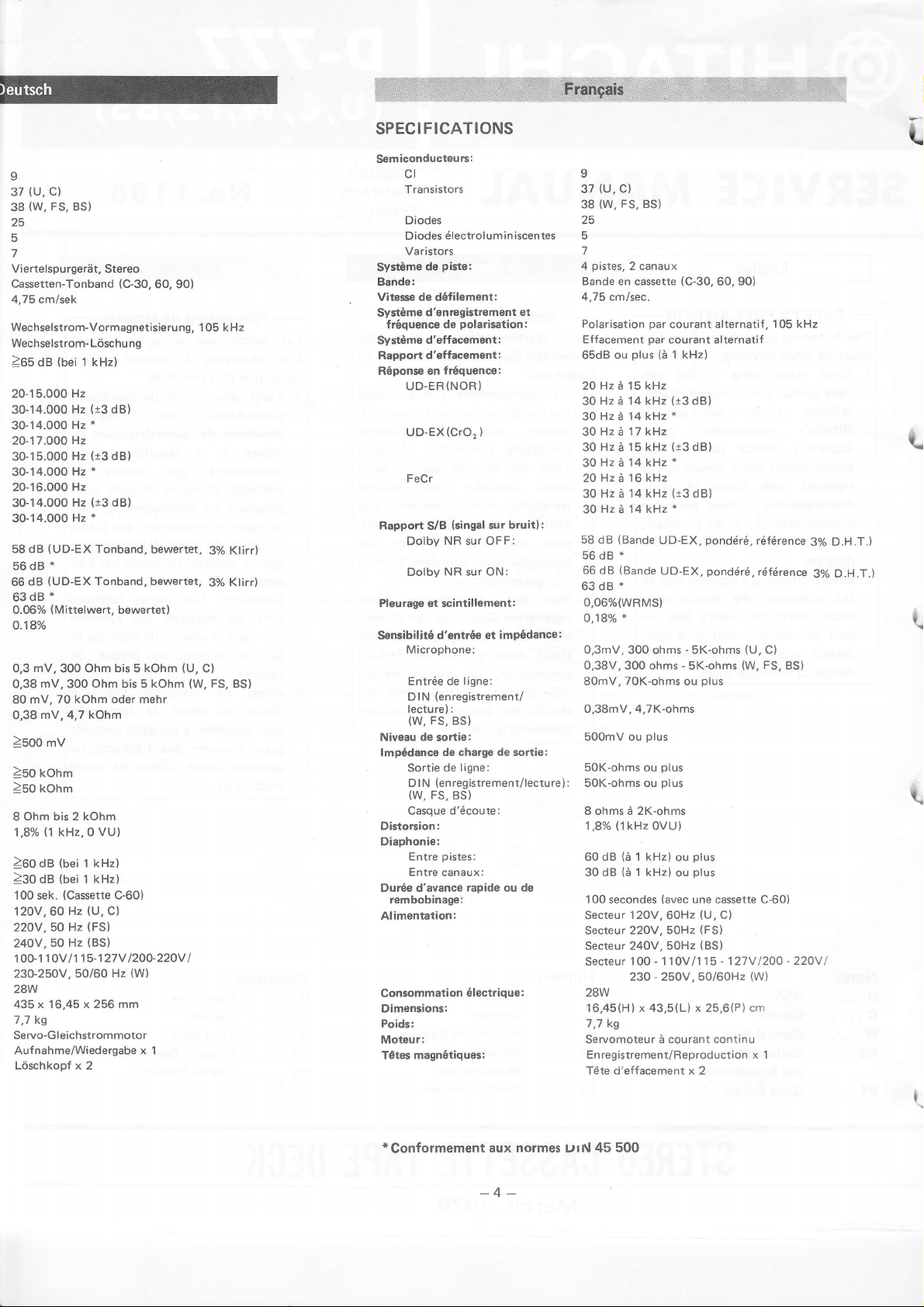
SPEC!FICATIONS
iconducteurs:
Sem
cl
Transistors
Diodes
ó|ectrolumin iscentes
Diodes
Va ristors
pistg:
SystÓme
Bande:
Vitesse de dófi|ement:
Systóme
SystCme
Rapport
Róponse en
Sensibilitó
de
d'enregistrement et
fróquence
de
d'effacement:
d'effacement:
fróquence:
UD-ER
(NOR
UD-EX(CrO,
FeCr
Rappoń
P|eurag€
S/B
NR
Dolby
NR
Dolby
et scinti||ement:
d.entróe
Microphone:
Entróe de
(enregistrement/
lN
D
lecture):
(w,
Fs,
de
Niveau
lmpódancc
sortie:
de charge de sortie:
de
Sortie
(enregistrement/lecture)
D lN
(W,
FS,
Casque
Distorsion:
Diaphonie:
Duńe
rembobinage:
Entre
Entre
d,avance
pistes:
canaux:
Alimentation:
consommation
Dimensions:
Poids:
Motour:
magnótiquos:
T6tes
po|arisation
)
)
(singa|
sur OFF:
sur
et impódance
Iigne:
Bs)
ligne:
BS}
d'ócoute:
rapide
ó|ectrique:
sur bruit):
ON:
ou de
L
9
(U,
C)
37
(W,
FS, BS)
38
25
5
pistes,
4
Bande en cassette
4,75
:
Polarisation
Effacement
65dB
20 Hz d l5 kHz
30
3OHzdl4kHz*
3oHzó17kHz
30
30Hzi14kHz*
20
30
30Hzd14kHz"
58 dB
56dB
66 dB
63dB
:
:
2 canaux
(C-30,60,90)
cm/sec.
par
courant alternati{,
par
courant alternatif
(d
plus
ou
Hz A 14 kHz
Hz
ó 15
Hz
d 16
Hz
ir
(Bande
*
{Bande
*
0,06%(wRMs)
*
o,18%
0,3mV, 300 ohms - SK-ohms
0,38V, 300 ohms
70K-ohms
80mV,
kHz
kHz
14 kHz
UD.EX,
1 kHz)
(13
dB)
(13
dB)
(i3
dB)
UD.EX,
-
SK-ohms
ou
pondóró,
pondóró,
(U,
(W.
plus
0,38mV, 4,7K-ohms
(1kHz
(a
dB
(a
secondes
120V,
240V, 50Hz
1 00
230
plus
plus
ou
plus
0VU)
1 kHz)
ou
1 kHz)
ou
(avec
6OHz
50Hz
-
1 1
0V/1
-
250V.50/60H2
x 43,5(L)
plus
plus
une
(U,
(FS)
(BS)
15
x
25,6(P)
cassette
C)
-
127V
continu
500mV ou
SoK-ohms
50K-ohms ou
8 ohms d 2K-ohms
1,8%
60
30 dB
O0
1
Secteur
Secteur 220V,
Secteur
Secteur
28W
16,45(H)
7,7 kg
Servomoteur ż courant
Enregistrement/Reproduction x 1
Tóte d,effacement x 2
105
rófórence
rófórence
C)
FS,
C-6O)
1200
(W)
cm
BS)
-
kHz
220v
3%
3%
L
D.H.T.)
D.H.T.)
I
t
I
*Conformement
aux
-4-
normes
DrN 45
500
Page 5
English
v
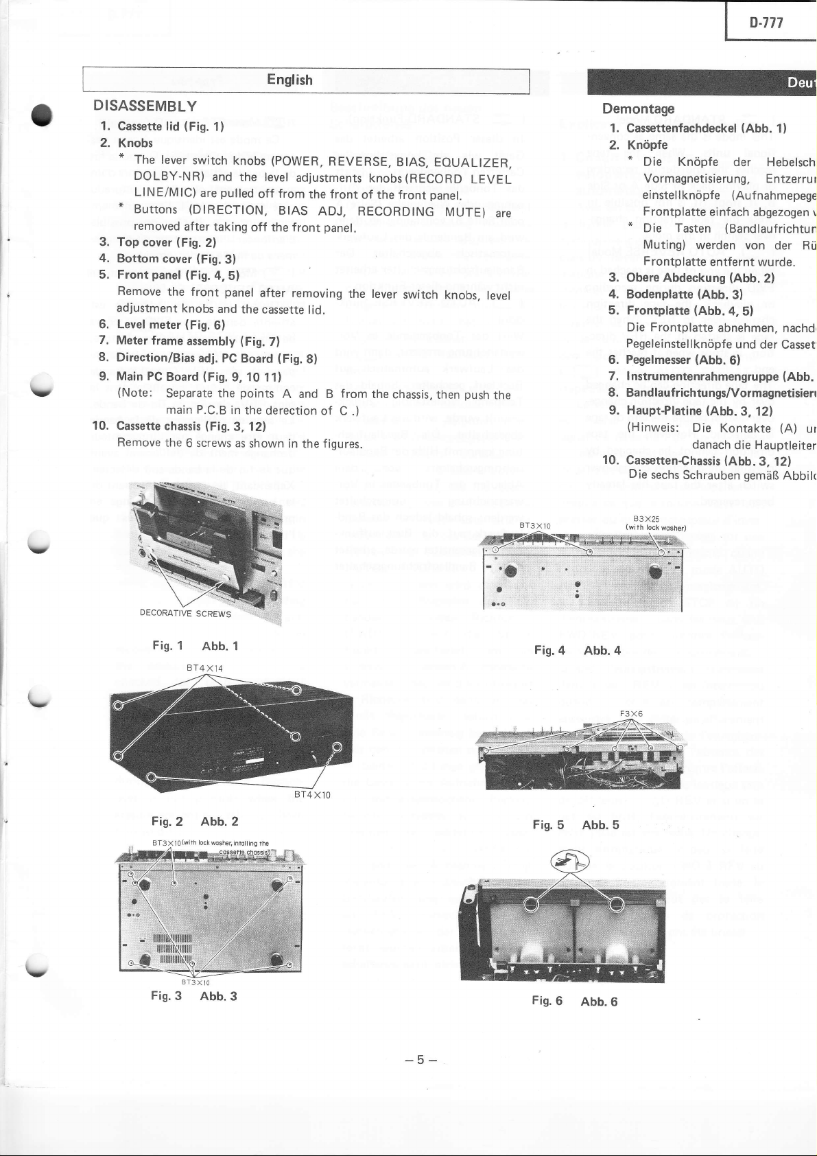
DISASSEMBLY
1.
Cassette lid
2.
Knobs
*
The
lever
DOLBY-NR)
LINEiMIC)
*
Buttons
removed
3. Top cover
4.
Bottom
5. Front
Remove
adjustment
6. Level
7.
Meter
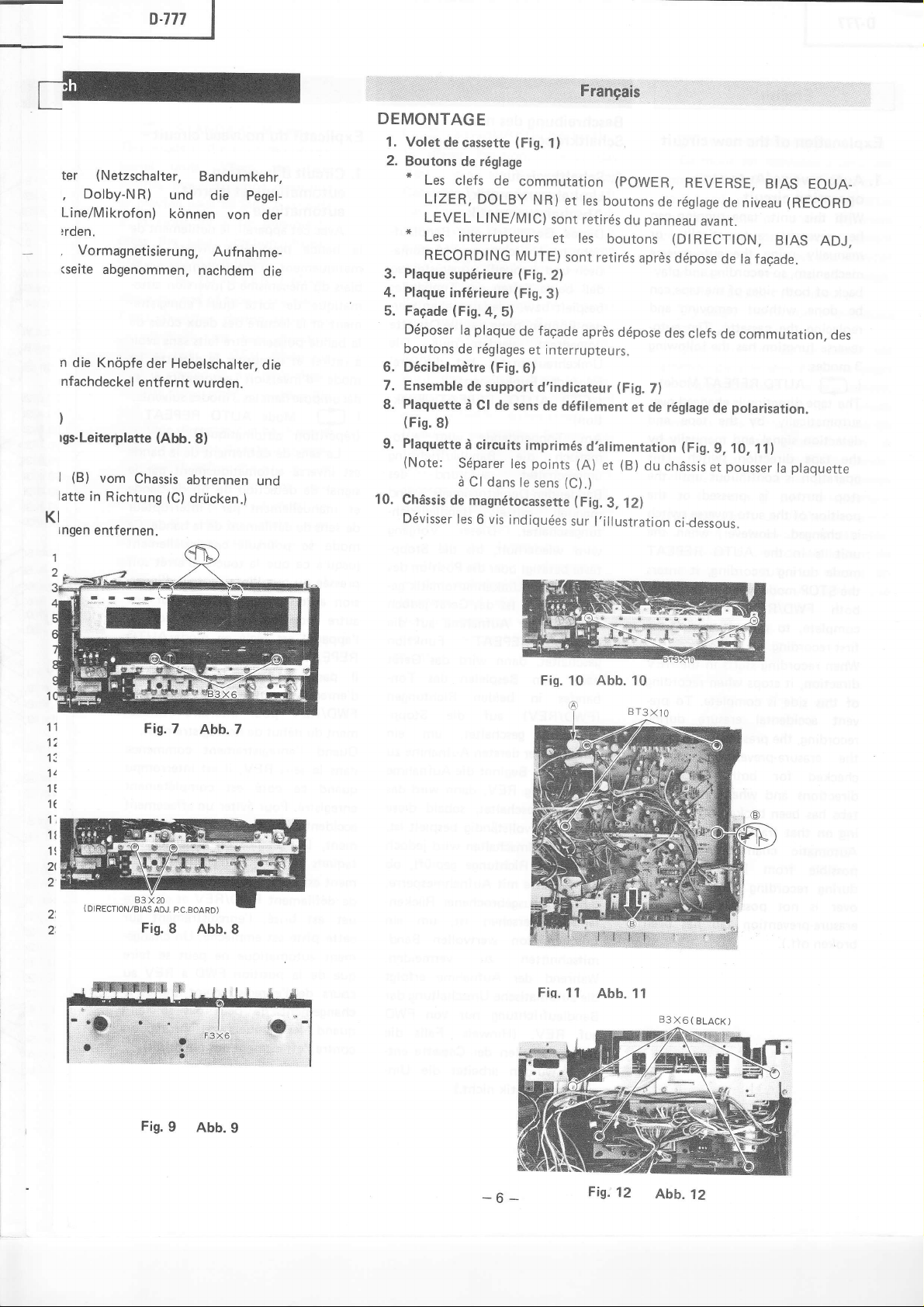
8.
Direction/Bias
Main PC
9.
(Note:
10.
Cassette chassis
Remove
(Fig.
cover
panel
the front
meter
frame
Board
Separate the
main
the
(Fig.
1)
switch
knobs
and
the tevel
pulled
are
(DtRECT|ON,
after
taking
2)
(Fig.3)
(Fig.4,5)
panel
knobs
and
the
(Fig.
6)
PC
(Fig.9,
(FiS.
Board
10 11)
assembly
adj.
points
P.C.B
in
the derection
(Fig.3,
6 screws as
12;
shown in
(POWER,
off
off
the
after
cassette
7)
REVERSE,
adjustments
from
the front
BtAS
ADJ, RECORDING
panel.
front
removing
lid.
(Fig.
8)
the
from
of
C .)
figures.
A and B
knobs
of the front
the lever
the
BIAS, EOUALIZER,
(RECORD
panel.
LEVEL
MUTE)
switch
chassis,
knobs,
then
level
push
are
the
Demontage
1. Cassettenfachdeckel
2.
Knópfe
*
Die Knópfe
Vormagnetisieru
einste||knópfe
Frontplatte
*
Die Tasten
Muting)
Frontplatte
3. Obere
4.
Bodenplatte
5. Frontplatte
Die Frontplatte
PegeIeinstelIknópfe
6. Pegelmesser
werden von
Abdeckung
(Abb.3)
{Abb.
(Abb.6)
7. lnstrumentenrahmengruppe
(Abb.
der Hebe|schi
ng, Entzerru
(Aufnahmepege
einfach
entfernt
abgezogen v
(Bandlaufrichtun
wurde.
(Abb.
2)
4,5)
abnehmen.
und
der cassetl
1)
der
nachdr
(Abb.
8. Bandlaufrichtungs/Vormagnetisierr
Hauptłlatine
9.
(Hinweis:
10.
Cassetten€hassis
Die
sechs
(Abb.3'
Die
Kontakte
danach
(Abb.
Schrauben
12)
(A)
die Hauptleiter
3'
12)
gemóB
Abbi|c
r
Rii
ur
Y
\-
Fis.
1
BT4x1Ą
Fis.2
Abb. 1
Abb. 2
BT3X]O
RąY,A
r*iti ioii
*o"r'u,l
ł
Fis.4
Fis.
5
Abb.4
Abb.5
\,
BT3X]O
Fis.3
Abb.3
-5-
Fis.6
Abb.6
Page 6
p-777
Ł
|
..i
DEMONTAGE
(Fig.
de
commutation
LlNE/M|c)
MUTE)
(Fig.
(Fig.
a' 5)
p|aque
de faęade
et
(Fig.6}
support
sens
imprimós
|es
le
6 vis
indiquóes
1)
NR)
et |es
sont
retirós
et
les
sont retirós
2)
3)
aprós
interrupteurs.
d'indicateur
de dófi|ement
d,a|imentation
points
(A)
(C).)
sens
(Fig.3'
sur |'i||ustration
(pOWER,
boutons
panneau
du
boutons
aprds
dópose
(Fig.
et de
(B)
et
du
12)
REVEBSE,
de róg|age
avant.
(DIRECTION.
dópose
des c|efs
7)
róg|age
de
(Fig.9'
ch6ssis
et
ci-dessous.
BIAS
de
niveau
BIAS
de |a
facade.
de
commutation,
po|arisation.
1o' 11)
pousser
|a
EOUA_
(REcoRD
ADJ.
des
p|aquette
(Netzschalter,
ter
Dolby-N
,
Line/Mikrofon)
)
rclen.
Vormagnetisierung,
,
(seite
abgenommen.
n
die
Knópfe
nfachdeckel
)
rys-Leiterplatte
(B)
|
vom
atte in
Richtung
KI
rngen
entfernen.
R)
und
kónnen
der
entf
ernt
(Abb.
Chassis
(C)
Bandumkehr,
die Pegel-
von
Aufnahme-
nachdem
Hebe|scha|ter.
wu rden.
8)
abtrennen
drilcken.)
der
die
die
und
1. Volet
2.
Boutons
"
*
Plaque
3.
P|aque
4.
Faęade
5.
Dóposer
boutons
Dócibelmótre
6.
7.
Ensemble
P|aquette
8.
(F.g.
Plaquette
9.
(Note:
10.
Chdssis
Dóvisser
de cassette
de róg|age
Les
clefs
L|ZER, DOLBY
LEVEL
Les interrupteurs
REcoRDlNG
supórieure
infórieure
(Fig.
Ia
de rógIages
de
d Cl de
8)
d circuits
Sóparer
d Cl dans
de magnótocassette
Ies
(
DIRECTION./BIAS
Fig.7
AOJ. PC.BOARD)
Fis.8
Fis.
9
Abb. 7
Abb.8
Abb.9
Fig.
Fiq.
10
11
Abb.
Abb.
10
11
83X6(BLACK)
-6-
Fig.12
Abb.12
Page 7
8.777
|
English
Y
Y
\-
\,
Explanation
1 . Auto-reverse/Auto-stop
of
the
new circuit
operation circuit
With this
be reversed
manually
mechanism, so recording and
back of
be done
replacing
reverse
3 modes.
(
E
The
automatically
detection signal and
the tape
operation
stop button is
position
unit. tape running can
automatically
the
using
both
sides of the tape can
auto-reverse
without removing
the
cassette.
function has the following
The
AUToREPEATMode)
direction is changed
tape
by
tape
the
manually
direction switch.
is
continuous until the
pressed
of the auto-reverse switch
is changed. However. when the
unit is in the
during
mode
the STOP mode when recording in
FWD/REV
both
comp|ete, to
first recording.
When recording
direction, it
this
of
side is complete. To
AUTO
recording, it enters
prevent
starts
stops when recording
REPEAT
directions
erasŁrg the
in
the REV
vent accidental erasure
recording, the
presence/absence
the erasure-prevention
checked for both FWD/REV
directions
tabs has been broken
ing
Automatic
possible
during recording
over
erasure-prevention tab
broken off.).
and when
on that track
changeover is
from FWD
is not
possible
one of the
off, record-
is not
(Note:
possible.
to REV
Change-
when the
has
play-
and
auto-
over
end
by
This
or the
pre-
during
tab is
only
been
Beschreibung
Schaltkreises
1.
or
is
of
des neuen
Schaltkreis
fiir
Umkehrautomatik/
Abschaltautomatik
Dieses Gerót ist
richtungs-Umschaltung
tisch und manuell)
daB beide
bespielt bzw.
den kónnen, ohne
Seiten des Tonbandes
umgedreht
Umkehrautomatik
folgenden Funktionen:
(
tion)
O
AUTO
Am Tonbandende
matisch
umgeschaltet,
Bandenden-Detektorsignals
manuell
tungsschalter.
wird wiederholt,
taste betetigt oder
Schalter
óndert wird.
wóhrend der
AUTO
gescha|tet.
nach
bandes in
(FWD/REV)
Funktion
Lóschen der
vermeiden.
Richtung
in
Gerót abgeschaItet,
eine
Vor dem Umschalten
in beiden
die Cassette mit
d.h. mit
lamelle,
Lóschen
mitschnitten zu
Wóhrend
die
Bandlaufrichtung
auf REV.
Rtickenlamellen
fernt
schaltatuomatik
die Bandlaufrichtung
mittels Bandlaufrich-
fiir
REPEAT
dann
dem
geschaltet,
Beginnt die
vo||stóndig
Seite
Richtunge
ausgebrochener Rticken-
versehen
von
der Aufnahme
automatische
wurden
mit Bandlauf-
(Automa-
ausgeri.istet,
wiedergegeben
das die
werden
muB.
hat
die drei
REPEAT FunK-
wird auto-
aufgrund des
Dieser
bis
die Stopp-
Position
die
Umkehrautomatik ge-
Ist das Gerót
Aufnahme
Funktion
wird
das Gerót
Bespielen
des Ton-
beiden Richtungen
auf die
um
dersten
REV,
(Hinweis:
Aufnahme zu
Aufnahme
dann
wird
soba|d diese
bespie|t
wird
geprtift,
Aufnahmesperre,
ist. um
wertvo||en
vermeiden.
Umschaltung der
nur von FWD
Falls
der
Cassette
arbeitet
nicht.
die
)
wer-
Cassette
Die
und
Vorgang
des
jedoch
auf die
Stopp-
ein
das
ist.
jedoch
ob
ein
Band-
erfo|gt
die
ent-
Um-
Explicatif du nouveau
1.
Circuit
d'inversion
automatique et
automatique
Avec
cet apparei|, |e
Ia bande
so
matiquement
biais
matique
ment et |a |ecture des
|a bande
retirer
i
peut
ou manuellement
du mócanisme
de sorte
puissent
et retourner la cassette.
mode d'inversion
dócompose dans
(
Cl
(rópótition
Le
Mode
sens
automatique))
de
dófi|ement de |a bande
est inversó automatiquement
de
signa|
dótection de fin
et manuellement
de
mode
jusqu,ó
pressóe
sion automatique
autre
|'apparei| est róg|ó
REPEAT
il
d'enregistrement
FWD/REV
ment du
Ouand l'enregistrement
dans
quand
enregistró.
accidentel au cours
ment, |a
taquets de
ment
de dófilement
uet
cette
ment automatique ne
que
cours
changement ne
quand
contre |,effacement
de dófi|ement
sens
poursuit
se
que
ce
que
ou
position.
en cours
passe
en mode
pour
dćbut de
le
sens
REV,
ce cótó
Pour
prósence
protection
est contró|óe dans |es deux
est brisó, |,enregistrement
piste
est
position
la
de
de l'enregistrement
les
taquets de
circuit
d'arr6t
dófi|ement de
ótre inversó
d,inversion
qua'
deux cÓtós de
faits
€tre
auto.
par
auto-
I'enregistre-
sans
avoir
Le
automatique
modes
|es 3
AUTo
suivents.
REPEAT
par
bande
de
par
l'interrupteur
de |a bande. Ce
continuellement
|a
touche d,arrćt
l,interrupteur
róg|ó
soit
Cependant,
soit
d,inver.
sur une
quand
en mode AUTo
d'enregistrement,
STOP en f in
dans les deux sens
interdire l'efface-
|,enregistrement.
commence
interrompu
il est
est
comp|ótement
óviter un
effacement
de l'enregistre-
|,absence des
ou
contre I'efface-
sens
FWD/REV
emp|echó. Un change-
peut
FWD
peut pas
ótó
ont
un
et si
sur
faire
se
a REV
(note:
faire
se
protection
brisós).
au
le
se
|e
ta
le
-7-
Page 8
English
(
This mode
tional
reaches
or
B, it
press
over
(
When
FWD
or
changes
tape is
tion,
end.
The tape direction
over by the tape direction
over switch before the
is
direction cannot be
pressing
switch
been reversed.
STANDARD
=
playing
f
playback,
is
the same
units.
the end
stops. lt
the
switch in this
the
When
back
of
is not
tape
direction
AUTo
REVERSE
end of tape
direction
the tape direction
over to REV.
started in
it stops when
during recording
Side A or Side
mode.
is reached
during
the REV direc-
it reaches
can be
detected. However.
changed by
direction
the
after
the tape has laready
change-over
Mode)
possible
end of tape
as conven-
the
tape
change-
Mode)
recording
When
the
the
changed
change-
the tape
(
In
Gerót
Cassetten.Tonbandgerót.
to
in
das Tonband
nahme
oder
wird
automatisch
Bandlauf
nicht wóhrend
(
tion)
Wird
wórtsrichtung erreicht.
das
RUcklauf
Tonband
gespult
abgeschaltet.
tung kann mit Hilfe
richtungsschalters
Ablaufen
wórtsrichtu ng
werden;
laufwerk
tion umgeschaltet
STANDARD.Funktion)
=
dieser Position
wie ein
oder
Seite B) volIstóndig
am Bandende
konventione||es
włihrend
Wiedergabe
das
abgeschaltet.
richtungsschalter
dieser Funktion.
:]
AUTO
das
REVERSE
Tonbandende
Laufwerk automatisch
geschaltet.
vollestiindig
wurde, wird
des
sobald
auf
das
D ie
Band
des
Tonbandes
umgeschaltet
jedoch
die
Ri.icklauffunk-
wurde,
arbeitet
der
(Seite
ab,
Laufwerk
arbeitet
FUNK.
in
dann
Sobald
zuriick-
Laufwerk
lauf rich-
Bandlauf-
vor
in Vor-
das
Band-
arbeitet
das
Lóuft
Auf-
dann
Der
Vor-
wird
auf
das
dem
type.
Ouand
au cours d'un
pas possible
automatique
(normat))
d celui
de change-
des
la
lecturedu
fin
UoOe
mode
du mime
bande
est
ou du
l'interrupteur
de mode
Mode
STANDARD
est identique
atteinte
ou d'une
cótó B |,entrainement
ll n'est
de
dófilement.
d'inversion
T
Ce
appareils
de la
A
enregistrement
cÓtó A
est interrompu.
d'enfoncer
ment
(
1
AUTO REVERSE)
Ouand
atteinte
de
l'enregistrement
Ie
sens
passe
commence
sens
Le
sens de dófi|ement
peut
dechange
que
Xependant,
|a
bande
pressant
I'inversion
la f
dans le
de dófiIement
en
sens
d
REV,
s'arr6te en fin
€tre
changó
ment
|a fin
de |a bande
|e
ne
l'interrupteur
ait eu lieu.
in de la
FWD
sens
ou
d'une lecture,
REV.
Quand
6tre
entrainóe
par
|'interrupteur
de dófi|ement
soit dótectóe.
sens de
peut
dófi|ement
ótre
bande
au cours
de
Ia bande
la bande
de
de |a
changó
aprds
est
dans |e
bande.
bande
avant
de
en
que
der Bandlaufrichtungsschalter
nicht.
-8-
Page 9
a
\,
\,
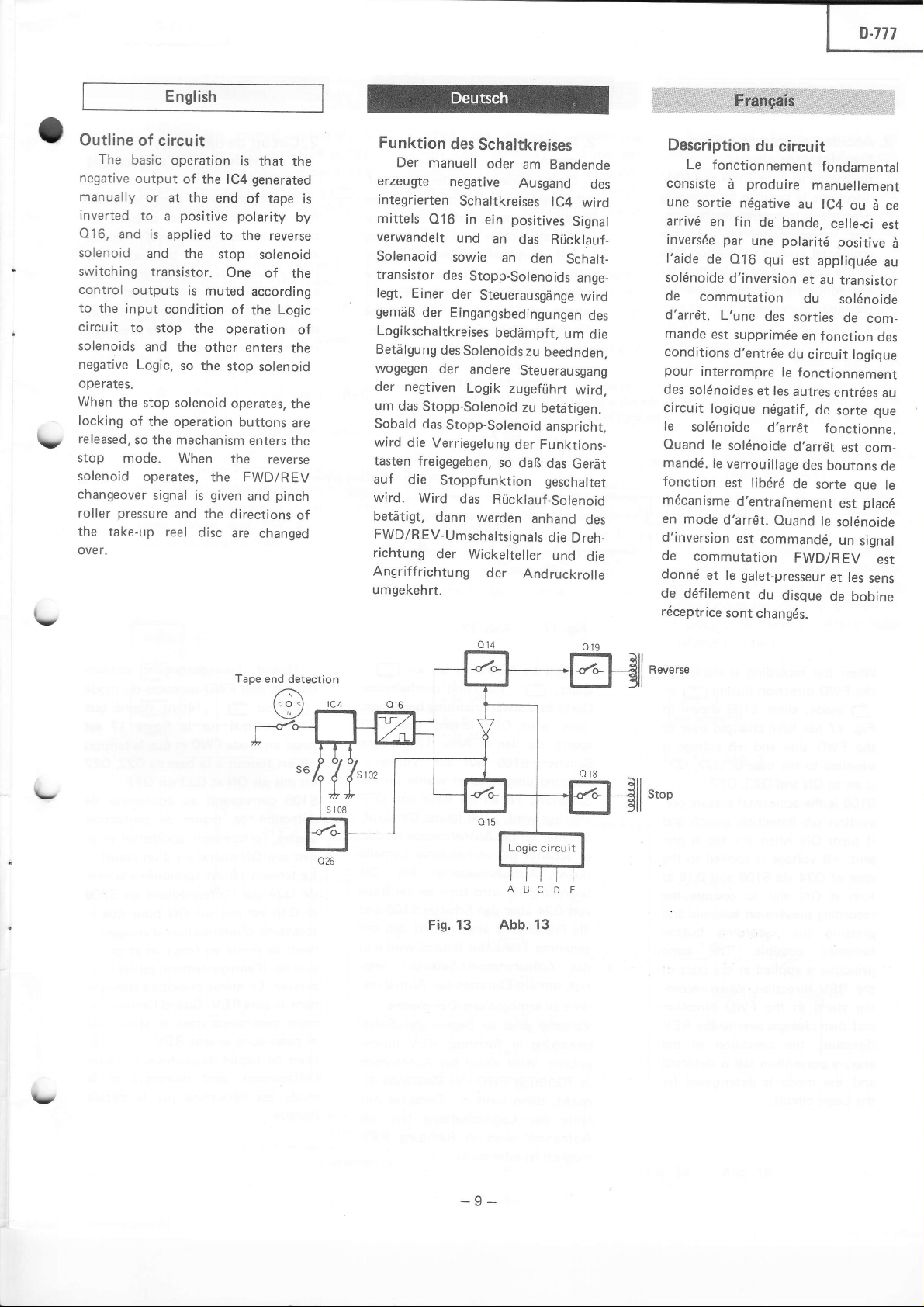
outtine
The
basic
negative
manually
inverted
Ol6,
output
and is
solenoid
switching
control
to
circuit
solenoids
negative
operates.
When
locking
released,
stop
outputs
the
input
to
the
of the
so the mechanism
mode.
solenoid
changeover
pressure
roller
the
take-up
over.
English
of circuit
operation
of
the lC4
or at
the end
positive
to
a
applied
and
the
transistor.
is muted
condition
stop
the
and
the
other enters
Logic.
so the
stop solenoid
operation buttons
When
operates,
signal is
and
the directions
reel disc
is
that
the
generated
of
tape is
polarity
to the
stop
One
according
of
the
reverse
solenoid
of the
Logic
operation
the
stop
solenoid
operates,
the
enters
reverse
the
are
the
the FWD/REV
given
are
and
changed
pinch
by
of
Funktion
Der
erzeugte
integrierten
mittels
verwandelt
Solenaoid
transistor
|egt.
gemóB
of
Logikschaltkreises
Betiilgung
wogegen
der
um
das
Sobald das
wird
tasten
auf
wird.
betetigt,
FWD/REV-Umschaltsignals
richtung
Angriffrichtung
umgekehrt.
des
manuell
negative
Schaltkreises
016
in ein
und
sowie
des
Stopp-Solenoids
Einer
der
der
Eingangsbedingungen
des
Solenoids
der
andere
negtiven
die
freigegeben,
die
Wird
Logik
Stopp-SoIenoid
Stopp-Solenoid
Verriegelung
Stoppfunktion
das
dann
werden
der
Wickelteller
Schaltkreises
oder
am
Bandende
Ausgand
lC4
positives
an
das
Ri.icklauf-
an
den
Steuerausgónge
bediimpft,
zu
beednden,
Steuerausgang
zugefiihrt
zu
betótigen.
anspricht,
der Funktions-
so
daB
das
geschaltet
Riicklauf-solenoid
anhand
die
und
der
Andruckrolle
wird
Signal
Schalt-
ange-
wird
des
um
wird,
Gerót
des
Dreh-
die
des
die
Description
Le
du
circuit
fonctionnement
consiste i produire
une
sortie
nógative
arrivó
en fin
inversóe par
|'aide
de
so|ónoide
de
commutation
d,arrćt.
mande
conditions
pour
interrompre
des
so|ónoides
circuit
ouand
mandó.
Ie
so|ónoide
|ogique
|e
fonction
mócanisme
en
mode
d'inversion
de
commutation
donnć
et |e
de
dófi|ement
róceptrice
de
une
qui
Q16
d,inversion
L,une
des
est
supprimóe
d,entróe
et |es
nógatif,
d,arrót
so|ónoide
Ie
verroui||age
est
|ibćró
d,entrainement
d,arrĆt.
est
commandó,
ga|et-presseur
du
sont
changćs'
bande,
po|aritć
le
ouand
disque
fondamental
manuellement
au |C4
est
et
sorties
en fonction
du
fonctionnement
autres
d,arr€t
des
de
FWD/R
ou
ce||eci
positive
app|iquće
au transistor
du
so|ónoide
de
circuit
Iogique
entrćes
de
sorte
fonctionne.
est com.
boutons
sorte
est
|e
solćnoide
un
EV
et łes
de
bobine
que
signa|
d
com.
des
que
p|acó
est
sens
ce
est
d
au
au
de
|e
\t
fv
Fig. 13
Reverse
Abb. 13
-9-
Page 10
rj
English
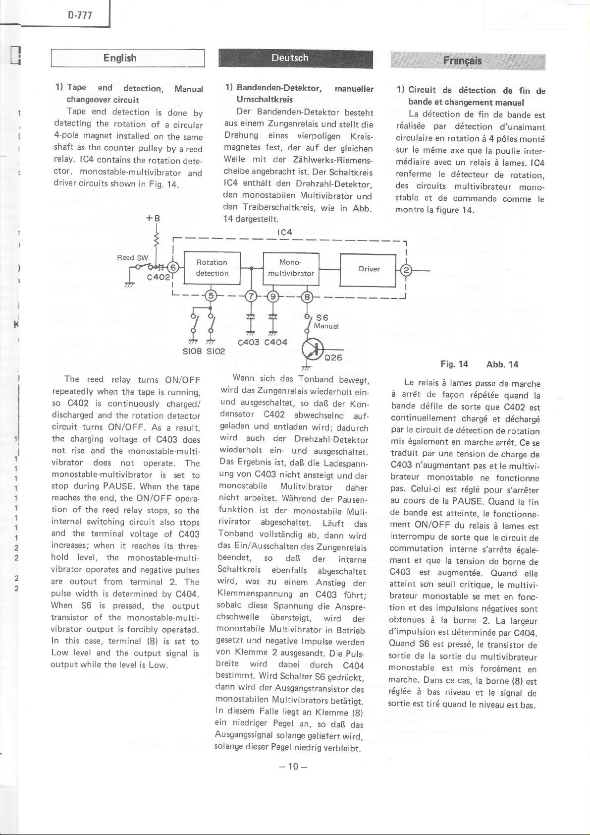
1)
Tape
changeover
t
Tape
detecting
I
4-pole
shaft
relay.
ctor,
driver
end
detection,
circuit
end
magnet
as
the
lC4
detection
the
rotation
installed
counter
contains
is
done
of
a
on
the
pulley
by
the rotation
monostable-multivibrator
circuits
shown
in Fig.
14.
Manual
by
circular
same
a reed
dete-
and
1) Bandenden-Detektor,
Umschaltkreis
Der
Bandenden-Detektor
aus
einem
Zungenrelais
Drehung
magnetes fest,
We||e
cheibe
lC4
den monostabilen
den
14
dargestellt.
eines
vierpoligen
der
auf
mit
der
ZóhIwerks.Riemens.
angebracht
enthiilt
ist.
den
Drehzahl-Detektor.
Multivibrator
Treiberschaltkreis,
Der
manueiler
besteht
und
stellt die
gleichen
der
Schaltkreis
wie
in
Kreis-
und
Abb.
1)
Circuit
bande
La
dótection
róaIisóe
circuIaire
|e
sur
móme
módiaire
renferme
des
circuits
stable et
montre
la
de dótection
et changement
de fin
par
dótection
en rotation
axe
avec un
|e dótecteur
de commande
f
igure
d 4
que
reiais
multivibrateur
14.
de fin
manuel
de
d'unaimant
pó|es
pou|ie
|a
|ames.
d
de
comme
bande
montć
inter.
rotation,
mono-
de
est
IC4
le
lc4
auf_
das
der
der
des
(g)
ein_
der
--"1
I
Le
relais
d arr€t
bande
continue||ement
par
mis
traduit
C403
brateur
pas'
au
de
ment
interrompu
commutation
ment
c403
atteint
brateur
tion
obtenues
d'impuIsion
ouand
sortie
monostab|e
marche.
róg|óe
sortie
de
dófi|e
|e
circuit
óga|ement
par
n'augmentant
monostable
Ce|ui-ci
cours
bande
ON/OFF
que
et
est
son
monostable
et des
56 est
de
Dans
d bas
est tiró
Fis.
14
rópótóe
de
sorte
chargó
dótection
en
marche
tension
est rógló
atteinte,
du
relais
sorte
passe
pas
que
i lames
facon
de
une
de la PAUSE.
est
de
interne
la
tension
augmentće.
seuil critique,
se met
impulsions
la
d
borne
est
dóterminóe
la
pressó,
sortie
|e
du
est mis
ce cas,
la
niveau
quand
et
|e
niveau
Abb. 14
de marche
quand
que
C402
et
dćchargć
de rotation
arr€t.
Ce
de charge
et le
multivi-
fonctionne
ne
pour
s'arr€ter
Ouand
le
la fin
fonctionne-
d lames
le
circuit
s,arr6te
de
borne
ouand
le multivi-
ćga|e-
eIle
en fonc-
nógatives
2. La
transistor
multivibrateur
par
sont
largeur
C4O4.
forcóment
(8)
bor.ne
|e
signa|
est
bas.
|a
est
se
de
est
de
de
de
en
est
de
|
Reed
SW
I
il
I
I
I
1l
i
t'
1
1
1
1
1
1
1
1
2
2
f
2
The reed
repeatedly
so
C402 is
discharged
circuit
the
charging
not rise
vibrator
relay
when
continuously
and the
turns
ON/OFF.
voltage
and the
does not
turns
the
tape
rotation
monostable-multi-
monostable-multivibrator
stop
during PAUSE.
reaches
tion
internal
and
increases;
hold
vibrator
the end,
of the
reed
switching
the terminal
when
level,
the
operates
are output from
pulse
width is
When
transistor
vibrator
In
this
Low level
output
is
56
the
of
output is
case, terminal
and the
while
the level is
When
the
ON/OFF
relay
circuit
voltage
it
reaches
monostable-multi-
and negative
terminal
determined
pressed,
monostable-multi-
forcibly
output
ll-rl
ON/OFF
is running,
charged/
detector
As
a
of C403
operate.
is
the
stops,
also
of
its
2. The
by
the output
operated.
(8)
is
signal
Low.
sroS sro2
result,
does
The
set to
tape
opera-
so
the
stops
C403
thres-
pulses
C404.
set to
is
c404
c4o3
Wenn
sich
das Tonband
wird
das
Zungenrelais
und
ausgeschaltet,
densator
geladen
wird
wiederholt
Das
ung
monostabile
nicht
funktion
rivirator
Tonband
das
beendet,
Schaltkreis
wird,
Klemmenspannung
sobald
chschwelle
monostabile
gesetzt
von
breite
bestimmt.
dann
monostabi|en
In
diesem
ein
niedriger
Ausgangssignal
solange
C4O2
und
entladen
auch
der
ein-
Ergebnis
von
C403
ist,
nicht
Mulitvibrator
arbeitet.
ist
der
abgeschaltet.
vo||stóndig
Ein/Ausschalten
so
ebenfalls
was
zu
diese
Spannung
ribersteigt,
Multivibrator
und
negative
Klemme
wird
2 ausgesandt.
wird
dabei
Wird
der
Ausgangstransistor
Mu|tivibrators
Falle
Pegel
solange
dieser
Pegel
Schalter
s6
Manual
Q26
wiederholt
so
daB
abwechselnd
wird;
Drehzahl-Detektor
und
ausgeschaltet.
daB
die
Ladespann-
ansteigt
Wóhrend
der
monostabile
Lduft
ab,
dann
des
Zungenrelais
daB
der
abgeschaltet
einem
an
Anstieg
C403
die
wird
in
lmpulse
Die
durch
gedrtjckt,
56
betótigt.
liegt
an
Klemme
an,
so
daB
gel
iefert
niedrig
verbleibt.
bewegt,
der
Kon-
dadurch
und
daher
Pausen-
Muli_
wird
interne
frihrt;
Anspre-
Betrieb
werden
puls-
C4O4
das
wird,
-10-
Page 11
T
p.777
|
English
When
controlled
the
changed
mode recording
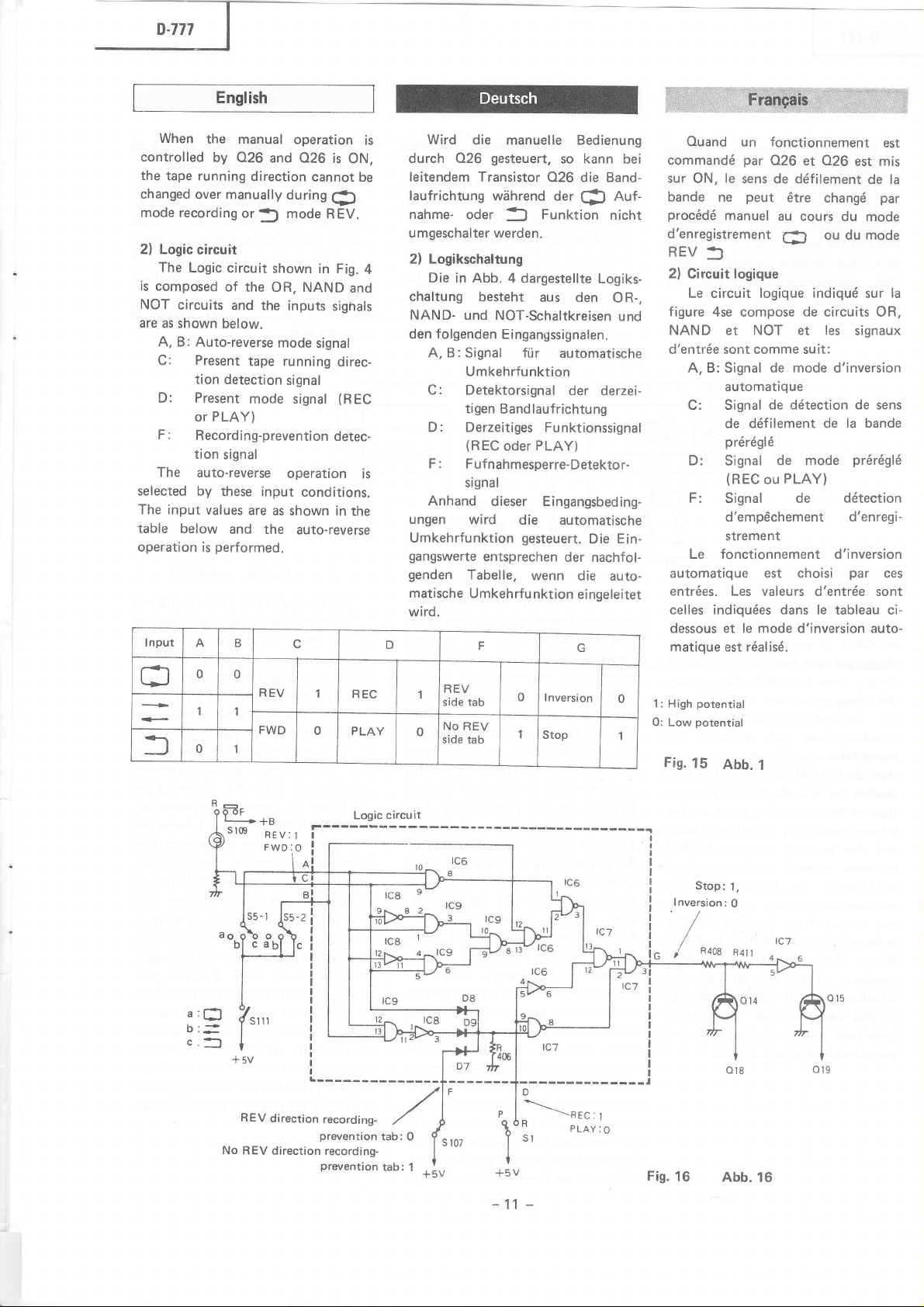
2) Logic
The
is composed
NOT
are as
A, B: Auto-reverse
the
by 026
tape running
over manually
circuit
Logic
circuits
shown below.
C: Present
tion detection
D: Present
PLAY)
or
F:
Recording-preventiondetec-
tion
The
auto-reverse
selected by
The input
table below
operation is
I npul
values
performed.
A
manual operation
and 026
direction cannot
during
or
mode
J
circuit
shown
of the
OR,
NAND
and
the inputs
mode
tape running
signal
mode signal
signal
operation
these
input
conditions.
are
as shown
and the
B
auto-reverse
is
Ęl
REV.
in
sighals
signal
ON,
Fig.
and
direc-
(REC
in
the
be
is
Wird
durch 026
leitendem Transistor
Iaufrichtung
nahme-
umgeschalter werden.
2) Logikschaltung
4
Die in Abb.
chaltung
NAND-
den folgenden
A,
C: Detektorsignal
D: Derzeitiges Funktionssignal
is
F: Fufnahmesperre-Detektor-
Anhand
ungen
Umkehrfunktion
gangswerte
genden
matische Umkehńu
wird.
D
die manuelle Bedienung
gesteuert,
wóhrend
oder
3
4 dargestellte
besteht
und NOT-Schaltkreisen
Eingangssignalen.
B: Signal fiir
Umkehrfunktion
tigen
Bandlaufrichtung
(REC
oder
signal
dieser Eingangsbeding-
wird
entsprechen
Tabelle,
r
so kann
026 die Band-
der
Funktion
aus
automatische
der derzei-
PLAY)
die
automatische
gesteuert.
der nachfol-
wenn
nktion einge|eitet
(i
Logiks-
den
Die
die
u
bei
Auf.
nicht
R-.
O
und
Ein-
auto-
Ouand
commandó
sur
oN,
bande
procódó
d'enregistrement
REV
2)
Circuit logique
Le circuit
figure
NAND
d'entrće sont comme suit:
un fonctionnement
par
0.26
|e
sens de dćfi|ement
peut
ne
manue|
026
et
6tre
changó
au cours
ou du mode
Ę)
du
:l
Iogique
4se compose de circuits OR,
NOT et les
et
indiquó sur
A, B: Signal de mode d'inversion
automatioue
C: Signa| de
dótection de
de dófi|ement de
próróg|ó
D:
F:
Signa|
{REC
Signa|
mode
de
PLAY)
ou
de dótection
d'emp6chement d'enregi-
strement
Le f
onctionnement
d'inversion
automatique est choisi
entróes. Les vaIeurs
ce|les indiquóes
dessous et le mode d'inversion
matique est róaIisó'
d,entróe
dans |e
tableau ci.
est
est mis
de
par
mode
signaux
sens
|a bande
prórógló
par
ces
sont
auto-
la
|a
LJ
f
U
1
0 1
:
a
l--l
b:*
c.l
0
1
aO
b
REV
No REV
REV
FWD
rwo:o
o
'l
0 PLAY
!
direction
direction recording-
recording-
prevention
REC
tab:
REV
0
I
side tab
No
REV
side
tab
J/an-
0 Inversion
Stop
tca
lc6
|
J
>.
r2
0
1
f-;v
l-rcr
ll
lr
1 : High
0:
3a
I
Low
Fig.
I nversion
/
potential
potential
15
Stop:1,
R4o8
Abb.
:
0
R4n
l
Y !
rc7
D
Pl
0
1'
ł
+5v
\REC:
p
"
sl
PLAY:
I
-__-,i
O
!
I
Fig.
16
Abb.
16
-11
-
Page 12
English
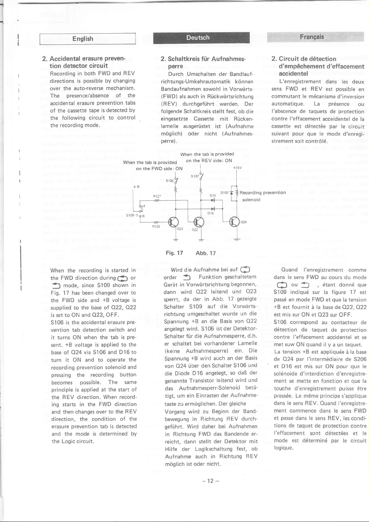
2. Accidental
tion detector
Recording
clirections
auto-reverse
the
over
presence/absence
The
accidental
cassette
the
of
following
the
recording
the
erasure
circuit
in both
possible
is
erasure
tape is
circuit
mode.
Preven-
FWD
and
by changing
mechanism.
of the
prevention
detected bY
to control
REV
tabs
2.
Schaltkreis
f0r
Aufnahmes-
perre
Durch Umschalten der Bandlauf-
richtungs.Umkehrautomatik kónnen
Bandaufnahmen sowoh| in Vorwórts.
(FWD)
als auch in Rilckwdrtsrichtung
(REV)
folgende
eingesetzte Cassette
lamelle ausgeriistet ist
móglich) oder nicht
perre).
durchgefiihrt
Schaltkreis stellt
is
tab
the
When
werden. Der
fest,
ob die
Rticken-
mit
(Aufnahme
(Auf
nahmes.
Provided
2. Circuit de dótection
d'emp6chement
d'effacement
accidentel
L'enregistrement
sens FWD
commutant
et REV est
|e
automatique.
l'abscence
contre l'effacement
cassette
suivant
strement soit contrÓ|ó.
de taquets
est dótectóe
pour
dans
mćcanisme
La
acceidentel
que
le mode
prósence
possible
d,inversion
protection
de
Ie circuit
oar
les deux
en
ou
de
d'enregi-
la
When the
the
1l
Fig.
the
supplied
is set to ON and
S106 is
vention tab
it
turns
sent.
base of
turn
recording
pressing
becomes
principle
the REV
ing
and
recording
FWD direction during
mode, since
has been changed
17
FWD
side
to the
the
accidental
detection switch
when the tab
ON
+B
voltage
A24 uia 5106 and
it ON
and
prevention
the
possible.
is applied at
direction.
in the
starts
then changes over
is
started
5109 shown
+B
is
applied
voltage
422, Q22
erasure
and
base of
O23, OFF.
to operate
solenoid
recording
The same
the
When record-
FWD direction
to the
direction, the condition
erasure
and the
the Logic circuit.
prevention
mode is
tab is
determined by
(3
or
over to
pre-
and
pre-
is
to the
D 16 to
the
and
button
start
REV
of the
detected
in
in
of
Fis. 17
Wird
order
Gerót
dann
is
sperrt,
Scha|ter
richtung
Spannung
angelegt
Schalter
er schaltet
(keine
Spannung
von A24
Diode
die
genannte
das
tigt,
taste
Vorgang
bewegung
gefiihrt.
in Richtung
reicht, dann
Hilfe der
Aufnahme
móg|ich
Abb. 17
Aufnahme
die
Funktion
3
Vorwiirtsrichtung
in
O22 leitend
wird
der
da
S109
umgeschaltet
+B
an die
wird. S106
fiir die Aufnahmesperre,
bei
Aufnahmesperre)
+B
wird auch
den Schalter
iiber
D16 angelegt,
Transistor
bei auf
geschaltetem
begonnen,
in Abb.
auf
vorhandener
17
die
wurde
Basis
der Detektor-
ist
an
so
leitend
und
Vorwórts.
von
ein.
der
S106
wird
Aufnahmesperr-Solenoid
Einrasten
ein
um
zu ermóg|ichen.
wird
Richtung
in
Wird daher
FWD das
stellt
der Aufnahme-
Der
Beginn der
zu
bei Aufnahmen
der Detektor
gleiche
REV durch-
Bandende er-
Logikschaltung
Richtung REV
in
auch
nicht.
oder
ist
F
O23
gezeigte
un die
O22
d.h.
Lamelle
Die
Basis
und
der
daB
und
betó-
Band'
mit
fest, ob
Ouand
dans le
cJ
S109
passó
+B
est
est
mis sur
S106 correspond
dótection de
contre
met
suw
La
tension
de Q24
et
D16 est mis
so|ónoide d,interdiction
ment
touche
pressóe.
dans le
ment commence
passe
et
tions de
l.effacement
mode est
logique.
l'enregistrement
FWD
sens
ou
3
indiquó
en mode
fournit
ON et O23
au cours du mode
ótant
,
sur Ia f igure 17
FWD
et
la
i
base dea22,O22
au contacteur de
taquet
l'effacement
quand
ON
+B
par
l,intermódiaire de
accidentel et se
y
il
est
app|iquóe
sur ON
se mette en fonction
d,enregistrement
Le
sens
principe
mórne
REV. Ouand
dans le sens FWD
dans le
taquet de
sens
sont
REV,
protection
dótectóes
dóterminó
donnó
que
Ia
sur OFF.
protection
de
un
a
taquet.
ż
pour
d'enregistre-
et oue la
pu
isse
s,app|ique
l'enregistre-
les condi-
par
|e circuit
comme
que
est
tension
|a
base
5206
que
ótre
contre
et Ie
le
-12-
Page 13
English
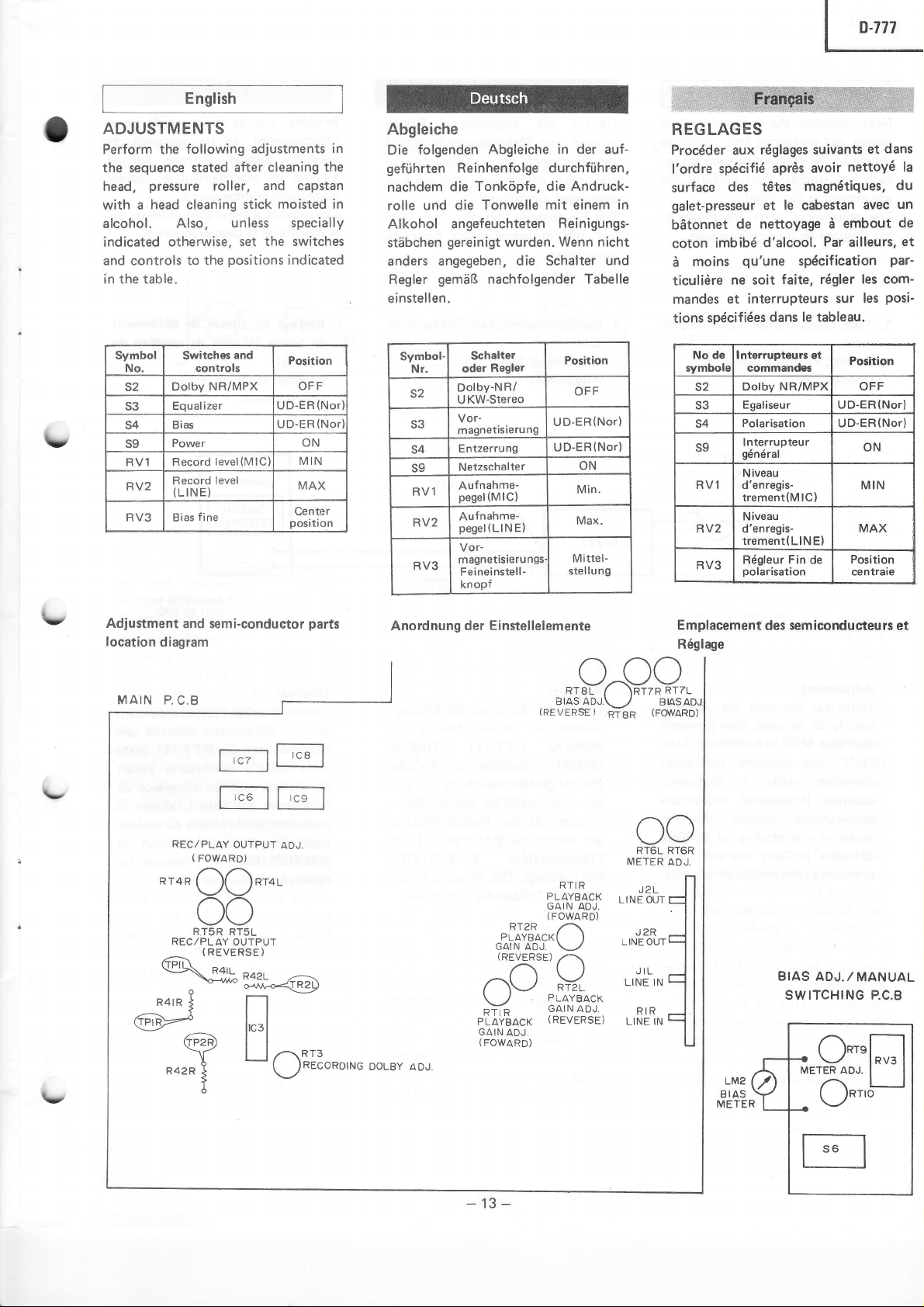
ADJUSTMENTS
Perform the
the sequence
head,
with a
alcohol.
indicated
and controls
in the table.
Symbol
No.
s2
s3
s4
s9
RV1
RV2
RV3
following
stated
pressure
head
cleaning
Also.
otherwise,
to the
Switches
controls
Dolbv
Equalizer
Bias
Power
Record
Record
(LINE)
fine
Bias
adjustments in
after cleaning
roller, and capstan
stick moisted in
unless specially
set the switches
positions
and
NR/MPX
level(M lC
level
indicated
Position
OFF
UD-EB
UD-ER
ON
MIN
MAX
Center
position
(Nor
(Nor
the
Abgleiche
Die
folgenden
Abgleiche in
geftihrten Reinhenfolge durchfiihren,
Tonkópfe, die Andruck.
nachdem
rolle
die
und die
Tonwelle mit einem in
Alkohol angefeuchteten
stebchen
gereinigt
anders angegeben,
instellen
Symbol.
Nr.
s2
s3
s4
s9
BV1
RV2
RV3
gemiiB
.
Regler
e
wurden.
die Schalter und
nachfolgender Tabelle
Schalter
Regler
oder
Dolby-NR/
U KW-Stereo
Vor-
magnetisierung
(M
pegel
Aufnahme-
(LlN
pesel
Vor-
ei neinstel
F
knopf
lC)
ng
E)
ngs
-
I
E ntzerru
Netzschalter
Aufnahme-
magnetisieru
der
auf-
ReinigungsWenn nicht
Position
OFF
UD-ER(Nor}
UD-EB(Nor)
ON
Min.
Max.
Mittel-
stellung
REGLAGES
Procćder aux
|'ordre
surface
galet-presseur et le cabestan
batonnet
coton
moins
ó
ticulidre
mandes et
spócifióes
tions
No de
svmbole
s2
s3
s4
s9
RV1
RV2
RV3
róglages suivants
avoir
spócifió
aprds
des t6tes
magnótiques,
de nettoyage d
imbibó
d,a|cool.
qu,une
ne
soit
interrupteurs
dans |e tab|eau.
tnterrupteurs ot
commandes
Dolby
Eqaliseur UD-ER{Nor}
Polarisation
nterrupteur
I
gónóraI
Niveau
d'enregistrement{M
Niveau
d'enregis-
trement(LlN E)
Róg|eur
polarisation
Par
spócification
faite, róg|er
sur
NR/MPX OFF
lC)
Fin
de
nettoyó
embout
UD-ER(Nor)
dans
et
avec
ai||eurs,
|es com-
les
Position
ON
MIN
MAX
Position
centraie
la
du
un
de
et
par.
posi'
l-
\-
ty
Adjustment
location
diagram
MAIN P.
"to"
qi\*K-@)
and semi.conductor
C.B
|-'";ll-,;l
REC/PLAY
REC/PLAY
OUTPUT
(
FOWARD)
OO*-o.
nn
\-/\-/
RTsR RTsL
OUTPUT
(
REVERSE
)
n
l"l
LJ
pańs
ADJ
ORIS"RDTNG
Anordnung
DoLBy aDJ
Einstellelemente
der
oo
RTIR
PLAYBACK
GAIN
AOJ.
(FOWARD)
Emplacement
RógIage
LM2
IAS
B
METER
des sem iconducteu rs
BIAS
ADJ./
MANUAL
SWITCHING P.C.B
.o*,m
MErER aDJ.
I I
O*''o!
et
-
13
-
Page 14

Next,
connect
source
and
shown
in
each
adjustment;
adjustment
The
adjustment
the
diagram
English
the
measuring
the
connection
as described
parts
on the
indicated
instruments
perform
then
are shown
previous
signal
diagram
page.
for
the
Danach
as
in
que||en
der Diagramme
stellungen
stellu ngen
Die Einstellteile
auf der
entnehmen.
die
angegebenen
und
MeBinstrumente
filr
die
anschlieBen
durchfiihren.
sind
vorhergehenden
einzelnen
und
dem
Diagramm.
Seite
Signal-
gemóB
Ein-
die Ein-
zu
Brancher
ensuite
recommandóe
mesures
schóma
|es
Les
|e
schóma
róg|ages
organes
comme
de
branchemgnt
comme
d róg|er
de |a
la
et
page
sourcc
Ies
łpplreiIs
indiqtrć
dócrit.
sont
indiqućs
próc&lctrtc.
do
signal
dc
sur
rt rółłistr
rur
1€
1.
Tape
speed
ment
Setting:
Connection:
Adjustment:
Warm
up
mately
test
Hz*)
20
tape
and
deviation
counter.
semi-variable
motor
urement
for
(3150H2*).
at the
(motor
Playback
3000Hz(t1
the
unit
minutes;
MTT-1
measure
with
lf
required,
resistor
a reading
Carry
middle
speedl
mode
MTT-I
11
59g2ł1
for
then
1 1,
3000H2(31b0
the
a frequency
adjust
of
out
the
of
adjust-
approxi-
playback
speed
the
on
the
3000H2
meas-
the taoe.
1.
Bandgeschwindigkeit
zah!)
Einstellu
Anschliisse:
Abgleich:
Das
warmlaufen
Priifband
(3150H2*)
chwindigkeitsabweichung
ng:
Gerót
Wiedergabe
fiir
etwa
lassen;
MTT-I11,
abspielen
em Frequenzzdhler
erforderlich,
am
Motor
Frequenzzóh|er
Hz*)
Mitte
des
nachjustieren,
anzeigt.
Tonbandes
den
Regelwiderstand
3'000Hz(3150
Die
Messung
(Motordreh-
20
Minuten
danach
3.000H2
und
die
mit
messen.
bis
in
vornehmen.
das
Ges-
ein-
Wenn
der
der
1. Róg|aę
dc bandc
moteur)
Róg|age:
Branchement:
Róg|age:
Laisser
environ
bande
de
(Vitcrsc
Mode
chauffer
20
de
contróle
vitesse
minutes puis
Hz(3150Hz*)
de
vitesse
fróquence.
rósistance
pour
avec
Au
semi.variable
obtenir
une
3000H2(3150H2*).
mesures
en
milieu
Ćo
de
|ecture
*
According
DIN
l,appareil
MTT.I
et
mesurgr
un
contp${łr
besoin,
indication
Effoctuer
de
bandc.
de ćÓfi|cnłnt
ldrrr
/t5
5OO.
ajuster
ou
to
pcndant
lire
une
1
l,
3oo0
l,ócart
moteur
*
de
|a
de
tes
-14-
Page 15

2.
Head
Setting:
Connection:
English
azimuth
Playback
MTT.1I4
10 kHz
adjustment
mode
2. Tonkopfazimut
E instellung:
Anschliisse:
Wiedergabe
2..Róglage
tique
Róglage:
Branchement:
Top
view
Record/Playback
d,azimuth
Mode
de |ecture
of
head
de
t€te
magnó-
lrr
ły
{-
Adjustment:
Use the
jig
nearest
To
tilt
has
playback
l0kHz) in
tion
so that
channels is
screw A
tion in
FORWARD
and check
the
Check that
between
tions is
ment,
back
is within 2 dB when
the test tape is
HITACHI
and
instructions.
HITACH
obtain
the
and
azimuth.
to be
done
the
the
and adiust
the
max. Adjust
for
the REVERSE
the
direction
again
FORWARD
channels
within
and
the difference
level between
I
office.)
correct
This
alternately.
test
FORWARD
adjusting
output of
same way
that
direction
level
the
3dB
played
head
adjusting
(Consult
head
height,
adjustment
(MTT-114,
tape
screw B
adjusting
adjustment
the output in
is
max.
difference
in both
after adjust-
in
sides A and B
the middle
back.
direc-
both
direc-
as in
direc-
play-
of
Abgleich:
Die
stellehre
sich an
H ITACH
verwenden
die
niichste
Vertretung).
Tonkopfhóne,
und
erhalten,
einige
Das
Richtung
und
daB
Maximum
stellschraube
REVERŚE
R ichtung
und
der
Azimuteinstellung
muB
Male
wiederholt
Priifband
MTT-l
FORWARD
die
Schraube
der
Ausgang
annimmt.
g|eich
FO
RWAR
nochmals
Ausgang
FORWARD
aufweist.
Nach
diesem
kontrollieren,
zwischen
beiden
dB
3
Wiedergabepegel
Seiten
von
2 dB
des Pr0fbandes
daB
den
beiden
Richtungen
liegt;
der
A
und
liegen,
abgespielt
l-Tonkopf-Ein-
(wenden
HITACHI-
Um
Tonkopgneigung
dieser
B
beider
richtige
Abgleich
werden.
14,
1OkHz,
abspielen
so einstellen,
Kanó|e
Die
A
fiir
Richtung
wie
D
einjustieren
kontrollieren,
in
Richtung
ein
Abgleich
B
Maximum
ist
der
Unterschied
Kanó|en
innerhalb
Unterschied
zwischen
muB
innerhalb
wenn
die
wird.
ein
Ein-
fiir
dal3
von
im
den
Mitte
Sie
z.)
zu
in
Róglage:
Uti|iser
tóte
tions
HITACHI
vous).
prócis
l'inclinaison
róg|age
in
ment.
Lire la
10kHz)
et
que
maximum.
róglage
bande dans
pour
dans |e
une
le
Vórifier
entre
sens et voir
moins de
vórifier |a
reproduction
si elle
en
|e gabarit
H|TACHI
(consulter
le
Pour
de
doit
bande
dans
ajuster |a
la
sortie
A
obtenir le
sens FoRWARD
nouvelle
FORWARD
sens
Ia
les
canaux
3 dB
diffćrence
correspond
milieu
de bande
de
róg|age
et
lire
|es
le
plus
proche
obtenir
|a
hauteur
et
€tre
fait
d'essai
le sens FORWARD
vis
de róg|age
aux
deux
Ajuster
en faisant
le
sens REVERSE
m6me
fois
si
diffórence
si
elle correspond
aprds |e
entre
d moins
d'essai
de
un
de
l,azimuth,
a|ternative-
(MTT-I
canaux
la vis
dófiler
rósu|tat
et vórifier
la
sortie
est
maximale.
de
dans les
de niveau
A et
B et voir
de
lue.
instruc.
service
chez
rógIage
t6te,
14,
pour
B
soit
que
dans
niveau
deux
róg|age;
2 dB
de
ce
de
Ia
d
de
-
15
-
Page 16

English
Playback
3.
adjustment
Setting: Recording/Playback
Connection:
output and
mode
3.
VU meters
Wiedergabepegel
Einstellung:
Anschliisse:
F
MTT.I50
4OOHz.2Om Moxwell
und Pegelmesser
Aufnahme/Wieder-
gaoe
LINE lN
Dummy
Iood
jock
3. Róglage de niveau
lecture et d'indicateurs
Róg|age: Mode de enregistrement/
I ectu re
Branchement:
TPI
L,R
de
sortie de
de niveau
7
v
Adjustment:
1)
Set
the record
400H2
signal into LINE
adjust the
output voltage at TPl(L, R)
o.775V.
2)
Then, adjust
the meter
Dolby marks
the
to the
Set
3)
Play
back the test
150, 400H2,
FORWARD direction
the
adjust
meter
mark
RT1(L, R)
indicates the DOLBY
(
Dn
mode.
attenuator
RT6(L,
indicators
(
Dn
playback
mode
tape
20 mMaxwell)
so that the
).
Adjust RT2(L, R) in the
REVERSE
same way.
direction in
Feed
lN
and
so that
R) so that
deflect
)
(MTT-
and
the
u
Abgleich:
a
1)
Das Gerór auf Aufnahme
Ein
schalten.
is
den LINE
speisen
ungsglied einstellen,
Stiften
to
in
gangsspannung
liegt.
an
2)
Danach
so daB die
Instrumente
Markierung
gen.
3)
Das
schalten.
Prtifband
Ein
Gerót auf
Hz. 20
FORWARD abspielen
tung
RTl(L,
die
instrumente
Markierung
gen.
Auf die
Weiseist
REVE RSE abzugleichen.
tung
400H2
Signal an
lN Buchsen ein-
und den Dómpf-
bis
an den
TP1(L. R) eine Aus-
von
0,775V
RT6(L, R) einstellen,
Anzeigenadeln
bis zue Dolby-
(
)
Dn
Wiedergabe
(MTT-150,
Maxwell)
m
R)
so einstellen,
Zeiger der Anzeige-
bis zur Dolby-
(
Dn
gleiche
RT2(L,
R) fiir Rich-
ausschla-
in
ausschla-
)
Art und
der
400
Rich-
und
daB
Róglage:
,|
)
Róg|er |,appareil
d'enregistrement.
une signa| de 400Hz
de ligne LINE lN
|,attónuateur
obtenir
de O,775Y
R).
2)
Ajuster
pour
cateurs viennent
une
aux broches TP1(L,
ensuite
que
les
symbole(D[
3)
Róg|er en mode de
Lire la banded'essai
4OOHz,20m
FORWARD et ajuster
sens
(L,
RTl
vienne se
DOLBY
(L,
en
R)pourque
placer
(
R)
dans
procódant
Dl
en mooe
Appliquer
d |'entrće
et
ajuster
de
signaux
tension de
aiguilles d'indi-
se
)Dolby.
Maxwell) dans
sur
)
le
sens
de mime.
sortie
RT6(L,
placer
lecture
(MTT-'l
l'indicateur
le
symbole
Ajuster RT2
REVEBSE
pour
sur
U,
R)
le
50,
le
v
-16-
Page 17

English
ś
J
J
.v
4. Bias
curent, record
ment
Setting: Record
mode
Connection:
Adjustment:
1) Use
2)
HITACHI
tape.
Set to
and feed
LINE lN
attenuator
meters
3)
Next.
reduce
and record
signals
direction.
Adjust
recording
playback
the
l0kHz
of the
Adjust
way in
tion.
4)
Record
FORWARD
in the
Adjust RT4(L,
ing
recording
that the
the
section with
recorded
In
the REVERSE
also. adjust RTS(L,
same way.
SG
14OOHz
the
a 400H2
of the
adjust
the
in
RT7{L.
and
signal
1
kHz
RT8(L,
the
signal
a
playback
is
OVU.
leve!
ing/Pl
ayback
I
j
UD-ER
recording
signal into
and adjust
so
that the
set indicate
the
attenuator
input
by
lkHz
and
the
FORWARD
R)
repeating
playback
output
is
within
signal
output.
R)
in the
REVERSE
of 400H2,
direction.
R) while
playback
and
output
the signal
direction,
R)
adjust-
..O
{
C-90
mode
the
VU
0VU.
-20dB
10kHz
so
that
of
the
ij.5dB
same
direc-
0VU
repeat-
in the
to
so
of
4. Vormagnetisierungsstrom,
nahmepege!
E
instellung:
Anschliisse:
Auf nahme/Wieder-
gabe
LINE
Dummy
tood
47K
ATT
G
600
e
VTVM
Abgleich:
HITACHI
1)
Cassette
2) Den
Monitor-Schalter
tion
40OHz
Buchsen
Danach
abgleichen,
des
Gerótes
0VU
Danach das Dómpfungsg|ied
t)
abgleichen,
gangspegel
duziert
sowie ein 10-kHz-Signal
Richtung FORWARD
men.
holter Aufnahme
gabe
Wiedergabepegel des
Signats
gegentiber
pegel
4) Ein
400H2,
R ichtung FO RWA
Die Atrfnahme
wiederholen und
abg|eichęn, daB der Ausgang
der
betrógt.
Auf die
RTs(L, R) filr
REVERSE
LINEOUT
jock
UD.ER
verwenden.
SOURCE
Signal
das DómpfungsgIied
anzeigen.
stellen
an den
einspeisen.
daB
die
einen PegeI
daB
um
-20
und
wird
RT7(L,
so abgleichen, daB
innerhalb
liegt.
bespielten Stelle
R)
und Wieder-
von
dem 1-kHz-Signal-
0
VU
RDaufnehmen.
undWiedergabe
RT4(L,
gleiche
Art
einstellen.
Auf-
jock
lN
l
C-90
posi-
auf
und
ein
LINIE
VU-Meter
von
der Ein-
dB re-
ein
1-kHz-
aufneh-
bei wieder-
der
10-kHz-
+1,5
dB
Signal
R)
VU
0
und Weise
Richtung
lN
so
so
in
so
an
in
D-177
4. Reglage
ment et de courant
Róg!age : Mode d,enregistrement/
Branchement:
de niveau d'enregistre-
polarisation
de
lectu re
c-[
4
Róg|age:
1) Utiliser
UD.ER
2)
RógIer
trÓ|e
Appliquer
la borne
|,attónuateur
mdtres
Ensuite,
3)
pour
de
signaux de
le
Ajuster
les modes
de lecture
lecture
n,excóde
sortie
Ajuster
faQon
4) Enregister un
OVU
Ajuster
rópćtant
ment
sortie d la lecture
signaI enregistró
OVU.
Róg|er óga|ement
|a
REVERSE.
une
bande
C.90.
|,interrupteur
position
|a
sur
un
signal
LINE
pour
indiduent
ajuster
róduire |e niveau
dB et
-20
lkHz et 1OkHz
FORWARD.
sens
RT7(L'
d'enregistrement
pour
du signal de
pas
du
signal
RT8(L'
le
dans
sens REVERSE.
le
dans
m€me
sens FORWARD.
RT4(L,
Ies modes
et de lecture
faęon
de 400H2
lN
que
0VU.
|,attónuateur
enregistrer
R) en
la
t1,5
de
lkHz.
R) de |a móme
signal
R)
d,enregistre.
pour que
du
corresponde
RTS(L'
dans le
HITACHI
de
con-
SoURcE.
et
ajuster
Ies
VU-
d'entróe
des
dans
rópótant
sortie de
l0kHz
dB de la
de
400H2,
tout en
passage
R)
sens
i
et
la
du
ó
de
-17-
Page 18

5)
Confirm
CrO2 tapes by
UD-EX
the
to UD-EX
5.
Dolby NR
Setting:
Connection:
English
the
C-90.
Equalizer
(CrO,
adiustment
Recording
SG
adjustments
using
HITACHI
(ln
this
case
and Bias
position.)
)
mode
switches
-o
-OoF
for
set
ATT
5) Die
wiederholen,
UD-EX
wenden
sind
Entzerrung
rung
(CrOr
5.
Dolby
Einste!lung:
Anschliisse:
I
I
J
o
Einstellung
wobei
C-90
Tonband
(fiir
ist
die
BandsortenwóhIer
und
auf Position
zu
stellen).
)
NR-Abgleich
Aufnahme
LINE
Dummy
Iood
47K
500
f0r
CrO2-Band
HITACHI
zu
diesen
Abgleich
Vormagnetisie-
UD_EX
jock
lN
L\
ver-
flir
D-777
5)
S,assurer
les
sont
bande
(Róg|er
sation
position
effectuer
5.
Róglage
Róg|age:
Branchement:
TPz
que
bandes
au
valables
C-90
les
sć|ecteurs
et
d.ógaIisation
UD-EX(CrOz
ce
contrÓ|e).
de
do|by
Mode
d,enregistrement
H|TACHt
L,R
I VTVM
@
L:9199!J
{
{
|es
róg|ages
chrome
en
utilisant
NR
(CrO,
UD-EX.
po|ari.
de
sur
)
pour
)
une
Ia
pour
a
Adjustment:
Set to
5kHz
adjust
voltage
the
signal
the attenuator
of
-30.4dBm.
NR switch
that
the
becomes
Bias
6.
Setting: Recording
1)
meter
Adjust
-22.4
adjustment
meter
when
the bias
knob
is
in its
2)
Adjust
meter
bias
turned
3) Next,
indicates
adjustment
counterclockwise
RT10
indicates
f ine
fully
check
:
record
into
TP2L,
put
Next,
ON
and
voltage
!O.25dBm.
mode
RT9
so that
indicates
fine
center
so
adjustment
clockwise
that
the bias
with
-5
knob
(-).
Feed
mode.
LINE lN
so that
B
oecomes
the Dolby
adjust RT3
of TP2L,
the b,ias
the
center
adjustment
position.
that the bias
+5
with
knob
(+),
meter
the bias fine
turned
fullv
and
the
the
,Ąbg|eich:
a
Das Gerót auf Aufnahme
Ein
SkHz Signal an der LINE lN
Buchsen einspeisen
gangspegel
einstellen,
so
Spannung an den Prtifpunkten
so
R
TP2L, R
Danach
Position
auf
einjustieren, bis die
Pri.ifpunkten
den
t0.25dBm
Abgleich des
6.
Instruments
Einstellung:
1) RTg
Anzeigenadel des Vormagneti-
sierungs-lnstrumentes in Mit-
telstellung
Vormagnetisieru
tellregter
gebracht
2) RT10 so
Vormagnetisieru
+5
magnetisierungs-Fei
regler bis
Uhrzeigersinn
(+).
Danach sicherstellen, daB das
3)
Vormagnetisieru ngs- I nstru ment
-5
m agnetisieru ngs-
regler ist
den Uhrzeigersinn
wird.
-30,4dBm
-
den Dolby-N
ON
stellen und RT3
TP2L, R
betrógt.
Vormagnetisierungs-
Aufnahmefu nktion
so abgleichen. daB die
steht. wenn der
in
wird.
abgleichen, daB das
anzeigt,
anzeigt, wenn der Vor-
wenn der Vor-
zum
zum Anschlag
scha|ten.
und den Ein-
daB die
betrógt.
R-Schalter
Spannung
ngs- Fe
ine ins-
Mittelstellung
| nstru
ngs-
neinstel l-
Anschlag im
gedreht
Feineinstell-
(-)
gedreht
-22,4
ment
wurde
gegen
Róglage:
RógIer
d'enregistrement
signal
et
tension
-30.4dBm.
an
rupteur
ajuster RT3
TP2L, R
dBm.
6.
Róg|age
tion
Róg|age
1)
.
cateur
place
quand
de
tion
2) Ajuster
cateur
+5
fin
p|dtement
(+).
Ensuite,
3)
polarisation
|e
po|arisation
tournć
|,appareiI
de SkHz
aux
ajuster |'entróe
de
TP2L, R
Ensuite,
Dolbv
pour que
óga|e
soit
d,indicateur
: Mode
d,enreg
Ajuster
RTg
polarisation
de
en
|e
bouton
polarisation
la
centrale.
position
RTl0
polarisation
de
quand
|e
bouton
polarisationest
de la
tournó
voir
si l'indicateur
indique
bouton
vers
de
róg|age
est
gauche (-).
Ia
en
et
appliquer
jacks
LINE
pour
soit óga|e
rćgler
N
R
sur
la
tension d
_22.4!a,25
ż|
po|arisa.
de
istrement
pour
que
vienne
centrale
de
róg|age
est
en
pour
que
indique
de
vers
Ia
..-E
fin
comp|ótement
mooe
que
|,inter.
ON
I'indi-
posi-
l'indi-
róglage
com-
droite
quand
de |a
fin
de
un
lN
se
Ia
rf,_
i
et
U
-18-
Page 19

English
INSPECTION
MECHANISM
Pressure
Measure
when
from
gauge,
be within
of
the
the
the caostan shaft with
in the
350
.l
Torque
Take
up
Fast forward
Rewind
OF
pressure
oressure at the
pressure
playback
+60
gr
35
to
65
75
to 120
75
to 1
20
roller moves
gr-cm
gr-cm
gr-cm
roller
mode. lt
gr.
moment
away
a tension
should
Prtifung
des Laufwerkes
Andruckkraft der Andruckrolle
Die Andruckkraft messen,
druckrolle mit Hilfe
wóhrend
der Tonwelle
Kraft
Prsssure
der Wiedergabefunktion
abgehoben wird. Diese
sollte
350
t60
Copston
shott
rollBr
wenn die An-
Federwaage
einer
Gramm betragen.
Drehmomente
Aufwickelteller 35
Schnel lvorlauf
Riicklauf
75
75
bis
6s
bis l 20
bis 1
2O
grcm
grcm
grcm
von
Inspection
Pression
Mesurer
ga|et-presseur
cabestan.
de tension
mode
correspondre
Couple
Enroulement
Avance
Rembobinage
du
la
Utiliser un appareil
et effectuer
de Iecture.
Erose
Pressure
rapide
du mócanisme
galet-presseur
pressiorr
au moment
se sópare de |,axe de
de mesure
ce contrÓle en
rósultat
de
350
heod
35
a
75
a l2ogrcm
75
a 120
Le
orm
6s
grcm
gr
g.cm
obtenu doit
+60
gr.
o0
le
Back tension
Take
reel 1.O
up
Supply reel
gr-cm
to
3.5
Note:
Measure it in the
rewind mode.
1.0 to
Note: Measure it
gr-cm
3.5
back or fast forward
in the
play-
mode.
Bandzugmoment
AufwickełteIler
Abwickelteller
1.0
bis
3,5
Hinweis:
funktion
1,0 bis 3,5
Hinweis:
oder in
funktion
gr-cm
In
der
Rticklauf-
messen.
gr-cm
In
der
Wiedergabe.
der
Schnellvorlauf-
messen.
Tension
Bobine
rou
lement
Bobine
dóbitrice
de retour
d'en-
1.0
Remarque:
1,0
Remarque:
gr.cm
ó
3,5
d
3.5
La mesurer
gr-cm
La mesurer
de lecture
rapide.
mode de rembobinage.
mode
d'avance
en
en
ou
-19-
Page 20

Braking
force
Take
up reel More
Supply reel More
English
than Sg-cm
than sg-cm
Bremsmoment
Aufwickelteller
Abwickelteller
l)
l)5
5
g.cm
g.cm
Force
de freinage
Bobine
roulement
A"Ui*
dóbitrice
d'en- Plus
de
Sgr-cm
de Sgr-cm
L
Auto
stop
or Auto
Auto stop
Within
I
Note:
LUBRICATION
Lubricate
chine oil
grease
respective
every 1000 hours
normal
them excessively,
come
Lubrication
Motor
Capstan
Pressure
one
to rotating
to sliding
parts
conditions
irregular
shaft
bearing
shaft bearing
roller
or two
because
bearing
revetse
time
S
sec
Time
required
auto stopping
the
tape
to run.
drops
point
or lubricate
point.
Lubricate
listed
below
or
once a
of use.
Avoid
or rotation
of
oil splashes.
Oil
I
has
year
may
or
oil
after
stopped
of ma-
the
once
under
oiling
be-
grease
Automatische
Riicklaufzeit
Bandendab-
for
schaltung
Schmierung
Ein
den Drehteilenund
Schmierfett
tragen.
Tabelle
normalen
alle
mal
vie|
unregeImóBiger
kommen
'onwellenlager
Andruckro llen
AbschaItung
Innerhalb
I
'Hinweis:
oder
zwei
Tropfen Maschinenól
auf
den Gleitteilen
Die in
aufgeftihrten
Verwendungsbedingungen
1.000
Betriebsstunden
pro
Jahr
zu
schmieren.
Ó|
auftragen,
Bandgeschwindigkeit
kónnte.
Schmierpunkt
len
lager
lager
od€r automatische-
5 sek.
von
Erforderliche
Zeit
bis
schalten
sorgung,
Tonband
wurde.
eine
der
Teile
zum
der
Stromver-
nachdem
angehalten
geringe
nachfolgenden
Menge
sind unter
bzw.
Niemals
da es ansonsten
Ó| oder
Fett
Ol
I
Ab-
auf-
ein-
zu
zu
Dólai d'arr€t
matiquo
Arrót
auto.
mal|que
das
GRAISSAGE
an
Mettre
une
machine
mettre
de
coulissantes. Graisser
pidces
respectives indiquóes
au moins une
heures
ou une fois
conditions normales
Eviter
de
rotation
suite d,óclaboussures
Graissage
Palier
d'arbre moteur
d'arbre de cabestan
Palier
galet-presseur
de
automatique et
iMoins
|Remarque:Duróe
ou deux
la
points
graisse
sur les
fois
trop mettre
peut
devenir
d,inversion
de
5
sec.
pour
que
matique
aprds
bande.
soit
|'arr€t de
gouttes
de rotation
sur les surfaces
ou huiler
toutes les
par
an
d'utilisation.
d'huile
irrógu|idre
d,hui
|e.
Huile
auto.
nćcessaire
l'arr6t auto-
obtenu
d'huile
de
ou
les
ci.dessous
1000
pour
des
car la
|a
ó
graisse
ou
HuilePalier
|a
t-
g
-20-
Y-
Page 21

English
I
Adjusting
REVE
RSE selector
l. Move
direction
2.
Align
channel
tion
of the
spring
spring with
Fis.
18.)
the FORWARD/
mechanism
(Refer
at
spring
plate
to Fig.
the tip
and the
the
channel
A.
the hole
set
3l ball,
and fix
the
the
screw.
fully in
18)
of the
posi-
press
channel
(Refer
CHANNEL SET
the
set
to
A
Ir
t
!
SHAFT
Einstellen
R E VE
1. Die Kanalplatte
A
Die
2.
einstellfeder mit
3mm@ kugel in iibereinstimmung
bringen, die
die Kanaleinstellfeder
Schrau.be befestigen
18).
SpRtNG
der FORWARD/
-Schaltvorrichtu
RSE
ganz
bewegen
(siehe
Bohrung am Ende
Feder
HOLE
in
Abb.
18).
der Kanal-
Position
der
andriicken
(siehe
3d
BALL
Richtung
mit
ng
der
und
der
Abb.
CHANNEL
Róglage du
mócanisme
Spelection FORWARD/
REVERSE
1. Dóp|acer
de canal
f
igure
2. Aligner
de
position
Ie ressort
róg|age
la figure
PLATE
1 8).
le
ressort
de la
de
18).
comp|ótement
dans
le sens A
trou en bord
de róg|age
et rćgIer
cana|
de
bille de
Ie
avec la vis.
de
p|aque
la
(voir
de ressort
canaI et Ia
presser
3@,
ressort
(Voir
la
de
'y
.,v
v
3. Bend the
selector lever
FR
the
rectly
and
held
in
when
the selector
FORWARD
thE
directions.
PW SCREW
SOLENOID HOLOER
arms
switch
the
the
left
(Refer
(a,
b)
of
to
adjust it
changes
3l ball
and right
cam
is moved
ANd REVERSE
to Fig.
FR
SELECTORLEVER
the FR
so that
over
cor-
is firmly
holes
19.)
B
SOLENOID
3. Die Arme
hebels abbiegen, um
punkt
einzustellen,
Kugel richtig in den
in
rechten Bohrungen
wenn
FORWARD
bewegt
FR SWITCH
!r'ZtTad%
i
'----t+i
Fig. 18
des
die
wird.
L--
Abb. 18
(a.
b)
des
den
FR-Wahlhebels
daB
so
Nocke
die
linken und
gehalten
in Richtung
und REVERSE
(siehe
Abb. 19)
FR-Wahl-
Schalt-
richtig
3mm@
wird,
PW
SCREW
F
Plier
3.
les
bras
sólecteur
sorte
duise
et
correctement
et
só|ecteur
FORWARD
figure
SELECTOR LEVER
BF
que
le
une
commutation
que
la
gauche quand
est dópIacóe
19)
SELECTOR
(a,
pour
contacteur
bille
de
dans les
et
REVERSE.
CAM
b)
du
|,ajuster
FR
correcte
3l
se loge
trous
la
came
dans
levier
droit
Ies
(voir
de
pro-
du
sens
la
Fis. 19
_21 _
Abb.
19
Page 22

English
.+.
Set the selector
shown
in Fig.
selector lever
apply
move
in this
and
compound
Operate the
5.
FORWARD
tions and
roller,
change over correctly.
above at 70%
6
-
fully
it
position
paint
take-up
9V to the
in direction
it with
(Refer
it.
mechanism in the
and
check that
of the rated voltage.)
Check that the
released from
ference
value: More than
cam to the mode
19
and
turn
clockwise. Next.
solenoid to
B:
with 2
gear
the
PW
screws
locking
screw
to Fig. 19.)
REVERSE
and
oressure-roller
capstan
the
FR
(Check
direc-
pressure-
switch
0.3mm).
the
fix it
the
(Re-
4. Die Nocke in
gezeigte
Wahlhebel
drehen. Danach
von
anlegen, um
Richtung
Bend
PW-Schrauben
'Sicherungslack
Abb.19)
5.
Die Vorrichtung
FORWARD
betótigen
is
die Andruckrolle, das
Zahnrad
richtig
obige Priifung
Nennspannung
Darauf
druckrolle von der
abhebt
mm)
die in Abb.
Position
bringen
im Uhrzeigersinn
eine
6 bis 9 V an das
dieses
B zu
bewegen;
in dieser Position
befestigen
sichern.
in Richtung
und
und darauf achten,
Aufwickel-
und
umgeschaltet werden.
der
FR-Schalter
bei 70%
durchfiihren.)
achten,
(Bezugswert:
daB die
Ton
mehr
und
den
Spannung
Solenoid
ganz
anschlie-
mit zwei
und
mit
(siehe
REVERSE
daB
(Die
der
An-
welle
als
0,3
19
in
Rćg|er
|a came de
mode
indiquó sur
tourner Ie Ievier só|ecteur vers Ia
droite.
tension de
pour
ment dans le
position
les
la
Ę
Mettre |e
Ensuite,
qu'iI
avec
tites avec du compound
f
igure
19).
mócanisme en fonction
dans les
REVEBSE et voir
|,engrenage
seur.
contacteur FR
correctement.
mentionós
tension nominale)
presseur
Ieur
p|us
est Iibóró du cabestan
de rófórence:
sć|ecteur
Ia figure l9
appliquer une
6 d 9V au so|ónoide
dćpIace
se
sens
les vis PW et
sens
comp|óte-
B : le retenir
FOBWAR
galet-pres-
le
si
rócepteur et Ie
se commutent
(Vćrifier
haut
Ies
ż 70% de |a
Voir
si
plus
de
0,3mm)
sur
peindre
(voir
D et
points
galet-
le
(va.
le
et
en
e
\L.
-22-
!-
Page 23

p.777
|
e
,9
htsvŁHsE
FOWARD
€
BLOCK
DIAGRAM
_9dB
:
NOR
CrO" :-6dB
FeCr :
-45d8
tcl
L
HA-t 406
-33d8
(
-26d8
RV2
RECORD
LINE
)
RECORD
Rr'1
MVt2
SWITCHING SWITCHING
2SC1 7 4
2SD45678
EO SWITCHING
HV12
VR3
SWITCHING
HVl2
03L
o25
1s2473
COUNTER
ELECTROMOTIVE
REVERSE
{L-----
U
FOWARD
J
\--)'-
X
nJslos
CURRENT
rs)473
couNTER
cURRENT
CHECK
I
I
Q24
2SCr1612WTC
swtTcHtNG
PROTECTION
OUTPUT
ntó
,\
REC EQ AMP
R]20
102
] SR34
COUNTER
MOTIVE
FORCE CHECK
6
st 02
PAUSE:ON
'"c.,.11l
HAt I I 22W
1C
BIAS SWITCHING
+B
INSTITUTION
OUTPUT
s108
STOP:ON
ę11
o30
2SCt740E
PULSE
r
TAPE
swlTcH
OF
tc4
47226P
END DETECTING
---------J
NoR :
CrO.
FeCr :
-44d8
:-41d8
-45dB
0
2sc17
SWITCHING
I
.\o
)sl
R
c
S5
v
.i.cą
o:r-+f
ry
b.+
'+
cr-
S
.
-23-
Page 24

t
06L
;cr 740
VERSE
ADJ.
IITCHING
o25
2 SA673
DIN SWITCHING
OFF ON
--O
O .O--
^^^/
>zY
+B
t
(,3)
tc2
HA-1
1 122W
AMP
P HONES
ll
__Ólf
_łne
rer
lvtv-
827:2s.A613
I
D6:
S2473HC
SWITCHING
o
I
2SHIFT
o
RLED2
I
52473
ON
DOLBY
''
,ł
,/l
|
'7)T
ln"n
-26d8
I
L
J3
HEADPHONE
o-v
-3(tB
3rlB
I
)
+ LINE OUT
08L
2SCt
740S
MUTING
07L
2SC
I 7405
METER AMP METER RECT
D3.4L
I
N34A
LM. I L
LEVEL METER
f
2SCt 06
swrTcHrN6
29lt06l
SWITCHING
014
2SCr
740s
SWITCHING
0r9
:EDq
G
l
l62WTC
2SC1
021
Dl4]HZ6A
VOLT.
STABI. STABI,
lLLuMINAT|oN
AWOr
VOLT.
STABI.
020:2SClO6l
J13:HZ12A
LAliłP
o22
-2
VOLT.
Dr0
1 SR34
POWER
RECT
IL
Y"
-24-
Page 25

$
WIRING
DIAGRAM
POWER PC,B
(
side
Po rts
)
U
y
5
A
A
POWER
CORD
A
POWE
R
swtTcH
A
POWER
CORD
.'w
POWER
swtTcH
,
tt'.:;{,l'Ę'ł1''l
ł1}irea{;i]
PAUSE SWITCH
sto2
-{-ą
---t
\TTTJ
il'
l
I
'l
v
-25-
EARTH
DETECTION
FoRwaRD
PLUG P.C,B
(
Soldered side
EML
ELECTRO I\4AGNET
".;^i;i;i;^,
)
Page 26

(Ports
side)
_@
PILOT
(
Reverse)
LAMP
PILOT
(
Forwofd
LAMP
)
il'f;"!lT;
@
".,
l
I
cossette
8
bios
r
ełnl
--\-
o*,
L:
ll
BLK
11.
REC,/PLAYBACK
HEAO
IVIUTE SWITCH
sroB
ERASE
(Reverse
HEAO
ERASE HEAD
(
)
Forword
JECT SWITCH
)
s t0l
LEAD
TURN DETECTION
SW
LEAF SWITCH
sill
.-*Ll_
-TI,J-\
TAB
DETECTION
I
l
,l,Ą
ll
..-,7
LED 2' OOLBY NR
'
REO\ B K
R EVE
(
Soldered
RSE
INDICATOR
-26-
PC.B
side
)
IMAIN
P C,B
(Ports
side)
Page 27

.9
ffi
;
Ground
ffi
:
Signal,
+B
ffi
:
Component side
pattern
METER
(Soldered
STOP
IVUTE
SWITCH
JACK P,C.B
(Soldered
t
P,C.B
side)
HEADPHONE
side
)
-v
C.B
ide
REC
STOP
(
BIAS
ADJ,/MANUAL
SWITCHING
(Soldered
MUTING
Soldered
P,C,B
side)
SWITCH
side
)
PC,B
LM2
BIAS METER
"T
REC
MUTING
SWITCH P.C.B
(
Soldered
)
-27 -
side
)
Page 28

p.777
|
SCHEMATIC
,sozlą]z
crjuŃrin ihE
EijcRT#o.iłJJi;".
r----
t-!!aĘqą
Mi trll
L!q|" l
trrr!-l
t___
DIAGRAM
iil"P
"".
_
,Ł,,,,
co.f#6'3c
.:x!
"'!''Ł"
łi..'^"ł
lAt
\1.
|
lr-.,o*
| ,n-
-t-
il
ll
oll,ozl
2s.|?4o,?
"ś*iłi|.^"ś.
śy.' !!i
t_-::!1
vrl,vP2
MV
LEVEL
12
SHIFT
1
o3L
2sD457g
PB
EO
swlTcHtNG
ICz
HArt2zw
AIVP
(
6
clRculT)
otL
Ir.'s
lml
REVERSE
o
ra b + .
SW(S5)
tblAT
RW
skE(B)-r
l
'lói
BASFINE
I
-.-o:'1-Ź;fĘ-
Q26 .""rJ-
Ę"
-
.;
i!*-::j
AoJUśTMENT]
I
I
or
I
I
Ql7
zso467
gl]SglgNswrrcHING
rv(waxu
o26 rr4
2sD467B
_
-28
tiizzep
DErEcrroN
TAPE
FOR
ENO
o7,
0a,
ts2473
SWITCHING
o9
:giisłł{rsn
*?r"B.l%.p
Pl;ę,i,i}Ę."*
.".31ioo.,.2"oL
SWITCHING
LEO 3,4,5
GL-9P62-
REVERSE
I N OI
o14,o15
zSCt740S
CATION
LEO
GL-9PG'
Q2l
2SC
il62$
Page 29

v
U
v
IC3
HAil
226
ooLBY-NR
Ę
\.1
D tL
lS 2473HC
;;;;-
OzL
tN34A
t..t"
4L
O
230467B
swrrcHrNG
FOR
OOLBY
LT'
05L,
F/R
O6L
23Ct740
REC LEVEL
SWITCH ING
vR3,vR4
MV
-t2
LEVEL
SHIFT
r
I
I
I
I
l----1
I
LMIL
I
o2a
2sct?40
MUTING
P8 SIGNAL
FOR
o29
zsctTao
quTrNG
REC SIGNAL
FoR
o7L
2scl74os
METER
AMp
Dt7 O4L. O3L
ts24r3
swtTcHlNG
RECT
lt sja
FoR
TMETER
s
v
trc
s|o| {EJECT]
0r4
Hz
-6A
VOLT
STAB.
oł)
Q20
2SCto6l
D13
HZ 12A
_swtrcHtNc
REc PRoTEcT|oN
422,a23
2SCl74OSr2
FoR
oil Dtot
tSR34
tSRg4
-
;;;;[;;'
.iEBTA.oilo''u.
FORCE
CHECK
oto D22
lSR34
REcr
FoR
"o*.ń
AWOOT- 7
voLr
sr-łl'
\i
,.'.
RECT
023
lsR34
!
FOR
-29
0f6,ol5
.1:31-13
sw|TCH|NG
-
Q24
2SCil62wTC
;yJ.'.#łE.il"1
SOLENOID
T
I
oto2
tsR34
ł?BYł!fio'u.,."i.oi
FORCE
CHECK
o6o4,6r5.6ta
vo_6c
r---E!..
"o,o"
Page 30

vRs,
MV- 12
LEVEL
VR6
SHIFT
r---
F3aL
| |
3ro
i N ias
lcz
O8L
2SCI740S
MUTTNG
SIGNAL
l3/3)
--t
FOR
Nots
1
Vol(age meas!red
lrol and no
Dle
Spannung w|rd
und ohne Ansgangssrgnal gemessen
Tens|on
Oe a commande
2
Nomenclal!re
Bene|rn!ng
NonrencIa(Ure
Rlo
150
RS.1.
at base
srgnal
am chass!se|ngang
j
mes!róe
la base
de voLume
of Resrslors
de. W derslónde
de rćs]stances
I C
----]
'l w
--
v"r"u,
i I
I
| |
--l
ro
L-..1
Toleranr
Tolerance
"'
"'un."
ol chass s wrth m n
be m|n|ma]€r
dU chess|s
avec Un reg]age mrnImUm
et absence
and Capa}rors
Und Ko|densaloren
el de condensateUrs
rcu,l
schatrkre,s N,
No I
ld
I
oryF
"e
| :'
',o"n
No Indrque
I
M loookll
Ke,ne
Beze,chnuns
I
No rnd
I
K
I
M
mum volume
de srgnal
No
cal€d
'
aue
rl0%
r20'"
h"-
LaUlstarke
q
i oh-'
,
5./"
con
u
--l
\
]E
r
r
,_-J
Ass
--1Ęo--r-
Ls.--{}J
i
L _-___
ARC'
I
)
D24
.|s2473
COUNTER
CHECK
""fłłJf?
-l
____J
D25
ls24?3Hc
CONTER ...--
33[I..T'.
CHECK
06
|s24"3rc
iot'rno-ronmur',,to
eZ"
2sĄ9]9
Irexcvr
l(Exc€PT
I
r*
FoRREc
Kerne Bere,chnung
No nd
cared
Kerne Eererchnung
No
ndlquć F]|m
Rc
łł
L_____
oł)
Sort
Ba!art
cołnposItIon
(omposrl
Composrtron
RW
Wrre wound
Draht
Bobrneen fr.n
RS
Ox cie nreta ir rn
Mela loxrd
oxyde
RN
Fixed mela
M etallfest
Móta]|
Carbof
Cle cafbon
lnó|a|
que
'.W
filnr
Kohlefr m
on
|q!e
{| łl
Ixe
I
t!
Ke ne
I
I
No
'ndroue
z I
D
C
Beze chn rnq
'OspF
rO25oF
w dersrand
T--
I
I
I
I
I
1!
)
80% 20y.
Elecrrolyr
Elektrolytrsch
Electrolylque
!F
\t,
c
OSOI
tsR34HO
RECT FOR
POWER
_t
0602
tSR34HO
RECT
POWER
FOR
-30-
Be
3
s!r€ to make
vo|lage
Be Bes1e||ung
Wrdersland
angegeben
Pfend|e
sa1eU15
4
When rep|aclng
pails
on
Wenn mrt
m!ssen
da drese
LorsqUe
pIócIsćs
caracter
youI
orders
r€s|stors
of
to
erance Źnd so(
von
WId€rstanden
brw
Kapazrtdt
werden
so|n d effectuer Vos
prćcrsant
en
dre vorgeschrebenen
stIqU€s de lempćraIure
vaIeUr
capac]tors
bezerchnete
Ilsle de
marked
tempe.atu.e
po(an1
p|ćces
rrst
stnce requrred
I
unterschredirche Tempera!urcharaklensrrk
es conden5ateurs
dans Ia
und Kondensatoren
Spannung
command€s
ten5on'
to|órance
.
w|th
Kondensatoren
Kondensatoren
le fepćre
dólachćes
and capacrtors
|e rós|stances
Us€
charactefistrcs
w]th Va]ue'
To eranz und Baua.l
speclf|ed ones staled
ausruwechseln slnd
*
Ut||lser ceUx
mUssen
el conden
et typ€
vemendet werden
haben
qU]
etan1 donnć
sont
eUrs
3
Page 31

b
t
CIRCUIT
BOARD
DTAGRAM
\}
*
:vl
al
{"i
d'*s
\t
RECORD
LINE
MAIN
-31
DOLBY/MPX
EOUALIZER
PC.B
-
Page 32

ffi:
Ground
ffiiffiffi
:
sisnar,
t
t
r].
ę
POWER
-32-
PC
V
B
Page 33

REPLACEMENT
PARTS
LIST
U
v
5
v
SYiSOL.NO P.NO
cRl
cR1
RT
RT
pT
llT 4LIi
NI
.IT
RT 7Li,
il.lLk
nT 9
RTl0
RVI
tvz
RV3
Il107
Rl08
Rl3{
D ILR
D zLR
D
0 4LR
D ó.9
!
10
{r
11
D
13
D t4
D
l5
0 1ó
r)
r7
0
18
D
19
D
2A
D 21
ILR
2LR
i
.,LĘ
bLR
'LR
0219902
o2l99'7
0151d85
0151865
Nl5188ó
l;l5188ó
/'151ahó
OI5T884
015I889
0t51889
0i51887
Nl518aó
>!OO55I
5r00551
5000ó1]
il170407 FU5E
0111ó1l
0111035
53305?2
5330121
533012L
5tr012l
5330572
93t0101
5j30t0t
5330t31
5330191
5330571
53]0571
5330!72
5t30571
5330?2L
5r3n572
5130571
b 22 5]30481
D
2J
24
0
25 5330512
D
533L24L
53a05tl
D26
Dt0l
Dl02
Dóo1
b6a2
Dó 04
0615-ól8
lclLR
lc2
lc3
533t24L
533I241
s33t24t
5 3 31241
53aO10l
5]30l0l
535025!
53504b2
53'05ól
Ic4 5350911
lcó-9 5359431
OESCRIPTION
cAP^ClY0RS
pACh
CR
120 uNy
pAcK
cĘ
FFS
t S r0R5
VARIA8LE
VAnlAtlLI
VAtitA8LE
VAHIABLE
t)iiA'l!r
VARIABLL;TSISTOR
o.c0Jjlrf
(.)
ttESlSTI,R
4.7(ttn
EStSTaR ar7($]t
i
E5IsToR
toKotH E
i|5lsToR
IÓk]0Hil
lH
1L/oFY
'.sI5l
2.2KOBil
8
b
SEII VARJAELE RESISTOR.],OOK
sErl vaRIABLE
VARIABLT I
VARIABLE
VARJTBLI
VARl^bL..20(0Hł(A)
VARIA8Lt
0xI0E
0XtOE dLTAL
sEr't
-c0NDucT0RS
I
DI00E
l00ł
OIOOE
0loDE GERMANTUM
0I0D€
0100E slLtcoN
l00r
RECTIF'ER
15K
REcTlFlER
15K
fENER
0ilil
DIODE-ZENER
DIODE IS2473VE
0l0DE Is2ł73VŁ
Dl00E
100ł
DI00E
OIODF
DIoDE StLtcoN
l00n
0lcr0E ls247lvE
ZENNTR
D
ODE
I
0t00E
Dl00E slLtcoN ls247lHc
100r1
DIoDE lS247l
ODE
DI
0100E
0t0DE 1sR34
0t0DE 15R34
REcTIFtER
l5k
REcTlFlER
I5X
tSISfoR
hŁsIsToR
2CKOHM(A)
5K0l1H
Ri.5tsT0ł
iltTAL
FiLH
FILil
SlLtcoN
GERilANIUM
6ERMANluM
slLICÓN
slLIcoN
Dl00E
stLtC0r!
sI!IcON
:.tLtcoN
IS247lVE
GERHANIUh
OIODE AllOI-7
ISR]4
ts2473vE
ISR34
15R34
slLIc0N
slLlcoN
RESlSTarR
2;tKOHt
10KoHts
(8)
l0oH!ł.5B
68oHil+.5'i
TOOOHH+-5x
IN34A
lNt4A
lN34A
HZ-lZA
(65rFS,H)
IN3CA
(SS'FSrH)
v0óc
V0óc
10oK 0Hil8
ts
u
l/2ł
ts2473HC
I.OHHZ 50BI]
lOfirZ 50ff!
loHHf
ls2{rJdc
Voóc
V0óc
ts2413HC
IOIHZ
1s247rHC
lc HAl40ó
HA1tl22
lc
1!22ó
lc HA
1a7226?
lc
IC HD7400p
450!
Ll
B
B
tOilHZ
50il!
OHIB
'UBr
sYcBoL.No
LLlt
(
LE:,r
LtaJ-5
0
iLR
.rLli
a
0
JLti
qLR
a
G
5Lk
! óLR
G 7LR
0
-łL'l
0
1l
c
1l-i5
c
1ó
.j
l/
0
18-20
0 21
ś 22
0 2l
a 24 5320ó43
c 2ó
427
l:
ż]8
0
29LR
ai 30
VR1.ó
Z\pr
Apr
Apr 5212404
Apr
Apr
(6
LlLR
L2Lil
L3Lą
L4LR
p.ł0
lldufTl
LiD GL-9pR2
13Ą02B1
L|D 6L.9P62
5]8412'I
LLC GL-9PG2
5321295
TRANS
5l2l2r5
TRANSTSToR
532lI9Ż
TRAllslsl0k
:,t21192
TRANSIsTOR
5321295
TRANSISTOR
TRANSlsToR
'321295
5121295
TRANSTsTOR
5321295
TRANstsToR
5]20ól3
TRANSIsToR
80il
9321295
TRANSt5T0R
TRANSl5ToR
'32ll!2
.532l192
532ll92
5320ó03
5J2t295
532l295
5321295
5340022
s2!2402
'2l24ol
5212405
5212407 PorER TRANsFoRilER
51ólóó1
51205ói
52ó0215
5260722
56580ó1
5ó79402
Aszłotsr
A574ó29l
TRAłSlsToR
5320ó71
TRANslsToR
5il
5320043 TRANsIsToR
5321295
51212e5
5320ó03
150ff
TRANslsToR
TRANSTSIOR
TRANSI5ToR
150f
TRANsI5T0R
400il!
TRANslsT0R
TRANsIsToR
40081
TRANSTSTOR
TRANsIsT0R
TRANSTST0R
vARlsToR
t0x
TnANsF
paueR
Po|łER
porER
poHER
00LBY
gIAs
TRAp
OSCILLATOR
I SCELLAI]EOUS
socKET
LE0
Mlc
JAc AssEłBLY
poilER
PoilER
Asząoąłt PoWER
EM
l\r1
A
Ą.2
Art
F4
JlLR
J2LR
J'
9ó4]042
57201?9
57?1063
]72ol79
572017j
5720171
5ó7ó082
5ó7ó082
5ó51l4l
HAGNET
FUsE
FUŚE
FUs|
EUsE
FUSE
PIN
JAc^
PIN
JAC(
5P
{)IN socKET
3EscR
I SToR
2SC174oi
25Cl740E
2so4ó7B
25D467B
zSC174OE
2scl74oE
25Cl74oE
2sCl74oE
slLlcoN
2SCl74oE
2so4ó7B
2s04ó78
slLIc0N
sILtcoN
2sc174oE
?SCt74oE
slllcoN
5ILlc0N 2sAó73A.c
(BStFSt{)
25D4ó78
stLlc0N
2SCt74oE
2sc1740€
2SCt740E
slLIc0N HV.4ó
0RńERs
TRANSF0RHER
TRANSFoRIER
TRANSFoRNER
TRANsFoRilER
FILTER
TRAP coIL
cotL
33HH
BLOCK
(F5'i:)
c0R0
cr]Ro
AsslY
(U'c}
ct]RD
1A
1.25A(W)
1A
soom{w)
315m(W)
pT
I oN
t
(u)
(c)
(Fs)
(8s)
(s)
(85)
(Bs'Fs'f)
2sc12l3c
2scloótB
2sctlóz
2scl]ó2
zsAó73A.c
6oHHz
8oilHz
-33-
Page 34

sYń80L-!0
P.N0
LH
LH
pll
pL2
PL]
PL4
RLl
RL2
s
1
s 2 5óo42ll
s
1 5ó042t1
s 4
s 5
s o
7
s
s
As
oEscRtPTtoł
5554ó5l
LIVEL
5554662 LIVEL
p0lNTLR
57ó2435
57ó203Ó
PILoT
PoINTER
'7ó203'
57ó2035 PoINTER
5ó4ll41
mED
5ó4l20l RELAY
5L!DE
'ó23511
LEVER
LEVER
5ó04224
LEVER
LEVER
'ó04211
5ó]4232 Puss
'ó33]81
5ó04,21
sW l TcH
HlcRo s|łlTcH
LEVER
EETFfl
ilITER
LAilP
LA$P
LAilP
LAHP
RELAY
sB|TcH
s{ltcH
swlTcH
s|łlTcH
sHlTcH
s'JTcH
(Bs'Fs'tj)
(Bs'Fs'x)
sYM8oL.Ni]
o
as
s
As
5 l0
11
A5
so?
sl01.l08
s105
sl09
slll
p.No
FOF
5604322
5ó0432'
5ó!3314
5óo5o8t
56422'!
5ó'!3ól
5ó.2l2l
5ó2l1'1
5ó0,033
50941ó4
5894ló5 PATcH
5744843
7740321 HE^D
5óó2l]21 socKET
0EscRlPTl0ł
ACCESiORttS
LEVER
LEVER sBITH
PUsH
R{JIARY srlTcH
Dc soL€NoID
PUsH
XlcPo sHlTcH
sLlnE
LEAF
FOR
pATcH
DIN
(U)
SXITH
(C)
s*tlcH
sWlTcH
swlTcH
slllcH
ACCESSARIES
CDRD
{U'c'Bs)
(U'c'ss)
cuRD
(FSrtl)
C0R0
CLEANlłG sTlcK
Ao^PTE R
a
(!)
*
3
v
-34 -
Y
Page 35

d
EXPLODED
VIEW
Y
!
P3x4
3t
n''o
\q
B3x4
ąF
-Ń'.
uĄ
.\..
\">
.
\*
\>'
\
))\ ]-.z^-\L'(S^
-d%
]
I
I
w
lffi>@l..*ę*!Ę,"
))
1
)
.,.."t'-..r.,.?
.'',..;,
j-4.6*|,,5@.-ł]ffi
^€7<
Tfu'..se
ffi
ąR
ffi#-;fW
Ł
v
-.-",
-35-
ry.'r:
o',
(
A;mFl
.')#.*.Ł:
,ffi:
52
J'
Page 36

59
70
I
.\
v
Y
-69
Ś*,,,.
-53
)
-[-
\
t
l
'l
il.
Note:
Components
Die
ohne
piÓces
Les
24
63
Y
-\
ffiffif
6;^'>:"
"'W-
ffia
B3x6
y,.
\e4i
\
marked
Nummer in
sans
without
dieser
numóros
indiquóes
numbers
Zeichnung
sur
in
this drawing
angegebenen Teile
le
schóma n9
arg not
corrospondent
specified
sind keine
.oplacoment parts.
as
spezifizierten
pas
il des
't
I
I
)
Ersatzteile.
pieces
de
rechange.
v
V
Y
-36-
Page 37

Page 38

SYńBoL.N0
L13
L14
r15
116
r17
r18
p.No
ó28clol
D€scRlPTl0N
K\0l1AssthBLY.2łt|lil
ó287341 KN01]As5t|9LY.22H|1|]
KN08
FuNcTlc|]
ó;9ó531
CDINT.R cAp
óóó9l34
ól49c2' UPPER
óL4c425 UpPtP
BoTToil
ó04028ó
BłT10!
óo4o285
cljVER
c0vtĘ
C0VEi
C0Vtit
(E5'Fs'ts)
(u'c)
(!)
(UrClftSrF5)
SY-80!-N,r
119 ó79ó12l
120
I2I
t22
r23
L24
FELT
LEG
FLAI
scRE!.]HŁDxó|il
f,T
nlNL}
nEsCRIPTI0N
sCRćł.4Ht10X10Mh
i,-No
a724406
869.'ó10
6745425 BINDINGSCRT{-3UffDX25H{
8761450
TAPpINGSCREH-3ililoXZOffrl
t699(10
8T 6lN0
HEAU
SCRfr-jtE{lxtOH.4
I
(BLAcx
Y
TI
\v
Y
Typ6
of hoad
Schraubgnart
TYpe
do
t.t€
Brndrng head
BL
E
Halbrund.
schraube mrt
Vis de
Boll
Sechskantschraube
Boulon
Unlerlegeschetbe
Fondelle
''E'.rng
Srcherungsring
Bague
P
Zylinderschraube
Vis
a tete tronconrque
F|ót
countersunk
Senkschraube
V|s e
tl
t_l
I
I
I
I
I
I
I
I
L.
I
Binding
Halbrundschraube
B
flachem
Round head
H albrund'Selbstschneide-
T
Vis e t6te ronde taraudće
L6ngth
Lóng6
LOngueur
Oiametgr
Durchmsssor
oiamćlre
head
t€te noyće E
head
screw
mn
Kopf
lapprng screw
(L
mm)
mm)
lD
B
screw
E
3
6fo
-t
Selbstschnerde
flachem
pression
"E
en
tapprng
talaudóe
screw
Kopf
T
v
E
o
@
when
ordeilng hardware
Fa||s
andere
Lorsque Vous
votre
commande |e
In
aIs
d.eser
effectuez
lype et |a d|mension
excludang stated
Liste aulgefuhile
une commande
on these lists, be
BefestigungseIemenle
de matćlieI
sauf
pićce'
de |a
sure to make
pićces qui
Ies
-38-
besteIlt
your
werden,
sont dćcrites
orde.s with
unbedingt Bouan
dans Ia liste
tvoe and
ci.dessus'
srze
und
GróBe óngeben
prócisez
Y
dans
Page 39

d
v
EXPLODED
VIEW
v
Y
Y
-39-
Page 40

L$
')-'/
r'
1r
v
IKś
/^\
\(ą'
Y
,"_w_
\W'*
,
a
ru%
Y
Y
$arsxro
Y,
-40-
Page 41

FOR
CANADA
v
v
CAUTION
FOR CONTINUED
WITH SAME TYPE AND
FUSE
SYMBOL LAVEL.
The following is indication
fuse
the
in the equipment.
*
Example
rffir
rEłiMnl
I
I-EVI
EEUAI
I
PRECAUTIONS
assurer
Pour
trocution,
de m6me
Les
du fusibIe
puissance
indications suivantes
PROTECTION
A
PRENDRE
protection
une
remplacer |e fusib|e uniquement avec
en tenant compte
insta||ó dans
|,apparei|.
AGAINST
FUSE
AGAINST
REPLACEMENT
FIRE
SAME BATING FUSE
of the fuse
Thls symbol indicates
Type
This symbol
Type
POUR LE
symbol label
1.64,
250V
indicates
1A,250V
CANADA
Fuse.
Fuse.
POUR LE REMPLACEMENT
continue contre |es risques
des symbo|es du fusib|e
reprósentent |es
symboles de fusib|e
HAZARD, REPLACE
IN ACCORDANCE
which is
Slow
Operating
Slow
Operating
un modd|e du
affixed
DE
d,incendie et d,ć|ec.
mćme
utiIisó.
co||ós } cÓtó
ONLY
WITH THE
adjacent to
FUSIBLE
type et
Y
Y
r--lrgl
E-I
I
Ce
type
Ce
rype
svmbo|e
250V.
1,64
symbo|e
lH,
z5uv.
reprósente
reprósente
fusib|e ż róaction
un
fusib|e
un
i rćaction
retardće
retardóe du
du
-41
-
Page 42

p.777
I
Y
@HrrAcHr
HITACHI
Eastern Regional Office
1200
Tel. 201-935-8980
Mid-Western
1400
Tel.
Southern
510
Tel. 404-763-0360
Western
401
Tel.213-537-8383
SALES
Wall
Street
Morse Ave.,
312-593-1550
Regional Office
Plaza Drive College
Regional
West Artesia
HITACHI SALES
743-G Waiakamilo
Tel.808-841-0431
HITACHI
3300 Trans
Tel.
SALES
514-697-9150
HITACHI SALES
Hamburg 54,
2
CORPORATION OF
West, Lyndhurst, New Jersey 07071
Regional Off
Elk Grove Village, lll.
Office
Boulevard. Compton,
COBPORATION OF
Rd., Honolulu, Hawaii 96817
CORP.
Canada
Highway
EUROPA
Kleine
ice
Park,
Georgia 30349
OF CANADA Ltd.
Pointe
GmbH
BahnstraBe
8,
AMERICA
60007
California 9O22O
HAWAII, lNC
Claire, Ouebec, HgR1B1. Canada
West
Germany
Tel.850 6071-75
HITACHI SALES
Hitachi
Tel.
House,
01-848-8787
HITACHI SALES
Bissnefeden
Sweden
Tel. 08-98
HITACHI
Oerebekk
Tel. 032-28050
SUOMEN
Box 151, SF-15100
Tel. Lahti
HITACHI
Ku|dyssen 13, DK.2630 Taastrup. Denmark
Tel.02-999200
52
SALES
1620
HITACHI OY
44241
SALES
HITACHI SALES
5600 Lenzburg, Switzerland
Tel.064-513621
(U.K.}
Station
(Service
SCANDINAVIA
Sundbyberg,
8,
80
NORWAY
Gressvik
A/S
A.G.
H!TACH|.FRANCE
75018, Paris, France
9, Boulevard
Tel. 201-25-00
HITACHI SALES
A.1 1
80ĄVien,
(00432221
Tel.
Ney
WARENHANDELS
Kreuzgasse 27
439367
Ltd.
Hayes, Middlesex UB3
Road,
Centre: 01-848-3551
7138,
Box
A/S
P.O. Box
Lahti
10,
(Radio.Tólóvision
18
46 N-1601
Finland
AB
S-172-O7 Sundbyberg
Electro.Mónager) S.A.
GMBH
England
4DB,
)
7,
Fredrikstad, Norway
Y
Y
Y
ł
HITACHI Ltd. TOKYO JAPAN
Head Office: 5-1,
Tel. Tokyo
Cable
Address:
"HITACHY"
1-chome,
Marunouchi,
(2121
TOKYO
Codes: All Codes Used
11
Chiyoda-ku, Tokyo
(80
1'l
lines)
printed
lt
in
Japan
Y
(I-N)
 Loading...