

Page 1

0
HITACHI
TY
No.
682E
CX-W300
• SERVICE MANUAL
KHMzyxwvutsrqponmlkjihgfedcbaZYXWVUTSRQPONMLKJIHGFEDCBA V Of -N
HSR
[{8
^ CAUTIOIM
DANGER
Invisible
^GEFAHR
Unslchtbare
UNMITTELBAREN
^ DANGER
Faire
^ NE JAMAIS
^ VARNING
Nar apparaten öppnats och skyddsanordningen felar eller satts ur
UNDVIK
^
ADVARSEL
Nar apparatet abnes^og beskyttelsesanordningen ikke virker eller saettes un af funktion, forekommer der usynlig
laserstraling.
^
ADVARSEL
Nar denne delen er apen som felge av at lasen er
UNNGA A BLI UTSATT FOR
^ VARIOITS
Laite
JOUTUMASTA
laser
radiation when open and interlocks failed or defeated. AVOID
Laser-Strahlung wenn
KONTAKT MIT DEM STRAHL UNBEDIGT VERMEIDEN.
trés
attention
S'EXPOSER
DIREKTE
UNDGA
^
lahettaa nakymatönta lasersateilya, kun se avataan ja kun
aux radiations émises par ie faisceau
DIRECTEMENT AU
BESTRALING.
DIREKTE
ALTTIIKSI
SATEILYLLE.
Interlook
BESTRALING.
DIREKTE
BESTRALING!
(Blockierung) funktionsuntüchtig oder abgeschaltet.
laser
FAISCEAU.
utkoplet
eller ikke fungerer, eksisterer det usynlig laserstraling.
[UC,E,E(BS),W,W(UN),W(AU)]
MOIT038
DIRECT
invisible au défaillance du verrouillage.
funktion
forekommer osynlig laserstralning.
sisaiset
turvalukot eivat tolml. VARO
EXPOSURE
J'
TO BEAM.
CONTENTS
SPECIFICATIONS
DISASSEMBLY
INSTRUCTION
SYSTEM
PICKUP
DIAL
TEST
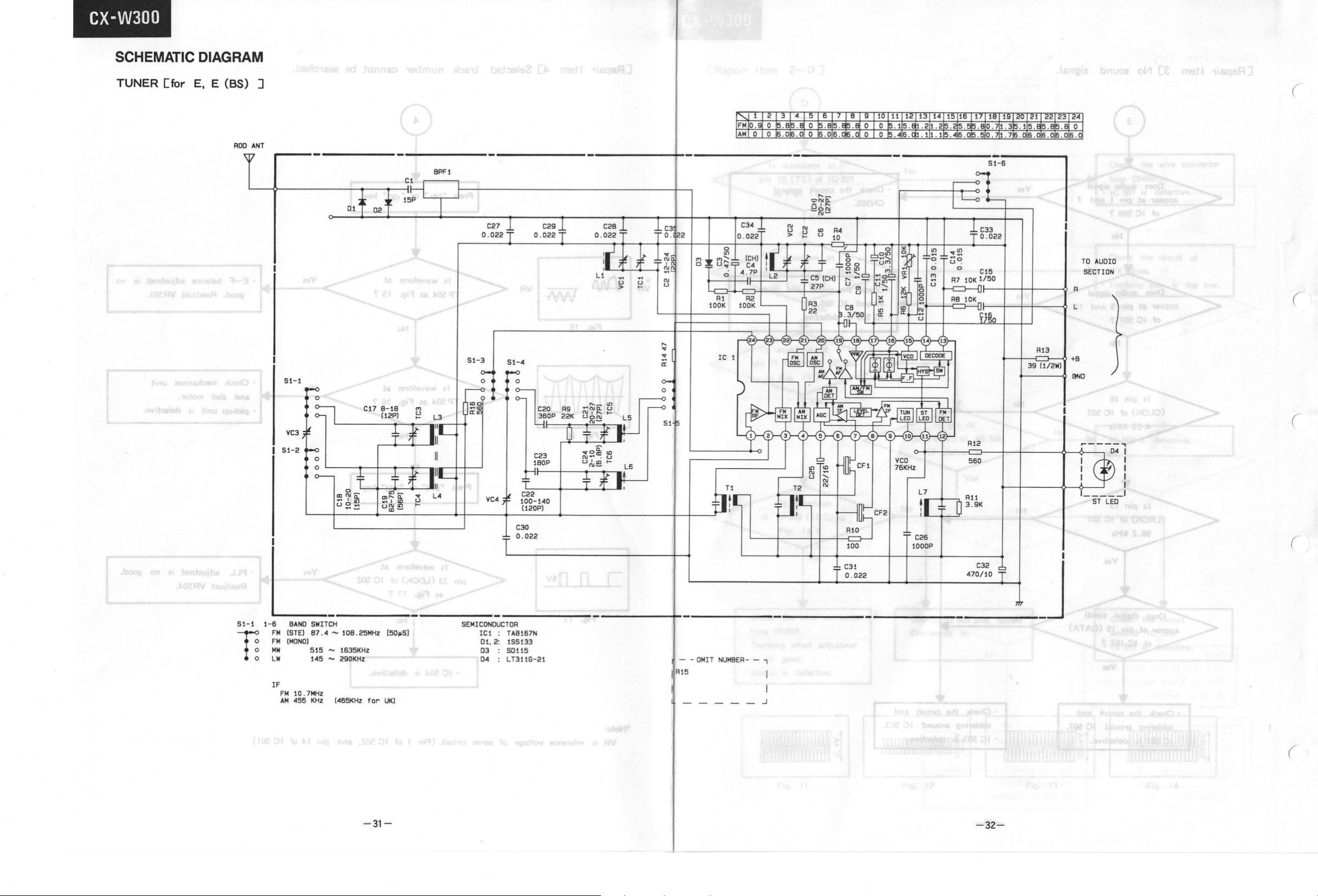
TUNER
TUNER
I
SPECIFICATIONS
REPLACEMENT
POINTER
POINT
ALIGNMENT
ALIGNMENT
CD
PLAYER
2
INSTRUCTIONS
FOR
HANDLING
BLOCK
LOCATIONS
PICKUP
SETTING
SET UP 11
12
4
5
7
(TUNER)
AND
INCORPORATED-
HiGH PERFORMANCE
POINT
3
OPTICAL
10
PARTS
ARE
SUBJECT
PORTABLE
CIRCUIT
TROUBLESHOOTING
SCHEMATIC
PCB
VIEWS
WIRING
EXPLODED
ELECTRICAL
TO
CREATIVE
LOCATIONS
ADJUSTMENT
DIAGRAM
43
DIAGRAM
VIEW
PARTS
CHANGE
53
57
FOR IMPROVEMENT.
SOUND
(CD) 18
20
CHARTS
31
LIST
22
65
SYSTEM
TEST
November 1991 YOKOHAMA WORKS
Page 2

CX-W300
1
SAFETY
The following precautions should be observed when servicing.
1.
Since many parts in the unit have special safety-related characteristics, always use genuine Hitachi's
2. Before returning a repaired unit to the customer, the service technician must thoroughly test the unit to
PRECAUTIONS
replacement parts. Especially critical parts in the power circuit block should not be replaced with other
makers.
ascertain that it is completely safe to operate without danger of electrical shock.
Critical parts are marked with A in the circuit diagram and printed wiring board.
1;^
SPECIFICATIONS
GENERAL
Power
Supply:
Power
Consumption:
Power
Output:
Speakers:
Dimensions:
Weight:
.
RADIO
Circuit
System: FM/MW/LW-3bands
Tuning
Range:
SECTION
SECTION
AC: 120V, 60 Hz [for UC]
AC: 230V, 50 Hz [for E]
AC: 240V, 50 Hz [for E(BS)]
AC: 110-120V/220-240V, 50/60 Hz
[for
DC: 9V ["D" CELL (lEC R20) .--^
16 W
20 W P.M.P. (AC operation)
3
10 cm X 2
3
550 (W) X 185 (H) X 196 (D) mm
4.5 kg (with batteries)
superheterodyne [for E, E(BS)]
FM/SW/MW-3bands
superheterodyne
[for
FM/MW-2bands
superheterodyne [for UC]
FM:
FM:
SW: 3.9 to 12 MHz [for E, E(BS)]
MW:
MW:
W, W(UN), W(AU)]
SUM1
X 6 or equlpment]
W X 2 (10% T.H.D. DC operation)
n
W, W(UN),W(AU)]
87.5 to 108.5 MHz [except UC]
88 to 108 MHz [for UC]
520 to 1,620 kHz [except UC]
520 to 1,740 kHz [for UC]
LW: 148 to 287 kHz [for E, E(BS)]
Intermediate
Frequency:
Antennas:
(Aerials)
TAPE
Tape:
Tracl<
Tape
Recording
Erasing
Frequency
Output:
Load
.
CD
Playing
Diameter:
Sampling
Quantization
Frequency
Specifications are subject to change without notice for
performance improvement.
RECORDER
System:
Speed:
System:
System:
Response:
Impedance:
PLAYER
Time:
Frequency:
Number:
Response:
FM:
10.7 MHz
MW/LW: 465 kHz [for E(BS)]
SW/MW/LW: 455 kHz
FM/SW/SW2: Rod antenna
SW/MW/LW; Built in ferrite
[except E(BS)]
antenna
SECTION
Cassette tape
4 tracks 2 channels stereo
4.75 cm/sec.
AC bias 70 kHz
Magnet
Normal: 70 to 10,000 Hz
CD out: 0.5V
Headphones: 8 to 100 Q
Speaker : 3 fi
1
ka
SECTION
Approx. 60 minutes/one side
120 mm/80 mm
44.1
kHz
16 bit linear/channel
20 to 20,000 Hz
The
caution
labels
O
on laser
•
NEVER
•
NE JAMAIS TOUCHER L'OBJECTIF.
•
DIE
•
NO TOQUE
usage.
TOUCH
LINSE
Cfor
E, E (BS) . W, W (UN) , W (AU) ,]
THE LENS.
NIEMALS
NUNCA
BERÜHRENI.
LA LENTE.
1
(T—^——Tl
™
0
CsiS-^-^ _ ^
SU T3e
Cfor
E, E (BS) , W, W (UN) , W (AU) ,3
CLASS1
LASER
PRODUCT
mWLISERIItDIHIMI
FlllEOOROEFEHED. m
mam
m»
ET
gUE
EVIIEII
mmi mm
IE
«EffiOUUUE
lEtPOSITIM
tfor
OUVERI
COmOIJIIIE.
IMIECIE
UC]
u
ESI
Mne
IKFECIUEUI
011
ESI
IE
«im
3
«1
Page 3

CX-W300
DISASSEMBLY
1.
Open the cassette covers and take out the
cassette
2.
Remove the
3. Remove eight screws @ holding the rear
cabinet. ' ^
8. Remove four screws @ holding the
main PCB.
9. Remove the volume control panel.
10. Remove one screw (§) holding the
select
tapes.
switch arm.
INSTRUCTIONS
battery
cover and batteries.
Figure 1 ^Q^D
^
^^''Y8 J
1zyxwvutsrqponmlkjihgfedcbaZYXWVUTSRQPONMLKJIHGFEDCBA
i9ob Bnifitob (c>
4. Remove two screws (ë) and two screws
(§) holding the CD mechanism kit.
5. Remove two screws (§) holding the CD
PCB.
6. Remove four screws (E) holding the CD
mechanism.
7. Remove two screws (F) holding the tuner
chassis.
Figure 2
11.
Remove six screws Q) holding the
cassette
mechanism.
Figure 3
Checl<
that
exposed parts are acceptably insulated
from
the supply circuit before returning the
instrument repaired to the customer.
Checking
Power (Operate) switch is set to ON.
Next,
measure the resistance value between the
both
poles of attachment cup (Power supply plug)
and the CD OUT terminal of rear plate and check
that
the resistance value is 500 kohms or more.
method
Figure 4
Insulation tester (DC
(Exposed
500V)
part)
qu) ISDiJtsV (E
Page 4

CX-W300
INSTRUCTION FOR HANDLING OPTICAL SYSTEM BLOCK PICKUP
Electrostatic breakdown of the laser diode in the optical system block may occur due to a potential 5;
difference caused by electrostatic charge accumulated on clothing, human body, etc. g
A ground must be provided as follows to prevent any electrostatic charge during unpacking or repair
work. ;
1.
Ground for Human Body ^^'^'^^ ' ^ - ^ " ® '
Be sure to wear a grounding band ( 1 Mohm) that is properly grounded to remove any static
electricity that may be charged on the body.
2. Ground for Work bench : , . ^
Be sure to place a conductive sheet ( 1 Mohm) or copper plate with proper grounding on the work
bench or other surface on which the pickup is to be placed.
3.
Because the static electricity charge on the clothing does not discharge through the body grounding '
band,
do not let clothing contact the pickup unit.
i INCORRECT
Figure 5
Note:
Laser diodes are so susceptible to
damage from static electricity that even if
a static discharge does not ruin the diode,
it can shorten its life or cause it to work
improperly.
"<3)
0 Grounding band
1Mn
CORRECT
^.
.Rins (ioiiwi f:mk.'
Conductive Sheet
or Copper Plate
Figure 6
PRECAUTIONS FOR CHECKING BEAM EMISSION OF LASER DIODE
V.!*
ovanafl .8
The laser beam of this unit is focused on the reflecting surface of the objective lens in the optical 1
system block. Therefore, keep your eyes at least 12 inches (30 cm) away from the objective lens when ^ j
the laser diode is ON. |., ^
llOperation Check Method for Laser Diode and Focus Search FunctionH i
When the POWER switch is turned ON after the chucking arm is removed, observe the objective lens
and confirm that the following operations are performed properly. i
(The optical system block should be at the lead-in area position when it is checked at this time.) -.
(1) The laser should be at the innermost position after the chucking arm is removed. ;1
(2) This diffused light of the laser beam can be seen when the POWER switch is turned ON. ï ritoJ |;
(3) Vertical (up and down) movement of the objective lens (2 or 3 times) will take place. '-'^
j-iinnii
mon j
Page 5

CX-W300
PICKUP
REPLACEMENT
Caution:
Laser
diodes are extremely susoeptibie to damage
static
electricity.
Even
if a static discharge does not ruin the diode, \
it can shorten its
life
or
cause
it to work improperly.
When replacing the pickup, use a oonductive mat, a
grounded soldering iron, and so on, to protect the laser
diode
from
static damage.
1.
Remove the CD mechanism assemdy by
referring to disassembly instructions.
from
IIU(
'io, 9iit tuo 9>teT .d
HfiftezyxwvutsrqponmlkjihgfedcbaZYXWVUTSRQPONMLKJIHGFEDCBA
iuo
Ground Conductive
Wrist
Band
for
Body
in
2.
Remove two sorews @ holding the CD
PCB.
(See Figure 8.)
3.
Remove four sorews (§) holding the CD
mechanism.
4.
Remove washer (D) holding the gear and
(See Figure 8.) _ .\
remove the gear. (See Figure 9.)
5. Remove two sorews (E) . (see Figure 9.)
,rroï
Figure 9
-.tqsiR
.Cf
Page 6

CX-W300
6.
Take out the pick-up (T). Then pull
out the shaft @. (See Figure 10.)
'feesf
^boib
ertt T>
er)* Jaej
Figure 10
oiJstE
(9
^0 « n9v3
ja
bsöriuoig
2 mo^^
aboib
7.
Place shorting round as shown in Figure 11
and remove both wire connectors.
8.
Unpack new pick-up.
lli
9.
After you connect the wire connectors,
desolder and remove the shorting tab.
(See
Figure 12.)
10.
Replace shaft and pick-up.
11.
Replace two screws .
12.
Replace gear and washer (B) .
bns
White
Red
Figure 12
Short
Short
Round
Round
13.
Replace four screws (g) holding the CD
mechanism.
14.
Replace two screws (K) holding the CD
PDB.
15.
Replace the CD mechanism chassis.
-6-
{.e
s
Page 7

c
DIAL POINTER SETTING
i... ... ., -
1.
Remove the tuner
Turn the PVC gear counterclockwise.
2.
3.
Turn the tuning knob and slide the pointer to the check position on the tuner
4. Replace the tuner
dtiW
.3811 ^ 1-, ,
chassis.
chassis.
Tuning Knob
• •d bluoriz ti ,^i6q9lzyxwvutsrqponmlkjihgfedcbaZYXWVUTSRQPONMLKJIHGFEDCBA '\o soiv
sni
166I '
,>iv.v>J
bfxiT
31 io ,
Check
CX-W300
chassis.
Position
8-
-7-
Page 8

CX-W300
Whenever a unit is brought in for service or repair, it shouid be cleaned and lubricated and the
head shouid be demagnetized.
1.
Cleaning: Clean the head and all tape handling surfaces using Standard cleaner and cotton swabs.
Wipe dry.
2. Demagnetization: Do not use magnetized tools near the
normal use, the head will retain small amounts of residual magnetism which results in increased
noise and loss of high-frequency response. Use a Standard tape head demagnetizer to demagnetize
the playback
3.
Lubrication: Use a high-grade of specially formulated lubricant in the appropriate places.
Lubrication is normally required only when parts tend to
Use all lubricants sparingly and avoid contact with other parts.
head.
1
f;;;;^^:
head,
bind,
lUOO
1
since they can magnetize it. With
or after long periods of use.
.S
Pre-Adjustment Procedures * s ^^-^ ^
1.
Be sure to demagnetize and clean the head before proceeding with head adjustment.
2. Never use a magnetized screwdriver for the head adjustment.
Tape Speed (Figure 14)
1.
Remove the front cabinet.
2. Connect a frequency counter to the headphone jack parallel with a 32 ohm non-reactive dummy
load.zyxwvutsrqponmlkjihgfedcbaZYXWVUTSRQPONMLKJIHGFEDCBA
^•
3.
Adjust the pot, resistor in the motor to make the counter reading 3015 Hz while playing back
3000 Hz test tape.
-v-'^^-'VN//-/-
To Adjust
/-i-i'
Screwdriver
Adjust Holl
(.^- - '.-. v
Figure 14
Motor
-8-
Page 9

CX-W300
:^*AHTS..5T
Playback
1. Connect an SSVM or
2.
3.
1..
readjust to make the both
4. After adjustment,
Record/Playback
1.
2.
3.
4. After adjustment,
Head Azimuth Adjustment
Playback an 8 kHz test tape and turn the azimuth adjustment
output level of the
When the output level of the
left
secure
Head Azimuth Adjustment
Connect an SSVM or
Playback an 8 kHz test tape and turn the azimuth adjustment
output level of the
When the output level of the
at the same level.
left
secure
{R3HUT) a^OiTAOOJ
oscilloscope
and right
left
channels,
the
screw
oscilloscope
and right
left
the
screw
(Cassette
to
each
channels,
and right
and both directions at the same level. !
with lock paint or glue.
to
each
channels.
and right
with lock paint or glue.
1) (Figure 15)
of the headphones jack (dummy load 32 ohm) .
in the forward and reverse play modes.
channels,
(Cassette
of the headphone jack (dummy load 32 ohm) .
channels
and forward and reverse position differs, zyxwvutsrqponmlkjihgfedcbaZYXWVUTSRQPONMLKJIHGFEDCBA
2) (Figure 15)
differs,readjust to make the both
screw
to obtain the maximum
screw
to obtain the maximum
channels
or -9-
Page 10

CX-W300
TEST
Cfor
POINT LOCATIONS (TUNER)
E, E (BS) , W, W (UM) , W (AU) 3
-10-
Page 11

CX-W300
TUNER
ALIGNMENT
'\J U_ •
Ssope
-O
SET
Loop Antenna
,«.M
V H O-
UP
Tkl3MH0üA
SSVM
Dummy
Load
Set
I
TP3
-O TP2
32 ohm
O-
JL Ceramic
TfT
I
I
J
L
"o.OluF
I
Figure
FM
IF
Sweep Generator
Scope
signal
—O H Out
-O V
-OGND GNDO-
O—
InO-
Figure
(8i
bnt
Headphone
18
Ceramic
0.022uF
H(
19
Scope
FI3VIUT
MA
39*8
cjsiB
FM Signal Generator
FM
Dummy
inzyxwvutsrqponmlkjihgfedcbaZYXWVUTSRQPONMLKJIHGFEDCBA
O
FM SG.
^
Set
to
TP2 L
FM
Dummy
'-i
Set
I
^I
Figure
1^
)T
R1=Z0
R2=75
Headphone
Jack
^_J{L^
Dummy
Figure
20
(8f
bnfe
ZO =
Output
ohm-zo/
impedance
2
Sgüfc'i
21 ,vpc
SSVM
SSVM
Load
32 ohm
8.? syiuytï) inamngilA "?>1 '.VJ
of FM
Counter
Scope
I
I
SG.
- - ^
g.linuT
pniAOBil
' i
t !
ili
i r f
TP5
TP2
O O-
Dummy
-11-
Het
330k
ohm
Figure
Load
22
I
I
J
L
Page 12

CX-W300
TUNER
Cfor
AM IF
Step
MW RF
Step
ALIGNMENT
E, E (BS) :
Alignment (Figures
Alignment
IF
Calibration
Alignment (Figures
Alignment
16 and 18)
Frequency
of Signal
Generator
1000
kHz
16 and 18)
Frequency
of Signal
Generator
Tuning
Dial
Setting
1000
kHz
Tuning
Dial
Setting
I
I
Adjustment
li
T2 Obtain sine-wave
maximum amplitude.
Max.
(
11
O—I
1
vo
O—j—I
; O H V
Adjustment
l!,.n..H MA
Remark
Remarks
s
and
LW
Step
Tuning Range
Calibration
Adjustment
Tracking
RF
Alignment (Figures
Alignment
Tuning Range
Calibration
Adjustment
Tracking
of
of
kHz
515
1635
kHz
600
kHz
1400
kHz
Repeat
the
16 and 18)
Frequency
of Signal
Generator
kHz
145
290
kHz
150
kHz
kHz
280
Low
end
High
end
600
kHz
1400
kHz
above adjustments.
Tuning
Dial
Setting
Low
end
High
end
150
kHz
280
kHz
L
5
TC
5
L
3
TC
3
Adjustment
L6
TC
6
L
4
TC
4
Obtain sine-wave
maximum amplitude.
Max.
Remarks
Obtain sine-wave
maximum amplitude.
Max.
and
and
Repeat
the
above adjustments.
-12-
Page 13

FM IF Alignment (Figures 16 and 19)
Frequency
Frequency
Step
Step
Alignment
Alignment
of Signal
of Signal
Generator
Generator Setting
Tuning
Dial
Adjustment
Adjustment
Rpmarlo:
CX-W300
JA
H3HUT
1 IF
Calibration
10.7 MHz
Low
End Turn L 7
2
1
r
1
i
3
1
u
80TzyxwvutsrqponmlkjihgfedcbaZYXWVUTSRQPONMLKJIHGFEDCBA V' hna
FM RF Alignment (Figures 16, 20 and 21)
Tuning
Dial
Setting
Step
Alignment
Frequency
of Signal
Generator
rlgiH
fully
counter
clockwise.
T 1
L
7 Obtain S curve and
Adjustment
Obtain symetrical curve
and maximum amplitude.
Max.
10.7 MHz
maximum amplitude.
1
Max.
10.7MH2
I 5 zyxwvutsrqponmlkjihgfedcbaZYXWVUTSRQPONMLKJIHGFEDCBA
i
c
Remarks
Tuning Range
Calibration
Adjustment of
Tracking
I
Low
87.35 MHz
108.25
MHz
90 MHz
end
High
end
90 MHz
106 MHz 106 MHz
Repeat the above adjustments.
Ü
-1
-13-
L
2 Obtain sine-wave and
maximum amplitude.
TC 2
L
1
TC1
sHM
Max.
^>lt.A..I»-i
01
•> I
i \
'
S
Page 14

CX-W300
TUNER
Cfor
ALIGNMENT
W, W (UN) , W (AU)zyxwvutsrqponmlkjihgfedcbaZYXWVUTSRQPONMLKJIHGFEDCBA 1
AM IF Alignment (Figures 16 and 18)
Frequency
Step
Alignment
IF
Calibration
bf.
of Signal
Generator
1000 kHz
MW RF Alignment (Figures 16 and 18)
Frequency
Step
Alignment
of Signal
Generator
Tuning
Dial
Setting
1000 kHz
! r
j
Tuning
Dial
Setting
(er
zyxwvutsrqponmlkjihgfedcbaZYXWVUTSRQPONMLKJIHGFEDCBA bns 8f eeiuei"^* tnemneilA M'^^
Adjustment
T 2
Obtain sine-wave and
maximum amplitude.
Remarks
r
T
Max.
Adjustment
' Remarks
Tuning Range
Tuning Range
1
Calibration
Calibration
2
3
Adjustment of
Adjustment of
Adjustment of
Track
ing
Track
ing
Track
ing
4
5
SW
RF Alignment (Figures 16 and 18)
Step
Alignment
Tuning Range
Calibration
Adjustment of
Tracking
515 kHz
1635 kHz
600 kHz
600 kHz
1400 kHz 1400 kHz
Repeat the above adjustments.
SOT
Frequency
of Signal
Generator
3.8 MHz
12.3 MHz
5
MHz
10 MHz
Low
end
High
end
600 kHz
600 kHz
bi»
HpiH
^HM Oe 1 sHM OP
Tuning
Dial
Setting
Low
end
High
end
5
MHz
10 MHz
L
TC
L
L
TC
1
Adjustment
L
TC
L
TC
5 Obtain sine-wave and
5
3
3
3
Obtain sine-wave and
maximum amplitude.
maximum amplitude.
Max.
Max.
'UU
1
Remarks
6
6
4
4
Obtain sine-wave and
maximum amplitude.
Max.
Repeat the above adjustments.
-14-
Page 15

CX-W300
FM IF Alignment (Figures 16 and 19)
Frequency
Step
Alignment
IF
Calibration
of Signal
Generator
10.7 MHz
Low
(8t bne Tf
Tuning
Dial
Setting
End Turn L 7
!
Adjustment
fully
counter
clockwise.
Remarks
T 1
Obtain symetrical curve
and maximum amplitude.
r
Max.
10.7 MHz
L
7 Obtain S curve and
maximum amplitude.
Max.
10.7 MHz
^! MA
q9T>-
V
, li li 'I . i
FM RF Alignment (Figures 16, 20 and 21)
Frequency
Step
Tuning Range
Calibration
Adjustment of
Tracking
Alignment
of Signal
Generator
108.25
Repeat the above adjustments.
l
•
i £0T
Tuning
Dial
Setting
Low
87.35
MHz
MHz
90 MHz 90 MHz
106 MHz
end
High
end
106 MHz
Adjustment
L
2
TC
2
L
1
TC1
Remarks
Obtain sine-wave and
maximum amplitude.
Max.
Page 16

CX-W300
TUNER
Efor H, HC:
AM IF Alignment (Figures 17 and 18)
Step Alignment
MW RF Alignment (Figures 17 and 18)
Step
ALIGNMENT
IF Calibration
Alignment
Tuning Range
Calibration
Frequency
of Signal
Generator
1000 kHz
.tdO I
-.me i
Frequency
of Signal
Generator
515 kHz
1750 kHz
r
T
Tuning
Dial
Setting
1000 kHz
Tuning
Dial
Setting
Low end L 4
High end
Adjustment
T2
Adjustment
TC 4
Remarks
Obtain sine-wave and
maximum amplitude.
I
Max .
Obtain sine-wave and
maximum amplitude.
4\
Remarks
Adjustment of
Tracking
FM IF Alignment (Figures 17 and 19)
Step Alignment
IF Calibration
600 kHz 600 kHz L 3
1400 kHz 1400 kHz TC 3
Repeat the above adjustments.
Frequency
of Signal
Generator
10.7 MHz Low End
Tuning
Dial
Setting
Adjustment
Turn L 5
fully counter
clockwise.
T 1
L 5
Max .
Remarks
.X;
0
Obtain symetrical curve
and maximum amplitude.
Max .
10.7MHz
Obtain S curve and
maximum amplitude.
-16-
Max .
V
10.7 MHz
Page 17

FM RF Alignment (Figures 16, 20 and 21)
(00) a^oiTAOOj THioq
CX-W300
zyxwvutsrqponmlkjihgfedcbaZYXWVUTSRQPONMLKJIHGFEDCBA
TBST
Frequency
Step
1
2
3
4
5
Cfor
E, E (BS) , W, W (UN) , W (AU) , H, HCl
Alignment
Tuning Range
Tuning Range
Calibration
Calibration
Adjustment of
Adjustment of
Tracking
Tracking
of Signal
Generator
87.5 MHz
108.5 MHz High end
90 MHz 90 MHz
106 MHz 106 MHz
Repeat the above adjustments.
Tuning
Dial
Setting
Low
end
FM Stereo Adjustment (Figures 16, 17 and 22)
Functin
Radio
Adjust
VR1 on the Tuner PCB for a frequency counter read 76 kHz.
Switch :RADIO position
Switch :FM
STEREO
position
Adjustment
L
2
TC 2
L
1
TC1
Remarks
Obtain sine-wave and
llletAIIIIUIM
Max.
Max.
dllIjJIIlUUB.
'UU'
1
Remarks:
1) When aligning FM IF, the symmetrical curve may not be obtained by setting the marker of the
sweep
generator (10.7 MHz) . This is due to the ceramic
the marker, align the curve as symmetrically as possible
2) When aligning the range and adjusting the tracking, proceed
FM—MW-LW:for
FM—MW
3) Use a screwdriver
Cfor H, HCl .
E, E (BS) 1 , FM—SW—MW Cfor W, W (UN) , W (AU) 1 ,
with
a plastic grip for all alignments.
filter
used in the unit. Regardless of
with
peak output.
with
alignment in a sequence of
-17-
Page 18

CX-W300
TEST
POINT LOCATIONS (CD)
Equipment Required
SSVM
Frequency Counter
Oscilloscope
A Regular Compact Disc
Test
Disc PHILIPS 5A
Test
Disc SONY
Dummy
load lOk ohm
YEDS-
18
S
Figure 23
-18-
Page 19

CX-W300
VTVM
P
O-
Oscilloscope
Ó
O-
I
(
Figure
I
I
Figure
24
25
'M3ÏV1T8ÜIQAzyxwvutsrqponmlkjihgfedcbaZYXWVUTSRQPONMLKJIHGFEDCBA
OS
bns ?S
.
,
g
g
O.zyxwvutsrqponmlkjihgfedcbaZYXWVUTSRQPONMLKJIHGFEDCBA
CL
TP504
TP502
J
•-•"'V+st-nlsui.DA cviag
Oscilloscope
O
o-
I
I
Figure
Frequency
Q
O-
Counter
Figure
TSüDf l I O
^uoo'=5
27
28
O T O
in
in O
Q.
Q.
Short
Oscilloscope
0
0
-
I - C!
/mzyxwvutsrqponmlkjihgfedcbaZYXWVUTSRQPONMLKJIHGFEDCBA {lOf VO —
1
l J
Figure
26
•
q-qVrn
00 fzyxwvutsrqponmlkjihgfedcbaZYXWVUTSRQPONMLKJIHGFEDCBA luoóe,
1
g g
1-
to -6(1312
r -.
Q1-
iO-!i9
ittHlüli
euDol
^^iw>lc)ob
-lalnuco
gO?f''('
m u nifcr- euoo! srft
s>26»ioni
oT
-19-
Page 20

CX-W300
CIRCUIT
Focus
Step Connect
See
Figure
ADJUSTMENT
Servo
Adjustmet
Focus
24
0
(Figures 24, 25 and 26)
Setting
ff
set
Adjustmet
Play
the
*
regular
disc
Adjust i Remarks 1 !
VR502
the
Obtain
diamond windows
maxmum amplitude
of the eye
and the
pattern.
^sssmem amsiSkmmMmemm
i
The
above
The
diamond window
large
is on
and
clear.zyxwvutsrqponmlkjihgfedcbaZYXWVUTSRQPONMLKJIHGFEDCBA
example
,zyxwvutsrqponmlkjihgfedcbaZYXWVUTSRQPONMLKJIHGFEDCBA . i_.
in the
of
good
eye
center portion
biggest
pattern.
are
EF
See
Figure
Gain
See
Figure
Balance
25
Setting
26
Adjustment
Play
the
regular
Push
the "|>|> " key
Play
the
regular
disc
disc
VR501
VR505
Focus
error signal
EF
balance signal
of
about
100
-ov
A=B
-ov
mVp-p
100
mV P-P
2
To
increase
the
focus gain,
turn
VR505 counter clockwise
-20-
Page 21

CX-W300
Tracking
Step
Servo Adjustment (Figures 27 and 28)
connect
Gain
See
Figure
Se
27
tting
Play
YEDS-
Setting
the regular
7
disc
Adjust
VR503
aTRAHO
OMITOOH83Jaüi
~1
Remarks
I
lllll
Obtain the tracking drive signal of about
500 mVp-p.
-OV 500mV P-P
r
L
Change
and confirm no skipping.
If there is any skipping, adjust VR503 to reduce the tracking servo gain
occurs.
See
Figure
Discon
the
disc
to PHILIPS Test
Toreduce the gain,
PLL
(Phase Locked Loop) Adjustment
Slide
the power switch
28
neet TP 510 and TP 511.
(See
Figure 28)
on
(without
Play
the regular
turn
disc)
disc
VR503 counter clockwise.
Disc
5A and play where the black dot of 600 /um is,
VR504
counter
Check
±0.005 MHz.
reading to be 4.32 MHz. +30 kHz
counter reading
4.3218
till
no skipping
-10 kHz
MHz
-21-
Page 22

CX-W300
TRO U BL ESHO O T ING
CHART S
Open
CD
door
and function
switch to CD position.
Load CD and Close CD
1
• t-
—•
O
Yes
door.
Press
"PLAY/PAUSE" key.
or
•O
OK
-22
Page 23

CX-W3 00
CRepair Item 11 At
70ms
5V
'
Power
on
Fig.
1
power
on, "O" is not displayed. "N^
•
No ^
Yes
Yes
i
i
i
No ^
No ^
No ^
IC
509
is
detective.
• Q 504
is
• Q 504
•
Or,
•
Or,
it.
it.
•
•
Ceramic resonator
Ceramic resonator
is
is
•
IC
•
IC
•
Or,
•
Or,
it.
it.
detective.
is
detective.
check
the
check
the
detective.
detective.
503
is
detective.
503
is
detective.
check
the
check
the
circuit around
circuit around
CF
501
CF
501
circuit around
circuit around
.tos 0 1 loi e
.svitc»V.>b
CRepair ItemzyxwvutsrqponmlkjihgfedcbaZYXWVUTSRQPONMLKJIHGFEDCBA 21 " " is displayed instead of total track
IC
504
is
detective.
Or,
check
the
it.
loose soldering
circuit around
etc.
0
Check
how
much time
until
" " is
atter
CD
door
has
ti
About
:
5 sec.
About
10 sec.
bnuoie -zyxwvutsrqponmlkjihgfedcbaZYXWVUTSRQPONMLKJIHGFEDCBA
8*
niq bnazyxwvutsrqponmlkjihgfedcbaZYXWVUTSRQPONMLKJIHGFEDCBA i' é
it
displayed
closed.
takes
number
J 1.
f
after "O" is displayed.
;" 1
I
<
11
About
15 sec.
1
0
0
-23-
13
nrtl AD3 r\ 0
.soe C!
SOS
O'
©
Page 24

CX-W300
CRepair
Item
2—A D
Load a disc
And check the following.
and close CD door.
NOTE : If an optical power meteris not available,
watch radiation through the lens of pickup
unit
with
distance more than 30 cm
pickup unit.
from
Fig.
Fig.
2
5
Check
Wire
connector
Soldering for IC 501.
IC
501 is detective.
jfezyxwvutsrqponmlkjihgfedcbaZYXWVUTSRQPONMLKJIHGFEDCBA
Qn\^bkj?. 920-
No ^
No ^
No ^ No ^
No
No
1
Yes
pickup is detective.
• Check
• Check
Soldering at pin 15, 16 and
Soldering at pin 15, 16 and
28 of IC 501.
28 of IC 501.
• IC 501 is detective.
• IC 501 is detective.
• IC 501 is detective. • IC 501 is detective.
• Check the circuit
pin 19 of IC 501
of IC 502.
of IC 502.
•
Focus
servo gain
•
Focus
servo gain
readjust VR505.
readjust VR505.
from
CN500
around
and pin 48
Is
too low,
• Check the circuit around
IC
502.
• IC 502 is detective.
-24-
Cv
Page 25

CX-W 300
CRepair
CRepair
Item
2—A 13
Check
Circuit around Q501.
Wire
connector
Q 501 is defective.
• Pickup is defective.
Item
2—AzyxwvutsrqponmlkjihgfedcbaZYXWVUTSRQPONMLKJIHGFEDCBA 23 Object lens of pickup
LASER
from
CN501.
does not
emit
unit
does not move up and
i
• Check
Wire
connector
from
CN501.
• Pickup is
Yes
f
defective.
!
t
• Check
around
• IC 506
Yes
the circuit
IC
502.
is
defective.
-25-
88.2kHz
Does
appear at pin 40 (WDCK)
"""'^^•^of IC 502
• Check the
around IC 506 soldering
etc.
• IC 502 or IC 504 is
defective..
clock pulse^
?^^'^^''^
Yes
circuit
^
No
!
!
\
»
• Check the circuit
around CF 501, IC 503.
• IC 503 is defective.
i-wHO
i-wHO
•
•
1
Page 26

CX- W3 0 0
CRepair Item
2—B H
Yes
Yes
Check mechanically
Clamper
Turn
table unit
etc.
.9 viJo9Ï5 )b
2i
qu)f.ii^
•
Check
Wire
connector
TrOM I
OINOUt .
•
Spindle
is
detective.
•
motor
Check
EFM and
ASY
lines.
IC 503
is
detective.
.• jvi}oe1ob ?t 6 C? O'
Yes
i
f
•
Check soldering
for
IC 503
•
IC
503
is
detective.
•
IC 503
is
detective. IC 505
t
2.5V
Yes
is
i f
•
Check
Soldering
IC
502.
•
IC
502
detective.
loSctsnnöo
.tOcHO
for
is
detective.
siiW
mot'
Fig.
8
- 26-
Fig.
9
Page 27

CX-W300
CRepair
Item
2-C D '
Watch
the
waveform
at
TP
501 (RFO)
an
oscilloscope.
with
Check
"
ASY "
and
IC
IC
501
the
L
O-
soldering concerned
lines
for IC 501
503.
or IC 503 is
detective.
r
'
• Check
Pins
23,
Pins
5,
•
IC 504 is
Yes
^.. I-li"
Ol
bntio
<
24
and 25 of IC
8
and 64 of IC 504.
defective.
.
503.
Yes
w
•
IC 501 is
•
IC 501 is
Check
around
IC
Check
around
IC
defective.
defective.
CF 501
503 is
the
IC 503.
503 is
'r-*-*4,*'.'^ i'^t.'-vzyxwvutsrqponmlkjihgfedcbaZYXWVUTSRQPONMLKJIHGFEDCBA
and the
it.
defective.
circuit
defective.
circuit
and
soldering
t^iii^v - '
Fig.
10
• Check
the
circuit
around
IC 502.
• PLL adjustment
Readjust
IC 502 is
•
VR504.
defective.
and
is no
-27-
soldering
good.
J
y
Page 28

CX-W300
CRepair Item
2—DU
No
No
No
No
(ni o?9vEW
fMrw ( O te
Sri'
rinJsW
—W
w
C O-s mati
• Check the wire connector
from
from
CN501.
CN501.
• IC 501 is defective.
• Check the circuit of
•TE"
lines.
•TE"
lines.
• Tracking gain is too low.
• Tracking gain is too low.
riaoaFi:
'1
Check the wire connector
from
CN501.
Tracking offset adjustmet
is no good.
pickup is defective.
Fig.
11
Check IC 505 and circuit
Concerned it.
Fig.
12
-28-
Fig.
13
Check the circuit
around IC 501.
IC 501 is defective.
Fig.
14
Page 29

Page 30
Page 31

Page 32

Page 33

Page 34

Page 35

Page 36

Page 37

Page 38

Page 39

Page 40

Page 41

Page 42

Page 43

Page 44

Page 45

Page 46

Page 47

EX PLO DE D
FRONT CABINET
VIEW
Page 48

-64-
Page 49

CX-W300
ELECTRICAL
^
PRODUCT
w Before replacing
Manual.
ABBREVIATI0h4S:
SYMBOL
No.
C
1
02
03
C4
05
06
07
08
09
0 10
011
0 12
0 13
014
0 15
0 16
0 17
0 18
0 19
O20
0 21
0 22
SAFETY
Dont degrade the
PART
9301-151-5-04
9301-152-2-04
9301-151-8-04
0937-854-7-96
9300-254-7-85
0930-242-7-04
0930-242-7-04
0930-242-4-04
9301-451-0-25
9301-456-8-15
0937-853-3-86
0937-850-1-06
0937-853-3-86
0937-850-1-06
9335-451-0-24
0938-631-5-35
9302-332-2-39
0938-631-5-35
9302-332-2-39
0936-350-1-06
0936-350-1-06
9301-151-2-04
9301-152-2-85
9301-151-5-04
9301-153-3-85
9301-155-6-04
9301-151-0-04
9302-332-2-39
0930-453-6-14
9302-332-2-39
9301-152-4-04
0937-822-2-06
9301-451-2-15
9302-332-2-39
PARTS
NOTE:
any of
No.
CAPACITORS
LIST
Components
these components, read carefully,
safety
of the
Semiconductor
DESORIPTION
CC
15PF ±5%
00
22PF
Cfor
±5% 50V
E,E (BS) ,W,W (UN)
CO
18PF ±5% 50V
Cfor
H, HOD
EL
0.47uF ±20% 50V
00
4.7PF
CD
CD
:for E,E (BS) ,W,W (UN)
CD
llfor
00
Cfor
CO
Cfor
EL
EL
EL
EL
MF
OD
Cfor
00 0.033uF -|-80%/-20%
Cfor
OD O.OISuF
Cfor
00 0.033uF
Cfor
EL
EL
00 12PF ±5% 50V
Cfor
CC
Cfor
CC
Cfor
00
Cfor
00
Cfor
00 10PF ±5%
Cfor
00 0.033uF
Cfor
ST
Cfor
00 0.033uF
Cfor
OO 24PF
Cfor
EL
Cfor
CC
Cfor
CC
Cfor
±10% 50V
27PF
±5% 50V
27PF
±5% 50V
24PF
±5% 50V
H, HC:
1000PF
±10% 50V
E,E (BS) ,W,W (UN)
680PF
±10% 50V
H, HO:
3.3uF ±20% 50V
luF ±20% 50V
3.3uF ±20%
luF ±20% 50V
1000PF
±5% 50V
0.015uF ±10% 25V
E,E (BS) ,W,W (UN) ,W (AU)3
H, HO:
±10%
E,E (BS) ,W,W (UN)
+80%/-20%
H,zyxwvutsrqponmlkjihgfedcbaZYXWVUTSRQPONMLKJIHGFEDCBA HCl
luF ±20% 50V
luF ±20% 50V
E,E (BS) ,W,W (UN)
2.2PF
±10%
H, HC3
15PF ±5% 50V
E, E (BS) :
3.3PF
±10%
H, HO]
56PF
±5% 50V
E, E (BS) 3
W, W (UN) , W (AU) 1
+80%/-20%
H, HCl
360PF
±5% 50V
E,E (BS) ,W,W (UN) ,W (AU):
+80%/-20%
H, H03
±5% 50V
E,E (BS) ,W,W (UN) ,W (AU):
22uF
±20% 16V
H, HC:
120PF
±10%
E, E (BS) 3
0.033uF
+80%/-20%
H, HO:
marked
receiver
...
CC:
...
CF:
...
...
Q:
,W (AU)3
,W (AU)3
,W (AU)3
,W (AU)3
,W (AU)3
with
through improper
Cylindrical ceramic,
EL:
Electrolytic,
Carbon
Transisstor,
50V
50V
50V
25V
50V
50V
50V
50V
50V
50V
50V
50V
!—
a^
have special characteristics
the
PRODUCT
ST:
film
D:
SYMBOL
No.
0 23
O
24
O
25
0 26
O
27
0 28
0 29
C30
0 31
0 32
O
33
034
0 35
0 36
to Not
0 100
0 101
0 102
0 103
0 104
O
105
0 106
O
107
0 108
0 109
C110
0 111
0 112
0113
C114
0115
0 116
0 117
0 118
0 119
0 120
0 121
servicing.
Diode,
SAFETY
CD:
Styrol
IC:
PART
No.
0930-451-8-14
0930-452-7-24
9301-451-0-25
9301-156-8-85
9301-151-5-04
0937-814-7-16
0937-822-2-06
9302-332-2-39
9301-451-0-25
9301-156-8-04
9302-332-2-39
9302-332-2-39
9302-332-2-39
9302-332-2-39
9302-332-2-39
0937-814-7-16
9302-332-2-39
9302-332-2-39
9302-332-2-39
Used
9336-756-8-14
9336-758-2-14
0931-251-0-25
0937-842-2-06
0938-631-8-35
0937-854-7-86
0937-854-7-86
0937-851-0-06
0937-850-1-06
0938-633-3-25
0937-850-1-06
0937-854-7-86
9301-451-0-25
0937-834-7-06
0937-854-7-96
0937-821-0-16
9335-451-0-45
9335-451-0-45
0937-721-0-26
0938-636-8-25
9301-456-8-15
Ceramic
IC
important
NOTICE
disc,
DESORIPTION
ST
180PF
Cfor
E, E (BS) :
ST
2700PF
Cfor
W, W (UN) , W (AU) 3
00
lOOOPF
Cfor
H, H03
CO
6.8PF
Cfor
E, E (BS) 3
00 15PF ±5%
Cfor
W, W (UN) , W (AU) 3
EL
470uF
H, HC3
Cfor
EL
22uF
Cfor
E,E (BS) ,W,W (UN) ,W (AU)3
CC
0.033uF
Cfor
H, H03
CC
1000PF
Cfor
E,E (BS) ,W,W (UN) ,W (AU)3
00
68PF
Cfor
H, H03
00 0.022uF
00 0.022uF
00 0.022uF
CC
0.022uF
Cfor
E,E (BS) ,W,W (UN) ,W (AU)3
00 0.022uF
Cfor
E,E (BS) ,W,W (UN) ,W (AU)3
EL
470uF
Cfor
E,E (BS) ,W,W (UN) .W (AU):
00 0.022uF
Cfor
E,E (BS) ,W,W (UN) ,W (AU):
00 0.022uF
Cfor
E,E (BS) ,W,W (UN) ,W (AU):
00 0.022uF
Cfor
E,E (BS) ,W,W (UN) ,W (AU):
MF
680PF
MF
820PF
OD 1000PF
EL
22uF
OD
0.018uF ±10% 25V
EL
4.7uF
EL
4.7uF
EL
lOuF
EL
luF ±20%
OD 3300PF
EL
luF ±20%
EL
4.7uF
00
lOOOPF
EL
47uF
EL
0.47uF ±20% 50V
EL
lOOuF
MF 0. luF ±10%
MF 0. luF ±10% 50V
EL
lOOOuF
CD
6800PF
OO 680PF
of
MF:
±5% 50V
±5% 50V
±10% 50V
±5%
±20%
±20%
+80%/-20%
±10%
±5%
+80%/-20%
+80%/-20%
+80%/-20%
+80%/-20%
+80%/-20%
±20%
+80%/-20%
+80%-20%
+80%/-20%
±5% 50V
±5% 50V
±10%
±20%
±20%
±20%
±20%
±10%
±20%
±10%
±20%
±20%
±20% 16V
±10%
±10% 50V
to
safety.
this Service
Mylar
film
50V
50V
lOV
16V
50V
50V
50V
25V
25V
25V
25V
25V
lOV
25V
25V
25V
t i j
50V
35V
50V
50V
50V
50V
25V
50V
50V
50V
25V
50V
25V
Mi n
16V
-65-
Page 50

CX-W300
SYMBOL
No.
C
122
0 123
C
124
C
125
to
C
129
C
130
C
131
C
132
C
133
to
C200
C201
C202
C203
C204
C205
C206
C207
C208
C209
C210
C211
C
212
C2I3
C214
0215
C
216
0217
0 218
0 219
C220
0 221
0 222
0 223
0 224
0 225
to
C229
O230
0 231
0 232
0 233
to
0 299
0 300
0 301
0 302
0 303
C
304
0 305
0 306
0 307
O308
C
309
C310
0 311
0 312
0 313
0 314
0 315
0 316
0 317
0 318
0 319
O320
0 321
0 322
0 323
0 324
C
325
0 326
0 327
PART
No.
9301-456-8-15
9301-152-2-04
9301-452-2-15
Used
Not
0937-851-0-96
0938-632-2-35
0937-851-0-96
Not
Used
9336-756-8-14
9336-756-8-14
0931-251-0-25
0937-842-2-06
0938-631-8-35
0937-854-7-86
0937-854-7-86
0937-851-0-06
0937-850-1-06
0938-633-3-25
0937-850-1-06
0937-854-7-86
9301-451-0-25
0937-834-7-06
0937-854-7-96
0937-821-0-16
9335-451-0-45
9335-451-0-45
0937-721-0-26
0938-636-8-25
9301-456-8-15
9301-456-8-15
9301-152-2-04
9301-452-2-15
Used
Not
0937-851-0-96
0938-632-2-35
0937-851-0-96
Not
Used
0937-722-2-26
0937-852-2-86
0937-711-0-26
0937-833-3-06
0937-842-2-06
0937-842-2-06
9336-751-8-15
9335-452-2-24
9302-021-0-35
0937-834-7-06
0938-634-7-25
0938-635-6-25
9302-021-0-35
9302-021-0-35
0937-834-7-06
0937-834-7-06
0937-851-0-06
0937-842-2-06
0937-814-7-16
0937-821-0-16
0937-854-7-86
0937-834-7-06
0937-722-2-26
0937-833-3-06
0937-821-0-16
9302-021-0-35
9302-021-0-35
9302-021-0-35
DESCRIPTION
00
680PF ±10%
00
22PF
00
220PF ±10%
EL
0. luF
00 0.022uF
EL
0. luF
MF 680
MF
680PF
CD
lOOOPF
EL
22uF ±20%
CD
O.OlSuF
EL
4.7uF
EL
4.7uF
EL
lOuF
EL
luF
CD
3300PF
EL
luF
EL
4.7uF
00
1000PF ±10%
EL
47uF
EL
0.47uF
EL
lOOuF ±20%
MF 0. luF
MF 0. luF
EL
lOOOuF ±20%
CD
6800
CO
680PF ±10%
CC
680PF
00
22PF ±5%
00
220PF
1
EL
0.1
uF
OD
0.022uF
EL
0.1
uF
EL
2200uF
EL
2.2uF
EL
lOOOuF ±20%
EL
33uF ±20%
EL
22uF ±20%
EL
22uF ±20%
MF
180PF
MF
2200PF ±5%
CC
O.OluF ±10%
EL
47uF ±20%
OD 4700PF ±10%
CD
5600PF ±10%
CC
O.OluF ±10%
00
O.OluF
EL
47uF ±20%
EL
47uF ±20%
EL
lOuF ±20%
EL
22uF ±20%
EL
470uF ±20%
EL
lOOuF ±20%
EL
4.7uF ±20%
EL
47uF
EL
2200uF
EL
33uF
EL
lOOuF ±20%
CC
O.OluF ±10%
CC
O.OluF ±10%
00
O.OluF ±10%
PF
PF
±5%
±20%
±10%
±20%
±5%
±5%
±10%
±10%
±20%
±20%
±20%
±20%
±10%
±20%
±20%
±20%
±20%
±10%
±10%
±10%
±10%
±10%
±20%
±10%
±20%
±20%
±20%
±10%
±10%
±20%
±20%
±20%
SYMBOL
No.
50V
50V
50V
50V
25V
50V
50V
50V
50V
35V
25V
50V
50V
50V
50V
25V
50V
50V
50V
25V
50V
16V
50V
50V
16V
25V
50V
50V
50V
50V
50V
25V
50V
16V
50V
lOV
25V
35V
35V
50V
50V
16V
25V
25V
25V
16V 0 548
16V
25V
25V
50V
35V to Not
lOV
16V
50V
25V
16V
25V
16V O606
16V
16V
16V
C328
0 329
0 330
0 331
to
C
339
C
340
C341
to
0 500
0 501
O502
0 503
O504
0 505
C506
C
507
C508
C509
0 510
0 511
0 512
0 513
0 514
C
515
0 516
0 517
to
C
519
C520
0 521
0 522
0 523
0 524
0 525
0 526
C
527
0 528
0 529
0 530
0 531
C
532
0 533
0 534
0 535
0 536
0 537
C
538
0 539
0 540
C
541
0 542
0 543
0 544
0 545
C
546
0 547
C549
C550
0 551
C552
C600
C601
O602
C603
O604
C605
C607
O608
0933-453-3-34
0933-451-0-44
0933-453-3-34
0937-854-7-86
0933-451-0-44
0937-812-2-06
0937-852-2-96
9302-021-0-35
9335-751-0-34
9302-354-7-39
0936-652-2-86
0937-812-2-06
0933-453-3-34
0937-854-7-96
0930-244-7-04
0930-244-7-04
0937-814-7-06
PART
No.
9302-021-0-35
0931-254-7-15
0937-814-7-16
Not
Used
0931-831-8-35
Not
Used
0937-850-1-06
0937-811-0-16
0337-851-0-06
9335-754-7-24
0930-245-6-04
0937-814-7-06
0937-814-7-06
0937-814-7-06
0933-453-3-34
9335-751-0-24
Used
Not
9335-754-7-24
9335-751-0-34
0937-854-7-96
9335-751-0-34
Used
Not
9302-351-0-49
9301-451-0-25
9302-351-0-49
9302-351-0-49
9301-152-2-04
9302-351-0-49
9302-354-7-39
0937-852-2-86
0937-852-2-96
0937-811-0-16
0937-814-7-16
0937-821-0-16
0937-821-0-16
Not
Used
0937-814-7-16
9301-451-0-25
Used
0937-811-0-16
0937-852-2-86
9335-758-2-24
0933-453-3-34
9335-751-0-24
0937-851-0-06
0933-453-3-34
9301-451-8-15
DESCRIPTION
O.OluF ±10%
CO
OD 470PF
EL
470uF ±20%
CD
O.OlSuF
EL
luF
lOOuF
EL
EL
lOuF
MF
4700PF ±5%
CD
56PF
EL
47uF ±20%
EL
47uF ±20% lOV
EL
47uF ±20% lOV
CF
0.033uF
MF
lOOOPF
MF
4700PF
OF
0.033uF
MF
O.OluF
0.47uF
EL
MF
O.OluF
CF
0.1
CF
0.033uF
EL
4.7uF
CF
0.1
EL
22uF ±20% lOV
EL
0.22uF
00
O.OluF
MF
O.OluF
0. luF
00
0.047uF
00
2.2uF
EL
EL
22uF ±20% lOV
CC
lOOOPF
OF
0.033uF
0.47uF
EL
CC
0.1
CC
0.1
22PF
00
00 47
00 47
47uF
EL
0.1
CO
CC
0.047uF + 80%/- 20%
EL
2.2uF
0.22uF
EL
lOOuF
EL
EL
470uF
EL
lOOuF
EL
lOOuF
470uF
EL
lOOOPF
00
EL
lOOuF
EL
2.2uF ±20%
MF
8200PF
OF
0.033uF
MF
lOOOPF
EL
lOuF
CF
0.033uF
CC
180PF ±10%
±10%
±10%
±20%
±20%
±20%
±5%
±5%
±5%
±5%
±5%
±5%
±20%
±5%
uF
±5%
±5%
±20%
uF
±5%
±20%
±10%
±5%
+
80%/-20%
+
80%/-20%
±20%
±10%
±5%
±20%
uF + 80%/- 20%
uF + 80%/- 20%
uF
±5%
±5%
±5%
±20% lOV
+
80%/- 20%
±20%
±20%
±20% lOV
±20%
±20%
±20%
±20% lOV
±10%
±20%
±5%
±5%
±5%
±20%
±5%
PF
PF
16V
50V
10V
25V
50V
10V
50V
50V
50V
10V
50V
50V
50V
50V
50V
50V
50V
J
r
0
r
0
50V
50V
50V
50V
50V
16V
50V
50V
50V
50V
50V
50V
50V
50V
50V
50V
50V
50V
50V
50V
50V
50V
lOV
16V
16V
50V
tov
50V
50V
50V
50V
50V
50V
50V
66-
Page 51

CX-W300
SYMBOL
No.
C609
to
C700
C701
C 702
C703
C704
C705
C706
C 707
C708
R
1
R2
R3
R4
R5
R6
R7
R8
R9
qzyxwvutsrqponmlkjihgfedcbaZYXWVUTSRQPONMLKJIHGFEDCBA,-i
R 10
R
11
R 12
R 13
R 14
R 15
R 16
R 17
to Not
R 100
R 101
R 102
R 103
R 104
R 105
R 106
R 107
R 108
R 109
R 110
R
111
R 112
R 113
R 114
R 115
R 116
R 117
R 118
R 119
R 120
R 121
R 122
R 123
R 124
to Not
R 129
R 130
R 131
R 132
R 133
R 134
R 135
R 136
PART
No.
Used
Not
0937-811-0-16
0937-852-2-86
9335-758-2-24
0933-453-3-34
9335-751-0-24
0937-851-0-06
0933-453-3-34
9301-451-8-15
0920-861-0-44
0920-861-0-44
0920-862-2-04
0920-861-0-04
0920-861-0-24
0920-861-2-34
0920-861-0-34
0920-861-0-34
0920-862-2-34
0920-863-3-34
0920-861-0-14
0920-863-9-24
0920-865-6-14
0920-023-9-04
0920-864-7-04
0920-863-9-24
0920-865-6-14
Used
0920-862-2-34
0920-861-0-34
0920-862-2-14
0920-862-2-44
0920-867-5-24
0920-862-2-34
0920-861-8-44
0920-861-8-44
0920-861-5-24
0920-863-3-44
0920-864-7-24
0920-865-6-34
0920-863-9-34
0920-863-9-34
0920-862-7-24
0920-861-8-34
0920-862-7-24
0920-863-9-44
0920-861-0-24
0920-862-2-24
0920-865-6-04
0920-862-7-34
0920-813-3-84
Used
0920-865-6-34
0920-863-3-34
0920-862-2-34
0920-863-9-44
0920-864-7-84
0920-862-2-24
0920-866-8-44
DESCRIPTION
lOOuF
EL
2.2uF
EL
MF
8200PF
CF
0.033uF
MF
1000PF
lOuF
EL
0.033uF
CF
180PF
CC
RESISTORS
CF
lOOk
CF
lOOk
CF 22
CF 10
CF
Ik
CF 12k
CF
lOk
CF
lOk
CF
22k
Cfor
CF 33k
:for
CF
100
CF
3.9k
CF
560
CF
39
CF
47
:for
E,E
CF 3.9k
W, W (UN) , W (AU) :
Cfor
CF 560
Cfor
E,E
CF
22k
CF
lOk
CF
220
CF
220k
CF
7.5k
CF 22k
CF
180k
CF
180k
CF
1.5k
CF
330k
CF 4.7k
CF 56k
CF
39k
CF
39k
CF
2.7k
CF 18k
CF
2.7k
CF
390k
CF
Ik
CF 2.2k
CF 56
CF
27k
CF 3. 3
CF
56k
CF
33k
CF
22k
CF
390k
CF 4.7
CF 2.2k
CF
680k
1
1
SRD
SRD 1 /
SRD 1/
SRD 1/
SRD 1 /
SRD 1 /
SRD 1/
SRD
SRD 1/
SRD 1/
SRD 1 /
SRD 1 /
SRD 1/
SRD 1 /
SRD 1 /
SRD 1/
SRD 1/
10V
50V
50V
50V
50V
50V
50V
50V
1/
1/
+
20%
±20%
±5%
±5%
±5%
+
20%
±5%
±10%
±5%
ohm
±5%
ohm
ohm
ohm
ohm
E,E
H, Hc:
ohm
ohm
±5%
±5%
±5%
±5%
ohm
ohm
±5%
±5%
ohm
ohm
±5%
(BS) ,W,W (UN) ,W (AU):
±5%
ohm
±5%
ohm
ohm
±5%
ohm
±5%
±5%
±5%
(BS) ,W,W (UN) ,W (AU):
ohm + 5%
ohm
±5%
(BS) ,W,W (UN) ,W (AU):
oü-o-8s<;-flioo i -
±5%
±5%
±5%
±5%
±5%
±5%
±5%
±5%
±5%
±5%
±5%
±5%
±5%
±5%
±5%
±5%
±5%
±5%
±5%
±5%
±5%
±5%
±5%
±5%
±5%
±5%
±5%
±5%
±5%
±5%
SRD 1/
SRD 1/
SRD 1/
SRD 1 /
SRD 1/
SRD 1/
SRD 1/
SRD 1/
SRD 1/
SRD 1/
SRD 1 /
SRD 1/
SRD 1/
SRD 1 /
SRD 1/
SRD 1/
SRD 1 /
SRD 1 /
SRD 1/
SRD 1/
SRD 1/
SRD 1 /
SRD 1/
SRD 1/
SRD 1/
SRD 1/
SRD 1 /
SRD 1 /
SRD 1 /
SRD 1/
ohm
ohm
ohm
ohm
ohm
ohm
ohm
ohm
ohm
ohm
ohm
ohm
ohm
ohm
ohm
ohm
ohm
ohm
ohm
ohm
ohm
ohm
ohm
ohm
ohm
ohm
ohm
ohm
ohm
ohm
6P
6P
6P
6P
6P
6P
6P
6P
6P
6P
6P
4P
6P
4P
6P
6P
6P
6P
6P
6P
6P
6P
6P
6P
6P
6P
6P
6P
6P
6P
6P
6P
6P
6P
6P
6P
6P
6P
6P
4P
6P
6P
6P
6P
6P
6P
6P
SYMBOL
No.
R 137
R 138
R 139
R 140
R 141
to Not
R200
R
201
R202
R203
R204
R205
R206
R207
R208
R209
R 210
R211
R212
R 213
R214
R215
R216
R 217
R218
R 219
R220
R221
R222
R223
R224
to Not
R229
R 230
R231
R 232
R 233
R234
R 235
R236
R237
R238
R239
R 240
R241
to Not
R 300
R
301
R 302
R 303
R 304
R305
R 306
R 307
R308
R309
R 310
R311
R 312
R313
R 314
R 315
R316
R 317
R 318
R319
R320
R321
R322
R 323
to
R 329
R 330
PART
No.
0920-863-3-24
Not
Used
Not
Used
0920-811-5-14
Used
0920-862-2-34
0920-861-0-34
0920-862-2-14
0920-862-2-44
0920-867-5-24
0920-862-2-34
0920-861-8-44
0920-861-8-44
0920-861-5-24
0920-863-3-44
0920-864-7-24
0920-865-6-34
0920-863-9-34
0920-863-9-34
0920-862-7-24
0920-861-8-34
0920-862-7-24
0920-863-9-44
0920-861-0-24
0920-862-2-24
0920-865-6-04
0920-862-7-34
0920-813-3-84
Used
0920-865-6-34
0920-863-3-34
0920-862-2-34
0920-863-9-44
0920-864-7-84
0920-862-2-24
0920-866-8-44
0920-863-3-24
Not
Used
Not
Used
0920-811-5-14
Used
0920-861-0-34
0920-862-2-54
0920-864-7-34
0920-864-7-24
0920-861-0-34
0920-864-7-24
0920-811-0-14
0920-813-3-14
0920-866-8-04
0920-866-8-34
0920-813-3-04
0920-861-8-34
0920-862-2-34
0920-813-9-14
0920-863-3-34
0920-864-7-24
0920-862-7-14
0920-865-6-14
0920-861-0-34
0920-861-2-34
0920-861-0-24
0920-862-2-14
Not
Used
0920-813-3-14
DESCRIPTION
CF 3.3k
ohm
CF
ohm
150
>
CF
ohm
22k
CF
lOk
ohm
CF
ohm
220
CF
220k
ohm
CF
ohm
7.5k
CF
ohm
22k
CF
ohm
180k
CF
ohm + 5%
180k
CF
1.5k
ohm
CF
330k
ohm
CF
4.7k
ohm
CF
56k
ohm
CF
ohm
39k
CF
39k
ohm
CF 2.7k
ohm
CF
18k
ohm
CF 2.7k
ohm
CF
390k
ohm
CF
ohm
Ik
CF 2.2k
ohm
CF 56
ohm
CF
ohm
27k
CF
3. 3 ohm
CF
ohm
56k
CF
ohm
33k
CF 22k
ohm
CF
390k
ohm
CF
ohm
4.7
CF
ohm
2.2k
CF
680k
ohm
CF
ohm
3.3k
CF 150
ohm
CF
lOk
ohm
ohm
2.2M
CF
CF
ohm
47k
CF
ohm
4.7k
CF
lOk
ohm
CF 4.7k
ohm
CF
ohm
100
CF
ohm
330
CF 68
ohm
CF 68k
ohm
CF 33
ohm
CF 18k
ohm
CF 22k
ohm
CF
ohm
390
CF
ohm
33k
CF
ohm
4.7k
CF
ohm
270
CF
ohm
560
CF
lOk
ohm
CF
ohm
12k
Ik
ohm
CF
CF
ohm
220
)
j
«.s-c-iae
CF 330
ohm
±5%
±5%
-•
-
±5%
±5%
±5%
±5%
±5%
±5%
±5%
±5%
±5%
±5%
±5%
±5%
±5%
±5%
±5%
±5%
±5%
±5%
±5%
±5%
±5%
±5%
±5%
±5%
±5%
±5%
±5%
±5%
±5%
±5%
±5%
±5%
±5%
±5%
±5%
±5%
±5%
±5%
±5%
±5%
±5%
±5%
±5%
±5%
±5%
±5%
±5%
±5%
±5%
±5%
±5%
±5%
±5%
±5%
SRD 1/
SRD 1/
SRD 1/
SRD 1/
SRD 1/
SRD 1/
SRD 1/
SRD 1/
SRD 1 /
SRD 1/
SRD 1/
SRD 1/
SRD 1 /
SRD 1/
SRD 1/
SRD
SRD 1/
SRD 1/
SRD 1 /
SRD 1/
SRD 1/
SRD 1/
SRD 1/
SRD 1/
SRD 1/
SRD 1/
SRD 1/
SRD 1/
SRD 1/
SRD 1/
SRD 1/
SRD 1 /
SRD 1/
SRD 1/
SRD 1/
SRD 1 /
SRD 1/
SRD 1/
SRD 1/
SRD 1/
SRD 1 /
SRD 1/
SRD 1/
SRD 1/
SRD 1/
SRD 1/
SRD 1/
SRD 1/
SRD 1/
SRD 1 /
SRD 1 /
SRD
SRD 1/
SRD 1/
SRD 1/
SRD 1/
SRD 1/
i
1
1
1/
1/
38^
6P
4P
6P
6P
6P
6P
6P
6P
6P
6P
6P
6P
6P
6P
6P
6P
6P
6P
6P
6P
6P
6P
6P
6P
4P
6P
6P
6P
6P
6P
6P
6P
6P
4P
5P
6P
6P
6P
6P
6P
4P
4P
6P
6P
4P
6P
6P
4P
6P
6P
4P
6P
6P
6P
6P
6P
H
4P
-83-
-67
Page 52

CX-W300
SYMBOL
No.
R
331
to
R
500
R
501
R
502
R
503
R
504
R
505
R
506
R
507
R
508
R
509
R
510
R
511
R
512
R
513
R
514
R
515 Not
R
516
R
517
R
518
R5I9
R
520
R521
R
522
to Not
R
524
R525
R
526
R527
R
528
R
529
R
530
R
531
R
532
R533
R
534
R535
R
536
R
537
R538
R
539
R540
R541
R
542
R543
R
544
R
545
R
546
R545
R
546
R
547
R
548
R549
R550
R551
R552
R553
R554
R555
R556
R557
R558
R559
R
560
R
561
R
562
R
563
R
564
R
565
R
566
R
567
R
568
PART
No.
Not
Used
0920-861-0-14
0920-812-2-04
0920-861-0-24
0920-861-0-24
0920-861-5-24
0920-862-0-34
0920-861-0-24
0920-862-2-44
0920-864-3-34
0920-861-8-44
0920-862-2-34
0920-861-0-34
0920-861-0-34
0920-861-0-34
Used
Not
Used
0920-862-2-34
Not
Used
0920-861-0-24
0920-861-0-44
0920-861-0-34
Used
0920-866-8-34
0920-865-6-34
0920-868-2-34
0920-863-3-34
0920-868-2-24
0920-866-8-34
0920-865-1-44
0920-861-0-44
0920-863-3-34
0920-863-3-34
0920-863-3-34
0920-863-3-34
0920-863-3-34
0920-863-3-34
0920-868-2-34
0920-863-3-34
0920-863-3-34
0920-861-2-44
0920-863-3-24
0920-861-0-44
0920-861-0-34
0920-861-0-44
0920-861-0-34
0920-861-0-44
0920-861-0-44
0920-862-2-34
0920-861-0-54
0920-861-0-24
0920-861-5-14
0920-861-5-14
0920-861-5-14
0920-864-7-24
0920-861-5-14
0920-861-0-24
0920-861-0-34
0920-861-0-34
0920-861-0-34
0920-861-0-34
0920-861-0-34
0920-861-0-34
0920-861-0-34
0920-861-0-34
0920-865-6-44
0920-861-0-24
0920-863-3-14
Not
Used
DESCRIPTION
CF
100 ohm
CF
22
ohm
CF
Ik ohm + 5%
CF
tk ohm
CF
1.5k ohm
CF
20k ohm
CF
Ik ohm
CF
220k
ohm + 5%
CF
43k ohm
CF
ISOk
ohm
CF
22k ohm
CF
lOk
ohm
CF
lOk
ohm
CF
lOk
ohm
CF
22k ohm
CF
Ik ohm
CF
lOOk
ohm
CF
lOk
ohm + 5%
CF
68k ohm
CF
56k ohm
CF
82k ohm
CF
33k ohm
CF
8.2k ohm
CF
68k ohm
CF
5IOk ohm
CF
lOOk
ohm
CF
33k ohm
CF
33k ohm
CF
33k ohm
CF
33k ohm
33k ohm
CF
CF
33k ohm
CF
82k ohm
CF
33k ohm
CF
33k ohm
CF
120k ohm
CF
3.3k ohm
CF
lOOk
ohm
CF
lOk
ohm
CF
lOOk
ohm
CF
lOk
ohm
CF
lOOk
ohm
CF
lOOk
ohm
CF
22k ohm
CF
1M ohm
CF
Ik ohm
CF
150 ohm
CF
150 ohm
CF
150 ohm
CF
4.7k ohm
CF
150 ohm
CF
Ik ohm
CF
lOk
ohm
CF
lOk
ohm
CF
lOk
ohm
CF
lOk
ohm
CF
lOk
ohm
CF
lOk
ohm
CF
lOk
ohm
CF
lOk
ohm + 5%
CF
560k
ohm
CF
Ik ohm
CF
330 ohm
±5%
±5%
±5%
±5%
±5%
±5%
±5%
±5%
±5%
±5%
±5%
±5%
±5%
±5%
±5%
±5%
±5%
±5%
±5%
±5%
±5%
SRD 1/ 6P
±5%
±5%
±5%
±5%
±5%
±5%
±5%
±5%
±5%
±5%
±5%
±5%
±5%
±5%
±5%
±5%
±5%
±5%
SRD 1/ 6P
±5%
±5%
±5%
±5%
±5%
±5%
±5%
±5%
±5%
±5%
±5%
+
5%
±5%
±5%
±5%
±5%
±5%
±5%
±5%
+
5%
SRD
1/ 6P
SRD
1/ 4P
SRD
1/ 6P
SRD
1/ 6P
SRD
1/ 6P
SRD
1/ 6P
SRD 1 / 6P
SRD
1/ 6P
SRD 1 / 6P
SRD
1/ 6P
SRD
1/ 6P
SRD
1/ 6P
SRD
1/ 6P
SRD 1 / 6P
SRD
1/ 6P
SRD 1 / 6P
SRD 1 / 6P
SRD
1/ 6P
SRD
1/ 6P
SRD
1/ 6P
SRD
1/ 6P
SRD
1/ 6P
SRD
1/ 6P
SRD
1/ 6P
SRD
1/ 6P
SRD
1/ 6P
SRD 1 / 6P
SRD
1/ 6P
SRD
1/ 6P
SRD
1/ 6P
SRD
1/ 6P
SRD
1/ 6P
SRD
1/ 6P
SRD
1/ 6P
SRD 1 / 6P
SRD
1/ 6P
SRD
1/ 6P
SRD 1 / 6P
SRD
1/ 6P
SRD
1/ 6P
SRD 1 / 6P
SRD
1/ 6P
SRD
1/ 6P
SRD
1/ 6P
SRD
1/ 6P
SRD
1/ 6P
SRD
1/ 6P
SRD
1/ 6P
SRD
1/ 6P
SRD
1/ 6P
SRD
1/ 6P
SRD
1/ 6P
SRD 1 / 6P
SRD
1/ 6P
SRD
1/ 6P
SRD
1/ 6P
SRD
1/ 6P
SRD
1/ 6P
SRD
1/ 6P
SRD 1 / 6P
SRD 1 / 6P
SYMBOL
No.
R
R
569
570
PART
0920-861-0-34
to Not
R600
R60t
R602
R603
R604
R605
R606
R607
R608
R609
R610
R611
R612
0920-861-0-44
0920-861-0-44
0920-861-1-24
0920-861-1-24
0920-861-1-24
0920-861-0-24
0920-861-0-44
0920-863-3-14
0920-861-0-54
0920-862-2-24
0920-861-0-44
0920-862-2-34
R613
to
Not
R700
R701
R702
R703
R704
R705
R706
R707
R708
R709
R
710
R
711
R712
L
1
L
2
L
3/ 4
0920-861-0-44
0920-861-0-44
0920-861-1-24
0920-861-1-24
0920-861-1-24
0920-861-0-24
0920-861-0-44
0920-863-3-14
0920-861-0-54
0920-862-2-24
0920-861-0-44
0920-862-2-34
0013-024-0-00
0014-312-0-00
0016-237-0-00
0016-268-0-00
L
L4
L
3
5
0016-238-0-00
0014-517-0-40
0014-729-0-00
0012-135-0-00
L
6
L
7
L
501 0991-401-0-05
BF1
CF1
0014-730-0-00
0012-135-0-00
0039-879-0-00
or
0039-878-0-00
0039-015-0-00
0039-088-0-00
CF
CF
D
1
D2
D3
D4
D301
D302
D303
D304
2
501
0039-001-0-00
or
0039-104-0-00
0038-939-0-00
0915-003-9-00
0915-003-9-00
0915-003-5-00
0916-027-6-00
0915-003-9-00
0915-005-2-02
0915-003-9-00
0915-003-9-00
No.
Used
Used
CF
CF
CF
CF
CF
CF
CF
CF
CF
CF
CF
CF
CF
CF
CF
CF
CF
CF
CF
CF
CF
CF
CF
CF
CF
COILS
and
Coil
Coil
Cfor E, E (BS):
Lfor
Osc
CSC
Cfor
Cfor
Osc
Cfor
Cfor
LHL06TB100K
Ceramic
Cfor
Ceramic
Cfor
Ceramic
Ceramic
SD115
MPG
DESCRIPTION
±5%
SRD
lOk
ohm
lOOk
ohm
lOOk
ohm
l.lk ohm
l.lk ohm
l.lk ohm
Ik ohm
lOOk
ohm
330 ohm
1M ohm
2.2k ohm
lOOk
ohm
22k ohm
lOOk
ohm
lOOk
ohm
l.lk ohm
l.lk ohm
l.lk ohm
Ik ohm
lOOk
ohm
330 ohm
1M ohm
2.2k ohm
tOOk
ohm
22k ohm
±5%
±5%
±5%
±5%
±5%
±5%
±5%
±5%
±5%
±5%
±5%
±5%
±5%
±5%
±5%
±5%
±5%
±5%
±5%
±5%
±5%
±5%
±5%
±5%
1/ 6P
(
0)
SRD
1/ 6P
SRD
1/ 6P
SRD
1/ 6P
SRD
1/ 6P
SRD
1/ 6P
SRD
1/ 6P
SRD
1/ 6P
SRD
1/ 6P
SRD
1/ 6P
SRD 1 /
6P
SRD
1/ 6P
SRD
1/ 6P
i
•
SRD
1/ 6P
SRD
1/ 6P
SRD
1/ 6P
SRD
1/ 6P
SRD
1/ 6P
SRD 1 /
6P
SRD
1/ 6P
SRD 1 / 6P
SRD 1 / 6P
SRD 1 / 6P
SRD
1/ 6P
SRD
1/ 6P
FILTERS
Bar
Bar
Antenna
Antenna
1
-.O
W, W (UN) , W (AU):
Bar
Antenna Cfor
Coil,
AM
Coil-
E,E
(BS) ,W,W (UN) ,W (AU):
FM
IFT, FM Detect
H,zyxwvutsrqponmlkjihgfedcbaZYXWVUTSRQPONMLKJIHGFEDCBA
Hc:
Coil-
7, LW
E,
E (BS):
FM
IFT,
FM Detect
E,E
(BS) ,W,W (UN) ,W (AU):
Band-pass
Filter,
Cfor
7, MW
Filter
455
H, HC:
H, HCD
! -
'
^' ; ïj
kHz
n
r
a
•'
E,W,W (UN) ,W (AU) ,H,HC :
Filter, 465
E
(BS):
Filter,
Resonator
kHz
10.7 MHz
8.467
r,v • u
MHz
DIODES
1SS
133
1SS
133
LT171IG-81,
1SS
133
LED
•
If. t v:
06B
1
SS
133
1SS
133
-68-
Page 53

O
ooooooo
OiOGOzyxwvutsrqponmlkjihgfedcbaZYXWVUTSRQPONMLKJIHGFEDCBA' - Jai CJl
üïïs^gggg
— —
O
O
(Tl (Tl
iT) ID
J>
m
UJ
li J vu zyxwvutsrqponmlkjihgfedcbaZYXWVUTSRQPONMLKJIHGFEDCBA Q
U3 ^
OOO
(I?
O UI to — i£>
- cp - O cj .
OJ UI cn cn en
\J J
2 8 2 2 8
8 2 8 2 g
I I I I I
^J J
I
(ji
8
O,
fS)
S
>
03
m
z
c
< O O
W
— i—I ^ <: -n -n
00 < CT i (Tl
—
O
>
c
<I?
oooo
8
8
§
OOOOO
8
—
Ol CT) CT> CTi
'
< I I I I I I I I
I
OCnO(J lCTi*» .-o^^--j
roSr oSB
N N
N
— •^ — •^ —
— *fc — i^ — ii.
roiN jroropoi iisj^rv jj,
oooo?fg£gf
ocoooo
o^o-J
O O ooo O
O
^(AJhO
g g ggg g
CT> UI
g
-4
5ЦЦЦЦЦЦЦЦЦ
oiyi aiyiaiy iyjcüw -'
—
-«J OiLn^wr o—*rsj
ooooooopo
03
iD
I
r
Pil
z ^
OJ
°
5-
Sc
5
ais
^1
- ^1^
c
z
"
>
c
5
è ö O 3
5
^ r :i
O - ! C
s
U
s
i j
3 3 3
O
5.
O
-L
- co
00
cn
i
3
Ui
O X- n
•
A 5-'
5-'
« T *
I
ff ff
C §•
^ S3-
•3
ff
? ?
?
8 2
8
8
8
2 s
3- 3-
S
O
11'
>
co co
8 8
ro —
O
en Cl <x ï cji
' ' 8 8 8 8
'
gSSSèccgo
lö
ÜJ
8 8
O O O
I
I
OOOOOOO^'ZOO
O
(Jl
8
— IM — r\ —
OJ -J W CO
Cü O ÜJ O (J O
^^^^^^
fV)
-J
O
I
ê s
8 8
£k. ± k
8
co
f f f
O
g
O
co
to
O
co
co
w
cn
—
o>
i;; m
O
s
I I I I
I
00 co 00
CD
00 oo
(ji
8
8
w
Ci?
co to
>
52
M
n' n' O Ö' 9 n'
w
n'
33
Cl'
<2
w to
cp
£.. — OJ
00 C» 0 0 OJ
tA)
*..—
O
00
— Js, — Ji. —
00 co 00 03 00
U) O W CD OJ
Ji.
co
O
£fc —
00 00
O OJ
UI
(£)
O
ï ? 2.
H
S
OOOOO
??????
ooooooo oooo
H
2.
-fko jcn
—
CÜ—'
— — — — OO — — —
•<••••>•'''*''
— — — — — — — co — — — — — -*
^oaif ^j^ih^-
8S8S888S888S8S
ooo_._
M(i 3UJO>cpt üworoa irocp<^
MMM M
M M w en
—
ëggg
mwr o
ro — O
g gS
g
CO
OOOOO
OOOOO
8
8
rsj
8
co
r\ t sj fsj i\
OOOOO
ro
8 8
8
§ S
5
00
CTi
00 co 00 00
00
s s s
s
c»
00
M
oï
OO O O OO O OO OO O O OO OO O O O ö 5
O O O OW oo O O ooj oo O O O tn y j
O
O
w ro — o ui^ w M — o o
cn*» .
iNj — O
Xkco
oi UI
oo-*J
—
ooo oo O ooo O ooo oo
O
ooooooooooooooooooooooooooooooooooo oooooooooooooo
OOOOOOOOOOOOOOOOOOOOOOOOOOOOOOOOOOO
<
2.
3
(S
?
3
Ö;
0»
5.'
M M
— — — — —
<<< <
— oo
<<<<<
OOOOO OOJüJ
cjitfccorsj—
8888 88888 888
OJCOCOLOCOCOL OCOCOCOOJCO
fsjr oi\>r\ )rouiu i
oooooooooooo
Ojrow cooJtN jrocococo cooJ
—
rsj
H H
H
2
8
i I I I I t I I I I I I I I ( I I I I I I I I I I I I I t I I I t I
I
^Jr o^Jlvr ^J^ir^J^J^ J^)^of ^J^o^^> ^^ïr^)^J^vJl^i^J^o ^J^sJ^)l^Jr^
OMOorsj oroorsj ooMOrsjoo isiOoroor MOroooi NJOoroor oofsjo t ucofh- oo jwcn—'< ^a>^rop
Nj--jo>rs ioooi-^o>--j CT)0'- JCT>--jo> o--jaio--J cy)--JO> --joio--JOi o--jaï--^
woiX kOcnai( T»*hO>*ki ^oiji.oi 4jfc^o> J^uoi4 ^aij^oi^^
a82sé;C8282aS282ïïS2SSS828Sa82
E>E>E>
PO
rsj
üi. O OJ —
*k,
ID (£> UI
00 (£ ) ro -J —
8 8 8 8 8
8
(O
8 8 8 8 8
ro rv a> — 00
O O O O O
O
UI
O
8
CD
M
^
< < <
^ ïf l ïfi ^
^
<
j j S 2 S
(D tD I —-
5
CD
S ?
O O
i-
=
a 2. O
c c c c
e.
c
H H
H
3 3 3 3
3
1 1
i
tD CD ( D (D
tv
^
O
I
? ?
(D co
3
3
f f
?????
OO'
Z
C
3
O.
-
TT
?r
O
3-
3
TT TT
TT
3- O O O
3 3 3
TT O O O
rsj r \ ro ro
3
i\
O
O
Page 54

CX-W300
SYMBOL
No.
A
TC4
TC6
VC1
A IP 301
A IP 302
LC501
CN301
CN302
CN303
CN304 0034-740-0-07
CN305
CN306
CN307
CN308
CN500 0034-751-0-08
CN501 0034-751-0-08
CN502 0034-750-0-06
CN503
FC 545
JW301
JW302 1488-535-0-00
A
A
A
A
PART No.
0019-626-0-00 Power Trans.
0030-057-0-40
or 0030-057-0-00
0030-058-0-40
or 0030-058-0-00
0030-057-0-40
or 0030-057-0-00
0030-058-0-40
or 0030-058-0-00
0030-123-0-00
or 0030-135-0-00
0030-133-0-00 160-20P
or 0030-136-0-00 Cfor H, HC:
0045-802-0-05
0045-802-0-75
0040-533-0-00
0034-740-0-04 Connector Pin 4 pin
0034-750-0-04
0034-740-0-10
0034-740-0-02
0034-740-0-04 Connector Pin 4 pin
0034-626-0-06
0034-740-0-04 Connector Pin 4 pin
0034-750-0-02 Connector Pin 2 pin
1486-545-0-00
1488-534-0-00
0032-011-0-00
0047-232-0-50
0047-412-0-00
0047-295-0-00
0047-164-0-40
1499-910-0-01
1499-910-0-03
1499-910-0-02 Gift Box
1499-920-0-01
1499-920-0-02
1499-920-0-04
1499-920-0-03
DESCRIPTION
Cfor H, HC: '
TRIMMER
Trimmer Capacitor
Cfor E, E (BS):
Trimmer Capacitor
Cfor W, W (UN) , W (AU):
Trimmer Capacitor
Cfor E, E (BS):
Trimmer Capacitor
Cfor W, W (UN) , W (AU):
VARIABLE CAPACITOR
335-20P
Cfor E,E (BS) ,W,W (UN) ,W (AU):
OTHERS
ICP-NO 5
ICP-N75 Cfor H, HC:
LCD Panel E- 5416-1
Connector Pin 4 pin
Connector Pin 10 pin
Connector Pin 7 pin
Connector Pin 2 pin
Connector 6 pin
Connector Pin 8 pin
Connector Pin 8 pin
Connector Pin 6 pin
Flat Cable 7 pin
Flat Cable 3 pin '1
Flat Cable 6 pin
ACCESSOIES
Conversion Plug
Cfor W, W (UN):
AC Cord witti Plug
Cfor E, W (UN) , W (AU):
AC Cord
Cfor E (BS):
AC Cord with Plug
Cfor w:
AC Cord with Plug
Cfor H, Hc :
Gift Box
Cfor E, E (BS):
Gift Box
Cfor W, W (UN) , W (AU):
rtnr ^-^ HPI
L Tor n. noj
Instruction Booklet
Cfor E:
Instruction Booklet r
Cfor E (BS):
Instruction Booklet
Cfor W, W (UN) , W (AU):
Instruction Booklet
Cfor H, HC:
sof, e
ii lf ?.
m
i06 2
>
W 2
duM £
.108
j Of.iHV
! lOt ;-!'.
^
\
i
c.
-<.
SYMBOL
No.
1
2
3 0022-324-0-00
4 0028-508-0-00
5 0056-207-0-00
6
7 0062-485-0-00
8
9 0065-360-0-00
10
11
12 1222-300-0-00
13
14 1488-110-0-00
15
16
17
18
19
20
21
22 1486-136-0-00
23
24 1486-138-0-00
25
26
27 1486-180-0-00
28
29
30
31
32 1486-205-0-00
33
34 1486-250-0-00
35 1486-254-0-00
36
37 1486-259-0-00
38
39
40
41 1486-268-0-00
42
43 1486-271-0-00
44
45
46 1486-274-0-00
47
48
49 1486-277-0-00
50
51
52 1486-413-1-00
53 1486-415-1-00
54 1486-417-0-00
55
56 1486-419-0-00
57 1486-420-0-00
58
59 1486-422-0-00 Extension Spring
60
61
62
63 1486-427-0-00
64
65
66
67
68
69 1486-433-0-00
70
PART No. DESCRIPTION
MECHANISM PARTS LIST
0021-159-0-01 Erase Head
0021-443-0-00
0056-211-0-00
0062-664-0-00
0690-300-0-00
06^0-408-0-00
1486-106-0-00
1486-118-0-00
1486-130-0-00
1486-131-0-00
1486-132-0-00
1486-133-0-00
1486-134-0-00
1486-135-1-00
1486-137-0-00
1486-139-0-00
1486-140-0-00
Not Used
1486-201-0-00
1486-203-0-00
1486-204-0-00
1486-206-0-00
1486-258-0-00
1486-265-0-00
1486-266-0-00
1486-267-0-00
1486-269-0-00
1486-272-0-00
1486-273-0-00
1486-275-0-00
1486-276-0-00
1488-202-0-00
1486-411-0-00
1486-418-0-00
1486-421-0-00
1486-424-0-00
1486-425-0-00
1486-426-0-00
1486-428-0-00
1486-429-0-00
1486-430-0-00
1486-431-0-00
1486-432-0-00
Not Used
R/P Head 2T
Motor MMI-6H9LWSK
Leaf Switch LSA-1115RD
Belt
Belt
Rubber Bushing
Feit
Lead Wire Clamper
Pinch Roller
Compression Spring
Support Screw
Head Base
Motor Supporter
Flyfwheel
Record Lever
Play Lever
FF Lever
REW Lever
Stop Lever
Pause Lever
Lock Plate
Switch Plate
Reverse Cue Lever
Anti-Ree Lever
Button Supporter
Push Spring
(F) Reel Shaft
Capstan Shaft
Cam Gear Shaft
Pinch Roller Shaft
Switch Shaft
Mechanism Chassis
Clutch Set A
Reel Base R
Clutch Set B
Cam Gear
Cam Gear Lever
Idler Gear
Friction Lever
Auto Stop Lever
Pinch Roller Base
Safety Lever
Eject Lever
Head Support
Erase Head Supporter
F/W Pulley
Button Base
Motor Pulley
Compression Spring
Compression Spring
Compression Spring
Extension Spring
Extension Spring
Extension Spring
Extension Spring
Extension Spring
Spiral Spring
Spiral Spring
Spiral Spring
Spiral Spring
Spiral Spring
Spiral Spring
Spiral Spring
Spiral Spring
Spiral Spring
Spiral Spring
1 t'C-t -j'.'. -An."" '
0
—r
0
.0
^0
'U
KJ
lO
1.-
t.>
loec"
a-.^
•;•
_
eor 01
tot f)
^ot p
^01
0
mr. 0
Ot'
10)
'.0
t.-.
c./'::.
: '0- ."
1
-70-
Page 55

CX-W300
SYMBOL
No.
71
72
73
74
75
76
77
78
79
80
81
82
83
84
85
36
87
88
89
90
91
92
93
94
95
96
97
98
to
100
101
102
103
104
105
106
107
108
109
110
111
112
to
117
118
119
AI20
AI20
A121
PART No. DESCRIPTION
1488-531-0-00
1488-532-0-00 Wire Connector 4 pin
1486-860-0-01 Push Button
1488-210-1-00
0974-755-4-01
0974-755-5-01
0975-255-7-05
0977-220-0-65
0977-330-1-25 DT Screw P 3 x 12-SK
0977-955-6-01
0979-901-5-00 Screw
0986-400-3-00 Washer WPG 1.6 x 3.4 X 0.4
0987-405-0-00
1488-536-0-00 Lug Washer W/Wire
1488-533-0-00
1488-400-0-00 Extension Spring
1488-277-0-00
1488-276-0-00
1488-201-0-00 Colier B
1488-200-0-00 Coller A
1488-141-0-00 Conti Lever
1237-405-0-00
1237-284-0-00
1237-283-0-00 Pause Cam
0065-321-0-00 Lead Wire Clamper
0028-507-0-00
0021-837-0-00 Play Head 2T
Not Used
1499-002-0-01 Amplifier PCB Unit
1499-008-0-01 Amplifier PCB Unit
1499-006-0-01
1499-030-0-00 Volume PCB Unit
1499-031-0-00
1499-032-0-00
1499-033-0-00
1499-034-0-00 Jack PCB Unit
1499-035-0-00 Jack PCB Unit Cfor H, HC:
1486-012-0-00
1486-013-0-00
1485-015-0-00 Tuner PCB Unit Cfor E :
1485-017-0-00
1485-011-0-00 Tuner PCB Unit
1486-021-0-00 Tuner PCB Unit Cfor H, HC:
1485-036-0-00 LED PCB Unit
1486-036-0-00
1488-040-0-01
1499-051-0-01
1499-080-0-01
1488-090-0-02
1499-090-0-01
Not Used
1499-852-0-00 Voltage Caution Lavel
0074-154-0-00
1484-850-0-00
0045-017-0-41
or 0045-017-0-40
Wire Connector 4 pin
Oilless Metal
Sei-
1 Screw P 2.0 x
Sei-
1 Screw P 2.0 x
Sei-
IN Screw P 2.0 x
DT Screw P 2 x 6-SK
Sei-
1 Screw TP2.0 x 6.O-A
Washer WP2.1 x 3.2 x 0.5
Wire Connector 10 pin
Mount Lever
F/W Pulley
Compression Spring
Pause Cap
Leaf Switch LSA-1115R3
Cfor E, E (BS)D
Cfor W, W (UN) , W (AU):
Amplifier PCB Unit Cfor
Cfor E, E (BS):
Volume PCB Unit
Cfor W, W (UN) , W (AU):
Volume PCB Unit Cfor H, Hc:
Jack PCB Unit Cfor E,
Cfor W, W (UN) , W (AU):
CD PCB Unit
CD Control PCB Unit
Tuner PCB Unit Cfor E (BS):
Cfor W, W (UN) , W (AU):
Cfor E,E (BS) ,W,W (UN) ,W (AU):
LED PCB Unit Cfor H, HC3
Cassette Mechanism Unit
CD Mechanism Chassis
Front Cabinet Unit
Rear Cabinet Unit
Cfor E, E (BS) , H, HC:
Rear Cabinet Unit
Cfor W, W (UN) , W (AU):
Cfor W, W (UN) , W (AU):
Warning Label
Cfor E,E (BS) ,W,W (UN) ,W (AU):
Fuse Caution Label Cfor
Fuse, T.
1.6A/250V
Cfor E,E (BS) ,W,W (UN) ,W (AU):
4.0-SN
5.0-SN
.-••GO
7.0-SK
1
c
r
lOd
snn
fO.3
^0^
JOd
H, Hc:
E (BS):
Unit
H, Hc:
SYMBOL
No.
122
123
124 0074-193-0-01
125
126
127
128
129
130
131
132
133
134 1486-870-0-01
135
136
137
138
139
140
141 0972-920-0-65
142
143
144 Not Used
145
146
147
148
149
150
151
152
153
154 0972-930-2-55
155
156
200
201
202
203
PART No. DESCRIPTION
0064-631-0-00
0065-319-0-00
0074-195-0-00
1236-850-0-75
1486-286-0-00
Not Used
1486-807-0-01
1486-813-0-12
1486-813-0-13
1486-813-0-11
1486-814-0-04
1486-815-0-14
1486-815-0-15
1486-815-0-13
1486-866-0-01
1486-867-0-01
0972-830-1-05
0972-830-1-65
0972-930-1-23
0972-930-1-65
0976-030-5-03
0972-930-1-01
Not Used
0977-220-0-35
Not Used
Not Used
1486-889-0-00
1486-186-0-00
1486-282-0-00
1486-284-0-00
1486-861-0-01
Not Used
1488-139-0-00
0987-001-0-00
Not Used
to
0045-507-0-00
1499-500-0-91
1499-501-0-91
1499-502-0-91
1488-550-0-00
to
to
to
0977-230-0-65
1499-551-0-00
Not Used
1499-500-0-92
1499-501-0-92
1499-502-0-92
Not Used
1499-500-0-93
1499-501-0-93
1499-502-0-93
Not Used
204
205
206
210
211
212
220
221
222
300
"TV '
Bar Look Cable Tie
Lead Wire Clamper
Caution Lat)el
Cfor E,E (BS) ,W,W (UN) ,W (AU):
Danger Label Cfor H, HC:
Rating Label
Select Switch Arm
Battery Cover
Dial Window Cfor E, E (BS):
Dial Window
Cfor W, W (UN) , W (AU):
Dial Window Cfor H, HC:
Top Panel L
Top Panel R Cfor E, E (BS):
Top Panel R
Cfor W, W (UN) , W (AU):
Top Panel R Cfor H, HC:
Switch Knob
Select Knob ol
Volume Knob
PT Screrw PF 3 x 10-SK
PT Screw PF 3 x 16-SK
PT Screw P 3 x 12-SBK
PT Screw P 3 x 16-SK
Screw TP3 X 50-SBK-A
PT Screw P 3 x 10-SN
PT Screw P 2 x 6-SK
DT Screw P 2 x 3-SK
i
Doublé Face A
Record Switch Spring
Tuner Chassis
Band Switch Arm
Pointer *2
Record Switch Lever
PT Screw P 3 x 25-SK
Washer W3.1 x 0.8 x 0. 5
Fuse Holder
Amp PCB Cfor E, E (BS):
Amp PCB
Cfor W, W (UN) , W (AU):
Amp PCB Cfor H, HC:
Heat Sink
DT Screw P 3 x 6-SK
Instruction Sheet Cfor H, HC:
Volume PCB Cfor E, E (BS):
Volume PCB
Cfor W, W (UN) , W (AU):
Volume PCB Cfor H, HC:
Jack PCB Cfor E, E (BS):
Jack PCB
Cfor W, W (UN) , W (AU):
Jack PCB Cfor H, HC:
1
i',
1
0(V- ,
oaaO
i-P -CVfO
1
',
f'.t'
1
1
•
1
i Uc
i <»•
- 71
Page 56

CX-W300
SYMBOL
No.
301
302
303
304
305
306
to
310
311
312
to
400
401
402
403
404
405
to
410
411
412
to
420
421
422
423
to
500
501
502
503
504
505
506
507
508
509
510
511
512
513
514
515
516
517
518
519
520
521
522
523
524
525
526
527
528
529
530
531
532
533
534
535
536
537
538
539
PART
No.
0034-476-0-00
1486-283-0-00
1486-510-0-91
1486-574-0-00
1486-886-0-00
Used
Not
1486-510-0-92
Used
Not
0034-458-0-00
1486-521-0-91
1486-520-0-91
1485-530-0-00
1486-534-0-00
Used
Not
1486-521-0-92
1486-520-0-92
Used
Not
1220-264-1-00
0971-826-0-61
Not
Used
0036-595-0-00
0065-319-0-00
0860-880-0-00
0860-881-0-00
1467-703-0-00
1467-704-0-00
1467-873-0-00
1471-166-1-00
1471-169-0-00
1471-280-0-00
1474-162-1-00
1474-201-1-00
1474-312-0-00
1474-879-0-00
1486-811-0-03
1486-812-0-03
1486-150-0-00
1486-281-0-01
1486-288-0-00
1486-404-0-00
1486-540-0-00
1486-541-0-00
1485-542-0-00
1486-543-0-00
1486-548-0-00
1486-710-0-00
1486-880-0-00
1516-311-0-01
0971-020-0-81
0972-830-1-05
0974-755-4-01
0972-930-1-61
0976-820-0-85
0977-955-6-00
Not
Used
Not
Used
0972-930-1-01
0979-908-7-00
1486-888-0-00
DESCRIPTION
Check
Pin
LCD
Holder
CD
PCB
Wire Connector 7 pin
LCD
Sheet
CD
Control PCB
Pin
Terminal
Tuner
PCB
Cfor
E,E (BS) ,W,W (UN) ,W (AU)]
Tuner
PCB Cfor H, HC]
PCB
Joiner
Wire Connector, 4 pin
LED
PCB
Cfor
E,E (BS) ,W,W (UN) ,W (AU)3
LED
PCB Cfor H, HC:
Varicon
Gear
Screw
P 2.6 X 6-SN-S
i.-.vU
;oM
Leaf
Switch
Lead
Wire Ciamper
Gear
gear
Holder
Compression
Compression
CD
Chuck
Switch
Magnet
Pick-up
Disc
Ciamper
PVC
CD
CD
CD
CD
Magnet
Spiral
Spring A
Spring B
Cushion
Plate A
Holder
Ring '
Cover
Pin **t
D
Sheet
Case
Window ••
Plate
Chassis
Holder
Spring
Wire Connector 8 pin
Wire Connector 8 pin
Wire Connector 6 pin
Wire Connector 2 pin
Lug
Washer W/Wire, L 150
CD
Spring
Himelon
NC
Lalch
Screw
P 2 X 8-SN
PT
Screw
Screw
TL2 x
Screw
PF 3 x 10-SK
P 3 x 16-SN
P 2.0 x 4.0-SN
8-SK-B
x 6. O-A
P 3 x 10-SN
Sei- 1 Screw
PT
Screw
Sei- 1 ScrewTP2.0
PT
Screw
Doublé
Face
B
SYMBOL
No.
PART
No.
DESCRIPTION
540
to Not
Used
549
Of
£?:
tr
It
^^
Pt
'ji
(•f
^:^
Sc
E;
Mechaanism
550 1499-050-0-01
551
552
553
554
555
556
557
558
559
560
0020-007-0-40
0022-321-0-00
0022-322-0-00
0034-786-0-06
1465-100-2-00
1465-200-0-00
1465-201-0-00
1465-202-0-00
Nöt
Used
1465-204-0-00
561 1465-209-1-01
562
563
564
565
566
567
1465-221-0-00
1465-250-1-00
1465-400-0-00
Not
Used
1473-505-0-00
0971-020-0-31
568 0972-720-0-65
569 Not
570
Used
0986-400-7-00
CD
Laser
Pick-up
Motor
RF310TA-11400
Motor
RF310TA-11400
Connector
Mechanism
Motor
Gear
Gear
A
Gear
B '
Disc
Guide
Turn
Table Set
Shaft
Slide
Base
Compression
Motor
PCB M
Screw
P 2 X 3-SN
ST
Screw
Washer
571
to Not
Used
600
601
602
603
604
605
606
607
0023-187-0-00
0065-319-0-00
0860-880-0-00
0860-881-0-00
1486-400-0-00
1488-530-0-00
1499-808-0-01
608 1499-809-0-01
609
1299-800-0-01
610 1488-820-0-02
Ic
611 Not
612
613
Used
0972-830-1-05
0972-930-1-61
Speaker
Lead
Wire Ciamper
Gear
r
Holder
Gea
Spiral
Spring
Wire Connector 4 pin
Up
Case
Up
Case
Case
Ass'y
Display
PT
Screw
PT
Screw
Unit
KSS-210B
38MM
30MM
Pin 6 pin
Chassis
Set
18
18
Sö
Sö
Sö
Sö
Sö
E8
E8
E8
E8
E8
(>« zyxwvutsrqponmlkjihgfedcbaZYXWVUTSRQPONMLKJIHGFEDCBA
(>«
(>«
(>«
1
Spring I
B 2 X 6-SK
(>«
?h
?h
?h
?h
?h
08
08
08
08
08
HP
HP
se
se
se
WPC 1.7 x 0.4 x 2.5
"
1
•JK.
\^
100-3
0*
0*
0*
OOI
OOI
OOI
roï
roï
roï
L Set
R Set
,
Sol
Sheet
PF3 X 10-SK
P 3 X 16-SN
614
ü-m.
M
8-SBK
8-SBK-B
• '
1
•
.
Sll
to Not
650
*
O!
651 0046-088-1-42
O
ti
S(
652
653
654
655
656
657
658
659
660
661
662
663
664
l
1
665
Used
or
0046-088-0-41
1470-890-0-00
1471-414-0-00
1488-142-0-00
1486-405-0-00
1486-406-0-00
1486-409-0-00
1486-410-0-00
1486-532-0-00
1486-803-0-01
1486-806-0-01
1485-872-0-01
1486-873-0-01
0971-026-0-83
0972-830-1-05
0976-820-0-83
Antenna
Rod
Rubber
Foot '
Battery
Terminal
Record
Switch Arm
Battery
Terminal
Spiral
Spring
Battery
Terminal
Antenna
Spring
Wire Connector 2 pin
Case
B Cfor E, E (BS) , H, Hc:
Case
B Cfor W, W (UN) , W (AU)3
Handle
Mandie
Cover
Screw
P 2.6 X
PT
Screw
Screw
PF3 X 10-SK
TL 2 X
ot
il'
<
Pr.-
;
lil /.f
\
-72-
Page 57

<^HITACHI
HITACHI
Rungedamm
Tel.
HITACHI
Hitachi
4DR, England
Tel.
HITACHI
Domnarvsgatan 29,
Tel
HITACHI
P.O. Box 68, Bruket 31,1620
Tel
SUOMEN
Takojankatsu
Tel.
HITACHI
Kuldyssen
Tel.
HITACHI
Bahnhofstrasse,
Tel.
HITACHI
Kreuzgasse
Tel.
HITACHI
Via
Tel.
HITACHI
Chaussee
Tel.
HITACHI
Gran Vla Carlos
Spain
Tel.
HITACHI PRODUCTIONS MAROC
DOMESTIQUES
Rue
Tel.
HITACHI CANARIAS S.A.
Calle
Canary
Tel.
Tel.
Wisma Hitachi No. 2 Lorong 13/6A, 46200 Petaling
Jaya,
Tel.
Tel.
SALES
EUROPA
040-734110
01-848-8787
08-760-03-00
09-32-82-55
(918) 44 241
02-999200
064-513621
0222-421678
Ludovico dl Breme, 9-20156
(02) 30231
(3267) 21-71-81, (3267)21-79-81
330-8652
du Havre,
30-73-68, 30-73-57
24-64-98
HITACHI
110 Syngrou St, Athens, Greece
9219082, 9233469
HITACHI
7573455
HITACHI
18
Pasir
Complex, Singapore 0511
2738102
2, 2050
SALES
House, Station Road, Hayes, Middlesex UB3
San-Francisco
Islands
Malaysia
(U.K.) Ltd.
SALES
SCANDINAVIA AB
SALES
NORWAY A/S
HITACHI OY
5, 15800 Lahti 80, Finland
SALES
A/S
13, DK-2630, Taastrup, Denmark
SALES
A.G.
19, 5600 Lenzburg, Switzerland
SALES
WARENHANDELS
27, Al 180 Wien, Austria
SALES
ITALIANA,
SALES
BELGIUM
de
Namur,
SALES
IBERICA,
Tercero,
S.A.
Casablanca,
SALES
(HELLAS)
SALES
(MALAYSIA) SDN, BHD.
(SINGAPORE)
Panjang Road #01-03 PSA Multi-Storey
GmbH
Hamburg
LUNDA,
56, B-1400 Nivelles, Belgium
No. 19,38002, Santa Cruz de Tenerife
80, Germany
Box 1134, S-164 22
Gressvik,
S.P.A.
S.A./N.V.
S.A.
101, 1-1, Barcelona 08028,
Morocco
S.A.
PTE.,
LTD.
Norway
GmbH
Milano
ELECTRONIQUES
Italy
HITACHI
2240-46, New Petchburi Road, Bangkapi, Hueykuang
Bangkok, Thailand
Tel.
HITACHI
4th Floor Leun Tal Industrial BIdg., 72-76
Road
Tel.
HITACHI
153
Tel.
HITACHI HOME
Western Regional Office
401
U.S.A.
Tel.
Eastern
1290 Wall Street West, Lyndhurst, New
U.S.A.
Tel.
MId-Western
1400
Illinois
Tel.
Headquarters, Southern Regional Office
3890 Steve Reynolds BIvd., Norcross, GA 30093, U.S.A.
Tel.
HITACHI
3219 Koapaka Street, Honolulu, Hawaii 96819, U.S.A.
Tel.
HITACHI (HSC) CANADA INC.
3300 Trans-Canada Highway, Pointe Claire, Quebec,
H9R
Tel.
Hitachi
HITACHI
San
Costa
Tel.
Hitachi
INTERNATIONAL HITACHI
PRODUCTOS
Apartado 7657 Panama 5 Panama City, Rep.
Tel.
HITACHI-FRANCE
95-101
93200 SAINT-DENIS,
France
Tel.
HITACHI
SALES
(THAILAND) LTD.
314-2741
ELECTRIC
Kwal
Chung
0-242976, 0-240126
SALES
Keys
Road,
555-8722
West
Artesia
213-537-8383
Regional Office
201-935-8980
Morse
60007, U.S.A.
708-593-1550
404-279-5600
SALES
808-836-3621
1B1,
Canada
514-697-9150
Sales
ELECTRONICA
Rafael de
Rica
28-20-11, 28-00-37
Sales
61-3100, 61-4305
Rue Charles Michels,
4821 6015
LTD.
Head Office: THE HITACHI ATAGO
SERVICE
N.T.,
AUSTRALIA
Moorabbin,
ELECTRONICS
Boulevard,
Regional Office
Ave., Elk Grove Village,
CORPORATION
,
Centroamericana,
Escazu,
Corporation de Panama, S.A.
HITACHI, S.A.
(RADIO-T.V.
TOKYO
No. 15-12, 2-Chome NIshi-Shinbashi
Minato-ku,
Tel.Tokyo
CO.,
(HONG
Hong
Kong
PTY LTD.
Victoria 3189 Australia
(AMERICA),
Compton,
OF
HAWAII.
CENTROAMERICANA,
(Apartado 10272), San
S.A.
SALES
PANAMA,
ELECTRO-MENAGER)
JAPAN
Tokyo 105, Japan
(03)
502-2111
KONG) LTD.
Kwal
Cheong
INC.
California 90220
Jersey
07071,
INC.
S.A.
Jose,
LTD.
of
Panama
S.A.
BLDG.
O
O
CX-W300 TY No. 682E
Printed
in
Japan
(G)
 Loading...