

Page 1
CD RADIO CASSETTE
RECORDER FM/MW/LW
CX40E(BS)
Instruction Manual
Before operating please read all these instructions thoroughly
1
Page 2

SOME DO’S AND DON’TS ON THE
SAFE USE OF EQUIPMENT
This equipment has been designed and manufactured to meet international
safety standards but, like any electrical equipment, care must be taken if you
are to obtain the best results and safety is to be assured.
★ ★ ★ ★ ★ ★ ★ ★ ★ ★ ★
DO
read the operating instructions before you attempt to use equipment.
DO
ensure that all electrical connections (including the mains plug, extension leads and interconnections between pieces of equipment) are properly
made and in accordance with the manufacturer’s instructions. Switch off and
withdraw the mains plug when making or changing connections.
DO
consult your dealer if you are ever in doubt about the installation, operation or safety of your equipment.
DO
be careful with glass panels or doors on equipment.
★ ★ ★ ★ ★ ★ ★ ★ ★ ★ ★
DON’T
continue to operate the equipment if you are in any doubt about it
working normally, or if it is damaged in any way-switch of f, withdraw the mains
plug and consult your dealer.
DON’T
remove any fixed cover as this may expose dangerous voltages.
DON’T
leave equipment switched on when it is unattended unless it is specifically stated that it is designed for unattended operation or has a standby
mode. Switch off using the switch on the equipment and make sure that your
family know how to do this. Special arrangements may need to be made for
infirm or handicapped people.
DON’T
use equipment such as personal stereos or radios so that you are
distracted from the requirements of traffic safety. It is illegal to watch television whilst driving a vehicle.
DON’T
listen to headphones at high volume, as such use can permanently
damage your hearing.
DON’T
obstruct the ventilation of the equipment, for example with curtains or
soft furnishings. Overheating will cause damage and shorten the life of the
equipment.
DON’T
use makeshift stands and NEVER fix legs with wood screws - to ensure complete safety always fit the manufacturer’s approved stand or legs
with the fixings provided according to the instructions.
DON’T
allow electrical equipment to be exposed to rain or moisture.
(for U.K.)
ABOVE ALL
NEVER
slots or any other opening in the case - this could result in a fatal
electrical shock;
NEVER
kind. It is better to be safe than sorry!
let anyone especially children push anything into holes,
guess or take chances with electrical equipment of any
★ ★ ★ ★ ★ ★ ★ ★ ★ ★ ★
2
Page 3

• DECLARATION OF CONFORMITY
We declare under our sole responsibility that this produce, to which this
declaration relates, is in conformity with the following standards:
EN60065, EN55013, EN55020, EN6055-2 and EN60555-3.
Following the provisions of 73/23/EEC, 89/336/EEC and 93/68/EEC Directive.
IMPORTANT
The mains lead on this equipment may be supplied with a moulded plug
incorporating a fuse, the value of which is indicated on the pin face of the
plug. Should the fuse need to be replaced, an AST A or BSI approved BS1362
fuse must be used of the same rating. If the fuse cover is detachable never
use the plug with the cover omitted. If a replacement fuse cover is required,
ensure it is of the same colour as that visible on the pin face of the plug. Fuse
covers are available from your dealer.
DO NOT cut off the mains plug from this equipment. If the plug fitted is not
suitable for the power points in your home or the cable is too short to reach a
power point, then obtain an appropriate safety approved extension lead or
consult your dealer.
Should it be necessary to change the mains plugs, this must be carried out
by a competent person, preferably a qualified electrician.
If there is no alternative to cutting off the mains plug, ensure that you dispose
of it immediately, having first removed the fuse, to avoid a possible shock
hazard by inadvertent connection to the mains supply.
IMPORT ANT
The wires in this mains lead are coloured in accordance with the following
code:
Blue: NEUTRAL
Brown: LIVE
As these colours may not correspond with the coloured markings identifying
the terminals in your plug, proceed as follows:
The wire coloured BLUE must be connected to the terminal marked with the
letter N or coloured BLUE or BLACK. The wire coloured BROWN must be
connected to the terminal marked with the letter L or coloured BROWN or
RED.
On no account connect either of these wires to the terminal marked E or by
i
the earth symbol
Alternatively , this equipment may be supplied with a rewireable plug already
fitted, which may be removed if not suitable and an alternative fitted in accordance with the preceding instructions.
or coloured green or green and yellow.
3
Page 4
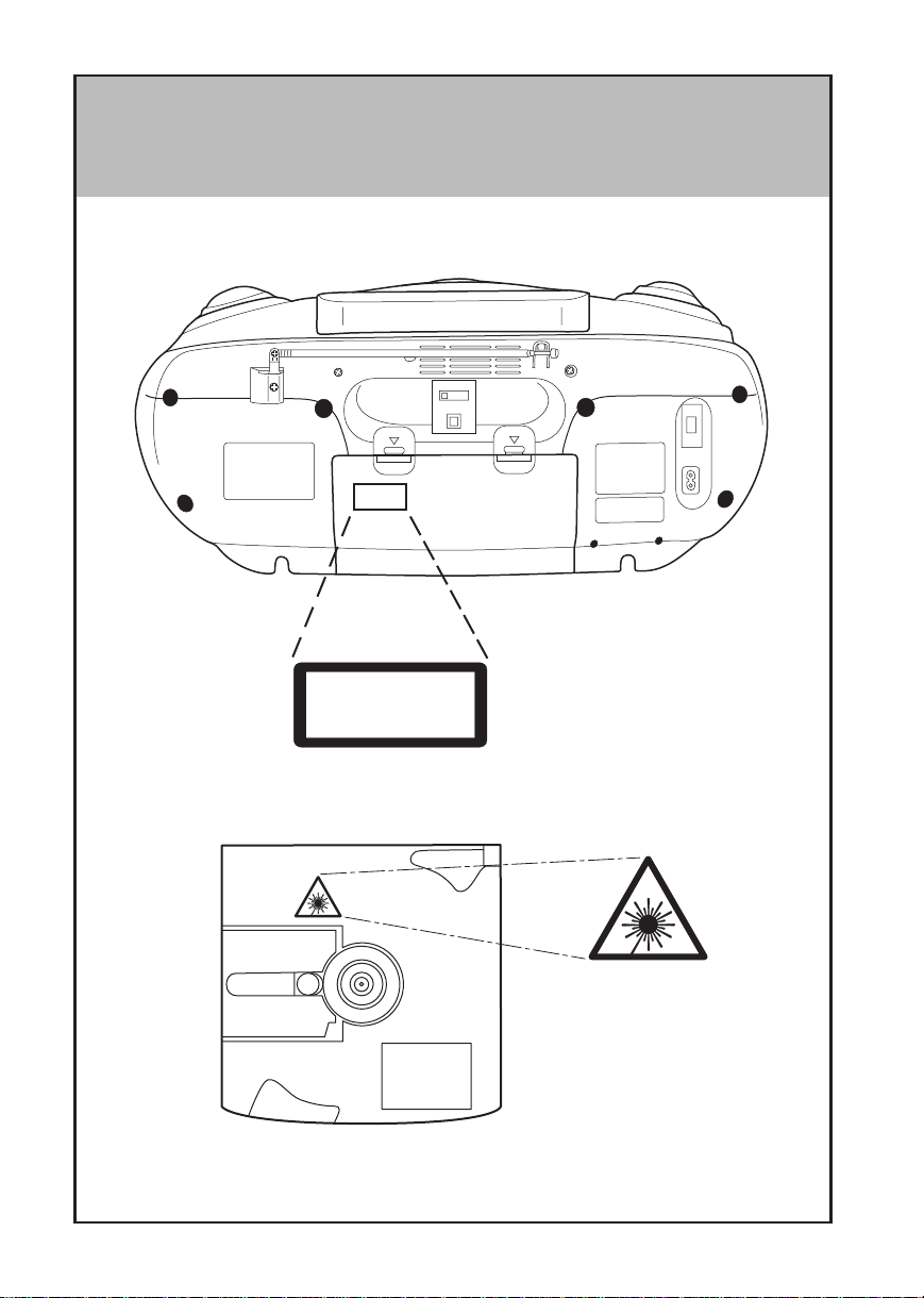
• LOCATION OF EXPLANATORY LABELS
CLASS 1 LASER PRODUCT
KLASSE 1 LASER PRODUKT
LUOKAN 1 LASER LAITE
KLASS 1 LASER APP ARAT
4
Page 5
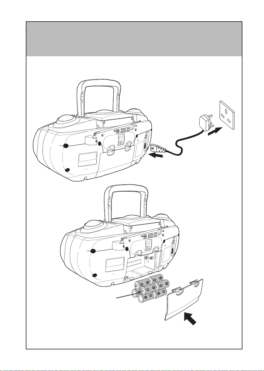
• POWER SUPPLY
MAINS SUPPLY
BA TTERY SUPPL Y
T o AC outlet
12V DC
8 x IEC R20 or
JIS R20P or “D” cell.
NOTE : When the volume drops and the tape speed slows down, it is a sign that the
batteries have to be replaced.
5
Page 6

PRECAUTIONS
• When the set is not going to be used for a long time, unplug the AC lead and remove
the batteries.
• Do not leave exhausted batteries in the compartment as they will leak and cause
corrosion and damage.
• Never open the covers or touch the inside or insert a metal object. Any of these
operations could cause an electric shock or a fault.
• When thunder starts, unplug the power cord from the AC outlet. If the set is being
used outdoors, shorten the antenna and stop using the set.
• Shorten the antenna when carrying the set. If the set is carried with the antenna
extended, it could break.
• Do not expose the unit to direct sunlight, extreme heat, and high humidity, or place it
near heat sources, the sea, or in a sandy or dusty place.
• Do not clean the cabinet of the set with strong detergents or solvents as these could
damage the surface finish.
• We discourage the use of C-120 cassette tapes as they tend to break or jam the
device.
• The apparatus shall not be exposed to dripping or splashing.
• Discs which can be played on this player have the following mark on them:
• Do not move the set suddenly from a very cold room into a warm room. When a
chilled CD player is moved suddenly to a warm location, moisture condensation may
form on the pick-up lens, preventing proper operation. In this case, wait 1 to 2 hours
before resuming play.
• During playback, if the CD player is subjected to a sudden shock or jolt, some noise
may be produced, this is not a malfunction.
• Do not place any objects in the disc compartment, it may cause damage to the
mechanism.
• Whenever moving the set, first, be sure to remove the disc from it, If the player is
moved with the disc loaded, the disc may be damaged.
• Do not store discs in high temperature, high-humidity locations. The discs may develop
warps and become unable to play. Also, discs with moisture on them may be
unplayable. Wipe any moisture off with a soft, dry cloth, and be sure discs are fully
dry before using.
• Handle the discs carefully so that fingerprints and dust do not adhere to the surface
of the discs. To clean off, use a soft cloth. Do not use a hard cloth since these will
mark the disc.
• If you switch on or off a fluorescent lamp which is placed near the set, you may hear
some interference noise; this is not a malfunction.
6
Page 7
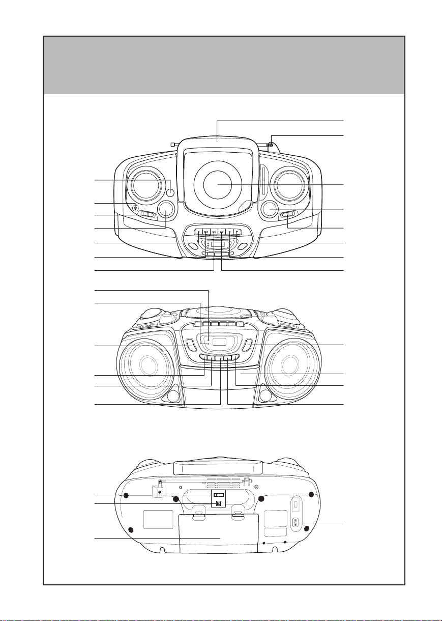
• KEY TO ILLUSTRATIONS
1
2
15
14
13
12
11
10
25
24
23
22
21
20
3
4
5
6
7
9
8
17
16
18
19
29
28
27
26
7
Page 8

KEY TO ILLUSTRA TIONS (See page 7, 8)
SET
1. Handle
2. T elescopic Antenna
3. CD Door
4. TUNING Knob
5. BAND Switch
CASSETTE DECK
6. RECORD Button (0)
7. PLAY Button (2)
8. REWIND Button (¡)
9. F.FWD Button (1)
10. STOP/EJECT Button (70)
11. P AUSE Button (8)
12. VOLUME Control
13. FUNCTION Switch
14. PHONES Jack
15. BASS BOOST Button
16. Cassette Door
CD CONTROL
17. PLA Y/PAUSE Button (6)
18. STOP Button (7)
19. ¡/¢ Button
20. 4/1 Button
21. PROGRAM Button
22. REPEAT Button
23. SURROUND MODE Button
24. SURROUND MODE Indicator
25. FM STEREO Indicator
26. AC Mains
27. Battery Door
28. (DIGITAL OUT) Optical Jack
29. BEA T CUT/FM MODE Switch
FUNCTIONS AND FEATURES
SURROUND SOUND AND BASS BOOST FEATURES
The Surround Sound feature provides enhanced four speaker output and extra wide
stereo separation. The BASS BOOST feature provides extra Bass Response, especially
at lower volume levels.
1) Press the SURROUND MODE button [23] to select this function. The Surround Indicator lights “On”.
2) Press again to turn off. The Surround Indicator will go off.
3) Dynamic BASS BOOST System.
Push the BASS BOOST button [15] to “ON” _ to obtain rich Bass sound as desired.
NOTE: If you are playing music with heavy Bass sound at loud volume levels, you may
experience distortion if the BASS BOOST feature is “ON” _. If this occurs, reduce the
volume or switch the BASS BOOST feature “OFF” —.
RADIO SECTION
RADIO AERIALS
• For FM, lengthen the telescopic aerial. To improve FM-reception, incline and turn the
aerial. Reduce its length if the FM-signal is too strong (very close to a transmitter).
• For MW and L W , the set is provided with a built-in aerial, so the telescopic aerial is not
needed. Direct the aerial by turning the whole set.
8
Page 9

STEREO/MONO (FM only)
• When an FM stereo signal is too weak or noisy for stereo listening, set the switch [29]
to the MONO position to reduce the noise.
BEAT CUT (MW and LW only)
• If beat noise is audible during the recording from an MW or LW radio programme,
switch button [29] over from [A] to [B] or from [B] to [A] to reduce the noise.
TAPE RECORDER SECTION
Use only NORMAL tapes in the cassette deck of this sound system. The characteristics
of the cassette deck mechanisms do not match other types of tape.
REWIND (¡) AND FAST FORWARD (1) BUTTONS
To rewind the tape, press the REWIND button [8]. To rapidly advance the tape, press the
F .FWD button [9]. To stop rewinding or fast forwarding, press the STOP/EJECT button [10].
PAUSE BUTTON (8)
To halt the tape temporarily during recording or playback, press the PAUSE button [11]. To
release the pause mode, press the PAUSE button [11] again.
STOP/EJECT BUTTON (70)
When this button is pressed with the tape running, the tape stops. When it is pressed in the
stop mode, the cassette holder opens.
VARIABLE MONITOR
During recording, adjustment of volume is unnecessary. A programme may by heard at any
desired volume, and the setting of the BASS BOOST Button [15] does not affect the volume
because of the “Variable Monitor” device.
CD PLAYER SECTION
4/1 AND ¡/¢ BUTTON
Skip playback
By pressing briefly the ¡/¢ [19] or 4/1 [20] buttons, you can skip to a next or
previous title, or you can select a track before starting playback.
A. During PLAY
– You can skip to the next title by pressing the ¡/¢ button once. If you want to skip
more than one track, press the ¡/¢ button more than once until the display shows
the desired track number.
9
Page 10

– If you want to repeat the running title from the beginning, press the 4/1 button
once. If you want to repeat one of the previous titles, press the 4/1 button more
than once until the display shows the required track number.
– Press and hold ¡/¢ or 4/1 button on the front panel during play, and the CD
player will start search. The player will start play when you release the button.
B. In position STOP
– In position STOP with a CD inserted you can select the desired title using the ¡/¢
or 4/1 button until the display shows the required track number. Press PLAY/
PAUSE button [17] to start playback.
Connection to an optical device
Connect the optical digital
cord to this unit after removing
the terminal cover from the
optical terminal.
OPTICAL
DIGITAL
OUT
OPTICAL
DIGITAL IN
Optical digital cord
10
MD recorder, etc.
Page 11

OPERATION (See page 13 - 20)
TO LISTEN USING HEADPHONES (See page 20)
RECORDING PROTECTION (See page 21)
MAINTENANCE (See page 21, 22)
CHECK THE FOLLOWING BEFORE CALLING FOR SERVICE
Before you jump to the conclusion that it’s out of order!
When the set is not operating properly , one is apt to assume that the set is faulty . There are,
however, many possible faults which are not directly attributable to the set itself. It is
recommended to check the following before taking the set to a Hitachi dealer.
Symptom
No AC power.
No DC power.
T ape does not run when a button is pressed.
Cassette cannot be inserted.
No recording.
Deteriorated sound or irregular tape
speed.
Slow tape speed or low volume.
Disc is not played.
Player does not operate correctly; sound
is interrupted, noise occurs and tracks
cannot be selected.
Player does not operate normally when
CD player Tape Recorder Power
control buttons are pressed.
Cause
• Is the power cord connected properly?
• Are the batteries properly inserted in
the battery compartment?
• Are the batteries exhausted?
• Is the cassette upside down?
• Is the Pause button pressed? If so,
unlock and release.
• Are the accidental-erasure prevention
tabs punched out? If so, cover the
holes with plastic tape.
• Clean heads, capstan and pressure
roller with a cleaning stick.
• Are the batteries exhausted?
• Is the disc loaded upside down?
• Is the disc scratched or warped?
• Is the pick-up lens dirty? If so, clean it
with a cleaning stick.
• Is the disc scratched or otherwise
flawed?
• Is the disc soiled?
• First press the Stop button then play
disc again.
11
Page 12

SPECIFICATIONS
RADIO SECTION
Frequency Range FM: 88-108MHz
MW: 530-1600kHz
LW: 145-275kHz
Antennas FM: Telescopic antenna
MW/L W: Built-in ferrite bar
TAPE RECORDER SECTION
Frequency Response 100 ~ 8,000 Hz
CD PLAYER SECTION
Disc used Compact Disc
Sampling Frequency 44.1kHz
Quantization Number 16bit linear/channel
Frequency Response 20 to 20,000Hz
GENERAL SPECIFICATION
Power Requirements AC 230V, 50Hz
12V DC, “D” cell or IEC R20 or JIS R20P x 8 or equiva-
lent
Power Consumption 14W in AC operation
Speakers Main: 10cm (4 in.)x2 / Tweeter: 5 cm (2 in.)x2
Power Output 2W + 2W
Outputs Headphones jack (stereo 3.5mm)
OPTICAL DIGITAL OUTPUT
Dimensions Approx. 410(L)x220(W)x165(H)mm.
Weight Approx. 5.2kg with batteries
Accessory Supplied AC power cord x1
Specifications are subject to change for performance improvement without notice.
12
Page 13

• LISTENING TO THE RADIO
BASS BOOST
1
3
For better reception
5
For MW/L W
FUNCTION
CD/RADIO OFF
CD TAPE RADIO
MIN MAX
VOLUME
2
BAND
FM MW LW
4
TUNING
For FM
6
FUNCTION
CD/RADIO OFF
CD TAPE RADIO
13
Page 14

• PLAYING A CD
BASS BOOST
1
3
5
FUNCTION
CD/RADIO OFF
CD TAPE RADIO
PLAY
2
4
6
MIN MAX
Open
Close
VOLUME
7
9
8
PLAY
FUNCTION
CD/RADIO OFF
CD TAPE RADIO
14
Page 15

• PROGRAMMING TRACK NUMBERS (For CD)
PROG
• Y ou can store at most 19 tracks in the memory in the desired sequence. You can
store each track more than once.
Operating 1 ~ 4 / page 14
1
2
4
6
PROG
PROG
PLAY
PROG
3
5
Repeat 3, 4 to program next
desired track.
7
Erasing all program
FUNCTION
CD/RADIO OFF
CD TAPE RADIO
or
Open
15
Page 16

• REPEAT PLAY (For CD)
• You can repeat playback, 1 track or all tracks.
1
2
PLAYPLAY
REP
PLAYPLAY
REP.A
PLAYPLAY
Repeat 1 track Repeat all track
1
REP
PLAYPLAY
x 2
REP.A
PLAYPLAY
2
16
Page 17

• CASSETTE PLAYBACK
12
FUNCTION
CD/RADIO OFF
CD TAPE RADIO
34
56
MIN MAX
VOLUME
BASS BOOST
17
Page 18

• RECORDING FROM THE RADIO
CD TAPE RADIO
CD/RADIO OFF
FUNCTION
1
3
5
FUNCTION
CD/RADIO OFF
CD TAPE RADIO
TUNING
2
BAND
FM MW LW
4
6
7
8
18
Page 19

• RECORDING FROM THE CD PLAYER
CD TAPE RADIO
CD/RADIO OFF
FUNCTION
PLAYPLAY
PLAYPLAY
1
3
5
2
4
6
PLAYPLAY
7
19
Page 20

• T APE ERASING
1
3
5
FUNCTION
CD/RADIO OFF
CD TAPE RADIO
2
4
• TO LISTEN USING HEADPHONES
You can connect stereo headphones having a
3.5mm plug to the socket. Inserting the plug
will disconnect the speaker.
20
Page 21

• RECORDING PROTECTION
SIDE “A”
SAFETY TAB FOR SIDE “B”
SAFETY TAB FOR SIDE “A”SIDE “B”
• MAINTENANCE (CASSETTE DECK)
CAPSTAN
PRESSURE ROLLER
CLEANING STICK
1 2
RECORD/PLAYBACK HEAD
ERASE HEAD
21
Page 22

• MAINTENANCE (CD PLAYER)
CLEANING STICK
PICKUP LENS
BLOWER
22
Page 23

MEMO
23
Page 24

Hitachi, Ltd. Tokyo, Japan
International Sales Division
THE HITACHI ATAGO BUILDING,
No. 15 –12 Nishi Shinbashi, 2 – Chome,
Minato – Ku, Tokyo 105-8430, Japan.
Tel: 03 35022111
HITACHI EUROPE LTD. HITACHI EUROPE S.A.
Dukes Meadow 364, Kifissias Ave. & 1, Delfon Str.
Millboard Road 152 33 Chalandri
Bourne End Athens
Buckinghamshire GREECE
SL8 5XF Tel: 1-6837200
UNITED KINGDOM Fax: 1-6835694
Tel: 01628 643000 Email: service.hellas@hitachi-eu.com
Fax: 01628 643400
Email: consumer-service@hitachi-eu.com
HITACHI EUROPE GmbH HITACHI EUROPE S.A.
Munich Office Gran Via Carlos III, 101 - 1
Dornacher Strasse 3 08028 Barcelona
D-85622 Feldkirchen bei München SPAIN
GERMANY Tel: 93 409 2550
Tel: +49 -89-991 80-0 Fax: 93 491 3513
Fax: +49 - 89 - 991 80 -224 Email: rplan@hitachi-eu.com
Hotline: +49 - 180 - 551 25 51 (12ct/min.)
Email: HSE-DUS.Service@Hitachi-eu.com
HITACHI EUROPE AB
HITACHI EUROPE SRL Box 77
Via T. Gulli n.39 S-164 94 KISTA
20147 MILAN SWEDEN
ITALY
Tel: 02 487861 Fax: 08 562 711 11
Fax: 02 48786381
Servizio Clienti
Tel. 02 38073415
Email: customerservice.italy@hitachi-eu.com
HITACHI EUROPE LTD.
HITACHI EUROPE S.A.S Norwegian Branch Office
Lyon Office Strandveien 18
B.P. 45, 69671 Bron Cedex 1366 Dysaker
FRANCE NORWAY
Tel: 04 72 14 29 70 Tel: 02205 9060
Fax: 04 72 14 29 99 Fax: 02205 9061
Email: france.consommateur@hitachi-eu.com Email csgnor@hitachi-eu.com
ITEM N.V./S.A. (INTERNATIONAL TRADE FOR
ELECTRONIC MATERIAL & MEDIA N.V./S.A)
UCO Tower – Bellevue, 17
B – 9050 GENT
BELGIUM (for BENELUX)
Tel: 09 230 48 01
Fax: 09 230 96 80
Email:
www.hitachi-consumer-eu.com
hitachi.item@skynet.be
Tel: 08 562 711 00
Email: csgswe@hitachi-eu.com
 Loading...