

Page 1
ENGLISH
DEUTSCH
FRANÇAIS
ITALIANO
ESPAÑOL
NEDERLANDS
NORSK
TECHNICAL
PORTGÊS
Liquid Crystal Projector
CPX980W CPX985W
USER'S MANUAL
Please read this user's manual thoroughly to ensure correct usage through understanding.
BEDIENUNGSANLEITUNG
Bitte lessen Sie diese Bedienungsanleitung zugunsten der korrekten Bedienung
aufmerksam.
MANUEL D'UTILISATION
Nous vous recommandons de lire attentivement ce manuel pour bien assimiler le
fonctionnement de l'appareil.
MANUALE D'ISTRUZIONI
Vi preghiamo voler leggere attentamente il manuale d'sitruzioni in modo tale da poter
comprendere quanto riportato ai fini di un corretto utilizzo del proiettore.
MANUAL DE USUARIO
Lea cuidadosamente este manual del usuario para poder utilizar corretamente el
producto.
GEBRUIKSAANWIJZNG
Lees voor het qebruik alstublieft deze handleiding aandachtig door, om volledig profijt te
hebben van de uitgebreide mogelijkheden.
BRUKERHÅNDBOK
Vennligst les denne bruksanvisningen grundig for å være garantert driftssikker bruk.
INSTRUÇÕES DO PROPRIETÁRIO
Para assegurar o uso correto do equipamento, por favor leia atentamente este manual do
usuário.
TECHNICAL
REGULATORY NOTICES
Page 2

ENGLISH
DEUTSCH
FRANÇAIS
ITALIANO
ESPAÑOL
NEDERLANDS
NORSK
PORTGÊS
SAFETY INSTRUCTIONS
USER’S MANUAL – Separate Volume
Before using this product, please read and understand the Safety Instructions thoroughly
to ensure correct usage.
After reading, store the Safety Instructions together with the USER'S MANUAL.
SICHERHEITSVORSCHRIFTEN
BEDIENUNGSANLEITUNG – Andere Band
Bevor Sie dieses Produkt benutzen, sollten Sie die Sicherheitsvorschriften gründlich
durchlesen und sich mit ihnen vertraut machen, um korrekten Gebrauch zu
gewährleisten. Bewahren Sie die Sicherheitsvorschriften nach dem Durchlesen
zusammen mit der BEDIENUNGSANLEITUNG auf.
CONSIGNES DE SÉCURITÉ
MANUEL D’UTILISATION – Volume Annexe
Avant d'utiliser ce produit, veuillez lire attentivement les consignes de sécurité afin
d'utiliser l'appareil dans les meilleures conditions. Une fois que vous avez terminé,
rangez les Consignes de sécurité avec le MANUEL D'UTILISATION.
ISTRUZIONI DI SICUREZZA
MANUAL D’ISTRUZIONI – Volume Separato
Prima di usare questo prodotto, leggere attentamente ed assimilare le istruzioni di
sicurezza per garantire un corretto uso dello stesso. Dopo averle lette riporre le istruzioni
di sicurezza con il MANUALE D'ISTRUZIONI.
INSTRUCCIONES DE SEURIDAD
MANUAL DE USUARIO – Volumen Separdo
Antes de usar este producto, se recomienda leer y comprender cabalmente todas las
instrucciones de seguridad para poderlo utilizar correctamente. Después de leer las
instrucciones de seguridad, guárdelas junto con el MANUAL DE USUARIO.
VEILIGHEIDSINSTRUCTIES
GEBRUIKSAANWIJZNG – Afzonder Band
Lees voor gebruik de Veiligheidsinstructies aandachtig door zodat u het apparaat op de
juiste wijze behandelt. Bewaar de Veiligheidsinstructies samen met de
GEBRUIKSAANWIJZNG voor het geval u deze in de toekomst nogmaals nodig hebt.
SIKKERHETSINSTRUKSJONER
BRUKERHÅNDBOK – Separate Håndbok
Før dette produktet tas i bruk, må "Sikkerhetsregler" til fulle leses og forstås for å sikre
korrekt bruk. Etterpå må de oppbevares sammen med BRUKERHÅNDBOK.
INSTRUÇÕES DE SEGURANÇA
INSTRUÇÕES DO PROPRIETÁRIO – Folheto à Parte
Antes de usar este produto, leia atentamente as Instruções de Segurança para
assegurar o uso correto do equipamento. Após a leitura, guarde as Instruções de
Segurança juntamente com o INSTRUÇÕES DO PROPRIETÁRIO.
Liquid Crystal Projector
Page 3
ENGLISH
ENGLISH - 1
BEFORE USING
About the Symbols
Various symbols are used in this manual, the user’s manual and on the product itself to
ensure correct usage, to prevent danger to the user and others, and to prevent property
damage. The meanings of these symbols are described below. It is important that you
read these descriptions thoroughly and fully understand the contents.
Typical Symbols
This symbol indicates an additional warning (including cautions). An
illustration is provided to clarify the contents.
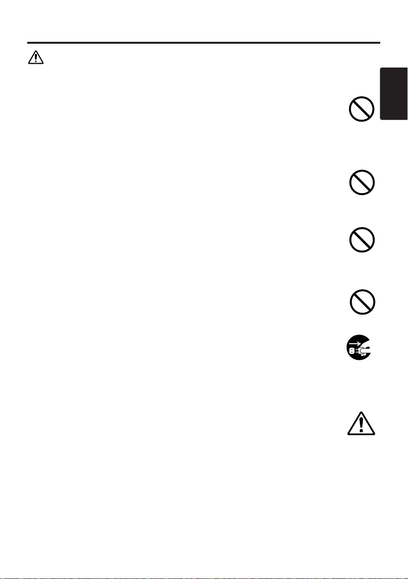
This symbol indicates a prohibited action. The contents will be clearly
indicated in an illustration or nearby (the symbol to the left indicates that
disassembly is prohibited).
This symbol indicates a compulsory action. The contents will be clearly
indicated in an illustration or nearby (the symbol to the left indicates that the
power plug should be disconnected from the power outlet).
Warning
This symbol indicates information that, if ignored, could
possibly result in personal injury or even death due to
incorrect handling.
Caution
This symbol indicates information that, if ignored, could
result possibly in personal injury or physical damage due to
incorrect handling.
NOTE : "Remote control transmitter" may be called "Remote controller" in the "USER'S
MANUAL".
Page 4
ENGLISH - 2
SAFETY PRECAUTIONS
WARNING
Never use the projector if a problem should occur.
Abnormal operations such as smoke, strange odor, no image, no sound,
excessive sound, damaged casing or elements or cables, penetration of
liquids or foreign matter, etc. can cause a fire or electrical shock.
In such case, immediately turn off the power switch and then disconnect the
power plug from the power outlet. After making sure that the smoke or odor
has stopped, contact your dealer. Never attempt to make repairs yourself
because this is dangerous this could be dangerous.
* The power outlet should be close to the projector and easily accessible.
Do not insert liquids or foreign object.
Penetration of liquids or foreign objects could result in fire or electrical shock.
Use special caution in households where children are present.
If liquids or foreign object should enter the projector, immediately turn off the
power switch, disconnect the power plug from the power outlet and contact your
dealer.
* Do not place the projector in a bathroom.
* Do not expose the projector to rain or moisture.
* Do not place flower vases, pots, cups, cosmetics, liquids such as water, etc on
or around the projector.
* Do not place metals, combustibles, etc on or around the projector.
Never modify.
The projector contains high voltage components. Modification could result in
fire or electrical shock.
* Never open the cabinet.
* Ask your dealer to repair and clean insider.
Do not give the projector any shock or impact.
If the projector should be shocked and/or broken, it could result in an injury, and
continued use could result in fire or electrical shock.
If the projector is shocked, immediately turn off the power switch, disconnect the
power plug from the power outlet and contact your dealer.
Disconnect the
plug from the
power outlet.
Do not
disassemble.
Page 5
ENGLISH
ENGLISH - 3
SSAAFFEETTYY PPRREECCAAUUTTIIOONNSS ((ccoonnttiinnuueedd))
WARNING
Do not place the projector on an unstable surface.
If the projector should be dropped and/or broken, it could result in an injury, and
continued use could result in fire or electrical shock.
* Do not place the projector on an unstable, slant or vibrant surface such as a
wobbly or inclined stand.
* Use the caster brakes placing the projector on a stand with casters.
* Do not place the projector in the side up position, the lens up position or the
lens down position.
Be cautious of High temperatures of the projector.
High temperatures are generated when the lamp is lit. It could result in fire or
burn. Use special caution in households where children are present.
Do not touch about the lens, air fans and ventilation openings during use or
immediately after use, to prevent a burn. Take care of ventilation.
* Keep a space of 30 cm or more between the sides and other objects such as
walls.
* Do not place the projector on the metallic table.
* Do not place anything about the lens, air fans and ventilation openings of the
projector.
* Never block the air fan and ventilation openings.
* Do not use with the ventilation opening facing downwards.
* Do not cover the projector with a tablecloth, etc.
* Do not place the projector on a carpet or bedding.
Never look through the lens or openings when the lamp is on.
The powerful light could adversely affect vision. Use special caution in
households where children are present.
Use only the correct power outlet.
Incorrect power supply could result in fire or electrical shock. Use only the
correct power outlet depending on the indication on the projector and the safety
standard.
* The enclosed power cord must be used depending on the power outlet to be
used.
Be cautious of the power cord connection.
Incorrect connection of the power cord could result in fire or electrical shock.
* Do not touch the power cord with a wet hand.
* Check that the connecting portion of the power cord is clean (with no dust),
before using. Use a soft and dry cloth to clean the power plug.
* Insert the power plug into a power outlet firmly. Avoid using a loose, unsound
outlet or contact failure.
Page 6
ENGLISH - 4
SSAAFFEETTYY PPRREECCAAUUTTIIOONNSS ((ccoonnttiinnuueedd))
WARNING
Be careful in handling the the light source lamp.
Incorrect handling the lamp could result in explosion.
* Since the lamp is made of glass, do not apply shock to it and not scratch it.
* When replacing lamp, turn off and remove AC cord, waite 45 minutes to let
lamp cool. High-pressure lamp when hot, may explode if improperly handled.
* The lamp has a service life. For details, read the user's manual. Please contact
your dealer or service company for replacement. Do not use old use old lamp.
This could also cause explosion of the lamp.
Be careful in handling the power cord and external connection
cables.
If you keep using a damaged the power cord or cables, it can cause a fire or
electrical shock. Do not apply too much heat, pressure or tension to the power
cord and cables.
If the power cord or cables is damaged (exposed or broken core wires, etc.),
contact your dealer.
* Do not place the projector or heavy objects on the power cord and cables. Also,
do not place a spread, cover, etc, over them because this could result in the
inadvertent placing of heavy objects on the concealed power cord or cables.
* Do not pull the power cord and cables. When connecting and disconnecting the
power cord or cables, do it with your hand holding the plug or connector.
* Do not place the cord near the heater.
* Avoid bending the power cord sharply.
* Do not attempt to work on the power cord.
Be careful in handling the battery of the remote control transmitter.
Incorrect handling of the battery could result in fire or personal injury. The
battery may explode if not handled properly.
* Keep the battery away from children and pets. If swallowed consult a physician
immediately for emergency treatment.
* Do not allow the battery in a fire or water.
* Avoid fire or high-temperature environment.
* Do not hold the battery with the metallic tweezers.
* Keep the battery in a dark, cool and dry play.
* Do not short circuit the battery.
* Do not recharge, disassemble or solder the battery.
* Do not give the battery a physical impact.
* Use only the battery specified in the user’s manual.
* Make sure the plus and minus terminals are correctly aligned when loading the
battery.
* If you observe a leakage of the battery, wipe out the flower and then replace
the battery. If the flower adheres your body or clothes, rinse well with water.
* Obey the local laws on disposing the battery.
Page 7
ENGLISH
ENGLISH - 5
SSAAFFEETTYY PPRREECCAAUUTTIIOONNSS ((ccoonnttiinnuueedd))
CAUTION
Be careful in moving the projector.
Neglect could result in an injury or damage.
* Do not move the projector during use. Before moving, disconnect the power
cord and all external connections, and close the slide lens door.
* Avoid any impact or shock to the projector.
* For carrying, use the enclosed carrying bag if provided, depending on the
manual of the carrying bag.
Do not put anything on top of the projector.
Placing anything on the projector could result in loss of balance or falling, and
cause an injury or damage. Use special caution in households where children are
present.
Avoid a humid or dusty place.
Placing the projector in a highly humid, dusty place, oily soot or corrosive gas
could result in fire or electrical shock.
* Do not place near the kitchen, a humidifier or other place where there is oily
smoke or humidity.
Avoid a high temperature environment.
The heat could have adverse influence on the cabinet of the projector and other
parts. Do not place the projector, the remote control transmitter and other parts
in direct sunlight or near a hot object such as heater, etc.
Remove the power cord for complete separation.
* For safety purposes, disconnect the power cord if the projector is not to be
used for prolonged periods of time.
* Before cleaning, turn off and unplug the projector. Neglect could result in
fire or electrical shock.
Ask your dealer to cleaning inside of the projector about every two
years.
Accumulations of dust inside the projector cause result in fire or malfunction.
Cleaning inside is more effective if performed before every humid periods such
as rainy season.
* Do not clean inside yourself because it is dangerous.
Disconnect the
plug from the
power outlet.
Page 8

ENGLISH - 6
SSAAFFEETTYY PPRREECCAAUUTTIIOONNSS ((ccoonnttiinnuueedd))
NOTE
Do not give the remote control transmitter any physical impact.
A physical impact could cause damage or malfunction of the remote control
transmitter.
* Take care not to drop the remote control transmitter.
* Do not place the projector or heavy objects on the remote control transmitter.
Take care of the lens.
* Close the slide lens door to prevent the lens surface being scratched when the
projector is not used.
* Do not touch the lens to prevent fog or dirt of the lens that cause deterioration
of display quality.
* Use commercially available lens tissue to clean the lens (used to clean cameras,
eyeglasses, etc.). Be careful not to scratch the lens with hard objects.
Clean the air filter about every 100 hours.
When the air filter becomes clogged with dust, etc., the projector may display the
message such as “CHECK THE AIR FLOW” or turn off the projector, to prevent
the internal heat level rising. Take care of the air filter to normal ventilate.
* Do not turn on the projector without air filter.
* If the air filter is damaged or lost, order the air filter specified in the user’s
manual to your dealer.
Take care of the cabinet and the remote control transmitter.
Incorrect care could have adverse influence such as discoloration, peeling paint,
etc.
* Use a soft cloth to clean the cabinet and control panel of the projector and the
remote control transmitter. When excessively soiled dilute a neutral detergent
in water, wet and wring out the soft cloth and afterward wipe with a dry soft
cloth. Do not use undiluted detergent directly.
* Do not use an aerosol sprays, solvents, volatile substances or abrasive cleaner.
* Before using chemical wipes, be sure to read and observe the instructions.
* Do not allow long-term close contact with rubber or vinyl.
Page 9

ENGLISH
ENGLISH - 7
SSAAFFEETTYY PPRREECCAAUUTTIIOONNSS ((ccoonnttiinnuueedd))
NOTE
Avoid strong rays.
Any strong ray (such as direct rays of the sun or room lighting) onto the remote control
transmitter sensors could invalidate the remote control transmitter.
Avoid radio interference.
Any interfering radiation could cause disordered image or noises.
* Avoid radio generator such as a mobile telephone, transceiver, etc. around the projector.
About displaying characteristic.
The display condition of the projector (such as color, contrast, etc.) depends on
characteristic of the screen, because the projector uses a liquid crystal display panel. The
display condition can differ from the display of CRT.
* Do not use a polarized screen. It can cause red image.
Turn the power on/off in right order.
To prevent any trouble, turn on/off the projector in right order mentioned below unless
specifying.
* Power on the projector before the computer or video tape recorder.
* Power off the projector after the computer or video tape recorder.
Take care not to fatigue your eyes.
Rest the eyes periodically.
Set the sound volume at a suitable level to avoid bothering other people.
* It is better to keep the volume level low and close the windows at night to protect the
neighborhood environment.
Connecting with notebook computer
When connecting with notebook computer, set to valid the RGB external image output (setting CRT
display or simultaneous display of LCD and CRT).
Please read instruction manual of the notebook for more information.
Page 10

ENGLISH
Liquid Crystal Projector
USER'S MANUAL
USER'S MANUAL
ENGLISH-1
Thank you for purchasing this liquid crystal projector.
CONTENTS
CONTENTS
Page
FEATURES .......................................2
BEFORE USE ...................................2
Contents of Package ..............................2
Part Names.............................................3
Loading the Batteries..............................5
INSTALLATION ................................6
Installation of the Projector and Screen
........6
Angle Adjustment ...................................6
Cabling ...................................................7
Power Connection ..................................8
Example of System Setup ......................8
Plug & Play.............................................8
OPERATIONS...................................9
Power On...................................................9
Power Off
................................................9
Basic Operation....................................10
Setup Menu ..........................................12
Input Menu............................................13
Image Menu..........................................14
Options Menu .......................................15
No Signal Menu....................................16
MAINTENANCE ..............................17
Lamp.....................................................17
Air Filter ................................................19
Other Maintenance...............................19
Page
TROUBLESHOOTING ....................20
OSD Message ......................................20
Indicators Message ..............................21
Symptom ..............................................22
SPECIFICATIONS...........................23
WARRANTY AND AFTER-SERVICE
......24
.......................................................................................
TABLES
Table 1. Installation Reference.................6
Table 2. Cabling .......................................7
Table 3. Basic Operations ......................10
Table 4. Setup Menu ..............................12
Table 5. Input Menu................................13
Table 6. Image Menu..............................14
Table 7. Options Menu ...........................15
Table 8. No Signal Menu........................16
Table 9. OSD Message ..........................20
Table 10. Indicator Message ..................21
Table 11. Symptom ................................22
Table 12. Specifications .........................23
.......................................................................................
For "TECHNICAL" and "REGULATORY
NOTICE", see the end of this manual.
• The information in this manual is subject to change without notice.
• The manufacturer assumes no responsibility for any errors that may appear in this manual
• The reproduction, transmission or use of this document or contents is not permitted without
express written authority.
TRADEMARK ACKNOWLEDGMENT : PS/2, VGA and XGA are registered trademarks of
International Business Machines Corporation. Apple, Mac and ADB are registered trademarks of
Apple Computer, Inc. VESA and SVGA are trademarks of the Video Electronics Standard
Association. Windows is a registered trademark of Microsoft Corporation. Carefully observe the
trademarks and registered trademarks of all companies, even when not mentioned.
NOTE
WARNING • Please read the accompanying manual “SAFETY
INSTRUCTIONS” and this “USER'S MANUAL” thoroughly to ensure correct
usage through understanding. After reading, store this instruction manual in a
safe place for future reference.
Page 11
ENGLISH-2
FEATURES
FEATURES
This liquid crystal projector is used to project various computer signals as well as NTSC / PAL /
SECAM video signals onto a screen. Little space is required for installation and large images can
easily be realized.
Outstanding Brightness
The UHB lamp and high-efficiency optical system assure a high level of brightness.
Partial Magnification Function
Interesting parts of images can be magnified for closer viewing.
Distortion Correction Function
Distortion-free images are quickly available.
BEFORE USE
BEFORE USE
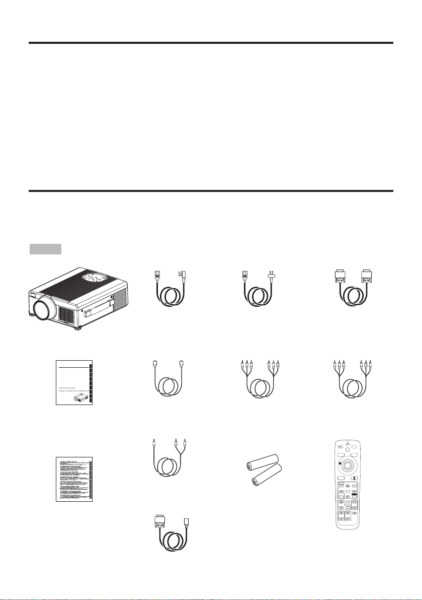
Contents of package
Make sure all of the following items are included in the package. If anything is missing, please
contact your dealer.
• Keep the original packing material for future reshipment.
NOTE
Projector
G
S
C
O
S
S
S
C
C
G
U
Pl
ghl
g.
G
g
aufmerksam.
MANUEL D'UTILISA
TION
N
l
e
f
il.
R
UZIONI
Vi
ghi
p
ili
.
O
L
ili
l
prod
GEBR
G
L
blieft d
iding
dig
fij
e
hebb
lijkheden.
R
U
H
Å
OK
å
æ
ikk
k.
R
U
ÇÕ
R
O
O
usu
á
io
.
TO
User’s Manual
(this manual)
Safety Instructions
Power Cord
(UK Type)
Power Cord
(Europe Type)
RGB Cable
Video/Audio Cable
(with white lead)
Mouse cable
(PS/2)
Remote Control
Transmitter
Batteries
for Remote Control
Transmitter
Component
Video Cable
(with green lead)
Audio Cable
(Stereo Mini)
S-Video Cable
USER'S MAN
ease read this user's manual thorou
y to ensure correct usage through understandin
BEDIENUNGSANLEITUN
Bitte lessen Sie diese Bedienungsanleitung zugunsten der korrekten Bedienun
TION
ous vous recommandons de lire attentivement ce manuel pour bien assimiler
onctionnement de l'appare
MANUALE D'IST
pre
amo voler leggere attentamente il manuale d'sitruzioni in modo tale da poter
com
rendere quanto riportato ai fini di un corretto ut
zzo del proiettore
MANUAL DE USUARI
ea cuidadosamente este manual del usuario para poder ut
ucto
UIKSAANWIJZN
ees voor het qebruik alstu
eze handle
aandachtig door, om volle
en van de uitgebreide moge
B
KER
NDB
re garantert driftss
INST
ES DO P
PRIETRI
r
TECHNICAL
TO
NOTICES
H
LI
EN
H
EUTS
TALIAN
zar corretamente e
L
PA
pro
t t
E
er bru
NEDERLAND
K
NOR
ORT
AL
HNI
TE
VIDEO
STANDBY/ON
LASER
RGB
BLANK
AUTO
MENU
PinP
MAGNIFY
MENU SELECT
FREEZE
POSITION
RESET
VOLUME
OFF
MUTE
ZOOMFOCUS
Page 12
ENGLISH-3
BBBBEEEEFFFFOOOORRRREEEE UUUUSSSSEEEE ((((ccccoooonnnnttttiiiinnnnuuuueeeedddd))
))
ENGLISH
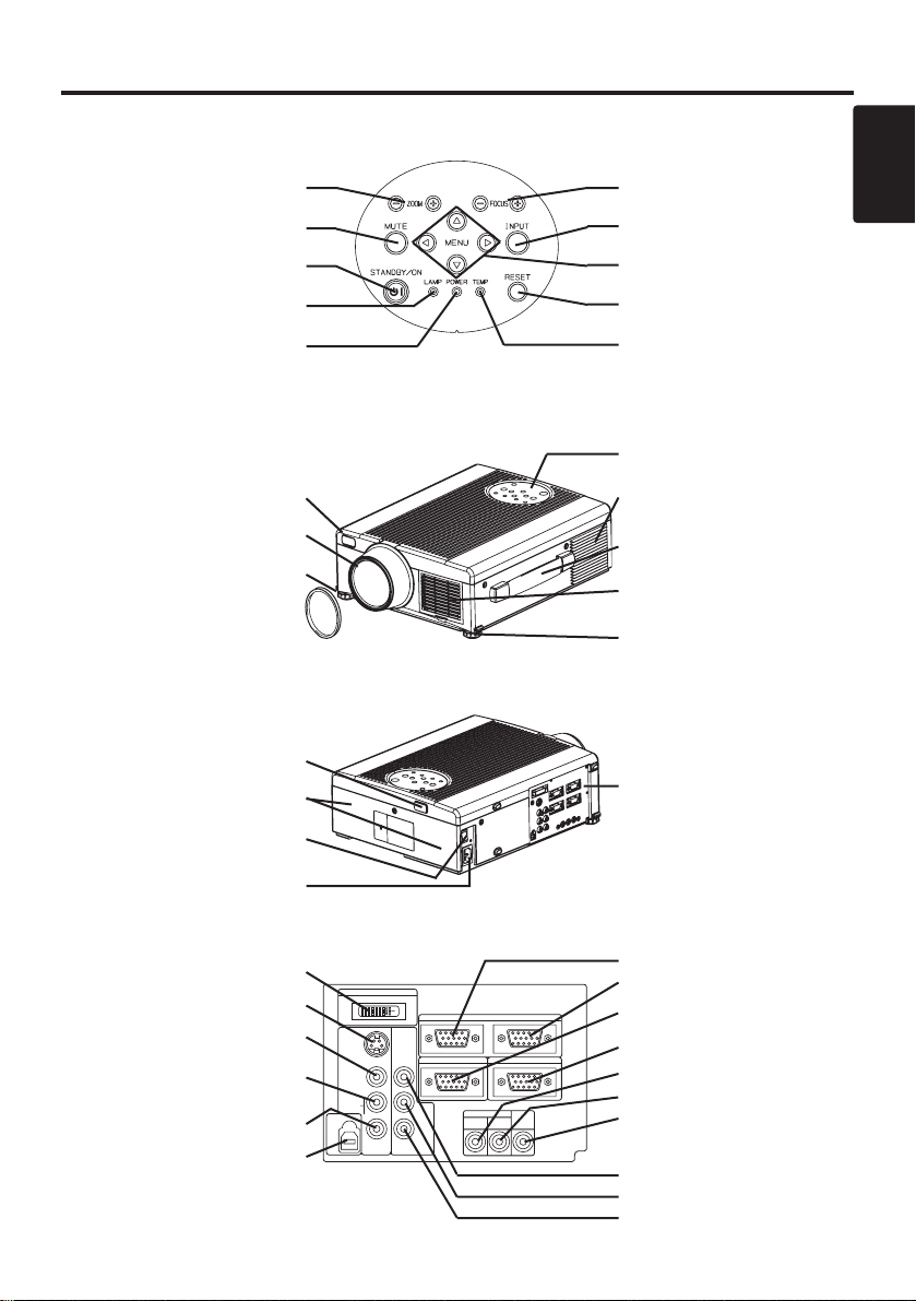
Part Names
Control Panel
(Refer to P.9 "OPERATIONS")
Front/Right View
Rear/Left View
Terminal Panel
(Refer below)
Terminal
Panel
DIGITAL Terminal
S-VIDEO Terminal
VIDEO Terminal
AUDIO(MONO)/L
Terminal
AUDIO R Terminal
USB Terminal
ZOOM Button
MUTE Button
STANDBY/ON Button
LAMP Indicator
POWER Indicator
FOCUS Button
INPUT Button
MENU Button
RESET Button
TEMP Indicator
Remote Control Sensor
Lens
Foot Adjuster
Lens Cap
Control Panel
Ventilation Openings
(exhaust)
Carrying Handle
Air Filter and Intake
for the Cooling Fan
Foot Adjuster
Remote Control Sensor
Speaker
Power Switch
AC Inlet
(to Power Cord)
RGB IN 1 Terminal
RGB IN 2 Terminal
RGB OUT Terminal
CONTROL Terminal
AUDIO IN RGB1 Terminal
AUDIO IN RGB2 Terminal
AUDIO OUT Terminal
COMPONENT VIDEO
Y Terminal
C
B/PB Terminal
C
R/PR Terminal
DIGITAL
S-VIDEO
COMPO
VIDEO
(MONO)/L
AUDIO
R
USB
RGB IN 2
NENT
VIDEO
RGB OUT
CONTROL
AUDIO IN AUDIO
C
B/PB
CR/PR
RGB 1
DIGITAL
OUT
RGB 2
Page 13
ENGLISH-4
BBBBEEEEFFFFOOOORRRREEEE UUUUSSSSEEEE ((((ccccoooonnnnttttiiiinnnnuuuueeeedddd))
))
Part Names (continued)
S
T
A
N
D
B
Y
/O
N
LASER
VIDEO
BLANK
RGB
AUTO
MENU
MENU SELECT
POSITION
R
E
SET
FR
EEZE
MAGNIFY
PinP
OFF
VOLUME
MUTE
ZOOM
FOCUS
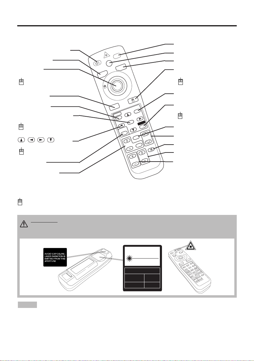
REMOTE CONTROL TRANSMITTER
(Refer to P.9 "OPERATIONS")
To prevent any malfunction;
• Do not give the remote control transmitter any physical impact. Take care not to drop.
• Do not place the heavy objects on the remote control transmitter.
• Do not wet the remote control transmitter or place it on any wet object.
• Do not place the remote control transmitter close to the cooling fan of the projector.
• Do not disassemble the remote control transmitter in case of malfunction. Please bring it to the
service station.
NOTE
STANDBY/ON Button
LASER Button
BLANK Button
Disk Pad
Used to operate the
mouse shift function and
left click function.
AUTO Button
MENU Button
MENU SELECT Button
Used to click the left
mouse button.
, , , Button
Used to operate the
mouse shift function.
MAGNIFY Button
VIDEO Button
RGB Button
MOUSE / RIGHT Button
Used to click the right
mouse button.
RESET Button
Used to click the right
mouse button.
VOLUME Button
FREEZE Button
MUTE Button
POSITION Button
ZOOM Button
These functions works when the mouse control function is activated. Remember, the POSITION,
BLANK ON and MENU ON functions disable the mouse control function.
WARNING • The laser pointer of the remote control transmitter is used in
place of a finger or rod. Never look directly into the laser beam outlet or point
the laser beam at other people. The laser beam can cause vision problems.
FOCUS Button
PinP Button
CAUTION
LASER RADIATIONDO NOT STARE INTO BEAM
WAVE LENGTH: 650nm
MAX . OUTPUT: 1mW
CLASS 2 LASER PRODUCT
RADIAZIONI LASER
NON GUARDARE NEL RAGGIO LUCE
APPARECCHIO LASER DI CLASSE 2
RAYONNEMENT LASER
NE PAS REGARDER DANS
LE FAISCEAU APPAREIL
A LASER DE CLASSE 2
LASER-STRAHLUNG
NICHT IN DEN STRAHL
BLICKEN LASER KLASSE2
MANUFACTURED
PLACE OF
MANUFACTURER:A
MADE IN JAPAN
IEC60825-1:1993+A1:1997
Page 14
ENGLISH-5
BBBBEEEEFFFFOOOORRRREEEE UUUUSSSSEEEE ((((ccccoooonnnnttttiiiinnnnuuuueeeedddd))
))
ENGLISH
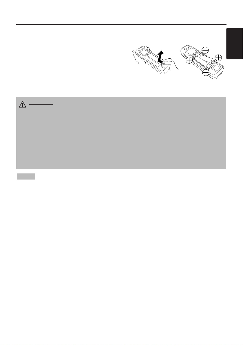
Loading the Batteries
Install the AA batteries into the remote control
transmitter.
1. Remove the battery cover.
Push the knob while lifting up the battery cover.
2. Load the batteries.
Make sure the plus and minus poles are correctly
oriented.
3. Close the battery cover.
1
2
Replace the batteries when remote control transmitter operation becomes difficult.
NOTE
CAUTION • Use only the specified batteries with this remote control
transmitter. Also, do not mix new and old batteries. This could cause in
battery cracking or leakage, which could result in fire or personal injury.
• When loading the batteries, make sure the plus and minus terminals are
correctly oriented as indicated in the remote control transmitter. Incorrect
orientation could cause battery cracking or leakage, which could result in
personal injury or pollution of the surrounding environment.
• When you dispose the battery, you obey the law in the relative area or country.
• Keep the battery away from children and pets.
• When not to be used for an extended period, remove the batteries from the
remote control transmitter.
Page 15
ENGLISH-6
INSTALLATION
INSTALLATION
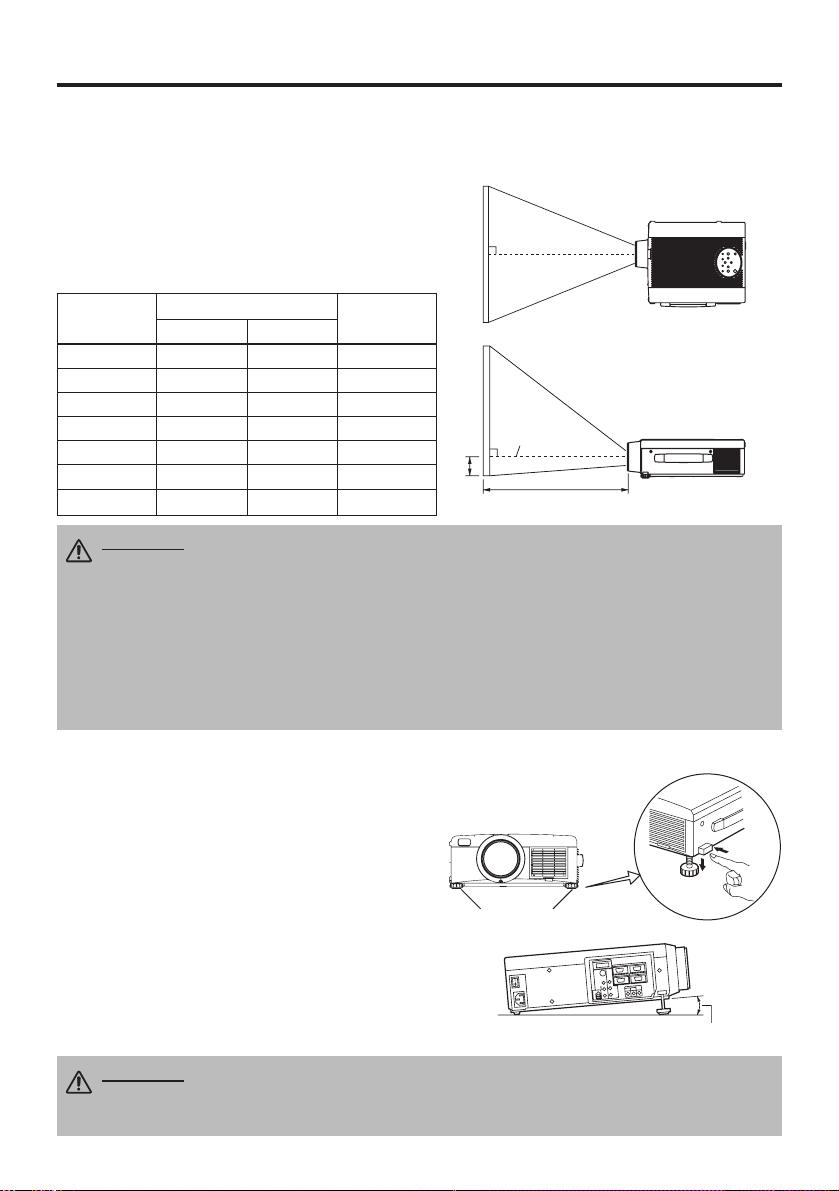
Installation of the Projector and Screen
Refer to the drawing and table below for determining of the screen size and projection distance.
Top View
Side View
Screen size
[inches (m)]
a [inches (m)]
b
[inches (cm)]
Min. Max.
40 (1.0) 55 (1.4) 73 (1.9) 1 (3)
60 (1.5) 85 (2.2) 114 (2.9) 2 (4)
80 (2.0) 114 (2.9) 151 (3.8) 2 (6)
100 (2.5) 144 (3.7) 191 (4.9) 3 (7)
120 (3.0) 176 (4.5) 231 (5.9) 3 (9)
150 (3.8) 220 (5.6) 282 (7.2) 4 (11)
200 (5.0) 291 (7.4) 386 (9.8) 6 (15)
Angle Adjustment
Use the foot adjusters on the bottom of the
projector to adjust the projection angle. It is
variable within 0˚ to 9˚ approximately.
1. Lift up the front side of the projector, and
pressing the foot adjuster button, adjust the
projection angle.
2. Release the button to lock at the angle to be
fixed.
3. Make the foot adjusters screw for fine
adjustment. Do not force the adjusters to make
screw. This could damage the adjusters or
cause the lock to fail.
Foot Adjusters
The projection distances shown in the table below
are for full size (1024 x 768 dots).
a: Distance from the projector to the screen. (±10%)
b: Distance from the lens center to the bottom of the
screen. (±10%)
Table 1. Installation Reference
b
a
Lens center
Screen
CAUTION • Install the projector in a suitable environment according to
instructions of the accompanying manual “SAFETY INSTRUCTIONS” and this
manual.
• Please basically use liquid crystal projector at the horizontal position.
If you use
liquid crystal projector by the lens up position, the lens down position and the side up
position, this may cause the heat inside to build up and become the cause of damage.
Be especially careful not to install it with ventilation holes blocked.
• Do not install LCD projector in smoke effected environment. Smoke residue may
buildup on critical parts (i.e.LCD panel, Lens Assy etc.).
CAUTION • Do not release the foot adjuster button unless the projector is
being held; otherwise, the projector could overturn or the fingers could get
caught and cause personal injury.
Variable within the range of approximately 0° - 9°
Page 16

ENGLISH-7
ENGLISH
IIIINNNNSSSSTTTTAAAALLLLLLLLAAAATTTTIIIIOOOONNNN ((((ccccoooonnnnttttiiiinnnnuuuueeeedddd))
))
• Before connecting, read instruction manuals of the devices to be connected, and make sure that the
projector is compatible with the device.
• Secure the screws on the connectors and tighten.
• For some RGB input modes, the optional Mac adapter is necessary.
• To select the digital RGB input, the comuter may need some settings. See the manuals of the computer for
details.
• Some computers may have multiple display screen modes. Use of some of these modes will not be possible
with this projector.
• Refer to the “TECNICAL” section for the pin assign of connectors and RS-232C communication data.
• When the DIGITAL terminal is used, the RGB OUT terminal may not function.
NOTE
CAUTION • Incorrect connecting could result in fire or electrical shock.
Please read this manual and the separate “SAFETY INSTRUCTIONS”.
• Before connecting, turn off to all devices to be connected, except for the USB
cable.
• The cables may have to be used with the core set to the projector side. Use the
cables which are included with the projector or specified.
Cabling
Refer to the table below for connecting each terminal of the projector to each device.
Table 2. Cabling
Function Terminal Cable
Analog RGB input
RGB IN 1
Accessory RGB cable or optional RGB
cable with D-sub 15-pin shrink jack and
inch thread screws
RGB IN 2
Analog RGB output RGB OUT
Digital RGB input DIGITAL
Optional digital RGB cable with inch thread
screws
Audio input
(from the computer)
AUDIO IN [RGB 1] / [DIGITAL]
(interlocked with RGB IN 1 or
DIGITAL)
Accessory audio cable with stereo mini jack
AUDIO IN [RGB 2]
(interlocked with RGB IN 2)
PS/2 mouse control
CONTROL
Accessory PS/2 mouse cable
ADB mouse control Optional ADB mouse cable
Serial mouse control Optional Serial mouse cable
RS-232C communication Optional RS-232C cable
USB mouse control USB Optional USB cable
S-video input S-VIDEO
Accessory S-video cable with mini DIN 4pin jack
Video input VIDEO Accessory video/audio cable
Component video input
COMPONENT VIDEO Y
Accessory component video cableCOMPONENT VIDEO CB/PB
COMPONENT VIDEO CR/PR
Audio input
(from video equipment)
AUDIO (MONO)/L
Accessory video/audio cable or optional
audio cable with RCA jack
AUDIO R
Audio output AUDIO OUT Optional audio cable with stereo mini jack
Page 17

Example of system setup
S-Video Tape
Recorder
Computer (desktop type)
Computer
(notebook type)
• When connecting with notebook computer, set to valid the RGB external image output
(setting CRT display or simultaneous display of LCD and CRT). Please read instruction manual of
the notebook for more information.
Plug & Play
This projector is VESA DDC 1/2B compatible. Plug & play is possible by connecting to a computer
that is VESA DDC (Display Data Channel) compatible.
Please use this function by connecting the accessory RGB cable with RGB IN 1 terminal (DDC
1/2B compatible), or by connecting an optional digital RGB cable with DIGITAL terminal (DDC
2B compatible). Plug & play may not operate by other connecting.
• Plug & play is a system configured with peripheral equipment including a computer and
display, and an operating system.
• This projector is recognized as a plug & play monitor. Use the standard display drivers.
• Plug & play may not operate by the computer to connect. Plug & play will not operate in the
connection with Apple computer.
NOTE
NOTE
ENGLISH-8
IIIINNNNSSSSTTTTAAAALLLLLLLLAAAATTTTIIIIOOOONNNN ((((ccccoooonnnnttttiiiinnnnuuuueeeedddd))
))
Power Connection
Use the correct one of the enclosed power cords depending on the power outlet to be used.
Connect the AC inlet of the projector to the power outlet firmly by the power cord.
AC Inlet
Power Cord
Power outlet
Speaker
with
amplifier
Display
Monitor
CAUTION • Be carful in handling the power
cord according to instructions of the
accompanying manual "SAFETY INSTRUCTIONS"
and this manual.
• Connect the power cord firmly. Avoid using a
loose, unsound outlet or contact failure.
Computer
(desktop type)
DVD Player
DIGTAL
RGB IN 2
S-VIDEO
COMPO
NENT
VIDEO
VIDEO
(MONO)/L
AUDIO
R
USB
RGB OUT
AUDIO IN AUDIO
B/PB
C
CR/PR
DIGITAL
RGB 2
RGB 1
CONTROL
OUT
Page 18

ENGLISH-9
ENGLISH
ENGLISH-9
OPERATIONS
OPERATIONS
Power ON
1. Check that the power cord is connected correctly.
2. Set the power switch to [ | ]. The standby mode is selected, and the POWER indicator is turned to
orange.
3. Press the STANDBY/ON button on the control panel or the remote control transmitter.
Warm-up begins and the POWER indicator blinks in green.
4. The POWER indicator ceases blinking and turns to green when power is on. Remove the lens
cap.
5. Adjust picture size using the ZOOM button.
6. Adjust focus using the FOCUS button .
Power OFF
1. Press the STANDBY/ON button on the control panel or the remote control transmitter for
approximately two second. The projector lamp is extinguished and lamp cooling begins. The
POWER indicator blinks orange during lamp cooling. Pressing the STANDBY/ON button
has no effect while the POWER indicator is blinking.
2. The system assumes the Standby mode when cooling is complete, and the POWER indicator
ceases blinking and changes to orange. Check that the indicator is orange and set the Power
switch to [
O
].
3. The POWER indicator is extinguished when power is off. Attach the lens cap.
Power Switch
Lens cap
STANDBY/ON Button
POWER Indicator
STANDBY/
ON Button
ZOOM button
FOCUS button
• Except in emergencies, do not turn off unless the POWER indicator is orange as it will
reduce the life of the projector lamp.
• To prevent any troble, turn on/off the projector when the computer or video tape recorder is OFF.
Providing a RS-232C cable is connected, turn on the computer before the projector.
NOTE
WARNING
• Please read this manual, and the separate “SAFETY
INSTRUCTIONS” thoroughly before using the equipment. Always ensure that
the equipment is used safely.
FOCUS button
ZOOM button
STANDBY/ON
BLANK
AUTO
MENU
MENU SELECT
PinP
MAGNIFY
LASER
FREEZE
OFF
ZOOMFOCUS
VIDEO
RGB
POSITION
RESET
VOLUME
MUTE
Page 19

ENGLISH-10ENGLISH-10
OOOOPPPPEEEERRRRAAAATTTTIIIIOOOONNNNSSSS ((((ccccoooonnnnttttiiiinnnnuuuueeeedddd))
))
Basic Operation
The basic operations shown in Table 3 is performed from the supplied remote control transmitter or
the projector control panel. Items indicated by (*) may be used from the control panel.
Table 3 . Basic Operation
Item Description
INPUT
SELECT
Select Input Signal (*) : Press the INPUT button.
RGB IN 1 → RGB IN 2 → DIGITAL
→ VIDEO → S-VIDEO → COMPONENT VIDEO (→ RGB IN 1)
Select RGB Input : Press the RGB button.
VIDEO/S-VIDEO/COMPONENT VIDEO → RGB IN 1/RGB IN 2/DIGITAL
RGB IN 1 → RGB IN 2 → DIGITAL (→ RGB IN 1)
Select Video Input : Press the VIDEO button.
RGB IN 1/RGB IN 2/DIGITAL → VIDEO/S-VIDEO/COMPONENT VIDEO
VIDEO → S-VIDEO → COMPONENT VIDEO (→ VIDEO)
• The selected signal name is displayed for approximately 3 seconds when the input
signal is changed.
POSITION
Set/Clear Position Adjustment Mode : Press the POSITION button.
The [ ] icon is displayed in the POSITION mode.
Image Position Adjustment: Press the , , and buttons in the
POSITION mode.
• Valid only in the MAGNIFY mode with a video signal is input.
• After approximately 10 seconds of inactivity the [ ] icon is extinguished and the
POSITION mode is cleared automatically.
• , , and
buttons may operate as the mouse control button. Refer to page 4.
RESET (*)
Initialise Each Item : Select an item and press the RESET button.
Initialise Position Adjustment : Press the RESET button and the
POSITION mode. This function is valid only when RGB signal is input.
• Valid except for the VOLUME, LANGUAGE and H PHASE.
• The RESET button may operate as the mouse control button. Refer to page 4.
MAGNIFY
Set MAGNIFY Mode : Press the MAGNIFY button.
Move Magnified Area : Run the POSITION in the MAGNIFY mode.
Adjust Magnification : Press the MAGNIFY / button in MAGNIFY
mode.
Clear MAGNIFY Mode : Press the MAGNIFY button.
• The MAGNIFY mode is cleared by running or setting the AUTO, ASPECT, INPUT
SELECT or VIDEO, or by changing the input signal.
OFF
FREEZE
Set/Clear FREEZE Mode : Press the FREEZE button. The [II] icon is
displayed, and the image frozen, in the FREEZE mode.
• The FREEZE mode is cleared by running or setting POSITION, VOLUME, MUTE,
Automatic Adjustment, BLANK ON/OFF, or MENU ON/OFF, or by changing the input
signal.
• Do not forget to clear frozen static images.
• Use the remote control transmitter at a distance of approximately 5m from the sensor on
the front of the projector, and within a range of 30° left-right. Strong light and obstacles will
interfere with operation of the remote control transmitter.
NOTE
Page 20

Item Description
VOLUME
Volume Adjustment : Press the VOLUME / button.
MUTE (*)
Set/Clear Mute Mode : Press the MUTE button. No sound is heard in the
MUTE mode.
AUTO
Automatic Adjustment at RGB Input : Press the AUTO button. Horizontal
position(H.POSIT), vertical position (V.POSIT),clock phase (H.PHASE), and
horizontal size(H.SIZE) are automatically adjusted. Use with the window at
maximum size in the application display.
Automatic Adjustment at Video Input : Press the AUTO button. A signal
type appropriate for the input signal is selected automatically. Valid only
when AUTO is set for VIDEO on the menu.
• This operation requires approximately ten seconds. It may not function correctly
with some input signals.
BLANK
ON/OFF
Set/Clear Blank Mode: Press the BLANK button. No image is displayed in
the Blank mode. The screen color is as set in BLANK on the Image menu.
MENU
ON/OFF (
*)
Menu Display Start/Stop: Press the MENU button.
• The menu display is terminated automatically after approximately ten seconds of
inactivity.
MENU
SELECT
Select Menu Type: Press the MENU SELECT button. Allows the user to
select the normal menu or the single menu. Only the selected item is
displayed on the single menu, and other items are displayed with the
and buttons as with the normal menu.
• Valid only when the Setup menu is used. Push the MENU SELECT button after
selecting items such as "BRIGHTNESS".
• The MENU SELECT button may operate as the mouse control button. Refer to
page 4.
Normal menu Single menu
P.IN P.
MODE
Select Mode of P.IN P. Display : Press the PinP button.
Small
→ Large → P.IN P. off (→Small)
• Valid only at RGB IN 1, RGB IN 2 or DIGITAL input.
ZOOM
Adjust Screen Size : Press the ZOOM / button.
FOCUS
Adjust Focus : Press the FOCUS / button.
ENGLISH-11
ENGLISH
ENGLISH-11
OOOOPPPPEEEERRRRAAAATTTTIIIIOOOONNNNSSSS ((((ccccoooonnnnttttiiiinnnnuuuueeeedddd))
))
Items indicated by (*) may be used from the control panel.
Table 3. Basic Operation (continued)
CONTRAST
-2
BRIGHT
CONTRAST
V POSIT
H POSIT
H PHASE
H SIZE
COLOR BAL R
COLOR BAL B
ASPECT
0
-2
+1
0
0
100
100
800
SETUP INPUT OPT.IMAGE
(MENU SELECT)
Page 21

ENGLISH-12ENGLISH-12
OOOOPPPPEEEERRRRAAAATTTTIIIIOOOONNNNSSSS ((((ccccoooonnnnttttiiiinnnnuuuueeeedddd))
))
Setup Menu
The following adjustments and settings are possible
when SETUP is selected at the top of the menu. Part
of the Setup menu differs between RGB input and
video input. Select an item with the and
buttons, and start operation. Use the Single menu to
reduce menu size (see Table 3, MENU SELECT).
Table 4. Setup Menu
VIDEO
S-VIDEO
COMPONENT VIDEO
RGB IN 1
RGB IN 2
DIGITAL
BRIGHT
CONTRAST
V POSIT
H POSIT
H PHASE
H SIZE
COLOR BAL R
COLOR BAL B
ASPECT
0
-2
+1
0
0
100
100
800
SETUP INPUT OPT.IMAGE
BRIGHT
CONTRAST
SHARPNESS
COLOR
TINT
COLOR BAL R
COLOR BAL B
ASPECT
0
+1
+1
0
0
0
0
SETUP INPUT OPT.IMAGE
Item Description
RGB IN 1
RGB IN 2
DIGTAL
VIDEO
S-VIDEO
COMPONENT
BRIGHT
Adjustment: Dark ↔ Light
✔ ✔ ✔
CONTRAST
Adjustment: Weak ↔ Strong
✔ ✔ ✔
V POSIT
Adjustment: Down ↔ Up
✔
- -
H POSIT
Adjustment: Left ↔ Right
✔
- -
H PHASE
Adjustment: Left ↔ Right
• Adjust to eliminate flicker.
✔
- -
H SIZE
Adjustment: Small ↔ Large
• The image may not be displayed correctly if the horizontal
size is excessive. In such cases, press the RESET button,
and initialize the horizontal size.
✔
- -
SHARPNESS
Adjustment: Soft ↔ Clear
- -
✔
COLOR
Adjustment: Light ↔ Dark
- -
✔
TINT
Adjustment: Red ↔ Green
• Valid only when NTSC or NTSC 4.43 signal is received.
- -
✔
COLOR BAL R
Adjustment: Light ↔ Dark
✔ ✔ ✔
COLOR BAL B
Adjustment: Light ↔ Dark
✔ ✔ ✔
ASPECT
Select Image Aspect Ratio : 4:3[ ] ↔
16:9[ ]
Select Position of Image:
Press the button while 16:9[ ] is selected.
Center
→ Down → Up ( → Center )
✔ ✔
-
Select Image Aspect Ratio:
4:3[ ] ↔ 16:9[ ] ↔ 4:3 small[ ]
Select Position of Image :
Press the button while 16:9[ ] / 4:3 small[ ]
is selected.
Center
→ Down → Up ( → Center )
• 4:3 small may not be displayed correctly with some input
signals.
- -
✔
Page 22

ENGLISH-13
ENGLISH
ENGLISH-13
OOOOPPPPEEEERRRRAAAATTTTIIIIOOOONNNNSSSS ((((ccccoooonnnnttttiiiinnnnuuuueeeedddd))
))
Input Menu
The following functions are available when INPUT is selected on the
menu. Select an item with the and buttons, and start or stop
operation with the and buttons. The function indicated (**) are
effective on video input mode only, not on RGB input mode, except in
the P.IN P. window on RGB input mode.
Table 5. Input Menu
Item Description
AUTO
Automatic Adjustment at RGB Input: Select the EXECUTE with the
button.
Horizontal position (H.POSIT), vertical position (V.POSIT), clock
phase (H.PHASE), and horizontal size (H.SIZE) are automatically adjusted.
Use with the window at maximum size in the application display.
Automatic Adjustment at Video Input: Select the
EXECUTE
with the
button. A signal type appropriate for the input signal is selected
automatically when
EXECUTE
is selected automatically. Valid only when
AUTO is set for VIDEO on the menu.
•
This operation requires approximately 10 seconds. It may not function correctly with
some input signals. Pressing the AUTO button in this case may correct this problem.
• This function is the same as for the AUTO function in Basic operation.
RGB
Displays RGB Input Frequency: Displays the horizontal and vertical sync
signal frequencies for RGB input.
• Valid only at RGB input.
VIDEO (**)
Select Video Signal Type: Select the signal type with the and
buttons. Select NTSC, PAL, SECAM, NTSC4.43, M-PAL, or N-PAL as
appropriate for the input signal. The selection of AUTO enables and
executes the function AUTO (Automatic Adjustment at Video Input), except
for the N-PAL input.
• Use this function when the image becomes unstable (eg. the image becomes
irregular, or lacks color) at VIDEO/S-VIDEO input.
• Automatic Adjustment requires approximately ten seconds. It may not function
correctly with some input signals. Pressing the AUTO button in this case may correct
this problem except for the N-PAL input.
• For the COMPONENT VIDEO input, this function is not effective and the signal type
is distinguished automatically. Refer to the item HDTV of the OPT. Menu for the
signal of HDTV.
VIDEO NR
(**)
Set/Clear Noise Reduction Mode: Select the TURN ON / TURN OFF with
the / button. When the TURN ON is selected, the NR mode is active
and the noise on screen of the video input will be reduced.
Progressive
(**)
Select Progressive Mode: Select the mode suitable for the input signal
with the and buttons. The TV mode and the CINEMA mode convert
the interlaced video signal into the progressive signal. The CINEMA mode is
adptable 2-3 Pull-Down system to the conversion.
• Use this function to raise resolution, at the interlaced video input except HDTV
signal.
BLACK(**)
Set/Clear Black Enhancement Mode: Select the TURN ON / TURN OFF
with the / button. When the TURN ON is selected, the black
enhancement mode is active and the contrast ratio of the screen for the
video input will be raised by making black level darker.
SETUP INPUT OPT.
AUTO
RGB
VIDEO
VIDEO NR
Progressive
BLACK
IMAGE
EXECUTE
CANCEL
Page 23

ENGLISH-14ENGLISH-14
OOOOPPPPEEEERRRRAAAATTTTIIIIOOOONNNNSSSS ((((ccccoooonnnnttttiiiinnnnuuuueeeedddd))
))
Image Menu
The following adjustments and settings are available when IMAGE is
selected on the menu. Select an item with the and buttons, and
start operation.
Table 6. Image Menu
Item Description
KEYSTONE
Keystone Adjustment:
Reduce size of bottom of image ↔ Reduce size of top of image
• When this function is activated, the image may not be displayed correctly with
some input signals.
BLANK
Select Blank Screen Color: Select color with the and buttons.
• The image is cleared when the BLANK mode is set with BLANK ON, or when there
is no signal, and the entire screen is displayed in the selected color.
MIRROR
Operation Start/Stop: Press the or button.
Select Mirror Status: Select mirror status with and buttons.
START UP
Operation Start/Stop: Press the or button.
Setup Initial Screen Display: Select TURN ON with the button.
Clear Initial Screen Display: Select TURN OFF with the button.
• Note that if TURN OFF is selected the blank screen is displayed in blue when there
is no signal.
P. IN P.
Operation Start/Stop: Press the or button.
Select Position of P. in P. Display : Press the or button.
↔↔↔(↔)
• Valid only at RGB IN 1, RGB IN 2 or DIGITAL input.
SETUP INPUT OPT.
KEYSTONE
BLANK
MIRROR
START UP
P. IN P.
IMAGE
+1
Page 24

ENGLISH-15
ENGLISH
ENGLISH-15
OOOOPPPPEEEERRRRAAAATTTTIIIIOOOONNNNSSSS ((((ccccoooonnnnttttiiiinnnnuuuueeeedddd))
))
Options Menu
The following adjustments and settings are available when OPT. is
selected on the menu. Select an item with the and buttons, and
start operation. The function indicated (**) are effective on video input
mode only, not on RGB input mode, except in the P.IN P. window on
RGB input mode.
Table 7. Options Menu
VOLUME
MENU COLOR
LANGUAGE
AUTO OFF
SYNC ON G
HDTV
16
SETUP INPUT OPT.IMAGE
Item Description
VOLUME
Volume Adjustment: Reduce VOLUME ↔ Increase VOLUME
MENU COLOR
Select Menu Background Color: Select with the and buttons.
LANGUAGE
Operation Start/Stop: Press the or button.
Select Menu Display Language: Select with the and buttons.
AUTO OFF
Operation Start/Stop: Press the or button.
Set AUTO OFF: Set 1~99 minutes with the and buttons. The
system automatically enters the standby mode when a signal is not
received for the set time.
Clear AUTO OFF: Select STOP (0 min.) with the button. When
STOP is selected the system does not enter the standby mode even if
no signal is received.
SYNC ON G
Operation Start/Stop: Press the or button.
SYNC ON G Valid: Select TURN ON with the button.
SYNC ON G Invalid: Select TURN OFF with the button.
• May not be displayed correctly with some input signals when SYNC ON G is
valid. In such cases, remove the signal connector so that no signal is received,
set SYNC ON G to invalid, and reconnect the signal.
HDTV (**)
Select HDTV mode: Select the 1035i mode or 1080i mode suitable for
the input signal with the / button.
Page 25

ENGLISH-16ENGLISH-16
OOOOPPPPEEEERRRRAAAATTTTIIIIOOOONNNNSSSS ((((ccccoooonnnnttttiiiinnnnuuuueeeedddd))
))
No Signal Menu
The same adjustments and settings are available as with the Image and
Options menus when the MENU button is pressed during display of the
“NO INPUT IS DETECTED ON ***” or “SYNC IS OUT OF RANGE
ON ***” message while no signal is received.
Table 8. No Signal Menu
VOLUME
KEYSTONE
BLANK
MIRROR
START UP
MENU COLOR
LANGUAGE
AUTO OFF
SYNC ON G
16
+1
Item Description
VOLUME
Volume Adjustment: Reduce VOLUME ↔ Increase VOLUME
• When this function is used, audio input is automatically switched to video. The
audio input can be switched by moving the DISK PAD left and right during the
display of the volume adjustment bar. The volume adjustment bar is displayed by
pressing VOLUME or VOLUME button.
KEYSTONE
Keystone Adjustment: Reduce the size of bottom of image ↔
Reduce the size of top of image
BLANK
Select Blank Screen Color: Select the color with the and
buttons.
• When the blank mode is set with BLANK ON, by absence of a signal, or by
input of a non-standard signal, the image is cleared and the complete screen is
displayed in the selected color.
MIRROR
Operation Start/Stop: Press the or button.
Select Mirror Status: Select the mirror status with the and
buttons.
START UP
Operation Start/Stop: Press the or button.
Setup Initial Screen Display: Select the TURN ON with the button.
Clear Initial Screen Display: Select the TURN OFF with the button.
• Note that if TURN OFF is selected the blank screen is displayed in blue when
there is no signal.
MENU COLOR
Select Menu Background Color: Select the color with the and
buttons.
LANGUAGE
Operation Start/Stop: Press the or button.
Select Menu Display Language: Select the language with the and
buttons.
AUTO OFF
Operation start/stop: Press the or button.
Set AUTO OFF: Set 1~99 minutes with the and buttons. The
system automatically enters the standby mode when a signal is not
received for the set time.
Clear AUTO OFF: Select the STOP (0 min.) with the button. When
the STOP is selected the system does not enter the standby mode even
if no signal is received.
SYNC ON G
Operation Start/Stop: Press the or button.
SYNC ON G Valid: Select the TURN ON with the button.
SYNC ON G Invalid: Select the TURN OFF with the button.
• May not be displayed correctly with some input signals when the SYNC ON G
is valid. In such cases, remove the signal connector so that no signal is received,
set the SYNC ON G to invalid, and reconnect the signal.
Page 26

ENGLISH-17
ENGLISH
ENGLISH-17
MAINTENANCE
MAINTENANCE
Lamp
HIGH VOLTAGE
HIGH TEMPERATURE
HIGH PRESSURE
Contact your dealer before replacing the lamp.
For the optional lamp, see the item “Option Parts” of the Table 12.
Before replacing the lamp, switch power OFF, remove the power cord from the power outlet, and
wait approximately 45 minutes until the lamp has cooled. The lamp may explode if handled at high
temperatures.
Lamp Life
Projector lamps have a finite life. The image will become darker, and hues will become weaker,
after a lamp has been used for a long period of time.
Replace the lamp if the LAMP indicator is red, or the CHANGE THE LAMP message appears
when the projector is switched ON. See Table 9 of P.20 and Table 10 of P.21.
• The LAMP indicator is also red when the lamp unit reaches high temperature. Before
replacing the lamp, switch power OFF, wait approximately 20 minutes, and switch power ON again.
If the LAMP indicator is still red, replace the lamp.
NOTE
Lamp
Front
glasss
Reflector
WARNING • For disposal of used lamp, treat
according to the instruction of community
authorities.
• Since the lamp is made of glass, do not apply shock
to it and do not scratch it.
• Also, do not use old lamp. This could also cause
explosion of the lamp.
• If it is probable that the lamp has exploded (explosive
sound is heard), disconnect the power plug from the
power outlet and ask your dealer to replace lamp. The
lamp is covered by front glass , but, in rare cases, the
reflector and the inside of the projector may be
damaged by scattered broken pieces of glass, and
broken pieces could cause injury when being handled.
• Do not use the projector with the lamp cover removed.
Page 27

ENGLISH-18ENGLISH-18
MMMMAAAAIIIINNNNTTTTEEEENNNNAAAANNNNCCCCEEEE ((((ccccoooonnnnttttiiiinnnnuuuueeeedddd))
))
Replacing the Lamp
1. Switch the projector OFF, remove the power cord from the
power outlet, and wait at least 45 minutes for the unit to cool.
2. Prepare a new lamp.
3. Check that the projector has cooled sufficiently, and gently
turn it upside down.
4. Loosen the screw as shown in the diagram, and remove the
lamp cover.
5. Loosen the two screws, and gently remove the lamp while
holding the grips. Touching the inside of the lamp case may
result in uneven coloring.
6. Install the new lamp and tighten the two screws firmly. Also
steadily push the opposite side of the screwed lamp into the
unit.
7. Replace the lamp cover in position and tighten the screw
firmly.
8. Gently turn the projector right-side up.
Resetting the Lamp Timer
Reset the lamp timer after replacing the lamp. When the lamp has been replaced after the LAMP
indicator is red, or the CHANGE THE LAMP message is displayed, complete the following
operation within ten minutes of switching power ON. The power will be turned off automatically in
over 10 minutes.
1. Switch power ON, and press the RESET button, for approximately three seconds. The ‘LAMP
xxxx hr’ message will appear on the lamp timer on the bottom of the screen.
2. Press the MENU button on the remote control transmitter, or the RESET button on the control
panel, while the lamp timer is displayed. The ‘LAMP xxxx
→ 0 ■ CANCEL’ message will
then appear.
3. Press the and select 0, and wait until the timer display is cleared.
• Do not reset the lamp timer without replacing the lamp. Reset the lamp timer always
when replacing the lamp. The message functions will not operate properly if the lamp timer is not
reset correctly.
NOTE
CAUTION • Ensure that screws are tightened
properly. Screws not tightened fully may result
in injury or accidents.
• Do not use the projector with the lamp cover
removed.
Page 28

ENGLISH-19
ENGLISH
ENGLISH-19
MMMMAAAAIIIINNNNTTTTEEEENNNNAAAANNNNCCCCEEEE ((((ccccoooonnnnttttiiiinnnnuuuueeeedddd))
))
Air Filter Maintenance
The air filter should be cleaned as described below at intervals of approximately 100 hours.
1. Switch the projector power supply OFF, and remove the power cord from the power outlet.
2. Clean the air filter with a vacuum cleaner.
Other Maintenance
Maintenance Inside the Equipment
For safety reasons, ensure that the equipment is cleaned and checked by the dealer once every two
years. Maintaining the equipment by yourself is dangerous.
Cleaning the Lens
Gently wipe the lens with lens cleaning paper. Do not touch the lens with your hands.
Cleaning the Cabinet and Remote control transmitter
Gently wipe with a soft cloth. If dirt and stains etc. are not easily removed, use a soft cloth
dampened with water, or water and a neutral detergent, and wipe dry with a soft, dry cloth.
CAUTION • Switch power OFF and remove the power cord from the power
outlet before beginning maintenance work. Please read the separate “SAFETY
INSTRUCTIONS” thoroughly to ensure that maintenance is performed correctly.
• Do not use detergents or chemicals other than those noted above (e.g. benzene
or thinners).
• Do not use cleaning sprays.
• Do not rub with hard materials, or tap the equipment.
CAUTION • Switch power OFF and remove the power cord from the power
outlet before beginning maintenance work. Please read the separate “SAFETY
INSTRUCTIONS” thoroughly to ensure that maintenance is performed correctly.
• Replace the air filter if contamination cannot be removed, or if it is damaged.
Contact your dealer in such case. For the optional air filter, see the item “Option
Parts” of the Table 12.
• Do not use the equipment with the air filter removed.
• When the air filter is clogged with dust etc. the power supply is switched OFF
automatically to prevent the temperature rising inside the projector.
Page 29

ENGLISH-20ENGLISH-20
TROUBLESHOOTING
TROUBLESHOOTING
OSD Message
The messages as described below may appear on the screen at power ON. Take the appropriate
measures when such a message appears.
Table 9. OSD Messages
Message Contents
CHANGE THE LAMP
AFTER REPLACING LAMP,
RESET THE LAMP TIME.
*1)
The message shown at left appears after the lamp has
been used for more than 1300 hours.
The lamp is approaching the end of its life.
Power is switched OFF automatically when the lamp
reaches the end of its life. Prepare a new lamp for
installation.
Always reset the lamp timer after replacing the lamp.
CHANGE THE LAMP
AFTER REPLACING LAMP,
RESET THE LAMP TIME.
THE POWER WILL TURN OFF
AFTER ** hr.
*1)
The lamp will reach the end of its life in ** hours.
Power will be switched OFF automatically in
** hours.
Replace the lamp as shown in P.17~18 “Lamp”.
Always reset the lamp timer after replacing the lamp.
CHANGE THE LAMP
AFTER REPLACING LAMP,
RESET THE LAMP TIME.
THE POWER WILL
TURN OFF
AFTER 0 hr.
The lamp has reached the end of its life. Power will be
switched OFF in a few minutes.
Switch power OFF immediately and replace the lamp as
shown in P.17~18 “Lamp”.
Always reset the lamp timer after replacing the lamp.
NO INPUT IS DETECTED
ON ***
No input signal found.
Check signal input connections and signal sources.
SYNC IS OUT OF RANGE
ON ***
The horizontal or vertical frequency of the input signal is
not within the specified range.
Check the specifications of the equipment and the signal
source.
*1) This message is cleared automatically after approximately three minutes, and appears
every time power is switched ON.
NOTE
Page 30

ENGLISH-21
ENGLISH
ENGLISH-21
TTTTRRRROOOOUUUUBBBBLLLLEEEESSSSHHHHOOOOOOOOTTTTIIIINNNNGGGG ((((ccccoooonnnnttttiiiinnnnuuuueeeedddd))
))
Indicators Message
The POWER indicator, LAMP indicator, and TEMP indicator are lit and blank as follows. Take the
appropriate measures.
Table 10. Indicators Message
POWER
indicator
LAMP
indicator
TEMP
indicator
Contents
Lights
orange
Turns off Turns off The Standby mode has been set.
Blinks
green
Turns off Turns off Warming up. Please wait.
Lights
green
Turns off Turns off ON. Normal operation possible.
Blinks
orange
Turns off Turns off Cooling. Please wait.
Lights red
Lights
red
Turns off
Lamp is not lit.
The interior of the equipment may be too hot. Switch
power OFF, wait 20 minutes until the equipment cools,
and check whether the ventilation openings are blocked,
whether the air filter is dirty, or whether the ambient
temperature exceeds 35 °C. And switch power ON
again. Replace the lamp if the same problem occurs.
Lights red
Blinks
red
Turns off
Lamp or lamp cover is not found, or hasn’t been fitted in
correctly.
Switch power OFF, and wait for 45 minutes until the
equipment cools. Check fitting of the lamp and lamp
cover, and switch power ON again. Contact your dealer if
the same problem occurs again.
Lights red Turns off
Blinks
red
The cooling fan is not operating.
Switch power OFF, and wait for 20 minutes until the
equipment cools. Check for foreign matters in the fan,
and switch power ON again. Contact your dealer if the
same problem occurs again.
*1) When the internal temperature becomes excessive power is switched OFF
automatically for safety reasons, and the indicator is extinguished. Set the power switch to [
O
] and
wait for 20 minutes until the equipment has cooled sufficiently.
NOTE
Page 31

ENGLISH-22ENGLISH-22
TTTTRRRROOOOUUUUBBBBLLLLEEEESSSSHHHHOOOOOOOOTTTTIIIINNNNGGGG ((((ccccoooonnnnttttiiiinnnnuuuueeeedddd))
))
Symptom
Before requesting repair, check in accordance with the following chart. If the situation cannot be
corrected, then contact your dealer.
Table 11. Symptom
Symptom Possible cause Remedy Page
The power is not
turned on.
The main power switch is not
turned on.
Turn on the main power switch.
8,9
The power cord is
disconnected.
Plug the power cord into an AC
power outlet.
No video or audio.
The input is not correctly set.
Use the projector or remote control
transmitter to set.
10
No signal input. Connect correctly.
7,8
Video is present but
no audio.
The projector is not correctly
connected.
Connect correctly.
7,8
The volume is set to minimum.
Press VOLUME on the remote
control or display the menu screen
and adjust the volume.
11,15
Mute is turned on.
Press the MUTE button.
11
Audio is present but
no video.
The projector is not correctly
connected.
Connect correctly.
7,8
The brightness adjustment knob
is rotated fully clockwise.
Select BRIGHT with the MENU
button and the press the button.
12
The lens cap is still attached. Remove the lens cap.
9
Colors are pale and
color matching is
poor.
Color density and color
matching are not correctly
adjusted.
Adjust the video.
12
Images are dark.
Brightness and contrast are not
correctly adjusted.
Adjust the video.
12
The lamp is nearing the end of
its service life.
Replace with a new lamp.
17
Video is blurred.
Focus or H PHASE is out of
adjustment.
Adjust the focus or H PHASE.
9,12
Page 32

ENGLISH-23
ENGLISH
ENGLISH-23
SPECIFICATIONS
SPECIFICATIONS
Table 12. Specifications
• This specifications are subject to change without notice.
NOTE
Item Specification
Product name Liquid crystal projector
Liquid
crystal
panel
Panel size 3.3 cm (1.3 type)
Drive system TFT active matrix
Pixels 786,432 pixels (1024 horizontal x 768 vertical)
Lens Zoom lens F=1.7 ~ 2.3 f=49.0 ~ 64.0 mm
Lamp 250 W UHB
Speaker 1.2 W + 1.2W (Stereo)
Power supply AC100 ~ 120V, 4.5A / AC220 ~ 240V, 2.2A
Power consumption 400W
Temperature range 0 ~ 35°C (Operating)
Size 289 (W) x 124 (H) x 350 (D) mm
Weight (mass) 6.4 kg
RGB
signal
input
RGB IN
1
Video: Analog 0.7Vp-p, 75Ω terminator (positive)
H/V. sync.: TTL level (positive/negative)
Composite sync.: TTL level
D-sub 15-pin shrink jack
2
DIGITAL
TMDS, DC: 150~1200 mV / AC: 1.56 Vp-p
TTL Level (Positive/Negative)
AUDIO IN
RGB1
200mVrms, 50 kΩ (max. 3.0Vp-p)
Stereo mini jack
DIGITAL
RGB2
Video
signal
input
VIDEO
1.0Vp-p, 75Ω terminator
RCA jack
S-VIDEO
Brightness signal: 1.0Vp-p, 75Ω terminator
Color signal: 0.286Vp-p (burst signal), 75Ω terminator
Mini DIN 4-pin jack
COMPONENT
VIDEO
Y 1.0 Vp-p, 75 Ω Terminator (Positive)
CB/CR 0.7 Vp-p, 75 Ω Terminator (Positive)
PB/PR 1.0 Vp-p, 75 Ω Terminator (Positive)
AUDIO
L
200mVrms, 50 kΩ (max. 3.0Vp-p)
RCA jack
R
Signal
output
RGB OUT
Video: Analog 0.7Vp-p, 75Ω output impedance (positive)
H/V. sync.: TTL level (positive/negative)
Composite sync.: TTL level
D-sub 15-pin shrink jack
AUDIO OUT
200mVrms, output impedance 1 kΩ (max. 3.0Vp-p)
Stereo mini jack
Control
functions
CONTROL D-sub 15-pin shrink plug
USB USB jack (B type)
Optional Parts
Lamp: DT00341
Air Filter: MU0832
* For others, consult your dealer.
Page 33

ENGLISH-24ENGLISH-24
WARRANTY AND AFTER-SERVICE
WARRANTY AND AFTER-SERVICE
If a problem occurs with the equipment, first refer to the P.20 “TROUBLESHOOTING” section and
run through the suggested checks. If this does not resolve the problem contact your dealer or service
company. If repairs are possible, and desirable, they will be charged.
Page 34

Pin No Signal Pin No Signal Pin No Signal
1 T.M.D.S. Data 2 - 11 T.M.D.S. Data 1 / 3 Shield 21 2 T.M.D.S. Data 2 + 12 - 22 T.M.D.S. Clock Shield
3 T.M.D.S. Data 2 / 4 Shield 13 - 23 T.M.D.S. Clock +
4 - 14 +5V Power 24 T.M.D.S. Clock 5 - 15
Ground (+5V, Analog H/V Sync.)
6 DDC Clock 16 Hot-Plug Sense
7 DDC Data 17 T.M.D.S. Data 0 8 Analog V. Sync. 18 T.M.D.S. Data 0 +
9 T.M.D.S. Data 1 - 19 T.M.D.S. Data 0 / 5 Shield
10 T.M.D.S. Data 1 + 20 -
Pin No Signal Pin No Signal Pin No Signal
1 Video input Red 9 -
15
RGB IN 1: SCL(DDC)
2 Video input Green 10 Ground RGB IN 2: 3 Video input Blue 11 - RGB OUT: 4 -
12
RGB IN 1: SDA(DDC)
5 Ground RGB IN 2: 6 Ground Red RGB OUT: 7 Ground Green 13
H. sync./ Composite sync.
8 Ground Blue 14 Vertical sync
TECHNICAL - 1
TECHNICAL
TECHNICAL
TECHNICAL
Dimension Diagram
350
124
68
289
31
Unit : mm
3. Mini Din 4-pin Connector (S-VIDEO)
Pin No Signal
1
Color:0.286Vp-p (NTSC, burst signal),75Ω terminator
0.3Vp-p (PAL/SECAM, burst signal),75Ω terminator
2 Brightness:1.0Vp-p, 75Ω terminator
3 Ground
4 Ground
Signal Connector Pin Assignment
1. D-sub 15-pin Shrink Connector (RGB IN 1/RGB IN 2/RGB OUT)
1
23
4
5
6
7
89
10
11
1213
1415
2. Digital Receptacle Connector (DIGITAL)
123456 78
9 101112 131415
17 18 19 20 21 22 23 24
16
Page 35

TECHNICAL - 2
TTTTEEEECCCCHHHHNNNNIIIICCCCAAAALLLL((((ccccoooonnnnttttiiiinnnnuuuueeeedddd))
))
Example of computer signal
Resolution
H × V
fH (kHz) fV (Hz) Rating Signal mode
Display
mode
720 × 400
37.9 85.0 VESA TEXT Zoom in
640 × 480
31.5 59.9 VESA VGA (60Hz) Zoom in
640 × 480
35.0 66.7 Mac13"mode Zoom in
640 × 480
37.9 72.8 VESA VGA (72Hz) Zoom in
640 × 480
37.5 75.0 VESA VGA (75Hz) Zoom in
640 × 480
43.3 85.0 VESA VGA (85Hz) Zoom in
800 × 600
35.2 56.3 VESA SVGA (56Hz) Zoom in
800 × 600
37.9 60.3 VESA SVGA (60Hz) Zoom in
800 × 600
48.1 72.2 VESA SVGA (72Hz) Zoom in
800 × 600
46.9 75.0 VESA SVGA (75Hz) Zoom in
800 × 600
53.7 85.1 VESA SVGA (85Hz) Zoom in
832 × 624
49.7 74.5 Mac16"mode Zoom in
1024 × 768
48.4 60.0 VESA XGA (60Hz)
1024 × 768
56.5 70.1 VESA XGA (70Hz)
1024 × 768
60.0 75.0 VESA XGA (75Hz)
1024 × 768
68.7 85.0 VESA XGA (85Hz)
1152 × 864
67.5 75.0 VESA SXGA (75Hz) Zoom out
1280 × 960
60.0 60.0 VESA SXGA (60Hz) Zoom out
1280 × 1024
64.0 60.0 VESA SXGA (60Hz) Zoom out
1280 × 1024
80.0 75.0 VESA SXGA (75Hz) Zoom out
• Some computers may have multiple display screen modes. Use of some of these modes
will not be possible with this projector.
• Be sure to check jack type, signal level, timing and resolution before connecting this projector to a
computer.
• Depending on the input signal, full-size display may not be possible in some cases. Refer to the
number of display pixels above.
• The image might be something wrong with computer by computer on the digital RGB mode. In the
case, it is recommended to reduce the resolution and / or reflesh rate.
NOTE
Page 36

TECHNICAL - 3
TECHNICAL
TTTTEEEECCCCHHHHNNNNIIIICCCCAAAALLLL((((ccccoooonnnnttttiiiinnnnuuuueeeedddd))
))
Initial set signals
The following signals are used for the initial settings.
The signal timing of some computer models may be different. In such case, refer to adjust the
V.POSIT and H.POSIT of the menu.
DATA
HSYNC
DATA
VSYNC
Display interval c
Back porch b
Sync a
Front porch d
Display interval c
Back porch b
Sync a
Front porch d
Computer /
Signal
Horizontal signal timing (µs)
a b c d
TEXT 2.0 3.0 20.3 1.0
VGA (60Hz) 3.8 1.9 25.4 0.6
Mac 13"mode 2.1 3.2 21.2 2.1
VGA (72Hz) 1.3 3.8 20.3 1.0
VGA (75Hz) 2.0 3.8 20.3 0.5
VGA (85Hz) 1.6 2.2 17.8 1.6
SVGA (56Hz) 2.0 3.6 22.2 0.7
SVGA (60Hz) 3.2 2.2 20.0 1.0
SVGA (72Hz) 2.4 1.3 16.0 1.1
SVGA (75Hz) 1.6 3.2 16.2 0.3
SVGA (85Hz) 1.1 2.7 14.2 0.6
Mac 16"mode 1.1 3.9 14.5 0.6
XGA (60Hz) 2.1 2.5 15.8 0.4
XGA (70Hz) 1.8 1.9 13.7 0.3
XGA (75Hz) 1.2 2.2 13.0 0.2
XGA (85Hz) 1.0 2.2 10.8 0.5
1152×864 (75Hz)
1.2 2.4 10.7 0.6
1280×960 (60Hz)
1.0 2.9 11.9 0.9
1280×1024 (60Hz)
1.0 2.3 11.9 0.4
1280×1024 (75Hz)
1.1 1.8 9.5 0.1
Computer /
Signal
Vertical signal timimg (lines)
a b c d
TEXT 3 42 400 1
VGA (60Hz) 2 33 480 10
Mac 13"mode 3 39 480 3
VGA (72Hz) 3 28 480 9
VGA (75Hz) 3 16 480 1
VGA (85Hz) 3 25 480 1
SVGA (56Hz) 2 22 600 1
SVGA (60Hz) 4 23 600 1
SVGA (72Hz) 6 23 600 37
SVGA (75Hz) 3 21 600 1
SVGA (85Hz) 3 27 600 1
Mac 16"mode 3 39 624 1
XGA (60Hz) 6 29 768 3
XGA (70Hz) 6 29 768 3
XGA (75Hz) 3 28 768 1
XGA (85Hz) 3 36 768 1
1152×864 (75Hz)
3 32 864 1
1280×960 (60Hz)
3 36 960 1
1280×1024 (60Hz)
3 38 1024 1
1280×1024 (75Hz)
3 38 1024 1
Page 37

TECHNICAL - 4
TTTTEEEECCCCHHHHNNNNIIIICCCCAAAALLLL((((ccccoooonnnnttttiiiinnnnuuuueeeedddd))
))
Connection to the Mouse Control
1. PS/2, ADB or Serial Mouse
(1) Turn off the projector and computer, and connect the two units with the appropriate cable. For
PS/2 mouse control (for IBM and compatible), use the enclosed mouse cable. For others, consult
your dealer.
(2) Disconnect the USB cable from the projector if it is connected. Then turn on the projector.
(3) Turn on the computer.
(4)
Start the mouse function. If the mouse has not been started, reboot the computer (soft reboot or
reboot buttons). Refer to the descriptions of “DISC PAD” and “MOUSE/RIGHT button” of page 4.
2. USB Mouse
(1) Connect the projector and computer with a suitable commercially available USB cable. Consult
your dealer to get the cable, if you need.
(2) Start the mouse function. Refer to the descriptions of “DISC PAD” and “MOUSE/RIGHT
button” of page 4.
• Before connecting, read the instruction manuals of the devices to be connected.
• In the case of notebook type computers with an internal pointing device, the mouse control
function will not work unless the internal pointing device is disabled. In such case, disable the
internal pointing device and change the BIOS setting to select an external mouse before the
operations described in (1) to (5) above.
Also, some computers may not have a utility program to operate a mouse.
Refer to the computer hardware manual for detail.
NOTE
PS/2 Mouse
2
1
4
3
6
5
2
1
4
3
6
5
8
7
10
9
12
11
14
13
15
CLK
DATA
SEL0
RTS
GND
+5V
DATA
GND
+5V
CLK
2
1
4
3
6
5
Mouse jack
Mini DIN 6-pin
Projector
Computer
1
2
3
4
5
678
9
10
11 12
13
14
15
CONTROL Terminal
D-sub 15-pin shrink jack
Page 38

TECHNICAL - 5
TTTTEEEECCCCHHHHNNNNIIIICCCCAAAALLLL((((ccccoooonnnnttttiiiinnnnuuuueeeedddd))
))
TECHNICAL
1
2
3
4
1
2
3
4
+
5V
—
DATA
+
DATA
GND
+
5V
—
DATA
+
DATA
GND
1
234
2
1
3
4
USB jack
(B type)
USB jack
(A type)
Projector
USB cable
Computer
ADB Mouse
2
1
4
3
6
5
2
1
4
3
8
7
10
9
12
11
14
13
15
RTS
GND
+5V
ADB
GND
+5V
(
POWER ON
)
DATA
2
1
4
3
Mouse jack
Mini DIN 4-pin
Projector
Computer
1
2
3
4
5
678
9
10
11 12 13
14
15
CONTROL Terminal
D-sub 15-pin shrink jack
Serial Mouse
2
1
4
3
6
5
2
1
4
3
6
5
8
7
10
9
8
7
9
12
11
14
13
15
RI
CD
RD
TD
DTR
GND
DSR
CTS
RTS
RTS
GND
SEL0
TD
21
4
3
6
5
8
9
7
Mouse jack
D-sub 9-pin
Projector
Computer
1
2
3
4
5
678
9
10
11 12 13
14
15
CONTROL Terminal
D-sub 15-pin shrink jack
USB Mouse
Page 39

TECHNICAL - 6
TTTTEEEECCCCHHHHNNNNIIIICCCCAAAALLLL((((ccccoooonnnnttttiiiinnnnuuuueeeedddd))
))
RS-232C communication
(1) Turn off the projector and computer power supplies and connect with the RS-232C cable.
(2) Turn on the computer power supply and, after the computer has started up, turn on the projector
power supply.
1
23
4
5
6
7
89
10
11
1213
1415
Control jack
D-sub 15-pin shrink jack
1
2
3
4
5
6
7
8
9
10
11
12
13
14
15
RD
TD
GND
SELO
RTS
1
2
3
4
5
6
7
8
9
CD
RD
TD
DTR
GND
DSR
RTS
DTS
RI
1
2345
67
8
9
RS-232C jack
D-sub 9-pin
Projector Computer
Communications setting
19200bps, 8N1
1 Protocol
Consist of header (7 bytes) + command data (6 bytes).
2 Header
BE + EF + 03 + 06 + 00 + CRC_low + CRC_high
CRC_low : Lower byte of CRC flag for command data.
CRC_high : Upper byte of CRC flag for command data.
3 Command data
byte_0 byte_1 byte_2 byte_3 byte_4 byte_5
Action Type Setting code
low high low high low high
Command data chart
Action (byte_0 - 1)
Action Classification Content
1 SET Change setting to desired value.
2 GET Read projector internal setup value.
4 INCREMENT Increment setup value by 1.
5 DECREMENT Decrement setup value by 1.
6 EXECUTE Run a command.
Page 40

TECHNICAL - 7
TTTTEEEECCCCHHHHNNNNIIIICCCCAAAALLLL((((ccccoooonnnnttttiiiinnnnuuuueeeedddd))
))
TECHNICAL
Requesting projector status (Get command)
(1) Send the request code Header + Command data (‘02H’+‘00H’+ type (2 bytes) +‘00H’+‘00H’)
from the computer to the projector.
(2) The projector returns the response code ‘1DH’+ data (2 bytes) to the computer.
Changing the projector settings (Set command)
(1) Send the setting code Header + Command data (‘01H’+‘00H’+ type (2 bytes) + setting code (2
bytes)) from the computer to the projector.
(2) The projector changes the setting based on the above setting code.
(3) The projector returns the response code ‘06H’ to the computer.
Using the projector default settings (Reset Command)
(1) The computer sends the default setting code Header + Command data (‘06H’+‘00H’+ type (2
bytes) +‘00H’+‘00H’) to the projector.
(2) The projector changes the specified setting to the default value.
(3) The projector returns the response code ‘06H’ to the computer.
Increasing the projector setting value (Increment command)
(1) The computer sends the increment code Header + Command data (‘04H’+‘00H’+ type (2 bytes)
+‘00H’+‘00H’) to the projector.
(2) The projector in creases the setting value on the above setting code.
(3) The projector returns the response code ‘06H’ to the computer.
Decreasing the projector setting value (Decrement command)
(1) The computer sends the decrement code Header + Command data (‘05H’+‘00H’+ type (2 bytes)
+‘00H’ + ‘00H’) to the projector.
(2) The projector decreases the setting value on the above setting code.
(3) The projector returns the response code ‘06H’ to the computer.
When a command sent by the projector cannot be understood by the computer
When the command sent by the projector cannot be understood, the error command ‘15H’ is
returned by the computer. Some times, the projector ignores RS-232C commands during other
works. If the error command ‘15H’ is returned, please send the same command again.
When data sent by the projector cannot be practice
When the command sent by the projector cannot be practiced, the the error code ‘1cH’ +‘xxxxH’ is
returned.
When the data length is greater than indicated by the data length code, the projector will ignore the
excess data code.
Conversely, when the data length is shorter than indicated by the data length code, an error code
will be returned to the projector.
• Operation cannot be guaranteed when the projector receives an undefined command or
data.
•
Provide an interval of at least 40ms between the response code and any other code.
• The projector outputs test data when the power supply is switched ON, and when the lamp is lit.
Ignore this data.
• Commands are not accepted during warm-up.
NOTE
Page 41

TECHNICAL - 8
Names Operation type Header
Command data
CRC Action Type Setting code
Blank Color
Set
Red BE EF 03 06 00 3B D3 01 00 00 30 00 00
Orange BE EF 03 06 00 AB D2 01 00 00 30 01 00
Green BE EF 03 06 00 5B D2 01 00 00 30 02 00
Blue BE EF 03 06 00 CB D3 01 00 00 30 03 00
Purple BE EF 03 06 00 FB D1 01 00 00 30 04 00
White BE EF 03 06 00 6B D0 01 00 00 30 05 00
Black BE EF 03 06 00 9B D0 01 00 00 30 06 00
Get BE EF 03 06 00 08 D3 02 00 00 30 00 00
Mirror
Set
Normal BE EF 03 06 00 C7 D2 01 00 01 30 00 00
H Inverse BE EF 03 06 00 57 D3 01 00 01 30 01 00
V lnverse BE EF 03 06 00 A7 D3 01 00 01 30 02 00
H&V Inverse BE EF 03 06 00 37 D2 01 00 01 30 03 00
Get BE EF 03 06 00 F4 D2 02 00 01 30 00 00
Freeze
Set
Normal BE EF 03 06 00 83 D2 01 00 02 30 00 00
Freeze BE EF 03 06 00 13 D3 01 00 02 30 01 00
Get BE EF 03 06 00 B0 D2 02 00 02 30 00 00
Menu Color
Set
Red BE EF 03 06 00 7F D3 01 00 03 30 00 00
Orange BE EF 03 06 00 EF D2 01 00 03 30 01 00
Green BE EF 03 06 00 1F D2 01 00 03 30 02 00
Blub BE EF 03 06 00 8F D3 01 00 03 30 03 00
Purple BE EF 03 06 00 BF D1 01 00 03 30 04 00
Transparent BE EF 03 06 00 2F D0 01 00 03 30 05 00
Gray BE EF 03 06 00 DF D0 01 00 03 30 06 00
Get BE EF 03 06 00 4C D3 02 00 03 30 00 00
Startup
Set
Turn ON BE EF 03 06 00 0B D2 01 00 04 30 00 00
Turn OFF BE EF 03 06 00 9B D3 01 00 04 30 01 00
Get BE EF 03 06 00 38 D2 02 00 04 30 00 00
Language
Set
English BE EF 03 06 00 F7 D3 01 00 05 30 00 00
Français BE EF 03 06 00 67 D2 01 00 05 30 01 00
Deutsch BE EF 03 06 00 97 D2 01 00 05 30 02 00
Español BE EF 03 06 00 07 D3 01 00 05 30 03 00
Italiano BE EF 03 06 00 37 D1 01 00 05 30 04 00
Norsk BE EF 03 06 00 A7 D0 01 00 05 30 05 00
Nederlands BE EF 03 06 00 57 D0 01 00 05 30 06 00
Português BE EF 03 06 00 C7 D1 01 00 05 30 07 00
Japanese BE EF 03 06 00 37 D4 01 00 05 30 08 00
Get BE EF 03 06 00 C4 D3 02 00 05 30 00 00
Command data chart
TTTTEEEECCCCHHHHNNNNIIIICCCCAAAALLLL((((ccccoooonnnnttttiiiinnnnuuuueeeedddd))
))
Page 42

TECHNICAL - 9
TECHNICAL
Names Operation type Header
Command data
CRC Action Type Setting code
Magnify
Get BE EF 03 06 00 7C D2 02 00 07 30 00 00
Increment BE EF 03 06 00 1A D2 04 00 07 30 00 00
Decrement BE EF 03 06 00 CB D3 05 00 07 30 00 00
Auto off
Get BE EF 03 06 00 08 86 02 00 10 31 00 00
Increment BE EF 03 06 00 6E 86 04 00 10 31 00 00
Decrement BE EF 03 06 00 BF 87 05 00 10 31 00 00
Brightness Reset Execute BE EF 03 06 00 58 D3 06 00 00 70 00 00
Contrast Reset Execute BE EF 03 06 00 A4 D2 06 00 01 70 00 00
V.Position Reset Execute BE EF 03 06 00 E0 D2 06 00 02 70 00 00
H.Position Reset Execute BE EF 03 06 00 IC D3 06 00 03 70 00 00
H.Size Reset Execute BE EF 03 06 00 68 D2 06 00 04 70 00 00
Color Balance R Reset Execute BE EF 03 06 00 94 D3 06 00 05 70 00 00
Color Balance B Reset Execute BE EF 03 06 00 D0 D3 06 00 06 70 00 00
Sharpness Reset Execute BE EF 03 06 00 C4 D0 06 00 09 70 00 00
Color Reset Execute BE EF 03 06 00 80 D0 06 00 0A 70 00 00
Tint Reset Execute BE EF 03 06 00 7C D1 06 00 0B 70 00 00
Keystone Reset Execute BE EF 03 06 00 08 D0 06 00 0C 70 00 00
Auto Execute BE EF 03 06 00 91 D0 06 00 0A 20 00 00
Blank on/off
Set
off BE EF 03 06 00 FB D8 01 00 20 30 00 00
on BE EF 03 06 00 6B D9 01 00 20 30 01 00
Get BE EF 03 06 00 C8 D8 02 00 20 30 00 00
Error Status Get
BE EF 03 06 00 D9 D8 02 00 20 60 00 00
(Example of Return)
00 00 01 00 02 00 03 00
(Normal) (Cover-error) (Fan-error) (Lamp-error)
04 00 05 00 06 00
(reserved) (reserved) (Lamp-Time-over)
Power
Set
OFF
BE EF 03 06 00 2A D3 01 00 00 60 00 00
ON
BE EF 03 06 00 BA D2 01 00 00 60 01 00
Get
BE EF 03 06 00 19 D3 02 00 00 60 00 00
Input Source
Set
RGB1 BE EF 03 06 00 FE D2 01 00 00 20 00 00
RGB2 BE EF 03 06 00 3E D0 01 00 00 20 04 00
Digital BE EF 03 06 00 0E D2 01 00 00 20 03 00
Video BE EF 03 06 00 6E D3 01 00 00 20 01 00
SVideo BE EF 03 06 00 9E D3 01 00 00 20 02 00
Component
BE EF 03 06 00 AE D1 01 00 00 20 05 00
Get BE EF 03 06 00 CD D2 02 00 00 20 02 00
Volume
Get BE EF 03 06 00 31 D3 02 00 01 20 00 00
Increment BE EF 03 06 00 57 D3 04 00 01 20 00 00
Decrement BE EF 03 06 00 86 D2 05 00 01 20 00 00
Command data chart
TTTTEEEECCCCHHHHNNNNIIIICCCCAAAALLLL((((ccccoooonnnnttttiiiinnnnuuuueeeedddd))
))
Page 43

TECHNICAL - 10
TTTTEEEECCCCHHHHNNNNIIIICCCCAAAALLLL((((ccccoooonnnnttttiiiinnnnuuuueeeedddd))
))
Names Operation type Header
Command data
CRC Action Type Setting code
Mute
Set
Normal BE EF 03 06 00 46 D3 01 00 02 20 00 00
Mute BE EF 03 06 00 D6 D2 01 00 02 20 01 00
Get BE EF 03 06 00 75 D3 02 00 02 20 00 00
Brightness
Get BE EF 03 06 00 89 D2 02 00 03 20 00 00
Increment BE EF 03 06 00 EF D2 04 00 03 20 00 00
Decrement BE EF 03 06 00 3E D3 05 00 03 20 00 00
Contrast
Get BE EF 03 06 00 FD D3 02 00 04 20 00 00
Increment BE EF 03 06 00 9B D3 04 00 04 20 00 00
Decrement BE EF 03 06 00 4A D2 05 00 04 20 00 00
Color
Balance R
Get BE EF 03 06 00 01 D2 02 00 05 20 00 00
Increment BE EF 03 06 00 67 D2 04 00 05 20 00 00
Decrement BE EF 03 06 00 B6 D3 05 00 05 20 00 00
Color
Balance B
Get BE EF 03 06 00 45 D2 02 00 06 20 00 00
Increment BE EF 03 06 00 23 D2 04 00 06 20 00 00
Decrement BE EF 03 06 00 F2 D3 05 00 06 20 00 00
Keystone
Get BE EF 03 06 00 B9 D3 02 00 07 20 00 00
Increment BE EF 03 06 00 DF D3 04 00 07 20 00 00
Decrement BE EF 03 06 00 0E D2 05 00 07 20 00 00
Aspect
Set
4:3 BE EF 03 06 00 9E D0 01 00 08 20 00 00
16:9 BE EF 03 06 00 0E D1 01 00 08 20 01 00
Small BE EF 03 06 00 FE D1 01 00 08 20 02 00
Get BE EF 03 06 00 AD D0 02 00 08 20 00 00
Display
Position at
16 : 9 or Small
Set
Default BE EF 03 06 00 62 D1 01 00 09 20 00 00
Bottom BE EF 03 06 00 F2 D0 01 00 09 20 01 00
Top BE EF 03 06 00 02 D0 01 00 09 20 02 00
Get BE EF 03 06 00 51 D1 02 00 09 20 00 00
V.Position
Get BE EF 03 06 00 0D 83 02 00 00 21 00 00
Increment BE EF 03 06 00 6B 83 04 00 00 21 00 00
Decrement BE EF 03 06 00 BA 82 05 00 00 21 00 00
H.Position
Get BE EF 03 06 00 F1 82 02 00 01 21 00 00
Increment BE EF 03 06 00 97 82 04 00 01 21 00 00
Decrement BE EF 03 06 00 46 83 05 00 01 21 00 00
H.Size
Get BE EF 03 06 00 B5 82 02 00 02 21 00 00
Increment BE EF 03 06 00 D3 82 04 00 02 21 00 00
Decrement BE EF 03 06 00 02 83 05 00 02 21 00 00
H.Phase
Get BE EF 03 06 00 49 83 02 00 03 21 00 00
Increment BE EF 03 06 00 2F 83 04 00 03 21 00 00
Decrement BE EF 03 06 00 FE 82 05 00 03 21 00 00
Command data chart
Page 44

TECHNICAL - 11
TECHNICAL
Names Operation type Header
Command data
CRC Action Type Setting code
Sharpness
Get BE EF 03 06 00 F1 72 02 00 01 22 00 00
Increment BE EF 03 06 00 97 72 04 00 01 22 00 00
Decrement BE EF 03 06 00 46 73 05 00 01 22 00 00
Color
Get BE EF 03 06 00 B5 72 02 00 02 22 00 00
Increment BE EF 03 06 00 D3 72 04 00 02 22 00 00
Decrement BE EF 03 06 00 02 73 05 00 02 22 00 00
Tint
Get BE EF 03 06 00 49 73 02 00 03 22 00 00
Increment BE EF 03 06 00 2F 73 04 00 03 22 00 00
Decrement BE EF 03 06 00 FE 72 05 00 03 22 00 00
Video Format
Set
Auto BE EF 03 06 00 9E 75 01 00 00 22 0A 00
NTSC BE EF 03 06 00 FE 71 01 00 00 22 04 00
PAL BE EF 03 06 00 6E 70 01 00 00 22 05 00
SECAM BE EF 03 06 00 6E 75 01 00 00 22 09 00
NTSC 4.43 BE EF 03 06 00 5E 72 01 00 00 22 02 00
M-PAL BE EF 03 06 00 FE 74 01 00 00 22 08 00
N-PAL BE EF 03 06 00 0E 71 01 00 00 22 07 00
Get BE EF 03 06 00 0D 73 02 00 00 22 00 00
Video NR
Set
off BE EF 03 06 00 B6 73 01 00 06 22 00 00
on BE EF 03 06 00 26 72 01 00 06 22 01 00
Get BE EF 03 06 00 85 73 02 00 06 22 00 00
Progressive
Set
off BE EF 03 06 00 4A 72 01 00 07 22 00 00
TV BE EF 03 06 00 DA 73 01 00 07 22 01 00
CINEMA BE EF 03 06 00 2A 73 01 00 07 22 02 00
Get BE EF 03 06 00 79 72 02 00 07 22 00 00
Black
Set
off BE EF 03 06 00 5E 71 01 00 08 22 00 00
on BE EF 03 06 00 CE 70 01 00 08 22 01 00
Get BE EF 03 06 00 6D 71 02 00 08 22 00 00
HDTV
Set
1080i BE EF 03 06 00 F2 73 01 00 05 22 00 00
1035i BE EF 03 06 00 62 72 01 00 05 22 01 00
Get BE EF 03 06 00 C1 73 02 00 05 22 00 00
PinP Size
Set
off BE EF 03 06 00 FE 22 01 00 00 23 00 00
Large BE EF 03 06 00 6E 23 01 00 00 23 01 00
Small BE EF 03 06 00 9E 23 01 00 00 23 02 00
Get BE EF 03 06 00 Cd 22 02 00 00 23 00 00
Command data chart
TTTTEEEECCCCHHHHNNNNIIIICCCCAAAALLLL((((ccccoooonnnnttttiiiinnnnuuuueeeedddd))
))
Page 45

Names Operation type Header
Command data
CRC Action Type Setting code
PinP Position
Set
Upper left BE EF 03 06 00 02 23 01 00 01 23 00 00
Upper right BE EF 03 06 00 92 22 01 00 01 23 01 00
bottom left BE EF 03 06 00 62 22 01 00 01 23 03 00
bottom right BE EF 03 06 00 F2 23 01 00 01 23 02 00
Get BE EF 03 06 00 31 23 02 00 01 23 00 00
PinP Audio ch
Set
RGB BE EF 03 06 00 BA 22 01 00 03 23 00 00
Video BE EF 03 06 00 2A 23 01 00 03 23 01 00
Get BE EF 03 06 00 89 22 02 00 03 23 00 00
FOCUS
Increment BE EF 03 06 00 6A 93 04 00 00 24 00 00
Decrement BE EF 03 06 00 BB 92 05 00 00 24 00 00
Zoom
Increment BE EF 03 06 00 96 92 04 00 01 24 00 00
Decrement BE EF 03 06 00 47 93 05 00 01 24 00 00
Sync on G
Set
off BE EF 03 06 00 CB D0 01 00 08 30 01 00
on BE EF 03 06 00 5B D1 01 00 08 30 00 00
Get BE EF 03 06 00 68 D1 02 00 08 30 00 00
TECHNICAL - 12
TTTTEEEECCCCHHHHNNNNIIIICCCCAAAALLLL((((ccccoooonnnnttttiiiinnnnuuuueeeedddd))
))
Command data chart
Page 46

REGULATORY NOTICES - 1
REGULATORY NOTICES
REGULATORY NOTICES
WARNING: This equipment has been tested and found to comply with the
limits for a Class B digital device, pursuant to Part 15 of the FCC Rules. These
limits are designed to provide reasonable protection against harmful
interference in a residential installation. This equipment generates, uses, and
can radiate radio frequency energy and, if not installed and used in accordance
with the instructions, may cause harmful interference to radio communications.
However, there is no guarantee that interference will not occur in a particular
installation. If this equipment does cause harmful interference to radio or
television reception, which can be determined by turning the equipment off and
on, the user is encouraged to try to correct the interference by one or more of
the following measures:
- Reorient or relocate the receiving antenna.
- Increase the separation between the equipment and receiver.
- Connect the equipment into an outlet on a circuit different from that to which
the receiver is connected.
- Consult the dealer or an experienced radio/TV technician for help.
INSTRUCTIONS TO USERS: This equipment complies with the requirements
of FCC (Federal Communication Commission) equipment provided that the
following conditions are met.
The cables may have to be used with the core set to the projector side. Use
the cables which are included with the projector or specified.
CAUTION: Changes or modifications not expressly approved by the party
responsible for compliance could void the user’s authority to operate the
equipment.
FCC Statement Warning
For the Customers in CANADA
NOTICE: This Class B digital apparatus complies with Canadian ICES-003.
Pour les utilisateurs au Canada
AVIS: Cet appareil numérique de la Classe B est conforme à la norme NMB-003 du
Canada.
Core
Page 47

Page 48

Hitachi, Ltd. Tokyo, Japan
International Sales Division
THE HITACHI ATAGO BUILDING,
No. 15 –12 Nishi Shinbashi, 2 – Chome,
Minato – Ku, Tokyo 105-8430, Japan.
Tel: 03 35022111
HITACHI EUROPE LTD,
Whitebrook Park
Lower Cookham Road
Maidenhead
Berkshire
SL6 8YA
UNITED KINGDOM
Tel: 01628 643000
Fax: 01628 643400
Email: consumer-service@hitachi-eu.com
HITACHI EUROPE GmbH
Munich Office
Dornacher Strasse 3
D-85622 Feldkirchen bei München
GERMANY
Tel: +49-89-991 80-0
Fax: +49- 89-991 80-224
Hotline: +49-180-551 25 51 (12ct/min)
Email: HSE- DUS.service@hitachi-eu.com
HITACHI EUROPE srl
Via Tommaso Gulli N.39, 20147
Milano, Italia
ITALY
Tel: +39 02 487861
Tel: +39 02 38073415 Servizio Clienti
Fax: +39 02 48786381/2
Email: customerservice.italy@hitachi-eu.com
HITACHI EUROPE S.A.S
Lyon Office
B.P. 45, 69671 BRON CEDEX
FRANCE
Tel: 04 72 14 29 70
Fax: 04 72 14 29 99
Email: france.consommateur@hitachi-eu.com
HITACH EUROPE AB
Egebækgård
Egebækvej 98
DK-2850 Nærum
DENMARK
Tel: +45 43 43 6050
Fax: +45 43 60 51
Email: csgnor@hitachi-eu.com
Hitachi Europe Ltd
Bergensesteenweg 421
1600 Sint- Pieters-Leeuw
BELGIUM
Tel: +32 2 363 99 01
Fax: +32 2 363 99 00
Email: sofie.van.bom@hitachi-eu.com
www.hitachidigitalmedia.com
HITACHI EUROPE S.A.
364 Kifissias Ave. & 1, Delfon Str.
152 33 Chalandri
Athens
GREECE
Tel: 1-6837200
Fax: 1-6835964
Email: service.hellas@hitachi-eu.com
HITACHI EUROPE S.A.
Gran Via Carlos III, 101- 1
08028 Barcelona
SPAIN
Tel: 93 409 2550
Fax: 93 491 3513
Email: atencion.cliente@hitachi-eu.com
HITACHI Europe AB
Box 77 S-164 94 Kista
SWEDEN
Tel: +46 (0) 8 562 711 00
Fax: +46 (0) 8 562 711 13
Email: csgswe@hitachi-eu.com
HITACHI EUROPE LTD (Norway) AB
STRANDVEIEN 18
1366 Lysaker
NORWAY
Tel: 67 5190 30
Fax: 67 5190 32
Email: csgnor@hitachi-eu.com
HITACHI EUROPE AB
Neopoli / Niemenkatu 73
FIN-15140 Lahti
FINLAND
Tel : +358 3 8858 271
Fax: +358 3 8858 272
Email: csgnor@hitachi-eu.com
HITACHI EUROPE LTD
Na Sychrove 975/8
101 27 Praha 10 – Bohdalec
CZECH REPUBLIC
Tel: +420 267 212 383
Fax: +420 267 212 385
Email: csgnor@hitachi-eu.com
 Loading...