

Page 1
YK
No.0524E
(C3S3)
(C3XM3)
SERVICE MANUAL
CP-S317
CP-X327
ET
S
E
R
E
N
TO
R
E
W
P
N
E
T
P
N
A
L
S
EY
O
P
K
PUT
IN
N
/O
Y
B
D
N
STA
Caution
Be sure to read this manual before servicing. To assure safety from fi re, electric shock, injury, harmful radia-
tion and materials, various measures are provided in this Hitachi Multimedia LCD Projector. Be sure to read
cautionary items described in the manual to maintain safety before servicing.
Service Warning
1. When replace the lamp, to avoid burns to your fi ngers. The lamp becomes too hot.
2. Never touch the lamp bulb with a fi nger or anything else. Never drop it or give it a shock. They may cause
bursting of the bulb.
3. This projector is provided with a high voltage circuit for the lamp. Do not touch the electric parts of power
unit (main), when turn on the projector.
4. Do not touch the exhaust fan, during operation.
5. The LCD module assembly is likely to be damaged. If replacing to the LCD module assembly, do not hold
the FPC of the LCD module assembly.
6. Use the cables which are included with the projector or specifi ed.
Contents
1. Features --------------------------------------------------- 2
2. Specifi cations--------------------------------------------- 2
3. Names of each part ------------------------------------- 3
4. Adjustment ------------------------------------------------ 5
5. Troubleshooting---------------------------------------- 12
6. Service points ------------------------------------------ 17
7. Block diagram ------------------------------------------ 28
8. Connector connection diagram -------------------- 29
9. Wiring diagram ----------------------------------------- 30
10.Basic circuit diagram---------------------------------- 36
11.Disassembly diagram --------------------------------- 67
12.Replacement parts list-------------------------------- 69
13.RS-232C communication ---------------------------- 70
SPECIFICATIONS AND PARTS ARE SUBJECT TO CHANGE FOR IMPROVEMENT.
Multimedia LCD Projector
September 2002 Digital Media Division
Page 2
CP-S317
CP-X327
1. Features
1,500 ANSI lumens, 2.7kg(6lbs)
Full connectivity
Easy and flexible keystone adjustment
My screen
Wide angle lens
Low noise
2. Specifications
CP-S317 CP-X327
Liquid crystal
panel
Lamp
Video input
RGB input /
output
Audio
Speaker output
Power supply
Power consumption
Drive system
Panel size
Number of pixels
System
Level
Analog RGB
Sync.
Iuput
Output
TFT active matrix
0.7 inches
800 (H) × 600 (V) 1024 (H) × 768 (V)
150W UHB
NTSC, PAL(BGDHI), SECAM, PAL-M, PAL-N, NTSC4.43, PAL60
Composite
S-video
Component
1.0 0.1Vp-p (75 termination)
Y : 1.0 0.1Vp-p (75 termination)
C : 0.286 0.1Vp-p (NTSC burst signal, 75 termination)
0.3 0.1Vp-p (
Y : 1.0 0.1Vp-p (75 termination)
CB/CR : 0.7 0.1Vp-p (75 termination)
PB/PR : 0.7 0.1Vp-p (75 termination)
0.7Vp-p (75 termination)
200mVrms, 47k
200mVrms, output impedance 1k
AC100~120V/2.7A, AC220~240V/1.3A
PAL/SECAM burst signal, 75 termination
TTL level
1.0W (mono)
240W
)
Dimensions
Weight
Temperature range
Accessories
2
295 (W) × 87.5 (H) × 231 (D) mm
Operation : 0~35°C
Storage : -20~60°C
Remote control transmitter × 1
RGB cable × 1
Video/Audio cable × 1
USB cable × 1
2.74kg (6.04lbs)
POWER cord × 3
Battery × 2
Carrying bag × 1
User's manual (with Safety Instructions)× 1
Page 3
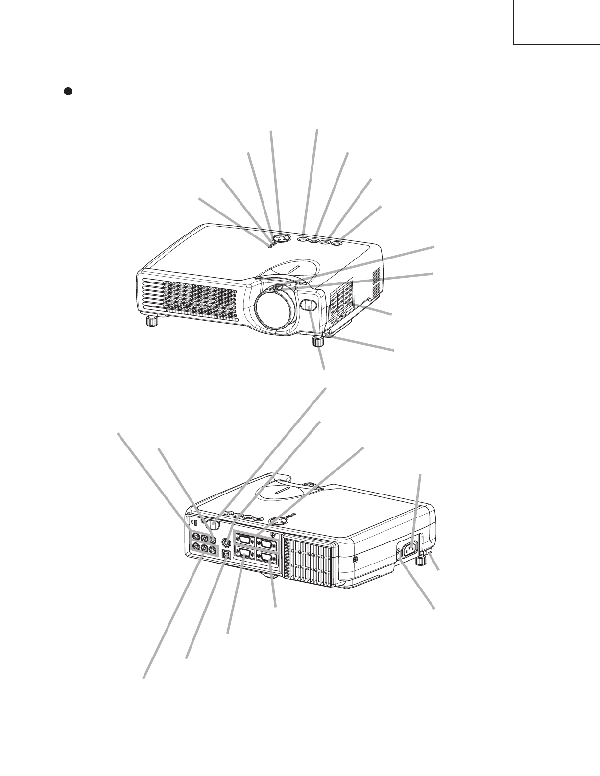
3. Names of each part
Zoom ring
Focus ring
Air filter
Elevator button
Elevator button
KEYSTONE button
STANDBY/ON button
INPUT button
RESET button
MENU button
LAMP LED
TEMP LED
POWER LED
Remote sensor
AC power inlet
S-VIDEO IN port
RGB IN 1 and 2 ports
AUDIO IN R and L ports
VIDEO IN port
CONTROL port
RGB OUT port
USB port
COMPONENT VIDEO port
Power switch
Parts names
CP-S317
CP-X327
ET
S
E
R
E
N
TO
R
E
W
P
N
E
T
P
N
A
L
S
EY
O
P
K
UT
P
IN
N
/O
Y
B
D
TAN
S
S
TAN
D
B
Y
/O
N
IN
P
U
T
K
E
Y
S
T
O
N
T
E
P
O
E
W
E
R
R
E
S
E
T
L
A
N
P
N
P
3
Page 4
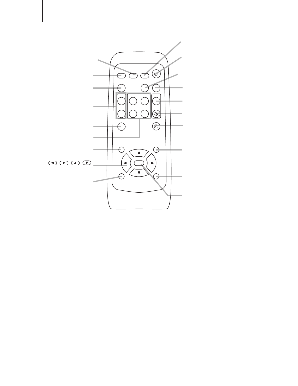
CP-S317
STANDBY/ON button
VIDEO button
MENU button
RGB button
BLANK button
SEARCH button
VOLUME button
MUTE button
KEYSTONE button
ASPECT button
AUTO button
MAGNIFY button
KEYBOARD buttons
FREEZE button
POSITION button
ESC button
,,,
Cursor buttons
RESET button
ENTER button
CP-X327
VIDEO
RGB SEARCH
ASPECT
HOME
MAGNIFY
ON
END
OFF
ENTER
ESC RESET
STANDBY/ON
AUTO BLANK
PAGE UP VOLUME
PAGE DOWN
MUTE
KEYSTONEFREEZE
MENUPOSITION
Remote control transmitter
4
Page 5
4. Adjustment
4-1 Before adjusting
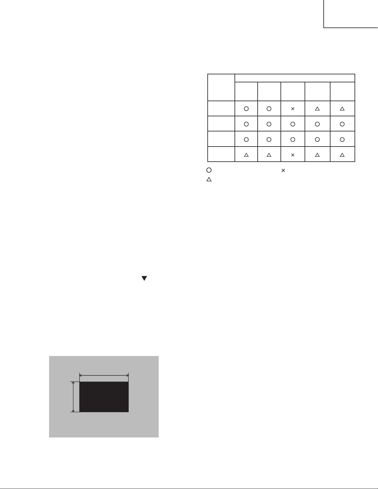
4-1-1 Selection of adjustment
When any parts in the table 4-1 are changed, choose
the proffer adjusting items with the chart.
CP-S317
CP-X327
Table 4-1: Relation between the replaced part and adjustment
Adjustment
Replaced
part
Dichroic
optics unit
LCD/LENS
prism
assembly
PWB
assembly
drive
Lamp
unit
assembly
:
means need for adjustment.
:
means recommended.
Ghost
(Chap.4-2)
Flicker
(Chap.4-3)
PSIG/NRSH
(Chap.4-4)
:
means not need for adjustment.
White
balance
(Chap.4-5)
Color
uniformity
(Chap.4-6)
4-1-2 Setting of condition before adjustment
1. Before starting adjustment, warm up the projector
for about 10 minutes.(Blank white)
2. Set Zoom Wide to Max. And project an image with
more than 40 inches in diagonal size.
3. Normalizing the video adjustment.
(Press the [MENU] button of the Remote control
transmitter to display the MAIN menu, and then press
the [RESET] button. And select the [DEFAULT]. Next,
open MAIN menu and press the [ ] key to display
the PICTURE1 menu, then press the [RESET] key to
set to [DEFAULT].)
*note :The MAIN and PICTURE1 menu is not reset
with no signal.
4-2 Ghost adjustment
Signals for internal adjustment
30%
30%
0/255
112/255
4. Set the normal at OPT-WHISPER in the menu.
5. Reset KEYSTONE correction.
6. Perform all adjustments from the Adjustment menu.
Perform the following operations to display the
Adjustment menu.
a. Press the [MENU] button of the Remote control
transmitter (the Setup menu will appear).
b. Next, press the [RESET] button one time. And
press the [RESET] button again for 5 seconds
or more (the Adjustment menu will appear).
Adjustment procedure
1. Use DAC-P - GHOST - R: in the Adjustment menu
to adjust so that R color ghost is at a minimum.
(Set the adjustment value to default, and then raise the
value. When a ghost appears to the left of a vertical
line, reduce the value by 2 steps. :CP-S317 only)
2. In the same way, use DAC-P - GHOST-G: in the
Adjustment menu to adjust so that G color ghost is
at a minimum.
3. In the same way, use DAC-P - GHOST-B: in the
Adjustment menu to adjust so that B color ghost is
at a minimum.
5
Page 6
CP-S317
CP-X327
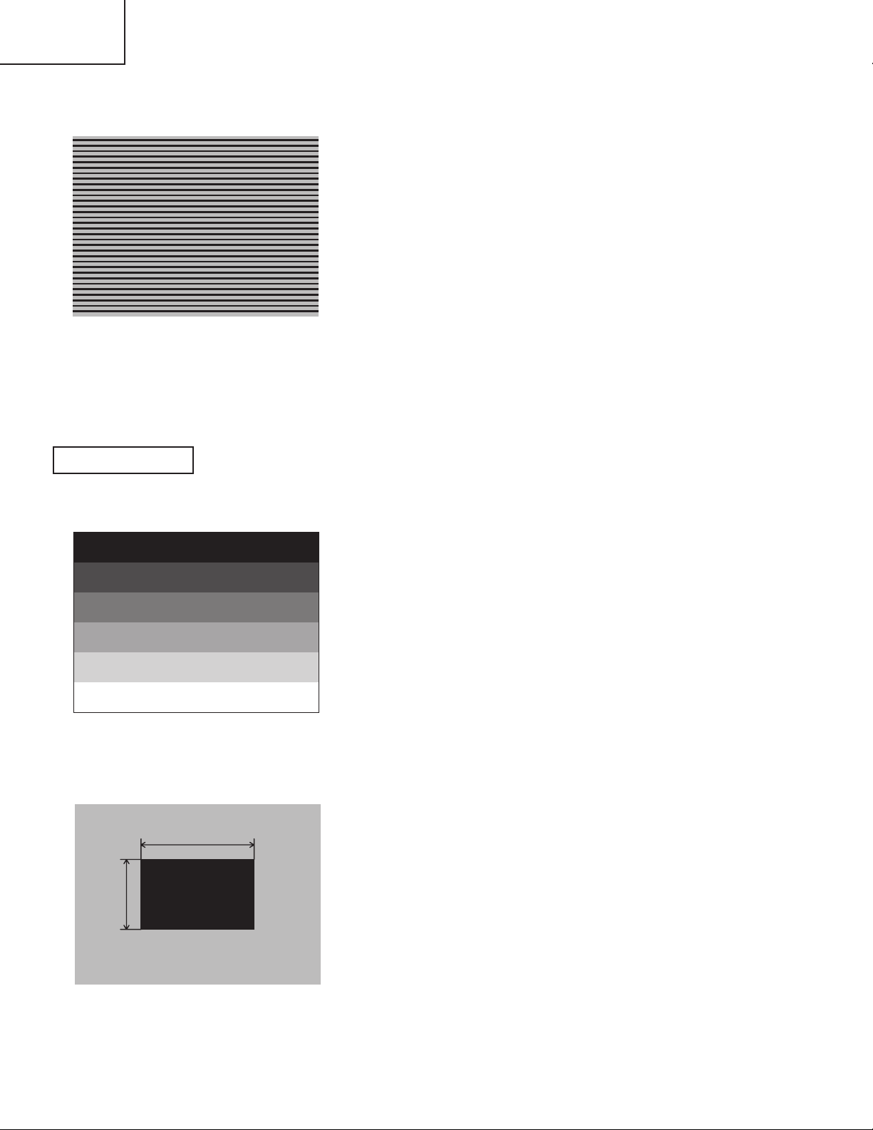
4-3 Flicker adjustment
Signals for internal adjustment
(V.COM adjustment)
CP-S317 ONLY
4-4
PSIG-G adjustment
Signals for internal adjustment
(vertical stripe adjustment)
192/255
160/255
128/255
96/255
Adjustment procedure
1. Make this adjustment after completing the
adjustment in 4-2 Ghost adjustment.
2. Use DAC-P - V.COM - R: in the Adjustment menu
to adjust so that the flicker at the center of the
screen is less than the flicker at the periphery.
(When the flicker is about the same across the
whole screen, adjust so that the flicker at the
center of the screen is somewhat less than
elsewhere.)
3. In the same way, use DAC-P - V.COM-G: in the
Adjustment menu to adjust the G color flicker.
4. In the same way, use DAC-P - V.COM-B: in the
Adjustment menu to adjust the B color flicker.
Adjustment procedure
1. Make this adjustment after completing the
adjustment in 4-3 Flicker adjustment.
2. Use DAC-P - PSIG - G: in the Adjustment menu to
adjust so that the vertical lines spaced every 6 or
12 dots are as inconspicuous as possible.
64/255
32/255
4-4-1
Signals for internal adjustment
PSIG-B adjustment
30%
(vertical streaks adjustment)
30%
0/255
112/255
Adjustment procedure
1. Make this adjustment after completing the
adjustment in 4-3 Flicker adjustment.
2. Use DAC-P - PSIG - B: in the Adjustment menu to
adjust so that the vertical streaks on the upper of
window pattern.
6
Page 7

CP-X327 ONLY
4-4
NRSH adjustment (vertical stripe adjustment)
Signals for internal adjustment
192
168
144
120
96
72
48
24
/255
/255
/255
/255
/255
/255
/255
/255
CP-S317
CP-X327
Adjustment procedure
1. Make this adjustment after completing the
adjustment in 4-3 Flicker adjustment.
2. Use DAC-P - NRSH - R: in the Adjustment menu to
adjust so that the vertical lines spaced every 6
dots are as inconspicuous as possible.
(Reduce the adjustment value when black stripes
appear in the 2nd or 3rd tone from the black side.
Note that when the adjustment value is lowered,
white stripes may appear in the 2nd or 3rd tone
from the bright side. Should this happen, adjust so
that the stripes are as inconspicuous as possible.)
3. In the same way, use DAC-P - NRSH - G: in the
Adjustment menu to adjust vertical stripes of G color.
4. In the same way, use DAC-P - NRSH - B: in the
Adjustment menu to adjust vertical stripes of B color.
4-5
White balance adjustment (visual inspection)
Preparations
1. Perform these adjustments after the PSIG
adjustment described in Section 4-4.
Adjustment procedure
1. First, adjust the G color.
2. Select GAMMA, SUB-CONTRAST, and G: in the
Adjust menu. If the background is white solid,
press the [MENU SELECT] key on the Remote
control transmitter to change to [G] monochrome in
the 28-tone grayscale.
3. Adjust GAMMA, SUB-CONTRAST, and G: in the
Adjust menu so that brightness of 28 steps is best.
4. Don’t adjust GAMMA, SUB-BRIGHT, and G: in the
Adjust menu. Because we want to keep the best
contrast ratio.
5. Then adjust colors R and B.
2. Reset gamma correction before adjustment.
Place the cursor on [GAMMA] in the Adjustment
menu, press the [RESET] key and select
[DEFAULT].
6. Select GAMMA, SUB-CONTRAST, and G: in the
Adjust menu. If the background is white solid,
press the [MENU SELECT] key on the Remote
control trasmitter to change to [W] monochrome in
the 28-tone grayscale.
7. Adjust GAMMA, SUB-BRIGHT, R: and B: in the
Adjust menu so that low-brigtness white balance is
best.
8. Adjust GAMMA, SUB-CONTRAST, R: and B: in
the Adjust menu so that middle-brightness white
balance is best.
9. Repeat steps 7 to 8 above, and adjust so that
brightness white balance of 28 steps is best.
7
Page 8
CP-S317
CP-X327
4-6 Color uniformity adjustment
Preparations
1. Perform these adjustments after the white balance
adjustment described in Section 4-5.
2. Make a color uniformity adjustment for the
following four tones.
MIN tone (approx. 4% input signal)
MID-L tone (approx. 14% input signal)
MID-H tone (approx. 25% input signal)
MAX tone (approx. 57% input signal)
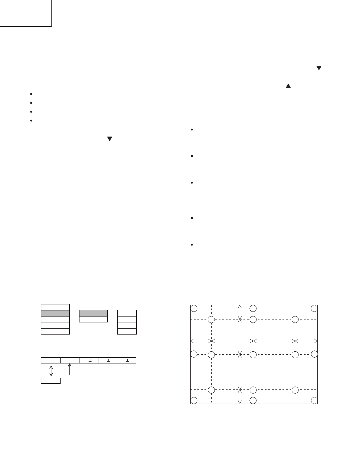
3. Place the cursor on the tone to be adjusted in the
Adjust menu and press the [ ] key. This displays
the Adjust Tone menu at the bottom of the screen.
Select the major adjustment lattice point No. and
color, and then adjust them.
4. The major adjustment lattice point numbers (a total
of 17 points) corresponds to the major adjustment
lattice point positions in the diagram on the right.
The color uniformity of the entire screen can be
adjusted by adjusting the white balance for each of
the points starting in order from the low numbers.
5. Adjustment point No.1 should not be adjusted,
because it controls the brightness of the entire
screen.
6. To temporarily turn correction off, place the cursor
on “ON” in the Adjust Tone menu and press the [ ]
key. To turn it on again, place the cursor on OFF in
the Adjust Tone menu and press the [ ] key.
7. Although this adjustment can also be made using
internal signals, we will here use the [MENU
SELECT] key on the Remote control transmitter to
select the following two signals.
Solid monochrome adjustment color (use G color
adjustment when a color differential meter is
used).
Solid white (use for adjustment other than
above).
8. Reset color-shading correction before adjustment.
When 4 tones and all colors are to be reset,
place the cursor on [C.UNIF.] in the Adjustment
menu, press the [RESET] key and select
[DEFAULT].
When only 1 tone is to be reset, place the cursor
on the tone to be reset, press the [RESET] key
and select [DEFAULT].
Single tone and monochrome resets cannot be
performed.
Adjust menu
VID-AD
C. UNIF.
DAC-P
GAMMA
Adjust Tone menu
No. 1 R 0
ON
OFF
Major adjustment lattice point No.
LEVEL
BLACK
MIN
MID-L
MID-H
MAXSTRIPE
G 0 B 0
Major adjustment lattice point position
14 12
6 4 8
H/6 H/3 H/3 H/6
10 11
15 17
2 1 3
7 5 9
V/6
V/3
V/3
V/6
13
16
8
Page 9

Adjustment procedure 1
(when a color differential meter is used)
1. First adjust [MID-L] tone [G:].
2. Select adjustment point [No.2][G:].
When the background is not [G] monochrome,
press the [MENU SELECT] key on the Remote
control transmitter to change to solid [G]
monochrome.
3. Measure the illumination at adjustment points No.
2, No.3, No.10 and No.11.
The values should be:
No.2 = Y2 [lx] No.10 = Y10 [lx]
No.3 = Y3 [lx] No.11 = Y11 [lx]
4. No.2 and No.3 adjustment point have the average
of Y2 and Y3.
Y2 = ( Y2 + Y3 ) / 2 ± 2 [%]
Y3 = ( Y2 + Y3 ) / 2 ± 2 [%]
5. No.10 and No.11 adjustment point have the
average of Y10 and Y11.
Y10 = ( Y10 + Y11 ) / 2 ± 2 [%]
Y11 = ( Y10 + Y11 ) / 2 ± 2 [%]
6. Then adjust [MID-L] tone [R] and [B].
When the background is [G] monochrome, press
the [MENU SELECT] key on the Remote control
transmitter to change to solid white.
7. Measure the color coordinates of adjustment point
[No.1] and make a note of them.
Assume that they are x = x1, y = y1.
Note: When the CL-100 color and color difference
meter is used, the [
convenient. When adjustment point [No.1]
color coordinate has been selected, set the
slide switch on the side to [ ](delta) while
holding down the [F] button on the front
panel. The measurement shown after this
displays the deviation from measurement
point 1.
8. Measure the color coordinates of measurement
point [No.2] and adjust [No.2][R:] and [B:] so that
the coordinates are as follows.
x = x1 ± 0.005 , y = y1 ± 0.010
](delta) mode is
CP-S317
CP-X327
9. Similarly, measure adjustment points [No.3] to
[No.17] and adjust their color coordinates starting
in order from the small number points.
This completes adjustments required for [MIN].
Note: Since excessive correction may lead to a
correction data overview during internal
calculations, use the following values for
reference.
[No.2] to [No.5] ± 40 or less
[No.6] to [No.9] ± 50 or less
[No.10] to [No.13] ± 70 or less
[No.14] to [No.17] ± 120 or less
10. Then adjust [MIN] tone [G] so that the adjustment
data set two times as much as [MID-L] tone [G].
This completes [G] color adjustments.
11. Then adjust [MIN] tone [R] and [B].
Select [No.2] [B:] and press the [MENU SELECT]
key on the Remote control transmitter to change to
solid white.
12. Measure the color coordinates of adjustment point
[No.1] and make a note of them.
Assume that they are x = x1, y = y1.
13. Now measure the color coordinates of
measurement point [No.2] and adjust [No.2][R:]
and [B:] so that the coordinates are as follows.
x = x1 ± 0.005 , y = y1 ± 0.010 (Target)
x = x1 ± 0.020 , y = y1 ± 0.040
14. Similarly, measure adjustment points [No.3] to
[No.17] and adjust their color coordinates starting
in order from the small number points.
This completes [MIN] tone adjustments.
15. Now make similar adjustments for [MID-H] tone.
(Adjust [MID-H] tone [G] so that the adjustment
data set half as many as [MID-L] tone [G].)
16. Now make similar adjustments for [MAX] tone.
(Adjust [MAX] tone [G] so that the adjustment data
set half as many as [MID-L] tone [G].)
9
Page 10

CP-S317
CP-X327
Adjustment procedure 2
(visual inspection)
1. First adjust [MIN] tone [G:].
2. Select [No.2] [G:].
If the background is [G] monochrome, press the
[MENU SELECT] key on the Remote control
transmitter to change to solid white.
3. View measurement point [No.2] and [No.3].
Lower the [G] color intensity only of the color point
whose [G] color is more intense than measurement
point [No.1].
4. View measurement point [No.10] and [No.11].
Lower the [G] color intensity only of the color point
whose [G] color is more intense than measurement
point [No.1], and raise the intensity of the point
whose color intensity is lower than measurement
point [No.1].
5. Now adjust the [MIN] tone for colors [R] and [B].
6. View measurement points [No.2], [No.3], [No.10]
and [No.11]. Adjust the [R] and [B] of each
measurement point so that they have the same
color as measurement point [No.1].
Adjustment technique:
First, adjust [B:] of the point whose color is to be
adjusted so that it approximates that of [No.1]. If
[R:] is low at this time, the image will have cyan
cast, in which case [R:] is increased. On the other
hand, if [R:] is excessive, the image will have a
magenta cast, in which case [R:] is decreased.
Overall, a cyan cast makes it easy to see color shading.
7. Next, view measurement points [No.4], [No.5],
[No.12], [No.13] and make similar adjustments.
8.
Then adjust measurement points [No.6], [No.7], [No.8],
[No.9], [No.14], [No.15], [No.16] and [No.17].
This completes the [MIN] tone adjustments.
9. Make similar another three tones as described in
steps 1 to 8 above.
10
Page 11
CP-S317
CP-X327
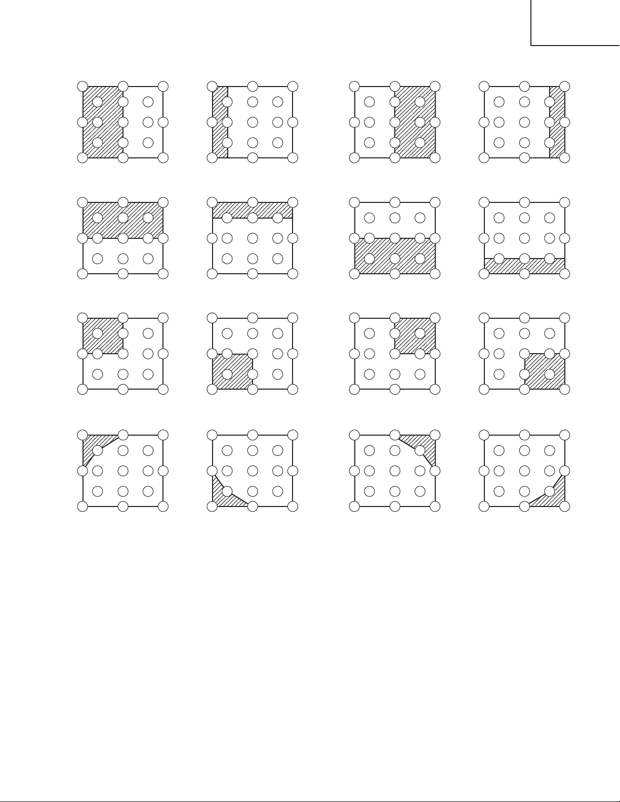
No. 2 deviation range No. 10 deviation range No. 3 deviation range No. 11 deviation range
14
10
15 13
No. 4 deviation range No. 12 deviation range No. 5 deviation range No. 13 deviation range
15 13
No. 6 deviation range No. 7 deviation range No. 8 deviation range No. 9 deviation range
12
6
4
2
1
5
7
5
7
16
8
3
11
9
17
1614 12
86 4 84
9
17
1614 12
86 4 84
14 12
6
10
2
7
15 13
6
10 1
2
7
15 13
6
16
8
4
3
1
5
5
11
9
17
1614 12
3
11
9
17
1614 12
14
10
15
14
10 1
15
14
12
6
4
2
1
5
7
13
12
6
4
5
7
13
12
6
4
16
8
3
11
9
17
16
8
3 112
9
17
16
8
14 12
4
6
10
15 13
14 12
10
15 13
14 12
1
2
7
4
6
1
2
7
46
8
3
5
9
8
3
9
5
8
16
11
17
16
113 11210 1
17
16
3
3 11210 1
9
5
7
15 13
No. 14 deviation range No. 15 deviation range No. 16 deviation range No. 17 deviation range
6
10
5
7
15 13
17
1614 12
84 84
3 112 1
9
17
10 12
10 12
15
5
7
1315
6
5
7
13
11
9
17
1614 12
3
11
9
17
10
7
15
14
6
10
7
15
1
13
12
4
1
13
3 112
9
5
17
16
8
32
11
9
5
17
10
15
14 12
10
15
2
7
2
7
1 3 11
46
1 3511
13
95
5
8
9
5
1713
16
17
11
Page 12
CP-S317
CP-X327
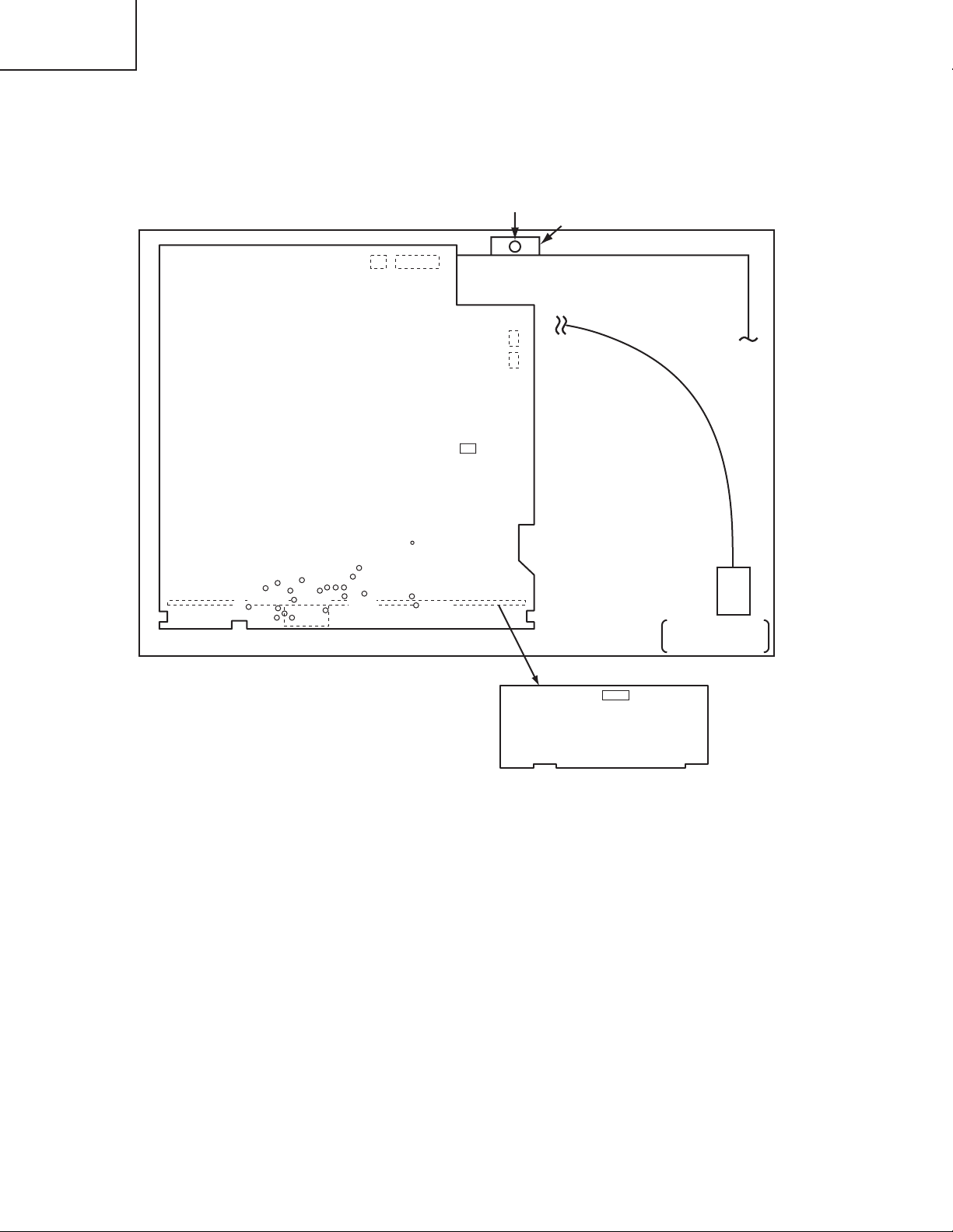
5. Troubleshooting
Check points at trouble shooting
12141
E302 E800
E805
E807
TH950
PWB assembly SENSOR
1
4
1
2
PWB assembly Drive
TP04
TP03
TP05
TP06
TP110
TP105
35
TP101
TP116
TP114
36
TP115
E101
TP01
TP02
1
TP104
70
TP1H
TP108
TP109
TP103
TP118
TP106
CHJ17
TP117
TP102
1
I256
1120
10
TSW
TEMPERATURE
SENSOR
IS01
PWB assembly Signal
12
Page 13
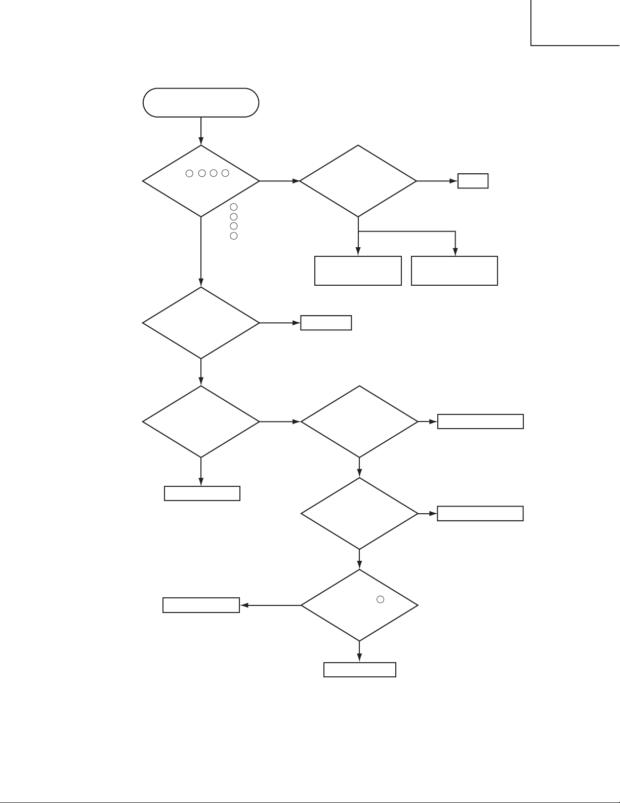
Power can not be turned on
Are
voltage input
at pins , , , of
E800 on the PWB assembly
Drive at standby
3
2
mode?
4 5
YES
: +14V
2
: +17V
3
: +6V
4
: +4.3V
5
NO
Disconnect
TSW form Power unit
(circuit). And check
TSW short or
open?
Short
Open
CP-S317
CP-X327
TSW
What is the state of
TEMP indicator?
Not light
What is the state of
LAMP indicator?
Not light
PWB assembly Drive
Blinks
Blinks
Power unit (circuit)
DC Fan
Is the LAMP COVER
set?
OK
Is the LAMP
connection?
OK
Fuse
on Power unit (circuit)
NG
Set the LAMP COVER
NG
Set the LAMP again
PWB assembly Drive
H (More than 6V)
Measure
voltage at the of
E807 on the PWB
assembly drive.
PWB assembly SW
2
L (OV)
13
Page 14
CP-S317
CP-X327
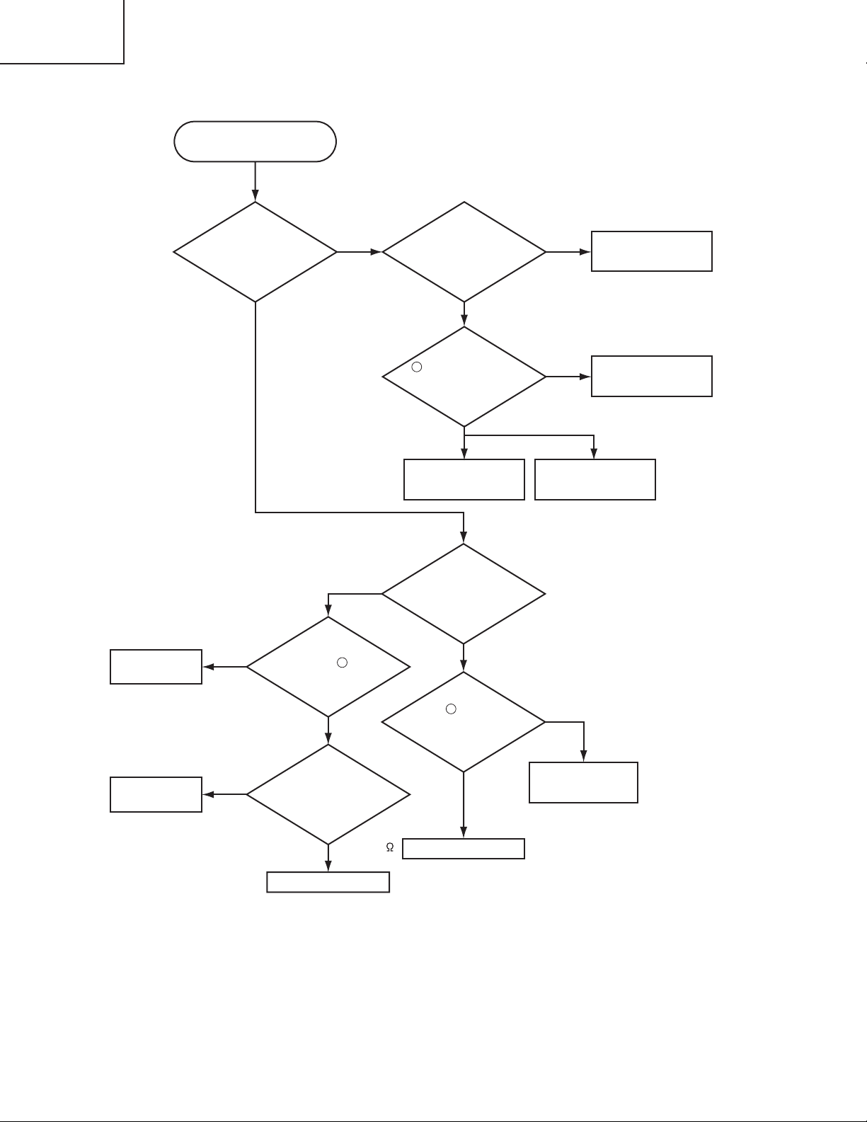
Lamp does not light
DC FAN
(INTAKE A/B)
PWB assembly
SENSOR
What is the state of
LAMP indicator
during operation?
Not light
H (3.3V)
Infinity
Measure sure
voltage at the of I256
on the PWB assembly
the resisitance of
TH950 on the PWB
assembly SENSOR at
disconnecting
Light
2
Drive.
L (OV)
Measure
E302.
about 10k
Blinks
Change the lamp.
Does lamp light?
Not light
Is the
voltage at the
1
of E805 on the PWB
assembly Drive fixed to "L"
during warming-up?
"L" = 0V
NO
Power unit (ballast)
What is the state of
TEMP indicator?
Not light
Is the voltage
3
at the of E805 on
the PWB assembly Drive
set to "L" during
warming-up?
YES
Power unit (ballast)
Light
YES
Power unit (circuit)
"L" = 0V
PWB assembly Drive
PWB assembly Drive
NO
Lamp
14
PWB assembly Drive
Page 15
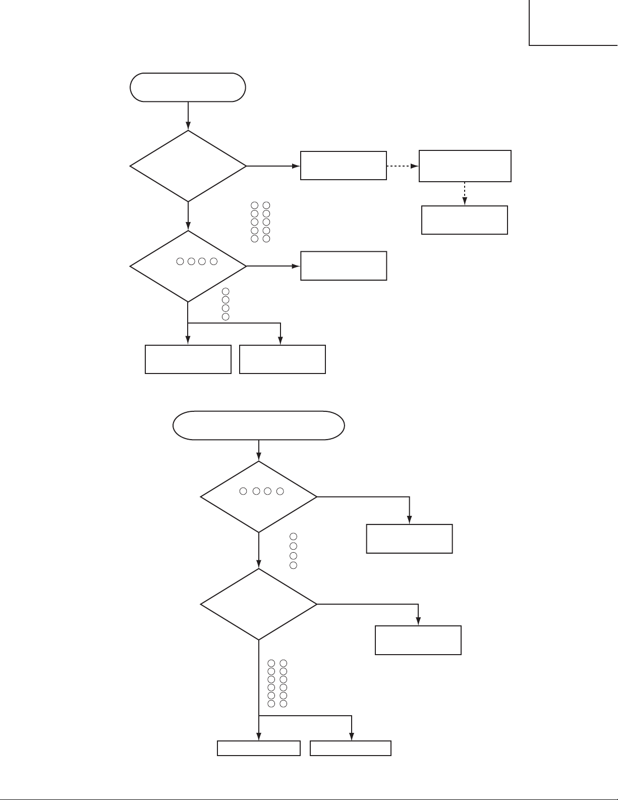
Picture is not displayed only
when the RGB signal is input
Check at operating mode
Are
signal input
at each pin of E101 on
the PWB assembly
Drive?
(TP06) , : R signal
YES
(TP02) , : G signal
(TP04) , : B signal
(TP106) , : H sync
Are
(CHJ17) , : V sync
voltage input
at pins , , , of
2 3 4 5
E800 on the PWB
assembly
Drive?
YES
2
3
4
5
: +14V
: +17V
:+6V
:+4.3V
NO
5 66
3 68
1 70
8
7 64
NO
CP-S317
CP-X327
Change the IS01 on the
PWB assembly Signal
63
Power unit
(circuit)
PWB assembly Signal.
It is repaired ?
YES
IC (IS01)
EL4332CS
PWB assembly Drive
Picture is not displayed only when the
VIDEO, S-VIDEO, Component Signal is input
LCD panel
Check at operating mode
Are
voltage input at
2 3 4
pins , , , of
5
E800 on the PWB
assembly
Drive?
YES
Are signal
input at these
pins of E101 on the
PWB assembly
Drive?
YES
2
: +14V
3
: +17V
4
: +6V
5
: +4.3V
NO
Power unit (circuit)
NO
PWB assembly Signal
22 49
, VIDEO (Composit) (TP112)
26 45
, S-VIDEO (Y) (TP110)
24
47
, S-VIDEO (C) (TP111)
35
36
, Component (Y) (TP01)
33
38
, Component (Cb) (TP03)
31
40
, Component (Cr) (TP05)
PWB assembly Drive
LCD module assembly
15
Page 16
CP-S317
CP-X327
No sound
Check at operating mode
Are the
signals input
at each pin of E101
on the PWB assembly
Drive?
NO
YES
56
(TP117) : MUTE (0V)
17
(TP104) : CLK-VOLUME Control
54
(TP115) : DATA-VOLUME Control
57
(TP118) : POWER-AUDIO (+3.3V)
Speaker
Can not operate to Mouse
At the time
of remote control
operation. Are the signals puls
at pins 13 of E101 (RMT) on
the PWB assembly
Drive ?
YES
NO
PWB assembly Drive
PWB assembly Signal
PWB assembly Drive
Power unit (circuit)
The check after PWB change
1. PC power supply OFF
2. Connection of cable
3. Projector starting
4. PC starting
*When not operating :
PC set up change of cable.
16
PWB assembly Input
Can not control to RS-232C
Are the
signals data at pins
52
of E101 (TP114:RD) on
the PWB assembly
Drive ?
NO NO
PWB assembly Input
YES
Are the
signals data at pins
19
of E101 (TP105:TD) on
the PWB assembly
Drive ?
PWB assembly Drive
The check after PWB change
1. PC power supply OFF
2. Connection of cable
3. Projector starting
4. PC starting
*When not operating :
PC set up change of cable.
Page 17
CP-S317
CP-X327
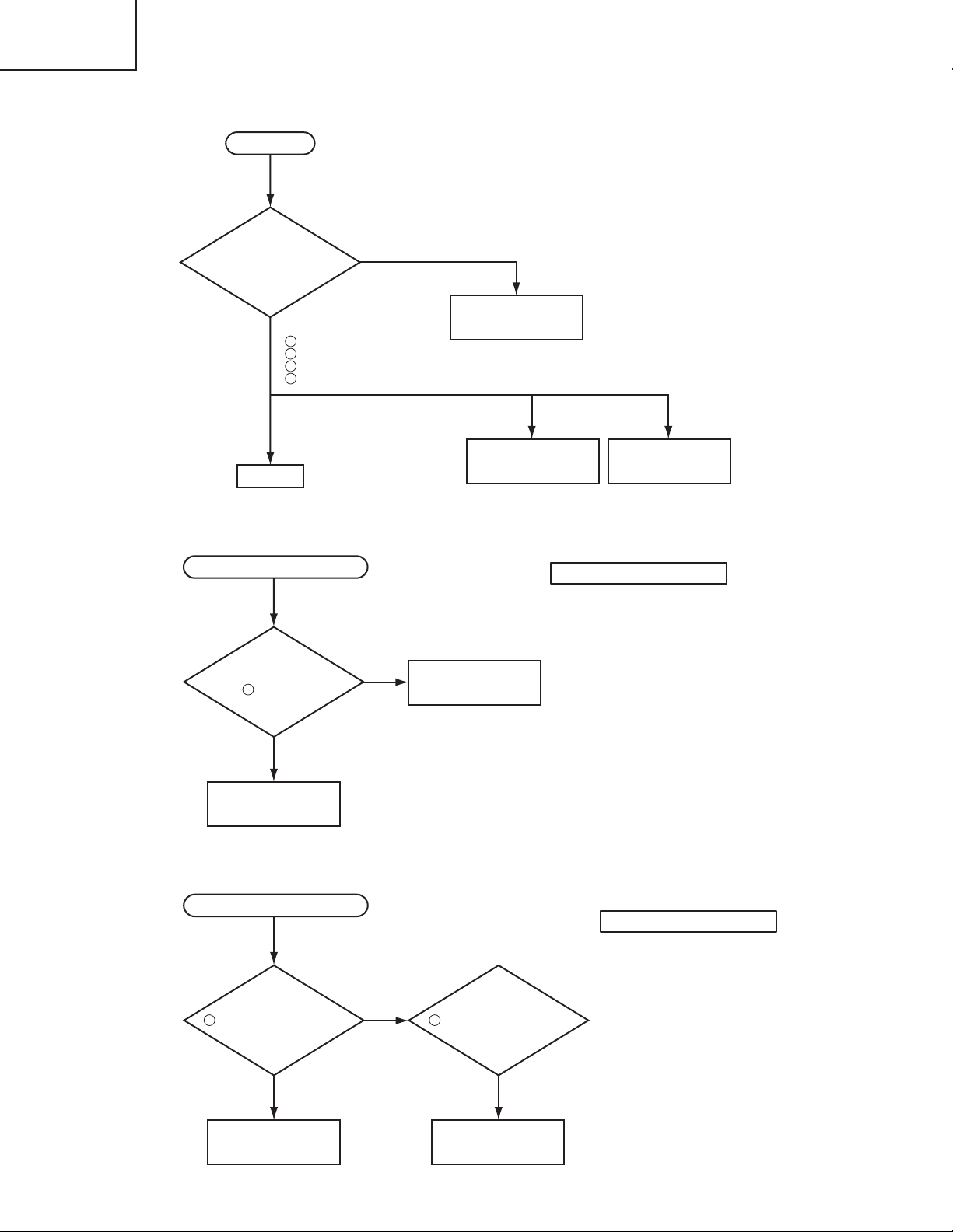
6. Service points
Cautions when removing the PWB assembly Drive
When removing the PWB assembly Drive, there is danger of damaging the connector connecting cables and the
PWB assembly Signal.
1) Disconnect 6 cables and remove 3 screws.
PWB assembly Drive
Disconnect 6 cables
2) Lift up the rearward of the PWB assembly Drive to the front.
FRONT
PWB assembly Drive
3) Disconnect 5 cables lifting the PWB assembly Drive.
Disconnect 5 cables
Remove 3 screws
Lift up
Disconnect the board-to-board connector.
REAR
Cautions when removing the POWER UNIT (BALLAST)
When removing the cable (CNBAR) connected to POWER UNIT (BALLAST) there is danger of damaging the small
PWB connecting cables.
219'470+6$#..#56
J1
Disconnect the CNBAR from connector J2,
CNBAR
while pressing the sub-board (to prevent the
J2
stress on the sub-board).
17
Page 18
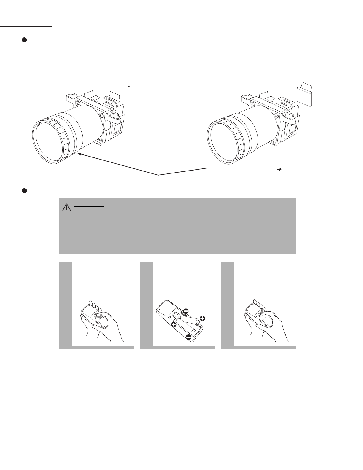
CP-S317
1
Remove the battery
cover
Slide back and remove
the battery cover in the
direction of the arrow.
Insert the batteries
Align and insert the two AA
batteries (that came with the
projector) according to their plus
and minus terminals (as indicated
in the remote control).
Close the battery
cover
Replace the battery cover
in the direction of the arrow
and snap it back into place.
2 3
CAUTION
Precautions to observe in regards to the batteries
Always handle the batteries with care and use them only as directed. Improper use may result in
battery cracking or leakage, which could result in fire, injury and/or pollution of the surrounding environment.
• Keep the battery away from children and pets.
•
Be sure to use only the batteries specified for use with the remote control. Do not mix new batteries with used ones.
•
When inserting batteries, verify that the plus and minus terminals are aligned correctly (as indicated in the remote control).
• When you dispose the battery, you should obey the law in the relative area or country.
CP-X327
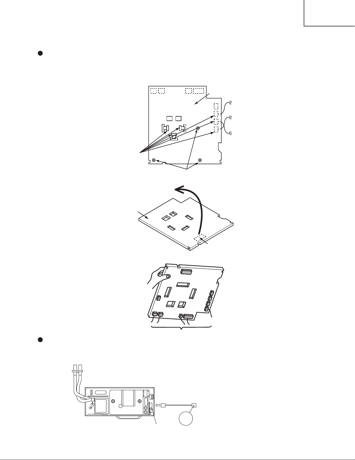
Before Replacing the LCD / Lens Prism
You should not replace separately the parts of the liquid crystal LCD / Lens Prism because it works properly only
when used together. Therefore, regarding these parts, you can either replace part , LCD / Lens Prism assembly, or
send the whole unit LCD / Lens Prism assembly back to Hitachi, where we will replace the malfunctioning part,
recondition the device and send it back to you.
DISTRIBUTOR HITACHI
Do not disassemble the unit
because replacement of separate
parts is not possible.
Return
Replacement of G Panel Reconditioning
G Panel
Using the Rremote control
18
Page 19
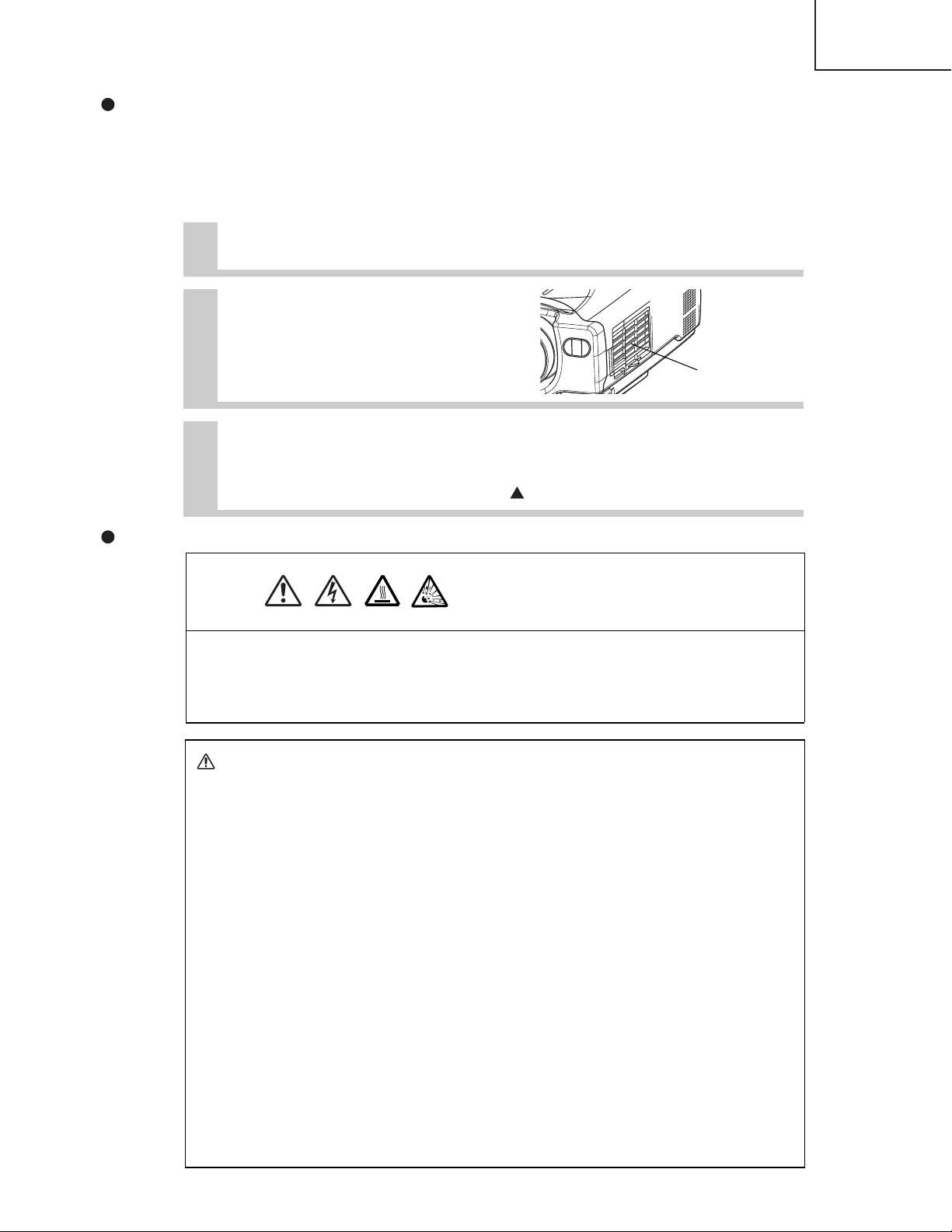
Caring for the air filter
HIGH VOLTAGE
HIGH TEMPERATURE
HIGH PRESSURE
Before replacing the lamp, check the serial number of the replacement lamp bulb (sold separately:
DT00511 for CP-S317/DT00521 for CP-X327), then contact your local dealer. Before replacing the
lamp, turn off the power, and unplug the power cord, then wait at least 45 minutes, in order to
ensure that the lamp is properly cooled. Removing the lamp bulb while it is still hot could cause
burns, or cause the lamp bulb to burst.
The LCD projector uses a glass lamp bulb. It is a mercury lamp with high
internal pressure. High-pressure mercury lamps can break with a loud
bang, or burn out, if jolted or scratched, or through wear over time. Each lamp has a
different lifetime, and some may burst or burn out soon after you start using them. In
addition, when the bulb bursts, it is possible for shards of glass to fly into the lamp housing,
and for gas containing mercury to escape from the projector’s vent holes.
•
Handle with care: jolting or scratching could cause the lamp bulb to burst during use.
•
If the replace lamp indicator (see "Related Messages" and "Regarding the
indicator Lamps") comes on, replace the lamp as soon as possible. Using the
lamp for long periods of time, or past the replacement date, could cause it to burst. Do
not use old (used) lamps; this is a cause of breakage.
•
If the lamp breaks soon after the first time it is used, it is possible that there are electrical problems
elsewhere besides the lamp. If this happens, contact your local dealer.
•
If the lamp should break (it will make a loud bang when it does), ventilate the room well, and make
sure not to breathe the gas that comes out of the projector vents, or get it in your eyes or mouth.
•
If the lamp should break (it will make a loud bang when it does), unplug the power cord from
the outlet, and make sure to request a replacement lamp from your local dealer. Note that
shards of glass could damage the projector’s internals, or cause injury during handling, so
please do not try to clean the projector or replace the lamp yourself.
•
Obey local ordinances when disposing of used lamps. In most cases, it is possible to dispose of used
bulbs in the same manner as used glass bottles, but in some cases, bulbs are sorted separately.
• Do not use the projector with the lamp cover removed.
WARNING
The air filter should be cleaned about every 100 hours. If the LAMP indicator and
TEMP indicator blink red simultaneously, or a message prompts you to clean the air
filter when you turn on the unit, the filter needs to be cleaned. (See "Related
Messages" and "Regarding the Indicator Lamps" for details.)
1
Turn off the projector, and unplug the power cord
2
Apply a vacuum cleaner to
the top of the air filter cover
to clean the air filter
3
Turn on the projector, and use the menu to reset the filter
timer
• To reset the air filter timer, from the OPTION menu, select FILTER TIME.
Air Filter Cover
CP-S317
CP-X327
(Select RESET on the menu with the button.)
Lamp (
Option Lamp: DT00511(CP-S317) / DT00521(CP-X327))
19
Page 20

CP-S317
• The LAMP indicator is also red when the lamp unit reaches high temperature.
Before replacing the lamp, switch power OFF, wait approximately 20 minutes, and switch power
ON again. If the LAMP indicator is still red, replace the lamp.
NOTE
All projector lamps will wear out eventually. If used for long periods of time, the image could become
darkened, and the color contrast could be impacted as well. We recommend that you replace your lamps
early. If the LAMP indicator turns red, or a message prompts you to replace the lamp when you power up
the projector, the lamp needs to be replaced. (See "Related Messages" and "Regarding the
Indicator Lamps" for details.)
1
Turn off the projector, and unplug the
power cord. Allow the lamp bulb to cool
for at least 45 minutes, and prepare a
new lamp (sold separately: DT00511 for
CP-S317/DT00521 for CP-X327)
5
Insert the new lamp, and tighten the 1
screw firmly to lock it in place
•
Also steadily push the opposite side of the
screwed side of the
lamp into the unit.
6
Replace the lamp cover, and tighten
the 2 screws firmly to lock it in
place
7
Slowly turn the projector so that
the top is facing up
2
After making sure that the projector has
cooled adequately, slowly flip over the
projector, so that the bottom is facing up
3
Unscrew the 2
screws, and
remove the
lamp cover
4
Unscrew the 1 screw, and slowly pull
out the lamp by the handle
•
Be careful not to touch the inside of the lamp case.
ATTENTION •
Make sure that the screws are screwed in firmly. Loose screws could result in damage or injury.
• Do not use with lamp cover removed.
•
Do not reset the lamp timer without replacing the lamp. Reset the lamp timer always when replacing
the lamp. The message functions will not operate properly if the lamp timer is not reset correctly.
• When the lamp has been replaced after the message of "CHANGE THE LAMP ...THE POWER
WILL TURN OFF AFTER 0 hr." is displayed, or the LAMP indicator is red, complete the following
operation within 10 minutes of switching power ON.
8
Turn on the projector power, and using
the menu, reset the lamp timer
•
To reset the lamp timer, from the OPTION
menu, select LAMP TIME.
CP-X327
Replacing the Lamp
20
Page 21

CP-S317
CP-X327
Resetting the Lamp Timer
Reset the lamp timer after replacing the lamp. When the lamp has been replaced after the LAMP indicator is red, or
the CHANGE THE LAMP message is displayed, complete the following operation within ten minutes of switching
power ON. The power will be turned off automatically in over 10 minutes.
1. Switch power ON, and select the LAMP TIME on the OPTION menu.
2. Depress the RESET button for at least 3 seconds while lamp time is being displayed.
The reset menu will then appear.
3. Select RESET on the menu with the
NOTE:
Do not reset the lamp timer without replacing the lamp. Reset the lamp timer always when replacing the lamp. The
message functions will not operate properly if the lamp timer is not reset correctly.
button, and wait until the timer display is cleared.
STANDBY/ON
RGB SEARCH
VIDEO
ASPECT
AUTO BLANK
HOME
MAGNIFY
OFF
S
TAN
D
B
Y
/O
N
IN
P
U
2
1, 3
L
T
A
N
P
K
T
E
E
Y
N
S
T
P
O
P
N
O
E
W
E
R
R
E
S
E
T
3
ESC RESET
PAGE UP VOLUME
ON
END
PAGE DOWN
MUTE
KEYSTONEFREEZE
MENUPOSITION
ENTER
1
2
1
21
Page 22

CP-S317
CP-X327
Notice of AUTO adjustment
Use of AUTO adjustment with the image through RGB input optimizes VPOSI, HPOSI, HSIZE and HPHASE
automatically.
In case that projected image has dark tone around its peripheral, AUTO operation sometimes makes artifacts in the
image, shifts capture area and so on. Those failures are caused by period of image data is not exactly
distinguished to period of blanking on signal processing.
To avoid such phenomena, AUTO function should be used with the full size picture that has bright tone on its
peripheral.
Image when AUTO operates correctly
Note
1) The phenomenon at the failure of AUTO adjustment depends on resolution of input source, scene of picture etc.
2) There is no failure above in AUTO with video source through VIDEO, S-VIDEO or COMPONENT input. The reason
is why recognition of input signal’s standard does not need to search the capture range from input signal itself.
Image when AUTO fails.
Noting image of top or bottom lines.
Shift of the image to East or West.
Artifacts on image. Etc.
22
Page 23

CP-S317
CP-X327
PIN LOCK System
If the following PIN BOX menu appears after power on the projector, the PIN LOCK system has been activated.
Under such a condition, key operations and signal displaying are inhibited. To open the PIN LOCK system, we
need to input the correct 4 digits PIN CODE. If correct PIN CODE is not input in 5 min., the lamp will be
automatically turned off.
PIN BOX
Returning repaired unit
Use the Master PIN code. See the paragraph of Releasing the PIN LOCK system inactivation.
Swap unit/Returned unit
Inactivate the PIN LOCK system. See the paragraph of the PIN LOCK system inactivation.
Releasing the PIN LOCK System
When the PIN BOX menu is displayed, sequentially enter the codes with remote controller as follows. In
accordance with remote controller button entry, “
Master PIN codes
1st entry code: Press the “MENU” button.
2nd entry code: Press the “ ” button.
3rd entry code: Press the “KEYSTONE ” button.
4th entry code: Press the “ ” button.
Note: The Master PIN codes can be used up to 30 times. The codes cannot be used thereafter. If the Master PIN
codes cannot be used, see the paragraph of the PIN LOCK system inactivation.
The PIN LOCK System inactivation
1. When the PIN BOX menu is displayed, press “RESET” for 3 seconds or more in order to get the ID Inquiring
Code.
PIN BOX (ID Inquiring Code)
” mark appears in the PIN BOX menu.
Inquiring Code
2. Send HITACHI sales company the Inquiring code (10 digits) to inquire the correct PIN code.
3. With the PIN BOX menu displayed, input the correct PIN code. Enter the correct PIN CODE that HITACHI sales
company informed.
4. Open menu and select “TURN OFF” from the PIN LOCK items in the OPTION menu. Then the PIN BOX menu
appears.
5. Input the correct PIN code in the PIN BOX menu.
6. And then, the OPTION menu appears.
After the PIN LOCK system is inactivated, the PIN BOX is no longer displayed in the OPTION menu.
If the PIN LOCK items are kept displaying, the PIN LOCK system is not inactivated yet. Input the correct PIN
CODE again.
23
Page 24

CP-S317
When the unit's power is ON, messages such as those shown below may be displayed. When
any such message is displayed on the screen, please respond as described below.
Note 1: Although this message will be automatically disappeared after around 3 minutes, it will be
reappeared every time the power is turned ON.
Note 2: Lamps have a finite product life. Lamps are characterized by the fact that, after long hours of
usage, a lamp will no longer light up, or the lamp will break or burst, etc. This unit is equipped
with an automatic shut-down function, such that the power will automatically be turned OFF
when lamp usage time has reached 2,000 hours. Please be aware, however, that among lamp
types, there are major differences in product lifetimes; a lamp may thus fail to light even prior
to the functioning of the automatic shut-down function of this unit.
NOTES
Message Description
CHANGE THE LAMP
AFTER REPLACING LAMP,
RESET THE LAMP TIMER.
(Note 1)
Lamp usage time is approaching 2,000 hours. (Note 2)
Preparation of a new lamp, and an early lamp change, is
recommended. After you have changed the lamp, please be
sure to reset the lamp timer.
CHANGE THE LAMP
AFTER REPLACING LAMP,
RESET THE LAMP TIMER.
THE POWER WILL TURN OFF
AFTER
hr.
(Note 1)
Lamp usage time is approaching 2,000 hours. A lamp change
within hours is recommended. (Note 2)
When lamp usage reaches 2,000 hours, the power will
automatically be turned OFF. Please change the lamp by
referring to “THE LAMP” in Vol.1 (Basic). After you have
changed the lamp, please be sure to reset the lamp
timer.
CHANGE THE LAMP
AFTER REPLACING LAMP,
RESET THE LAMP TIMER.
THE POWER WILL TURN OFF
AFTER 0 hr.
As lamp use has reached 2,000 hours, the power will soon be
automatically turned OFF. (Note 2)
Please immediately turn the power OFF, and follow the
instructions in the “THE LAMP” section of the separate booklet,
Vol.1 (Basic).
After you have changed the lamp, please be sure to reset the
lamp timer.
CLEAN THE AIR FILTER
AFTER CLEANING AIR FILTER,
RESET THE FILTER TIMER.
A note of precaution when cleaning the air filter.
After cleaning the filter, operate FILTER TIME of the OPTION
Menu, and perform reset of the filter timer.
NO INPUT IS DETECTED
ON
There is no input signal.
Please confirm the signal input connection, and the status of the
signal source.
SYNC IS OUT OF RANGE
ON
kHz Hz
The horizontal or vertical wavelength of the inputted signal is
outside of the response parameters of this unit. Please confirm
the specs for this unit or the signal source specs.
CHECK THE AIR FLOW
The internal portion temperature is rising. Please turn the power
OFF, and allow the unit to cool down for approximately 20
minutes. After having confirmed the following items, then please
resent the power to ON.
•
Is there blockage of the air passage aperture?
•
Is the air filter dirty?
•
Does the peripheral temperature exceed 35°C?
fH fV
CP-X327
Related Messages
24
Page 25

Regarding the Indicator Lamps
Lighting and flashing of the POWER indicator, the LAMP indicator, and the
TEMP indicator have the meanings as described in the Table below.
Please respond in accordance with the instructions within the Table.
POWER
indicator
LAMP
indicator
TEMP
indicator
Description
The orange
lamp is lighted
Turned OFF
(Not lighted)
Turned OFF
(Not lighted)
The STANDBY mode is set
Flashing of the green lamp
Turned OFF Turned OFF
The unit is warming up. Please wait.
The green lamp is lighted
Turned OFF Turned OFF
The unit is in an ON state. Ordinary operations may be performed.
Flashing of the orange lamp
Turned OFF Turned OFF
The unit is cooling down. Please wait.
Blink of the red
lamp
- -
The unit is cooling down. Please wait.
A certain error has been detected. Wait until the POWER indicator lamp has finished
flashing, and then perform the proper response measure using the item descriptions
below as reference.
The red lamp
is lighted, or
blink
The red lamp
is lighted
Turned
OFF
The lamp does not light.
There is a possibility that the interior portion has become heated. Turn the power OFF and wait
approximately 20 minutes. After the main unit has cooled down, please confirm whether or not
there is blockage of the air passage aperture, whether or not the filter is dirty, and/or whether or
not the peripheral temperature exceeds 35°C, etc. After performing any needed maintenance,
turn the power ON again; if the same display is displayed, then please change the lamp.
The red lamp
is lighted, or
blink
Blink of the red
lamp
Turned
OFF
Either there is no lamp and/or lamp cover, or either of these has not been properly fixed
(attached). Turn the power OFF and wait approximately 45 minutes. After the main unit has
sufficiently cooled down, please make confirmation of the attachment state of the lamp and
lamp cover. After performing any needed maintenance, turn the power ON again
.
The red lamp
is lighted, or
blink
Turned
OFF
The cooling fan is not operating. Turn the power OFF and wait approximately 20 minutes. After the
main unit has cooled down, please make confirmation that no foreign matter has become caught in
the fan, etc. After performing any needed maintenance, turn the power ON again
.
The red lamp is
lighted, or blink
Turned
OFF
The red lamp is
lighted
There is a possibility that the interior portion has become heated. Turn the power OFF and wait
approximately 20 minutes. After the main unit has cooled down, please confirm whether or not
there is blockage of the air passage aperture, whether or not the filter is dirty, and/or whether or
not the peripheral temperature exceeds 35°C, etc. After performing any needed maintenance,
turn the power ON again
.
The green lamp
is lighted
Alternative blink with
the red lamp
There is a possibility that the interior portion has become overcooled. Please use the unit within
the usage temperature parameters (0°C to 35°C).
turn the power ON again
.
The green
lamp is lighted
Simultaneous blink
with the red lamp
This is a notification that it is time to clean the filter.
After cleaning the filter, operate the FILTER TIME portion of the OPTION Menu, and perform
reset of the FILTER TIME.
When the interior portion has become overheated, for safety purposes, the power source is automatically turned OFF,
and the indicator lamps may also be turned OFF. Press the “ ” (power OFF) side of the main power switch, and wait
for approximately 20 minutes. Please then use the unit only after having first confirmed that the unit has sufficiently
cooled down.
NOTE
CP-S317
CP-X327
Blink of the red
lamp
After performing any needed maintenance,
Check the connector CNTH connecting.
25
Page 26

CP-S317
CP-X327
SERVICE MENU
To display the OSD for “SERVICE MENU” set up.
SERVICE
FANSPEED
B-SPEED
DURABLE MODE
VIDEO NR
LENS
MUTE COLOR
FILTER TIME
yellow(selected item)
input picture
or
start_up screen
By the control panel By the remote control transmitter
1. Display the menu by the
“MENU” button.
2. Select the “OPT.” on the menu.
3. Continue press the button “ ”
fi rst, then press the button “ ”
1. Display the menu by the
“MENU” button.
2. Select the “OPT.” on the menu.
3. Continue pressing the button
“MAGNIFY OFF” for 3 seconds.
together with “RESET”, and
hold for 3 seconds.
Setup of a Cooling Fan Speed
When using this projector in the place where altitude is high, we recommend you to set a cooling fan’s speed as
“HIGH”. It is because the cooling effi ciency of a projector falls and the temperature inside a projector rises easily in
such a place, since the density of air becomes low.
Setting Method of Cooling Fan Speed
1. Select the “FAN SPEED” on the OSD using button “ ” by the SERVICE MENU.
same as the menu color
white(not selected item)
FANSPEED
HIGHNORMAL
yellow(selected item)
2. Select the “HIGH” on the OSD using the button “ ”. To reset this setup, select the “NORMAL” using the button
“ ”.
3. The OSD will be ended by no operation for 10 seconds or change of input signal. To end immediately, use one of
buttons except buttons “ ”, “ ”, “ ”, “ ”.
NOTE:
The “HIGH” mode makes the fan noisy than “NORMAL” mode.
The recall of factory setting sets the fan speed to “NORMAL” mode. You must set the fan speed after recall of fac-
tory setting if you need “HIGH” mode.
26
Page 27

CP-S317
CP-X327
Setup of Filter time (“ON” or “OFF”)
1. Select the “FILTER TIME” on the OSD using button “ ” by the SERVICE MENU.
SERVICE
yellow(selected item)
FANSPEED
B-SPEED
DURABLE MODE
VIDEO NR
LENS
MUTE COLOR
FILTER TIME
input picture
or
start_up screen
2. ON : Select the “ON” on the OSD using button “ ”.
OFF : Select the “OFF” on the OSD using button “ ”.
3. The OSD will be ended by no operation for 10 seconds or change of input signal. To end immediately, use one of
buttons except buttons “ ”, “ ”, “ ”, “ ”.
same as the menu color
white(not selected item)
FILTER TIME
ONOFF
27
Page 28

CP-S317
CP-X327
7. Block diagram
0.7" LCD
CP-X327 : XGA
PANEL CP-S317 : SVGA
S/H
L3E6070
orL3E6090
*L3E1040
PANEL
LEVEL
SHIFTER
*ONLY CP-X327
PLL
ICS331
(MCLK)
PLL
(DCLK)
ICS331
PANEL
CONTROL
DC POWER
FAN
REGULATOR
FAN
FAN
FAN
LENS
PROJECTION
UNIT
OPTICAL
Lamp
Flash ROM
1M SRAM
DRIVE PWB
EEPROM
+
1st_PLL
CXA3506R
A/D, PLL
COLOR
L3E7050B
A/D
RGB
CLAMP
&
TIMING
UNIFORMITY
GENERATOR
PW265-10T
Image_PROCESSOR
VIDEO
DECODER
VPC3230Q
P/S
DAC
EXTEND PORT
IN:16 OUT:16
SEL./
COMP.
TEMP
SENSOR
SW PWB
TEMP
SENSOR
PWB
IR RECEIVER
SUPPLY PWB
BALLAST POWER
DC POWER
SUPPLY PWB
28
INPUT PWB
DDC
RGB OUT
6dB
IN1
RGB
SW
AMP
RGB IN2
SYNC
CXA2171Q
SEPARATOR
Component
Video
MOUSE
REMOTE CONTROL
USB
Video
S-Video
IR
USB
Audio(L)
RS-232C
RECEIVER
VOLUME
CONTROL
CTL
Audio(R)
AMP
AUDIO_
SP
AC
INPUT
Page 29

8. Connector connection diagram
CP-S317
CP-X327
Y IN
Pb/Cb IN
Pr/Cr IN
VIDEO IN
S-VIDEO IN
AUDIO-R IN
AUDIO-L IN
RGB1 IN
RGB2 IN
RGB OUT
CONTROL
USB MOUSE
10: GND(AU) 61: +6.0V
11: GND(AU) 60: +6.0V
12: R1/R2 59: +6.0V
13: RMT 58: +6.0V
ESM
14: COMP_SYNC 57: POWER5
15: R/C(R) 56: MUTE
16: CLK-0 55: DATA-0
17: CLK-A 54: DATA-A
18: GND 53: GND
19: TXD 52: RXD
20: +5VST 51: +5VST
21: GND 50: GND
22: C-VIDEO 49: C-VIDEO
23: GND 48: GND
24: C(S) 47: C(S)
25: GND 46: GND
26: Y(S) 45: Y(S)
PWB assembly
INPUT
27: GND 44: GND
28: VIDEO-H 43: VIDEO-H
29: VIDEO-V 42: VIDEO-V
30: GND 41: GND
31: Cr 40: Cr
32: GND 39: GND
33: Cb 38: Cb
34: GND 37: GND
35: Y
1: SP2: SP+
ESP
CNSP:2P-PH
70P B-B
CONNECTOR
1: B 70: B
2: GND(B) 69: GND(B)
3: G 68: G
4: GND(G) 67: GND(G)
5: R 66: R
6: GND(R) 65: GND(R)
7: RGB-V 64: RGB-V
8: RGB-H 63: RGB-H
9: GND 62: GND
36: Y
1: SP2: SP+
A83:2P-PH
(SP Assembly)
R/C (R)
CNBAR:4P-PH
E101
PWB assembly
DRIVE
R
S:P502/X:P501
G
S:P602/X:P601
B
S:P502/X:P501
E806
E302
24/30P PFC(Flat)
With Panel(OPT Unit)
SVGA XGA
(CP-X327)
(CP-S317)
1:COM 1:NC
2:VVDD 2:DY
3:DWN 3:CLY
4:PCG 4:/CLY
5:VST 5:VDDY
6:VCK 6:LCCOM
7:ENB 7:NC
8:NC 8:NRG
9:VSS 9:ENB1
10:ENB2
10:HCK2
11:HCK1
11:ENB3
12:HST
12:ENB4
13:NC
13:DIRX
14:NC
14:CLX
15:CLR
15:/CLX
16:RGT
16:VDDX
17:HVDD
17:DX
18:SIG1
18:VSSX
19:SIG6
19:VID1
20:SIG2
20:VID2
21:SIG5
21:VID3
22:SIG3
22:VID4
23:SIG4
23:VID5
24:PSIG
24:VID6
25:LCCOM
26:NC
27:LCCOM
28:DIRY
29:VSSY
30:MON
PWB
1:GND
2:R/C
3:+3.3V
assembly
R/C FRONT
E901
CNRM:3P-DF
PWB
SENSOR
E950
1:OUT
2:GND
CNTH:2P-DF
LCD PANEL
R
G
assembly
B
LAMP
UNIT
TEMP.
SENSOR
SWITCH
Soldering
1:TEMP
2:TEMP RETURN
AC INLET
1:HV+
2:HV-
CNTS:2P-PH
Power unit
(ballast)
CNPWR:3P-VH
CN101
Power unit
(circuit)
CN104
J1
1:DC IN+
2:NC
CN102
3:DC IN-
J2
1:POWER ON/OFF
2:GND
3:LAMP MISS
4:SELCT
CNPOW:14P-PH
1:GND(F)
2:+14V(F)
3:+17V
4:+6.0V
5:+4.3V
6:+4.3V
7:+4.3V
8:+4.3V
9:GND
10:GND
11:GND
12:GND
13:N.C.
14:N.C.
E805
E800
1:TO-SW
E807
2:COVER
CNLC:2P-PH
1:FAN4_S
2:BACK
E804
3:GND
#3020:Back-Fan(3P-PH)
1:FAN1_S
2:LCD-R
E802
3:GND
#6220:R-Panel-Fan(3P-PH)
M-Type
1:FAN2_S
2:PANEL-G
E803
3:GND
#6221:G-Panel-Fan(3P-ZH)
H-Type
1:FAN3_S
2:PANEL-B
E801
3:GND
#6222:B-Panel-Fan(3P-ZH)
H-Type
PWB
assembly
COVER SW
E941
EXHAUST
FAN
R PANEL
FAN
G PANEL
FAN
B PANEL
FAN
29
Page 30

CP-S317
CP-X327
9. Wiring diagram
FEB2
CNPWR
CNBAR
Cut off the sheet by bending it back
and forth 2 or 3 times.
Connect the FEB2 (ferrite core) to the
CNPWR then move the CNPWR to
the connector as illustrated below:
Connect the CNPWR to connector
J1 then make sure that the CNPWR
Wiring for Ballast Power Supply Board
(1) Keep a record of the ballast power supply lot number in the 100% inspection record.
(2) Cut off the PVC sheet.
(3) Connect the CNPWR.
(4) Install the FEB2.
(5) Connect the CNBAR.
(6) Install the ballast shield (in accordance with the general assembly drawing).
TSW
J1
J2
is completely locked.
2-8pin
1pin
Connect the CNBAR to connector J2,
while holding down the small board mounted
with the J2 (to prevent stress on the small board).
CNPOW
Connect the FEB3 (ferrite core)
to pins 2-8 of the CNPOW.
9-14pin
Igniter transformer
Perforation
Cut off the PVC sheet by bending it back and forth 2 or 3 times with
your hand, while holding down the double-coated adhesive tape affixed
to the igniter transformer so the tape cannot come off.
30
FEB3
Pass the leads through the
board holder notch.
CN102
Make sure that the CN102 and the CN104 have been securely
CN104
CN101
Sensor board
Wiring for Circuit Power Supply Board
(1) Keep a record of the circuit power supply lot number in the 100% inspection record.
(2) Connect the TSW.
(3) Install the FEB3.
(4) Connect the CNPOW.
(5) Connect the CNTH.
Wiring for Circuit Power Supply and Ballast Power Supply Boards
(6) Apply the TAP3.
connected (since they cannot be checked in subsequent processes).
Install the sensor board after completing the following steps:
TAP 3
Make sure that connector E950 has
been securely connected then apply
the TAP3 (to prevent detachment).
Sensor board
Connect the CNTH to connector
E950 on the sensor board.
E950
CNTH
Page 31

Lamp
lead
CN101
Radiating
plate
CNBAR
CNTH
Pass the CNTH lead through the hook
on the ballast cover then apply the TAP10
to fix the lead as illustrated below:
CP-S317
CP-X327
CNTH
Hook
TAP6
Apply the TAP6 to the specified position
on the lamp leads shown in the illustration.
50 5
Push the CNPWR cable into the
clearance between the power
supply board holder and the
power supply board heat radiating
plate (do not lay the cable over
the radiating plate).
CNPWR
J2
Radiating
CN101
Connect the CNPWR to connector CN101 then
make sure that it is completely locked.
plate
TAP10
J1
During power supply assembling
(1) Wire and connect the CNPWR.
(2) Lay the lamp leads.
(3) Apply the TAP6.
(4) Hook the CNTH lead and apply the TAP10.
Wiring for Power Supply (for Board Sub-assembling)
Lamp
lead
Lay the lamp leads on the left sidewall
in the manner as illustrated.
31
Page 32

CP-S317
CP-X327
CNBAR
TSW
Lamp
lead
CNPOW
CNTH
Before installing the optical unit, put all of leads away from where the
optical unit is installed as illustrated below so no lead can become entangled.
Fix the CNSP with the TAP4.
A83
For details, see the assembly drawing.
Input board assembly
TAP4
32
During bottom case assembling
(1) Connect the CNSP to the A83.
(2) Take care not to entangle any
Wiring for Bottom Case Assembling
lead when installing the optical unit.
CNSP
Pass the CNSP lead behind the SP
fixing rib so the lead cannot be caught
between the rib and the input board.
A83
When connecting and detaching the connector,
hold the connector housing with your hand and
take care not to stress where the A83 is
soldered and the CNSP lead.
Input board
CNSP
SP fixing rib
Page 33

TSW
Tape
Lamp
lead
Lamp
Lay the lamp leads so the lamp house
notch catches the tape applied to the
lamp leads.
house
Arrange the lamp lead on the set's rear
side so as it comes outside as illustrated.
This arrangement prevents the lamp lead
CP-S317
CP-X327
from being caught when installing the
upper case.
Laying the lax lamp lead inside prevents
it from protruding towards the outside.
CNBAR
Fan for panel B
#6222
CNPOW
CNTH
Boss
Lens barrel
Pass the CNRM through the specified
position as illustrated and avoid passing
it between the boss and the lens barrel
(to prevent the lens from contacting the
cable).
CNRM
CNLC
E941
SW board
Connect the CNLC to
the SW board before
installing the SW board.
CNLC
Exhaust fan
#3020
RC board
During optical unit installation
(1) Connect the CNRM.
(2) Apply the TAP1.
(3) Connect the CNLC.
(4) Connect the lamp leads.
(5) Lay the SP lead (A83-CNSP).
Wiring for Optical Unit Installation
E901
#6220
Fan for panel R
#6221
Fan for panel G
TAP1
Tense the CNRM lead then
fix it by applying the TAP1.
CNRM
INP. RC. board assembly
Put the connected A83 (SP) and CNSP
and their leads into the clearance between
the optical unit and the input board to
prevent those parts from being caught
when installing the upper case.
Take care not to stress where the SP is
soldered.
33
Page 34

CP-S317
CP-X327
Apply the TAP7 to fix the cable guide.
TAP7
Do not loosen the TSW cable (to keep the cable
from coming near the power supply primary side).
Fix the TSW cable and the #3020 lead with the
cable guide on the ballast cover.
CNBAR
CNPOW
CNTH
Make a loop when passing the TSW lead through
Solder spot
Hold the lamp leads and the TSW,
however, take care not to hold
the solder spot on the TSW
lead.
the guide hole on the ballast cover.
TSW
(holding the
wires together)
Lamp
lead
Solder spot
TSW
Check the model code.
Bend the ends of the lamp leads in the arrowed
direction (to prevent the leads from being caught
when installing the upper case).
(holding the
wires together)
Side stamped
with the model
code
Model: 120AR1U1N
Install the TSW with the
model code facing
downwards (so the
model code cannot be
seen after installation).
TSW
Pass the #3020 lead through
the guide hole on the ballast cover.
Before drive board installation
(1) Wire the CNBAR.
(2) Wire and install the TSW.
(3) Lay and fix the lamp leads.
(4) Lay the #3020 lead.
(5) Wire the TSW.
(6) Apply the TAP7.
RC board
#6221
Fan for panel G
CNRM
Fan for panel B
#6222
CNLC
Exhaust fan
#3020
INP. RC. board assembly
34
Wiring before Drive Board Installation
#6220
Fan for panel R
Page 35

TAP2
CNLC
CNLC lead laying range
CP-S317
CP-X327
E302
21
89
E800
14
CNBAR
Fan for panel B
#6222
CNTH
Pass the #6222 lead over the ballast cover
(if the lead is passed from the side of the
ballast power supply, it will contact the power
CNPOW
Entwine the CNBAR lead with the CNTH lead
(to prevent them from contacting the primary
side of the power supply).
supply primary side).
CNBAR
CNLC
E302
TAP2
Lay the CNLC lead so it can be on the
ballast cover and cannot be nearer to
the input board than the SW board
setscrew then tape the lead.
E801
E805
E807
E804
CNPOW
E800
S:P702
X:P601
S:P602
X:P701
CNTH
S:P502
X:P501
#3020
Exhaust fan
Install the upper case with care
so the lamp leads cannot be
caught on the case
(pay attention to the rib on the
upper case).
SW board setscrew
During drive board installation
(1) Connect the CNTH, the CNPOW, the #6220 and the #6221.
(2) Wire and connect the CNBAR and the #6222.
(3) Connect the CNRM, the CNLC and the #3020.
(4) Apply the TAP2.
(5) Connect the flexible cable for the liquid crystal panel.
Procedure
(1) Before installing the drive board, connect the CNBAR and the #6222 while
holding the drive board with your hand.
(2) Put the drive board in the position where you install it then connect the CNTH,
the CNPOW, the #6220 and the #6221 while lifting the rear of the board.
Wiring for Drive Board Installation
(3) Connect the CNRM, the CNLC, the #3020 and the panel flexible cable.
(6) Take care not to entangle the lamp leads when installing the upper case.
#6220
Fan for panel R
#6221
Fan for panel G
E802
E803
E806
CNRM
(1) Securely insert the flexible
cable into the connector base
(note that the connector is a
bottom contact type so make
sure that the direction in which
you insert it is appropriate).
Flexible
1
Put the connector CNRM lead into the clearance
between the optical unit and the bottom case
(to prevent the lead from being caught when
installing the upper case).
For details on flexible cable installation, see the
2
following drawing:
Drive board assembly
(2) Move the lock hinge in the
arrowed direction until it is
securely locked.
cable
Connector
base
35
Page 36

CP-S317
CP-X327
10. Basic circuit diagram
6
PWB assembly SENSOR (C3S3/C3XM3)
5
Parts with hatching are not mounted.
6
5
4
3
2
PWB assembly SWITCH (C3S3/C3XM3)
4
3
2
36
1
1
PWB assembly REMOTE (C3S3/C3XM3)
DCBA
E
Page 37

CP-S317
CP-S317
CP-X327
CP-X327
6
5
4
6
5
4
3
2
1
3
2
1
POWER UNIT (BALLAST)
(C3S3/C3XM3)
37
ABCDEFG
38
Page 38

CP-S317
CP-S317
CP-X327
CP-X327
6
5
4
6
5
4
3
2
1
3
2
1
POWER UNIT (CIRCUIT)(C3S3/C3XM3)
ABCDEFG
39
40
Page 39

CP-S317
CP-X327
6
5
4
6
5
4
3
2
1
3
2
1
PWB assembly DRIVE 1 (C3S3/C3XM3)
41
ABCDE FG
42
Page 40

CP-S317
CP-X327
6
5
4
6
5
4
3
2
1
3
2
1
PWB assembly DRIVE 2 (C3S3/C3XM3)
ABCDE FG
43
44
Page 41

CP-S317
CP-X327
6
5
4
6
5
4
3
2
1
3
2
1
PWB assembly DRIVE 3 (C3S3/C3XM3)
45
ABCDE FG
46
Page 42

CP-S317
CP-X327
6
5
4
6
5
4
3
2
1
3
2
1
PWB assembly DRIVE 4 (C3S3/C3XM3)
ABCDE FG
47
48
Page 43

CP-S317
CP-X327
6
5
4
6
5
4
3
2
1
3
2
1
PWB assembly DRIVE 5 (C3S3/C3XM3)
49
ABCDE FG
50
Page 44

CP-S317
CP-X327
6
5
4
6
5
4
3
2
1
3
2
1
PWB assembly DRIVE 6 (C3S3/C3XM3)
ABCDE FG
51
52
Page 45

CP-S317
CP-X327
6
5
4
6
5
4
3
2
1
3
2
1
PWB assembly DRIVE 7 (C3S3/C3XM3)
53
ABCDE FG
54
Page 46

CP-S317
CP-X327
6
5
4
6
5
4
3
2
1
3
2
1
PWB assembly DRIVE 8 (C3S3/C3XM3)
ABCDE FG
55
56
Page 47

CP-S317
CP-X327
6
5
4
6
5
4
3
2
1
3
2
1
PWB assembly DRIVE 9 (C3S3/C3XM3)
57
ABCDE FG
58
Page 48

CP-S317
CP-X327
6
5
4
6
5
4
3
2
1
3
2
1
PWB assembly DRIVE 10 (C3S3/C3XM3)
ABCDE FG
59
60
Page 49

CP-S317
CP-X327
6
5
4
6
5
4
3
2
1
3
2
1
PWB assembly SIGNAL 1 (C3S3/C3XM3)
61
ABCDE FG
62
Page 50

CP-S317
CP-X327
6
5
4
6
5
4
3
2
1
3
2
1
PWB assembly SIGNAL 2 (C3S3/C3XM3)
ABCDE FG
63
64
Page 51

CP-S317
CP-X327
6
5
4
6
5
4
3
2
1
3
2
1
PWB assembly SIGNAL 3 (C3S3/C3XM3)
65
ABCDE FG
66
Page 52

11. Disassembly diagram
M : Meter screw
T : Tapping screw
CP-S317
CP-X327
M3X8
M3X10
18
M3X10
A
28
T3X12
25
11
T3X12
24
M3X8 DT
M3X8 DT
10
6
9
26
8
13
12
67
Page 53

CP-S317
CP-X327
M : Meter screw
T : Tapping screw
M3X10
A
22
17
5
M3X10
M3X8
M3X10
M3X8
21
16
27
T3X12
M3X8
T3X12
7
M3X10
15
3
T3X12
2
T3X12
23
19
20
1
4
T2X5
M3X8
M3X8 DT
M3X8
29
M3X8 DT
14
14
68
Page 54

CP-S317
CP-X327
12. Replacement Parts list
PRODUCT SAFETY NOTE : Components marked with a have special characteristics important to safety. Before replacing any of there components, read carefully, the PRODUCT SAFETY NOTICE of this Service Manual. Don't degrade the safety of the receiver through improper servicing.
CP-S317
SYMBOL PARTS SYMBOL PARTS
NO. NO. DESCRIPTION NO. NO. DESCRIPTION
1 JP06012 PWB ASS'Y INPUT 22 HA01101 POWER UNIT (BALLAST)
2 JP06013 PWB ASS'Y REMOTE CONTROL 23 HA00911 POWER UNIT (CIRCUIT)
3 JP06014 PWB ASS'Y LIMIT SWITCH 24 GK00562 SPEAKER
4 JP06015 PWB ASS'Y SENSOR 25 FH00209 TEMPERATURE SENSOR
5 JP06001 PWB ASS'Y DRIVE 26 QD34891 LENS CAP
6 MU01691 AIR FILTER 27 EA01035R CPC24 LOW CONNECTOR
7 PC04817 CONTROL BUTTON ASS'Y 28 DT00511 LAMP UNIT ASS'Y
8 PE00112 RUBBER FOOT 29 CK31602R EL4332CS
9 QD35011 FRONT BEZEL ASS'Y
10 QD35241 BOTTOM CASE ASS'Y
11 QD35001 UPPER CASE ASS'Y EV01682 POWER SUPPLY CORD(UK TYPE) W/CORE
12 QD34861 LAMP DOOR ASS'Y EV01662 POWER SUPPLY CORD(US TYPE) W/CORE
13 QD34851 FILTER COVER EV01672 POWER SUPPLY CORD(EUROPE TYPE) W/CORE
14 QJ01111 ADJUST FOOT EW06661 RGB-D CABLE(15PIN MALE TO 15PIN MALE)
15 UE21011 DICHROIC OPTICS UNIT EW05941 USB CABLE
16 UX09281 LCD/LENS PRISM ASS'Y EW06031 3 CONDUCTOR VIDEO/AUDIO CABLE
17 2722447 FUSE 5A HL01891 REMOTE CONTROL UNIT
18 GS00641 DC FAN (EXHAUST) NX05741 CLEANING TOOL FOR DUST
19 GS00414 DC FAN (INTAKE R) NX05742 COTTON STICK L70
20 GS00418 DC FAN (INTAKE G)
21 GS00412 DC FAN (INTAKE B)
CP-X327
SYMBOL PARTS SYMBOL PARTS
NO. NO. DESCRIPTION NO. NO. DESCRIPTION
1 JP06018 PWB ASS'Y INPUT 22 HA01101 POWER UNIT (BALLAST)
2 JP06013 PWB ASS'Y REMOTE CONTROL 23 HA00911 POWER UNIT (CIRCUIT)
3 JP06014 PWB ASS'Y LIMIT SWITCH 24 GK00562 SPEAKER
4 JP06015 PWB ASS'Y SENSOR 25 FH00209 TEMPERATURE SENSOR
5 JP06021 PWB ASS'Y DRIVE 26 QD34891 LENS CAP
6 MU01691 AIR FILTER 27 EA01031R CPC30 LOW CONNECTOR
7 PC04817 CONTROL BUTTON ASS'Y 28 DT00521 LAMP UNIT ASS'Y
8 PE00112 RUBBER FOOT 29 CK31602R EL4332CS
9 QD35012 FRONT BEZEL ASS'Y
10 QD35241 BOTTOM CASE ASS'Y
11 QD35002 UPPER CASE ASS'Y EV01682 POWER SUPPLY CORD(UK TYPE) W/CORE
12 QD34861 LAMP DOOR ASS'Y EV01662 POWER SUPPLY CORD(US TYPE) W/CORE
13 QD34851 FILTER COVER EV01672 POWER SUPPLY CORD(EUROPE TYPE) W/CORE
14 QJ01111 ADJUST FOOT EW06661 RGB-D CABLE(15PIN MALE TO 15PIN MALE)
15 UE21015 DICHROIC OPTICS UNIT EW05941 USB CABLE
16 UX09285 LCD/LENS PRISM ASS'Y EW06031 3 CONDUCTOR VIDEO/AUDIO CABLE
17 2722447 FUSE 5A HL01891 REMOTE CONTROL UNIT
18 GS00641 DC FAN (EXHAUST) NX05741 CLEANING TOOL FOR DUST
19 GS00414 DC FAN (INTAKE R) NX05742 COTTON STICK L70
20 GS00418 DC FAN (INTAKE G)
21 GS00412 DC FAN (INTAKE B)
69
Page 55

CP-S317
(1)
Turn off the projector and computer power supplies and connect with the RS-232C cable.
(2) Turn on the computer power supply and after the computer has started up, turn on the
projector power supply.
Control jack
D-sub 15-pin shrink jack
1
2
3
4
5
6
7
8
9
10
11
12
13
14
15
RD
TD
GND
SELO
RTS
1
2
3
4
5
6
7
8
9
CD
RD
TD
DTR
GND
DSR
RTS
DTS
RI
1
2345
67
8
9
RS-232C jack
D-sub 9-pin
Projector Computer
Communications setting
19200bps, 8N1
1 Protocol
Consist of header (7 bytes) + command data (6 bytes).
2 Header
BE + EF + 03 + 06 + 00 + CRC_low + CRC_high
CRC_low : Lower byte of CRC flag for command data.
CRC_high : Upper byte of CRC flag for command data.
3 Command data
byte_0 byte_1 byte_2 byte_3 byte_4 byte_5
Action Type Setting code
low high low high low high
Command data chart
Action (byte_0 - 1)
Action Classification Content
1 SET Change setting to desired value.
2 GET Read projector internal setup value.
4 INCREMENT Increment setup value by 1.
5 DECREMENT Decrement setup value by 1.
6 EXECUTE Run a command.
CP-X327
13. RS-232C communication
70
Page 56

Requesting projector status (Get command)
(1) Send the request code Header + Command data (‘02H’+‘00H’+ type (2 bytes)
+‘00H’+‘00H’) from the computer to the projector.
(2) The projector returns the response code ‘1DH’+ data (2 bytes) to the computer.
Changing the projector settings (Set command)
(1) Send the setting code Header + Command data (‘01H’+‘00H’+ type (2 bytes) +
setting code (2 bytes)) from the computer to the projector.
(2) The projector changes the setting based on the above setting code.
(3) The projector returns the response code ‘06H’ to the computer.
Using the projector default settings (Reset Command)
(1) The computer sends the default setting code Header + Command data (‘06H’+‘00H’+
type (2 bytes) +‘00H’+‘00H’) to the projector.
(2) The projector changes the specified setting to the default value.
(3) The projector returns the response code ‘06H’ to the computer.
Increasing the projector setting value (Increment command)
(1) The computer sends the increment code Header + Command data (‘04H’+‘00H’+
type (2 bytes) +‘00H’+‘00H’) to the projector.
(2) The projector in creases the setting value on the above setting code.
(3) The projector returns the response code ‘06H’ to the computer.
Decreasing the projector setting value (Decrement command)
(1) The computer sends the decrement code Header + Command data (‘05H’+‘00H’+
type (2 bytes) +‘00H’ + ‘00H’) to the projector.
(2) The projector decreases the setting value on the above setting code.
(3) The projector returns the response code ‘06H’ to the computer.
When a command sent by the projector cannot be understood by the computer
When the command sent by the projector cannot be understood, the error command ‘15H’ is
returned by the computer. Some times, the projector ignores RS-232C commands during
other works. If the error command ‘15H’ is returned, please send the same command again.
When data sent by the projector cannot be practice
When the command sent by the projector cannot be practiced, the the error code ‘1cH’
+‘xxxxH’ is returned.
When the data length is greater than indicated by the data length code, the projector will
ignore the excess data code.
Conversely, when the data length is shorter than indicated by the data length code, an
error code will be returned to the projector.
• Operation cannot be guaranteed when the projector receives an
undefined command or data.
•
Provide an interval of at least 40ms between the response code and any other code.
• The projector outputs test data when the power supply is switched ON, and when the
lamp is lit. Ignore this data.
• Commands are not accepted during warm-up.
NOTE
CP-S317
CP-X327
71
Page 57

CP-S317
Names Operation type Header
Command data
CRC Action Type Setting code
Blank Color
Set
Blue BE EF 03 06 00 CB D3 01 00 00 30 03 00
White BE EF 03 06 00 6B D0 01 00 00 30 05 00
Black BE EF 03 06 00 9B D0 01 00 00 30 06 00
MyScreen BE EF 03 06 00 FB CA 01 00 00 30 20 00
ORIGNAL BE EF 03 06 00 FB E2 01 00 00 30 40 00
Get BE EF 03 06 00 08 D3 02 00 00 30 00 00
Mirror
Set
Normal BE EF 03 06 00 C7 D2 01 00 01 30 00 00
H Inverse BE EF 03 06 00 57 D3 01 00 01 30 01 00
V lnverse BE EF 03 06 00 A7 D3 01 00 01 30 02 00
H&V Inverse BE EF 03 06 00 37 D2 01 00 01 30 03 00
Get BE EF 03 06 00 F4 D2 02 00 01 30 00 00
Freeze
Set
Normal BE EF 03 06 00 83 D2 01 00 02 30 00 00
Freeze BE EF 03 06 00 13 D3 01 00 02 30 01 00
Get BE EF 03 06 00 B0 D2 02 00 02 30 00 00
Startup
Set
ORIGNAL BE EF 03 06 00 0B D2 01 00 04 30 00 00
OFF BE EF 03 06 00 9B D3 01 00 04 30 01 00
MyScreen BE EF 03 06 00 CB CB 01 00 04 30 20 00
Get BE EF 03 06 00 38 D2 02 00 04 30 00 00
Language
Set
English BE EF 03 06 00 F7 D3 01 00 05 30 00 00
Français BE EF 03 06 00 67 D2 01 00 05 30 01 00
Deutsch BE EF 03 06 00 97 D2 01 00 05 30 02 00
Español BE EF 03 06 00 07 D3 01 00 05 30 03 00
Italiano BE EF 03 06 00 37 D1 01 00 05 30 04 00
Norsk BE EF 03 06 00 A7 D0 01 00 05 30 05 00
Nederlands BE EF 03 06 00 57 D0 01 00 05 30 06 00
Português BE EF 03 06 00 C7 D1 01 00 05 30 07 00
BE EF 03 06 00 37 D4 01 00 05 30 08 00
BE EF 03 06 00 A7 D5 01 00 05 30 09 00
BE EF 03 06 00 57 D5 01 00 05 30 0A 00
Get BE EF 03 06 00 C4 D3 02 00 05 30 00 00
Magnify
Get BE EF 03 06 00 7C D2 02 00 07 30 00 00
Increment BE EF 03 06 00 1A D2 04 00 07 30 00 00
Decrement BE EF 03 06 00 CB D3 05 00 07 30 00 00
Auto off
Get BE EF 03 06 00 08 86 02 00 10 31 00 00
Increment BE EF 03 06 00 6E 86 04 00 10 31 00 00
Decrement BE EF 03 06 00 BF 87 05 00 10 31 00 00
Brightness
Reset
Execute BE EF 03 06 00 58 D3 06 00 00 70 00 00
Contrast Reset Execute BE EF 03 06 00 A4 D2 06 00 01 70 00 00
V.Position
Reset
Execute BE EF 03 06 00 E0 D2 06 00 02 70 00 00
CP-X327
Command data chart
72
Page 58

Names Operation type Header
Command data
CRC Action Type Setting code
H.Position Reset Execute BE EF 03 06 00 IC D3 06 00 03 70 00 00
H.Size Reset Execute BE EF 03 06 00 68 D2 06 00 04 70 00 00
Color Balance
R Reset
Execute BE EF 03 06 00 94 D3 06 00 05 70 00 00
Color Balance
B Reset
Execute BE EF 03 06 00 D0 D3 06 00 06 70 00 00
Sharpness Reset Execute BE EF 03 06 00 C4 D0 06 00 09 70 00 00
Color Reset Execute BE EF 03 06 00 80 D0 06 00 0A 70 00 00
Tint Reset Execute BE EF 03 06 00 7C D1 06 00 0B 70 00 00
Keystone_V Reset Execute BE EF 03 06 00 08 D0 06 00 0C 70 00 00
Keystone_H Reset Execute BE EF 03 06 00 98 D8 06 00 20 70 00 00
Auto Adjust Execute BE EF 03 06 00 91 D0 06 00 0A 20 00 00
Lamp Time Reset Execute BE EF 03 06 00 58 DC 06 00 30 70 00 00
Filter Time Reset Execute BE EF 03 06 00 98 C6 06 00 40 70 00 00
Blank on/off
Set
off BE EF 03 06 00 FB D8 01 00 20 30 00 00
on BE EF 03 06 00 6B D9 01 00 20 30 01 00
Get BE EF 03 06 00 C8 D8 02 00 20 30 00 00
Error Status Get
BE EF 03 06 00 D9 D8 02 00 20 60 00 00
(Example of Return)
00 00 01 00 02 00 03 00
(Normal) (Cover-error) (Fan-error) (Lamp-error)
04 00 05 00 06 00 07 00 08
(Temp-error) (Air flow-error) (Lamp-Time-over) (Cool-error) (Filter-Error)
Power
Set
OFF
BE EF 03 06 00 2A D3 01 00 00 60 00 00
ON
BE EF 03 06 00 BA D2 01 00 00 60 01 00
Get
BE EF 03 06 00 19 D3 02 00 00 60 00 00
Input Source
Set
RGB1 BE EF 03 06 00 FE D2 01 00 00 20 00 00
RGB2 BE EF 03 06 00 3E D0 01 00 00 20 04 00
Video BE EF 03 06 00 6E D3 01 00 00 20 01 00
SVideo BE EF 03 06 00 9E D3 01 00 00 20 02 00
Component
BE EF 03 06 00 AE D1 01 00 00 20 05 00
Get BE EF 03 06 00 CD D2 02 00 00 20 00 00
Volume
Get BE EF 03 06 00 31 D3 02 00 01 20 00 00
Increment BE EF 03 06 00 57 D3 04 00 01 20 00 00
Decrement BE EF 03 06 00 86 D2 05 00 01 20 00 00
Mute
Set
Normal BE EF 03 06 00 46 D3 01 00 02 20 00 00
Mute BE EF 03 06 00 D6 D2 01 00 02 20 01 00
Get BE EF 03 06 00 75 D3 02 00 02 20 00 00
Brightness
Get BE EF 03 06 00 89 D2 02 00 03 20 00 00
Increment BE EF 03 06 00 EF D2 04 00 03 20 00 00
Decrement BE EF 03 06 00 3E D3 05 00 03 20 00 00
Command data chart
CP-S317
CP-X327
00
73
Page 59

CP-S317
Names Operation type Header
Command data
CRC Action Type Setting code
Contrast
Get BE EF 03 06 00 FD D3 02 00 04 20 00 00
Increment BE EF 03 06 00 9B D3 04 00 04 20 00 00
Decrement BE EF 03 06 00 4A D2 05 00 04 20 00 00
Color Balance R
Get BE EF 03 06 00 01 D2 02 00 05 20 00 00
Increment BE EF 03 06 00 67 D2 04 00 05 20 00 00
Decrement BE EF 03 06 00 B6 D3 05 00 05 20 00 00
Color Balance B
Get BE EF 03 06 00 45 D2 02 00 06 20 00 00
Increment BE EF 03 06 00 23 D2 04 00 06 20 00 00
Decrement BE EF 03 06 00 F2 D3 05 00 06 20 00 00
Keystone_V
Get BE EF 03 06 00 B9 D3 02 00 07 20 00 00
Increment BE EF 03 06 00 DF D3 04 00 07 20 00 00
Decrement BE EF 03 06 00 0E D2 05 00 07 20 00 00
Keystone_H
Get BE EF 03 06 00 E9 D0 02 00 0B 20 00 00
Increment BE EF 03 06 00 8F D0 04 00 0B 20 00 00
Decrement BE EF 03 06 00 5E D1 05 00 0B 20 00 00
Aspect
Set
4:3 BE EF 03 06 00 9E D0 01 00 08 20 00 00
16:9 BE EF 03 06 00 0E D1 01 00 08 20 01 00
Small BE EF 03 06 00 FE D1 01 00 08 20 02 00
Get BE EF 03 06 00 AD D0 02 00 08 20 00 00
Picture
Position at
16 : 9 or Small
Set
Default BE EF 03 06 00 62 D1 01 00 09 20 00 00
Bottom BE EF 03 06 00 F2 D0 01 00 09 20 01 00
Top BE EF 03 06 00 02 D0 01 00 09 20 02 00
Get BE EF 03 06 00 51 D1 02 00 09 20 00 00
V.Position
Get BE EF 03 06 00 0D 83 02 00 00 21 00 00
Increment BE EF 03 06 00 6B 83 04 00 00 21 00 00
Decrement BE EF 03 06 00 BA 82 05 00 00 21 00 00
H.Position
Get BE EF 03 06 00 F1 82 02 00 01 21 00 00
Increment BE EF 03 06 00 97 82 04 00 01 21 00 00
Decrement BE EF 03 06 00 46 83 05 00 01 21 00 00
H.Size
Get BE EF 03 06 00 B5 82 02 00 02 21 00 00
Increment BE EF 03 06 00 D3 82 04 00 02 21 00 00
Decrement BE EF 03 06 00 02 83 05 00 02 21 00 00
H.Phase
Get BE EF 03 06 00 49 83 02 00 03 21 00 00
Increment BE EF 03 06 00 2F 83 04 00 03 21 00 00
Decrement BE EF 03 06 00 FE 82 05 00 03 21 00 00
Sharpness
Get BE EF 03 06 00 F1 72 02 00 01 22 00 00
Increment BE EF 03 06 00 97 72 04 00 01 22 00 00
Decrement BE EF 03 06 00 46 73 05 00 01 22 00 00
Color
Get BE EF 03 06 00 B5 72 02 00 02 22 00 00
Increment BE EF 03 06 00 D3 72 04 00 02 22 00 00
Decrement BE EF 03 06 00 02 73 05 00 02 22 00 00
CP-X327
Command data chart
74
Page 60

Names Operation type Header
Command data
CRC Action Type Setting code
Tint
Get BE EF 03 06 00 49 73 02 00 03 22 00 00
Increment BE EF 03 06 00 2F 73 04 00 03 22 00 00
Decrement BE EF 03 06 00 FE 72 05 00 03 22 00 00
Video Format
Set
Auto BE EF 03 06 00 9E 75 01 00 00 22 0A 00
NTSC BE EF 03 06 00 FE 71 01 00 00 22 04 00
PAL BE EF 03 06 00 6E 70 01 00 00 22 05 00
SECAM BE EF 03 06 00 6E 75 01 00 00 22 09 00
NTSC 4.43 BE EF 03 06 00 5E 72 01 00 00 22 02 00
M-PAL BE EF 03 06 00 FE 74 01 00 00 22 08 00
N-PAL BE EF 03 06 00 0E 71 01 00 00 22 07 00
Get BE EF 03 06 00 0D 73 02 00 00 22 00 00
HDTV
Set
1080i BE EF 03 06 00 F2 73 01 00 05 22 00 00
1035i BE EF 03 06 00 62 72 01 00 05 22 01 00
Get BE EF 03 06 00 C1 73 02 00 05 22 00 00
Sync on G
Set
off BE EF 03 06 00 CB D0 01 00 08 30 01 00
on BE EF 03 06 00 5B D1 01 00 08 30 00 00
Get BE EF 03 06 00 68 D1 02 00 08 30 00 00
WHISPER
Set
NORMAL BE EF 03 06 00 3B 23 01 00 00 33 00 00
WHISPER BE EF 03 06 00 AB 22 01 00 00 33 01 00
Get BE EF 03 06 00 08 23 02 00 00 33 00 00
GAMMA
Set
NORMAL BE EF 03 06 00 C7 F0 01 00 A1 30 00 00
CINEMA BE EF 03 06 00 57 F1 01 00 A1 30 01 00
DYNAMIC BE EF 03 06 00 A7 F1 01 00 A1 30 02 00
Get BE EF 03 06 00 F4 F0 02 00 A1 30 00 00
Over Scan
Set
Large BE EF 03 06 00 C2 71 01 00 09 22 02 00
Middle BE EF 03 06 00 32 71 01 00 09 22 01 00
Small BE EF 03 06 00 A2 70 01 00 09 22 00 00
Get BE EF 03 06 00 91 70 02 00 09 22 00 00
MyScreen Size
Set
Full BE EF 03 06 00 43 D6 01 00 12 30 00 00
X1 BE EF 03 06 00 D3 D7 01 00 12 30 01 00
Get BE EF 03 06 00 70 D6 02 00 12 30
MyScreen Lock
Set
off BE EF 03 06 00 3B EF 01 00 C0 30 00 00
on BE EF 03 06 00 AB EE 01 00 C0 30 01 00
Get BE EF 03 06 00 08 EF 02 00 C0 30 00 00
Lamp Time Get BE EF 03 06 00 C2 FF 02 00 90 10 00 00
Filter Time Get BE EF 03 06 00 C2 F0 02 00 A0 10 00 00
Command data chart
CP-S317
CP-X327
00 00
75
Page 61

CP-S317 YK No.0524E Digtal Media Division
CP-X327
QR53631 Printed in Japan (S)
 Loading...