

Hitachi CP-AW250N User Manual
Projector
CP-AW250N
(Type nos. CP-AW250N, CP-AW250NM)
User's Manual (detailed)
Operating Guide – Technical
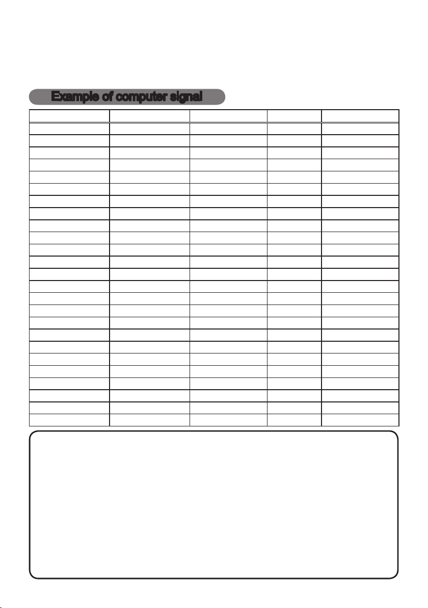
Example of computer signal
Resolution (H x V) H. frequency (kHz) V. frequency (Hz) Rating Signal mode
720 x 400
640 x 480 31.5 59.9 VESA VGA (60Hz)
640 x 480 37.9 72.8 VESA VGA (72Hz)
640 x 480 37.5 75.0 VESA VGA (75Hz)
640 x 480 43.3 85.0 VESA VGA (85Hz)
800 x 600 35.2 56.3 VESA SVGA (56Hz)
800 x 600 37.9 60.3 VESA SVGA (60Hz)
800 x 600 48.1 72.2 VESA SVGA (72Hz)
800 x 600 46.9 75.0 VESA SVGA (75Hz)
800 x 600 53.7 85.1 VESA SVGA (85Hz)
832 x 624 49.7 74.5 Mac 16” mode
1024 x 768 48.4 60.0 VESA XGA (60Hz)
1024 x 768 56.5 70.1 VESA XGA (70Hz)
1024 x 768 60.0 75.0 VESA XGA (75Hz)
1024 x 768 68.7 85.0 VESA XGA (85Hz)
1152 x 864 67.5 75.0 VESA
1280 x 768 47.7 60.0 VESA W-XGA (60Hz)
1280 x 800 49.7 60.0 VESA
1280 x 960 60.0 60.0 VESA
1280 x 1024 64.0 60.0 VESA SXGA (60Hz)
1280 x 1024 80.0 75.0 VESA SXGA (75Hz)
*1280 x 1024 91.1 85.0 VESA SXGA (85Hz)
1440 x 900 55.9 59.9 VESA WXGA+ (60Hz)
1680 x 1050 65.3 60.0 VESA WSXGA+ (60Hz)
*1600 x 1200 75.0 60.0 VESA UXGA (60Hz)
37.9 85.0 VESA TEXT
1152 x 864 (75Hz)
1280 x 800 (60Hz)
1280 x 960 (60Hz)
NOTE • Be sure to check jack type, signal level, timing and resolution before
connecting this projector to a PC.
• Some PCs may have multiple display screen modes. Use of some of these modes
will not be possible with this projector.
• Depending on the input signal, full-size display may not be possible in some cases.
Refer to the number of display pixels above.
• Although the projector can display signals with resolution up to UXGA (1600x1200),
the signal will be converted to the projector’s panel resolution before being displayed.
The best display performance will be achieved if the resolutions of the input signal
and projector panel are identical.
• Automatic adjustment may not function correctly with some input signals.
• The image may not be displayed correctly when the input sync signal is a composite
sync or a sync on G.
• The HDMI
TM
input does not support the signals marked with *.
1

2
Initial set signals
Back porch (B) Front porch (D) Back porch (b) Front porch (d)
Active video (C)
Data Data
H. Sync. V. Sync.
Sync (A) Sync (a)
Active video (c)
Initial set signals
The following signals are used for the initial settings. The signal timing of some
computer models may be different. In such case, adjust the items V POSITION
and H POSITION in the IMAGE menu.
Resolution
(H x V)
720 x 400
640 x 480 3.8 1.9 25.4 0.6 2 33 480 10 VGA (60Hz)
640 x 480 1.3 4.1 20.3 0.8 3 28 480 9 VGA (72Hz)
640 x 480 2.0 3.8 20.3 0.5 3 16 480 1 VGA (75Hz)
640 x 480 1.6 2.2 17.8 1.6 3 25 480 1 VGA (85Hz)
800 x 600 2.0 3.6 22.2 0.7 2 22 600 1 SVGA (56Hz)
800 x 600 3.2 2.2 20.0 1.0 4 23 600 1 SVGA (60Hz)
800 x 600 2.4 1.3 16.0 1.1 6 23 600 37 SVGA (72Hz)
800 x 600 1.6 3.2 16.2 0.3 3 21 600 1 SVGA (75Hz)
800 x 600 1.1 2.7 14.2 0.6 3 27 600 1 SVGA (85Hz)
832 x 624 1.1 3.9 14.5 0.6 3 39 624 1 Mac 16" mode
1024 x 768 2.1 2.5 15.8 0.4 6 29 768 3 XGA (60Hz)
1024 x 768 1.8 1.9 13.7 0.3 6 29 768 3 XGA (70Hz)
1024 x 768 1.2 2.2 13.0 0.2 3 28 768 1 XGA (75Hz)
1024 x 768 1.0 2.2 10.8 0.5 3 36 768 1 XGA (85Hz)
1152 x 864 1.2 2.4 10.7 0.6 3 32 864 1
1280 x 768 1.7 2.5 16.0 0.8 3 23 768 1 W-XGA (60Hz)
1280 x 800 1.6 2.4 15.3 0.8 3 24 800 1
1280 x 960 1.0 2.9 11.9 0.9 3 36 960 1
1280 x 1024 1.0 2.3 11.9 0.4 3 38 1024 1 SXGA (60Hz)
1280 x 1024 1.1 1.8 9.5 0.1 3 38 1024 1 SXGA (75Hz)
1280 x 1024 1.0 1.4 8.1 0.4 3 44 1024 1 SXGA (85Hz)
1440 x 900 1.4 2.2 13.5 0.8 6 25 900 3 WXGA+ (60Hz)
1680 x 1050 1.2 1.9 11.5 0.7 6 30 1050 3 WSXGA+ (60Hz)
1600 x 1200 1.2 1.9 9.9 0.4 3 46 1200 1 UXGA (60Hz)
Horizontal signal timing (μs) Vertical signal timing (lines)
(A) (B) (C) (D) (a) (b) (c) (d)
2.0 3.0 20.3 1.0 3 42 400 1 TEXT
Signal mode
1152 x 864
(75Hz)
1280 x 800
(60Hz)
1280 x 960
(60Hz)
3
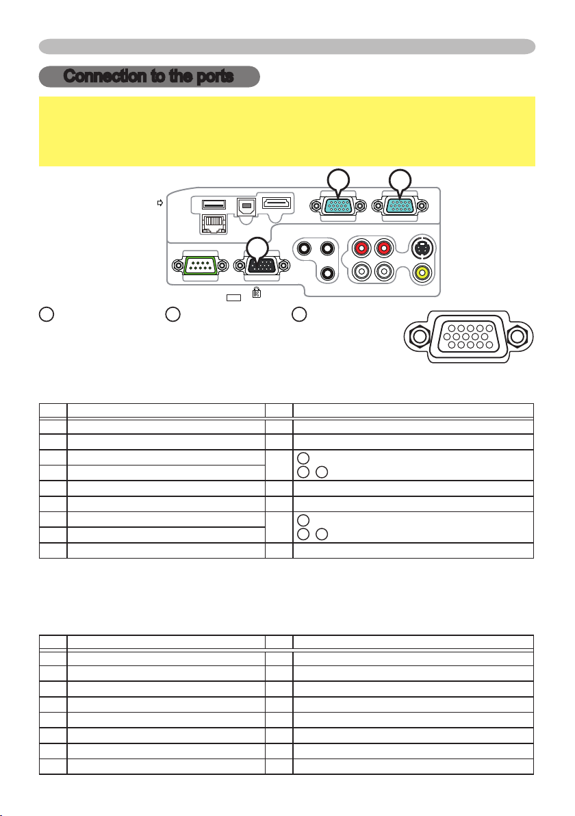
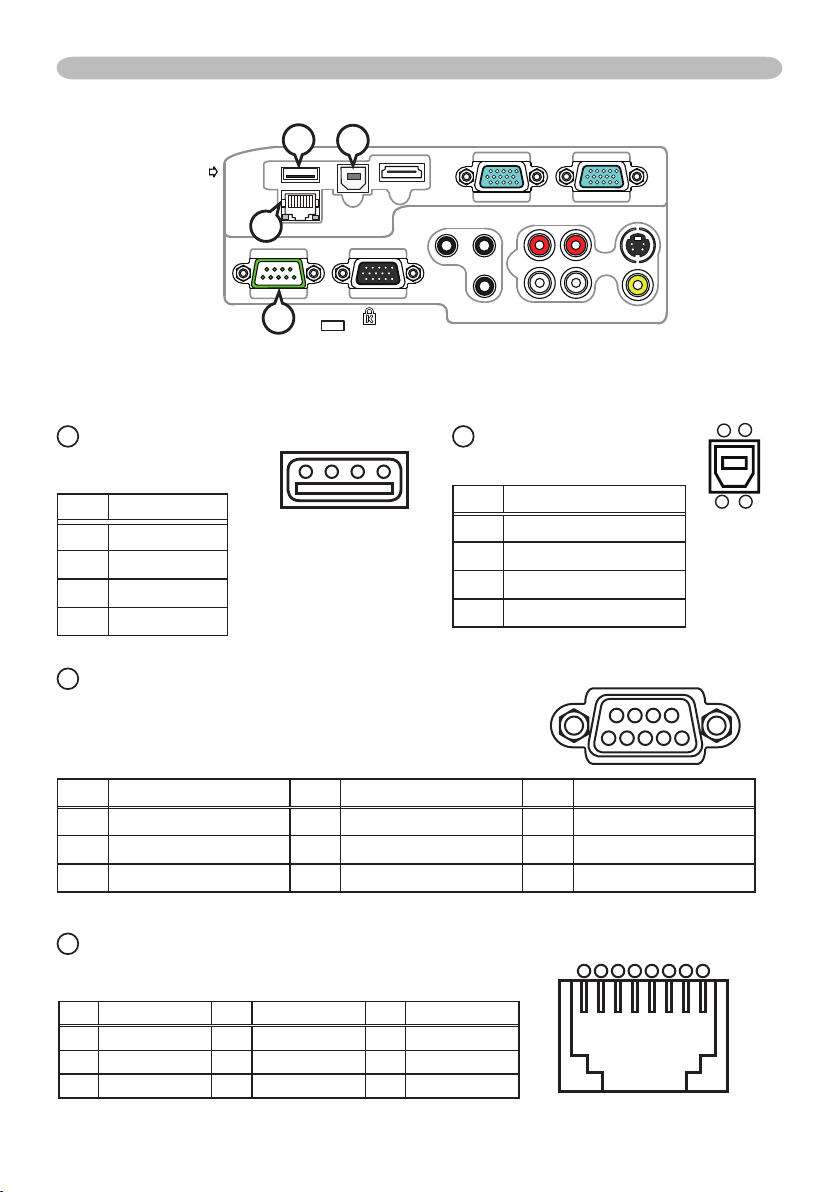
Connection to the ports
COMPUTER IN1COMPUTER IN2
HDMI
USB TYPE B
S-VIDEO
VIDEO
AUDIO OUT
AUDIO IN3AUDIO IN1
AUDIO IN2
MIC
MONITOR OUT
CONTROL
USB
TYPE A
DC5V
0.5A
Connection to the ports
NOTICE
►Use the cables with straight plugs, not L-shaped ones, as the
input ports of the projector are recessed.
►Only the signal that is input from the COMPUTER IN1 or IN2 can be output
from the MONITOR OUT port.
B
C
A
COMPUTER IN1, BCOMPUTER IN2, CMONITOR OUT
D-sub 15pin mini shrink jack
(1) for PC signal
• Video signal: RGB separate, Analog, 0.7Vp-p, 75Ω terminated (positive)
• H/V. sync. Signal: TTL level (positive/negative)
• Composite sync. Signal: TTL level
Pin Signal Pin Signal
1
Video Red 10 Ground
2 Video Green 11 (No connection)
3 Video Blue
4 (No connection)
12
A
B
: SDA (DDC data)
C
,
: (No connection)
5 Ground 13 H. sync / Composite sync.
6 Ground Red 14 V. sync.
7 Ground Green
8 Ground Blue
A
: SCL (DDC clock)
15
B
,
C
: (No connection)
9 (No connection) - -
(2) for Component signal
• Y : Component video Y with composite sync, 1.0±0.1 Vp-p, 75 Ω terminator
• Cr/Pr : Component video Cr/Pr, 0.7±0.1 Vp-p, 75 Ω terminator
• Cb/Pb : Component video Cb/Pb, 0.7±0.1 Vp-p, 75 Ω terminator
System:480i@60,480p@60,576i@50,576p@50,720p@50/60,1080i@50/60,1080p@50/60
Pin Signal Pin Signal
1
Cr/Pr 9 (No connection)
2 Y 10 Ground
3 Cb/Pb 11 (No connection)
4 (No connection) 12 (No connection)
5 Ground 13 (No connection)
6 Ground Cr/Pr 14 (No connection)
7 Ground Y 15 (No connection)
8 Ground Cb/Pb - -
A
4
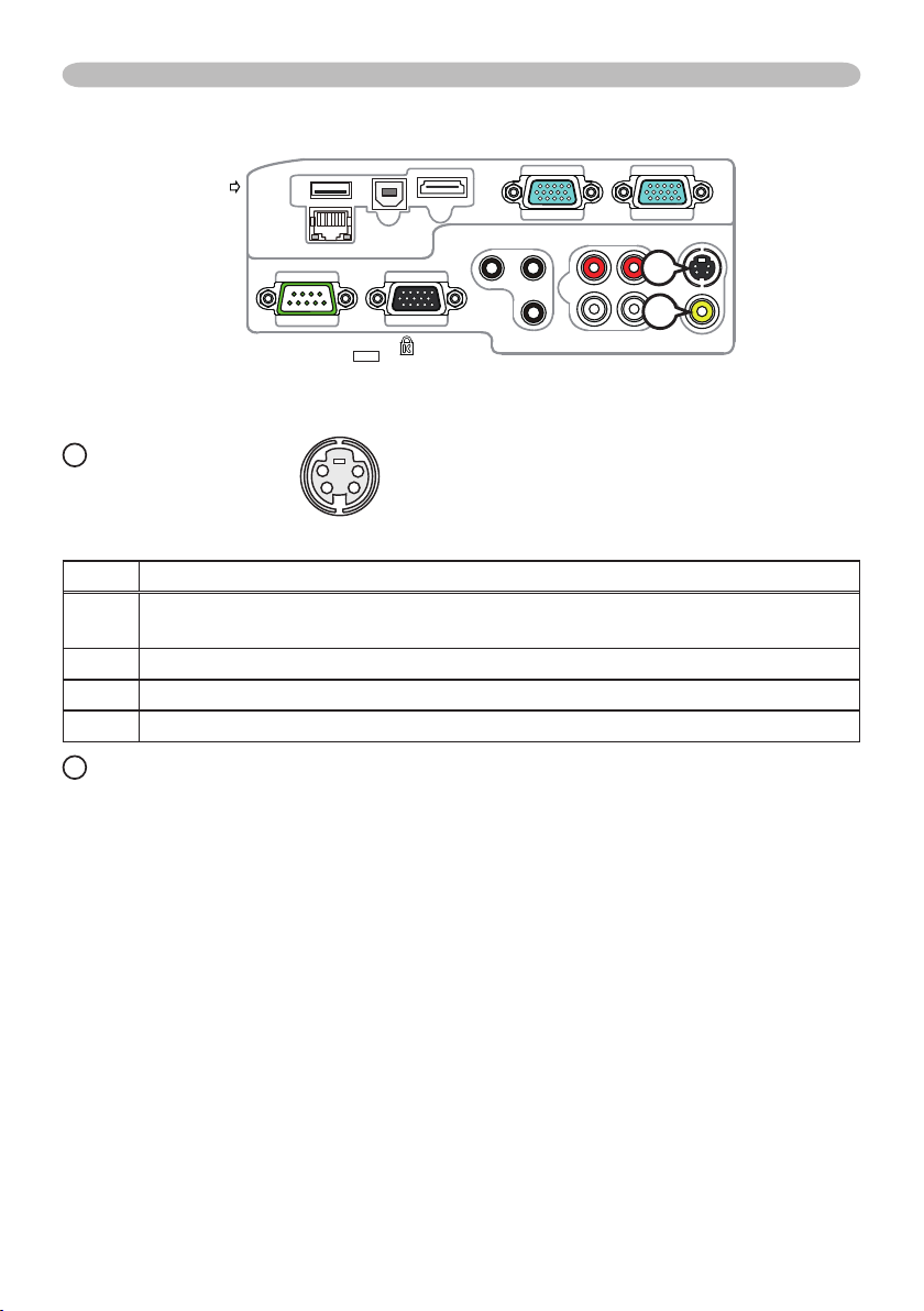
Connection to the ports (continued)
COMPUTER IN1COMPUTER IN2
HDMI
USB TYPE B
S-VIDEO
VIDEO
AUDIO OUT
AUDIO IN3AUDIO IN1
AUDIO IN2
MIC
MONITOR OUT
CONTROL
USB
TYPE A
DC5V
0.5A
D
E
D
S-VIDEO
Mini DIN 4pin jack
4
3
1
2
• System: NTSC, PAL, SECAM, PAL-M, PAL-N, NTSC4.43, PAL(60Hz)
Pin Signal
Color signal 0.286Vp-p (NTSC, burst), 75Ω terminator
1
Color signal 0.300Vp-p (PAL/SECAM, burst) 75Ω terminator
2 Brightness signal, 1.0Vp-p, 75Ω terminator
3 Ground
4 Ground
E
VIDEO
RCA jack
• System: NTSC, PAL, SECAM, PAL-M, PAL-N, NTSC4.43, PAL(60Hz)
• 1.0±0.1Vp-p, 75Ω terminator
5
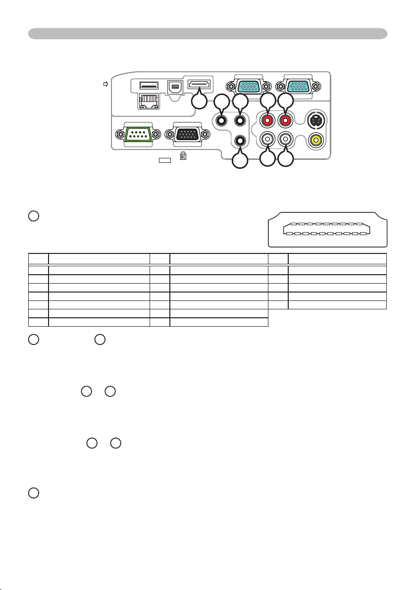
Connection to the ports (continued)
10 12 14 16 182468
911131517191357
COMPUTER IN1COMPUTER IN2
HDMI
USB TYPE B
S-VIDEO
VIDEO
AUDIO OUT
AUDIO IN3AUDIO IN1
AUDIO IN2
MIC
MONITOR OUT
CONTROL
USB
TYPE A
DC5V
0.5A
I
K
J
L
F
HDMI
F
G
M
H
• Type :Digital audio/video connector
• Audio signal : Linear PCM (Sampling rate; 32/44.1/48 kHz)
Pin Signal Pin Signal Pin Signal
1 T.M.D.S. Data2 + 8 T.M.D.S. Data0 Shield 15 SCL
2 T.M.D.S. Data2 Shield 9 T.M.D.S. Data0 - 16 SDA
3 T.M.D.S. Data2 - 10 T.M.D.S. Clock + 17 DDC/CEC Ground
4 T.M.D.S. Data1 + 11 T.M.D.S. Clock Shield
5 T.M.D.S. Data1 Shield 12 T.M.D.S. Clock - 19 Hot Plug Detect
6 T.M.D.S. Data1 - 13 CEC
7 T.M.D.S. Data0 + 14 Reserved(N.C. on device)
18
+5V Power
G
AUDIO IN1, HAUDIO IN2
Ø3.5 stereo mini jack
• 200 mVrms, 47kΩ terminator
AUDIO IN3 IR, JL
RCA jack x2
• 200 mVrms, 47kΩ terminator
AUDIO OUT KR, LL
RCA jack x2
• 200 mVrms, 1kΩ output impedance
M
MIC
Ø3.5 mono mini jack
<Low level>
• 2 mVrms, 1kΩ terminator
<High level>
• 20 mVrms, 1kΩ terminator
6
Connection to the ports (continued)
COMPUTER IN1COMPUTER IN2
HDMI
USB TYPE B
S-VIDEO
VIDEO
AUDIO OUT
AUDIO IN3AUDIO IN1
AUDIO IN2
MIC
MONITOR OUT
CONTROL
USB
TYPE A
DC5V
0.5A
N
Q
P
N
USB TYPE A
USB A type jack
3
4
Pin Signal
1 +5V
2 - Data
3 + Data
4 Ground
O
2 1
O
USB
TYPE B
USB B type jack
Pin Signal
1 +5V
2 - Data
3 + Data
4 Ground
3
4
21
P
CONTROL
D-sub 9pin plug
• About the details of RS-232C communication,
please refer to the section "RS-232C Communication".
Pin Signal Pin Signal Pin Signal
1 (No connection) 4 (No connection) 7 RTS
2 RD 5 Ground 8 CTS
3 TD 6 (No connection) 9 (No connection)
Q
LAN
RJ-45 jack
Pin Signal Pin Signal Pin Signal
1 TX+ 4 - 7 2 TX- 5 - 8 3 RX+ 6 RX-
6
9
8
7
5 4 3 2 1
87654321
7
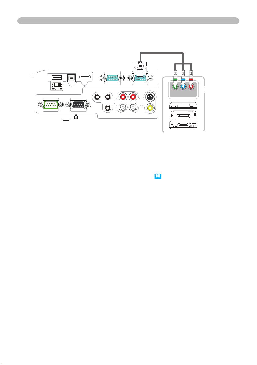
Connection to the ports (continued)
Y CB/PB CR/PR
COMPONENT VIDEO OUT
COMPUTER IN1COMPUTER IN2
HDMI
USB TYPE B
S-VIDEO
VIDEO
AUDIO OUT
AUDIO IN3AUDIO IN1
AUDIO IN2
MIC
MONITOR OUT
CONTROL
USB
TYPE A
DC5V
0.5A
To input component video signal to COMPUTER IN ports
ex.
D-sub plug
RCA plugs
RCA connectors
VCR/DVD/Blu-ray
Disc player
To input component video signal to the COMPUTER IN1 or IN2 port of the
projector, use a RCA to D-sub cable or adapter.
For about the pin description of the required cable or adapter, refer to the
descriptions about COMPUTER IN1 and IN2 port (
&3
).
8
RS-232C Communication
RS-232C Communication
When the projector connects to the computer by RS-232C communication, the
projector can be controlled with RS-232C commands from the computer.
For details of RS-232C commands, refer to RS-232C Communication / Network
command table (
&17
).
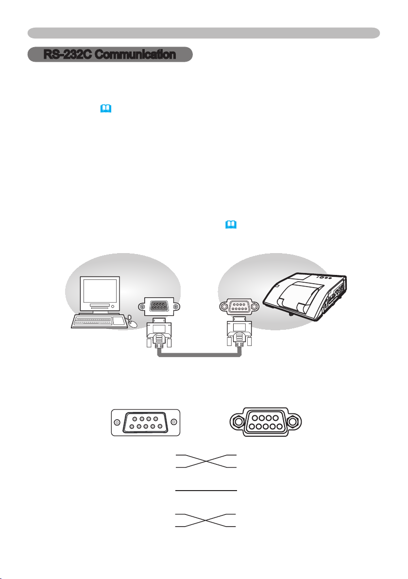
Connection
1.
Turn off the projector and the computer.
2.
Connect the projector's CONTROL port and the computer's RS-232C port
with a RS-232C cable (cross). Use the cable that ful lls the speci cation
shown in gure
3.
Turn the computer on, and after the computer has started up turn the projector
on.
4.
Set the COMMUNICATION TYPE to OFF. (
&
OPTION menu - SERVICE -
COMMUNICATION in the User's Manual - Operating Guide)
(cross)
RS-232C Cable
RS-232C
CONTROL
CD (1) (1)
−
RD(2) (2) RD
TD (3) (3) TD
DTR (4) (4)
−
GND (5) (5) GND
DSR (6) (6)
−
RTS (7) (7) RTS
DTS (8) (8) CTS
RI (9) (9)
−
CONTROL port
of the projector
RS-232C port
of the computer
9
5 4 3 2 1
6
7
8
1
2
4
3
8
9
5
7 6

9
Communicaion settings
1. Protocol
19200bps,8N1
2. Command format
("h" shows hexadecimal)
RS-232C Communication (continued)
Byte Number
Command
Action
<SET>
Change setting to
desired value [(cL)(cH)]
by [(eL)(eH)].
<GET>
Read projector
internal setup value [(bL)
(bH)] .
<INCREMENT>
Increment setup value
[(bL)(bH)] by 1.
<DECREMENT>
Decrement setup value
[(bL)(bH)] by 1.
<EXECUTE> Run a
command [(bL)(bH)].
0 1 2 3 4 5 6
Header Data
Header
code
L H L H L H L H L H L H
BEh EFh 03h 06h 00h
Packet
Data
size
CRC
ag
(aL) (aH) 01h 00h (bL) (bH) (cL) (cH)
(aL) (aH) 02h 00h (bL) (bH) 00h 00h
(aL) (aH) 04h 00h (bL) (bH) 00h 00h
(aL) (aH) 05h 00h (bL) (bH) 00h 00h
(aL) (aH) 06h 00h (bL) (bH) 00h 00h
[Header code] [Packet] [Data size]
Set [BEh, EFh, 03h, 06h, 00h] to byte number 0
~
4.
[CRC ag]
For byte number
table
(&17).
5, 6,
refer to
RS-232C Communication / Network command
[Action]
Set functional code to byte number 7, 8.
SET
<
> = [01h, 00h], <
GET
> = [02h, 00h], <
INCREMENT
<DECREMENT> = [05h, 00h], <EXECUTE> = [06h, 00h]
(
Refer to the Communication command table
&above
[Type] [Setting code]
For byte number
table
(&17).
9~12
, refer to
RS-232C Communication / Network command
7 8 9 10 11 12
Action Type
Setting
code
> = [04h, 00h]
).

10
RS-232C Communication (continued)
3. Response code / Error code
("h" shows hexadecimal)
(1) ACK reply : 06h
When the projector receives the Set, Increment, Decrement or Execute
command correctly, the projector changes the setting data for the specied
item by [Type], and it returns the code.
(2) NAK reply : 15h
When the projector cannot understand the received command, the projector
returns the error code.
In such a case, check the sending code and send the same command again.
(3) Error reply : 1Ch + 0000h
When the projector cannot execute the received command for any reasons,
the projector returns the error code.
In such a case, check the sending code and the setting status of the projector.
(4) Data reply : 1Dh + xxxxh
When the projector receives the GET command correctly, the projector returns
the responce code and 2 bytes of data.
NOTE •
For connecting the projector to your devices, please read the
manual for each devices, and connect them correctly with suitable cables.
• Operation cannot be guaranteed when the projector receives an undened
command or data.
• Provide an interval of at least 40ms between the response code and any other
code.
• The projector outputs test data when the power supply is switched ON, and
when the lamp is lit. Ignore this data.
• Commands are not accepted during warm-up.
When the data length is greater than indicated by the data length code, the
•
projector ignore the excess data code. Conversely when the data length is
shorter than indicated by the data length code, the projector returns the error
code to the computer.
 Loading...