

Page 1
HITACHI
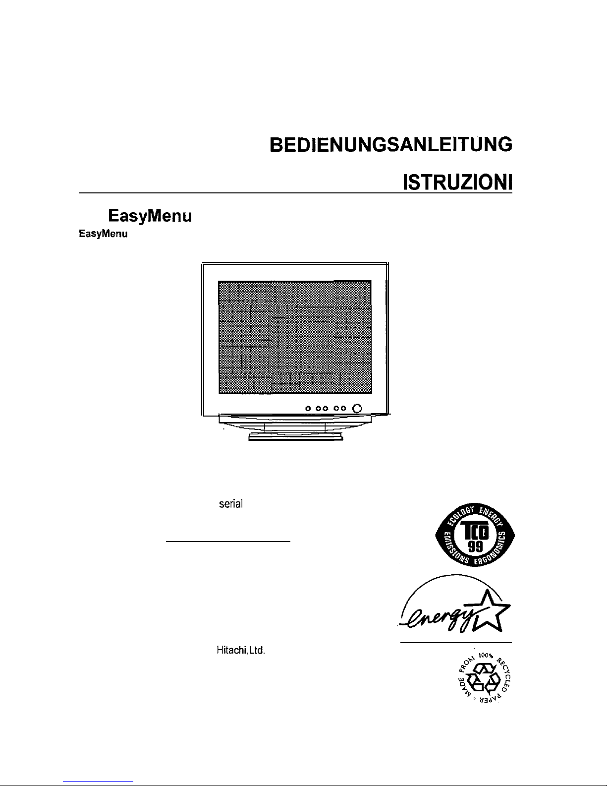
FLAT FACE COLOUR MONITOR
(DJ72)
USER MANUAL
MANUEL D’UTILISATION
MANUAL DE USUARIO
MANUALE DI
with
!
is HITACHI’s On Screen Display function for easy operation.
READ THE INSTRUCTIONS INSIDE CAREFULLY.
KEEP THIS USER MANUAL FOR FUTURE REFERENCE.
For future reference, record the serial number of your colour monitor.
SERIAL No.
The serial number is located on the rear of the monitor.
This monitor is ENERGY STAR@ compliant when used with a
computer equipped with VESA DPMS.
The ENERGY STAR@ emblem does not represent EPA endorsement
of any product or service.
AS an ENERGY STAR@ Partner,
has determined that this
product meets the
E
NERGY STAR
@ guidelines
for energy efficiency.
CM771ET/U
CM772ET/U
Page 2

Page 3
HITACHI
Colour Monitor
(DJ72)
CM771ET
.
USER MANUAL
Congratulations on your selection of the HITACHI Colour Monitor.
Read the instructions inside carefully, and keep this user manual for future
reference.
NOTE:
* The information in this manual is subject to change without notice. The manufacturer
assumes no responsibility for any errors that may appear in this manual.
* The reproduction, transmission or use of this documents or contents is not permitted
without express written authority.
TRADEMARK ACKNOWLEDGEMENT:
VGA is a registered trademark of International Business Machines Corporation.
VESA is a trademark of a nonprofit organisation, Video Electronics Standard
Association.
E
NERGY
is a trademark of Environmental Protection Agency (EPA).
CONTENTS
FEATURES .................................................................................................
1
2
.............................................................
............................... 1
3
INSTALLATION ...........................................................................................
7
......................................................................................
........1 9
POWER SAVING SYSTEM .......................................................................
1
15
PLUG & PLAY ........................................................................................... 1
15
CHECK...
.....................................................................................
1
15
TROUBLESHOOTING
.............................................................................. 1
16
.....................................................................................
1
17
Tables:
Table
Adjustment
..............................................................
............... 1
10
Table l-2. Power Saving System
..............................................................
1
15
Table
l-3. Signal
Check
............................................................................ 1
15
Table 1-4. Troubleshooting ........................................................................ 1
16
Table
l-5. Standard
Settings ..................................................................... 1
18
Table 7-6. Pin Assignment ........................................................................ 1
19
l-l
CM772ET
Page 4
The
following features are provided in this Colour Monitor.
Sharpest Focus and Highest Contrast
Flat screen Enhanced Dot Pitch (EDP) CRT with anti-glare, dynamic focus circuit, dark
glass and an
shadow mask gives the sharpest focus and highest contrast to
n -
eye fatigue.
Wide-range Multi-Scanning
Automatic scanning and automatic adjustment to conform with a wide range of scanning
frequencies and user requirements.
Digital Picture Control Function
Position, size, pincushion, trapezoid, parallelogram etc. are adjustable by digital controls.
Geometry settings can be stored for different HIV frequencies.
Microprocessor-based
preset functions can store 37 sets of geometry settings including the standard factory
settings.
Digital Colour Control Function
Red, green, and blue colour balance is adjustable by digital control. An adjusted colour
setting can be stored and recalled by the colour select function.
Power Saving System
The Environmental Protection Agency (EPA) has established a voluntary program by
which manufacturers enable computer products to go into low power states while not
being used. This monitor has a low power “sleep” mode, which is compliant with the EPA
requirements for the ENERGY STAR@ program, and will assist you in conserving energy.
Please refer to the section of “POWER SAVING SYSTEM” for details.
An On Screen Display function that allows easy access to adjust all operations from the
front panel.
Plug
Play
This monitor is VESA
compliant when used with a computer compliant with
VESA DDC (Display Data Channel).
l-2
Page 5
Discontinue Usage if Abnormal Operation Occurs !
Abnormal operations such as smoke, burning smell, excessive sound, etc. could cause
fire or electrical shock. If you observe any abnormal operation, you should turn Off the
monitor and disconnect the power plug from the power outlet.
You should check for
smoke or fire and contact your dealer.
Do not expose the monitor to physical impact !
Do not allow foreign objects (water, metal, etc.) inside !
Never remove the cover !
The colour monitor contains high voltage components.
Ask your dealer to repair or
clean inside.
The power outlet should be close to the monitor and easily accessible !
Install the unit in an suitable environment !
Do not expose the monitor to rain, moisture, dust, corrosive gases, vibrations, etc. so as
to prevent electrical shock or fire hazard.
Avoid placing the monitor in direct sunlight or near heating appliances.
Do not place the monitor on an unstable base.
Keep in a well ventilated area !
Do not cover this monitor or place anything against any sides (not only the top, right and
left side but also the rear and bottom sides) of the monitor. Ventilation holes are
provided at all sides of covers to prevent excessive temperature increase.
DO NOT place a magnet, loudspeaker system, floppy disk drive, printer, or anything
which will generate magnetism near the unit. A magnetic field may cause blurred
colours or distortion of the displayed pattern.
Be mindful of the ambient illumination !
Avoid direct rays of the sun or room lighting onto the CRT screen in order to prevent eye
fatigue.
The enclosed power cord must be used !
Failure to do so may cause fire or electrical shock hazard.
Use only the correct voltage power outlet with safety ground connection !
This monitor will automatically adjust to the input voltage 100
120
240V.
Be cautious of the power cord connection !
Before inserting the plug of the power cord into a power outlet of the correct voltage,
check that the connection portion of the power cord is clean (with no dust). Then,
insert the plug of power cord into a power outlet firmly to avoid electrical shock or fire
hazard.
Remove the power cord for complete separation !
For complete separation from the power source, remove the power cord from the
monitor
or
from the wall power outlet.
l-3
Page 6
(Continued)
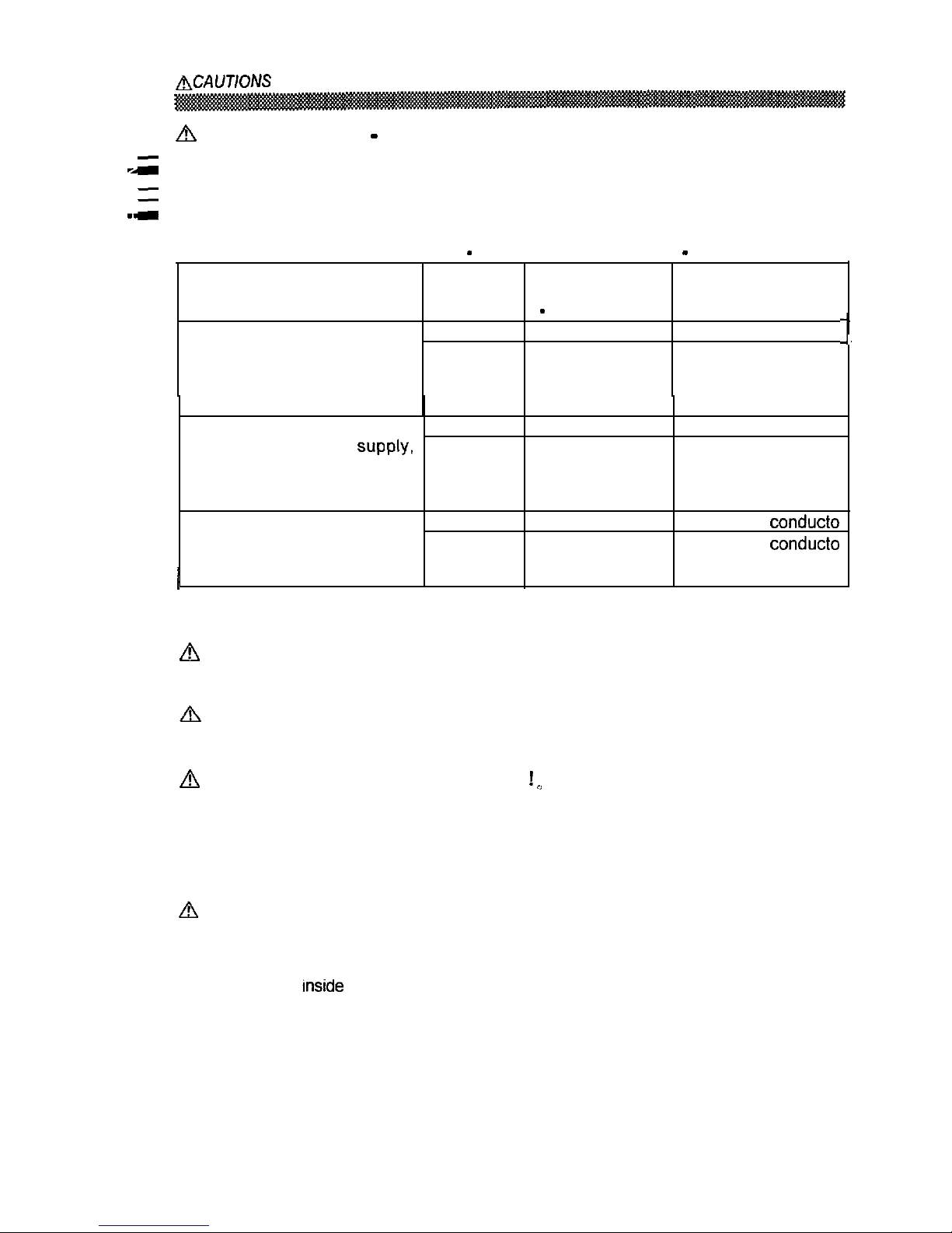
CAUTION for 200
240V operation only
This equipment relies on the protective devices in the building installation for
short-circuit and over-current protection. Refer to the following table for the suitable
number and location of the protective devices which should be provided in the building
installation.
Informative examples of
protective devides
in
single
phase equipment or sub
assemblies
Protection Minimum number
Location
against
of fuses or circuit
breaker poles
Case A: Equipment to be Earth faults
1
Phase conductor
connected to POWER SYSTEMS Overcurrent
1
Either of the two
with earthed neutral reliably
conductors
identified, except for Case C
below.
Case B: Equipment to be Earth faults
2
Both conductors
connected to any
Overcurrent
1
Either of the two
including IT POWER SYSTEMS
conductors
and supplies with reversible
plugs, except for Case C below.
Case C:
Equipment to be Earth faults
2
Each phase conduct0
r
connected to 3-wire power Overcurrent
2
Each phase conduct0
r
reliably identified.
I
Verify that the protective devices in the building installation meets the conditions in the
table prior to installing the equipment.
Be careful of static electricity on CRT surface !
To prevent electrical shock by the static electricity on the CRT surface, disconnect the
power cord at least 30 seconds after turning OFF the power.
Avoid frequent power ON-OFF switching !
Do not repeat OFF and ON power switching in a short period. This may cause blurred
colours or distortion of the displayed pattern.
Be careful of generated magnetism
After the power has been turned ON or when the degauss function has been manually
engaged, the CRT is demagnetised for approximately 7 seconds. This generates a
strong magnetic field around the front cover which may affect the data stored on
magnetic tape or disks near the front cover. Place such magnetic recording equipment
and tapes/disks away from this unit.
About cleaning
Before cleaning, turn OFF the power switch and disconnect the plug from the power outlet.
For the screen, use water with a lightly moistened soft cloth such as a gauze type material.
For the cover, use water or a liquid synthetic detergent, with a lightly moistened soft cloth.
Do not clean the
of monitor by yourself as it is very dangerous. Refer to your dealer.
Do not use aerosol sprays, solvents or abrasive cleaners.
l-4
Page 7
(Continued)
FCC Statement Warning
WARNING : This equipment has been tested and found to comply with the limits for a
Class B digital device, pursuant to Part 15 of the FCC Rules. These limits are
designed to provide reasonable protection against harmful interference in a residential
installation. This equipment generates, uses, and can radiate radio frequency energy
and, if not installed and used in accordance with the instructions, may cause harmful
interference to radio communications.
However, there is no guarantee that interference
will not occur in a particular installation.
If this equipment does cause harmful
interference to radio or television reception, which can be determined by turning the
equipment off and on, the user is encouraged to try to correct the interference by one or
more of the following measures:
Reorient or relocate the receiving antenna.
Increase the separation between the equipment and receiver.
Connect the equipment into an outlet on a circuit different from that to which the
receiver is connected.
Consult the dealer or an experienced radio! TV technician for help.
INSTRUCTIONS TO USERS : This equipment complies with the requirements of FCC
(Federal Communication Commission) equipments provided that following conditions are met
(1) Power cord: Unshielded power cord must be used.
(2) Video inputs: The input signal amplitude must not exceed the specified level.
CAUTION : Changes or modifications not expressly approved by the party responsible
for compliance could void the user’s authority to operate the equipment.
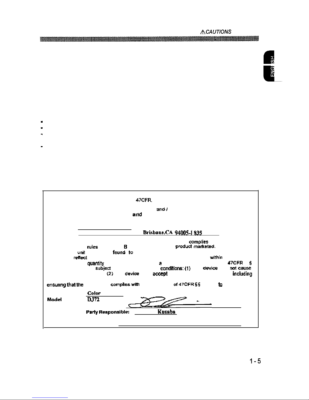
Declaration of Conformity
According to 47CFR. Part 2 and
15
for
Class B Personal Computers end
Peripherals: and) or
CPU Boards
Power Supplies used
with Class B Personal Computers:
we: Hitachi America, Ltd.
Located at:
2000 Sierra
Point Parkway,
$35
U.S.A.
Declare under sale responsibility
that
the
product
identified herein.
with
47CFR Part 2
and
15 of the FCC rules as a Class B digital device.
Each
is identical to the
representative unit tested
and
be
compliant
with the standards. Records
maintained
continue to
the equipment being produced can be expected to be
the variation
accepted.
due
to
as
required by 47CFR
2.909.
Operation is
to the following two
This
may
harmful interference. and
This
must
any interference received.
interference that may cause undesired operation
The above named
party is responsible for
equipment
the standards
15.101
15.109.
Trade name:
Monitor
Number:
Signature of Party Responsible:
Printed name of
Hidenki Kusaba
Executed on {Date}. at
[Place):
April 10, 2000, CA, U.S.A.
For the Customers in CANADA
NOTICE : This Class B digital apparatus complies with Canadian ICES-003.
Page 8
(Continued)
For the Customers in fhe UK
THIS PRODUCT IS SUPPLIED WITH A TWO PIN MAINS PLUG FOR USE IN MAINLAND
EUROPE. FOR THE UK PLEASE REFER TO THE NOTES ON THIS PAGE.
IMPORTANT FOR UNITED KINGDOM
WORDING FOR CLASS I EQUIPMENT INSTRUCTION BOOKS AND LABELS
The mains lead on this equipment is supplied with a moulded plug incorporating a fuse,
the value of which is indicated on the pin face of the plug.
Should the fuse need to be
replaced, an ASTA or BSI approved BS 1362 fuse must be used of the same rating.
If the fuse cover is detachable never use the plug with the cover omitted.
If a
replacement fuse cover is required, ensure it is of the same colour as that visible on the
pin face of the plug. Fuse covers are available from your dealer.
DO NOT cut off the mains plug from this equipment.
If the plug fitted is not suitable for
the power outlets in your home or the cable is too short to reach a power outlet, then
obtain an appropriate safety approved extension lead or consult your dealer.
Should it be necessary to change the mains plugs, this must be carried out by a
competent person, preferably a qualified electrician.
If there is no alternative to cutting off the mains plug, ensure that you dispose of it
immediately, having first removed the fuse, to avoid a possible shock hazard by
inadvertent connection to the mains supply.
WARNING: THIS EQUIPMENT MUST BE EARTHED
IMPORTANT
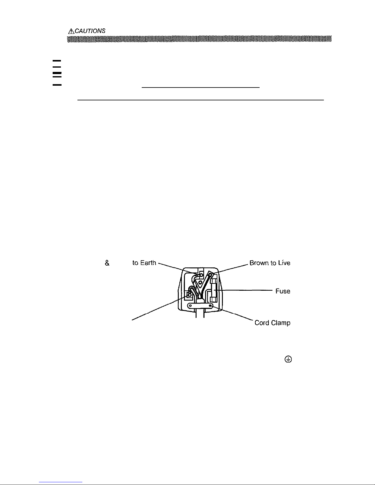
The wires in the mains lead are coloured in accordance with the following code:
Green and Yellow = Earth, Blue = Neutral, Brown = Live.
Green & Yellow
Blue to Neutral
As these colours may not correspond with the coloured markings identifying the
terminals in your plug, proceed as follows:
The wire which is coloured GREEN and YELLOW must be connected to the terminal in
the plug which is marked with the letter E or by the earth symbol
or coloured
GREEN or GREEN and YELLOW.
The wire coloured BLUE must be connected to the terminal marked with the letter N or
coloured BLUE or BLACK. The wire coloured BROWN must be connected to the
terminal marked with the letter L or coloured BROWN or RED.
l-6
Page 9

INSTALLATION
Before installing, read the chapter “CAUTIONS” carefully.
Checking the contents
Check whether the consignment agrees with the details in the following delivery note.
Should you discover that the equipment has been damaged during transport or that the
consignment does not correspond to the delivery note, notify your dealer immediately.
Delivery
Note: one Monitor
one Power Cord
this User Manual
NOTE:
Keep the original packing material for future reshipment.
l-7
Page 10

INSTALLATION (Continued)
Connecting the monitor
Rear Cover
Signal Input Connector
Base
Front View
Rear View
to a power outlet to
the host
of the
correct voltage computer
1. Installation
Install the monitor in an suitable environment.
Do not place the monitor on an unstable base.
Do not expose th
e monitor to rain, moisture, dust, corrosive gases, vibrations, etc.
so as to prevent electrical shock or fire hazard.
Avoid placing the monitor in direct sunlight or near heating appliances.
2. Signal Cable Connection
Insert the signal input connector of the monitor to the host computer, with attention to the
suitability, and secure the screws on the connector shell firmly.
3. Power Cord Connection
(1) Make sure to use the power cord meeting the safety standard of the country in which
you are using the monitor.
(2) Insert the connector of a power cord to the AC Inlet of the monitor.
(3) Insert the plug of the power cord to a power outlet of the correct voltage.
Before inserting the plug of the power cord into a power outlet of the correct voltage,
check that the connection portion of the power cord is clean (with no dust).
Then,
insert the plug of power cord into a power outlet firmly to avoid electrical shock or fire
hazard.
Page 11

OPERATION
Power ON/OFF
Press the power switch, to switch the power ON or OFF. When power is ON, the
.
power indicator lights.
NOTE:
* Turn on the monitor first, then the computer.
* After turning OFF the power switch, wait at least 5 seconds before restarting the monitor.
If this 5 second delay is not observed, the monitor may operate incorrectly.
Brightness/Contrast Adjustment
(1) Press one of the adjustment buttons when the OSD
(On Screen Display) is not shown. The OSD
function
then shows the condition of
brightness and contrast.
(2) To adjust, use the adjustment buttons
for
brightness, and
for contrast.
Other Functions
Brightness/C
(1) Press the menu button when the OSD is not shown.
The OSD function
then shows the main
menu.
has 4 sub menus (Screen Menu,
Recall Menu, OSD Menu and Color Menu). You
can call them by the functions of the main menu.
(2) To select the function of the menu, use the
Main Menu
adjustment buttons @I/@.
(3) To execute the selected function, use the adjustment
buttons
in the Table l-l overleaf.
NOTE:
You can select the OSD language.
Use the function “LANGUAGE SELECT” of the
“OSD MENU”.
* To return to the main menu from any sub menu, press the menu button.
* To’clear the OSD, press the menu button at the main menu, use the function “OSD
EXIT”, or wait for a definite period.
* The adjusted condition will be stored automatically at clearing the OSD.
* The OSD might be turned on and off continuously in a short period when the OSD is
displayed in a certain position of the screen.
This phenomenon is not a failure.
Simply
change the OSD position a little up or down, so that the OSD will be stable.
l-9
Page 12

OPERATION (Continued)
Table
1-l.
DEGAUSS
DMS
COLOR MENU?
COLOR SELECT
OSD MENU?
RECALL MENU?
SCREEN MENU?
ROTATION
PIN. BALANCE
PARALLELOGRAM
PINCUSHION
TRAPEZOID
POSITION
V. SIZE
TRAPEZOID
PINCUSHION
PARALLELOGRAM
PIN. BALANCE
ROTATION
SCREENMENU?
RECALL MENU?
OSD MENU?
COLOR SELECT
COLOR MENU?
DMS
DEGAUSS
OSD EXIT
(To be continued on the
next page.)
I-10
Adjustments
Page 13

OPERATION (Continued)
Table 1-I. Adjustment (Continued)
Item
Function
(no function)
I
RECALL MENU ?
COLOR MENU ?
DMS
(no function)
calls “COLOR MENU”.
cancels the DMS mode. (NO)
set the DMS mode. (YES)
DEGAUSS
dynamic motion picture system.
(no function)
executes degaussing. (YES)
(To be continued on the next page.)
I-II
Page 14

OPERATION (Continued)
r
Table l-l.
Item
(MAIN MENU)
SCREEN MENU
(To be continued on the next page.)
ustment
T
Function
(unavailable) (NO)
clears the OSD.
shrinks horizontally and vertically.
expands horizontally and vertically.
changes to the previous mode.
H. MOIRE
HEMISPHERE
V. LIN. BALANCE
V. LINEARITY
BOTTOM CORNER
TOP CORNER
V. FOCUS
H. FOCUS
V. MOIRE
H. MOIRE
changes to the next mode.
H. MOIRE
V. MOIRE
H. FOCUS
V. FOCUS
TOP CORNER
BOTTOM CORNER
V. LINEARITY
V. LIN. BALANCE
HEMISPHERE
H. MOIRE
makes the operation of the horizontal moire
changing circuit weaker.
makes the operation of the horizontal moire
changing circuit stronger.
makes the operation of the vertical moire
changing circuit weaker.
makes the operation of the vertical moire
changing circuit stronger.
* Moire may appear on the screen due to interference between CRT dot pitch and
video signal by conditions of video image, display size, display brightness, etc.
Adjust the conditions of display size, display brightness, etc., before the adjustment
of moire.
* In some cases, this function may cause deterioration of display quality, such as
focus, jitter, etc.
I-12
Page 15

OPERATION
Adjustment
button
Function
recalls all factory settings and delete the all
user settings. (YES)
To
activate the TOTAL
RESET command,
o
continued on the next page.)
1-13
Table 1-1
Page 16

OPERATION (Continued)
7
‘able l-l. Adjustment (Continued)
Item Adjustment
OSD MENU
R RED
G GREEN
B BLUE
Function
changes to the previous mode.
OSD H. POS.
LANGUAGE SELECT
OSD V. POS.
OSD H. POS.
changes to the next mode.
OSD H. POS.
OSD V. POS.
LANGUAGE SELECT
OSD H. POS.
moves the OSD to the left.
moves the OSD to the right.
moves the OSD down.
moves the OSD up.
changes to the previous mode.
ENGLISH
(French)
ITALlANO (Italian)
ESPANOL (Spanish)
DEUTSCH (German)
ENGLISH
changes to the next mode.
ENGLISH
DEUTSCH (German)
ESPANOL (Spanish)
ITALIAN0 (Italian)
(French)
ENGLISH
changes to the previous mode.
changes to the next mode.
R
B
R
makes the Green and Blue stronger.
When the Green or Blue reaches the upper
’
limit, it makes the Red weaker.
makes the Red stronger.
When the Red reaches the upper limit, it
makes the Green and Blue weaker.
makes the Blue and Red stronger.
When the Blue or Red reaches the upper
limit, it makes the Green weaker.
makes the Green stronger.
When the Green reaches the upper limit, it
makes the Blue and Red weaker.
makes the Red and Green stronger.
When the Red or Green reaches the upper
limit, it makes the Blue weaker.
makes the Blue stronger.
When the Blue reaches the upper limit, it
makes the Red and Green weaker.
Page 17

POWER SAVING SYSTEM
.
This monitor complies with VESA and
E
NERGY STAR
*
power saving requirements.
The
power saving system works only when used with VESA DPMS compliant PC’s
graphic controllers,
,
Table 1-2. Power Saving System
VESA DPMS
Power Saving States
Power Saving
Video
H. Sync. V. Sync.
Power Power Indicator
Mode
ON
Active
Yes Yes 98 W (typical) Lighting Green
Stand-by
Blanked No
Yes Less than IO W
Suspend Blanked Yes No Lighting Orange
Active OFF Blanked No
No Less than 3 W
When to switch the power Off during the monitor is in Active OFF mode, sometimes
the power indicator lighting continues a few seconds. It is not failure.
& PLAY
This monitor complies with VESA
specifications. Plug
Play is a system, by
which computer, peripherals (including monitors), and operating system manufacturers
comply with for this user-friendly function. It works when the monitor is connected to
DDC ready computer that is running an operating system software that incorporates
Plug
Play functionality.
SIGNAL CHECK
Your monitor is equipped with an automatic Signal Verification System.
The Table l-3
below outlines the operation of this system.
Table 1-3. Signal Check
Signal Condition Indication of OSD Power Indicator State
Proper signal is detected The OSD indicates the horizontal The power indicator lights
by the monitor.
frequency and vertical frequency green.
on the adjustment menu.
No Sync. Signal is detected The OSD indicates the message After 10 seconds, the
by the monitor. “POWER SAVE” for 5 seconds colour of the power
after which time the unit will turn indicator will turn to
into Power Saving Mode. orange.
A video signal is applied The OSD indicates the message The power indicator will
to the monitor that is “INVALID SCAN FREQ.“.
be illuminated as a solid
beyond the monitor scan green colour.
range.
-15
Page 18

The following Table l-4 is provided to assist you in common installation issues.
Table l-4. Troubleshooting
Symptom
Solution
No power
Verify the power cord is installed correctly.
Press the power switch.
No picture Increase Contrast and Brightness.
No picture and the power indicator Check Signal Cable Connection.
lights orange
Check Power Connection to computer.
“POWER SAVE” message appears Check Signal Cable Connection.
Check Power Connection to computer.
“INVALID SCAN
message Check Signal Cable Connection.
appears
Check video input specification.
Wavy or elliptical (moire) pattern Adjust unit with moire control as outlined in the
appears
Table l-l.
Colour is not uniform Activate Degauss function.
Environmental influences
Check to see that no magnetic appliance such
as telephones,
fans, or
I-16
Page 19

CRT
FLAT Screen 19 inch type picture tube, 0.22 mm horizontal dot pitch, 0.21 mm
horizontal mask pitch, lnvar shadow mask, Black matrix, Short persistence phosphors,
.
Dark tint, Anti-Reflection coat.
input Signal
Video
: 0.70 Vp-p, Analogue
Sync.
: Separate
TTL level
Composite H/V, TTL level
Sync. on Green at 0.30 Vp-p
Synchronisation
Horizontal
: 31
96
31
115
Vertical
:
160 Hz
Resolution
Horizontal : up to 1600 dots
Vertical : up to 1280 lines
Video Clock Frequency :
CM771 ET CM772ET
200 MHz (typical) 230 MHz (typical)
.
Viewabk image Size
: 18.0 inches (457mm), diagonal (typical)
Image Area
Horizontal : 365 mm (typical)
Vertical
: 275 mm (typical)
Colour
Temperature
9300 : Standard colour balance, 9300K
6500 : Standard colour balance, 6500K
5000 : Standard colour balance,
USER : User defined
DMS : Standard colour balance, 9300K for the DMS mode
Power Supply
AC 100
120 I200
240 V
(automatically selected)
Power Consumption : 98 W (typical) (provided with power save circuit)
Warm-up
Time
: 30 minutes to reach optimum performance level.
Dimensions
: 448 (W) x 442 (H) x 450 (D) mm (including Tilt & Swivel Base)
Weight
: 24.0 kg (approx.) (including Tilt & Swivel Base)
Environmental Condition
Operating Temperature
: 5 to 35
Operating Relative Humidity : 10 to 80 % without condensation
Storage Temperature
: -20 to 60
Storage Relative Humidity
:
10 to 90 % without condensation
I-17
Page 20

SPECIFICATIONS (Continued)
Standard Settings
Microprocessor-based preset functions can store 37 sets of geometry settings including
the standard settings. The following industrial standard settings have been
pre-programmed by the factory.
as the same
* The following horizontal timing conditions are recommended (at sync. H, V separate
or HN composite).
for 31 kHz
55 kHz horizontal frequency:
Horizontal front porch should be more than 0.1 us.
Horizontal sync. width should be within 1.0
3.8 us.
Horizontal back porch should be more than 1.2 us.
Horizontal blanking width should be more than 3.5 us.
for 55 kHz
115 kHz horizontal frequency:
Horizontal front porch should be more than 0.1 us.
Horizontal sync. width should be within 1 .O
3.0 us.
Horizontal back porch should be more than
1 us.
Horizontal blanking width should be more than 2.4 us.
*
The following vertical timing conditions are recommended.
Vertical front porch should be more than 10 us.
Vertical sync. width should be less than 200 us.
Vertical back porch should be more than 400 us.
Vertical blanking width should be more than 450 us.
*
case the front or back porch is extremely long, or the data display time
extremely short, it may not be able to set the expected size and position.
I-18
Page 21

(Continued)
Pin Assignment
Signal itqriut Connector of the Monitor
Page 22

Page 23

Page 24

Hitachi, Ltd. Tokyo, Japan
International Sales Division
THE HITACHI ATAGO BUILDING,
No. 15 –12 Nishi Shinbashi, 2 – Chome,
Minato – Ku, Tokyo 105-8430, Japan.
Tel: 03 35022111
HITACHI EUROPE LTD,
Whitebrook Park
Lower Cookham Road
Maidenhead
Berkshire
SL6 8YA
UNITED KINGDOM
Tel: 01628 643000
Fax: 01628 643400
Email: [email protected]
HITACHI EUROPE S.A.
364 Kifissias Ave. & 1, Delfon Str.
152 33 Chalandri
Athens
GREECE
Tel: 1-6837200
Fax: 1-6835964
Email: [email protected]
HITACHI EUROPE GmbH
Munich Office
Dornacher Strasse 3
D-85622 Feldkirchen bei München
GERMANY
Tel: +49-89-991 80-0
Fax: +49-89-991 80-224
Hotline: +49-180-551 25 51 (12ct/min)
Email: HSE- [email protected]
HITACHI EUROPE S.A.
Gran Via Carlos III, 101- 1
08028 Barcelona
SPAIN
Tel: 93 409 2550
Fax: 93 491 3513
Email: [email protected]
HITACHI EUROPE srl
Via Tommaso Gulli N.39, 20147
Milano, Italia
ITALY
Tel: +39 02 487861
Tel: +39 02 38073415 Servizio Clienti
Fax: +39 02 48786381/2
Email: [email protected]
HITACHI Europe AB
Box 77 S-164 94 Kista
SWEDEN
Tel: +46 (0) 8 562 711 00
Fax: +46 (0) 8 562 711 13
Email: [email protected]
HITACHI EUROPE S.A.S
Lyon Office
B.P. 45, 69671 BRON CEDEX
FRANCE
Tel: 04 72 14 29 70
Fax: 04 72 14 29 99
Email: [email protected]
HITACHI EUROPE LTD (Norway) AB
STRANDVEIEN 18
1366 Lysaker
NORWAY
Tel: 67 5190 30
Fax: 67 5190 32
Email: [email protected]
HITACH EUROPE AB
Egebækgård
Egebækvej 98
DK-2850 Nærum
DENMARK
Tel: +45 43 43 6050
Fax: +45 43 60 51
Email: [email protected]
HITACHI EUROPE AB
Neopoli / Niemenkatu 73
FIN-15140 Lahti
FINLAND
Tel : +358 3 8858 271
Fax: +358 3 8858 272
Email: [email protected]
Hitachi Europe Ltd
Bergensesteenweg 421
1600 Sint- Pieters-Leeuw
BELGIUM
Tel: +32 2 363 99 01
Fax: +32 2 363 99 00
Email: [email protected]
HITACHI EUROPE LTD
Na Sychrove 975/8
101 27 Praha 10 – Bohdalec
CZECH REPUBLIC
Tel: +420 267 212 383
Fax: +420 267 212 385
Email: [email protected]
www.hitachidigitalmedia.com
 Loading...