

Page 1

PRODUCT NAME
Hitachi Engine Cutter
Models CM 75EAP
CM 75EBP
International Sales Division
TROUBLESHOOTING GUIDE ----------------------------------------------------------------------------------------------- 1
1. Troubleshooting and correction ------------------------------------------------------------------------------- 1
REPAIR GUIDE ------------------------------------------------------------------------------------------------------------------ 3
1. Precautions on maintenance, inspection and repair ----------------------------------------------------- 3
2. Inspection criteria for each section and consumable parts --------------------------------------------- 3
CONTENTS
Page
LIST Nos.
CM 75EAP: F070
CS 75 EBP: F071
Sep. 2014
C
Page 2
-1-
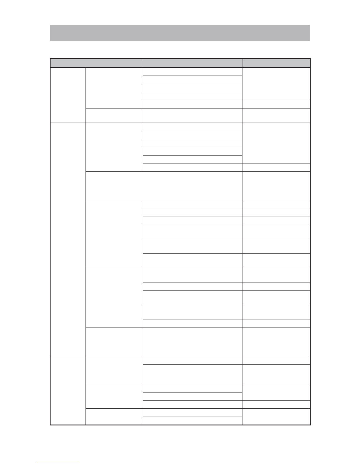
1. Troubleshooting and correction
Trouble Cause Corrective action
Starter
handle
cannot be
pulled.
The crank shaft does
not rotate.
Faulty piston ring
Disassemble and
replace.
Seized piston and cylinder
Faulty crank shaft bearings
Magneto rotor contact with ignition coil
Clogging of dirt in starter pawl Clean.
The recoil starter
does not rotate.
Broken recoil starter Inspect and replace.
Startup is
impossible.
No compression
Faulty piston ring
Replace.
Worn piston
Expired oil seal service life
Worn cylinder
Defective sealing of the packing
Decompression valve trouble
Clean or replace.
Short-circuited due to foreign matter between the spark plug
electrodes.
Remove foreign matter:
In case of frequent
occurrence, replace the
spark plug and clean.
No spark
Stop switch not at startup position Adjust to startup position.
Dirty or faulty spark plug
Clean or replace.
Improperly connected plug cap
Inspect and replace.
Disconnected or improperly connected
high voltage cord
Repair or replace.
Disconnected or faulty ignition coil
ass’y
Replace.
Large gap between the magneto rotor
circumference and ignition coil ass’y
Adjust.
The spark plug does
not become wet with
fuel after repeated
starting operation.
No fuel in the fuel tank
Add properly mixed fuel
(25:1 to 50:1).
Clogged fuel filter Clean or replace.
Faulty fuel pipe
Adjust, replace or
connect.
Faulty vent hole (tank cap inside plug)
on the fuel tank
Replace.
Faulty carburetor ass’y Adjust, clean or replace.
The spark plug is wet
due to excessive fuel
supplied.
Pulling the starter handle several
times with the choke button at the
“startup” position
Dry the spark plug.
Remove residual fuel
from inside the cylinder
and crank case.
Idling stops
although
startup is
possible.
Weak spark
Dirty or faulty spark plug Clean or replace.
Improper gap between the magneto
rotor circumference and ignition coil
ass’y
Adjust.
Low compression
Worn piston ring
Replace.
Expired oil seal service life
Decompression valve trouble Clean or replace.
Good spark and
compression
Revolutions too low for idling
Adjust.
Poorly adjusted carburetor ass’y
TROUBLESHOOTING GUIDE
Page 3
-2-
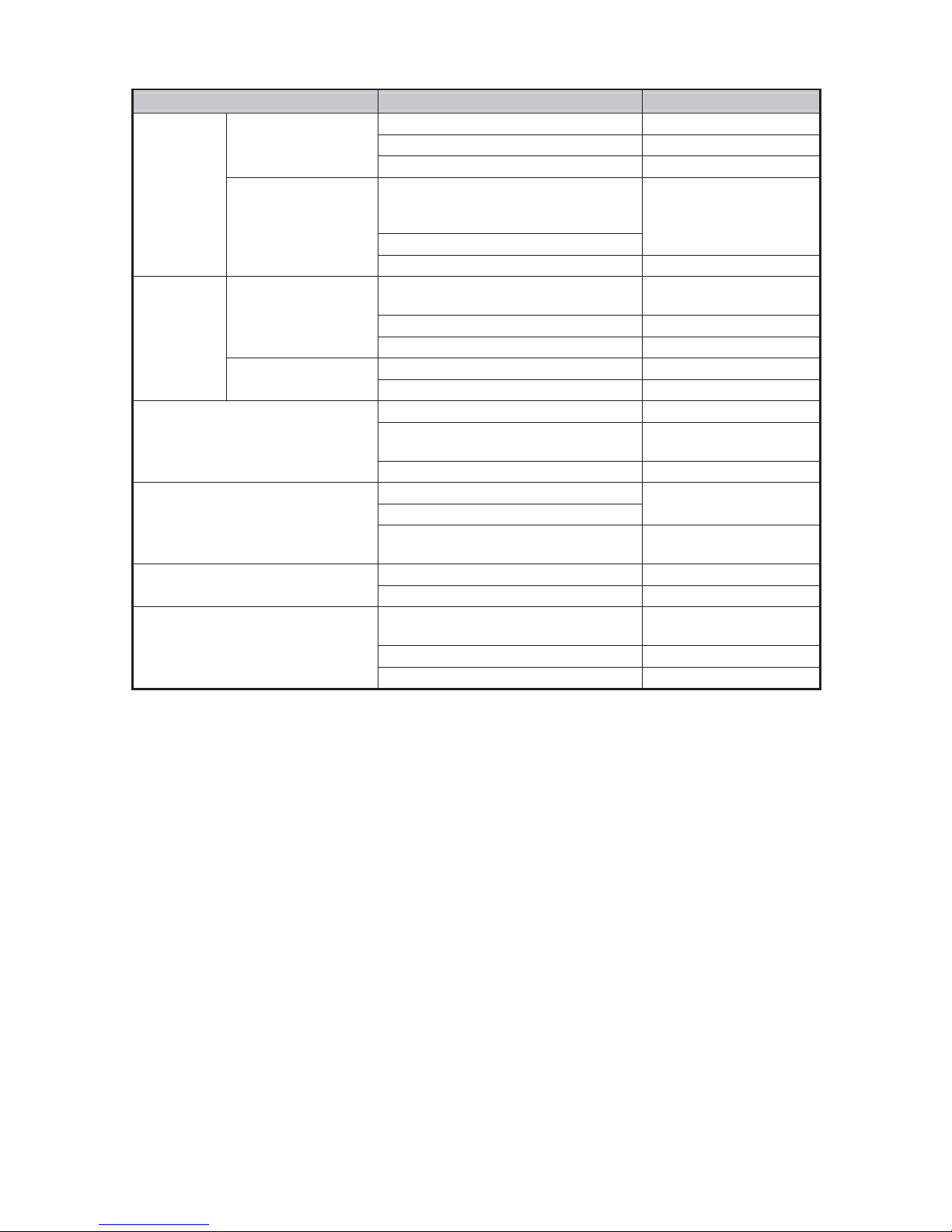
Trouble Cause Corrective action
Starts, but
when
accelerating
…
The engine stalls.
Clogged fuel filter Clean or replace.
Insufficient warm-up Warm up.
Poorly adjusted carburetor ass’y
Adjust.
Poor acceleration;
no increase in
revolutions
Clogged cylinder vent passage,
exhaust port and/or carbon-clogged
muffler
Clean.
Clogged air cleaner
Poorly adjusted carburetor ass’y Adjust, clean or replace.
Starts, but
…
Fluctuating
revolutions at high
speed
Dirt-clogged high-speed fuel line of the
carburetor ass’y
Clean.
Defective sealing of the packing Replace.
Faulty carburetor ass’y Adjust, clean or replace.
Excessive fuel
consumption
Clogged air cleaner Clean.
Poorly adjusted carburetor ass’y Adjust.
Abnormal vibration
Improper wheel mounting Mount properly.
Loose tightening of handle and other
parts
Check and firmly tighten
the loose parts.
Bent or broken wheel Replace with a new one.
Engine is running, but the wheel
hardly moves or is slow.
Loose belt
Adjust belt tension.
High belt tension
Belt disengaged from pulley
Firmly engage belt with
pulley.
Blunt cutting
Loose belt Adjust belt tension.
Worn-out wheel Replace with a new one.
No water supply from water
supplier
Loose connection of joint with faucet
Firmly connect both
parts.
Clogged joint Clean.
Hose of 14 mm or less in bore Replace.
Page 4
-3-
This section describes repair, focusing on portions requiring frequent repair. See the TROUBLESHOOTI NG
GUIDE in the previous section as the context for the following descriptions.
1. Precautions on maintenance, inspection and repair
• The fuel used readily ignites; therefore, never bring the product near a flame.
• Use new gaskets at reassembly.
• Prior to disassembly for repair, rem ove the fuel into separate containers, and allow the tool to cool down.
• During repair, startup or running, use adequate care for portions posing the risk of burn injury or electric
shock, such as hot areas including the muffler, high voltage cord, and spark plug.
• Before running the tool with the cut-off wheel attached, make sure that there are no other people nearby.
• Ensure proper ventilation when performing repair in a small room or other p oorly ventilated space.
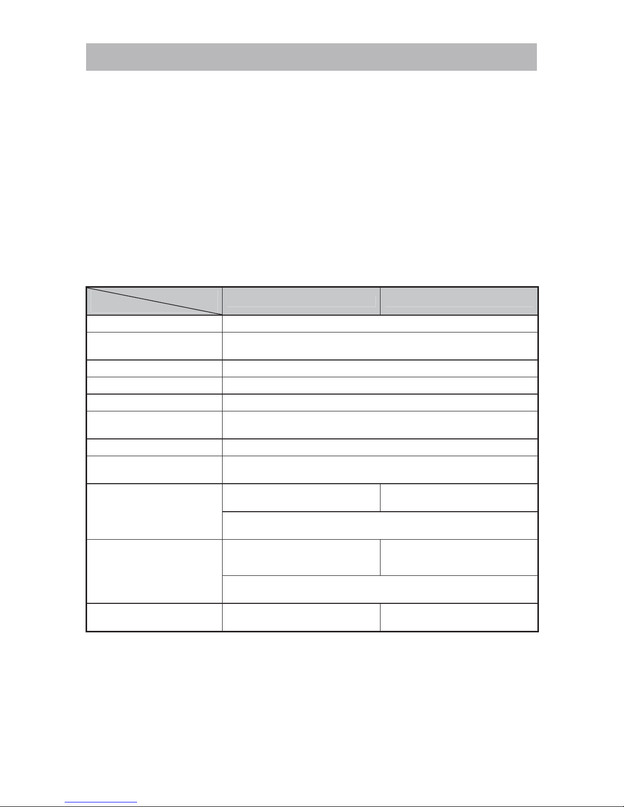
2. Inspection criteria for each section and consumable parts
Model
Item
CM 75EAP CM 75EBP
Idling revolutions 2,500 ± 200 min-1
No-load maximum revolutions
(with cut-off wheel)
9,800 ± 400 min
-1
Clutch engagement 3,800 ± 300 min-1
Spindle revolutions 4,050 ± 150 min-1
Accelerating performance Smooth acceleration
Gap between magneto rotor
and ignition coil ass’y
0.2 to 0.4 mm
Spark plug NGK BPMR7A
Gap between spark plug
electrodes
0.6 to 0.7 mm
Diamond cutter dimensions
305 mm in outside dia.
20 mm in hole dia.
355 mm in outside dia.
20 mm in hole dia.
(A diamond cutter of 25.4 mm in hole dia. is available
when using the accessory adapter collar.)
Cut-off wheel dimensions
305 mm in outside dia.
20 mm in hole dia.
3.5 mm in thickness
355 mm in outside dia.
20 mm in hole dia.
4.0 mm in thickness
(A cut-off wheel of 25.4 mm in hole dia. is available
when using the accessory adapter collar)
Max. circumferential speed of
cut-off wheel
80 m/s 100 m/s
* This engine cutter controls the maximum speed to 9,800 ± 400 min-1 in order to prevent the cut-off wheel
from breaking. Therefore, the pulse-count type of t achometer used for detecting ignition plug firing pulses
cannot measure maximum speed. Use one of the following methods to measure maximum speed:
• Use a tachometer of the electromagnetic induction type for detecting the movement of magnetic steel in
the magneto rotor.
• Use a stroboscope or similar instrument to measure the cut-off wheel rotation (spindle speed). Make a
safety check before running the cut-off wheel, and be very careful to avoid injury.
REPAIR GUIDE
Page 5
-4-
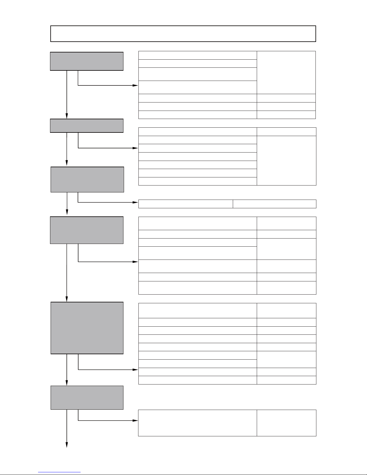
Broken piston ring
Replace.
Seized piston or cylinder
Seized or broken needle bearing of the crank
shaft
Seized or broken ball bearing of the crank
shaft
Magneto rotor contact with ignition coil Adjust.
Broken recoil starter Inspect/replace.
Clogging of dirt in starter pawl Clean.
Faulty piston ring Clean/replace.
Worn piston ring
Replace.
Worn piston
Worn or broken oil seal
Worn cylinder
Defective sealing of the packing
Decompression valve trouble
Ignition failure due to contaminant Clean (Remove contaminants.)
Stop switch not at startup position
Set to startup
position.
Dirty or faulty spark plug Clean/inspect.
Improperly connected plug cap
Inspect/replace.
Disconnected or improperly connected high
voltage cord and other wiring
Ground connection of high voltage cord and
other wiring
Inspect.
Disconnected or faulty ignition coil
Replace.
Improper gap between magneto rotor
circumference and ignition coil
Adjust.
No fuel in fuel tank
Add properly mixed
fuel (25:1 to 50:1).
Clogged fuel filter Clean/replace.
Bent fuel pipe Adjust.
Cracked fuel pipe Replace.
Disconnected fuel pipe Connect.
Faulty tank vent hole (tank cap inside plug)
Replace.
Faulty pump diaphragm of carburetor ass’y
Dirt-clogged carburetor ass’y Clean.
Poorly adjusted carburetor ass’y Adjust.
Pulling the starter handle several times with
the choke button at the “startup” position
Dry the spark plug.
Remove residual fuel
from cylinder and
crank case.
Repair flowchart
Pull the starter handle.
Is pulling possible?
Remove the spark plug to
check for sparks.
Are sparks generated?
Is there compression?
Return the spark plug
and plug cap to the
original positions, and
then perform proper
startup operation.
Is the tip of the spark plug
wet with fuel?
Is the spark plug wet due
to excessive supply of
fuel?
No
Yes
Yes
Yes
Yes
Yes
Is there any foreign
matter between the spark
plug electrodes?
No
Yes
No
No
No
No
Page 6
-5-
Dirty or faulty spark plug Clean/replace.
Improper gap between magneto rotor
circumference and ignition coil
Adjust.
Worn piston ring
Replace.
Expired oil seal service life
Decompression valve trouble
Clean/replace.
Revolutions low for idling
Adjust.
Poorly adjusted carburetor ass’y
Revolutions low for idling
Adjust.
Poorly adjusted carburetor ass’y
Defective sealing of the packing Replace.
Revolutions too high for idling
Adjust.
Poorly adjusted carburetor ass’y
Worn or faulty clutch Inspect/replace.
Clogged fuel filter
Clean/replace.
Inadequate warm-up, especially in cold
weather
Warm up.
Poorly adjusted carburetor ass’y
Adjust.
Clogged cylinder vent passage, exhaust port
or carbon-clogged muffler
Clean.
Clogged air cleaner
Poorly adjusted carburetor ass’y
Adjust.
Faulty carburetor ass’y pump diaphragm
Replace.
Dirt-clogged carburetor ass’y
Clean.
Dirt-clogged high-speed fuel line of the
carburetor ass’y
Clean.
Air intake from the packing section Inspect.
Faulty carburetor ass’y pump diaphragm Replace.
Poorly adjusted carburetor ass’y Adjust.
Revolutions low for idling
Adjust.
Poorly adjusted carburetor ass’y
Clogged air cleaner Clean.
Poorly adjusted carburetor ass’y Adjust.
Does the engine stop when
rapidly decelerating from
high speed?
Yes
No
Yes
Does the engine stop by
pulling the throttle lever?
No
Does the speed increase
by pulling the throttle lever?
Do revolutions fluctuate
during acceleration?
Tilt the tool during idling.
Does the engine stop?
Does the cut-off wheel
rotate during idling?
Start the tool and set to
idling mode.
Does the engine stop?
Is fuel consumption
excessive?
Yes
No
Yes
Yes
No
Yes
Yes
No
No
No
No
Yes
Page 7
-6-
Improper mounting of cut-off wheel Mount it adequately.
Loose tightening of handle and other parts
Firmly tighten the
loose parts.
Bent or broken cut-off wheel Replace.
Loose belt Adjust belt tension.
High belt tension Adjust belt tension.
Belt disengaged from pulley Engage adequately.
Poor connection of joint with faucet Connect.
Clogged joint Clean.
Hose of 14 mm or less in bore Replace.
Is there abnormal
vibration?
Is water supplied from the
water supplier?
Does the cut-off wheel
rotate?
No
Yes
Yes
No
No
Page 8
-7-
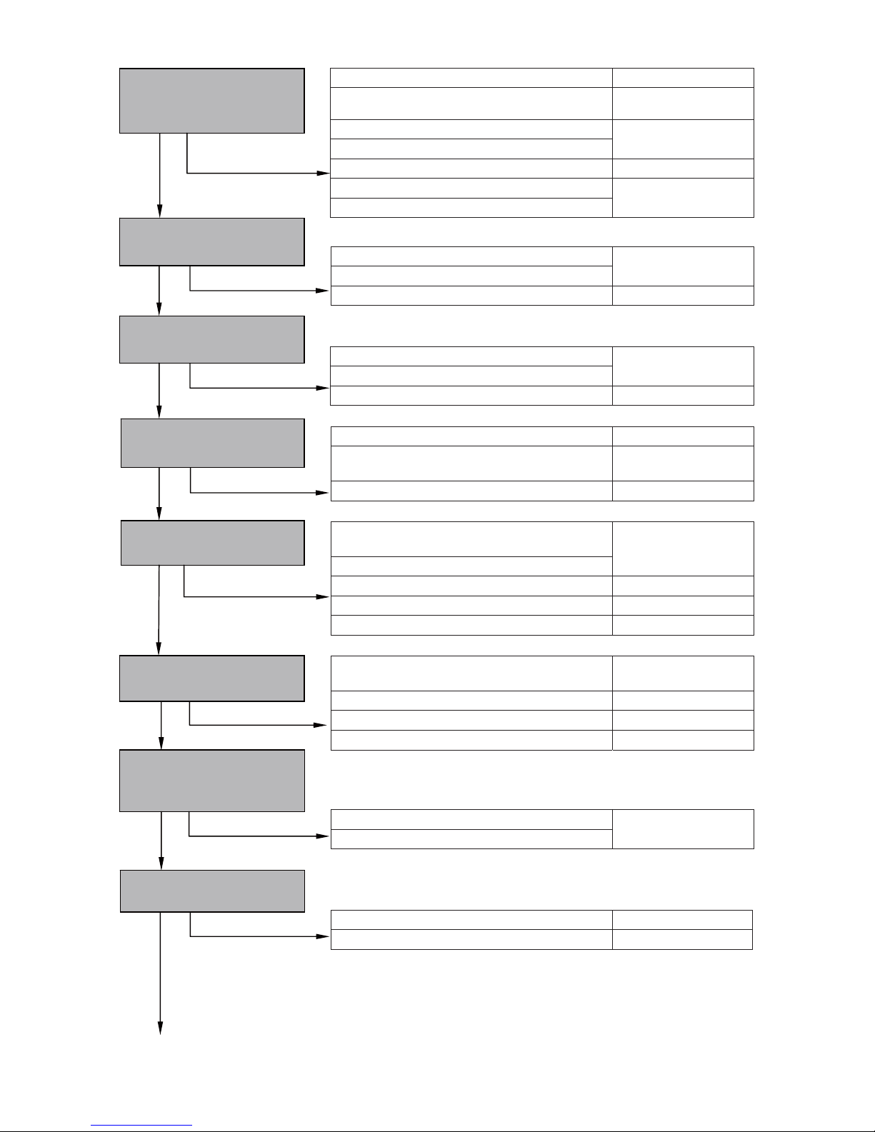
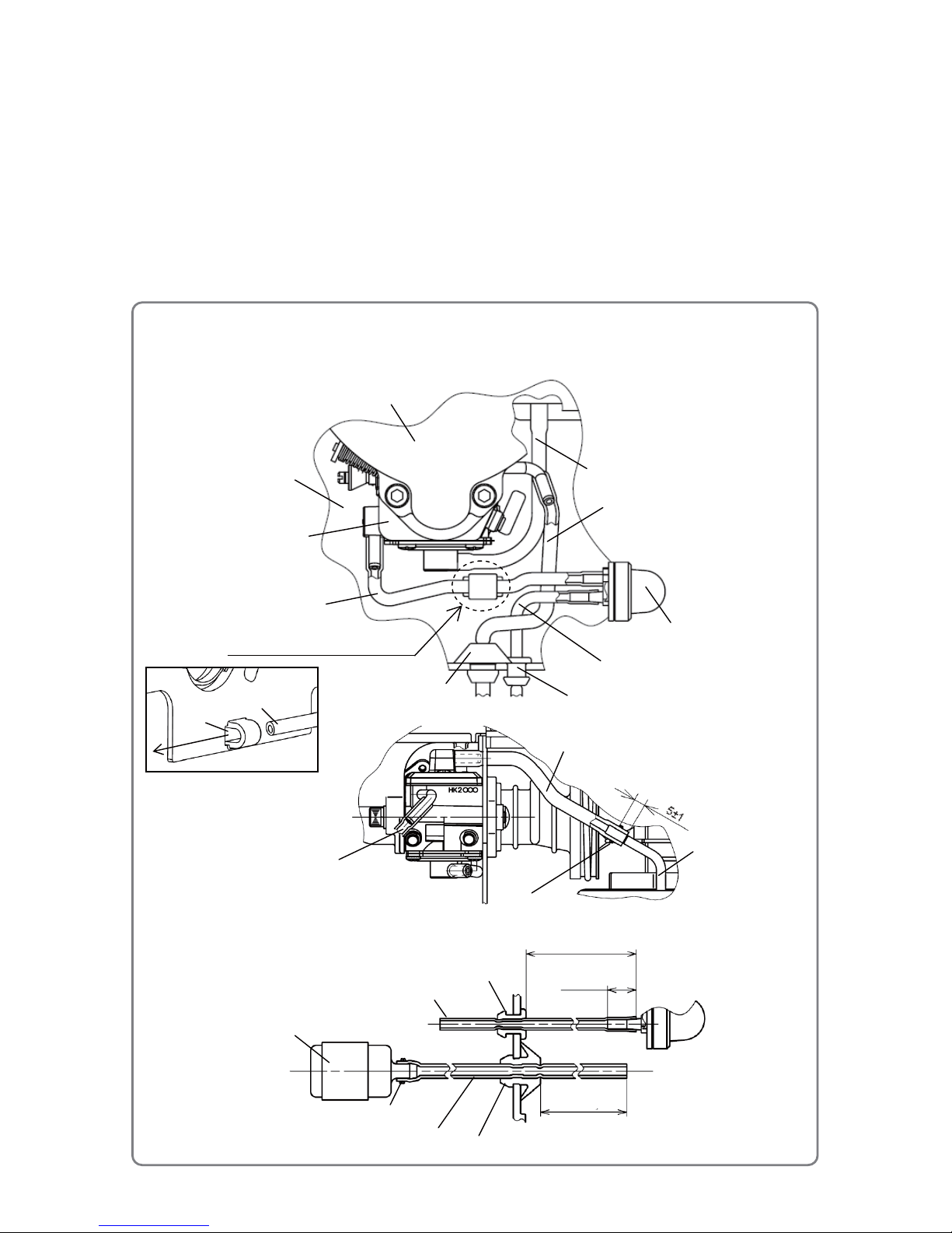
• Spark plug
• Checking for sparks
High voltage cord
Ignited sparks
[142]
Plug cap
Metallic portion of the engine
[Bold] numbers in the descriptions below correspond to item numbers in the Parts List and exploded
assembly diagram for the Models CM 75EAP and CM 75EBP.
WARNING: Always stop the engine prior to disassembly or when replacing the cut-off wheel.
1. Checking for sparks of the spark plug
CAUTION:
• Be careful not to touch the metallic portion of Spark
Plug Ass’y BPMR7A [142] when pulling the starter
handle; otherwise, you run the risk of electric shock.
• Carefully wipe off any fuel around the plug to avoid a
sudden flash of fire.
(1) Remove Spark Plug Ass’y BPMR7A [142] from the Cylinder
[146]. Use a wire brush to clean off carbon deposits on the
electrodes of Spark Plug Ass’y BPMR7A [142], as needed.
Adjust the gap between the electrodes if necessary. Use a
cloth to wipe off any fuel on the electrodes. Remove fuel left
in the Cylinder [146], Crank Case (A) [6], and Crank Case
(B) [44] by following the procedure below.
(a) Remove the Spark Plug Ass’y BPMR7A [142] from the
Cylinder [146].
(b) Open the choke (with the Choke button [191] pushed in)
and set the Stop Switch [196] to the stop position.
(c) Open the throttle by pulling the Throttle Lever [134].
(d) Pull the starter handle several times.
(2) Insert Spark Plug Ass’y BPMR7A [142] into the Plug Cap
Cord [24] and place the electrodes in contact with the
metallic portion of the engine. Under these conditions, set
the Stop Switch [196] to the startup position and pull the
starter handle.
(3) When the above steps are all completed normally, the electrodes of Spark Plug Ass’y BPMR7A [142]
should make a snapping sound to generate sparks.
2. Adjustment of the carburetor
(1) Use the idle adjust screw to adjust the carburetor.
• Use this screw to adjust the revolutions at idling. T urning the
screw clockwise increases engine revolutions; turning it
counterclockwise decreases engine revolutions.
(2) Standard setting of the carburetor
• 2,500 ± 200 min
-1
(3) Fine adjustment
• Idling adjustment
(a) Adjust the idling revoluti ons after the engine is fully
warmed up. (Tip on warm-up: Let the engine idle for one
minute in half-throttled status.)
(b) Use the idle adjust screw to set revolutions so that the cut-off wheel does not start rotating while
the engine runs stably.
(c) Set idling revolutions between 2,300 and 2,700 min
-1
by using the idle adjust screw. (Adjust to
approx. 2,500 min
-1
.)
Inspection and repair procedures
Gap between
electrodes
(0.6 to 0.7 mm)
Remove carbon here.
• Idle adjust screw
Idle adjust screw
Revolutions
decrease.
Revolutions
increase.
Page 9
-8-
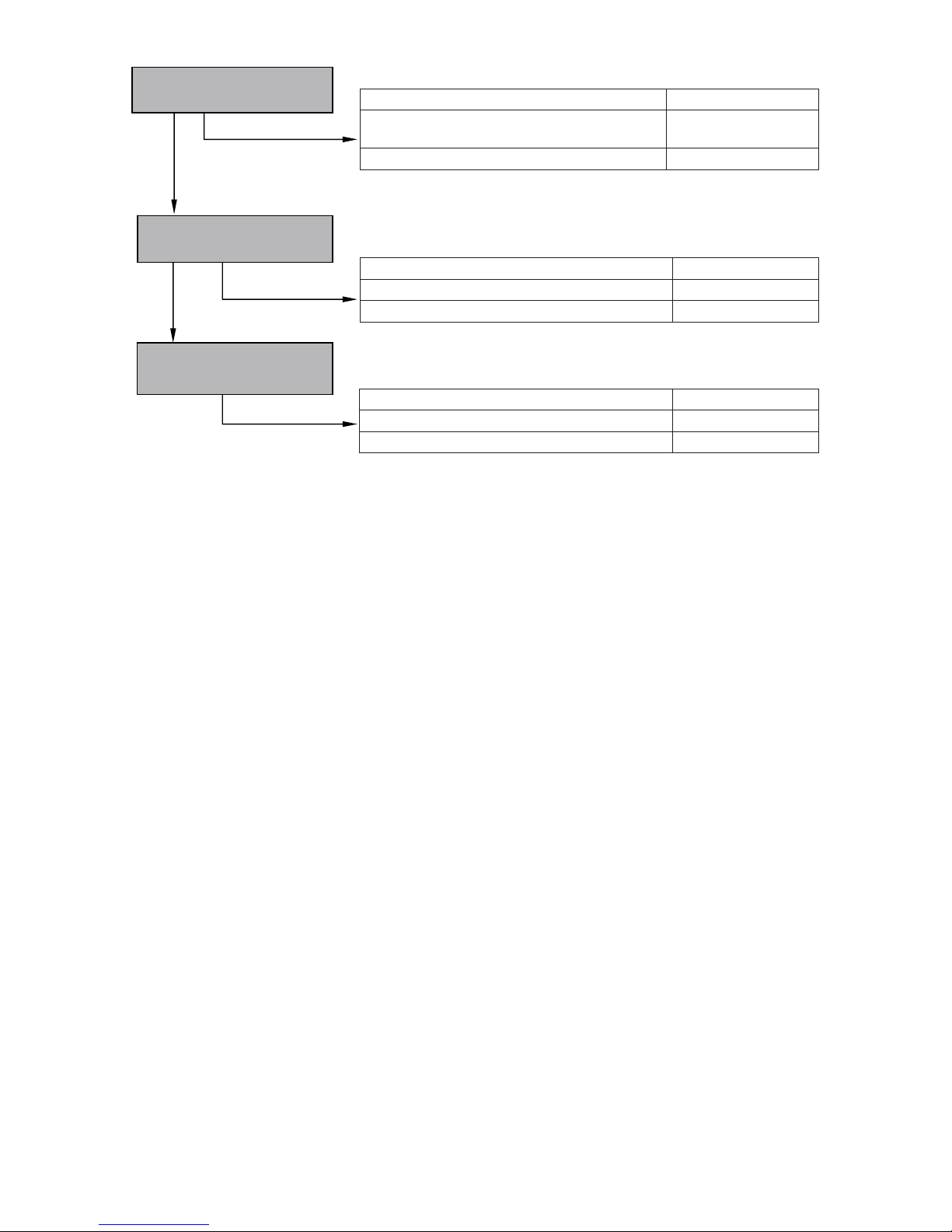
1. Disassembly and reassembly of the cleaner
[Tool required]
• Hex. bar wrench (4 mm)
(1) Disassembly
• Loosen the Cleaner Knob [184], remove Cleaner Box
(B) [187], and then take out the Pre Filter [182].
• Loosen the four Set Bolts M5 x 25 [10] by using a hex.
bar wrench (4 mm) and remove Cleaner Box (A) [189].
• Remove the Paper Filter [193] and Nylon Filter [194].
NOTE: Be careful not to let any dust get into the
engine when removing the filter.
• Remove the Rubber Rope [188] and two Bearing
Locks [190] from Cleaner Box (A) [189].
(2) Filter cleaning
• Pat the Pre Filter [182] or apply compressed air to it to
remove dust. If the filter is very contaminated, wash it
with soap and water, and then fully dry it.
• Apply compressed air to the Nylon Filter [194] in order
to remove dust.
• Pat the Paper Filter [193] or apply compressed air
from the bottom of the paper filter to remove dust.
NOTE: Never wash the Paper Filter [193].
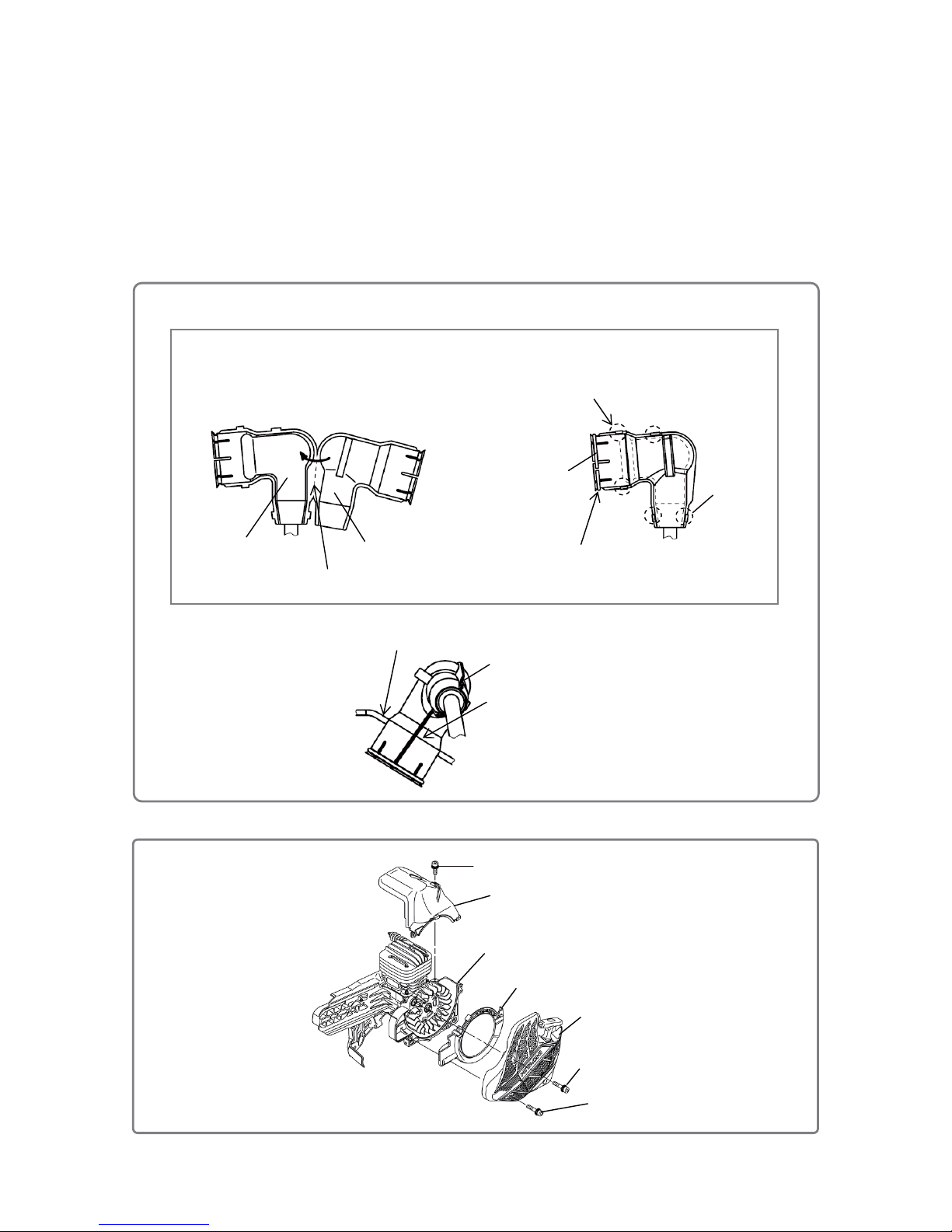
(3) Reassembly
Reassembly can be conducted by reversing the disassembly procedure. However, special attention
should be given to the following items.
• Insert the slit portion of the Choke Rod Rubber [192] into Cleaner Box (A) [189].
For details, see “3.
Disassembly and reassembly of the carburetor ass'y.”
• Assemble the Rubber Rope [188] with one end in cont act with the rib of Cleaner Box (A) [189] and the
other end aligned to the tip of the arrow mark.
Disassembly and reassembly
• Cleaner
[10]
[194]
[182]
[193]
[187]
[189]
[184]
[188]
Bottom
Apply air here.
• Rubber rope and bearing lock
[188]
[189]
[
190
]
Rear side
Rib
Arrow mark
Assemble the Rubber Rope
[188] with one end in
contact with the rib and the
other end aligned to the tip
of the arrow mark.
• Paper filter
[189]
Page 10
-9-
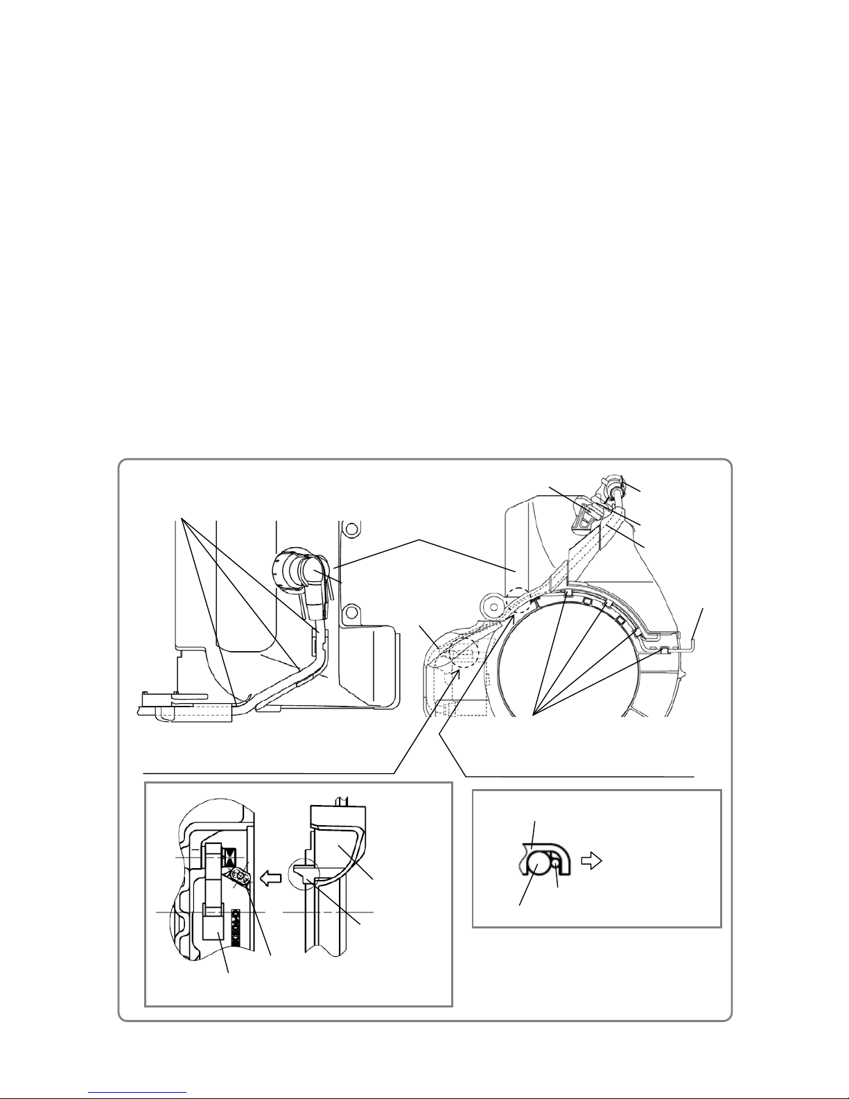
• Cord installation
2. Disassembly and reassembly of the recoil starter and cylinder
[Tools required]
• Hex. bar wrench (4 mm)
• Long-nose pliers
(1) Disassembly
• Pull out and remove the plug cap and Shield Cover [25] from Spark Plug Ass'y BPMR7A [142].
•
Loosen the three Set Bolts M5 x 25 [10] and one Set Bolt M5 [9] by using a hex. bar wrench (4 mm),
and then remove the Recoil Starter [8] and Fan Guide [7].
• Loosen the two Bolts M5 x 16 [45] by using a hex. bar wrench (4 mm), and then remove the Cylinder
Cover [136].
• Remove the Shield Cover Ring [26] from the Shield Cover [25] by using long-nose pliers.
• Use long-nose pliers to open the five caulked portions of the Shield Cover [25] and then remove the
Shield Cover [25] from the plug cap.
NOTE: The Shield Cover [25] and Shield Cover Ring [26] are not mounted on the Models
CM 75EAP and CM 75EBP for North America.
(2) Reassembly
Reassembly can be conducted by reversing the disassembly procedure. However, special attention
should be given to the following items.
• Do not reuse the Shield Cover [25].
• Mount the Shield Cover [25] on the plug cap according to the figure on the next page.
Assemble the high-voltage cord and Cord [21]
as shown in sectional diagram below.
High-voltage cord
Plug cap
[21]
Run the high-voltage cord in the groove of the Cylinder Cover [136].
Put the Cord [21] in pawls of the
Fan Guide
[7]
for reassembly.
[25]
[136]
[7]
[142]
[136]
[21]
High-voltage cord
Do not get any other part caught between the cord
terminal and terminal retaining rib of the Fan Guide [7].
Cord terminal
[23]
[7]
Terminal retaining rib
To the Recoil Starter [8]
[25]
Page 11
-10-
• Shield cover
• Recoil starter
• Align the line of the Shield Cover [25] to ±0.5 mm from the top of the Cylinder Cover [136] when
inserting the plug cap and Shield Cover [25] into the Spark Plug A ss'y BPMR7A [142].
• Put the Cord [21] in the pawls of the Fan Guide [7] for reassembly.
• Put the high-voltage cord of the Ignition Coil Ass'y [23] in the groove of the Cylinder Cover [136] and
Fan Guide [7] for reassembly.
• Do not get any other part caught between the cord terminal and the terminal retaining rib of the Fan
Guide [7].
• For easier reassembly of the Recoil Starter [8], put the Recoil Starter [8] on its mounting position, pull
the starter handle, and then return it into position.
1. Put the plug cap on the Shield Cover [25]
and fold the Shield Cover [25] into two.
[25]
Bend here.
Plug cap
2. Bend and caulk five tabs of the Shield Cover [25]
by using the long-nose pliers.
3. Mount the Shield Cover Ring [26] by using
long-nose pliers.
[26]
• Shield cover mounting method
Caulk here.
Top of the Cylinder Cover [136]
[25]
Align the line of the Shield Cover [25] to ±0.5 mm
from the top of the Cylinder Cover [136].
[136]
[6]
[7]
[8]
[10]
[45]
[9]
Page 12
-11-
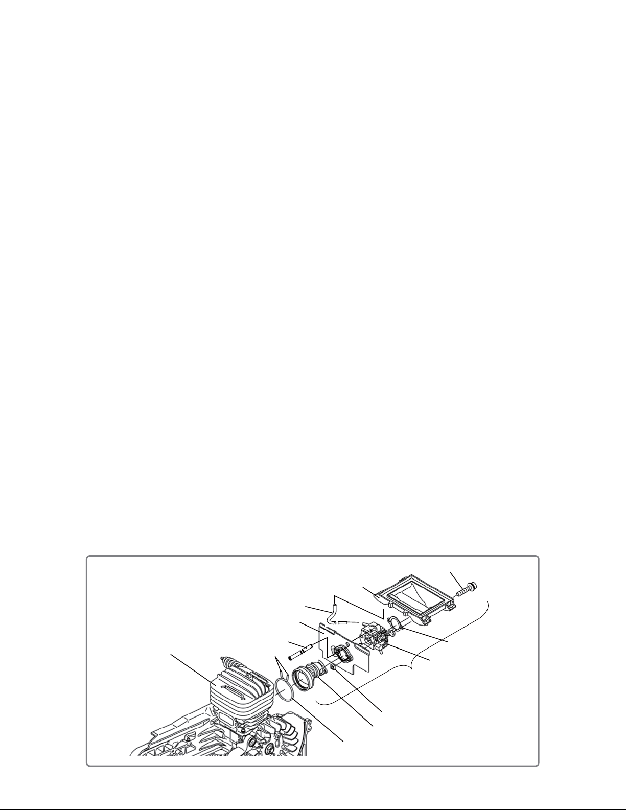
• Carburetor ass’y
3. Disassembly and reassembly of the carburetor ass'y
[Tools required]
• Hex. bar wrench (4 mm)
• Pliers
(1) Disassembly
• Clamp both ends of the Insulator Clip [147] with pliers. The Insulator Clip [147] opens wider. Remove
the Insulator Clip [147] from the groove of the Carburetor Insulator [149] and move it toward the
Insulator Plate [148].
• Pull out the Carburetor Insulator [149] from the Cylinder [146]. Be careful not to break the insulator.
• Remove the Choke Button [191] and Choke Rod Rubber [192] from Carburetor Ass'y (C3M) [151].
• Lift up the Carburetor Bracket [181] and remove the Throttle Rod [135] from Carburetor Ass'y (C3M)
[151] and the Throttle Lever [134].
• Remove the Fuel Pipes [105] [137] from Carburetor Ass'y (C3M) [151].
• Remove Fuel Pipe (FKM) [150] from the elbow joint.
• Loosen the two Bolts M5 x 55 [195] by using a hex. bar wrench (4 mm), and then remove the
Carburetor Insulator [149], Insulator Plate [148], two Square Nuts (B) M5 [167], Carburetor Ass'y
(C3M) [151], Carburetor Packing [180], and Carburetor Bracket [181].
• Remove the Fuel Pipe [166] from Carburetor Ass'y (C3M) [151] and the Carburetor Bracket [181].
• Remove Fuel Pipe (FKM) [150] from Carburetor Ass'y (C3M) [151].
(2) Reassembly
Reassembly can be conducted by reversing the disassembly procedure. However, special attention
should be given to the following items.
• Subassemble the parts of the Carburetor Insulator [149] as shown in the figure below before mounti ng
the Carburetor Insulator [149] on the Cylinder [146]. Make sure the throttle valve and choke valve of
Carburetor Ass'y (C3M) [151] move smoothly after subassembly.
• Fit the lip portion of the Carburetor Insulator [149] along the groove of the Insulator Plate [148] when
mounting the Carburetor Insulator [149] on the Insulator Plate [148].
• Be careful not to bend the Fuel Pipes [105] [137] [150] [166]. For details, see “4. Connection of the
fuel pipes.”
• For reassembly of the Throttle Rod [135], first insert its tip into the throttle valve of Carburetor Ass'y
(C3M) [151], and then fit the rod to the Throttle Lever [134] while pulling the Throttle Lever [134].
• Apply 0.1 to 0.2 g of Alvania Grease RL3 to the sliding portions of the Choke Button [191] and Choke
Rod Rubber [192] (in the range of 16 to 20 mm from the end of the Choke Button [191]).
• Orient the Choke Button [191] and Choke Rod Rubber [192] correctly. Insert Cleaner Box (A) [189] into
the slit portion of the Choke Rod Rubber [192] when reassembling Cleaner Box (A) [189].
[195]
[149]
[147]
[148]
[151]
[180]
[181]
[146]
Ends
[167]
Subassemble and mount to the cylinder.
[166]
[150]
Page 13
-12-
• Throttle rod and choke button
• Firmly fit the protrusion of the inner surface of the Carburetor Insulator [149] into the groove of
the Cylinder [146] when mounting the Carburetor Insulator [149] on the Cylinder [146].
• Fit the Insulator Clip [147] into the groove of the Carburetor Insulator [149] when reassembling the
clip.
[135]
[191]
[192]
[134]
[151]
Throttle valve
Choke valve
[192]
Apply 0.1 to 0.2 g of Alvania Grease RL3 to the sliding porti ons
of the Choke Button [191] and Choke Rod Rubber [192].
NOTE: Orient the Choke Button [191] and
Choke Rod Rubber [192] correctly.
Fit Cleaner Box (A) [189] to the slit portion
when mounting Cleaner Box (A) [189].
18±2
Page 14
-13-
4. Connection of the fuel pipes
The fuel pipes are connected as shown below.
(1) Insert each fuel pipe firmly down to the root of the mating pipe.
(2) Be careful not to bend or twist any fuel pipe.
(3) Be careful not to let any fuel pipe get pinched by other parts.
(4) Position the Clip [138] about 4 to 6 mm away from the end of the pipe near the elbow joint of Fuel Pipe
(FKM) [150].
(5) The projections of Fuel Pipe (Pink) [106] and the Fuel Pipe [137] from the Return Grommet [113] and
Fuel Grommet [112] should be 100 to 10 5 mm and 70 to 75 mm, respectively.
NOTE: Do not mix up the pipes to be inserted into the Priming Pump Comp. [104].
• Fuel pipe connection
[104]
[151]
[106]
[137]
[148]
NOTE: Do not mix up the positions of
the Fuel Pipe [137] and Fuel
Pipe [105].
Thread the Fuel Pipe [105]
throu
g
h the hole as shown below.
[105]
[181]
[166]
[137]
Hole
[105]
[138]
[113]
[112]
[150] (Insert up to the scale line of the elbow joint.)
Elbow joint
[106]
[137]
[113]
[112]
[139]
[138]
7 or more
100
+5
0
70
+5
0
Page 15
-14-
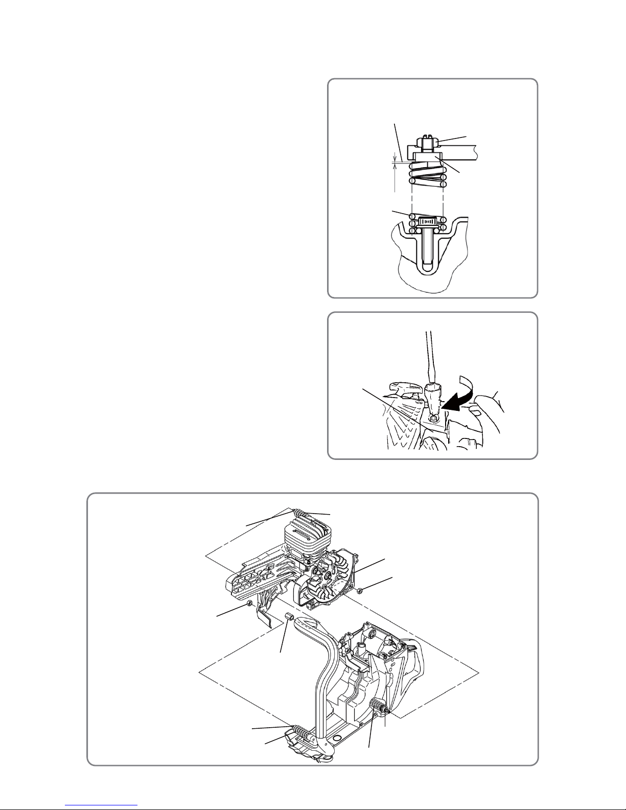
5. Disassembly and reassembly of the crank case and rear handle
[Tools required]
• Flat-blade screwdriver
• Double-head wrench 10 x 19 mm
• 10 mm socket torque wrench
(1) Disassembly
• Fit the tip of a flat-blade screwdriver into the slot
of the bolt portion of the Spring Holders [60] [140]
to prevent bolt rotation, and then remove the Nut
M6 [47] and Long Nut M6 [116] by using a
double-head wrench 10 x 19 mm or similar tool.
(2) Reassembly
Reassembly can be conducted by reversing the
disassembly procedure. However, special
attention should be given to the following items.
• Mount the Spring Holders [60] [140] so that the
first loop is above that of the Antivibration Springs
[120] [141] [201]. (See the upper-right figure.)
• Apply 0.1 to 0.3 g of Chemiseal L-391 (Chemitech
Inc.) to the bolt portions of the Spring Hol ders [60]
[140] or the female threads of Nut M6 [47] and
Long Nut M6 [116].
• Fit the tip of a flat-blade screwdriver into the slot
of the bolt portion of the Spring Holders [60] [140]
to prevent bolt rotation as shown on the right, and
firmly tighten the Nut M6 [47] and Long Nut M6
[116] without turning the Spring Holders [60]
[140] together by using a double-head wrench 10
x 19 mm or similar tool.
Then tighten the Nut M6 [47] and Long Nut M6 [116] at a specified torque of 5.5±0.5 N•m {56±5
kgf•cm} by using a 10 mm socket torque wrench to check the torque.
• Reassembly of the antivibration coil spring ass'y
[60] [140]
[47] [116]
Up to 1 mm
The Antivibration Springs [120][141][201] must not
exceed this surface of the Spring Holders [60][140].
[120] [141] [201]
• Tightening of the nut M6
[47] [116]
• Rear handle and crank case
[6]
[47]
[47]
[116]
[60]
[201]
[141]
[120]
[60]
[140]
Page 16

-15-
• Clutch
If the Spring Holders [60] [140] turn together with Nut M6 [47] and Long Nut M6 [116] at less than the
specified torque, retighten the nuts by using a flat-blade screwdriver and a double-head wrench 10 x 19
mm.
6. Disassembly and reassembly of the clutch
[Tools required]
• Hex. bar wrench (4 mm)
• Socket wrench (19 mm)
(1) Disassembly
• Loosen the three Set Bolts M5 x 25 [10] by using a hex. bar wrench (4 mm), and then remove the
Clutch Cover [35].
• Insert a socket wrench (19 mm) into the Clutch [36], turn it clockwise using an impact screwdriver or
similar tool, remove the Clutch [36], and then remove the Clutch Flange [37], Felt Packing [38], Clutch
Housing [39], Shim T0.2 [42], and Bolt Washer M12 [43].
NOTE: The Clutch [36] screwed into the Crank Shaft [1] is left-ha nd threa ded. Do not remov e S p ark
Plug Ass'y BPMR7A [142] from the Cylinder [146]. Set the Decomp. [144] to the OFF
position (pulled to the near side ).
(2) Reassembly
Reassembly can be conducted by reversing the disassembly procedure. However, special attention
should be given to the following items.
• Degrease the female threads of the Clutch [36] and the threads of the Crank Shaft [1] before
mounting the Clutch [36].
• The Hitachi 14.4-V impact screwdriver can apply specified torque to the Clutch [36] by tightening for
about one second.
NOTE: • Do not overtighten.
• Perform a test run after reassembly and make sure the Clutch [36] does not become
loose.
• Retighten the Flange Nut M8 [20] of the Magneto Rotor [14] after mounting the Clutch
[36] to prevent loosening.
[41] (Press-fit in the Clutch Housing [39].)
[14]
[20]
[36]
[37]
[38]
[39]
[42]
[43]
[10]
[35]
Page 17

-16-
• Magneto rotor
7. Disassembly and reassembly of the magneto rotor
[Tools required]
• Jig J-363 (Code No. 6694822) (8 x 120 handle)
• Jig J-357 (Code No. 6695737) (Center bolt)
• Jig J-356 (Code No. 6695736) (Rotor extractor comp.)
• Jig J-365 (Code No. 6695739) (Shoulder bolt 5 mm)
• Socket wrenches (10 mm and 13 mm)
• Hook spanner wrench (for ĭ120 to 130)
(1) Disassembly
• Remove the two Step Bolts [19] by using a socket wrench
(10 mm). Remove the two Shims [18], two Starter Pawls
[17], two Starter Pawl Springs [15], and two Washers 0.8
[16].
• Remove the Flange Nut M8 [20] by using a socket wrench
(13 mm).
• Put the thread end of the Crank Shaft [1] and the top
surface of a commercial M8 nut at the same level, and turn
the jig J-363 (8 x 120 handle) in the arrow direction to tighten the jig J-357 (center bolt). You can now
remove the Magneto Rotor [14].
(2) Reassembly
Reassembly can be conducted by reversing the disassembly procedure. However, special attention
should be given to the following items.
• Degrease the tapered portion of the Magneto Rotor [14] and the threaded and tapered portions of the
Crank Shaft [1] before mounting the Magneto Rotor [14].
• Adjust the gap between the Magneto Rotor [14] and Ignition Coil Ass'y [23] when either is
disassembled according to “8. Adjustment of gap between the magneto rotor and ignition coil ass'y.”
• Turn the Magneto Rotor [14] clockwise around the Crank Shaf t [1] for reassembly.
• Check the operation of the Starter Pawls [17] after reassembly.
• Lock the rotational movement of the Magneto Rotor [14] and then tighten Flange Nut M8 [20] at a
specified torque by using the hook spanner wrench (for ĭ120 to 130).
NOTE: • Hook the hook spanner wrench (for ĭ120 to 130) to the magnetic steel or counterweight
portion of the Magneto Rotor [14] for use.
• Retighten the Flange Nut M8 [20] of the Magneto Rotor [14] after mounting the Clutch
[36] to prevent loosening.
[15]
[16]
[17]
[18]
[19]
[20]
[1]
Hook spanner wrench (for ĭ120 to 130)
Hook the hook spanner wrench (for
ĭ120 to 130) to the magnetic steel or
counterweight portion for use.
[14]
ĭ124
• Removing the magneto rotor
J-363 (8 x 120 handle)
J-357 (Center bolt)
[14]
J-356
(Rotor extractor
comp.)
J-365
(
Shoulder bolt 5 mm)
Page 18

-17-
8. Adjustment of gap between the magneto rotor and ignition coil ass'y
(1) Loosen the two Bolts M4 x 18 [27] so as to
temporarily retain the Ignition Coil Ass'y [23].
(2) Insert a 0.3-mm thickness gauge into the
clearance between the Ignition Coil Ass'y [23]
and the periphery of the magnetic steel portion
of the Magneto Rotor [14].
(3) In this state, firmly tighten the two Bolts M4 x 18
[27].
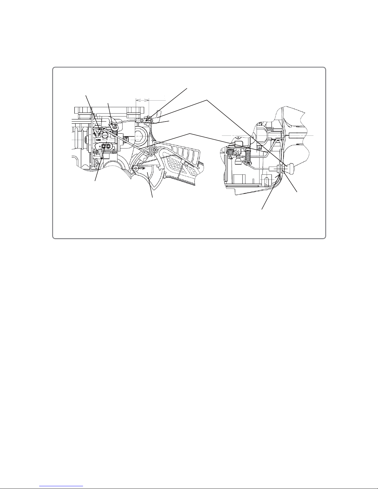
9. Electric wiring
Perform wiring according to the following figure.
(1) Connect the connector of the Cord [21] to the Ignition Coil Ass'y [23].
(2) Connect the Earth Cord [11] to Crank Case (A) [6] using the Bolt M4 x 10 [12].
(3) Fit the Stop Switch [196] to the Rear Handle Set [114] with the “1” mark on the left side.
(4) Connect the connectors of the Cord [21] and Eart h Cord [11] to the connectors of the S top Switch [196].
(5) Place the Switch Cover [197] on the Stop Switch [196].
NOTE: Do not get the Cord [21] and the high-voltage cord pinched by other parts.
• Electric wiring
[27]
[6]
[142]
[11]
[146]
[12]
[196]
[197]
[21]
[23]
[114]
High-voltage cord
[22]
• Adjustment of gap between the magneto rotor and ignition coil
ass’y
[14]
0.2 to 0.4 mm
0.2 to 0.4 mm
[27]
[23]
Page 19

-18-
• Water supplier
10. Disassembly and reassembly of the muffler
[Tools required]
• Hex. bar wrench (5 mm)
• Phillips screwdriver
(1) Disassembly
• Remove the two Bolts M6 x 20 [126] and two Bolts
M6 x 50 [123] by using a hex. bar wrench (5 mm),
and then remove the Muffler [124] and Heat
Protection Plate [125].
• Remove the two Machine Screws M4 x 12 [127] by
using a Phillips screwdriver, and then remove the
Exhaust Gasket [129] and Exhaust Pipe [128].
(2) Cleaning of exhaust ports
• Use steel wire to remove carbon dust in the
exhaust ports of the Cylinder [146] and Muffler
[124], as well as in the Exhaust Pipe [128], and
then use compressed air to blow the parts clean.
NOTE: Be careful not to let any carbon dust into the cylinder, and be careful not to damage the
Heat Protection Plate [125].
(3) Reassembly
Reassembly can be conducted by reversing the disassembly procedure. However, special attention
should be given to the following items.
• Degrease the threaded holes of the Cylinder [146], Crank Case (A) [6], and Crank Case (B) [44]
before remounting the Muffler [124].
• Temporarily secure the Muffler [124] with the two Bolts M6 x 20 [126] and two Bolts M6 x 50 [123],
and then firmly tighten all the bolts.
• Do not reuse the Bolts M6 x 20 [126] and Bolts M6 x 50 [123].
11. Disassembly and reassembly of the water supplier
[Tools required]
• Hex. bar wrench (5 mm)
•
Socket wrench (19 mm)
(1) Disassembly
• Loosen the Lock Nut [75] and pull out the Water Supply Hose [76]. Loosen the Water Supply
Connector [174] by using a socket wrench (19 mm) and remove the Valve [176] and Coupler [177]
from the Mounting Plate [175].
(2) Reassembly
Reassembly can be conducted by reversing the disassembly procedure. However, special attention
should be given to the following items.
• Be careful not to bend the Water Supply Hose [76].
• Firmly insert the Water Supply Hose
[76]
into the Water Supply Connector
[174]
until it contacts the end.
• Gradually increase the tightening torque of the Coupler [177] to prevent radial protrusion of the O-ring .
[129]
• Muffler
[124]
[125]
[123]
[126]
[128]
[127]
[6]
[44]
[146]
[76]
[75]
[174]
[175]
[176]
[177]
[118]
O-ring
Page 20

-19-
• Cylinder
12. Disassembly and reassembly of the cylinder
[Tools required]
• Hex. bar wrench (5 mm)
• Socket wrenches (13 mm and 19 mm)
(1) Disassembly
•
Remove Spark Plug Ass'y BPMR7A [142] by using a socket wrench (19 mm).
• Remove the four Bolts M6 x 25 [168] using a hex. bar wrench (5 mm), and then remove the Cylinder
[146].
•
Remove the Decomp. [144] and Decomp Cap [143] by using a socket wrench (13 mm).
(2) Reassembly
Reassembly can be conducted by reversing the disassembly procedure. However, special attention
should be given to the following items.
• Completely wipe off all liquid packing (ThreeBond 1207C) from the matching surfaces of the Cylinder
[146], Crank Case (A) [6], and Crank Case (B) [44], and from the surface of Cylinder Packing (C)
[169]. Be careful not to damage the matching surfaces.
• Never reuse the Bolts M6 x 25 [168]. Replace the bolts with new ones.
• Degrease the threaded holes of Crank Case (A) [6] and Crank Case (B) [44] before reassembling the
Cylinder [146].
• Do not reverse the orientation of Cylinder Packing (C) [169]. (Mount it according to the shape of the
exhaust port.)
• Be careful not to damage the cylindrical surface of the Cylinder [146] when disassembled. Remove
carbon dust from the exhaust port and combustion chamber, and then clean both parts with gasoline.
• Be careful not to let any dust enter the Cylinder [146] from its ports when reassembling the Cylinder
[146].
• Apply a thin coating of two-cycle oil to the cylindrical surface of the Cylinder [146] and the peripheral
surface of Piston (51.5) [172] when reassembling the Cylinder [146].
• Apply liquid packing (ThreeBond 1207C) to the entire faces on both sides of Cylinder Packing (C)
[169]. Fully degrease the mating faces before applying the grease.
[169]
[6]
[149]
[147]
[148]
[168]
[169]
[44]
[144]
[146]
[142]
[172]
[143]
Apply liquid packing
(ThreeBond 1207C) to the
entire faces
(
both sides).
Page 21

-20-
• Disassembly of the piston
Hex. socket
hd. bolt M6
Pin extracting bolt
Jig J-381
13. Disassembly and reassembly of the piston and piston rings
[Tools required]
• Long-nose pliers
• Jig J-381 (Code No. 6600412) (Piston pin extractor ass’y)
• Hex. socket hd. bolt M6
• Round bar about 11.8 mm in diameter (Borer 12 mm in diameter, etc.)
(1) Disassembly
• Remove the two Cir Clips [171] by using long-nose
pliers.
• Fit an extra hex. socket hd. bolt M6 to the pushing
end of the Piston Pin [173]. Turn the pin extracting
bolt of the jig J-381 to push out the Piston Pin [173].
NOTE: Be careful not to damage the Piston
(51.5) [172].
• Pull out the two Piston Rings [170] by widening
their closed gap portions.
NOTE: Do not widen the gap too much. Doing
so runs the risk of breaking the ring.
(2) Reassembly
• Be careful not to damage the peripheral surface of the Piston (51.5) [172] when disassembled.
Remove carbon dust from the top of the Piston (51.5) [172] and clean the piston with gasoline.
• If the two Piston Rings [170] do not move smoothly, remove carbon dust from the ring grooves of the
Piston (51.5) [172] and the two Piston Rings [170], and fully clean the parts with gasoline.
• Follow the steps below to insert the Piston Pin [173]. See the following figure “Reassembly of the
piston.”
(a) Mount the jig J-381 on the Piston (51.5) [172] and fit an extra hex. socket hd. bolt M6 into the
pushing end of the Piston Pin [173].
(b) Mount Needle Bearing (A) [2] on the connecting rod small end and cover it with the Piston (51.5)
[172]. Align the triangular arrow on top of the Piston (51.5) [172] with the direction of the exhaust
port of the Cylinder [146]. Insert a round bar about 1 1.8 mm in diameter (a bo rer 12 mm in diameter,
etc.) into the Piston (51.5) [172] opposite the side where the Piston Pin [173] is inserted, in order to
prevent Needle Bearing (A) [2] from becoming misaligned.
(c) With a round bar 11.8 mm in diameter inserted, turn the pin extracting bolt of the jig J-381 cl ockwise
and push in the bolt just before the circlip mounting groove of the Piston (51.5) [172], being careful
not to slant the Piston Pin [173].
• Do not reuse the two Cir Clips [171].
• Fit the tips of the two Cir Clips [171] into the grooves of the Piston (51.5) [172] by using long-nose
pliers, and fit the entire clips into the grooves by turning them along the grooves.
• Align the openings of the two Piston Rings [170] to the knock pins of the Piston (51.5 ) [172].
• Apply a small quantity of two-cycle oil to Needle Bearing (A) [2] after mounting the Piston (51.5)
[172].
Page 22

-21-
• Reassembly of the piston
• Piston and piston rings
[170]
[172]
[173]
[171]
[2]
Pin extracting bolt Round bar 11.8 mm in diameter
(borer 12 mm in diameter, etc.)
Circlip mounting groove
[2]
Hex. socket hd. bolt M6
[173]
Connecting rod small end
Connecting rod small end
Page 23

-22-
• Crank case
14. Disassembly and reassembly of the crank case
[Tool required]
• Hex. bar wrench (4 mm)
(1) Disassembly
• Remove the four Bolts M5 [13] by using a hex. bar wrench (4 mm). You can now remove Crank Case
(A) [6], Crank Case (B) [44], and the Crank Shaft [1].
• To disassemble Ball Bearing 6202C3 [4] and the Oil Seal [5], push both from the Oil Seal [5] side.
(2) Reassembly
Reassembly can be conducted by reversing the disassembly procedure. However, special attention
should be given to the following items.
• Do not reuse the Oil Seal [5] and Ball Bearing 6202C3 [4] when disassembled from Crank Case (A)
[6] and Crank Case (B) [44].
• Do not reuse the Crank Case Packing [3].
• Do not reuse the four Bolts M5 [13].
• Apply 50 to 100 mg of Piloknock Universal No. 0 (JX Nippon Oil & Energy) between the lips of the Oil
Seal [5].
• Carefully clean the Crank Shaft [1] by using gasoline before mounting.
• Before mounting Crank Case (A) [6] and Crank Case (B) [44], fully degrease their threaded holes.
Mount them without pinching Fuel Pipe (FKM) [150].
• Assemble the Crank Case Packing [3] by correctly aligning its hole position without any deviation.
After matching Crank Case (A) [6] and Crank Case (B) [44], check their outer peripheries and make
sure the Crank Case Packing [3] is along the Crank Case mating face.
• Cut off the protrusion of the Crank Case Packing [3] at the mating face of the Cylinder [146] after
mounting.
NOTE: Do not break the Crank Case Packing [3] when cutting it.
[1]
[3]
[4]
[5]
[6]
[44]
[5]
[4]
[13]
[46]
[45]
Page 24

-23-
15. Disassembly and reassembly of the arm and wheel guard
[Tools required]
• Socket wrench (13 mm)
• Hex. bar wrench (4 mm)
• Long-nose pliers
(1) Disassembly
• Loosen the Flange Nut M8 [20] by using a socket wrench (13 mm), and then remove the Arm [63] and
Arm Cover [34] from Crank Case (B) [44].
• Insert a hex. bar wrench (4 mm) into Pulley (B) [51] to lock its rotation. Loosen the Bolt M8 [48] by
using a socket wrench (13 mm). Remove the Flange Washer [87] and outside Wheel Washer [85].
Pull out the Spindle Collar [86] with long -nose pliers and remove the inside Wheel Washer [85].
• Insert a hex. bar wrench (4 mm) into Pulley (B) [51] to lock its rotation. Loosen the Bolt M8 [48] by
using a socket wrench (13 mm). Remove the Washer 8.1 x 30 [49] and Pulley (B) [51]. Loosen the
three Bolts M5 (S) [56] by using a hex. bar wrench (4 mm) and remove the Wheel Guard [80] from the
Arm [63].
(2) Reassembly
Reassembly can be conducted by reversing the disassembly procedure. However, special attention
should be given to the following items.
• Press-fit the Spindle Collar [86] to the Spindle [84] until it contacts the end surface. Be careful not to
bend the Spindle Collar [86]. Orient the Spindle Collar [86] so that its smaller diameter side faces the
Arm [63].
• When inserting Pulley (B) [51] and the Wheel Washer [85] into the Spindle [84], align the width across
flats of Pulley (B) [51] and Wheel Wa sher [85] with those of the Spindle [84].
• When tightening the two Bolts M8 [48], insert a hex. bar wrench (4 mm) into the holes of Pulley (B)
[51] and the Arm [63] to prevent from rotating.
• Run the Water Supply Hose [76] between the Arm [63] and Wheel Guard [80]. Do not bend the hose.
• Apply 0.15 to 0.25 g of Chemiseal L-391 to the Bolt M8 [48] (pulley side) after degreasing the thread
portion with part cleaner.
• Arm and wheel guard
[44]
[34]
[80]
[83]
[85]
[87]
[48]
[86]
[84]
[63]
[57]
[56]
[48]
*Apply Chemiseal L-391.
[49]
[51]
[20]
Insert a hex. bar wrench (4 mm) into the holes of Pulley
(B) [51] and the Arm [63] to prevent rotation.
[51]
[63]
Hex. bar
wrench
(4 mm)
[59]
[40]
[76]
[68]
Run the Water Supply Hose [76]
among the four Bolts M5 x 12 [68]
as shown in the figure.
Page 25

-24-
16. Disassembly and reassembly of the arm
[Tools required]
• Hex. bar wrench (4 mm)
• Pliers
• Round bar about 15 mm in diameter
• Round bar about 17 mm in diameter
(1) Disassembly
• Remove the Retaining Ring [52] by using pliers.
• Push a round bar about 15 mm in diameter towards the Spindle [84] from the Arm Plate [67] side to
remove a set of the Spindle [84], two Ball Bearings 6203DD [53], and BB Collar [54] from the Arm
[63].
• Remove the two Ball Bearings 6203DD [53] and BB Collar [54] from the Spindle [84].
• Remove the Felt [55] from the Arm [63].
• Loosen the Bolt M5 x 12 [62] by using a hex. bar wrench (4 mm), and remove the Stopper Holder [64]
and Stopper Rubber [65].
• Loosen the four Bolts M5 x 12 [68] by using a hex. bar wrench (4 mm), and remove the Arm Plate [67]
and the four Collars [66].
(2) Reassembly
Reassembly can be conducted by reversing the disassembly procedure. However, special attention
should be given to the following items.
• Do not reuse the removed Ball Bearings 6203DD [53] (2 pcs.).
• Mount the Felt [55], Ball Bearing 6203DD [53] (felt side), BB Collar [54], Ball Bearing 6203DD [53]
(retaining ring side), Spindle [84], and Retaining Ring [52] to the Arm [63] in this order.
NOTE:
• Push the outer ring of Ball Bearing 6203DD [53] to press-fit it into place.
• When press-fitting the Ball Bearing 6203DD [53] (retaining ring side), insert a round bar
about 17 mm in diameter into the BB Collar [54] and Ball Bearing 6203DD [53] (felt side) to
prevent the BB Collar [54] from becoming misaligned.
• When press-fitting the Ball Bearing 6203DD [53] (retaining ring side), immediately stop
press-fitting when the ball bearing contacts the BB Collar [54]. Note that excessive
press-fitting will apply shearing force to the inner and outer rings of the ball bearing.
• Hold the inner ring of the Ball Bearing 6203DD [53] (retaining ring side) when press-fitting
the Spindle [84].
• Firmly fit the Retaining Ring [52] into the ring groove of the Arm [63].
• Arm
[84]
[65]
[64]
[63]
[55]
[53]
[54]
[53]
[52]
[62]
[67]
[68]
[66]
[58]
Page 26

-25-
17. Disassembly and reassembly of the wheel guard
[Tools required]
• Hex. bar wrench (4 mm)
• Socket wrench (13 mm)
• Flat-blade screwdriver
• Long-nose pliers
(1) Disassembly
• Loosen the two Set Bolts M5 x 16 [71] by using a hex. bar wrench (4 mm), and then remove Handle
(W) [72].
• Remove the two Plates (A) [69] and two Dampers (A) [70] by using a flat-blade screwdriver.
• Loosen the three Lock Nuts [75] and remove the Water Supply Hoses [50] [7 6].
• Loosen the two Cap Nuts [73] by using a socket wrench (13 mm), and then remove Water Supply
Joint (A) [82] and Water Supply Joint (B) [74].
(2) Reassembly
Reassembly can be conducted by reversing the disassembly procedure. However, special attention
should be given to the following items.
• Insert the Water Supply Hoses [50] [76] until they contact the end faces.
• To secure Water Supply Joint (A) [82] and Water Supply Joint (B) [74], insert the Nozzl e Bolt [77] into
the hole of the Wheel Guard [80] by using long-nose pliers and tighten the Cap Nut [73] from the
opposite side.
• Do not mix up the mounting positions of Handle (W) [72], Water Supply Joint (A) [82], Water Supply
Joint (B) [74], and the S t opper Rubber [65].
NOTE: Note that the Models CM 75EAP and CM 75EBP have different Stopper Rubber [65]
mounting positions.
Page 27

-26-
• Wheel guard
[82]
[73]
[76]
[80]
[69]
[70]
[72]
[71]
[75]
[74]
[70]
[77]
[65]
[79]
[78]
Do not mix up the mounting positions of Handle (W) [72], Water Supply
Joint (A) [82], Water Supply Joint (B) [74], and the Stopper Rubber [65].
NOTE: Note that the Models CM 75EAP and CM 75EBP have different
Stopper Rubber [65] mounting positions.
[50]
[50]
[80]
[72]
[65]
[69]
[74]
[50]
Model CM 75EAP
Model CM 75EBP
Page 28

-27-
18. Disassembly and reassembly of the front handle
[Tools required]
• Hex. bar wrenches (4 mm and 5 mm)
• Phillips screwdriver
(1) Disassembly
• Loosen the two Tapping Screws D4 x 16 [109] by using a Phillips screwdriver, and remove Grip End
(A) [145] and Grip End (B) [122].
• Loosen the Bolt M6 x 20 [119] by using a hex. bar wrench (5 mm), and remove the Antivibration Spring
[120].
• Loosen the two Bolts M5 [207] by using a hex. bar wrench (4 mm), and remove the Front Adapter
[121], Front Handle [117], Lower Guard [202], Front Foot Holder [204], and Front Foot Plate [206].
• Remove the two Front Foot Rubbers [205] from the Front Foot Holder [204].
• Loosen the four Bolts M5 x 12 [62] by using a hex. bar wrench (4 mm), and remove the Muffler Guard
[203].
(2) Reassembly
Reassembly can be conducted by reversing the disassembly procedure. However, special attention
should be given to the following items.
• Fit the pawls of the Front Foot Holder [204] into the grooves of the two Front Foot Rubbers [205].
• Front handle
[203]
[58]
[62]
[207]
[206]
[205]
[145]
[117]
[119]
[122]
[204]
[120]
[121]
[109]
[202]
[205]
[204]
Fit the pawls of the Front Foot Holder [204] into
the grooves of the two Front Foot Rubbers [205].
Page 29

-28-
19. Disassembly and reassembly of the rear handle
[Tools required]
• Hex. bar wrench (5 mm)
• Phillips screwdriver
• Jig J-382 (Code No. 6600413) (Inner cap jig ass’y)
• Round bar about 2.5 mm in diameter
• Pliers
(1) Disassembly
• Loosen the seven Tapping Screws D6 [118] by usi ng a hex. bar wrench (5 mm ), and remo ve the Front
Handle [117], Lower Guard [202], and Antivibration Spring [201].
• Loosen the two Tapping Screws D4 x 16 [109] by using a Phillips screwdriver, and remove the Rear
Foot [200].
• Loosen one Tapping Screw D4 x 16 [109] by using a Phillips screwdriver , and remove the Air Vent Cap
[110] and Inner Cap (B) [111].
• Loosen the Tapping Screw D4 x 25 [107] by using a Phillips screwdriver, and remove the Trigger
Lockout [131] and Trigger Lockout Collar [130]. Push the Trigger Lockout [131] towards the Throttle
Lever [134] and pull it out to remove. For details, see the figure on the next page.
NOTE: The Rear Handle Set [114] cannot be disassembled into left and right parts as shown
below even by loosening the three Tapping Screws D4 x 16 [109] that secure the grip
portion, because the fuel tank is welded to the Rear Handle Set [114].
• Rear handle
[133]
[109]
[199]
[107]
[110]
[111]
[131]
[114]
[130]
[132]
[134]
[103]
[198]
[179]
[
178
]
[200]
[201]
[202]
[118]
[118]
[117]
[118]
[109]
[109]
Page 30

-29-
• Remove the four Square Nuts M5 [103] and Grommet [178] from the Rear Handle Set [114].
• Push in Needle Pin D3 [132] with a round bar about 2.5 mm in diameter from outside of the Rear
Handle Set [114], and then remove the Throttle Lever [134] and Throttle Lever Spring [133].
• Pull out the Throttle Lock Pin Cap [199] with pliers, and remove the Throttle Lock Pin Spring [198] and
Throttle Lock Pin [179].
(2) Reassembly
Reassembly can be conducted by reversing the disassembly procedure. However, special attention
should be given to the following items.
• Hook the hook portion of the Throttle Lever Spring [133] to the Throttle Lever [134].
• Press-fit Needle Pin D3 [132] down to a point that is 7 to 8 mm deep from the Rear Handle Set [114].
• Insert the Trigger Lockout Collar [130] into the Trigger Lockout [131], and then insert both parts into
the Rear Handle Set [114]. Temporarily push the Trigger Lockout [131] toward the Throttle Lever [134],
and then pull it back to adjust the position.
• Fit the Throttle Lever Spring [133] into the groove of the Trigger Lockout [131]. The Throttle Lever
Spring [133] must be positioned behind the Trigger Lockout [131] as shown below.
• Press-fit Inner Cap (B) [111] into the Rear Handle Set [114] by using the jig J-382 (inner cap jig (A)
and inner cap jig (B)). For details, see the figure on the next page.
• Throttle lever and trigger lockout
[131]
[134]
(1) (4)
Retaining rib
(2)
(5)
Disassembly and reassembly of the trigger
lockout
• Disassembly
(1) Push in the Trigger Lockout [131] toward
the Throttle Lever [134].
(2) Pull out the Trigger Lockout [131] while
keeping the retaining rib away from the
Rear Handle Set [114].
• Reassembly
(3) Insert the Trigger Lockout Collar [130] into
the Trigger Lockout [131].
(4) Push in the Trigger Lockout [131] toward
the Throttle Lever [134] with the Throttle
Lever Spring [133] positioned behind the
Trigger Lockout [131] as shown in the
lower-left figure.
(5) Insert the Trigger Lockout [131] while
keeping the retaining rib away from the
Rear Handle Set [114].
(6) Adjust the position of the Trigger Lockout
[131] as shown in the lower-left figure.
[114]
[130]
[133]
[131]
[114]
[132]
[134]
[134]
Hook the hook portion of the
Throttle Lever Sprin
g
[133] here.
Fit the Throttle Lever Spring
[133] into the groove.
The Throttle Lever Spring [133] must
be behind the Trigger Lockout [131].
[130]
Press-fit depth: 7.5±0.5
[114]
Page 31

-30-
• Press-fitting inner cap (B)
2. Set Inner Cap (B) [111] in inner cap jig (A).
3. Set the Rear Handle Set [114] to prevent
inner cap jig (A) from tilting.
4. Press-fit Inner Cap (B) [111] until it contacts
inner cap jig (A) using inner cap jig (B).
Inner cap jig (B)
Inner Cap (B) [111]
Rear Handle Set [114]
Inner cap jig (A)
1. Apply two-cycle oil.
Apply to the areas.
Page 32

-31-
Location Q’ty Part name Tightening torque
Recoil
starter
Recoil Starter Ass’y [8]
3
Set Bolt M5 x 25 [10]
4.4 to 7.4 N•m
{45 to 75 kgf•cm}
1
Set Bolt M5 [9]
Electrical
system
Ignition Coil Ass’y [23]
2
Bolt M4 x 18 [27]
3.0 to 4.0 N•m
{31 to 41 kgf•cm}
Spark Plug Ass’y BPMR7A
[142]
1
Spark Plug Ass’y BPMR7A [142]
25 to 30 N•m
{255 to 306 kgf•cm}
Earth Cord [11]
1
Bolt M4 x 10 [12]
3.0 to 4.0 N•m
{31 to 41 kgf•cm}
Carburetor
ass’y
Carburetor Ass’y (C3M) [151]
1
Screw (D) [152]
1.8 to 2.2 N•m
{18 to 23 kgf•cm}
1
Screw (E) [157]
0.7 to 0.8 N•m
{7 to 9 kgf•cm}
4
Set Screw (C) [165]
0.7 to 0.8 N•m
{7 to 9 kgf•cm}
Carburetor Ass’y (C3M) [151]
Carburetor Bracket [181]
2
Bolt M5 x 55 [195]
1.4 to 2.0 N•m
{14 to 20 kgf•cm}
Rear
handle
Antivibration Spring [201]
1
Tapping Screw D6 [118]
3.5 to 4.5 N•m
{36 to 46 kgf•cm}
Antivibration Spring [120]
1
Bolt M6 x 20 [119]
6.0 to 9.0 N•m
{61 to 92 kgf•cm}
Antivibration Spring [141]
1
Spring Holder [60]
1 each
Nut M6 [47]
5.0 to 6.0 N•m
{51 to 61 kgf•cm}
Spring Holder [140]
1
Long Nut M6 [116]
5.0 to 6.0 N•m
{51 to 61 kgf•cm}
Front Handle [117]
2
Tapping Screw D6 [118]
3.5 to 4.5 N•m
{36 to 46 kgf•cm}
2
Bolt M5 [207]
2.7 to 4.1 N•m
{28 to 42 kgf•cm}
Rear Handle Set [114]
5
Tapping Screw D4 x 16 [109]
1.5 to 2.5 N•m
{15 to 25 kgf•cm}
1
Tapping Screw D4 x 25 [107]
1.0 to 2.0 N•m
{10 to 20 kgf•cm}
Air Vent Cap [110]
1
Tapping Screw D4 x 16 [109]
1.3 to 1.7 N•m
{13 to 17 kgf•cm}
Lower Guard [202]
4
Tapping Screw D6 [118]
3.5 to 4.5 N•m
{36 to 46 kgf•cm}
Grip End (A) [145]
Grip End (B) [122]
2
Tapping Screw D4 x 16 [109]
1.5 to 2.5 N•m
{15 to 25 kgf•cm}
Clutch
Clutch Cover [35]
3
Set Bolt M5 x 25 [10]
4.4 to 7.4 N•m
{45 to 75 kgf•cm}
Clutch [36]
1
Clutch [36]
35 to 40 N•m
{357 to 408 kgf•cm}
Magneto
rotor
Magneto Rotor [14]
1
Flange Nut M8 [20]
(Retighten when the Clutch [36] is
assembled.)
26 to 29 N•m
{265 to 295 kgf•cm}
Sta rter Pawl [17]
1 each
Step Bolt [19]
5.9 to 6.9 N•m
{60 to 70 kgf•cm }
Tightening torque
Page 33

-32-
Location Q’ty Part name Tightening torque
Engine
Cylinder [146]
4
Bolt M6 x 25 [168]
9.0 to 10.0 N•m
{91 to 101 kgf•cm}
Decomp. [144]
1
Decomp. [144]
12 to 27 N•m
{122 to 275 kgf•cm}
Muffler [124]
2
Bolt M6 x 20 [126]
11.3 to 12.3 N•m
{115 to 125 kgf•cm }
2
Bolt M6 x 50 [123]
11.3 to 12.3 N•m
{115 to 125 kgf•cm}
Exhaust Pipe [128]
2
Machine Screw M4 x 12 [127]
1.6 to 2.0 N•m
{16 to 20 kgf•cm}
Crank Case (A) [6]
Crank Case (B) [44]
4
Bolt M5 [13]
5.0 to 6.0 N•m
{51 to 61 kgf•cm}
Arm
Arm Cover [34]
2
Flange Nut M8 [20]
7.8 to 11.8 N•m
{80 to 120 kgf•cm}
Pulley (B) [51]
1
Bolt M8 [48]
14 to 16 N•m
{143 to 163 kgf•cm}
Cut-off Wheel [505]
Diamond wheel
1
Bolt M8 [48]
20 N•m
{209 kgf•cm}
Wheel Guard [80]
3
Bolt M5 (S) [56]
4.4 to 7.4 N•m
{45 to 75 kgf•cm}
Stopper Rubber [65]
1
Bolt M5 x 12 [62]
4.4 to 7.4 N•m
{45 to 75 kgf•cm}
1
Bolt M5 x 12 [78]
4.4 to 7.4 N•m
{45 to 75 kgf•cm}
Handle (W) [72]
2
Set Bolt M5 x 16 [71]
2.5 to 3.5 N•m
{25 to 35 kgf•cm}
Arm Plate [67]
4
Bolt M5 x 12 [68]
3.5 to 4.5 N•m
{35.8 to 45.8 kgf•cm}
Chain Bar Bolt [61]
2
Chain Bar Bolt [61]
15.5 to 20.5 N•m
{158 to 209 kgf•cm}
Water
supplier
Water Supply Connector [174]
1
Water Supply Connector [174]
15 to 17 N•m
{153 to 173 kgf•cm}
Mounting Plate [175]
1
Tapping Screw D6 [118]
3.5 to 4.5 N•m
{36 to 46 kgf•cm}
Coupler [177]
1
Coupler [177]
1.0 to 2.0 N•m
{10 to 20 kgf•cm}
Water Supply Hose [50] [76]
4
Lock Nut [75]
Manual tightening until
it contacts the flange
Water Supply Joint (A) [82]
Water Supply Joint (B) [74]
1 each
Cap Nut [73]
1.5 to 2.1 N•m
{15 to 21 kgf•cm}
Others
Cylinder Cover [136]
2
Bolt M5 x 16 [45]
4.4 to 7.4 N•m
{45 to 75 kgf•cm}
Cleaner Box (A) [189]
4
Set Bolt M5 x 25 [10]
1.1 to 1.5 N•m
{11 to 15 kgf•cm}
Cleaner Box (B) [187]
1
Cleaner Knob [184]
Manual tightening
Tensioner Base [46]
1
Bolt M5 x 16 [45]
4.4 to 7.4 N•m
{45 to 75 kgf•cm}
Cover Plate [29]
1
Button Bolt M5 x 10 [28]
1.5 to 2.5 N•m
{15.4 to 25.4 kgf•cm}
Muffler Guard [203]
4
Bolt M5 x 12 [62]
4.4 to 7.4 N•m
{45 to 75 kgf•cm}
Page 34

-33-
1. Check the following before starting the engine.
• No fuel leakage is allowed.
• Confirm that the crank shaft rotates and there is compression when pulling the starter handle.
• Confirm that the starter handle can be pulled lightly when the decompression valve is set in the ON
position (push-in state).
• Perform priming ten times and then confirm that the priming pump is full of fuel.
2. Check the following after starting the engine.
• Confirm that the engine starts up by following the procedure below.
(1) Set the stop switch to the startup position.
(2) Pull the throttle lever while pushing the trigger lockout. Push the throttle lock pin to half-open the
throttle.
(3) Perform priming ten times.
(4) Keep pulling the choke button.
(5) Set the decompression valve in the ON position (push-in state).
(6) Pull the starter handle and check for initial ignition. As a guide, pull 3 to 5 times at ordinary
temperature (20°C). Increase the number of pulling times at low temperature.
(7) Push in the choke button.
(8) Set the decompression valve in the ON position (push-in state) again as combustion pressure
returns the valve automatically to the OFF position.
(9) Pull the starter handle to start the engine. As a guide, pull 2 or 3 times at ordinary temperature
(20°C). Increase the number of pulling times at low temperature.
(10) Lightly pull the throttle lever with the trigger lockout pressed. Confirm that half-throttle status is
canceled and the engine returns to idling.
• Make sure that the respective moving and rotating parts work smoothly without any abnormal noise.
• Adjust the carburetor. See “2. Adjustment of the carburetor” on page 7.
• Make sure that the cut-off wheel does not run while the engine is idling.
• Operate the throttle lever without gripping the trigger lockout, and make sure that engine revolutions do
not increase.
• Check both idling engine speed and no-load full engine speed with the cut-off wheel mounted.
• Make sure that the engine accelerates smoothly.
• Release the throttle lever and make sure that the engine idles.
• Allow the engine to idle, and then rapidly accelerate and decelerate the engine. Make sure that the
engine does not stop.
• Reset the stop switch to the stop position and make sure that the engine stops.
Confirmation after reassembly
Page 35

ENGINE
Model CM 75EAP
ENGINE CUTTER
LIST NO. F070
(E1)
2014 · 9 · 12
B
A
14
7
8
10
10
1
2
3
6
4
5
5
4
11
12
13
15
16
17
18
19
25
22
24
21
23
20
27
28
20
29
31
32
33
34
30
35
36
37
39
40
41
43
44
46
47
48
49
50
51
52
53
53
54
55
56
57
60
61
62
63
64
65
69
70
70
69
71
72
73
74
75
75
75
82
73
76
77
80
83
84
85
85
86
87
48
45
26
42
38
9
79
78
81
58
59
67
68
65
66
Page 36

CM 75EAP
- 2 -
9 - 14
B
C
C
D
D
E
E
F
F
A
75
58
178
47
60
101
102
103
103
104
105
106
107
111
110
109
112
113
114
130
131
116
117
118
118
118
118
119
120
119
121
122
123
125
124
126
127
128
129
139
138
137
132
133
134
135
140
136
141
144
145
146
142
147
66
150
148
149
166
168
167
169
170
171
172
173
171
174
175
176
177
191
192
193
194
195
181
180
179
196
197
198
199
200
201
202
205
205
206
207
204
501
502
109
109
45
109
151
152
153
154
155
156
157
159
160
161
158
162
163
165
10
10
182
184
185
187
188
189
190
164
62
203
504
503
505
143
108
115
183
186
138
Page 37

PART
S
CM 75EAP
DESCRIPTION REMARKS
1 6699801 CRANK SHAFT 1
2 6699803 NEEDLE BEARING (A) 1
3 6699800 CRANK CASE PACKING 1
4 6202C3 BALL BEARING 6202C3 2
5 6698914 OIL SEAL 2
6 6600364 CRANK CASE (A) 1 INCLUD.4,5
7 6699875 FAN GUIDE 1
8 6699876 RECOIL STARTER 1
9 6600374 SET BOLT M5 1
10 6699871 SET BOLT M5 X 25 10
11 6699813 EARTH CORD 1
12 949812 HEX. SOCKET HD. BOLT M4 X 10 (10 PCS.) 1
13 6600365 SEAL LOCK HEX. SOCKET HD. BOLT M5 4
14 6699808 MAGNETO ROTOR 1
15 6699810 STARTER PAWL SPRING 2
16 6696857 WASHER 0.8 2
17 6699811 STARTER PAWL 2
18 6696434 SHIM 2
19 6696878 STEP BOLT 2
20 6698581 FLANGE NUT M8 3
21 6699812 CORD 1
22 6698700 GLASS WASHER 2
23 6699809 IGNITION COIL ASS'Y 1 INCLUD.24
24 PLUG CAP CORD 1
* 25 6699814 SHIELD COVER 1 EXCEPT FOR USA
* 26 6600373 SHIELD COVER RING 1 EXCEPT FOR USA
27 6698388
HEX. SOCKET HD. BOLT (W/WASHERS) M4 X 18 2
28 6699909
SEAL LOCK HEX. SOCKET BUTTON BOLT M5 X 10 1
29 6699908 COVER PLATE 1
30 6699907 TENSIONER BOLT 1
31 6699904 TENSIONER PLATE 1
32 6699906 TENSIONER SPRING 1
33 6699905 TENSION NUT 1
34 6699903 ARM COVER 1
35 6699878 CLUTCH COVER 1
36 6699823 CLUTCH 1
37 6699822 CLUTCH FLANGE 1
38 301946 FELT PACKING 1
39 6699821 CLUTCH HOUSING 1
40 6699877 BELT 1
41 6001DD BALL BEARING 6001DDCMPS2L 2
42 6696946 SHIM T0.2 1
43 6685072 BOLT WASHER M12 1
44 6600366 CRANK CASE (B) 1 INCLUD.4,5
45 6699826
HEX. SOCKET HD. BOLT (W/WASHERS) M5 X 16 3
46 6699825 TENSIONER BASE 1
47 6698449 NUT M6 2
48 6699902 BOLT M8 2
49 6684924 WASHER 8.1 X 30 1
50 6699910 WATER SUPPLY HOSE 1
9 - 14 - 3 - *ALTERNATIVE PARTS
ITEM
NO.
NO.
USED
CODE NO.
Page 38

PART
S
CM 75EAP
DESCRIPTION REMARKS
51 6699899 PULLEY (B) 1
52 948391 RETAINING RING FOR D40 HOLE 1
53 6203DD BALL BEARING 6203DDCMPS2L 2
54 6699880 BB COLLAR 1
55 6699879 FELT 1
56 6699896 BOLT M5 (S) 3
57 6699895 WHEEL GUARD SPRING 3
58 949566 LOCK NUT M5 (10 PCS.) 8
59 949425 WASHER M6 (10 PCS.) 3
60 6699850 SPRING HOLDER 2
61 6699881 CHAIN BAR BOLT 2
62 6699176
HEX. SOCKET HD. BOLT (W/SP.WASHER) M5 X 12 5
63 6600367 ARM 1
64 6699883 STOPPER HOLDER 1
65 6600368 STOPPER RUBBER 2
66 6699866 COLLAR 6
67 6600396 ARM PLATE 1
68 6696836
HEX. SOCKET HD. BOLT M5 X 12 (PRECOAT) 4
69 6699885 PLATE (A) 2
70 6699886 DAMPER (A) 2
71 6699889 SET BOLT M5 X 16 2
72 6699888 HANDLE (W) 1
73 6699892 CAP NUT 2
74 6699891 WATER SUPPLY JOINT (B) 1
75 6699912 LOCK NUT 4
76 6699911 WATER SUPPLY HOSE 1
77 6699893 NOZZLE BOLT 2
78 996399
HEX. SOCKET HD. BOLT (W/FLANGE) M5 X 12 1
79 6600375 STOPPER HOLDER (B) 1
80 6699887 WHEEL GUARD (12") 1
81 6600376 WHEEL MARK LABEL (12") 1
82 6699890 WATER SUPPLY JOINT (A) 1
83 6699894 FLANGE (A) 1
84 6699882 SPINDLE 1
85 6699897 WHEEL WASHER 2
86 6699898 SPINDLE COLLAR 1
87 6699901 FLANGE WASHER 1
101 6600369 TANK CAP 1 INCLUD.102
102 6685179 TANK CAP PACKING 1
103 6699828 SQUARE NUT M5 4
104 6685139 PRIMING PUMP COMP. 1
105 6698722 FUEL PIPE 1
106 6699837 FUEL PIPE (PINK) 1
107 304035
TAPPING SCREW (W/FLANGE) D4 X 25 (BLACK) 1
* 108 6698921 TANK MARK LABEL (50:1) 1
* 108 6698922 TANK MARK LABEL (25:1) 1 FOR ASIA
109 305812
TAPPING SCREW (W/FLANGE) D4 X 16 (BLACK) 8
110 6699838 AIR VENT CAP 1
111 6600370 INNER CAP (B) 1
112 6698931 FUEL GROMMET 1
- 4 - 9 - 14 *ALTERNATIVE PARTS
NO.
USED
CODE NO.
ITEM
NO.
Page 39

PART
S
CM 75EAP
DESCRIPTION REMARKS
113 6697846 RETURN GROMMET 1
114 6699827 REAR HANDLE SET 1
115 NAME PLATE 1
116 6699852 LONG NUT M6 1
117 6699842 FRONT HANDLE 1
118 6696872 FLANGED TAPPING SCREW D6 7
119 881722
HEX. SOCKET HD. BOLT (W/FLANGE) M6 X 20 2
120 6699849 ANTIVIBRATION SPRING 1
121 6699847 FRONT ADAPTER 1
122 6699844 GRIP END (B) 1
123 6699819 HEX. SOCKET HD. BOLT M6 X 50 2
124 6699816 MUFFLER 1
125 6699815 HEAT PROTECTION PLATE 1
126 6698899
SEAL LOCK HEX. SOCKET HD. BOLT M6 X 20 2
127 6685068 MACHINE SCREW (W/SP. WASHER) M4 X 12 2
128 6699818 EXHAUST PIPE 1
129 6699817 EXHAUST GASKET 1
130 6699836 TRIGGER LOCKOUT COLLAR 1
131 6699835 TRIGGER LOCKOUT 1
132 6699834 NEEDLE PIN D3 1
133 6699833 THROTTLE LEVER SPRING 1
134 6699832 THROTTLE LEVER 1
135 6699863 THROTTLE ROD 1
136 6699865 CYLINDER COVER 1
* 137 6698908 FUEL PIPE 1
* 137 6698930 FUEL PIPE 1 FOR USA
138 6685311 CLIP 2
139 6692285 PUMP FILTER BODY 1
140 6699851 SPRING HOLDER 1
141 6699824 ANTIVIBRATION SPRING 1
142 6699320 SPARK PLUG ASS'Y BPMR7A 1
143 6600378 DECOMP CAP 1
144 6698541 DECOMP. 1
145 6699843 GRIP END (A) 1
146 6600371 CYLINDER 1
147 6699862 INSULATOR CLIP 1
148 6699858 INSULATOR PLATE 1
149 6699860 CARBURETOR INSULATOR 1
150 6699857 FUEL PIPE (FKM) 1
151 6699856 CARBURETOR ASS'Y (C3M) 1 INCLUD.152-165
152 6600385 SCREW (D) 1
153 6600386 PUMP COVER 1
154 6600387 PUMP GASKET 1
155 6600388 PUMP DIAPHRAGM 1
156 6600389 STRAINER 1
157 6600390 SCREW (E) 1
158 6699082 PIN 1
159 6600391 METEALING LEVER SPRING 1
160 6699081 INLET NEEDLE VALVE 1
161 6699084 METEALING LEVER 1
9 - 14 - 5 - *ALTERNATIVE PARTS
NO.
USED
CODE NO.
ITEM
NO.
Page 40

PART
S
CM 75EAP
DESCRIPTION REMARKS
162 6600392 METEALING CHAMBER GASKET 1
163 6600393 METEALING DIAPHRAGM 1
164 6600394 METALING CHAMBER COVER 1
165 6699094 SET SCREW (C) 4
166 6698873 FUEL PIPE 1
167 6699859 SQUARE NUT (B) M5 2
168 991712
HEX. SOCKET HD. BOLT (W/FLANGE) M6 X 25 4
169 6600397 CYLINDER PACKING (C) 1
170 6699806 PISTON RING 2
171 6699805 CIR CLIP 2
172 6699804 PISTON (51.5) 1
173 6699802 PISTON PIN 1
174 6699913 WATER SUPPLY CONNECTOR 1
175 6699914 MOUNTING PLATE 1
176 6699915 VALVE 1
* 177 6699916 COUPLER 1
* 177 6699917 COUPLER 1 FOR USA
178 6698787 GROMMET 1
179 6699829 THROTTLE LOCK PIN 1
180 6699855 CARBURETOR PACKING 1
181 6699854 CARBURETOR BRACKET 1
182 6699872 PRE FILTER 1
* 183 CAUTION LABEL (EURO) 1
* 183 CAUTION LABEL (USA) 1
* 183 6600382 CAUTION LABEL (ENG) 1
* 183 6600383 CAUTION LABEL (BRA) 1 FOR MEX,BRA
184 6699874 CLEANER KNOB 1
185 6698570 KNOB PACKING 1
186 6600381 START LABEL (CM75) (EX) 1
187 6699873 CLEANER BOX (B) 1
188 6699870 RUBBER ROPE 1
189 6699869 CLEANER BOX (A) 1
190 931701 BEARING LOCK 2
191 6699864 CHOKE BUTTON 1
192 6685369 CHOKE ROD RUBBER 1
193 6699868 PAPER FILTER 1
194 6699867 NYLON FILTER 1
195 6699861
HEX. SOCKET HD. BOLT (W/WASHERS) M5 X 55 2
196 6696940 STOP SWITCH 1
197 6698400 SWITCH COVER 1
198 6699830 THROTTLE LOCK PIN SPRING 1
199 6699831 THROTTLE LOCK PIN CAP 1
200 6699839 REAR FOOT 1
201 6699840 ANTIVIBRATION SPRING 1
202 6699841 LOWER GUARD 1
203 6600395 MUFFLER GUARD 1
204 6699845 FRONT FOOT HOLDER 1
205 6699846 FRONT FOOT RUBBER 2
206 6699848 FRONT FOOT PLATE 1
207 6600372 HEX. SOCKET HD. BOLT (W/WASHERS) M5 2
- 6 - 9 - 14 *ALTERNATIVE PARTS
NO.
USED
CODE NO.
ITEM
NO.
Page 41

STANDARD ACCESSORIES CM 75EAP
DESCRIPTION REMARKS
501 6698582 COMBI BOX SPANNER 13 X 19 1
502 6699918 HEX. BAR WRENCH 4MM X 135L 1
503 875769 SAFETY GLASSES 1
504 6699919 ADAPTER COLLAR 1
505 CUT-OFF WHEEL (12") 1
9 - 14 Printed in Japan - 7 -
(140912N)
*ALTERNATIVE PARTS
NO.
USED
CODE NO.
ITEM
NO.
Page 42

ENGINE
Model CM 75EBP
ENGINE CUTTER
LIST NO. F071
(E1)
2014 · 9 · 12
B
A
7
8
10
10
1
2
3
6
4
5
5
4
11
12
13
15
16
17
18
19
25
22
24
21
23
20
27
28
20
29
31
32
33
34
30
35
36
37
39
40
41
43
44
46
47
48
49
51
52
53
53
54
55
56
57
60
61
62
63
64
65
45
26
42
38
9
58
59
67
68
66
14
79
78
65
50
69
70
70
69
71
72
73
74
75
75
75
81
73
76
77
80
83
84
85
85
86
87
48
82
Page 43

CM 75EBP
- 2 -
9 - 14
B
C
C
D
D
E
E
F
F
A
58
178
47
60
101
102
103
103
104
105
106
107
111
110
109
112
113
114
130
131
116
117
118
118
118
118
119
120
119
121
122
123
125
124
126
127
128
129
139
138
137
132
133
134
135
140
136
141
144
145
146
142
147
66
150
148
149
166
168
167
169
170
171
172
173
171
174
175
176
177
191
192
193
194
195
181
180
179
196
197
198
199
200
201
202
205
205
206
207
204
501
502
109
109
45
109
151
152
153
154
155
156
157
159
160
161
158
162
163
165
10
10
182
184
185
187
188
189
190
164
62
203
504
503
505
143
108
115
183
186
138
75
Page 44

PART
S
CM 75EBP
DESCRIPTION REMARKS
1 6699801 CRANK SHAFT 1
2 6699803 NEEDLE BEARING (A) 1
3 6699800 CRANK CASE PACKING 1
4 6202C3 BALL BEARING 6202C3 2
5 6698914 OIL SEAL 2
6 6600364 CRANK CASE (A) 1 INCLUD.4,5
7 6699875 FAN GUIDE 1
8 6699876 RECOIL STARTER 1
9 6600374 SET BOLT M5 1
10 6699871 SET BOLT M5 X 25 10
11 6699813 EARTH CORD 1
12 949812 HEX. SOCKET HD. BOLT M4 X 10 (10 PCS.) 1
13 6600365 SEAL LOCK HEX. SOCKET HD. BOLT M5 4
14 6699808 MAGNETO ROTOR 1
15 6699810 STARTER PAWL SPRING 2
16 6696857 WASHER 0.8 2
17 6699811 STARTER PAWL 2
18 6696434 SHIM 2
19 6696878 STEP BOLT 2
20 6698581 FLANGE NUT M8 3
21 6699812 CORD 1
22 6698700 GLASS WASHER 2
23 6699809 IGNITION COIL ASS'Y 1 INCLUD.24
24 PLUG CAP CORD 1
* 25 6699814 SHIELD COVER 1 EXCEPT FOE USA
* 26 6600373 SHIELD COVER RING 1 EXCEPT FOR USA
27 6698388
HEX. SOCKET HD. BOLT (W/WASHERS) M4 X 18 2
28 6699909
SEAL LOCK HEX. SOCKET BUTTON BOLT M5 X 10 1
29 6699908 COVER PLATE 1
30 6699907 TENSIONER BOLT 1
31 6699904 TENSIONER PLATE 1
32 6699906 TENSIONER SPRING 1
33 6699905 TENSION NUT 1
34 6699903 ARM COVER 1
35 6699878 CLUTCH COVER 1
36 6699823 CLUTCH 1
37 6699822 CLUTCH FLANGE 1
38 301946 FELT PACKING 1
39 6699821 CLUTCH HOUSING 1
40 6699877 BELT 1
41 6001DD BALL BEARING 6001DDCMPS2L 2
42 6696946 SHIM T0.2 1
43 6685072 BOLT WASHER M12 1
44 6600366 CRANK CASE (B) 1 INCLUD.4,5
45 6699826
HEX. SOCKET HD. BOLT (W/WASHERS) M5 X 16 3
46 6699825 TENSIONER BASE 1
47 6698449 NUT M6 2
48 6699902 BOLT M8 2
49 6684924 WASHER 8.1 X 30 1
50 6699910 WATER SUPPLY HOSE 1
9 - 14 - 3 - *ALTERNATIVE PARTS
ITEM
NO.
NO.
USED
CODE NO.
Page 45

PART
S
CM 75EBP
DESCRIPTION REMARKS
51 6699899 PULLEY (B) 1
52 948391 RETAINING RING FOR D40 HOLE 1
53 6203DD BALL BEARING 6203DDCMPS2L 2
54 6699880 BB COLLAR 1
55 6699879 FELT 1
56 6699896 BOLT M5 (S) 3
57 6699895 WHEEL GUARD SPRING 3
58 949566 LOCK NUT M5 (10 PCS.) 8
59 949425 WASHER M6 (10 PCS.) 3
60 6699850 SPRING HOLDER 2
61 6699881 CHAIN BAR BOLT 2
62 6699176
HEX. SOCKET HD. BOLT (W/SP.WASHER) M5 X 12 5
63 6600367 ARM 1
64 6699883 STOPPER HOLDER 1
65 6600368 STOPPER RUBBER 2
66 6699866 COLLAR 6
67 6600396 ARM PLATE 1
68 6696836
HEX. SOCKET HD. BOLT M5 X 12 (PRECOAT) 4
69 6699885 PLATE (A) 2
70 6699886 DAMPER (A) 2
71 6699889 SET BOLT M5 X 16 2
72 6699888 HANDLE (W) 1
73 6699892 CAP NUT 2
74 6699891 WATER SUPPLY JOINT (B) 1
75 6699912 LOCK NUT 4
76 6699911 WATER SUPPLY HOSE 1
77 6699893 NOZZLE BOLT 2
78 996399
HEX. SOCKET HD. BOLT (W/FLANGE) M5 X 12 1
79 6600375 STOPPER HOLDER (B) 1
80 6699920 WHEEL GUARD (14") 1
81 6699890 WATER SUPPLY JOINT (A) 1
82 6600377 WHEEL MARK LABEL (14") 1
83 6699894 FLANGE (A) 1
84 6699882 SPINDLE 1
85 6699897 WHEEL WASHER 2
86 6699898 SPINDLE COLLAR 1
87 6699901 FLANGE WASHER 1
101 6600369 TANK CAP 1 INCLUD.102
102 6685179 TANK CAP PACKING 1
103 6699828 SQUARE NUT M5 4
104 6685139 PRIMING PUMP COMP. 1
105 6698722 FUEL PIPE 1
106 6699837 FUEL PIPE (PINK) 1
107 304035
TAPPING SCREW (W/FLANGE) D4 X 25 (BLACK) 1
* 108 6698921 TANK MARK LABEL (50:1) 1
* 108 6698922 TANK MARK LABEL (25:1) 1 FOR ASIA
109 305812
TAPPING SCREW (W/FLANGE) D4 X 16 (BLACK) 8
110 6699838 AIR VENT CAP 1
111 6600370 INNER CAP (B) 1
112 6698931 FUEL GROMMET 1
- 4 - 9 - 14 *ALTERNATIVE PARTS
NO.
USED
CODE NO.
ITEM
NO.
Page 46

PART
S
CM 75EBP
DESCRIPTION REMARKS
113 6697846 RETURN GROMMET 1
114 6699827 REAR HANDLE SET 1
115 NAME PLATE 1
116 6699852 LONG NUT M6 1
117 6699842 FRONT HANDLE 1
118 6696872 FLANGED TAPPING SCREW D6 7
119 881722
HEX. SOCKET HD. BOLT (W/FLANGE) M6 X 20 2
120 6699849 ANTIVIBRATION SPRING 1
121 6699847 FRONT ADAPTER 1
122 6699844 GRIP END (B) 1
123 6699819 HEX. SOCKET HD. BOLT M6 X 50 2
124 6699816 MUFFLER 1
125 6699815 HEAT PROTECTION PLATE 1
126 6698899
SEAL LOCK HEX. SOCKET HD. BOLT M6 X 20 2
127 6685068 MACHINE SCREW (W/SP. WASHER) M4 X 12 2
128 6699818 EXHAUST PIPE 1
129 6699817 EXHAUST GASKET 1
130 6699836 TRIGGER LOCKOUT COLLAR 1
131 6699835 TRIGGER LOCKOUT 1
132 6699834 NEEDLE PIN D3 1
133 6699833 THROTTLE LEVER SPRING 1
134 6699832 THROTTLE LEVER 1
135 6699863 THROTTLE ROD 1
136 6699865 CYLINDER COVER 1
* 137 6698908 FUEL PIPE 1
* 137 6698930 FUEL PIPE 1 FOR USA
138 6685311 CLIP 2
139 6692285 PUMP FILTER BODY 1
140 6699851 SPRING HOLDER 1
141 6699824 ANTIVIBRATION SPRING 1
142 6699320 SPARK PLUG ASS'Y BPMR7A 1
143 6600378 DECOMP CAP 1
144 6698541 DECOMP. 1
145 6699843 GRIP END (A) 1
146 6600371 CYLINDER 1
147 6699862 INSULATOR CLIP 1
148 6699858 INSULATOR PLATE 1
149 6699860 CARBURETOR INSULATOR 1
150 6699857 FUEL PIPE (FKM) 1
151 6699856 CARBURETOR ASS'Y (C3M) 1 INCLUD.152-165
152 6600385 SCREW (D) 1
153 6600386 PUMP COVER 1
154 6600387 PUMP GASKET 1
155 6600388 PUMP DIAPHRAGM 1
156 6600389 STRAINER 1
157 6600390 SCREW (E) 1
158 6699082 PIN 1
159 6600391 METEALING LEVER SPRING 1
160 6699081 INLET NEEDLE VALVE 1
161 6699084 METEALING LEVER 1
9 - 14 - 5 - *ALTERNATIVE PARTS
NO.
USED
CODE NO.
ITEM
NO.
Page 47

PART
S
CM 75EBP
DESCRIPTION REMARKS
162 6600392 METEALING CHAMBER GASKET 1
163 6600393 METEALING DIAPHRAGM 1
164 6600394 METALING CHAMBER COVER 1
165 6699094 SET SCREW (C) 4
166 6698873 FUEL PIPE 1
167 6699859 SQUARE NUT (B) M5 2
168 991712
HEX. SOCKET HD. BOLT (W/FLANGE) M6 X 25 4
169 6600397 CYLINDER PACKING (C) 1
170 6699806 PISTON RING 2
171 6699805 CIR CLIP 2
172 6699804 PISTON (51.5) 1
173 6699802 PISTON PIN 1
174 6699913 WATER SUPPLY CONNECTOR 1
175 6699914 MOUNTING PLATE 1
176 6699915 VALVE 1
* 177 6699916 COUPLER 1
* 177 6699917 COUPLER 1 FOR USA
178 6698787 GROMMET 1
179 6699829 THROTTLE LOCK PIN 1
180 6699855 CARBURETOR PACKING 1
181 6699854 CARBURETOR BRACKET 1
182 6699872 PRE FILTER 1
* 183 CAUTION LABEL (EURO) 1
* 183 CAUTION LABEL (USA) 1
* 183 6600382 CAUTION LABEL (ENG) 1
* 183 6600383 CAUTION LABEL (BRA) 1
184 6699874 CLEANER KNOB 1
185 6698570 KNOB PACKING 1
186 6600381 START LABEL (CM75) (EX) 1
187 6699873 CLEANER BOX (B) 1
188 6699870 RUBBER ROPE 1
189 6699869 CLEANER BOX (A) 1
190 931701 BEARING LOCK 2
191 6699864 CHOKE BUTTON 1
192 6685369 CHOKE ROD RUBBER 1
193 6699868 PAPER FILTER 1
194 6699867 NYLON FILTER 1
195 6699861
HEX. SOCKET HD. BOLT (W/WASHERS) M5 X 55 2
196 6696940 STOP SWITCH 1
197 6698400 SWITCH COVER 1
198 6699830 THROTTLE LOCK PIN SPRING 1
199 6699831 THROTTLE LOCK PIN CAP 1
200 6699839 REAR FOOT 1
201 6699840 ANTIVIBRATION SPRING 1
202 6699841 LOWER GUARD 1
203 6600395 MUFFLER GUARD 1
204 6699845 FRONT FOOT HOLDER 1
205 6699846 FRONT FOOT RUBBER 2
206 6699848 FRONT FOOT PLATE 1
207 6600372 HEX. SOCKET HD. BOLT (W/WASHERS) M5 2
- 6 - 9 - 14 *ALTERNATIVE PARTS
NO.
USED
CODE NO.
ITEM
NO.
Page 48

STANDARD ACCESSORIES CM 75EBP
DESCRIPTION REMARKS
501 6698582 COMBI BOX SPANNER 13 X 19 1
502 6699918 HEX. BAR WRENCH 4MM X 135L 1
503 875769 SAFETY GLASSES 1
504 6699919 ADAPTER COLLAR 1
505 CUT-OFF WHEEL (14") 1
9 - 14 Printed in Japan - 7 -
(140912N)
*ALTERNATIVE PARTS
NO.
USED
CODE NO.
ITEM
NO.
 Loading...