

Page 1
COLOUR MONITOR
CM751 ET
BEDIENUNGSANLEITUNG...
CM752ET
CM753ET
with
EasyMenu !
EasyMenu is HITACHI’s On Screen Display function for easy operation.
USER MANUAL.....
MANUAL DE USUARIO...
MANUALE D’USO...
MANUEL UTILISATEUR... 59
I
17
31
45
READ THE INSTRUCTIONS INSIDE CAREFULLY.
KEEP THIS USER MANUAL FOR FUTURE REFERENCE.
For future reference, record the serial number of your colour monitor.
SERIAL No.
The serial number is located on the rear of the monitor.
This monitor is ENERGY STAR@ compliant when used with a computer
equipped with VESA DPMS.
The ENERGY STAR@ emblem does not represent EPA endorsement
of any product or service.
As an ENERGY
product meets the ENERGY STAR" guidelines for energy efficiency.
STARS
Partner, Hitachi, Ltd. has determined that this
Page 2
NOTE:
The information in this manual is subject to change without notice. The manufacturer assumes no
responsibility for any errors that may appear in this manual.
TRADEMARK ACKNOWLEDGEMENT
VGA is a registered trademark of International Business Machines Corporation.
VESA is a trademark of a nonprofit organization, Video Electronics Standard Association.
ENERGY STAR’
is a trademark of Environmental Protection Agency (EPA).
HINWEIS:
Anderungen der Daten in dieser Bedienungsanleitung sind vorbehalten. Der Hersteller ijbernimmt
keine Haftung fur jegliche in diesem Handbuch eventuell enthaltenen
GESCHijTZTE WARENZEICHEN
VGA ist ein eingetragenes Warenzeichen der International Business Machines Corporation.
VESA ist ein Warenzeichen der Video Electronics Standard Association, einer Organisation ohne
Erwerbscharakter.
ENERGY STAR’
ist ein Warenzeichen der Environmental Protection Agency (EPA).
Irrtumer.
NOTA:
La information contenida en este manual esta sujeta a cambios sin previo aviso. El fabricante no
se responsabiliza de
RECONOCIMIENTO DE
VGA es una marca registrada de International Business Machines Corporation.
VESA es una marca registrada de una
Association.
ENERGY STAR&
IDS
errores que puedan aparecer en este manual.
MARCAS
organization
es una marca de Environmental Protection Agency (EPA).
sin animo de
lucre,
Video Electronics Standard
NOTA:
Tutte le informazioni di quest0 manuale sono soggette ad essere modificate senza preawiso. II
costruttore non si assume responsabilita’ per errori
Marchi
di fabbrica riconosciuti.
VGA e’
urn
VESA e’ il marchio di riconoscimento della organizzazione a non-profitto, Video Electronics
Standard Association.
ENERGY STARS
marchio di fabbrica regisrato da International Business Machine Corporation.
e’
il
marchio di fabbrica della Eviromental Protection Agency (EPA).
the
possono essere riportati
sul
manuale.
REMARQUE:
Les informations contenues dans ce manuel peuvent
n’accepte aucune responsabilite pour les erreurs qui peuvent eventuellement apparaitre dans ce
manuel.
MARQUESDEPOSkES
VGA est une marque deposee d’ International Business Machines Corporation.
VESA est la marque
ENERGY STAR&
dune
est une marque de I’ EPA (Environmental Protection Agency, USA).
organisation sans but lucratif, la Video Electronics Standard Association.
Btre
modifiees sans preavis. Le constructeur
Page 3
FEATURES..
CAUTIONS
INSTALLATION
STANDARD SETTINGS..
OPERATION..
POWER SAVING SYSTEM
PLUG & PLAY....................................................................................................
SPECIFICATIONS
The following features are provided by the Colour Monitor.
........................................................................................................
..........................................................................................................
............
.......................................................................................
....................................................................................
......................................................................................................
...............................................................................
.............................................................................................
15
15
16
Sharpest Focus and Highest Contrast
Flat screen Enhanced Dot Pitch (EDP) CRT with anti-glare, dynamic focus circuit, dark glass, and
an
INVAR
shadow mask gives the sharpest focus and highest contrast to minimize eye fatigue.
Wide-range Multi-Scanning
Automatic scanning and automatic adjustment to conform with a wide range of scanning frequencies
and user requirements.
Digital Picture Control Function
Position, size, rotation, pincushion, trapezoid, right pincushion and right trapezoid are adjustable by
digital controls.
Geometry setting can be stored for different HN frequencies. Microprocessor-based preset
functions can store 26 sets of geometry settings including the standard factory settings.
Digital Colour Control Function
Red, green, and blue colour balance is adjustable by digital control.
An adjusted colour setting can be stored and recalled by the colour select button.
Power Saving System
The Environmental Protection Agency (EPA) has established a voluntary program by which
manufacturers enable computer products to go into low power states while not being used. This
monitor has a low power “sleep” mode, which is compliant with the EPA requirements for the
“ENERGY STAR’“”
Please refer to the section of “POWER SAVING SYSTEM” for details.
program, and will assist you in conserving energy.
EasyMenu
An On Screen Display function that allows direct access to adjust all operations from the front panel.
Moire Reduction
This monitor has horizontal and vertical moire reduction function.
PLUG & PLAY
This monitor is VESA
computer compliant with VESA DDC (Display Data Channel).
DDC1/2B
compliant when used with a
1
2
6
8
9
Ill
Page 4
w
NEVER REMOVE THE REAR COVER !
The rear cover MUST be removed only by authorized service personnel. This colour monitor
contains high voltage components.
q
THE RECEPTACLE SHOULD BE CLOSE TO THE MONITOR AND EASILY
ACCESSIBLE !
n
INSTALL THE UNIT IN AN ADEQUATE ENVIRONMENT !
DO NOT expose this monitor to rain or moisture to prevent electric shock or fire hazard. This unit
is designed to be used in an office or business environment.
DO NOT subject the unit to vibrations, dust, or corrosive gases.
n
KEEP IN A WELL VENTILATED PLACE !
DO NOT cover this monitor or place anything against any sides (not only the top, right and left side
but also the rear and bottom side) of unit. Ventilation holes are provided at all sides of the rear
cover to prevent the temperature from rising.
n
KEEP AWAY FROM HEAT SOURCES !
AVOID placing the unit in direct sunshine or near a heating appliance.
n
BE CAREFUL OF MAGNETIC FIELDS !
DO NOT place a magnet, loudspeaker system, floppy disk drive, printer, or anything which will
generate magnetism near the unit. A magnetic field may cause blurred colours or distortion of the
displayed pattern.
n
BE CAREFUL OF GENERATED MAGNETISM !
After the power has been turned on or “DEGAUSS” button has been pressed, the CRT is
demagnetized for approximately IO seconds. This generates a strong magnetic field around the
front cover which may affect the data stored on magnetic tape or disks near the front cover. Place
such magnetic recording equipment and tapes/disks away from this unit.
n
AMBIENT ILLUMINATION
Avoid direct rays of the sun or room lighting onto the CRT screen in order to prevent eye fatigue.
w
THE ENCLOSED POWER CORD SHALL BE USED IF PROVIDED !
In Europe, a proper European standard approved power cord is to be used with this monitor. For a
rated current up to 6 A, a type not lighter than
shall be used.
In USA/Canada, use a UL LlSTEDlCSA LABELLED or CERTIFIED power cord set meeting the
following specifications
Rating: min.
Length: max.
Type:
Plug type: NEMA
Failure to do so may cause fire or electric shock hazard.
n
USE ONLY THE CORRECT VOLTAGE POWER OUTLET WITH SAFETY
SVT
125V,
3.lm
or SJT
7A
5-I 5P,
Parallel blade, Grounding type,
HOSW-F
3G 0.75
125V, IOA
mm’
or H05WH2-F 3G 0.75
mm’
GROUND CONNECTION !
100 - 120 V for USA, Canada, etc.
200 - 240 V for Europe, etc.
(This monitor will automatically adjust to the input voltage 100 - 120 I200 - 240V.)
2
Page 5
W
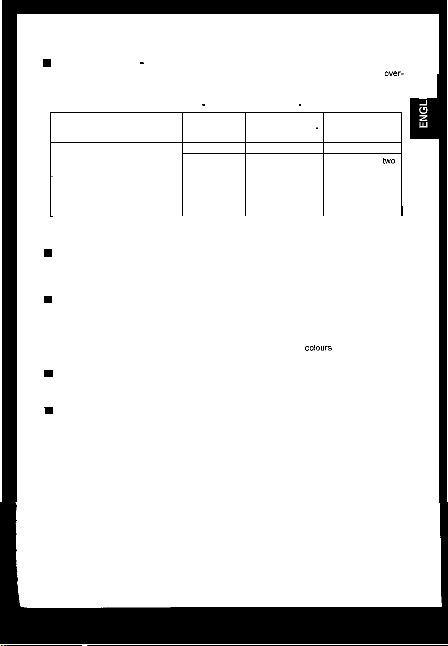
CAUTION for 200 - 240V operation only
This equipment relies on the protective devices in the building installation for short-circuit and over-
current protection. Refer to the following table for the suitable number and location of the protective
devices which should be provided in the building installation.
Protective devices in single - phase equipment or sub - assemblies
Protection Minimum number
against of fuses or circuit
Equipment to be connected to
POWER SYSTEMS with earthed
neutral reliably identified
Equipment to be connected to any
supply, including IT POWER
SYSTEMS and supplies with
reversible plugs
I
Verify that the protective devices in the building installation meets the conditions in the table prior to
installing the equipment.
W
BE CAREFUL OF POWER CORD CONNECTION !
Before inserting the plug of the power cord into a receptacle of the correct voltage, check that the
connection portion of the power cord is clean (with no dust).
a receptacle firmly, otherwise it may cause electrical shock or fire.
H REMOVE THE POWER CORD FOR COMPLETE SEPARATION !
For complete separation from the power source, remove the power cord from the monitor or from the
wall outlet.
n
AVOID FREQUENT POWER ON-OFF SWITCHING !
DO NOT repeat OFF and ON in a short period. It may cause blurred colours or distortion of the
displayed pattern.
W
BE CAREFUL OF STATIC ELECTRICITY ON CRT SURFACE !
To prevent electrical shock by the static electricity on the CRT surface, disconnect the power cord at
least 30 SECONDS AFTER turning off the power.
Earth faults
Over-current
Earth faults
Over-current
breaker poles
1
1
2
1
I
Then, insert the plug of power cord to
-
Location
Both conductors
Either of the two
conductors
Both conductors
Either of the two
conductors
I
q
I
W
ABOUT CLEANING
This monitor has a non-glare and anti-electrostatic treatment on the surface of the screen.
water or alcoholic solvent with soft cloth like gauze to clean the surface of the screen.
NEVER use abrasive, glass cleaner containing highly concentrated ammonia and strong base
chemicals since they damage the surface treatment.
Clean the cabinet and controls with a lightly moistened soft cloth.
DO NOT use aerosol sprays, solvents or abrasive cleaners.
Use
3
I
Page 6
W
FCC (Federal Communications Commission) STATEMENT WARNING
WARNING : This equipment has been tested and found to comply with the limits for a Class B
digital device, pursuant to Part 15 of the FCC Rules. These limits are designed to provide
reasonable protection against harmful interference in a residential installation. This equipment
generates, uses, and can radiate radio frequency energy and, if not installed and used in
accordance with the instructions, may cause harmful interference to radio communications.
However, there is no guarantee that interference will not occur in a particular installation. If this
equipment does cause harmful interference to radio or television reception, which can be
determined by turning the equipment off and on, the user is encouraged to try to correct the
interference by one or more of the following measures:
-
Reorient or relocate the receiving antenna.
-
Increase the separation between the equipment and receiver.
-
Connect the equipment into an outlet on a circuit different from that to which the receiver is
connected.
-
Consult the dealer or an experienced radio I TV technician for help.
Instructions to Users : This equipment complies with the requirements of FCC (Federal
Communication Commission) equipments provided that following conditions are met.
(1) Power cord : Unshielded power cord must be used.
(2) Video inputs : The input signal amplitude must not exceed the specified level.
CAUTION : Changes or modifications not expressly approved by the party responsible for
compliance could void the user’s authority to operate the equipment.
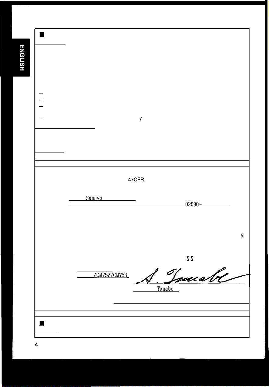
Declaration of Conformity
Class B Personal Computers and Peripherals;
According to
47CFR.
Part 2 and 15 for
and I or
CPU Boards and Power Supplies used with Class B Personal Computers:
We:
Located at:
Declare under sole responsibility that the product identified herein, complies with 47CFR Part 2
and 15 of the FCC rules as a Class B digital device.
representative unit tested and found to be compliant with the standards. Records maintained
continue to reflect the equipment being produced can be expected to be within the variation
accepted, due to quantity production and testing on a statistical basis as required by 47CFR
2.909.
harmful interference, and (2) This device must accept any interference received, including
interference that may cause undesired operation. The above named party is responsible for
ensuring that the equipment complies with the standards of 47CFR§ § 15.101 to 15.109.
Trade name:
Model Number:
Signature of Party Responsible:
Printed name of Party Responsible:
Nissei
Sanevo
America, Ltd.
200 Lowder Brook Drive Suite 2200, Westwood, MA. 02090- 1124 U.S.A.
Each product marketed, is identical to the
Operation is subject to the following two conditions: (1) This device may not cause
Color Monitor
CM751
/CM752/CM753
Satoshi
Tanabe
5
Executed on (Date), at (Place):
W
FOR THE CUSTOMERS IN CANADA
NOTICE : This Class B digital apparatus complies with ICES-003.
June 5. 1998.’ MA.. U.S.A.
Page 7

J
W
FOR THE CUSTOMERS IN THE U.K.
THIS PRODUCT IS SUPPLIED WITH A TWO PIN MAINS PLUG FOR USE IN MAINLAND
EUROPE.
FOR THE U.K. PLEASE REFER TO THE NOTES ON THIS PAGE.
-IMPORTANT
WORDING FOR CLASS I EQUIPMENT INSTRUCTION BOOKS AND LABELS
The mains lead on this equipment is supplied with a moulded plug incorporating a fuse, the
value of which is indicated on the pin face of the plug.
an ASTA or BSI approved BS 1362 fuse must be used of
detachable never use the plug with the cover omitted.
ensure it is of the same colour as that visible on the pin face of the plug.
available from your dealer.
DO NOT cut off the mains plug from this equipment.
power points in your home or the cable is too short to reach a power point, then obtain an
appropriate safety approved extension lead or consult your dealer.
Should it be necessary to change the mains plugs, this must be carried out by a competent
person, preferably a qualified electrician.
If there is no alternative to cutting off the mains plug, ensure that you dispose of it immediately,
having first removed the fuse, to avoid a possible shock hazard by inadvertent connection to the
mains supply.
FOR UNITED KINGDOM
Should the fuse need to be replaced,
the same rating. If the fuse cover is
If a replacement fuse cover is required,
Fuse covers are
If the plug fitted is not suitable for the
WARNING: THIS EQUIPMENT MUST BE EARTHED
IMPORTANT
The wires in the mains lead are coloured in accordance with the following code:
Green and Yellow = Earth, Blue = Neutral, Brown = Live.
Green & Yellow
to Earth
Brown to Live
Fuse
Blue to Neutral
As these colours may not correspond with the coloured markings identifying the terminals in
your plug, proceed as follows:
The wire which is coloured GREEN and YELLOW must be connected to the terminal in the plug
which is marked with the letter E or by the earth symbol @ or coloured GREEN or GREEN and
YELLOW.
The wire coloured BLUE must be connected to the terminal marked with the letter N or coloured
BLUE or BLACK. The wire coloured BROWN must be connected to the terminal marked with
the letter L or coloured BROWN or RED.
Cord Clamp
Page 8

Install the monitor in the following way, taking care to maintain safety.
1.
Installation
Install the monitor on a horizontal base.
Front Cover
CRT Surface
Power Switch
Control Panel
Tilt & Swivel Base
2. Power Cord Connection
@
Make sure of using the power cord meeting the safety standard of the
country in which you are using the monitor.
@
Insert the connector of a power cord to the AC Inlet of the monitor.
@I
Insert the plug of the power cord to a receptacle of the correct voltage.
3. Signal Cable Connection
(iJ
Insert the connector of a signal cable to the Signal Input Connector of
the monitor, with attention to the suitability, and secure the screws on the
connector shell firmly.
@
Connect the another connector of the signal cable to the host computer.
FRONT VIEW
AC Inlet
Connector
,
REAR VIEW
Signal Input
Connector
/
j!
A receptacle of
the correct voltage
\
‘4
6
Power
COI
rd
\
Signal Cable
/
to the host computer
Page 9

l
Use a signal cable with the D-Sub Mini
15pin
Connector.
3
l If the graphics board supplies more than one type of sync. signal, the sync.
signal type will be automatically selected by the monitor, with the priority
shown in the following table.
4. Power On
Turn on the Power Switch of the monitor first, then the computer.
Paae 9 “POWER
NOTICE :
n
After turning OFF the switch, wait at least 5 seconds to restart the monitor.
monitor may operate unusually.
n
If the picture doesn’t appear, turn OFF the power switch, make sure of the following and wait
at least 30 seconds to restart the monitor.
Make sure the power switch of the computer, power cord connection, signal cable
connection and the input sync. signal are right.
W
If the colour is impure on the screen after turning ON the monitor, wait for about 10 minutes
and press the DEGAUSS button.
ON/OFF”
Refer to
Otherwise the
Page 10

Microprocessor-based preset functions can store 26 sets of geometry
settings including the standard settings.
The following industrial standard settings have been preprogrammed by the
factory.
No.
Video Mode Name Horizontal
(with Resolution and Frequency
Vertical Frequency)
1
VGA 640 X 480 -60
2
VESA 800 X
3
VESA1024 X
4
VESA1280
5
VESA1600
6
VESA1600
600
- 85
768- 85
X 1024- 85
X 1200
- 75
X 1200- 85
Hz
Hz
Hz
Hz
Hz
Hz
31.47 kHz
53.67
kHz
68.68 kHz
91.15 kHz
93.75
kHz
106.25 kHz
Video Model
VGA
VESA
VESA
VESA I5
VESA I5
VESA
;;;;;E;
b
L L
L
-
/
CM753ET (
&
b
lb
.b
NOTE :
W
Input signals with approximately the same frequencies may be regarded as the same signal.
n The following horizontal timing conditions are recommended (at sync. H, V separate or
composite).
for 31 kHz - 52 kHz horizontal frequency:
Horizontal front porch should be more than 0.1
Horizontal sync. width should be within 1 .O - 3.8
Horizontal back porch should be more than 1.2 ys.
Horizontal blanking width should be more than 3.5
for 52
kHz
- 107
kHz
Horizontal front porch should be more than 0.1
Horizontal sync. width should be within 0.8 - 3.0
Horizontal back porch should be more than 1 .I us.
Horizontal blanking width should be more than 2.4
n The following vertical timing conditions are recommended.
Vertical front porch should be more than 9 ys.
Vertical sync. width should be less than 100 us.
Vertical back porch should be more than 400
Vertical blanking width should be more than 450 us.
n
In case the front or back porch is extremely long, or the data display time is extremely short,
it may not be able to set the expected size and position.
W
Standard settings are subject to change without notice.
W
This monitor is tested and conformed compliance with ZH1/618 and
3) ergonomics requirement on the following video modes :
“VESA 1024 X 768 - 85 Hz”
“VESA 1280 X 1024 - 85 Hz”
horizontal frequency:
IJS.
us.
ps.
us.
l~s.
us.
us.
EN29241-3
(lSO9241-
HN
8
Page 11

Adjust Switch
I
Page
Page 9 “POWER
I
9 “DEGAUSSING”
ONIOFF”
Page 13
Select Switch
“STORE”
I
Page 9-12 “ADJUSTMENT”
I
POWER ON/OFF
0
Press the Power Switch
n
When power is ON, the power LED lights.
(a),
to switch the power ON/OFF.
DEGAUSSING
0
Press the switch B, to degauss manually.
W
Use this function only when you see colour impurities on the screen after turning ON the
monitor. Remember, the monitor is automatically degaussed during initial power on.
n Wait for about 10 minutes before repeating the function.
ADJUSTMENT
l
Press the select switch of the item you want to adjust.
by the adjust switches shown in following tables.
n You can store the adjusted condition.
n The On Screen Display function of “EasyMenu” shows
selected items and adjusting conditions. You can select the
EasyMenu Language. See the table below.
Refer to Page 13 “STORE”.
Then you can adjust
I.
. . . . . . . . . . . . . . . . . . . . . . . . . . . . . . . . . . . . . . . . . . . . . .
0 CONTRFlST
1
-4-I)+ :
I
.:
i
Item
Select
I I
Select
Switch
simultaneously.simultaneously.
Adjust
Adjust
Switch
I I
\ I
next mode.
\ I
next mode.
changes the
language to the
previous
mode.
Sample of
Function
-
“EasyMenu”
Page 12

Item
Contrast
Brightness
H. Position
H. Size
V. Position
Select
Switch
@y
l&g
&
&
c=+$
--O+
4;rp
&
&
&j$
--O+
F
&=+I$
Adjust
Switch
Function
makes Contrast brighter excluding background.
--O+
-&
makes Contrast darker excluding background.
--Of
TF
&
makes Brightness brighter including back-
ground
&
makes Brightness darker including background.
moves the position to the right.
--O+
OFI
moves the position to the left.
_ ’ +
T?
&
expands horizontally.
&
shrinks horizontally.
moves the position up.
moves the position down.
--O+
expands vertically.
shrinks vertically.
rotates clockwise.
rotates counter clockwise.
curves the left/right sides outwards.
-Of
curves the left/right sides inwards.
--O+
erpands the top side, and shrinks the bottom
stde.
shrinks the top side, and expands the bottom
side.
@pq$
@
&
Y
FF
F
&
&
-9
F
--Ot
-*+
--O+
--O-k
F
&
&
&
&
9
FF
&
&
&
V. Size
Rotation
Pincushion
Trapezoid
W
When EasyMenu is not shown, you can start the adjustment of Contrast and Brightness only,
without pressing any select switch.
n It is recommended to follow the following procedures for the adjustment of distortions
“Right Pincushion” and “Right Trapezoid”
-
(Adjust the right side.)
10
“Rotation”
“Pincushion” and “Trapezoid”
-
(Adjust the lefl side.)
;
Page 13

ADJUSTMENT (Continue)
Item
ight
incushion
Select
Switch
ight
rapezoid
shrinks the right top side, and
the right bottom side.
olour Select
Zolour
3alance
Red
Green
&and m
simultaneously.
Nhen Green or
Blue is selected.
&
is valid
singly.
m
@J
and
I
I
simultaneously.
1
P/hen
Blue or
Red is selected,
&
is valid
singly.
=&q$
IF&l
&&I
m
changes the colour to
makes the Red stronger.
When the Red reaches the upper
limit, it makes the Green and Blue
weaker.
makes the Green and Blue stronger.
When the Green or Blue reaches the
upper limit, it makes the Red weaker.
makes the Green stronger.
When the Green reaches the upper
limit, it makes the Blue and Red
1
weaker.
makes the Blue and Red stronger.
When the Blue or Red reaches the
upper limit, it makes the Green
weaker.
makes the Blue stronger.
When the Blue reaches the
limit, it makes the Red and Greer
weaker.
makes the Red and Green stronger.
When the Red or Greene reaches thr
upper limit, it makes the Blue weaker.
cancels the currently adjusted colour
and calls the colour condition of
previously selected colour mode.
Blue
Colou
Resel
j&and @J
simultaneously.
When Green or
Red is selected,
@J
is valid
singly
(This operation
lr 1
valid only wher
Red, Green
Blue is selectee
already.)
is
OI
simultaneously,
for about
2 seconds.
H The mode “No.4:USER” is not factory set, and it is programmable if desired.
After adjustment of “Colour Balance” (Red, Green or Blue) and “STORE” (refer to page
your colour balance will be restored by selecting “No.4:User”.
expands
No.4 : User
(if available)
uppel
the
13).
1^.
11
Page 14

ADJUSTMENT (Continue)
Item
* b401RE
-I.
Moire
?eduction
i/.
Moire
deduction
lo\ol
simultaneously.
”
UDlRE
@and
simultaneously.
Select
Switch
and
Adjust
Switch
Function
@J
the horizontal moire changing
I
makes the operation of the horizontal
moire changing circuit stronger.
moire changing circuit weaker.
&
o.perftes
m
1 crrcurt.
the vertical moire changing
I
stops the vertical moire changing
A
I circuit.
makes the operation of the vertical
moire changing circuit stronger.
makes the operation of the vertical
moire changing circuit weaker.
n Moire may appear on the screen due to interference between CRT dot pitch and video signal
by conditions of video image, display size, display brightness, etc.
display size, display brightness, etc., before the adjustment of moire.
Adjust the conditions of
n In some cases, this function may cause deterioration of display quality, such as focus, jitter,
etc.
W
The condition of the moire changing circuit will be indicated by pressing the select switch
m,
as the following.
Indicated symbol
I
n
Moire changing circuit condition
Horizontal Vertical
ON
I
ON
I
ON
OFF
!. . . . . . . . . . . . . . . . . . . . . . . . . . _ ,
CB CONTRClST
-4-I)+
?tf
BRIGHTNESS
-4-I)+
I
a: 80kHr/ 75Hz i
: . . . . . . . . . . . . . . . . . . . . . . . . . . . . . . . . . . . . . . . . . . . . . . . . . . .
Sample of “EasyMenu”
‘f
i
:
i
i
Page 15

STORE
0
Press the switch
m,
to store the currently adjusting data,as follows.
kern
H.Position
H.Size
V.Position
V.Size
Pincushion
Trapezoid
Right Pincushion
Right Trapezoid
H.Moire Reduction
V.Moire Reduction
Colour Balance
(Red, Green, Blue)
j
Rotation
Contrast
Brightness
Colour Select
Language Select
One setting is allowed for each video mode.
YOU can store a maximum 26 sets of geometry detects
settings including the standard settings (refer to mode.
page 8 “STANDARD SETTINGS”).
n If your store is at its maximum already,
storing a setting for a new video mode
overwrites the oldest user setting.
n The video mode is distinguished by the
horizontal/vertical frequency and polarity of
the horizontal/vertical sync. signal.
When the video modes are almost similar in
these factors however, the video modes
may not be discriminated as different.
Ine
setting is allowed for to the colour balance When the colour balance
‘No
4USER”.
. .
Ine
setting is allowed.
Ine
setting is allowed.
n It is normally not necessary to store them
manually. No operation of about 8 seconds
stores the currently adjusting data of these
items, automatically.
Storing Condition Restoring Condition
When the monitor
the
same video
“No
4USER”
. .
selected.
When the monitor
detects a valid signal.
is
RESET
0
Only when you want to cancel all your storing data,
turn ON the power switch (Q) while pressing the
switches
storing data will be lost and the all adjustment condition will be returned to the
original settings.
&
together, to reset to the original standard settings. All your
SIGNAL CHECK
0
To refer to the input signal condition, press the
switch of the
The horizontal frequency and vertical frequency will
be indicated.
n
Precision frequency,
Horizontal approximatelyzk 2 kHz
Vertical approximately
@?I
(CONTRAST/BRIGHTNESS).
2 2Hz
CB
CONTRAST
-4-I)+
G
BRIGHTNESS
-4-I)+
i
. . . . . . . . . . . . . . . . . . . . . . . . . . . . . . .
Sample of
“EasyMenu”
80kHr/ 75Hz i
13
j
Page 16

AUTOMATIC SIGNAL CHECK
0
When the monitor has detected
the change
monitor will indicate the condition automatically, as follows.
of the
signal input
condition,
the
Condition
When the monitor detects
proper signal.
When the monitor detects
no sync. signal.
When the monitor will go
into the power saving
mode.
(Refer to page 15)
When the monitor detects
a sync. signal which is out
of set-up specification or
is unstable.
VIDEO
MUTING
I
The EasyMenu indicates the horizontal
frequency and vertical frequency.
H Precision frequency,
Horizontal approximately *2
Vertical approximately
The EasyMenu indicates the message
“INVALID SYNC.” for 5 seconds.
n Verify power switch of the computer
and cable connection.
The LED of the power switch
flashes.
n Verify power switch of the computer
The EasyMenu indicates the message
n Verify the specification of input
Indication
(a)
&2
kHz
Hz
Sample of “EasyMenu”
,.........._.__________...______..
80kHz/ 75112
:................................;
,.._________.........________...._
INWLID SYNC.
i
:................................;
-
j
INVALID SCFlN
FREQ .
l When the monitor has detected the change of the signal input condition, the
monitor mutes the picture automatically.
This function hides scrambled images which may appear during the changing
period of the input signal.
The muting period depends on the time that elapses before the replaced
signal becomes stable.
Page 17

l This monitor complies with VESA and ENERGY STAR@ power saving
requirements. The power saving system works only when used with VESA
DPMS compliant PC’s and/or graphic controllers.
m
VESA DPMS
Mode
ON
Stand-by
Suspend
OFF
0
This monitor complies with VESA
Video
Active Yes
Blanked
Blanked
I
Blanked
H. Sync.
I
No
Yes
No
V. Sync.
I
Yes
Yes
No
No
DDC1/2B
125 W (typical)
I
approx. 4 W
Power Saving States
Power
less than
15w
Power LED
Lighting Green
Flashing quickly
I
Flashing Slowly
specifications. Plug 8 Play is a
system with computer, peripherals (including monitors), and operating system.
It works when the monitor is connected to DDC ready computer that is
running an operating system software that incorporates plug & play
functionality .
.I
15
Page 18

19 inch picture tube, 0.22 mm horizontal dot pitch,
(0.21mm
lnvar shadow mask, Black matrix, Short persistence
phosphors, Dark Tint Anti-Reflection coat.
horizontal mask pitch) ,
Input Signal
Synchronization
Resolution
Video Clock Frequency
Viewable
Image Size
Viewable Image Area
Colour Temperature
Warm-up Time
Power Supply
Dimensions
Video
Sync.
Horizontal : 31 - 93
Vertical :
Horizontal : Up to 1600 dots
Vertical : Up to 1280 lines
18.0 inches (458 mm), diagonal (typical)
Horizontal : 367 mm (typical)
Vertical : 276 mm (typical)
Standard Colour Balance 1 : 9300K
Standard Colour Balance 2 : 6500K
Standard Colour Balance 3 : 5000K
Colour Balance 4
30 minutes to reach optimum performance level.
AC 100 - 120 / 200 - 240 V, Automatically select.
Provided with Power Save Circuit.
Power Consumption
448 (W) x 454 (H) x 460 (D) mm
including Tilt & Swivel base.
: 0.70 Vp-p, Analog
:
Separate H, V or Composite HN
TTL level or Sync. on Green at 0.30 Vp-p
CM751 ET
kHz
50-160Hz
CM751 ET
200 MHz
(typical)
CM752ET
31 - 101 .O kHz 31 - 107
50 - 160 Hz
CM752ET CM753ET
210 MHz 230 MHz
(typical)
: User defined
: 125 W (typical)
CM753ET
50-
(typical)
kHz
160 Hz
Weight
Environmental
Condition
Specification and Design are subject to change without notice.
16
25 kg
Temperature
Humidity
Operation
:
5°C to 40°C -20°C to 60°C
:
10% to 80% 10% to 90%
Storage
 Loading...