

Page 1
HITACHI
COLOUR MONITOR
USER MANUAL ....1
CM620ET
CM630ET
with EasyMenu !
EasyMenu is HITACHI’S On Screen Display function for easy operation.
BEDIENUNGSANLEITUNG ..13
MANUAL DE USUARIO ..25
READ THE INSTRUCTIONS
INSIDE CAREFULLY.
KEEP THIS USER MANUAL
FOR FUTURE REFERENCE.
For future reference, record the serial number
of your colour monitor.
SERIAL No.
The serial number is located on the rear of the
monitor.
f
,,
‘1
/
1
}:
/ r.
,.
Q%
EPA POLLUTIONPREVENTER
This monitor is Energy Star compliant
when used with a computer equipped
with VESA DPMS.
The Energy Star emblem does not
represent EPA endorsement of any
product or service.
.-
Page 2
IMPORTANT NOTICE :
Save all packing material warranty void if transported not in original packing!
WICHTIGER HINWEIS :
Bewahren sie die originalverpackung sorgftiltig auf.
Garantieverlust bei
transport ohne originalverpackung!
AVISO IMPORTANTE :
Guardar todos Ios embalajes originales y garantias del material para ser
transportados.
NOTICE :
The information in this document is subject to change without notice. HITACHI
assumes no responsibility for any errors that may appear in this manual.
HINWEIS :
Anderungen der Daten in dieser Bedienungsanleitung sind vorbehalten.
HITACHI i.ibernimmt keine Haftung fur Fehler, die ggf. in dieser Anleitung
enthaiten sind.
NOTA :
La informacidn contenida en este manual est~ sujeta a cambios sin previo
aviso, HITACHI no se responsabiliza de Ios errores que pueda contener este
manual.
Page 3
1. lNTRODUCTION .....................................................................................
2. cAuTioNs .. ........ .......... ........ ............................. ................ ...... ...............2 —
Im
—
3. CHECKLIST.................. ..................................... ..................... ................5 ~
4. lNSTALWTION............................................... ....... ........ ....... ................. .
5. USE OF TILT.SWIVEL ............................................................................6
6. CONTROLS AND ADJUSTMENTS ........................................................7
7. POWER MANAGEMENT SYSTEM ......................................................lO
8. PLUG& PWY ........................................................................................lO
9. LOW RADIATION CHAWCTERISTICS ................................. ..............lO
10. SPECIFICATION ...................................................................................ll
11. FACTORY PRESET DISPLAY MODES ................................................l2
12. TROUBLE SHOOTING .........................................................................l2
colour monitor is an excellent choice when you need very high resolution
This
compatibility and versatility and quality.
wide range of scanning frequencies and is equipped with an EasyMenu (on screen
display)microprocessor function for adjusting colour balance and picture geometry.
This monitor offers compatibility with virtually every major high resolution video board
for PC and
with APPLE MAC II by using an inexpensive optional connector.
The unit is also equipped with an energy-saving function. It meets the EPA Energy
Star, VESA DPMS (Display Power Management signaling) standard and NUTEK. The
lowest power consumption is less than 8W.
● VGA, SVGA, XGA, APPLE MAC II, EPA, VESA, NUTEK and TCO are trademarks
/registered trademarks of their respective owners.
video standards including VGA, SVGA, XGA, VESA and is even compatible
It automatically scans to conform with a
5m
Page 4
■ NEVER REMOVE THE REAR COVER!
❑ The rear cover MUST be removed only by authorized service personnel. This color monitor
_ contains high voltage components.
= W
.—
—
THE RECEPTACLE SHOULD BE CLOSE TO THE MONITOR AND EASILY
ACCESSIBLE !
■ INSTALL THE UNIT IN ADEQUATE ENVIRONMENT!
DO NOT exposethis monitorto
is designed to be used in an office or business environment.
DO NOT subject the unit to vibrations, dust, or corrosive gases,
rain or moisture to prevent electric shock or fire hazard. This unit
■ KEEP IN A WELL VENTILATED PLACE !
DO NOT cover this monitor or place anything against any sides (not only top, right and left side but
also rear and bottom side) of unit. Ventilation holes are provided at all sides of the rear cover to
prevent the temperature from rising.
■ KEEP AWAY FROM HEAT SOURCES!
AVOID placing the unit in direct sunshine or near a heating appliance.
■ BE CAREFUL OF MAGNETIC FIELDS !
DO NOT
generate magnetism near the unit. A magnetic field may cause blurred colors or distortion of the
displayed pattern.
place a magnet, loudspeaker system, floppy disk drive, printer, or anything which will
■ BE CAREFUL OF GENERATED MAGNETISM !
After the power has been turned on or “DEGAUSS” button
demagnetized for approximately 10 seconds, This generates a strong magnetic field around the
front rover which may affect the data stored on magnetic tape or disks near the front cover. Place
such magnetic recording equipment and tapes/disks
away from this unit.
has been pressed, the CRT is
■ AMBlENT ILLUMINATION
Avoiddirectrays ofthe
sun or room lighting onto the CRT screen in order to prevent eye fatigue.
■ THE ENCLOSED POWER CORD SHALL BE USED IF PROVIDED!
In Europe,a properEuropeanstandardapprovedpowercord
rated current up to 6A, a type not lighter than H05W-F 3G 0.75 mmz or H05WH2-F 3G 0.75 mmz
shall be used.
In USAJCanada, use a UL LISTED/CSA LABELLED or CERTIFIED power cord set meeting the
following specifications
Rating: min. 125V, 7A
Length: max. 3.1 m
Type: S/l or SJT
Plug type NEMA 5-15P, Parallel blade, Grounding type, 125V, 15AFailure to do so may cause
fire or electric shock hazard.
is to be used with this monitor. For a
■ USE ONLY THE CORRECT VOLTAGE POWER OUTLET WITH SAFETY
GROUND CONNECTION !
V (for CM620ET) or 100-120 V (for CM630ET) for USA, Canada, etc.
120
200-240 V for Europe, etc.
(This monitor automatically adjust to the input voltage 100- 120/ 200- 240V.)
2
Page 5
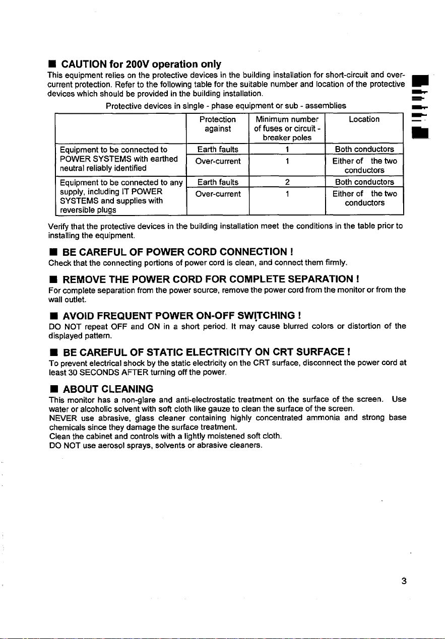
■ CAUTION for 200V operation only
This equipment
current protection. Refer to the following table for the suitable number and location of the protective
devices which should be provided in the building installation.
Equipment to be connected to
POWER SYSTEMS with earthed
neutral reliably identified
Equipment to be connected to any
supply, including IT POWER
SYSTEMS and supplies with
reversible plugs
Verify that the protective devices in the building installation meet the conditions in the table prior to
installing the equipment.
relies on the protective devices in the building installation for short-circuit and over-
Protective devices in single - phase equipment or sub - assemblies
Protection Minimum number Location
against
Earth faults
Over-current
Earth faults
Over-current
of fuses or circuit -
breaker poles
1 Both conductors
1
2 Both conductors
1
Either of the two
conductors
Either of the two
conductors
■ BE CAREFUL OF POWER CORD CONNECTION !
Check that the connecting portions of power cord is clean, and connect them firmly.
REMOVE THE POWER CORD FOR COMPLETE SEPARATION !
W
For complete separation from the power source, remove the power cord from the monitor or from the
wall outlet.
■ AVOID FREQUENT POWER ON-OFF SW!TCHING !
DO NOT repeat OFF and ON in a short period. It may cause blurred colors or distortion of the
displayed pattern.
■ BE CAREFUL OF STATIC ELECTRICITY ON CRT SURFACE !
To prevent electrical shock by the static electricity on the CRT surface, disconnect the power cord at
least 30 SECONDS AFTER turning off the power.
w
m
w
i
■ ABOUT CLEANING
This monitor has a non-glare and anti-electrostatic treatment on the surface of the screen. Use
water or alcoholic solvent with soft cloth like gauze to clean the surface of the screen.
NEVER use abrasive, glass cleaner containing highly concentrated ammonia and strong base
chemicals since they damage the surface treatment.
Clean the cabinet and controls with a lightly moistened soft cloth.
DO NOT use aerosol sprays, solvents or abrasive cleaners.
3
Page 6

■ FOR THE CUSTOMERS IN THE U.K.
THIS PRODUCT IS SUPPLIED WITH A TWO PIN MAINS PLUG FOR USE IN MAINIAND
—
EUROPE. FOR THE U.K. PLEASE REFER TO THE NOTES ON THIS PAGE.
iMPORTANT FORUNITEDKINGDOM
WORDING FOR CLASS I EQUIPMENT INSTRUCTION BOOKS AND LABELS
The mains lead on this equipment is supplied with a moulded plug incorporating a fuse, the
value of which is indicated on the pin face of the plug. Should the fuse need to be replaced,
an ASTA or BSI approved BS 1362 fuse must be used of the same rating. If the fuse cover is
detachable never use the plug with the cover omitted.
ensure it is of the same colour as that visible on the pin face of the plug. Fuse covers are
available from your dealer.
DO NOT cut off the mains plug from this equipment.
power points in your home or the cable is too short to reach a power point, then obtain an
appropriate safety approved extension lead or consult your dealer.
Should it be necessary to change the mains plugs, this must be carried out by a competent
person, preferably a qualified electrician.
If there is no alternative to cutting off the mains plug, ensure that you dispose of it immediately,
having first removed the fuse, to avoid a possible shock hazard by inadvertent connection to the
mains supply.
WARNING: THIS EQUIPMENT MUST BE EARTHED
iMPORTANT
The wires in the mains lead are coloured in accordance with the following code:
Green and Yellow = Earth, Blue= Neutral, Brown = Live,
If a replacement fuse cover is required,
If the plug fitted is not suitable for the
Green & Yellow
to Earth
Blue to Neutral
As these colours may not correspond with the coloured markings identi~lng the terminals in
your plug, proceed as follows:
The wire which is coloured GREEN and YELLOW must be connected to the terminal in the plug
which is marked with the letter E or by the earth symbol @ or coloured GREEN or GREEN and
YELLOW.
The wire coloured BLUE must be connected to the terminal marked with the letter N or coloured
BLUE or BLACK. The wire coloured BROWN must be connected to the terminal marked with
the letter L or coloured BROWN or RED.
4
Brown to Live
Fuse
Cord Clamp
Page 7

Before installation, please check the contents of the shlpplng carton. The carton
should contain the following Itf’nls
Colour monitor
Power cord
User manual
Adapter for Apple Mac 11 (option)
[f any of the
above item are missing, contact your supplier as soon as possible.
4. INSTALLATION
Before connecting, make sure that the line voltage is exactly within voltage range
shown on the label located on the rear cover.
voltage where this monitor will be used, consult your local power company or appliance
dealer.
a. Make sure the monitor and the computer are turned off before operation.
b. Plug the power cord into the AC socket on the rear side of the monitor.
c, Plug the other end of the power cord into a power outlet.
d. Plug the free end of the signal cable into the drive connector of the video adapter port
of the computer. Securely tighten the two cable screws on the cable.
When power and signal cable installations are completed, this monitor is ready for
operation,
AC socket
k-l
Pm
If you are uncertain of the type of line
Video cable with 15
pin mail D-SUB
I
connector
/
CAUTION :
When the monitor is turned on continuously for a long period, the phosphors of
the CRT face plate may “burn” leaving a permanent image on the screen. In order
to preserve CRT life, be sure to turn off the monitor or decrease the displayed
intensity when not in use .
5
Page 8

5. USE OF TILT-SWIVEL
k
-
-
—
—
—
–—
With the tilt-swivel base, this unit can be adjusted to be viewed at the angle desired
within
5° 12°
I *
\
Tilt & Swivel
To turn the unit horizontally, grasp it at the bottom with both hands as”illustrated
below.
Range
6
Page 9

6. CONTROLS AND ADJUSTMENTS
I
1. POWER AND POWER SAVING INDICATOR
When the power to the monitor is ON, the indicator is lit. In normal operation, the
indicator is green. While in power saving mode, the indicator will turn to orange.
2. POWER SWITCH
Used to
3. STATUS BUTTON
Used to access Easy Menu(on screen display) as in Fig.A/B overleaf .This gives
access to the following features: Current resolution mode,horizontal and vertical
sync.
position, vertical size and position, pincushion, trapezoid, parallelogram(CM630ET
only), pin balance(CM630ET only), rotation, recall, colour temperature, RGB colour,
power management, manual degauss, Easy Menu stall ), and a description of the
feature currently selected.
To clear the EasyMenu, either push the status bution again or wait for 10 seconds.
The EasyMenu will disappear automatically at that time.
4. FUNCTION BUTTON
Selects which function in the EasyMenu to be adjusted.
5. ADJUST BUTTONS
Used to decrease or increase the parameter bar of the selected function in the
EasyMenu.
turn the power of monitor ON and OFF.
signals, function symbols(including contrast, brightness, horizontal size and
6. SAVE BUTTON
Used to save all function parameter settings which have been adjusted. The
EasyMenu will display “SAVE after the “SAVE” function is completed.
* A total of 41 (for CM620ET) / 42 (for CM630ET) different modes can be stored in
memory and automatically recalled. 6 (for CM620ET) / 7 (for CM630ET) of them are
factory preset for popular graphic standards (see Factory Preset Display Mode on page
12). The remaining 35 modes are reserved for user setting .
Page 10

Front View
L
EasyMenu (on screen display)
Figure A (in case of CM620ET)
.l I I
A
/1
f
— Mode Resolution in Use
~ Frequency of
_ Frequency of
-?
I
\
verlical Sync Signal
horizontal Sync Signal
VGA 640 X 480 ~
31.5 KHz
%iiii
100 ~
CONTRAST
Figure B (in case of CM630ET )
8
— Mode Resolution in Use
~ Frequency of
vertical Sync Signal
— Frequency of
horizontal Sync Signal
Page 11

For each function control, use the adjust buttons “+” and “-” to adjust the monitor’s parameter
bars to your satisfaction according to the following table:
Function
Contrast
0
#J Brightness
El
m
m
l-=-l
~
Horizontal Size
Horizontal Position
Vertical Size
Vertical Position
Pincushion
n
Trapezoid
n
n
D
to)
•1
t-
I-F
L-l
Q
ESC “it
c1
Parallelogram
Pin Balance
Rotation
Recall
R
Co[our
T
1
Temperature
Colour
GB
PM ~a~:ement
Degauss
Save
s
+- –
Contrast Contrast
increased
Brightness
increased
El n
B
m
I--@-l
~
e
++
u
e
+
n
++
D
Qj
Recalls the factory prese
(See Page 12 “FACTORYPRES
To select 9300”K / 6500”K I U!
I
Intensity
increased
OFF
Manual Degaussing
Exit EasyMenu
Manual
decreased
Brightness
decreased
m
‘L
+
L
+
n
i
DISPLAY MOD
intensity
decreased
ON
Auto
CM620ET CM630ET
4
+
—
d
d
J d
d d
d d
d
d
4
J
4
d
:
4
J
d
d
9
Page 12

7. POWER MANAGEMENT SYSTEM
1
—
e specifications. The monitor has a built-in power management system that automatically
s reduces power consumption when the PC is not in use. This power management system
z is effective only when used with VESA DPMS compliant PC or Video Card.
— Table of Power Consumption in each Advanced Power Management (APM) state :
This monitor meets the EPA Energy Star (30 Watts max. in power saving mode),
VESA DPMS (Display Power Management Signaling) standard and NUTEK TCO 1992
APM State
Standby
Suspend
off
N~The power management system is initiated by the video signal sent from the
PC when the monitor is powered on.
system that does not send out video signal (a PC dead on arrival or a PC not
powered on, for example) ,the user can still see the raster on the monitor screen
like a traditional non-power-saving monitor and the power indicator LED will remain
green.
Once the monitor receives the first signal from the PC and initiate the power
management system, the power indicator light will turn green orange according to
the VESA DPMS standard.
This monitor complies with VESA DDC 112B specifications. Plug & Play is a system
with computer, peripherals (including monitors), and operating system. It works when
the monitor is connected to DDC ready computer that is running an operating system
software that is capable for the plug & play.
Signal
Requirement
H.sync. OFF Switches to 15W max. Orange
V.sync. OFF
H.sync. OFF
and
V.sync. OFF
Monitor Action
saving mode &
screen darkens 8W max. Orange
If, however, the monitor is connected to a PC
Power
Consumption
15W max. Orange
Power
Indicator
9. LOW-RADIATION CHARACTERISTICS
Complies with MPR- II and TCO specifications.
Electrostatic potential
Alternating 5Hz-2kHz
electric field 2 kHz -400 kHz
Magnetic field 5Hz-2kHz
2 kHz -400 kHz
I Measurina distance
<500
<25 VJm
<2.5 V/m
<250 nT
<25 nT
I 50 cm around monitor
I
v
~ =30 cm in front of screen)
I Gu
v
<500
<l OVlm*
<l, OVlm*
<200 nT *
<25 nT
I
Page 13

The following are general characteristics :
CRT
Resolution
Input
Video Response
Power
Low Radiation
Plus & Plav
Operating
Weight
Dimensions
Video
Sync.
17 inches,
viewable image size :15.9 inches (404 mm), diagonal
viewable image area : horizontal 325 mm
horizontal dot pitch :
90° deflection, FS double focus, AR-ASC coating
1280 X 1024 max. (de~ends on video card)
0.7 Vp-p, analog
Separate
Composite
Sync. on Green: 0.3VP-P (for CM630ET only)
Horizontal
Vetiical
110 MHz nominal for CM620ET
135 MHz nominal for CM630ET
120 /200 -240 VAC for CM620ET
100-120 / 200-240 VAC for CM630ET
60/50 Hz, 2.5 A max.
Degaussing
Consumption
MPR- II / TCO
VESA DDC ‘“)
Temperature
Humidity
Altitude
17.5 kg (38 lb) approx.
402 (H} X 412 (V!/) X 426 (D) mm
vertical 245 mm
0.24 mm for CM620ET
0.22 mm for CM630ET
: lTL level (+) or (-)
: lTL level (+) or (-)
: 31-69 kHz for CM620ET
31-86 kHz for CM630ET
: 47-130Hz
: line operated automatic& manual
: 115 W max. for CM620ET
135 W max. for CM630ET
(Provided Power Save Circuit.)
: I12B
:5 to 35 degree C
10to 90 %R. H.
:
:Otolooooft
VIDEO CABLE :15 pin, D-type male connector DB-I 5 pin out
1 2 3 4 5 6
R G B Gnd DDC R
Gnd Gnd Gnd
(’) DDC
This specification subject to change without notice .
: Display Data Channel
SDA : Bi-directional Data
SCL : Data Clock
7 8 9
G B
Gnd
10 11
NC Gnd Gnd S:A H
12 13 14 15
v S$L
11
Page 14

11. FACTORY PRESET DISPLAY MODES
The following are factory preset modes :
4
~
Mode name
9
—
Standard VGA 640 X 480
VESA timing
VESA timing
VESA timing
VESA timing
VESA timing
VESA timing
VESA timing
VESA timing
VESA timing
Resolution
640 X 400
1024 X 768
1024 X 768
1280 X 1024
1024 X 768
640 X 480
800 X 600
1280 X 1024
1280 X 960
31.47 kHz 159.9
37.86 kHz 185.1
56.48 kHz 170.1 HZ
60.02 kHz 175.0 Hz
63.98 kHz 160.0 I-fz
68.68 kHz 185.0 HZ
43.27 kHz 185.0
53.67 kHz 185.1
85.94 kHz 185.0
12. TROUBLE SHOOTING
Frequency (H t V)
79.98 kHz 175.0
CM620ET CM630ET
Hz
Hz
Hz –
HZ –
iiz –
HZ –
4
d
d
d
d
d
./
—
—
d
—
d
d
d
d
d
If there is no picture on the screen, check the following:
1. Is the monitor power on ?
If YES, go to the next question.
If NO, turn the power on.
2. Is your computer switch on ?
If YES, go to the next question.
If NO, turn on the computer on.
3. ISthe monitor signal cable connected to the computer’s video card
“D-SUB” connector ?
If YES, go to the nexl question.
If NO, connect the signal cable.
4. Is the power cable fully connected ?
If YES, contact the dealer unit was purchased from.
If NO, attach cable securely.
 Loading...