

Page 1
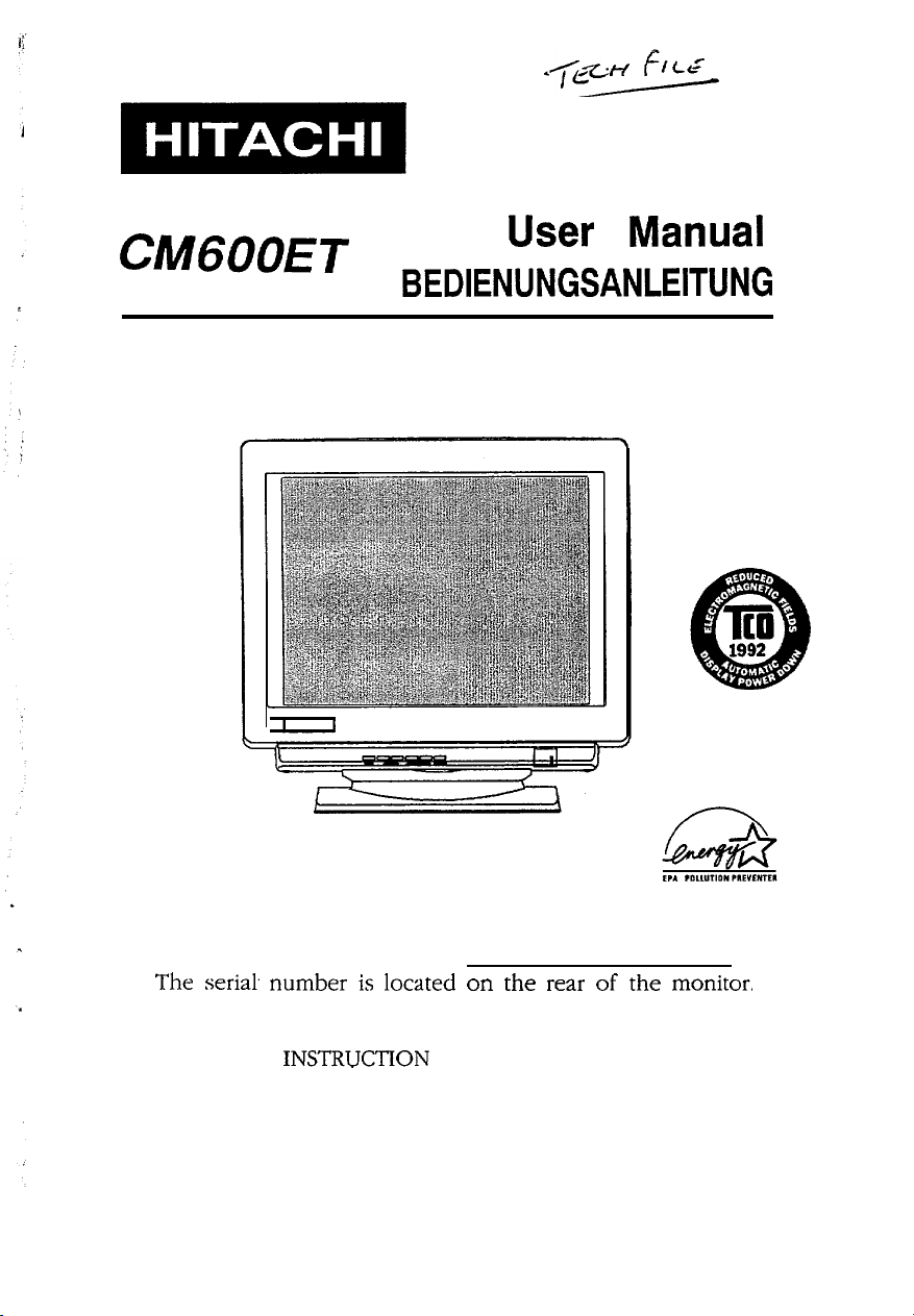
Colour Monitor
CMGOOET
User Manual
BEDIENUNGSANLEITUNG
For future references, record the serial number of your
display monitor, SERIAL No.
The
seria!
number is located on the rear of the monitor,
READ THE INSTRUCTlON INSIDE CAREFULLY.
KEEP THIS USER MANUAL FOR FUTURE REFERENCES.
This monitor is Energy Star compliant when used with
a computer equipped with VESA DPMS.
.
Page 2
INDEX
1.
INTRODUCTION . . . ..I..
2.
CHECK LIST . . . . . . . . . . . . . . . . . . . . . . . . . . . . . . . . . . . . . . . . . . . . . . . . . . . . . . . . . . . . . . . . . . . .
3.
CONTROLS AND ADJUSTMENTS.. ..............................
3.1
LOCATION AND FUNCTION OF CONTROLS.. .......
3.2
REWRITE COMPANY’S NAME ON SCREEN 1 ......
3.3
FUNCTIONS ADJUSTMENTS ON SCREEN 2 ........
. . . . . . . . . . . . . . . . .
.._..........
,
.,.................
2
3
4
4
7
7
POWER MANAGEMENT SYSTEM ................................
4.
PLUG & PLAY.................................................................
5.
INSTALLATION ..............................................................
6.
USE OF TILT-SWIVEL.. ..................................................
7.
SPECIFICATION.. ............................................................
8.
FACTORY PRESET DISPLAY MODES..
9.
TROUBLE SHOOTING.. ..................................................
10
........................
10
11
12
13
14
15
15
-l-
Page 3

1. INTRODUCTION
This colour monitor is an excellent choice for high resolution
compatibility, versatility and quality.
horizontal frequencies between 30 and 64
frequencies between 47 and 104 Hz and is equipped with an Easy
Menu microprocessor controlled multi-frequency function.
This monitor offers compatibility with virtually every major
high resolution video board for PC and video standards including
VGA, SVGA. XGA, VESA and is even compatible with APPLE
MAC II by using an inexpensive optional connector.
The 1280 X 1024 maximum resolution will help you get the
most flesibility with today’s or tomorrow’s PC video standards.
Whether your video adapter has a multi-frequency or fixedfrequency analog colour signal, it will interface with this colour
monitor.
The unit is also equipped with an energy-saving function. It
is compatible with the EPA Energy Star & VESA DPMS
saving standards.
It automatically scans
kHz
and vertical
power-
l VGA, SVGA, XGA, APPLE MAC
trademarks of their respective owners.
-2-
II>
EPA, and VESA arc
Page 4

2. CHECK LIST
Before installation, please check the contents of the shipping
carton. The carton should contain the following items:
-
Power cord
-
User manual
-
Colour monitor
If any of the above items are missing, contact your supplier as
soon as possible.
-3-
Page 5
3. CONTROLS AND ADJUSTMENTS
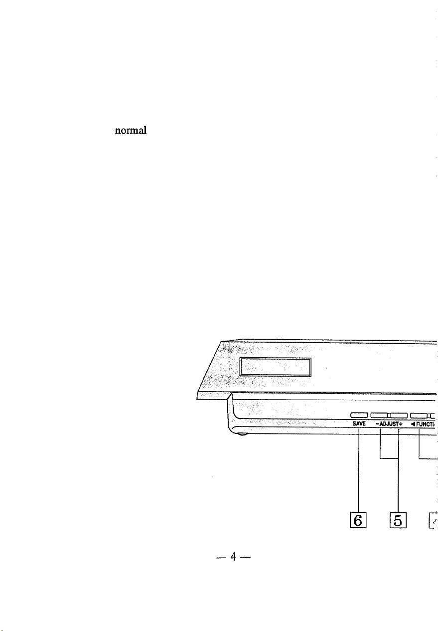
3.1 LOCATION AND FUNCTION OF CONTROLS
1. POWER AND POWER SAVING INDICATOR
When the power to the monitor is ON, the indicator is lit. In
normaI operation, the indicator is green. While in power
saving mode, the indicator will turn to orange.
2. POWER SWITCH
Used to turn the power of the monitor ON and OFF.
3. STATUS SELECT SWITCH (Easy Menu)
Selects from screen 1 or screen 2 images and blanked
windows for display.
Press button. The screen 1 image, as in figure A, will be
shown on the screen. The company’s name, the polarity and
frequencies of the horizontal and vertical sync signals, and
the resolution of the mode which is currently in use now
will be displayed.
Front View
-4-
Page 6

Company’s
Frequency dc Polarity of
Horizontal Sync Signal
Frequency & Polarity of
Vertical Sync Signal
Mode Resolution in Use
Name
Figure A
Press button again and the screen 2 image as in figure B will
appear on the screen.
The fknction symbols (including
Horizontal size and phase, Vertical size and center,
-5-
E
Page 7

Pincushion, Trapezoid, Contrast, Brightness, R. G. B. color,
Image Rotation, Manual Degauss, Window, & Recall), the
function description (simply select to adjust), both step
number and parameter bars (which indicate the adjusting
scale), and the R. G. B. intensity parameter bar, will be
displayed on the screen.
Step No;-255 m m am m
Contmst -
n
1
n
Function Description
fl m
l
&-Parameter
Figure B
To clear the screen, either push the status button again or
wait for about 15 seconds. The window will disappear
automatically at that time.
4. FUNCTION SWITCH
Selects which function on screen 2 to be adjusted.
5. ADJUSTSWITCH
Used to rewrite the company’s name on screen 1 image and
decrease or increase the parameter bar of the selected
function on screen 2 image.
6. SAVE SWITCH
Used to save all function parameter settings which have
been adjusted. The screen will display “Saved” after the
“SAVE” function is completed.
Bar
-6-
Page 8

*Total 32 different modes can be stored in memory and
automatically recalled.
6 of them are factory preset for
popular graphic standards (see Factory Preset Display Mode
on page 15). The remaining 26 modes are reserved for user
setting.
3.2 REWRITE COMPANY’S NAME ON SCREEN 1
The company’s name of this monitor can be rewritten by the
retailer or end-user. The new company’s name may contain up to
IO
characters. Press function keys “a” or
on page 6 to select the character you wish to rewrite and then
continuously press the adjust switch
a letter or number. The alphabet and numerals will be displayed
in sequence.
Press “SAVE” key to save new company’s name.
“-”
“D”
as shown in item 4
or
“+‘I
in order to select
3.3 FUNCTIONS ADJUSTMENTS ON SCREEN 2
For each function control, use the adjustment switch’s “t”
and
“-”
buttons to adjust the monitor’s parameter bars to your
satisfaction according
to the following table:
-7-
Page 9

El
cl
El
cl
F!l
c)
G
B
@
-CL
-
-
-
cl
m
.~
VERTICAL.
CENTER’
CONTRAST
BRIGHTNESS
COLOR
3
IMAGE
ROTATION
CRT
DEGAUSSING
WINDOW
RECALL
El
,.:
/--J
cl
El
El
cl
0
CONTRAST
INCREASku
INTENSITY
INCREASED
Cl)
MANUAL DEGAUSSING
m
cl
RECALLS THE FACTORY PRESET
MODES-SEE
PAGE
CONTRAST
INTENSITY
REDUCED
15
0)
cl
B
-8-
Page 10

Rear View
1.
AC socket
Connect one end of the supplied power cord to this socket and
the other end to the AC power outlet of the computer.
2. Connect video cable with 15 pin male D-SUB connector to
the PC Video card.
-9-
Page 11

4. POWER MANAGEMENT SYSTEM
This monitor meets the EPA Energy Star (30 Watts max. at
power saving
Management Signaling) standard. The- monitor has a built-in
power management system that automatically reduce power
consumption when the PC is not in use.
management system is effective only wheri used with VESA
DPMS compliant PC or Video Card.
Table of Power Consumption in each Advanced Power
Management
Note: The pdwer management system is initiated by the video
signal sent from PC side when the monitor is powered on.
If, however, the monitor is connected to a PC system that
does not send out video signal (a PC dead on arrival or a
PC not powered on, for example), user can still see the
raster on the monitor screen like a traditional non-power-
saving monitor. And the power indicator LED will stay
green.
mode) & VESA DPMS (Display Power
And the power
(APM)
state:
Once the monitor receives the first signal from PC side
and initiate the power management system, the power
indicator light will turn green or orange according to the
VESA DPMS standard.
- lo-
Page 12

5. PLUG & PLAY
The monitor complies with VESA DDC (Display Data
-
Channel)
95. The main function is to allow communication between
monitor and video card (or PC).
compliant video card (or PC). By means of a software driver for a
DDC video card (or Windows 95 operation system), all
informations
resolution, refresh rate and other data related to the monitor can be
displayed for user’s reference.
for example select (DDC2 only) display mode with a different
combination of resolution and refresh rate that supports the intended
application.
DDCl/DDC2B to support “plug & play” for Windows
The function is effective only when used with a DDC
stored within the DDC device in the monitor such as
Based on this information, users can
-
11
-
Page 13

6. INSTALLATION
Before connecting, make sure that the mains voltage is exactly
within voltage range shown on the label located on the rear cover,
If you are uncertain of the type of line voltage where this monitor
will be used, consult your local power company or the dealer.
a. Make sure the monitor and the computer are turned off before
*
installation.
b. Plug the power cord into the connector on the rear side of the
monitor.
c.
Plug the other end of the power cord into the wall power outlet.
d. Plug the free end of the signal cable into the drive connector of
the video adapter port of the computer.
cable screws on the cable.
When power and signal cable installations completed, this
monitor is ready for operation.
Securely tighten the two
: %I,,,
I,
;
When the monitor is turned on continuously for a long
period, the phosphors of the CRT face plate may “burn” leaving
a permanent image on the screen. In order to preserve CRT
life, be sure to turn off the monitor or decrease the displayed
intensity when not in use.
2. .’Long time operation, using out of range signal may cause
damage of the monitor. Please observe specification of the
monitor.
- 12-
Page 14

15
,d
*
7. USE OF TILT-SWIVEL
With the tilt-swivel base, this unit can be adjusted to be
viewed at the angle desired within 100” horizontally and 16.5”
vertically.
To turn the unit horizontally, grasp it at its bottom with both
hands as illustrated below.
Page 15

8. SPECIFICATION
‘he following are
CRT
VIEWABLE
IMAGE SIZE
VIEWABLE
IMAGEAREA
RESOLUTION
INPUT
VIDEO
SYNC
POWER
PLUG&FLAY
OPERATING
WEIGHT
DIMENSIONS
neral characteristics:
g,
17” , 0.28mm dot pitch, 90”
tint,FS double focus, Non-glare ASC coating.
159”(404mm),
325mm(H) X 245mrn(V)
1280 X 1024max.(depend the video card)
Analog
Separate
Composite :TTL
Horizontal : 30-64KHz
Vertical :47-104Hz
108264VAC,
Degaussing
Consumption:llSW
VESA Display Data Channel(DDC):
Temperature :0 to 40 degree C
Humidity
Altitude
17.5Kg(38.5lb.)Approx
402(H) X 412(W) X 426(D)mm
(15.83 X 16.22 X 16.77)inch
diagonal
:0.7 Vp-p, 75 ohm, RGB(+)
:TTL
level(+
level(+
50-60Hz. 2.5A(max.)
:line
operated automatic
manual
max
: 10 to 90% R.H.
:o to 10,000ft
deflection, dark
&
1/2B
VIDEO CABLE 15 pin, D-type male connector
DB-15 pin out
5
6
7
8
9
10
1234
RGBGnd
*VESA Display Data Channel (DDC) standard
SDA:Bi-directional Data
SCL:Data Clock
This specification subject to change without notice.
DDC R G B NC Gnd Gnd *SDA H V *SCL
Gnd Gnd Gnd Gnd
- 14-
11
12 13
14
15
Page 16

9. FACTORY PRESET DISPLAY MODES
The following are factory preset modes:
.._. -1 m6~~:~g+&t7;E+-:~. ,“:::; d “.‘R;$~~$‘i;“t’fgh3
:.- ,: i ;
F;ei’.e;;:cy$pyl$)T;
Standard VGA
VESA Standard 640 x 480 37.86KHzl%!:‘8Hii
VESA Standard 800 i 600
VESA Standard
VESA Standard
VESA Standard
640 Ix 480
1024 x 768
1024x768
1280 x 1024
3 1.47KHilrj;s;;s@;
48.08KHzT72:‘OHi?
60.02KHz/7.5’;OH$
56,48KH2726.‘1H~:..
63.98KB~~6o”.‘tiH~;:’
lO.TROUBLE SHOOTING
If there is no picture on the screen, check the following:
Is the monitor power on?
1.
IfYES,go to’the next question
IfNO,turn
Is your computer switch on?
2.
IfYES;go-tothe
IfNO,turn
Is the monitor signal cable connected to the computer’s video
3.
card “D-SUB” connector?
IrrES;g~~~~h~.~ext”sue~ti~~‘~~~‘~~?!;
IfNO,connect
the power on.
;‘.
next question,
the computer on.
::T~.‘:.” 1, l ,, ,.__,_ __if =,~~‘i”,~;,*
the signal cable.
., :~~~i.~~::~~;‘:‘-
.- .; _~. :‘71;F’i!:;;**
,“;“;“;,$:,y,l’
...,:“‘r::~.
...y~‘;~,.
‘.’ :y.:::i i~~;;.i?n~~~ijei;~~~;:
*I
‘>:ce:m ;
““., ,,;yy: Cf_,’ ~~
.;-:,7:,
,= . .
‘.,l
!‘:!,,,‘,’
4.
-
15
-
 Loading...