

Page 1
HITACHI
COLOR
DISPLAY
CM2186A
OPERATING
GUIDE
For ‘future
Model No.
The numbers are located on the rear of the set.
Read the instruction inside carefully.
Keep this manual for future reference.
reference,record
the model and serial number of your display monitor.
Serial No.
Page 2
All Rights Reserved
Printed in Japan
NOTICE
The information in this document is subject to change without notice. Hitachi
assumes no responsibility for any errors that may appear in this document.
FCC STATEMENT For USA Model
The
following statement applies to this HITACHI product. Federal Communication
Commission (FCC) Statement
Barning:
(CM2186A3LN)
WARN I NG- This equipment generates, uses, and can radiate radio frequency
energy and if not installed and used in accordance with the instructions manual,
may cause interference to radio communications. It has been tested and found to
comply with the limits for a Class A computing device pursuant to Subpart J of
Part 15 of FCC Rules, which are designed to provide reasonable protection against
such interference when operated in a commercial environment. Operation of this
equipment in a residential area is likely to cause interference in which case the
user at his own expense will be required to take whatever measures nay be
required to correct the interference.
-2-
Page 3
INSTRUCTIONS TO USER:
This equipment complies with the requirements of FCC (Federal Communication
Commission) Class A equipments provided that the following conditions are met.
(1) Video signal cables:
Double shielded
the outer shield should be connected to the ground.
are used, the cables should be enclosed in metal pipes or similar way to reduce
the interference noise radiation.
(2) Power cord:
Shielded power cord should be used.
ground.
(3)
Video inputs:
The input signal amplitude must not exceed the specified level.
GENERAL
The
CM2186A
is an ultra high resolution color display designed for
engineering and workstation use:
CM2186A's
*
Ultra-high resolution up to 1280 dots X 1024 lines
*
Full square and flatter face plate screen.
coaxial
cables (so called FCC shield cable) should be used and
The outer shield should be connected to the
key features are:
Or, if normal coaxial cables
CAD/CAM/CAE
*
Sharp focus by in-line gun high resolution CDT 21 inch
pitch matrix.
* Higher legibility at corners with dynamic focusing system.
* Bright color picture with low distortion due to the use of an efficient high
performance deflection yoke.
* Compact chassis and low power consumption with switching power supply and self
converging system.
*
Ergonomically designed cabinet with tilt and swivel stand.
(2OV)
with a 0.31 mm dot
Page 4
-POWER SOURCE
F o r USA MO d e 1
This color display is designed to operate on
power cord plug into a
(CM2186A3UY)
loo-120
volts
loo-120
volts
50/60
50/60
Hz safety grounded receptacle.
Hz.
Insert the
DO NOT CONNECT THE DISPLAY TO OTHER THAN
TH-E SPEC I F I ED VOLTAGE.
Never remove the back cover of the display aa this can expose you to very high
voltage and other hazards.
If the display does not operate properly, unplug
the display and call your dealer,
NOTE : 1. This color display is equipped with a three-wire type plug.
This plug will only fit into a grounding-type power receptacle.
This is a safety feature, do not defeat the safety purpose of
the grounding-type plug.
2. If the power cord or plug is damaged or frayed, replace it.
3. Do not overload wall receptacles or extension cords as this can
result in fire or electric shock.
WARNING:
TO PREVENT SHOCK OR FIRE HAZARD,
DO NOT
EXPOSE THIS DISPLAY TO RAIN OR MOISTURE.
For European Mode 1
Aus
ergonomischen Gruenden wird empfohlen, die Grundfarbe Blau
Untergrund zu verwenden (schlechte Erkennbarkeit, Augenbelastung
(CM2186A3EY)
nicht
auf dunklem
bei zu
geringem
Zeichenkontrast).
-4-
Page 5
CAUTIONS ON USE
WARNINGS
NEVER REMOVE THE BACK COVER
Removal of the back cover must be done only by qualified personnel,
Inside of this display monitor contains high voltage.
USE CORRECT VOLTAGE
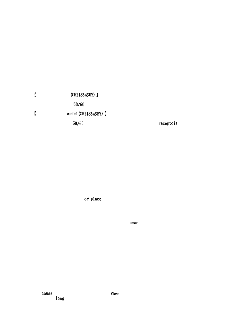
1
For USA model
(CM2186A3UY)
I
Use 100-120 volts
[
For European
Use 200-240 volts
50/60
Hz power line with safety grounded receptacle only.
model(CM2186A3EY) ]
50/60
Hz power line with safety grounded
receptcle
only.
Extremely high or low power voltage may cause trouble or may not give optimum
performance.
DO NOT USE AT WRONG PLACE
To prevent shock or fire hazard, DO NOT expose this unit to rain or moisture.
This unit is designed to be used in offices.
DO NOT subject the unit to
vibrations. dust or corrosive gases.
KEEP IN A WELL VENTILATED PLACE
Ventilation holes are provided on the cabinet to prevent the temperature from rising.
DO NOT cover the unit
ollplace
anything on top of the unit,
AVOID HEAT
Avoid placing the unit in direct sunshine or
near
heating appliance.
BE CAREFUL OF MAGNETIC FIELDS
Do not place a magnet, speaker system, printer, floppy disc drive or anything which
will generate magnetism near the unit,
A magnetic field may cause blurred colors or
distortion of displayed pattern.
BE CAREFUL OF TREATING THE SURFACE
Do not wipe the surface of the unit using volatile liquids such as benzine or thinners,
or any chemically treated cloth: do not apply insecticide.
or cause peeling-off of the paint.
when
a vinyl product is kept in contact with the
It may damage the surface
surface a long time, stains may occur.
Page 6

LOCATION OF CUSTOMER CONTROLS
I
POWER SWITCH
POWER INDICATOR
‘v
x
DEGAUSSING
sw~~ci-i
Fig. 1. Front View
*CONTRAST AND BRIGHTNESS CONTROLS
Adjust the picture contrast and brightness on the screen.
,DEGAUSSING
SWITCH
This display is equipped with an automatic degaussing circuit (This circuit operates
when power is switched on).
If the display is turned horizontally and picture color
becomes un-uniform, push this switch to get fine color uniformity. Picture become
still after some ten seconds.
-h-
Page 7

\-
/
AC INLET
,o 0
I
R.G.B. SIGNAL INPUT
Fig.2. Rear view
GBR
o,o]
I'
I
SYNC SIGNAL INPUT
Page 8

[SIGNAL CABLE CONNECTION]
from signal gknerator
from signal generator
75OHM
termination switch
Fig.3. Signal cable
connec
tion
T-type connector
Fig. 4. SignaI cable connection (loop-through state)
SIGNAL CABLE CONNECTION
Connect
termination S1 must be switched to ‘75
R.G.B.
signal BNC connectors to the signal input.
DtM’
side (see
Fig.3).
Vhen
one display is used, the
lhen more than one display
are used at the sane tine (loop through state), see Fig.4 for connecting cabies.
For loop-through
S;P
DUSt
be switched to ‘High impedance’ side other than the last
(see
Fig.
3).
cpnnection,
T-type connectors (option) have to be used, and termination
monitor ln
-a-
line
Page 9

‘-
T i m i n g
C h a r t ( Recommended Signal
Horizontal
)
fH
T: Period
F: Front porch
1: Sync width
B: Back porch
D: Display time
Vertical
fv
T: Period
F: Front porch
W: Sync width
B: Back porch
D: Display time
Sync on Green mode
Video
C&B)
Green
with Sync.
63.9
11.92
60.0
16.67 mS
16.026 mS
I
D
2.36
0.047
0.047
0.547
I
kHz
,uS
d3
Hz
Ins
IDS
mS
(1065 H)
( 3
HI
( 3
II)
( 35
HI
(1024 H)
H/V Composite Sync. mode
Video
(R, G, B)
e----e
Sync.
Two types of
automatically Selectable. The priority is
lUUUL
F W
-> --
c-l
----v---m-
<
Sync.mode,
B
-- <-
H/V Composite Sync mode and Composite Sync on Green mode are
--mm
T
H/V
Composite Sync..
-9-
>
Page 10

INSTALLATION INSTRUCTION FOR ADJUSTMENTS
CM2186A
is adjusted to the standard signal timing at the factory as indicated
in “Timing Chart”
(~9).
When changing fH or display timing of input signal, the picture location or the picture
size on the screen needs to be readjusted, by qualified personnel.
If necessary, refer adjustment to your dealer.
READJUSTMENT PROCEDURE
1. Remove the lid for adjustment (Refer to Fig.5).
2. Refer to the table
(~12).
To display appropriate picture on screen, adjust the “H-PHASE” and the “H-SIZE” with
plastic trimmer.
3. If necessary, adjust the other
VI&
shown in the table.
4. For detail, refer to the service manual.
Page 11

LID
SIDE VIEW
.
ADJUSTMENT DRIVER
ADJUSTMENTVR
Fig. 5
Removal of lid, readjustment method
-
11
\
-
Page 12

Adjustment shown below by qualified personnel is required when signals
other than the recommended signal are received.
Picture
Refer servicing to your dealer.
deviated
to
I
Picture deviated
Picture deviated
Page 13

For
European Model
FREIE UND HANSESTADT HAMBURG
CM2186A3EY
Zulassunssschein
Aufgrund 5 8 Abs. 2 dei Rantgenverordnung
5.114) wird der Firma Hitachi Sales Europa
burg 80, die Zulassung der Bauart fUr folgenden Storstrahler erteilt:
Gegenstand:
Bildriihre:
Hersteller:
Maximale
Betriebsdaten:
I
Priifungsschein:
I
Die Zulassung ist befristet bis zum 8. Mai 1999.
Fur den
Strahlenschutz
die der Hochspannungserzeugung und -stabilisierung dienencen Uaugruppen des
Chassis.
Auflaae
aem §
Die
Ger6te
sind mit dem Kennzeichen
und mit folgendem Hinweis zu versehen:
“Die in
diesem GerOt
Die
Beschleunigungsspannung betr8gt
BESCHEINIGUNG DES HERSTELLERS I
I
1
Hiermit wird best8tiat.
Monitor
I.....,,. .I.,
(Gerlt
In Ubereinstimmung mit den
**..*>.
(Amtsblattverfiigung)
funkentsttirt
Der Deutschen Bundespost wurde das lnverkehrbringen
angezeigt und die Berechtigung zur
der Bestimmuagen eingeraumt.
. . . .
(Name des Herstellers I Importeurs)
CMZl86A%Y
. . . . . . . . . .
..I. .,.I. .,.,.,,. I..,... ,,.,,,..,.,,.,,,.,,,)I .,*.a
,Typ, Bezeichnung)
VDE
0871 B,
. . . . ..w I..,...........,.,. . . . . . . . . .
ist.
Hitachi Sales
w...........,,.
. . . . . . . . . ...*....* . . . . . . . . . . . . . . . . . . . . . . . . . . . . . . . . . . . . . . . . . . . . . . . . . . . . . . . . . . . . . . .
Farbmonitor
Mitsubishi
Type :
AFZlG9TA822 -TC25
Yokohama Works of Hitachi, Ltd., Japan
Hochspannung
Strahlstrom
Physikalisch - Technische Bundesanstalt
Nr.6.22-5765 vom 14. April 1989
wesentliche Merkmale sind die
10
RoV:
entstehende Rdntgenstrahlung ist ausreichend abgeschirmt.
da!3
der/die/das
Amtsblatt I63 Il984,
Ruropa Gmbll
Bestimmungen
...* w,,..,.... .,...,...L.,.............
HH
9/89
R6
(ROV)
vom 8.
Januar
Rungedamm
Bauirt
Type CM2186A,..
31,OkV
HH 918916
maximal
GmbH,
0,6mA
31,OkV.”
IMPORTEUIZS
. . . . . . . . . . . . . . . . . . . . . . . . . . . . . . . . . . . . . . .
der
Vfg. 1048
. . . . . . . . . . . . . . . . . . . . . . . . . . . . . . . . . . . . .
flberprufung
dieres Ger8tes
der Serle auf Einhaltung
1487
(BGBI
2,205O
Ham-
der Bildtihre und
,,I,,., *,.* ,.,,.,.,o,,.,., .,,.
.,,,,.,.,
. . . . . . . . . . .
.,,.
. . . . .
..“...I..... ,.,. I.......,........
.I
,,.,
-
13
-
Page 14

For Canada Model
NOTICE :
THISDIGITAL APPARATUS DOES NOT
EXCEED CLASS A LIMITS FOR RADIO
NOISE EMISSION FROM ii DIGITAL
APPARATUS AS SET OUT IN THE RADIO
INTERFERJZNCE
THE CANADIAN DEPARTMENT OF
COMMUNICATIONS.
AVIS :
LE
PaSENT
N’lhET
PAS DE BRUITS
REGULATIONS OF
APPAREIL
DfiPASSANTLES
AUXAPPAREILSNUM&IQUESDE
(CM2186A3UY)
NUMIhIQUE
LIMITES
RADIOtiLECTRIQUES
APPLICABLES
CLASSEA
PR~~RITE~DAN~LER&GLE~NTSUR
LE
BROUILLAGE RADIOtiLECTRIQUE tiDICTl?
PAR LE
MINIST&RE
DES COMMUNICATIONS
DUCANADA.
Page 15

SPECIFICATIONS
COLOR DISPLAY TUBE . .
. . al-inch
(2OV)
90-degree, in-line gun trio-dot pitch,
0.31 mm with Anti-Reflection panel
PHOSPHOR TYPE * . * * * .
POWER INPUT VOLTAGE
POWER
INPUT SIGNAL l - - m -
CONSUHPTION *
p22
. * l 120V range.. , . , AC
220V
.
’ * 12OW typ. (135W Dex. 1
* R
G. B. anilog input
-
. , . . . AC 200-240 volts (Europe)
ra.nge
100-120
volts (USA, Canada)
(BNC
terminals)
0.7 Vpp (positive) at 75 fi terminated.
SYNC. SIGNAL - . - . * -00.3 Vpp (negative) Composite sync on Green or Composite
sync,
‘lTL
level, Negative
SCANNING FREQUENCY * * * * Horizontal : 64
kHz
(RECOMMENDED)
Vertical : 60 Hz
HAXIMUH
RESOLUTION . .
DISPLAY SIZE * . . . . .
MISCONVERGENCE * * * . . . 0.3 mm
c()mf&s
. . . . . . . .
- -
1280 dots
u
350 mm wide X 280 mm high with recommended timing
0.5 mm max. ; corners (0.3 mm
*contrast,
(H)
X 1024 lines
max. ;
center
(V)
typ.)
brightness, degaussing SW
DIMENSIONS . . * . . .
WEIGHT * * a l l * * . * *
-
. 488(W) X
30.5kg
approx
467(H)
X
517(D)
mm
(incl. tilt/swivel stand)
*
Specifications are subject to change without notice for performance improvement.
-15-
Page 16

 Loading...