

Page 1

MODEL
1
CM2073A
(For Europe)
OPERATING GUIDE
Page 2

GENERAL
The
CM2073A
CADKAMKAE
is an ultra high resolution colour display designed for
engineering and workstation use.
CM2073A’
*Ultra-high resolution
*Sharp focus by in-line high resolution CRT 20 inch
0.311~1
*Bright colour picture with low distortion due to the use of an
efficient high performance deflection yoke.
*Compact chassis and low power consumption with switching power
supply and self converging system.
*Ergonomically designed cabinet with tilt and swivel stand.
2
dot pitch matrix.
s key features
-
up to 1280 dots X 1024 lines
are=
(19V)
with a
Page 3

w
Bescheinigung des Herstellers / Importeurs
Hiermit wird bescheinigt,
(Gerat,
Typ, Bezeichnung) in
Amtsbl.
(Amtsblattverfugung)
Der Deutschen Bundespost wurde das Inverkehrbringen dieses
Gerites
Einhaltung der Bestimmungen
Hitachi Sales Europa
WPOWER
This colour display is designed to operate on
AC. Insert the power cord plug into a
grounded outlet.
DO NOT CONNECT THE DISPLAY TO OTHER THAN THE SPECIFIED VOLTAGE.
Never remove the back cover of the display as this can expose you
to very high voltage and other hazards. If the display does not
operate properly, unplug the display and call your dealer.
NOTE :
163/1984
angezeigt und die Berechtigung zur
Vfg.
SOURCE
1. This colour display is equipped vith a three-vire type
plug. This plug will only fit into a grounding-type
power outlet. This is a safety feature, do not defeat
the safety purpose of the grounding-type plug.
da13
1046/1984
funk -
GmbH
der / die / das Farbmonitor, Model1
ubereinstimmung
der Deutschen Bundespost
entstdrt
ist.
eingertiumt.
mit den Bestimmungen der
uberprtifung
220/240
220/240
volts 50 Hz safety
der Serie auf
volts 50 Hz,
CM2073A
2. If the power cord or plug is damaged or frayed, replace
it.
3. Do not overload wall outlets or extension cords as this
can result in fire or electric shock.
TO PREVENT SHOCK OR FIRE HAZARD,
DO NOT EXPOSE THIS DISPLAY TO
RAIN OR MOISTURE..
3
Page 4

CAUTIONS ON USE
CAUTIONS ON THE SUPPLY
When the power voltage is
extremely high or low, it may
cause trouble or it may not give
optimum performance. Consult your
dealer at that time.
KEEP IN A WELL VENTILATED PLACE
Ventilation holes are provided in
the cabinet to prevent the
temperature from rising. Do not
place the unit in a place badly
ventilated or cover the unit with
materials such as clothes.
VOL-
KEEP WATER OUT
When water of liquid enters the
set,
the unit. Immediately pull the
plug out and contact your dealer.
it becomes dangerous to use
HIGH TEMPERATURE CAUSES TROUBLE
Avoid placing the unit in direct
sunshine, near a heating
appliance.
Page 5
WHEN BEHAVIOUR IS ABNORMAL
When any abnormal sound, odour or
smoke is generated, push the
power switch off, pull the power
plug out from the socket and
contact your dealer.
CAUTIONS
TREATING THE SURFACE
Do not wipe the surface of the
set using volatile liquids such
as benzine or thinners, or any
chemically treated cloth; do not
apply insecticide. It may damage
the surface or cause peeling-off
of the paint. When a vinyl
product is kept in contact with
the surface for a long time,
stains may occur.
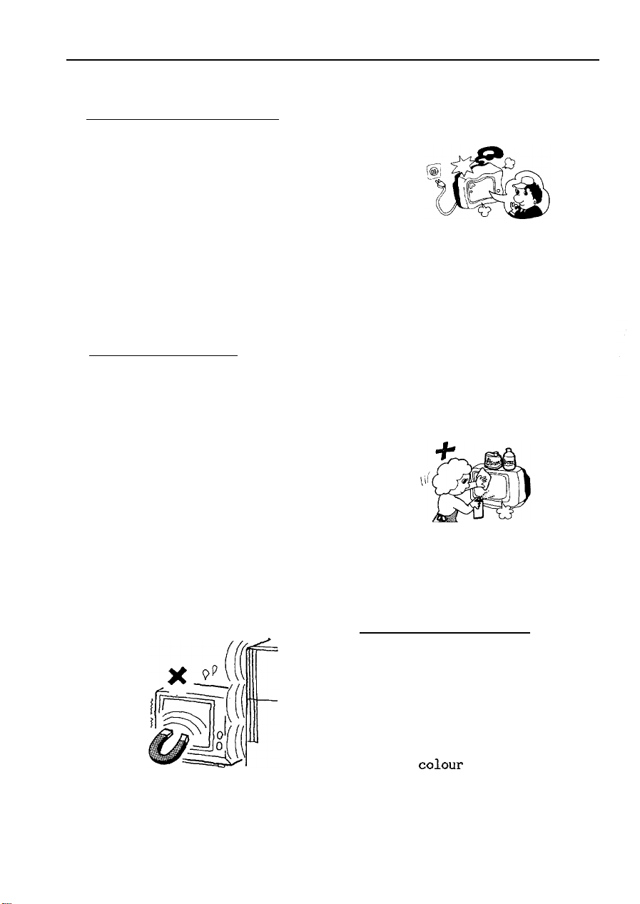
BE CAREFUL OF MAGNETISM
Do not bring materials which
generate magnetism, such as a
magnet, printers, floppy discs,
or transformers etc. nearby: the
set may be affected by magnetism,
causing
colour
disturbance or
picture distortion etc.
5
Page 6

LOCATION OF CUSTOMER CONTROLS
[FRONT
vmwl
Fig. 1
BRIGHTNESS CONTROL
CONTRAST CONTROL
/
/
DEGAUSSING SWITCH
POWER SWITCH
“0"
means power on.
“I" means power off.
\
POWER INDICATOR
(This illuminates
when power is on.)
CONTRAST AND BRIGHTNESS CONTROLS
These may be adjusted by releasing the push in/out rotary controls.
DEGAUSSING SWITCH
This display is equipped with an automatic degaussing circuit (This
circuit operates when power is switched
horizontally and picture colour becomes un-uniform, push this switch
to get fine colour uniformity.
seconds.
Picture may become still after some ten
on).
If the display is turned
6
Page 7

[REAR
VIEW]
R.G.B. SIGNAL INPUT
FUSE
F901
AC CORD INLET
1
I
SYNC SIGNAL INPUT
I
175 OHM TERMINATORS
Fig. 2
(Some displays
are not equipped
with this sync.
input and 75 OHM
terminator.)
FUSE
F901
Please always use
4A/25DV
IEC type fuse, (contact service personnel).
SIGNAL CABLE CONNECTION
Connect R.G.B. signal BNC connectors to the signal input. When one
display is used, the 75 OHM terminator must be connected to
yout"
BNC
connector (see Fig.4 ). When two more displays are used at the same
time (loop through state) see Fig.6 for connecting cables.
7
Page 8

[SIGNAL
CABLE CONNECTION)
from signal generator
from signal
generator
75 OHM terminator
(must be connected)
Fig. 3 75 OHM terminator connection
from signal generator
,,,,/
/$TK~-'-j
(side view)
I
Fig. 6 2 more displays case
(loop through state)
to next display
Fig. 4 cable connection
(rear view)
signal cable
v
Fig. 5 terminator not connected
a
Page 9

VIDEO INPUT SIGNAL TIMING
CHART-
1. SEPARATE SYNC
t
1
*
R.G.B. signal (analogue)
(HORIZONTAL)
I i.S ’
p-20.47-
Fig. 7
2. SYNC. ON
Green Signal
**********in case of
L
(unit:
4
GREEN**********in
pS)
case of
CM2073AME-S-315
(VERTICAL)
_ .---
(R.G.B.)I
r;/;ELHy-
p813H-d
Fig. 8
CM2073A-312/315
CM2073AME-S-315
u
(unit: H)
I
/-f11.5c120.47pJ
(unit:
pS)
I
J-
(unit: H)
Fig. 9
9
Page 10

INSTALLATION INSTRUCTIONS
FOR DEALERS
ADJUSTMENTS FOR THE
This document lists the
the dealer. Other
and should not be attempted by untrained personnel.
The
CM2073A
line rates of nominal
on the green video
without D.D.C. (Dig:ital Dynamic Convergence) and models with internal
timing to preferred video driving boards.
Before any of the adjustments below are attempted, please ensure that
the model has been chosen appropriately from the options listed on
page 16 of the operating guide.
The adjustments listed in this note permit some deviations from this
table, but it is important that the most appropriate model be chosen.
comes in various configurations including displays for
CM2073A
ad.justment.s
drive9
ON INSTALLATION
ad.iustmcnt
50kHz
and
separate line synchronisation, with or
fcat,rlrrs of thr
exist
which are
60kHz
operations, line synchronisation
20738
available to
not readily accessible
.
,'
1
ADJUSTMENTS
Before attempting any of the following adjustments, the display should
be powered up for a period of 15 minutes prior to the
1. Switch on the
to the power switch comes on, If it does not;
a>
Check power source and connections
b)
Check fuse
c)
Call a service engineer
power9
noting that. the green power indicator adjacent
ad-justment.
10
I
.:.
Page 11

*
..*
.+l
2. Advance the contrast and brightness controls fully clockwise.
3. If no picture appears check the video drive and source connections
particularly green for sync on green models or composite sync if
there is a separate line. No picture will appear without the sync
signal.
4. When a display appears note the stability of the displayed image.
If it is not stable or it is displayed from centre, switch off the
mains supply
and
remove outer plastic case only by removing four
screws from the rear panel and two screws from the centre portion.
It may be convenient to remove and replace signal and power cables
at this stage, since they pass through the rear cover. See
SCREW
i
BACK COVER
COVER
Fig.10.
BOTTOM COVER
”
SC ii E L”J
Fig. 10
1
11
Page 12

5. Power up and adjust (if necessary) the horizontal hold control with
plastic trimmer (Fig.ll). Note that it is important that a plastic
trimmer is used. Otherwise the adjustment could result in a short
circuit and breakdown of display.
,
.
6. Adjust vertical hold control (if necessary) with plastic trimmer.
7. Either of the two previous controls should stabilize the picture.
If not, call the service engineer.
8. With a stable picture, note the size and its position of the
picture. Any adjustment shoud be made in the following sequence.
Horizontal Centre
Horizontal Size
Vertical Centre
Vertical Size
1
!
Figs 11 and 12.
i
B CUTOFF G CUTOFF R.CUTOFF
G.
E
EKG
\
EKG /R EKG
/
Q
H.
PHASE II
/.
41 \
u i
H SIZE H
12
\
CENT
Fig. 11
I
I
Fig. 12
Page 13

9. With the previous adjustments complete YOU shoud now have a stable
picture correctly
centred.
Check the left and right hand edges of
the picture for clarity. If any corruption is present, it is
necessary to adjust the horizontal phase until both extremities are
clear. If adjustment is necessary,
the horizontal centre and size
may need further adjustment.
10. Display a picture that contains vertical lines at both right hand
and left hands of the screen. If necessary, adjust the pin cushion
control to make the lines straight.
11. Display a picture that contains a multiplicity of horizontal lines
with constant spacing. If the lines are not displayed with equal
spacings adjust the vertical linearity. If this adjustment is
necessary, some readjustment of the vertical centre and size may be
required.
12. Display a picture that contains a large white area and check that
the displayed image is white. If it is not, an unqualified engineer
shoud not attempt to adjust the
colour
drives or background to
compensate. A qualified engineer must first determine that the
black level pedestal is correctly positioned before any such
adjustment is considered. This work involves further dismantlement
of the chassis.
5;
13. If in doubt or experiencing difficulty with the adjustments
detailed, contact the supplier of the equipment.
c
14. In all of the above adjustments, ensure that the viewable
displayed image does not exceed a displayed field of 380 mm X
270
mm.
Finally, power down and replace covers and centre case portion first.
Turn brightness and contrast controls to their normal operating
positions.
13
Page 14

FREIE
UND
ARBEITS -
AMT FUR ARBEITSSCHUTZ
Gesch -Z AS 23!FBA Ro
(Bei
Beantwortung
bttte anqehen)
HANSESTADT
UND
SOZlALBEHkDE
Fernsprecher
HAMBURG
29188 3135 (Durchwahl)
Pulassungsschein HH
Aufgrund 5 7 Abs. 2 der Rentgenwerordnung worn
(RGBl.
I S.
173)
wird der Firma
Hitachi Sales Europa
GmbH.,
Rungedamm
22/86
Ro
2,205O
01. M&z 1973
Hamburg 80 die
Zulassung der Bauart fijr folgenden Stijrstrahler erteilt:
Art
TOP
Hersteller
Farbmonitor
CM2073A
Yokohama Works of Hitachi Ltd., Yokohama,
Japan
Bildrijhre
Betriebsdaten
Prlfungsschein
Hitachi
Hochspannung 31
Strahlstrom
Physikalisch-Technische Bundesanstalt Nr.
M48JLK22X
kV
0.6mA
S416 Vom 01.08.1986
Die Zulassung ist befristet bis zum 11.08.1996
Fiir den Strahlenschutz wesentliche Merkmale:
a) die Bauart der
Bildr8hre,
b) die der Hochspannungserzeugung und -stabilisierung dienenden
gruppen des Chassis.
Auflagen
$j
Gemi%
1,
Die Gerate sind einer
beztiglich der
8 Abs. 1 der
lagen
werbunden:
fiar
den Strahlenschutz wesentlichen
R6V
wird die Zulassung mit folgenden
Stkkprtifung &raufhin zu
unterziehen, ob sie
Me&male
Bauartzulassung entsprechen. Die Prufung mufi umfassen :
a)
Kontrolle
b)
Dosisleistungsmersunq nach ntiherar .4nqabe der Zulassungshehorde.
Die Ergebnisse der
der Gertite mugeordnet.
regelm&ig
der Hnchspannunq an ledem
Doslsleistungsm?ssung slnd,
aufzuzeichnen und der Zulassungsbehorde
einmusenden. Die
Zeitr
ernzelnen
Garat
den Werstellnummern
aume hierfur werden gesondert
bestimmt.
6.22-
Bau-
Auf-
der
14
Page 15

Die Zulassungsbehorde ist berechtigt, einzelne Gerate
Auswahl anzufordern,
wesentlichen Merkmale zu uberprufen oder uberprufen zu
Die Gerate sind auf Verlangen im Originalzustand anzuliefern und
angemessene Zeit zur Verfugung zu stellen.
2. Die Herstellung und die Stuckprufung sind durch einen von der
Zulassungsbehorde bestimmten
3. Die Gerate sind mit dem Kennzeichen.
zu
versehen
“Die in
abgeschirmt. Beschleunigungsspannung maximal 31
4. Jedem Erwerber eines Gerites ist ein Abdruck des Zulassungsscheines
auszuhindigen, auf dem das Ergebnis der Sttickprtifung (Auflage 1)
bestatigt sein
Jedem Gerat ist ferner eine Betriebsanleitung beizufiigen, die den in
Auflage 3 genannten Hinweis enthilt.
Hinweis
UnsachgemaBe
Auswechseln der Bildrohre, konnen dazu
erheblicher Sterke auftritt. Ein so verindertes Gerat entspricht nicht
mehr dieser Zulassung und darf infolgedessen nicht betrieben werden.
Aufgrund der durchgeftihrten
Stiickprufung wird hiermit
bestatigt,
bezuglich der
schutz
wesentlichen Merkmale
der Bauartzulassung entspricht.
sowie mit einem Hinweis folgenden Mindestinhalts :
diesem
mu&
fur
den Benutzer des
Eingriffe, insbesondere Verandern der Hochspannung oder
da6 dieses Gerat
fur
den Strahlen-
urn
das Vorliegen der fur den Strahlenschutz
Sachverstandigen
HH 22/86
Gerat entstehende Rontgenstrahlung ist ausreichend
Gera’tes
Ro
fiihren,
uberwachen zu
dab Rontgenstrahlung in
(Dienstsiegel) WZ. Bohnenkamp
nach
lassen.
kV.”
eigener
lassen.
15
Page 16

SPECIFICATIONS
20
COLOUR DISPLAY TUBE.........
PHOSPHOR
POWER INPUT
POWER
INPUT SIGNAL................
SYNC. SIGNAL................
MAXIMUM
MISCONVERGENCE..............0.3
CONTROLS
DIMENSIONS..................506(W)X415(H)X542(D)
WEIGHT
TYPE...............P22
VOLTAGE.........230V range.....AC 200/220/230/240
CONSUMPTION...........150W
RESOLUTTON..........1280 dots(H)X1024
..................
......................
inch(l9V)
trio-dot pitch,
panel
R.G.B.
analog
In case of loop through state, terminated
Signal
O.QVp-p(negative)
mm max ; all over (with DDC)
0.3
mm max ; center
0.5 nun max ; corners
..contrast.
35 kg
90 degree, in-line gun
terminated by 75 ohm position.
at the high position.
timing.....shown
brightness,
(incl.
tilt/swivel stand)
0.31mm
with non-glare
input(BNC
separate/sync on green
terminals)
below
lines(V)
)
(without
degaussing SW
mm
DDc)
volts
SIGNAL TIMINGS
rl
w!
4602091
CM2073A-301
CM2073A-302
Note:
DDC
means Digital Dynamic Convergence.
SCANNING FREQUENCY
I
00
48.8kHz 1 6OHz
63.9kHz
I I
159.5ktIz / 70.4Hz
1 (VI
60Hz
DISPLAY
AREA
360nxn(H)
X27Oimn(V)
340mm(H)
X27Omm(V)
345mm(H)
x27Omm(V)
DISPLAY
TIME TIME
H:16.02cts Hz4.4~~ 0
v:15.7ms
H:ll.Sps
V:16.Oms
Hz12.8~~
V:13.4ms v:o.77ms
Printed in Japan YN-M(S)
RETRACE
DDC
v:o,92ms H:307/~s
0
V:0.64ms
H:4.0@s
0
 Loading...