

Page 1

COLOUR MONITOR
CM 1786M-AD
17
MVX
VddSupersCan
User’s Manual
17s
:
_
READ THE
KEEP THIS
INSTRUCTION INSIDE
USER’S
MANUAL FOR
CAREFULLY.
FUTURE REFERENCES.
Page 2

Page 3

_.’
_.
%,
” ;_’
.,
.:
),. ,
T.
,
;~’
,
,.,. ’
).
‘.,
T,.
,’ ,:
Page 4

Page 5

For U.K. Customers
THIS PRODUCT IS SUPPLIED WITH A TWO PIN MAINS
PLUG FOR USE IN MAINLAND EUROPE. FOR THE U.K.,
PLEASE REFER TO THE NOTES ON THIS PAGE.
Note:
Electrical Connection
Your monitor requires an electrical supply of 240 volts - 50 Hertz and should
be protected by a 5 amp fuse. Your equipment is supplied with a plug
incorporating a 5 amp fuse fitted to the mains lead. If the plug that is fitted
to the equipment is not suitable for your socket outlet, it must be cut off and
the appropriate plug fitted. The cut off plug should be disposed of, do not
insert it into a 13 amp socket to prevent the hazard of electric shocks. With
plugs not incorporating a fuse, the circuit must be protected by a 5 amp fuse.
Warning: This equipment must be earthed.
Important
Your equipment is supplied with a mains lead, the wires of which are
coloured
Blue - Neutral, Brown - Live.
in accordance with the following code: Green and Yellow - Earth,
Green & Yellow
to Earth
Blue to Neutral
Brown to Live
Fuse
Cord Clamp
Page 6

As the
colours
of the wires in your mains lead in this equipment may not
correspond with the markings identified with the terminals of your plug,
proceed as follows:
The wire which is coloured Green and Yellow must be connected to the
terminal in the plug which is marked with the letter E or by the symbol or
coloured Green or Green and Yellow.
The wire which is coloured Brown must be connected to the terminal which
is marked with the letter L or coloured Red.
The wire which is coloured Blue must be connected to the terminal which
is marked N or coloured Black.
The plug moulded on to the cord incorporates a fuse. For replacement, use
a 5 amp BS1326 fuse. Only ASTA approved fuses should be used. The fuse
cover / carrier must be refitted when changing the fuse. In the event of
losing the fuse cover / carrier, the plug must not be used until a replacement
has been obtained from your nearest electrical
colour
of the fuse cover / carrier is that of the coloured marks on the insert
stockist
and fitted. The
in the base of the plug.
Page 7

Important Safety
Instructions
1.
Read all of these instructions.
Save these instructions for later use.
2.
Follow all warnings and instructions marked on the product.
3.
Unplug this product from the wall outlet before cleaning. Do not use
4.
liquid cleaners or aerosol cleaners. Use a damp cloth for cleaning.
5.
Do not use this product near water.
Do not place this product on an unstable cart, stand, or table. The
6.
product may fall, causing serious damage to the product.
Slots and openings in the cabinet and the back or bottom are provided
7.
for ventilation, to ensure reliable operation of the product, and to
protect it from overheating; these openings must not be blocked or
covered.
The openings should never be blocked by placing the product on a bed,
sofa, rug, or other similar surface. This product should never be placed
near or over a radiator or heat register. This product should not be
placed in a built-in installation unless proper ventilation is provided.
8.
This product should be operated from the type of power source
indicated on the marking label. If you are not sure of the type of power
available, consult your dealer or local power company.
9.
This product is equipped with a three-wire grounding type plug, a plug
having a third (grounding) pin. This plug will only fit into a grounding
type power outlet. This is a safety feature. If you are unable to insert
the plug into the outlet, contact your electrician to replace your
obsolete outlet. Do not defeat the purpose of the grounding-type plug.
10.
Do not allow anything to rest on the power cord. Do not locate this
product where persons will walk on the cord.
If an extension cord is used with this product, make sure that the total
11.
ampere ratings on the products plugged into the extension cord do not
exceed the extension cord ampere rating. Also, make sure that the
Page 8

total of all products plugged into the wall outlet does not exceed 15
amperes.
12.
Never push objects of any kind into this product through cabinet slots
as they may touch dangerous voltage points or short out parts that
could result in a risk of fire or electric shock. Never spill liquid of any
kind on the product.
13.
Do not attempt to service this product yourself, as opening or removing
covers may expose you to dangerous voltage points or other risks.
Refer all servicing to service personnels.
14. Unplug this product from the wall outlet and refer servicing to
qualified service personnel under the following conditions:
l
When the power cord or plug is damaged or frayed.
l If liquid has been spilled into the product.
l
If the product has been exposed to rain or water.
l If the product does not operate normally when the operating
instructions are followed.
Adjust only those controls that are
covered by the operating instructions since improper adjustment
of other controls may result in damage and will often require
extensive work by a qualified technician to restore the product to
normal operation.
l
If the product has been dropped or the cabinet has been damaged.
l If the product exhibits a distinct change in performance, indicating
a need for service.
15.
Plug on the power supply cord is used as the disconnect device, the
socket-outlet shall be installed near the equipment and the shall be
easily accessible.
ii
Page 9

Federal Communications Commission (FCC) Statement
This equipment has been tested and found to comply with the limits for a
Class B digital device, pursuant to Part 15 of the FCC Rules. These limits
are designed to provide reasonable protection against harmful interference
in a residential installation. This equipment generates, uses, and can
radiate radio frequency energy, and if not installed in accordance with the
instructions, may cause harmful interference to radio communications.
However, there is no guarantee that interference will not occur in a
particular installation. If this equipment does cause harmful interference
to radio or television reception, which can be determined by turning the
equipment off and
interference by one or more of the following measures:
a
Reorient or relocate the receiving antenna.
a
Increase the separation between the equipment and receiver.
l
Connect the equipment into an outlet on a
to which the receiver is connected.
e
Consult the dealer or an experienced radio/TV technician for help.
Warning: A shielded-type power cord is required in order to meet FCC
emission limits and also to prevent interference to the nearby radio and
television reception. It is essential that only the supplied power cord be
used.
Use only shielded cables to connect I/O device to this equipment.
You are cautioned that changes or modifications not expressly approved by
the party responsible for compliance could void your authority to operate
the equipment.
on?
the user is encouraged to try to correct the
circuit
different from that
DOC compliance notice
This digital apparatus does not exceed the Class B limits for radio noise
emissions from digital apparatus as set out in the Radio Interference
Regulations of the Canadian Department of Communications.
DOC avis de conformation
Le present appareil
depassant
prescrites
MinistrCr des Communications du Canada.
les limites
dans le reglement sur le brouillage radioclectrique
numerique n’cmet
applicables
aux appareils numeriques de la Class B
pas de bruits radioelectriques
edict6
par le
Page 10

Low Radiation
Following the trend in the computer market toward low radiation, this
equipment has been tested and found to comply with Swedish regulatory
agency guidelines.
Research has shown that magnetic field emissions from computer monitors
may pose a very real health hazard to users, and this has become a great
concern to many people. Consequently, we are offering this low- radiation
display in response to the magnetic field emission issue.
The Swedish guidelines defines a level of induction and strength permissible
for magnetic field emissions. Magnetic field emissions for the equipment is
significantly lower than the Swedish guideline of 25 nT.
Liabiliiy Disclaimer
The product described in this manual is warranted in accordance with the terms of the
applicable manufacturer product specifications. Product performance is affected by
system configuration, software, application, customer data, and operator system control,
among other factors. While the product is compatible with the standards for which they
are advertised, product implementation may vary from user to user.
The suitability of this product for a specific application must be determined by the
customer and is not warranted by the manufacturer. This manual aims to teach the user
how to install and operate the product. The information contained herein is as accurate as
possible; however, updates may have been made since the time of printing. The
manufacturer assumes no responsibilities for damage incurred directly or indirectly from
errors, omissions, or discrepancies between the product and the manual.
Trademarks
Product and brandnames mentioned in this manual are for identification purposes only
and may be trademarks and/or registered trademarks of their respective holders.
Page 11
:::::::<::::<:
:::::q::::::.
:::::w
:.:::::::::&
$ggg
Table of Contents
This manual provides information needed to unpack, install, and operate
the monitor, and describes the generic version of the equipment.
Equipment manufactured after the publication of this manual may have
specifications other than those stated in this manual. Please contact your
dealer for verification.
Table of Contents
Section 1. Introduction
Section 2. Precautions
Section 3. Unpacking
Section 4. Getting Acquainted
4.1. User Controls and Indicators
4.2. Display Adjustment Controls
4.3. Preset and User Modes
4.4. Installing the Tilt and Swivel Base
Section 5. Installation Instructions
Section 6. Advanced Display Adjustment
6.1. Using the < Function > Button
6.2. Making Color Adjustments
6.3. Making Pincushion Adjustments
6.4. Enabling /Disabling the Power Saving Function
Section 7. Specifications
7.1. CRT (Cathode Ray Tube)
7.2. Input Signals
...........................
7.3. Deflection Characteristics
7.4. Recommended Resolution
7.5. Display Size
7.6. Operator Controls
7.7. Power Requirements
...........................
.........................
......................
7.8. Dimension(WxHxL)
7.9. Signal Connector
7.10. Power Management
........................
........................
..................
..................
......................
...............
.................
...................
................
.......
...................
....................
...................
.....................
.16
-16
.16
.16
.17
.17
.17
.6
.6
8
.9
12
13
14
14
16
17
17
1
Page 12

Section 8. Power Management Utility
8.1. Using Power Management under DOS
8.2. Help Menu
............................
............
8.3. Power Management for Windows ................
18
.19
19
Notes to users: The power management utility diskette contains the files
OFFH.COM and
OFFHSCR
which allows the user to set the idle time
required before the monitor goes into the power saving mode. This software
is not required to operate the monitor as a display device or to comply with
Energy Star and DPMS, but is a special offer to allow you to take advantage
of power saving features without the need of a DPMS compliant system.
While efforts have been made to ensure compatibility, it can not be
guaranteed that this package will work as it is described in the operator’s
manual with all PCs and video cards. The manufacturer makes no claim or
warranty on this package.
:
2
Page 13

:::$$&;::
::::::).:.:$>
~~ Section
1
Introduction
The 17MVX Value I
SuperScan
17s are two microprocessor based,
intelligent scanning 17-inch color monitors best suited for various
applications from word processing to spreadsheets to
CADKAE.
Their
microprocessor intelligence provides a wide range of signal compatibility
and allows easy adjustment of screen configurations with various display
modes.
Some of the 17MVX Value I
l Automatically scans the horizontal frequency from 30 to 64 KHz and
SuperScan
17s features are as follows:
the vertical frequency from 50 to 100 Hz.
l The monitor is equipped with a power-saving feature that automatically
powers down the monitor after a user-defined period of inactivity. The
power saving feature is compatible with VESA DPMS-compliant
display cards.
l All parameters in each of the display modes reside in the
microprocessor-based control system. Settings are built in for existing
VGA standards, super VGA (800 x600), 8514/A (1024x768 interlaced),
1024 x 768 non-interlaced, and 1280 x 1024 modes.
l Front panel controls to adjust the H-size, H-phase, V-size, and
V-position in each display mode according to user preference. Each
new setting is stored and recalled each time a mode change is effected.
l
Color display adjustment system allows users to individually adjust red,
green, and blue colors on screen.
l The power supply may be operated within a 100 to 240 VAC range and
the detachable power cord meet all recognized international
requirements.
3
Page 14

::::g$:g
. . . . . . .. . . . . .
.
$$$$$J
$$g Section
2
Precautions
To prevent injury to yourself and/or damage to the monitor, please read and
adhere to the following suggestions:
1.
Never connect the monitor to any outlet with a voltage or frequency other
than that indicated on the monitor backplate.
2. Never connect the monitor to direct current.
3. Do not open the monitor cabinet.
4. If the monitor is not operating properly, contact your dealer. DO not
open the monitor housing under any circumstances.
By opening the monitor housing you will expose yourself to high voltage
and possible severe electrical shocks.
5.
Do not place the monitor under direct sunlight, near heating appliances,
or in areas with excessive light and moisture.
6. Keep the monitor in a well-ventilated area and keep the monitor
ventilation holes free from obstructions.
7.
If any abnormal sound, smoke, or odor comes from the monitor, unplug
the monitor’s power cord immediately and contact your dealer.
8. Do not rest the monitor or any other heavy objects on the power cord.
A damaged power cord can cause fires or electrical shocks.
9.
Keep the monitor away from high capacity transformers, electric motors,
and other strong magnetic fields.
4
Page 15

Unpacking
Carefully unpack the monitor from the shipping carton and avoid using
sharp objects in opening the carton. Save the packing materials and carton
for use in reshipping the monitor in the future.
The monitor comes with the tilt and swivel base detached. Please follow the
instructions contained in Section 4.4 to install the tilt and swivel base.
Usqr’s
manual
Usqr’s
manual
b
Power management utility disk
i
Fig. 1. Please check that all of the above items are present once you have
unpacked the monitor.
5
Page 16
$$$$$g
:::::::::::::::
j#@ Section
4
Getting Acquainted
4.1. User Controls and Indicators
1.
Power Switch. A push-on/push-off type switch used to turn the monitor
power On or Off.
2.
Power-on indicator. This LED lights green when power is applied to the
monitor.
3. Brightness Control. This control allows adjustment of overall picture
brightness to a comfortable viewing level in varying degrees of room
lighting. Press the corresponding < + > or c - > buttons to change the
overall picture brightness.
4. Contrast Control.
preferred contrast level.
buttons to change the overall picture contrast.
This control is used to adjust
Press the corresponding < + > or <- >
the
display to the
4.2. Display Adjustment Controls
The monitor contains preset display information on all of the available
display modes and no user-adjustments are normally required. However,
the front panel push buttons may be used for display adjustment in any of
the display modes if necessary.
Once set, the settings will be automatically saved and recalled each time a
mode change is effected.
When shipped from the factory, the front panel push buttons may be used
to perform the following adjustments:
1. H-phase. Used to adjust the proper horizontal display position.
2.
H-width. Used to adjust the picture width to the desired level.
6
Page 17
Contrast
Brightness
Power-on LED
Fig. 2. Frontpanel controls.
3. V-size. Used to adjust the overall picture to the preferred height.
4. V-shift. Used to adjust the proper vertical display position.
5. Reset. Used to return the display parameters of the current display
mode to the factory default settings. The LED display blinks two times
indicating that the settings have been changed to default.
The Reset button will only recall the factory defaults of the display mode
currently in use. The other display modes are not affected.
6. Function. Press and release the < Function > button to set the front
panel controls to the alternate mode for picture geometry and color
adjustments. Refer to Section 6.1 for more information on the use of the
c
Function > button.
7. Degauss. This control eliminates the built-up of stray magnetic fields
which affect the purity of screen colors,
focus:
and convergence.
8.
Tilt. Use a small screwdriver to rotate this control clockwise or counter-
clockwise for picture rotation (tilt) adjustment.
7
Page 18

I
--
H-width
Reset
1
Fig. 3. Press down on the release tab to access the display adjustment
controls.
4.3. Preset and User Modes
The monitor incorporates 10 preset modes and four user modes. The preset
modes are defined as follows:
Display mode
VGA
VGA
VGA
SVGA
8514/A 1024 x 768 35.5 KHz, 87 Hz
VESA
VESA
VESA
VESA
CAD I CAE
Resolution
640 x 350 31.5 KHz, 70 Hz
720 x 400 31.5 KHz, 70 Hz
640 x 480 31.5 KHz, 60 Hz
800 x 600 35.2 KHz, 56 Hz
640 x 480 37.8 KHz, 72 Hz
1024 x 768 48.9 KHz, 60 Hz
800 x 600 48 KHz, 72 Hz
1024 x 768 57 KHz, 70 Hz
1280 x 1024 64 KHz, 60 Hz
fH, fV
Polarity
+,
-
-9
+
-3
-
8
Page 19

4.4. Installing the Tilt and Swivel Base
The monitor is designed to be mounted to the tilt and swivel base with which
it was shipped. To install the tilt and swivel base, proceed as follows:
1.
Place the monitor upside down on a smooth and stable surface.
2.
The monitor bottom side contains mounting holes for the tilt and swivel
base. These holes are represented as shaded areas in Figure 4.
3. Make sure that the claws on the tilt and swivel base slips into their
corresponding mounting holes on the monitor bottom surface. Push the
tilt and swivel base all the way toward the front of the monitor until it
snaps into place.
Fig. 4. Installing the tilt and swivel base.
9
Page 20

. . .. . . .. .
..A.
:;:::::::::;:::
::::::::::::y:
jj$$jj Section
5
Installation Instructions
The monitor can be used with any IBM personal computer or compatible
equipped with display cards capable of any of the following modes: VGA,
super VGA, 8514/A, non-interlaced 1024 x 768, and 1280 x 1024 modes.
Proceed to install the monitor as follows:
1. Turn off the power to the monitor, the computer system, and other
attached devices.
2.
If the display adapter is not yet installed in the computer system, install
it according to the instructions accompanying the display card.
3. Connect the video cable on the monitor to the
display adapter and tighten the fastening screws.
Fig. 5. Rearpanel connectors.
Spin
output of the
adapter
Page 21

When connecting the video cable, make sure that the video cable
D-connector aligns with the video adapter connector. Do not force the
cable onto the adapter in the wrong direction or the video cable may be
damaged.
Fig. 6. Aiign the video cable D-connector with the video adapter connector.
Connect the monitor AC power cord to a properly grounded AC outlet.
4.
5.
Turn the monitor’s power on.
6. Turn the computer’s power on.
Note: A quick power on-off sequence may cause problems with the
monitol.
After powering off the monitor, wait for at least three (3)
seconds before turning on the power again.
7. With the screen displayed, adjust the Brightness and Contrast controls
as necessary for best viewing comfort.
!
11
Page 22
. ... .,:.:.:.:.:
::::::.:.:.:.:.
~
Section
5
Advanced Display Adjustment
This section explains the features and functions of the monitor display
adjustment systems. It includes a list of the front panel alternate modes for
ready reference as well as a step-by-step guideline on how to adjust picture
geometry, vertical and horizontal picture linearity, and color display.
Note: The manufacturer does not recommend that users perform these
adjustments all by themselves.
experience may be required
problems are encountered while adjusting the service controls, just press
<Reset
> and start all over again.
6.1. Using the c Function > Button
Press the <Function > button and either of the Brightness and Contrast
controls to perform picture geometry and color adjustments.
Specific test patterns and some service
toperfonn
some of these adjustments. If any
The available picture geometry and color adjustments are listed as follows:
Press these buttons: To change to these
El+iIEi
El+m?i
El+m
12
alternate modes:
User-Defined Color
Setting 1
User-Defined Color
Setting 2
Pincushion control
To perform the
following functions:
Red driver
Green driver
Blue driver
Red driver
Green driver
Blue driver
Pincushion
Page 23

6.2. Making Color Adjustments
The monitor color display adjustment system includes one factory default
color setting and two user-defined color settings.
The following table shows how each of the color settings may be selected:
To select:
User-Defined Color
Setting 1
User-Defined Color
Setting 2
1..
Use the corresponding c + > and < - > keys to change the individual
Press:
<Function> -
c Function > -
m
m
To perform the
following adjustments:
Red driver
Green driver
Blue driver
Red driver
Green driver
Blue driver
red, green, and blue colors according to individual preference.
Every adjustment made under either of the user-defined color settings
will be automatically saved.
2. After adjustments are made, press < Function > to exit.
Note: Adjustments you make in color affects the entire image. For
example, any decrease in red will affect the overall intensity of the image.
Should you encounter any problems while making color adjustments,
simply reset to the factory defaults and start all over again.
To switch between the factory default and either of the user settings:
1. Press either <Function> + m or <Function> + IO to select
the desired set of user-defined color setting.
2. Press
.
Q
The current user setting is switched to the factory defaults
without being erased. Press <Function > to exit.
3. To select the user setting again, press either <Function> + IV or
<Function> + m .
13
Page 24

To reset the user settings to the factory defaults:
1. Press either < Function> + m or -z Function> + m to select
the user-defined color settings you want to reset.
2. Press <Reset
factory defaults.
3. Press < Function > to exit
This user-defined color setting is now reset to the
>.
6.3. Making Pincushion Adjustments
The pincushion adjustments allows you to make the left and right sides of
the picture straighter by moving the upper and lower corners of the display
in or out while holding the sides fixed.
1. Press < Function > + la for pincushion adjustments.
2. Use the a and [ keys to make the corresponding adjustments.
3. After adjustments are done, press <Function > to exit.
To reset to factory default:
1. Press < Function > + m for pincushion adjustments.
2.
Press < Reset >. This brings the user back to the factory settings of the
display mode currently in use.
3.
The LED display blinks two times indicating that the settings have been
changed to default.’ Press c Function > to exit.
The <Reset > button will only recall the factory defaults of the mode
currently in use; settings on the other display modes will not be affected.
4.4. Enabling / Disabling the Power Saving Function
The monitor is equipped with a power-saving feature that automatically
powers down the monitor after a user-defined period of inactivity. The
power saving
cards. The power-saving feature is on by default.
14
feature
is
compatible
with VESA DPMS-compliant display
Page 25
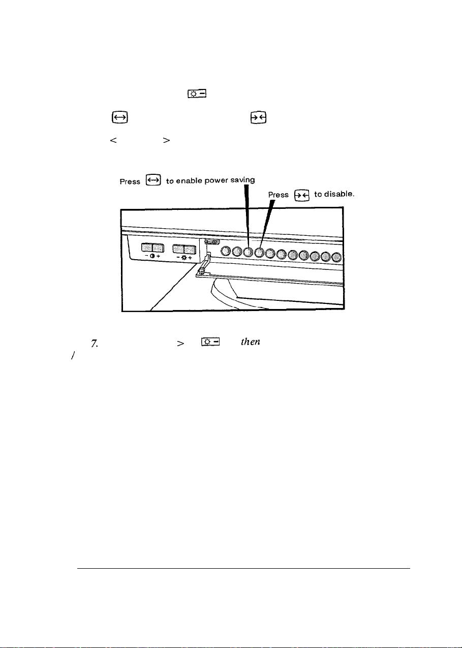
To turn off the monitor’s power-saving feature, proceed as follows:
1. Press <Function> + m .
2. Press @ to enable power saving; @ to disable.
3. Press < Function > when done.
L3ZB
and
thea
Fig. 7. Press <Function > +
I
disable the power-savingfeature.
the corresponding keys to enable
Page 26
.
. . . .
. . . . .
..y.
::::>:::::::::
::::.:.:.:.:.:.
j@$@ Section
7
7.1. CRT (Cathode Ray Tube)
Specifications
CRT size
Dot pitch
Face treatment :
: 17 inch
;
0.26 mm
dark glass, non-glare
7.2. Input Signals
Type
Video signal
Sync signals :
: analog
:
0.7
v,.,
separate sync, TTL level
7.3. Deflection Characteristics
H-frequency
V-frequency
Video Response : 75 MHz
: 30-64KHz
:
50 - 100 Hz
7.4. Recommended Resolution
a
640 x
480 J
60,72
Hz
l
800 x
600 /
56,72
Hz
l
1024
x 768, interlace
l
1024
x 768 /
l
1280
x 1024 / 60 Hz
60,70
’
Hz
7.5. Display Size
16
l
300 x 225 mm (default setting)
l
316 x 237 mm (full screen)
l Both display sizes dependent upon signal timing used
Page 27

7.6. Operator Controls
l Power On/Off l H-width
l Brightness
a
Contrast
l Reset button
l Degauss
l H-phase
l V-size
l V-shift
l Tilt
7.7. Power Requirements
l 100 to 240 VAC autorange
0 125 Watts maximum
7.8. Dimension (W x H x L) / Weight
l 410 x 400 x 445 mm
l 20.6 Kgs with tilt and swivel base
7.9. Signal Connector
Pin 1
Pin 2
Pin 3
Pin4
Pin 5
Pin 6
Pin 7
Pin 8
: Red
: Green
: Blue
: Ground
: Ground
: Red - ground
: Green - ground
: Blue - ground
Pin 9 : No connection
Pin 10 : Ground
Pin 11 : Ground
Pin 12 : No connection
Pin 13 : H-sync
Pin 14 : V-sync
Pin 15 :
No connection
7.10. Power Management
This monitor is fully-compliant with VESA DPMS and the EPA for Energy
Star. To take advantage of both display power management as well as
meeting Energy Star guidelines, the monitor must be used with
compliant display cards.
DPMS-
17
Page 28
:::::::::::::::
::::::::::::::i
~
Section
*
Power Management Utility
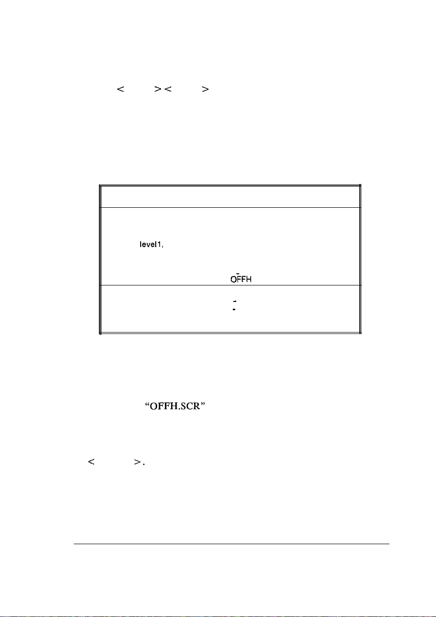
The power management utility diskette contains the files OFFH.COM and
OFFH.SCR which allows the user to set the idle time required before the
monitor goes into the power saving mode. It allows two levels of power
saving defined as follows:
Power Saving
Level 1
Level 2
Mode of Operation Power Consumption
Normal
Standby f suspend less than 15 Watts
Off
This is the default mode when the
monitor is first powered on or in use.
less than 8 Watts
8.1. Using Power Management under DOS
The interval required to enter Level 1 and Level 2 of power saving may be
set in either of two ways:
l
through the Power Management Utility menu
l
directly through the DOS command prompt
To use the Power Management Utility menu, type OFFH at the DOS
command prompt. The following menu appears:
Power Management Utility
Please enter the time interval required to enter
level 1 and level 2 of power saving. Time interval
for level 2 should be longer than level
Left, Right
Up, Down : to Move between levels
Hitachi
Level 1 : 2 min
Level 2 : 4 min
: to Set time intervals
Enter
: to Exit
Esc
: to Abort
1.
18
Page 29
To set the time interval via the DOS command line prompt, type:
l
OFFH < level1 > < level2
>
While in the power saving mode, press any key to return to the normal mode.
8.2. Help Menu
To invoke the help menu, type OFFH ? at the command prompt. The
following help menu appears:
Power Management Help Menu
Usage
OFFH
OFFH levell, level2 to set the time interval
OFFH V
OFFH R
Hot keys for DOS :
CTRL+ALT+H
CTRL+ALT+V
CTRL+ALT+O
CTRL +ALT + N
Hitachi
to set the time interval
using user interface.
directly in the DOS command line.
to view the current level1 and
level2 settings.
to release
turns off H - sync
turns off V - sync
turns off H and V -sync
turns off video (RGB) signals
OFFH
from memory.
Please note that the hot keys work under DOS only; press any key to return
to the normal mode.
8.3. Power Management for Windows
1.
Copy the file
2. Run Windows.
3. From the Control Panel in the Windows Main Menu, select
c
Desktop
“OFFHSCR”
>.
to the Windows directory.
4. The Desktop dialog box will appear as follows:
19
Page 30

Applications
[XI
Fast “A!t+Tab” Switching
r
SCIMI s.~er
Name:
Hitachi
&Clay:
5.
From the screen saver field, choose < Hitachi Power Saving > . Set the
Delay time in minutes. This Delay time will determine the period of
inactivity after which the monitor will
enter
the level 1 power saving
mode.
6. Press the <Setup> button to invoke the Hitachi Power Saving dialog
box. Set the time interval between the level 1 and level 2 power saving
modes. Close the dialog box when done.
7. From the Desktop dialog box, press <Test > to enter level 1 power
saving mode immediately. Press any key or the mouse button to resume
to the normal mode.
8. Close the Desktop dialog box.
The power management driver for
Windows is now installed.
 Loading...