

Page 1
HITACHI
USER MANUAL . . ..I
- -- -- --- --
COLOUR MONITOR
BEDIENUNGSANLEITljNG
. ..17
MANUAL DE USUARIO
. ..31
CM1
711
MET-PCMP
GEBRUIKSAANWIJZING
. ..35
MANUEL UTILISATEUR . . .s
with
EasyMenu !
EasyMenu
is HITACHI’s On Screen Display function for
easy
operation.
READ THE INSTRUCTIONS
INSIDE CAREFULLY.
KEEP THIS USER MANUAL
FOR FUTURE REFERENCE.
For future reference, record the serial
number of your colour monitor.
SERIAL No.
EPA POLLUTION PREVENTER
This monitor is Energy Star compliant
when used with a computer equipped
with VESA
DPMS.
.-.
The serial number is located on
the rear of
the
monitor.
The
Energy Star emblem does not
represent EPA
endorsement of any
product or service.
Page 2

Page 3
COLOUR MONITOR
ENGE
CM171 1 MET-
PCMP
USER MANUAL
USH =
I
NOTICE :
The information in this document is subject to change without notice. The manufacturer
assumes no responsibility for any errors that may appear in this manual.
I
FEATURES
..................................................
2
CAUTIONS
..................................................
3
INSTALLATION
...............................................
4
STANDARD SETTINGS ........................................
8
OPERATION
.................................................
9
POWER SAVING SYSTEM ....................................
14
PLUG&PLAY
...............................................
14
SPECIFICATIONS
...........................................
15
TRADEMARK ACKNOWLEDGMENT
VGA is a registered trademark of International
Business
Machines Corporation.
Apple and Macintosh
are
registered trademarks of Apple Computer,
Inc.
VESA is a trademark of a nonprofit organization, Video Electronics Standard Association.
Energy Star is a trademark of Environmental Protection Agency.
Page 4
-ENG
The
provided
by
USH
Sharpest Focus and Highest Contrast
flat
screen
CRT
with anti-glare, dynamic focus
circuit,
dark
glass,
and an
INVAR
shadow mask
gives the sharpest focus and highest contrast to minimize eye fatigue.
Wide-range Multi-Scanning
Automatic scanning and automatic adjustment to conform
with
a
wide
range of scanning
frequencies and user requirements.
Digital Picture Control Function
Position, size, pincushion, trapezoid and rotation are adjustable by digital controls.
Geometry setting can be stored
for
different H/V frequencies. Microprocessor-based preset
functions can store 20 sets of geometry settings including the standard factory settings.
Digital Colour Control Function
Red,
green, and blue colour balance is adjustable by digital control.
Adjusted colour setting can be stored
and
recalled by the
‘Colour
Select li function.
Power Saving System
The Environmental Protection Agency has established a voluntary program by which manufacturers
enable computer products to go into low power states while not being
used. This
monitor has a low
power ‘sleep” mode, which is compliant with the
EPA
requirements for the ‘Energy Star’ program,
and will assist you in conserving energy.
Please refer to the section of
“POWER SAVING
SYSTEM” for details.
EasyMenu
On
Screen Display function that allows direct
access
to adjust all operations
from
front panel.
PLUG & PLAY
This
monitor is VESA
DDClPB
compliant when
used
with a computer compliant with VESA
DDC
(Display Data Channel).
2
Page 5
! NEVER REMOVE THE REAR COVER I
ENGZ
The rear
cover MUST
be removed
only
by authorized service personnel.
This
colour monitor
USH =
contains
high
voltage components.
! BE CAREFUL OF STATIC ELECTRICITY ON CRT SURFACE
!
To
prevent
electrical shock by
the
static electricity on the
CRT
surface, disconnect
the
power cord
at least 30
SECONDS
AFTER turning off
the
power.
! BE CAREFUL OF GENERATED MAGNETISM !
After the power has been turned on or ‘DEGAUSS” button has been pressed,
the
CRT
is
demagnetized for approximately 10 seconds.
This
generates a strong magnetic field around the
front cover which
may
affect the
data
stored on magnetic tape or disks near the front cover.
Place
such
magnetic recording equipment and tapes/disks apart from
this unit.
! AVOID FREQUENT POWER ON-OFF SWITCHING !
DO NOT
repeat OFF and ON in a short period. It may cause blurred colours or distortion of the
displayed pattern.
! REMOVE THE POWER CORD FOR COMPLETE SEPARATION
!
For complete separation from the power source, remove the power cord from
the
monitor or from
the wall outlet.
! AMBIENT ILLUMINATION
Avoid direct rays of
the
sun or room lighting onto
the CRT
screen in order to prevent eye fatigue.
! ABOUT CLEANING
This
monitor has a non-glare and anti-electrostatic treatment on the surface of the screen.
Use
water or alcoholic
solvent
with soft cloth like gauze to clean the surface of
the
screen.
NEVER
use
abrasive, glass cleaner containing highly concentrated ammonia and strong base chemicals since
they
damage the surface treatment.
Clean the cabinet and controls with a lightly moistened soft
cloth.
DO NOT
use aerosol sprays, solvents or abrasive cleaners.
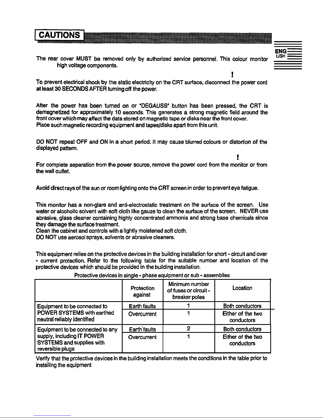
! CAUTION for 200V operation only
This
equipment relies on
the
protective devices in the building installation for short - circuit and
over
-
current protection. Refer to the following
table
for the suitable number and location of
the
protective devices which should be provided in the building installation.
Protective devices in single - phase equipment or
sub -
assemblies
4
Protection
against
Minimum number
of fuses or circuit
-
breaker poles
Location
Equipment to be connected
to
POWER
SYSTEMS with earthed
neutral reliably identified
Earth faults
1
Overcurrent
1
Both
conductors
Either of the two
conductors
Equipment to be connected to any
Earthfaults
2
Both
conductors
supply, including IT
POWER
Overcurrent
1
Either of the two
SYSTEMS and supplies with
conductors
reversible plugs
Verify that the protective devices in the building installation meets the conditions in
the
table prior to
installing the equipment
3
Page 6
EF;z
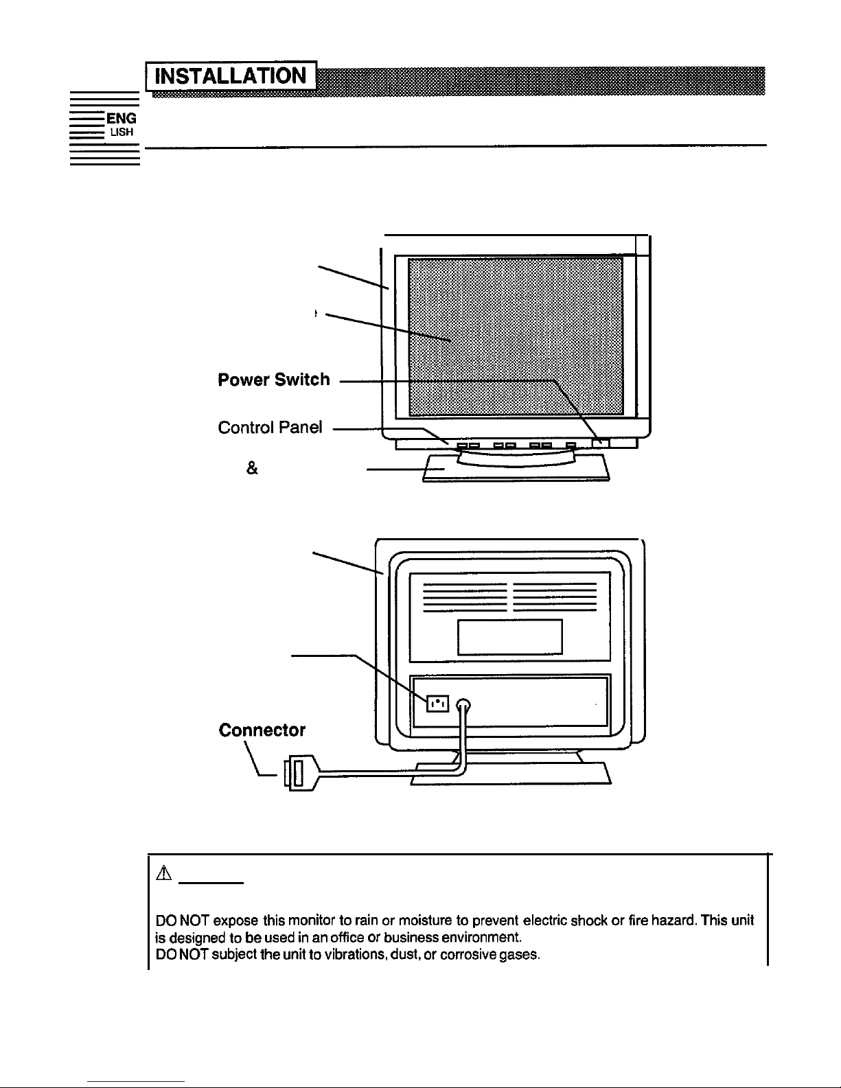
Install the monitor in the following way, taking care to maintain safety.
1. Installation
Install the monitor on a horizontal base.
Front Cover
CRT Surface
Tilt
& Swivel Base
I
FRONT VIEW
Rear Cover
AC Inlet
-I
Signal Input
CoYector
I
REAR VIEW
A
NOTICE
INSTALL THE UNIT IN ADEQUATE ENVIRONMENT !
DO NOT
expose this monitor to
rain
or moisture to prevent electric shock or
fire
hazard.
This
unit
is
designed to be
used in an office
or business environment.
DO NOT
subject the
unit to
vibrations,
dust,
or corrosive
gases.
4
Page 7

KEEP IN A WELL VENTILATED PLACE !
DO NOT
cover this monitor or place anything against any sides (not
only
top, right and left side but
also rear
and
bottom side) of
unit.
Ventilation holes are provided at
all
sides of the rear cover
to
prevent the temperature from
rising.
KEEP AWAY FROM HEATING RADIATION OR SOURCE !
AVOID placing the unit in direct sunshine or near a heating appliance.
BE CAREFUL OF MAGNETIC FIELDS !
DO NOT
place a magnet, loudspeaker system, floppy disk drive, printer, or anything which will
generate magnetism near the
unit. A
magnetic field
may
cause blurred colours or distortion of
the
displayed pattern.
2. Power Cord Connection
0
Make sure of using the power cord meeting the safety standard of the
country, you are using the monitor.
@
Insert the connector of a power cord to the
AC
Inlet of the monitor.
@I
Insert the plug of the power cord to a receptacle of the correct voltage.
/
%
AC Inlet
-yt
\’
--
--
1’
1
to
a receptacle of
the correct voltage
POW@’ Cord
,
a
a+=
/ 11
\
AQ
’
REARVIEW
B
NOTICE
q
In
USA/Canada, use a UL LlSTED/CSA
LABELLED or CERTIFIED
power
cord
set meeting
the
following specifications.
Rating: min. 125V,
7A
Length:
max.
3.1 m
Type:
SVT
or
SJT
Plug
type:
NEMA 5-15P,
Parallel blade, Grounding type,
125V, 15A
In
Europe, a proper European standard approved power
cord is
to be
used
with this monitor.
For
a rated current up to 6 A, a
type
not lighter than H05W-F 3G 0.75
mm2 or
H05WH2-F
3G
0.75
mm2
shall be
used.
Failure to do so may cause fire or electric shock hazard.
w The enclosed power
cord
shall be used if provided.
n
Use only
the correct
voltage
power outlet with safety ground connection.
100 - 120 V
for
USA,
Canada,
etc.
200 - 240 V for Europe, etc.
(This
monitor automatically adjust to the input voltage
100 - 120 /
200 -
240V.)
n The receptacle should be close to the monitor
and
easily accessible.
5
Page 8

A FOR THE CUSTOMERS IN U.K.
THIS PRODUCT IS SUPPLIED WITH
A
TWO PIN MAINS PLUG FOR USE IN
MAINLAND
=ENG
EUROPE. FOR
THE
U.K. PLEASE REFER TO THE NOTES ON THIS PAGE.
-
USH
IMPORTANT FOR UNITED KINGDOM
WORDING FOR CLASS I EQUIPMENT INSTRUCTION BOOKS AND LABELS
The mains lead on this equipment is supplied with a moulded
plug
incorporating a
fuse,
the
value
of which is indicated on the
pin
face of the
plug.
Should the fuse need to be replaced, an
ASTA
or
BSI
approved BS
1362
fuse must be
used
of the same rating.
If
the fuse cover is detachable never
use the
plug
with
the
cover omitted.
If
a replacement fuse cover
is
,xtuired,
ensure it is of the same
oolour as that visible on the
pin
face of the
plug.
Fuse
oovers are available from your dealer.
DO NOT
cut off the mains
plug from
this equipment.
If
the
plug
fitted is not suitable for the power
points in your home or the cable is
too shot-l to
reach a power point, then obtain an appropriate
safety approved extension lead or consult
your
dealer.
Should it be necessary to change the mains
plugs,
this must be carried out by a competent person,
preferably a qualified electrician.
If
there is no alternative to cutting
off
the mains
plug,
ensure that you dispose of it immediately,
having
first
removed the
fuse,
to avoid a possible shook hazard by inadvertent connection to the
mains supply.
WARNING: THIS EQUIPMENT MUST BE EARTHED
IMPORTANT
The wires in the mains lead are coloured in accordance with the following code:
Green and Yellow =
Earth, Blue = Neutral, Brown =
Live.
Green
&Yellow
to
Earth
Brown to Live
Fuse
Blue to
Neutral
Cord Clamp
As
these colours may
not
correspond
with the coloured
markings
identifying the terminals in
your
plug, proceed as
follows:
The wire which is coloured GREEN
and
YELLOW
must be connected to
the terminal in the
plug
which is
marked
with the letter E or
by
the earth
symbol @ or
coloured GREEN or GREEN
and
YELLOW.
The
wire coloured BLUE
must be
connected to the terminal marked with the letter N or
coloured BLUE or BLACK.
The
wire coloured BROWN
must be connected to
the terminal
marked
with the letter L or coloured BROWN or RED.
6
Page 9

3. Signal Input Connection
Connect the Signal Input Connector
to the D-Sub Mini
IBpin
signal output
terminal of the host computer.
to the
host computerb’Q I g
+@-
,
Signal Input
REAR
VIEW
Connector
ENGe
LISH -
l If the graphics board supplies more than one type of sync. signal, the sync.
signal type will be automatically selected by the monitor, with the priority
shown in the following table.
4. Power On
Turn
on
the
Power Switch of
the monitor first, then the computer.
Refer to Page 9 ‘POWER ON/OFF”.
NOTICE
w After turning OFF the switch, wait at least 5 seconds to restart the monitor.
Otherwise the monitor may operate unusually.
n
If
the picture doesn’t appear,
turn
OFF the power
switch,
make sure of’the following and
wait
at least 30 seconds to restart the monitor.
Make sure the power
switch
of the computer, power cord connection, signal cable connection
and the input
sync.
signal are
right.
1 If
the colour is impure on the screen after turning ON the monitor, wait for about 10 minutes
and press the Degauss button.
7
Page 10

l Microprocessor-based preset functions can store 20 sets of geometry
settings including the standard settings. Below listed preset modes.
The following industrial standard settings have been preprogrammed by the
factory.
NOTE
w Input
signals with approximately the same frequencies may be regarded as the same
signal.
n The following horizontal timing conditions are recommended.
Horizontal front
porch
should be more than
0.1 us.
Horizontal
sync. width
should be more than 1 .O
us.
Horizontal back
porch
should be more than
1.2 us.
Horizontal blanking width should be more than
3.0 ps
for 31
kHz - 55 kHz
or
2.7 ps for 55
kHz - 82 kHz
w
The following vertical timing conditions are recommended.
Vertical front
porch
should be more than
10.9 us.
Vertical
sync.
width
should
be
less
than
0.3 ms.
Vertical back
porch
should be more than 400
us.
Vertical blanking width should be more than 450
us.
q
In
case the front or
back porch is
extremely
long,
or the data display time is extremely
short, it
may
not be
able to set the expected size and position.
n
Standard settings are subject to change without
notice.
8
Page 11

-
Control Panel
p
-Function
LED
Power
LED
‘p--l~Jj
[-=-g-J
F&T-J
ffy
-O
@
F”t;;;N
+fOR~
I
ADJUST
DEGAUSS
Switches Switches Switch
I
..i
I
I
I
I
page 12
“STORE
Page s-t I
‘ADJUSTMENT
=
Page 9
Pagb9
‘DEGAUSSING
‘POWER
ON/OFF”
I
POWER ON/OFF
l
Press the POWER switch 0, to switch the power ON/OFF.
Dal
H
When
power is
ON, the
Power
LED
lights on green.
&2
DEGAUSSING
E!?!!?
a
Press the DEGAUSS switch, to degauss manually.
n
Use
this function
only
when you see colour impurities on the screen after turning ON the
monitor. Remember, the monitor is automatically degaussed during initial power on.
H
Wait for about 10 minutes before repeating the function.
ADJUSTMENT
(Contrast,
Brightness)
1 +.’ :‘?:“ ~-.-s’,
...~~~~~~:
l
You can adjust Contrast/Brightness by the ADJUST
:: >‘$$ ; ;,g&:.
,’ -~‘&~~&sTi._kI”:
/SELECT switches, as shown in the following table.
n
lng&n~z:.
( L. ri’i.i.8-I:’ ,
n
When
the Function
LED lights,
press the
FUNCTION switch
before the adjustment of Contrast/Brightness.
Sample of ‘EasyMenu”
n The On Screen Display function of “EasyMenu” shows adjusting item
and
condition.
n You can store the adjusted condition. Refer to Page 12 ‘STORE”.
Item
Adjust
Switch
Function
Contrast
makes Contrast brighter excluding background.
makes Contrast darker excluding background.
[:TF]
makes
Brightness
brighter including background.
Brightness
Q
fyy$]
makes
Brightness
darker including background.
au-
Page 12

ADJUSTMENT (others)
a
=aNG
l You can adjust the items shown in the following
._
-
USH
table, as
show;
below.
1. Press the FUNCTION switch. The Function
LED will light, and the EasyMenu will appear.
~~~
2. Select the item by the SELECT switches. The
selected item is indicated by magenta icon on
the
EasyMenu.
Qr-$o
3. Adjust the selected item by the ADJUST
h
switches.
n
You can store the adjusted condition.
Refer to Page 12 ‘STORE”.
.
Item
Selected Adjust
Icon
Switch
Function
moves the position to the right.
H. Position
moves the position to the left.
H. Size
expands horizontally.
shrinks
horizontally.
V. Position
moves the position up.
moves the position
down.
V. Size
expands vertically.
shrinks
vertically.
Signal
Status
Display
turns ON
the input signal information display function.
Refer to
Page 17
“SIGNAL
STATUS
turns
OFF the input signal information display function.
Pincushion
curves the left/right sides outwards.
curves the left/right sides
inwards.
70
Page 13

‘:.U”
for Colour Select is not available
before an adjustment is made by the
user.
There are no factory settings of
selects the previous
colour mode
‘.-.U”.
Refer
to
Page 17 ‘STORE”.
n
When
the selected colour
B’
reached to
its
maximum
or
makes the selected
colour weaker.
minimum
end and you
still
need to adjust the colour,
adjust the other two colours
to the other direction.
11
Page 14

STORE
-:;f
l Press the STORE switch, to store the currently adjusting data
fnllnwc
STORED
Item
H.Position
H.Size
V. Position
V.Size
Pincushion
Trapezoid
Storing Condition
Restoring
Condition
One setting is allowed
for
each video mode.
You
can
store maximum 20
sets
of geometry
the same video mode.
settings
including
the standard settings (refer
to page 8
“STANDARD SETTINGS”).
n
If
your store is at
its
maximum already,
storing a setting for new video mode
overwrites the oldest
user setting.
n
The video mode is distinguished by the
horizontal/vertical frequency
and
polarity
of the horizontal/vertical
sync. signal.
When
the
video
modes are almost similar
in
these
factors,
however, the video modes
may not be discriminated as
different.
Colour Balance
One
setting is allowed to the colour balance
When
the colour balance
(Red,
Green, Blue)
“.‘“.
“:.lJ” is selected.
Rotation
One setting is allowed.
When
the monitor
Contrast
One
setting is allowed.
detects a valid
signal.
Brightness
n
It is
normally not necessary to store
them
manually. No operation of about
15
Colour Select
seconds stores the currently adjusting data
Signal Status
of these
items,
automatically.
Display
RESET
l
Only when you want to cancel all your storing data,
turn ON the POWER switch 0 while pressing the
*
i-j--J
ADJUST switches together, to reset to the original
standard settings. All your storing data will be lost and the all adjustment
condition will be returned to the original settings.
q
If
you perform
this
function the reset will take approximately 5
seconds.
12
as follows
When the monitor detects
Page 15

SIGNAL STATUS
l
When the monitor has detected the change of the signal input condition, the
monitor will indicate the condition automatically, as follows.
Condition
I
Indication Sample of ‘EasyMenu”
I I
When
the monitor
detects proper signal.
The EasyMenu indicates the horizontal
frequency and vertical frequency.
1
Precision frequency,
Horizontal approximately it 1
kHz
Vertical approximately
*2Hz
N
Provided the Signal Status Display
function is set to
ON.
Refer to Page
10
‘Signal Status Display”.
When the monitor
The Function
LED blinks.
detects no sync-
signal,
N
Verity power switch of the computer
or
a
sync.
signal which
is
-
and cable connection.
out of set-up specifi-
cation or is unstable.
When the monitor
will
go The Power
LED lights on ORANGE.
into
the
power
saving
N
Verify power switch of the computer
mode.
-
and cable connection.
(Refer to page
19)
I I
VIDEO MUTING
l
When the monitor has detected the change of the signal input condition, the
monitor mutes the picture automatically.
This function hides scrambled images which may appear during the
changing period of the input signal.
The muting period depends on the time that takes until the replaced signal
becomes stable.
ENG-
LISH
-
-
13
Page 16

Et;f
l
This monitor complies with VESA, Nutek, and Energy Star power saving
requirements. The power saving system works only when used with VESA
DPMS compliant PC’s and/or graphic controllers.
e
This monitor complies with VESA
DDC1/2B
specifications.
Plug & Play is a system with computer, peripherals (including monitors), and
operating system.
It works when the monitor is connected to DDC ready computer that is
running an operating system software that is capable for the plug
&
play.
Page 17

CRT
17
inches picture tube, Anti-Reflection coat,
0.22 mm (optional 0.24
mm)
horizontal dot
pitch,
lnvar shadow mask, Black matrix, Short persistence
phosphors.
ENGS
USH
-
-
Input Signal
Video
Sync.
:
0.7 Vp-p, Analog
:
Separate H, V or Composite
H/V
lTL
level (optional Sync. on Green at 0.3 Vp-p)
Synchronization
Horizontal : 31 -‘82
kHz
Vertical
: 50-120Hz
Resolution
Horizontal : Up to 1,280 dots
Vertical
: Up to
1,024 dots
Video Clock Frequency
135 MHz
(max.)
Viewable
Image Size
Viewable
Image Area
Colour Temperature
Warm-up Time
Power Supply
Dimensions
Weight
Environmental
Condition
15.9
inches (404
mm),
diagonal
Horizontal : 325
mm
Vertical
:
245
mm
Standard Colour Balance
:.l :
9300
K
Standard Colour Balance
:.2 :
6500
K
Colour Balance :.U : User defined
30 minutes to reach optimum performance level.
AC 100 - 120 /
200 - 240 V, Automatically select.
Provided with Power Save
Circuit.
Power Consumption :
110 W
(nominal)
410
ON)
x 429
(H)
x 465
(D)
mm
Including Tilt & Swivel base.
22
kg
Operation
Storage
Temperature
:
10°C to
30°C
-20°C
to 60°C
Humidity
:
10% to 60%
10% to
90% *
*
Specification and Design are subject to change without notice.
15
 Loading...