

Page 1
HITACHI
COLOUR
MONITOR
CMl711ME
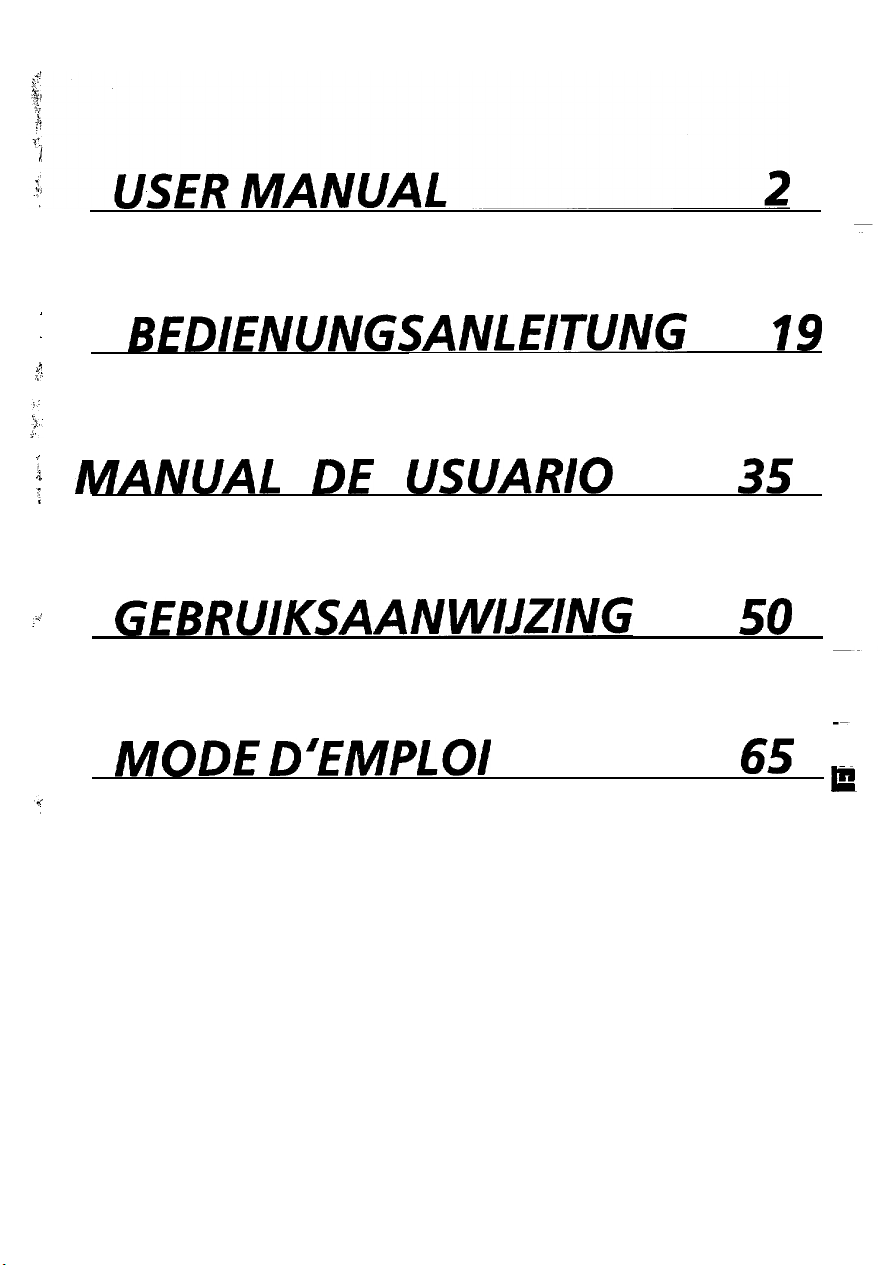
USER MANUAl
BEDIENUNGSANLNTUNG
MANUAL DE
GEBRUIKSAANWISZNG
MODE
USUARIO
D’EMPLOI
/
READ THE INSTRUCTION INSIDE CAREFULLY.
KEEP THIS USER’S MANUAL FOR FUTURE REFERENCES.
Forfuture references, record the serial number of your
Color monitor.
SERIAL No.
The serial number is located on the rear of the monitor.
:
EPA POLLUTION PREVENTER
This monitor is Energy Star compliant when
used with a computer equipped with VESA
DPMS.
The Energy Star emblem does not represent
EPA endorsement of any product or service.
Page 2

Page 3
:
.s
;:
BEDIENUNGSANLEITUNG
19
; MANUAL DE USUARIO
:.’
GEBRUIKSAANWIJZING
MODE D’EMPLOI
35
50
65
E
1
Page 4
i
NOTICE
The information in this manual is subject to change without notice. Hitachi assumes no
1
-
responsibility for any errors that may appear in this manual.
E
TRADEMARK ACKNOWLEDGMENT
VGA is a registered trademark of international Business Machines Corporation.
Apple and Macintosh II are registered trademarks of Apple Computer, Inc..
VESA is a trademark of a nonprofit organization, Video Electronics Standard Association.
Energy Star is a trademark of Environmental Protection Agency.
2
Page 5
FEATURES
CAUTIONS
INSTALLATION
STANDARD SETTINGS
OPERATION
POWER SAVING SYSTEM
VESA DDC
SPECIFICATIONS
The following features are provided by the HITACHI Colour Monitor.
........................................................
........................................................
....................................................
.............................................
.....................................................
..........................................
.......................................................
..................................................
3
4
6
10
11
17
17
18
Sharpest Focus and Highest Contrast
Flat screen CRT with anti-glare, dynamic focus circuit, dark glass, and an INVAR shadow
gives the sharpest focus and highest contrast to minimize eye fatigue.
mask
Wide-range Multi-Scanning
Automatic scanning and automatic adjustment to conform with a wide range of scanning
frequencies and user requirements.
Digital Picture Control Function
Size, position, trapezoid, rotation and side pincushion are adjustable by digital controls.
Geometry setting can be stored for different H/V frequencies. Microprocessor-based preset
functions can store 20 sets of geometry settings including the standard factory settings.
Digital Colour Control Function
Red, green, and blue colour balance is adjustable by digital control.
Adjusted colour setting can be stored and recalled by the colour select.
Power Saving System
The Environmental Protection Agency has established a voluntary program by which
manufacturers enable computer products to go into low power states while not being used.
This monitor has a low power “sleep” mode, which is compliant with the EPA requirements for
the “Energy Star” program, and will assist you in conserving energy.
Please refer to the section “POWER SAVING SYSTEM” for details.
EasyMenu
On Screen display function that enables direct access to adjust operations from front panel.
VESA DDC (Display Data Channel)
This monitor is VESA DDCl/ZB compliant when used with a computer compliant with VESA
DDC.
3
Page 6
I
A
NEVER REMOVE THE REAR COVER !
-mj
The rear cover MUST be removed only by authorized service personnel. This
contains high voltage components.
’
A
BE CAREFUL OF STATIC ELECTRICITY ON CRT SURFACE !
To prevent electrical shock by the static electricity on the CRT surface, disconnect the power
cord at least 30 SECONDS AFTER turning off the power.
Le,
BE CAREFUL OF GENERATED MAGNETISM !
After the power has been turned on or
demagnetized for approximately 10 seconds. This generates a strong magnetic field around the
front cover which may affect the data stored on magnetic tape or disks near the front cover.
Place such magnetic recording equipment and tapes/disks apart from this unit,
m
AVOID FREQUENT POWER ON-OFF SWITCHING !
DO NOT repeat OFF and ON in a short period. It may cause blurred
displayed pattern.
“DEGAUSS”
button has been pressed, the CRT is
colours
colour
monitor
or distortion of the
fb REMOVE THE POWER CORD FOR COMPLETE SEPARATION !
For complete separation from the power source, remove the power cord from the monitor or
from the wall outlet.
m AMBIENT ILLUMINATION
Avoid direct rays of the sun or room lighting onto the CRT screen in order to prevent eye
fatigue.
m
ABOUT CLEANING
This monitor has a non-glare and anti-electrostatic treatment on the surface of the screen.
water or alcoholic solvent with a soft cloth like gauze to clean the surface of the screen.
NEVER use abrasive, glass cleaner containing highly concentrated ammonia and strong base
chemicals since they damage the surface treatment.
Clean the cabinet and controls with a lightly moistened soft cloth.
DO NOT use aerosol sprays, solvents or abrasive cleaners.
Use
m
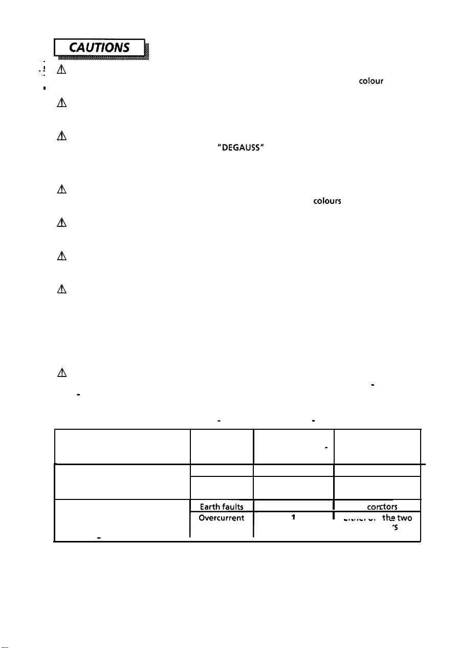
CAUTION for 200V operation only
This equipment relies on the protective devices in the building installation for short - circuit and
over - current protection. Refer to the following table for the suitable number and location of
the protectivedevices which should be provided in the building installation.
Protective devices in single - phase equipment or sub - assemblies
Protection
against of fuses or circuit
I
Equipment to be connected to Earth faults
POWER SYSTEMS with earthed
neutral reliably identified
Equipment to be connected to
any supply, including IT POWER
SYSTEMS and supplies with
reversible plugs
I
Verify that the protective devices in the building installation meets the conditions in the table
prior to installing the equipment.
-
Overcurrent
I
Minimum number
breaker poles
1
1
2
1
I
-
Location
Both conductors
Either of the two
conductors
1
Both
I
Fithnrnf
-....-. -.
conductor
I
I
conduc
tars
thetwo
.
..-
‘5
_
I
Page 7

m
FCC STATEMENT
The following statement applies to this product.
Federal Communication Commission (FCC) Statement Warning:
NOTE:
This equipment has been tested and found to comply with the limit for a Class B digital
device, pursuant to part 15 of the FCC Rules. These limits are designed to provide reasonable
protection against harmful interference in a residential installation. This equipment
generates, uses, and can radiate radio frequency energy and, if not installed and used in
accordance with the instruction, may cause harmful interference to radio communications.
However,there is no guarantee that interference will not occur in a particular installation. If
this equipment does cause harmful interference to radio or television reception, which can be
determined by turning the equipment off and on, the user is encouraged to try to correct the
interference by one or more of the following measures.
-Reorient or relocate the receiving antenna.
-
Increase the separation between the equipment and receiver.
-Connect the equipment into an outlet on a circuit different from that to which the
receiver is connected.
-Consult the dealer or an experienced radio/TVtechnician for help.
CAUTION:
Changes or modifications not expressly approved by the party responsible for compliance
could void the user’s authority to operate the equipment.
h
FOR THE CUSTOMERS IN CANADA
NOTICE: This digital apparatus does not exceed the class B limits for radio noise emission for a
digital apparatus as set out in the radio interference regulations of the Canadian department
of communications.
m
POUR LES
UTILISATEURS
AU CANADA
AVIS: CET
BRUITS
DANS LE
COMMUNICATIONS CANADIENNE.
APPAREIL NUMERIQUE
RADIOELECTRIQUES
RtGLEMENT
SUR LE
N’EXCEDE PAS LES
PROVENANT DES
BROUILLAGE RADIOELECTRIQUE EMIS
LIMITES
APPAREILS NUMERIQUES
DE LA CLASSE
TEL QUE STIPULE
PAR LE
MINISTERE
,‘B”
SURLES
ERGONOMICS
Under the requirements of
1.
Blue graphics or characters in dark background are not recommended. (This
may increase eye fatigue due to poor visibility caused by low contrast.)
Graphics controller and monitor are recommended to be used in the following conditions :
2.
. Display mode
s
Vertical frequency :
german
ergonomics standard ZH 11618, draphics or characters.
: Dark characters in bright background.
70H.z
or higher.
conbination
DES
5
Page 8

Install the monitor in the following way, taking care to maintain safety.
!
1. Installation
Install the monitor on a horizontal base.
Front Cover
Control Panel
Rear Cover
-
ll”PT~llml-I
’
-5
, CRT Surface
Y
Power Switch
Tilt & Swivel Base
FRONT VIEW
/
-
REAR VIEW
6
Page 9

m
INSTALL THE UNIT IN AN ADEQUATE ENVIRONMENT !
DO NOT expose this monitor to rain or moisture to prevent electric shock or fire hazard.
This unit is designed to be used in an office or business environment.
DO NOT subject the unit to vibrations, dust, or corrosive gases.
m
KEEP IN A WELL VENTILATED PLACE !
DO NOT cover this monitor or place anything against any sides (not only top, right and left
side but also rear and bottom side) of unit. Ventilation holes are provided at all sides of the
rear cover to prevent the temperature from rising.
A
KEEP AWAY FROM HEATING RADIATION OR SOURCE !
AVOID placing the unit in direct sunshine or near a heating appliance.
A
BE CAREFUL OF MAGNETIC FIELDS !
DO NOT place a magnet, loudspeaker system, floppy disk drive, printer, or anything which
will generate magnetism near the unit.
distortion of the displayed pattern.
A magnetic field may cause blurred
colours
2. Power Cord Connection
0
Make sure the Power Switch is “OFF”.
Q Make sure to use a power cord meeting the safety standard of the
country, in which you are using the monitor.
0
Connect a power cord to the “AC Inlet” of the monitor.
@
Connect the plug of the power cord to a receptacle of the correct
voltage.
or
A
In USA/Canada, use a UL LISTEDKSA
following specifications.
Rating: min.
Plug type: NEMA
Failure to do so may cause fire or electric shock hazard.
In Europe, a proper European standard approved power cord is to be used with this
monitor. For a rated current up to 6 A, a type not lighter than
HOSWHZ-F 3G 0.75
A
The enclosed power cord shall be used if provided.
A
Use only the correct voltage power outlet with safety ground connection.
100 - 120 V for USA, Canada, etc.
200 - 240 V for Europe, etc.
(This monitor automatically
A
The receptacle should be close to the monitor and easily accessible.
125V,
7A
5-15P,
Parallel blade, Grounding type,
mm2
shall be used.
adjust to
LABELLED
Length: max. 3.1 m
the input voltage 100 -
or CERTIFIED power cord set meeting the
Type: SVT or SJT
125V,
15A
HOSW-F 36
120/
200 - 240V.)
0.75
mm2
or
7
Page 10

I
A
FOR THE CUSTOMERS IN U.K.
:
THIS PRODUCT IS SUPPLIED WITH A TWO PIN MAINS PLUG FOR USE IN MAINLAND EUROPE.
--!
FOR THE U.K. PLEASE REFER TO THE NOTES ON THIS PAGE.
I
WORDING FOR CLASS I EQUIPMENT INSTRUCTION BOOKS AND
The mains lead on this equipment is supplied with a
value of which is indicated on the pin face of the plug. Should the fuse need to be replaced, an
ASTA or
detachable never use the plug with the cover omitted. If a replacement fuse cover is required,
ensure it is of the same
available from your dealer.
DO NOT cut off the mains plug from this equipment. If the plug fitted is not suitable for the
power points in your home or the cable is too short to reach a power point, then obtain an
appropriate safety approved extension lead or consult your dealer.
Should it be necessary to change the mains plugs, this must be carried out by a competent
person, preferably a qualified electrician.
If there is no alternative to cutting off the mains plug, ensure that you dispose of it
immediately, having first removed the fuse, to avoid a possible shock hazard by inadvertent
connection to the mains supply.
BSI
approved BS 1362 fuse must be used of the same rating. If the fuse cover is
IMPORTANT FOR UNITED KINGDOM
LABELS
moulded
colour
as that visible on the pin face of the plug. Fuse covers are
plug incorporating a fuse, the
WARNING: THIS EQUIPMENT MUST BE EARTHED
IMPORTANT
The wires in the mains lead are coloured in accordance with the following code:
Green and Yellow = Earth, Blue = Neutral, Brown = Live.
Green &Yellow
to Earth
Blue to Neutral
As these
your plug, proceed as follows:
The wire which is coloured GREEN and YELLOW must be connected to the terminal in the plug
which is marked with the letter E or by the earth symbol @ or coloured GREEN or GREEN and
YELLOW.
The wire coloured BLUE must be connected to the terminal marked with the letter N or
coloured BLUE or BLACK. The wire coloured BROWN must be connected to the terminal marked
with the letter L or coloured BROWN or RED.
colours
may not correspond with the coloured markings identifying the terminals in
Brown to Live
Fuse
Cord Clamp
Page 11

3. Signal Cable Connection
l
use a signal cable with the
D-Sub Mini 15-pin Connector.
Cl Insert connector to the “video signal Terminal” (D-Sub Mini 15-pin Connector
Terminal) at the rear of system, and secure the screws on the connector shell firmly.
l
If the graphics board supplies more than one type of sync. signal, the
sync. signal type will be automatically selected by the monitor, with
the priority shown in TABLE 2.
TABLE 2
Sync. Signal Type
H., V. Separate Sync.
H IV Composite Sync.
Sync. on Green Video (optional)
Priority
1
2
3
9
Page 12

I 4.
Power
On
Turn on the Power Switch of the monitor first, then the computer.
NOTICE:
1.
After turning OFF the switch, wait at least 5 seconds to restart the monitor.
Otherwise the monitor may operate unusually.
2.
If the picture doesn’t appear, turn OFF the power switch, make sure of the following
and wait at least 30 seconds to restart the monitor.
Make sure the power switch of the computer, power cord connection, signal
cable connection and the input sync. signal are right.
3. If the colour is impure on the screen after turning ON the monitor, wait for about
minutes and press the Degauss button.
an
standard settings. 7 sets are preset at factory, 13 sets are available to users.
store a number of geometry settings including the
rammed by the factory.
JJ
10
NOTE:
1. Input signals with approximately the same frequencies may be regarded as the
samesignal.
2. The following horizontal timing conditions are recommended.
Horizontal front porch should be more than
Horizontal sync. width should be more than 1
Horizontal back porch should be more than
Horizontal blanking width should be more than
3.0~s (for45kHz -
3.
The following vertical timing conditions are recommended.
Vertical front porch should be more than
Vertical sync. width should be less than 0.3ms.
Vertical back porch should be more than
Vertical blanking width should be more than
4. If either the front or back porch is extremely long, or the data display time is
extremely short, it may not be able to set the expected size and position.
5.
Standard settings are subject to change without notice.
82kHz
1.
0.1~~.
.Ous.
1.2us.
12.2~5.
4OOus.
45Ous.
3.5us
(for 24.8kHz - 45kHz ) or
Page 13

Control Panel
b
~“l--Qrc,eYysy(
\
/
I
/I
f!
I
I
4
Power Switch
.
:Gi
. . . . . . . . . . . . . . . . . . . . . . . . . . . . . . . . . . . . . . . . . . . . . . . . . . . . . . . . . . . . . . . . . . . . . . . . . . . . . . . . . . . . . . . . . . . . . . . . . . . . . . . . . . .
I
FUNCTION
(EasyMenu )
•I If two or more buttons are pressed at the same time, they will be invalid except when
mentioned in the following cases.
POWER ON/OFF
DEGAUSSiNG
DEGAUSS
ADJUSTMENT 1 (Contrast, Brightness)
Contrast [ @ ]
I
52
STORE
+
I I
I
l
Press the switch [ 0
to switch the power ON/OFF.
When power is ON, the power LED will light on green.
l
Press the button
Use this button only when you see
screen after turning ON the monitor. Remember, the monitor
is automatically degaussed during initial power on.
Cl
Wait for about 10 minutes before repeating this function.
Press the button [ 0 - ] OR [ @ +
0
Contrast adjustment condition
appears on the screen.
I
ADJUSTMENT
1,
[
DEGAUSS
4F
],
=
DEGAUSS
I
DEGAUSSING
to degauss manually.
colour
impurities on the
]
DD
I
Q
[
@ + ] makes the display brighter,
IQ- 1
excluding the background.
makes the display darker, excluding
the background.
11
Page 14

I!
Brightness [ 0 ]
Press the button [ -0 - ] OR [ -0 +
0
Brightness adjustment condition
appears on the screen.
[
a:@
+ ] makes the display brighter, including
the background.
[ .a -]
makes the display darker, including
the background.
ADJUSTMENT 2 (Others)
0
Adjust the following items after selecting the function as shown below:
0
FUNCTION
m @x+x g3 $) f@)
y? !‘“”
-.a a”“.
.&gJ
9
I
0% &%
::
llllllllllllllllllllll~og~~~~~~
_._._._._._._._._._.-.-.-.-.-.-.-.-.-.-.-.-.-.-.-.-.-.-.-.-.-.-.-.-.-.-.-.-.-.-.-
Horizontal
0 gT.IT.I$ f.?.? (yJ (gg
*y”J c3&
POSitiOrl
$3. o”u g&J
111111111111ll111111ll~=~~~~~~~=
,..........................................,..............................................................................
Horizontal Size
\(“yJj g &zJ f$) $jijJ
Kf C-J f3. go &y$j
llllllllllllllllllllll==-~-~
,..................................,.,...................,,.....................,.........................................
Vetiid POSitiOn
Q%$ $gg (g ff) @g
$-J EJ -@ go &f-y&
llllllllllllllllllllllmm=---
72
Press the button 1 FUNCTION
(EasyMenu)
0
FUNCTION
adjustment conditions appear
EasyMenu on the screen.
@
Press the button [ SELECT - ] or
f[,‘~~~~
0
The selected function icon colourturns
cyan to magenta.
@I
Press the buttun [ ADJUST - ] or
[ADJUST +].
0
Adjust the selected function.
@Select
select buttons.
0
The function icon [a ] colour turns cyan to magenta.
@Press the button [ ADJUST - ] or [ ADJUST
[ADJUST + ] moves the display position to the right.
[ADJUST -]
@Select
select buttons.
q
The function icon [ 8 ] colour turns cyan to magenta.
0
Press the button [ ADJUST - ] or [ ADJUST
[ADJUST + ] expands the image horizontally.
[ADJUST - ] shrinks the image horizontally.
0
Select the icon
select buttons.
Cl
The function icon [a ] colour turns cyan to magenta.
Q
Press the button [ ADJUST - ] or [ADJUST
[ ADJUST + ] moves the display position up.
[ ADJUST -]
.
(EasyMenu)
LED is lit, and
ifolnand
the icon
the icon
se’ect
the
[a ]
on the
moves the display position to the left.
[ l3 ]
on the
[@I ]
on the
moves the display position down.
]
]
_ tag
-*
EasyMenu
EasyMenu
EasyMenu
H
F!L
v-
32
??!?
!-I
by using
+I.
by using
+I.
by using
+I.
N
+
+
Page 15

I.........................................~...............................................................................
Vertical Size
0
@I
. . . . . . . . . . . . . . . . . . . . . . . . . . . . . . . . . . . . . . . . . . . . . . . . . . . . . . . . . . . . . .
Status Select
@ ;~kt~~~~icc~ [ Q I
Q
Select the icon
[
CD ]
on the
EasyMenu
by using
select buttons.
El
The function icon [a ] colour turns cyan to magenta.
Press the button [ ADJUST - ] or [ ADJUST +].
[ADJUST + ] expands the image vertically.
]
[
ADJUST
0
The function icon [ @ ] colour turns cyan to magenta.
shrinks the image vertically.
-
on the
EasyMenu
*
. . . . . . . . . . . . . . . . . . . . .
by using
Press the button [ADJUST - ] or [ADJUST
[ADJUST + ] The input signal information is displayed
0
[ ON ] colour turns cyan to magenta.
[ADJUST
El
[ OFF] colour turns cyan to magenta.
Please refer to “STATUS”.
q
“ON mode”.
]
The input signal information is displayed
-
“OFF mode”.
-
+I.
Pincushion
0 S$~;~tiicc; [ I7 ]
on the
EasyMenu
by using.
~,~~~~~~, CJ.. ~~~~~
0
The function icon [n ] colour turns cyan to magenta.
‘,‘:I
&jjj$>
~~.“g&&&
$.C^{,&~ I,
~~~~~lllullll~llll~~~~~~~~
~&&j,.-&
‘I
‘.d ‘j, I? !
. . . . . . . . . . . . . . . . . . . . . . . . . . . . . . . . . . . . . . . . . . . . . . . . . . . . . . . . . . . . . . . . . . . . . . . . . . . . . . . . . . . . . . . . . . . . . . . . . . . . . . . . . . . . . . . . . . . . . . . .
*& e? <*
Trapezoid
,...,..................,................................................,.................................................
Rotation
@Press the button [ ADJUST - ] or [ ADJUST
[ ADJUST + ] curves both sides of the display outwards.
]
[ ADJUST
.’ -“-
@;Sek;;etiicc; [ 0 ]
I7 The function icon [a ] colour turns cyan to magenta.
Q
Press the button [ ADJUST - ] or [ ADJUST
[ADJUST + ] expands the top half and shrinks the bottom
[ADJUST
@I kkz ,$eiG;-~ [ 8 ]
0
The function icon [e ] colour turns cyan to magenta.
Q
Press the button [ ADJUST - ] or [ADJUST
[ ADJUST + ] rotates the whole image clockwise.
[ADJUST
curves both sides of the display inwards.
-
on the
half.
]
shrinks the top half and expands the bottom
-
half.
on the
]
rotates the whole image counterclockwise.
-
EasyMenu
EasyMenu
+I.
by using
+I.
by using
+I.
..
13
Page 16

. . . . . . . . . . . .
‘i%lour
0
Select the suitable colour balance / colour temperature.
_
You have a choice of two standard colour balance settings [
[
Cl [
:.2 ]
~_
. . . . . . . . . . . . . . . . . . . . . . . . . . . . . . . . . . . . . . . . . . . . . . . . . . . . . . . . . . . . . . . . . . . . . . . . . . . . . . . . . . . . . . . . . . . . . . . . . . . . . .
Select
:.l ]
(6500K), and one for your own colour balance setting [
:.U
]
please refer to ‘COLOUR ADJUSTMENT” and “STORE”.
@;%k&icc:
0
The function icon [ :. I colour turns cyan to magenta.
Q
Press the button [ ADJUST - 1 or [ADJUST
[ADJUST + ] changes the colour balance from [
[ADJUST
0
The
selectdd
magenta.
0[ :.U ]
0
is not available before an adjustment is made by the
user. There are no factory settings of [
If the adjustment is not “Stored’, the previous colour
setting appears next time.
[ :. ] on
then to I :.U I .
] Changes
-
then to [
colour balance icon colour turns cyan to
the
EasyMenu
the colour balance from [ :.U ] to [ :.2
.=l 1.
.
:.U 1.
.=U 1.
(9300K),
by using
,.........................................................................................................................
O;kk~r~~~icc;
Cl The function icon [ & ] colour turns cyan to magenta.
Q
Press the button [ ADJUST
0 [
ON ] colour turns from cyan to magenta, then Colour
Adjustment Menu appears on screen.
[ A 1
on the
EasyMenu
+I.
by using
@Press the button [ SELECT - ] or [ SELECT +] and
select the colour which you wish to adjust from
Red / Green / Blue.
[SELECT + I changes the colour selection from 1 R 1 to I G
[SELECT
q The selected colour
turns to the colour to be adjusted:
[RI
thento
[B].
]
changes the colour selection from [ B ] to [ G
-
then to
+Red,[G] -+Green,[Bl +Blue.
[RI.
[ R ] I [
G ] I [ B 1, +-, adjusting bar,
@Press the button [ ADJUST - 1 or [ ADJUST +
I
ADJUST + 1 Makes the selected colour stronger.
I
ADJUST
q Adjustment only affect the selected colour. However,
what you get on the screen is a mixture of three primary
colours. Therefore, when the selected colour reached to
its maximum or minimum end and you still need to adjust
the colour, select the other two colours and adjust to the
other direction.
I Makes the selected colour weaker.
-
@St.tgR;Fe adjusted data by pressing the button
+I.
:.l
I to [ :.2
]
]
1,
1,
I
14
Page 17

AUTOMATIC STORE
0
When the Function (EasyMenu) / Control buttons are not used for more
than 15 seconds, the current value of Brightness, Contrast and Colour
Select are automatically stored.
0
The previous data of Brightness, Contrast and Colour Select are overwritten when the
current value is stored.
Cl
If you press [Store] button, the current value is stored immediately. The current value is
not stored if you power off before 15 seconds passed.
STORE
l Store the adjusted data by pressing the button [STORE I.
OfOu”nl~rx;i~,;ted
Rotation,
Colouk
Colour balance is stored in the [ :.U
value can be stored for the
(Red, Green and Blue)
1.
Contrast, Brightness, Colour Select
These are usually stored automatically. Refer
to “AUTOMATIC STORE”.
Cl When a new value is stored, the previous data is
overwritten.
@One adjusted value for each video mode can be stored for the functions
below.
Horizontal Position
Horizontal Size, Vertical Position, Vertical Size,
Pincushion, Trapezoid,
El
The latest setting is restored to the image automatically when the same video mode is
used. Refer to “AUTOMATIC SETTINGS”
0
When a new value is stored in one video mode, the previous data in the video mode is
overwritten.
q The geometry for each standard video mode has been preset. (refer to ‘STANDARD
SETTINGS”) The user settings are available for up to 13 video modes.
q The video mode is detected by the horizontal
horizontal / vertical sync. signal. If two video modes are similar, much, there is a
possibility that they will not be identified as different.
0
Storing a setting for a 14th video overwrites the oldest one.
aTurn
~~%LATA CLEAR)
ON the power switch while pressing the
button
[
ADJUST +
/
vertical frequency and polarity of the
1
and
[
ADJUST
- 1
together,
to reset to the original standard settings.
(at the power QlJ only)
Use this function only when you want to cancel all your
e
I I
. All your storing data will be lost and the all adjustment
9
N~~~~Bl
.
.
If you perform this function the reset will take approximately
10 seconds.
be original.
15
Page 18

! STATUS
,0 The signal
the status select is set to “ON”.
When :
I
(1) The monitor is switched on. (Power ON)
(2) The signal timing changes.
” ;: ;!. ;kg
2
‘.
timing
.
status will be displayed on screen for 5 seconds provided
0
When the signal is valid, the status displayed on
screen is horizontal I vertical frequency.
When the signal is one of the standard preset,
the resolution will be displayed as well as
7:
horizontal / vertical frequencies.
( Standard presets are shown in “STANDARD
SETTINGS”)
The horizontal frequency indicated is accurate to
within 1
accurate to within 2 Hz.
@When
sync. signal which is out of set-up specification or
is unstable, the Function
blink.
Cl Please check the signal cable connection and the host
kHz.
The vertical frequency indicated is
the monitor detects no sync. signal or a
(EasyMenu)
computer.
LED will
VIDEO MUTING
0
When the monitor has detected a change within the signal input
condition, the monitor mutes the picture automatically.
This function hides scrambled images which may appear whilst the input
signal is changing.
The muting period depends on the time that is taken for the new signal
becomes stable.
AUTOMATIC
0
When the monitor receives a valid input signal, the picture is
automatically adjusted as follows.
@ Horizontal Position, Horizontal Size, Vertical Position, Vertical Size,
Pincushion,
Trapezoid (of each video mode)
@
Rotation, Contrast, Brightness, Colour Select (the latest setting)
16
SElTlNG
Page 19

signal condition, the POWER SAVING
SYSTEM will operate, and the ‘monitor will go into power saving mode
automatically.
In the power saving mode :
Power consumption is less than BW (approx. 5W).
The power LED lights on orange.
The monitor will recover when the right sync. signal is received.
“This monitor is Energy Star Compliant when used with a computer
equipped with VESA DPMS.”
Thefollowing power saving functions are provided by the HITACHI Colour Monitor.
1. Built-in Automatic Power Saving
An Automatic Power Saving function operates when no horizontal or vertical sync.
signal is supplied to the monitor.
2.
The monitor will conform to Display Power Management Signaling proposed by
VESA.
0
This monitor is VESA DDCllZB compliant when used with a computer
compliant with VESA DDC (Display Data Channel).
17
Page 20

I
y
CRT
17 inches diagonal,
lnvar shadow mask, Black matrix, Short persistence phosphors.
: Anti - Reflection coat,
0.26 mm (horizontal : 0.22 mm) dot pitch
(optional 0.28 mm (horizontal 0.24 mm))
Input Signal
Synchronization
Resolution
Video Clock
Frequency
;;&e
Display
Colour Temperature
Power Supply
Dimensions
Weight
Environmental
Condition
Video
Sync.
Horizontal
Vertical
Horizontal
Vertical
135 MHz
Horizontal
Vertical
The active display area is changed according to the graphics
board.
Standard Colour Balance 1
Standard Colour Balance 2
Colour Balance U : User defined
AC 100-1201200-240 V, Automatically select.
Provided with Power Save Circuit.
410
(W)
x 429 (HI x 465(D) mm
Including Tilt &Swivel base.
Temperature
Humidity
: 0.7 Vp-p, Analog
: Separate H, V or Composite H/V
TTL
level (optional Sync on Green at 0.3Vp-p)
: 24.8 - 82kHz
:
50-120Hz
: Up to 1,280 dots
: Up to 1,024 lines
(max)
: 305mm
: 230mm
: 9300K
: 6500K
: 22 kg
Operation
:
1O’C
to 30°C -20°C to 60°C
: 10% to 80%
10% to 90%
Storage
18
Specification and Design are subject to change without notice.
 Loading...