

Page 1
COLOUR MONITOR
141vlvxPliA
FARBMONITOR
MONITOR EN COLOR
MONITOR A COLORI
MONIIEUR COULEUR
CM1484ME
USER MANUAL
BEDIENUNGSANLEITUNG . . . . . . . . . . . . . . . . seite
MANUAL DEL USUARIO
INSTRUZIONI PER L’USO . . . . . . . . . . . . . . . . . . pag
MANUEL DE L’UTILISATEUR . . . . . . . . . . . . . .
. . . . . . . . . . . . . . . . . . . . . . . . . .
.= . . . . . . . . . . ..m. pAgina
page
page
2
10
18
24
30
Page 2
. NOTICE
The information in this document is subject to change without notice.
Hitachi assumea no responsibility for any errors that may appear in this document.
I
Colour Monitor 14MVX Plus
Operating Guide
Features:
The following features are provided with the HITACHI colour
Monitor 14MVXPhS:
Wide compatibility range of graphics standard, VGA, XGA,
8514/A, Super VGA, and Macintosh lIVideo Card.
Sharp focus and remarkable display quality by new design CRT.
Cubic and Simple design cabinet with Tilt and Swivel base.
LMF and LEF
This version of 14MVX Plus is built to meet Swedish requirements
for Low Magnetic Field and Low Electrostatics Field. Both features
are to reduce the suspected effects of magnetic field and Electrostat ics field to your health down to the MPR 11 recommendation level.
TRADEMASX ACXNOW-MENT
❑M PC PW’T, fIC/AT. ibciul Syti XGA. WA. d 85141A = r+lf=.d indurmb
Appieud~
hhdntd If VI&o Cmlisa trwk nmkof @le Canpufu, h=..
2 14MVX Plus User Manual
are mgistucd wdunuks d the APF4CComputer, be..
of Irdcmwiod Buimaa Mdtims Cmpmaum.
Page 3
For U.K. Customers
THIS PRODUCT IS SUPPLIED WITH A TWO PIN
MAINS PLUG FOR USE IN MAINLAND EUROPE. FOR
THE U.K. PLEASE REFER TO THE NOTES ON THIS
PAGE.
NOTE:
ELECTRICAL CONNECTION
Your monitor requires an electrical supply of 240 volts – 50 Hertz and
shfkld be protected by a 5 amp fuse. Your equipment is supplied with a
plug incorporating a 5 amp fuse fitted to the mains lead. If the plug that
is fitted to the equipment is not suitable for your socket outlet, it must be
cut off and the appropriate plug fitted. The cut off plug should be disposed
of, do not insert it into a 13 amp socket to prevent the hazard of electric
shocks. With pIugs not incorporating a fuse, the circuit must be protected
by a 5 amp fuse.
WARNING: THIS EQUIPMENT MUST BE EARTHED.
IMPORTANT
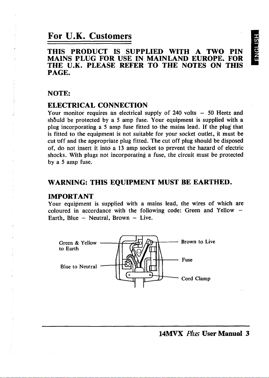
Your equipment is supplied with a mains lead, the wires of which are
coloured in accordance with the following code: Green and Yellow -
Earth, Blue – Neutral, Brown - Live.
Green & Yellow
to Earth
Blue to Neutral
1 1 \
f
Brown to Live
Fuse
Cord Clamp
14MVX Plus User Manual 3
Page 4

As the colours of the wires in your mains Iead in this equipment may not
correspond with the markings identified with the terminals of your plug,
proceed as follows:
The wire which is coloured Green and Yellow must be connected to the
terminal in the plug which is marked with the letter E or by the symbol
or coloured Green or Green and Yellow.
The wire which is coloured Brown must be connected to the terminal
which is marked with the letter L or coloured Red.
The wire which is coloured Blue must be connected to the terminal which
is marked N or coloured Black.
The plug moulded on to the cord incorporates a fuse. For replacement,
use a 3 amp BS1 362 fuse. Only ASTA approved fuses should be used.
The fuse cover/carrier must be refitted when changing the fuse. In the
event of losing the fuse cover/carrier, the plug must not be used until a
replacement has been obtained from your nearest electrical stockist and
fitted. The colour of the fuse cover/carrier is that of the coloured marks
on the insert in the base of the plug.
4 14MVX PZU.SUser Manual
Page 5

@EIi@
NEVER REMOVE THE BACK COVER
Removal of the back cover MUST be carried out only by
quaMed personnel. This display monitor contains high voltages
tilde.
DO NOT USE IN HOSTILE ENVIRONMENTS
DO NOT expose this d~lay monitor to rain or moisture to
prevent electric shock or fwe hazard. This unit is designed to be
used in the ofiice or home environment.
DO NOT subject the unit to vibrations, dust, or corrosive gases.
KEEP IN A WELL VENTILATED PLACE
DO NOT cover this monitor or place anything against the sides.
Ventilation holes are provided on the cabinet to prevent
the temperature from risiig. Ventilation holes are also provided
on the bottom and the top of the cabinet.
AVOID HEAT
Ill
Avoid placing the unit in direct sunshine or near a heating
appliance.
BE CAREFUL OF MAGNETIC
DO NOT place a magnet, loud speaker system, floppy d~k
drive, or anything which will genemte magnetism near the unit.
A magnetic field may cause blurred colors or distortion of the
displayed pattern.
FIELDS
14MVX PhASUser Manual ~5
Page 6

@PERATmG>
Controls
Front View
Rear View
m.
(7) (6) (5) (4) (3) (2) (1)
(1) Power Switch
Use this switch to power ON or OFF by pressing it.
When the power is ON, green light on the knob turns on to indicate.
(2) Contrast Control ((D)
Use this to set the foreground brightness cf the screen.
(3) Brightness Control (-,, ]
Use this to set the background to black.
Most of the latest application software utilizes coloured background and this control
is usually set at its maximum.
J)
(8)
(4) Horizontal Size (~]
Adjust this control to the preferred horizontal width. If the width is too wide, part of
information will be missed from the screen.
(5) Horizontal Position (~)
Adjust this to place the display at the centre of the screen.
6 14MVX F’hx.sUser Manual
Page 7

(6) Vertical Size [~]
Adjust this contxol to the preferred height.
(7) Vertical Position [Q
Adjust this to place the display at the centre of the screen.
(8) Signal Cable
Connect the end of the cable to your computer.
(9) Power Cord Tn-let Connector
Insert proper power cord here.
1
BEFORE CONNECTING TEE MONITOR TO YOUR
COMPUTER, MAKE SURE TEE POWER TO TEE MONITOR
AND COMPUTER ARE TURNED OFF.
1. Connect the signal cable to your computer’s video output comector. ‘l%ecormec-
tor is compatible with IBM PS/2 series computers and VGA standard graphics
cards for IBM PC, PC/XT, PC/AT, and compatibles. When you are using the
monitor with Apple Macintosh H computer, please obtain an optional converter for
comection from your dealer.
2. Connect power cord to the monitor then to wall power outlet.
Use the power cord set enclosed with monitor or properly approved power cord, for
example, H05 W-F.
3. Power on the monitor then power on your computer. When you switch OFF,
reverse the sequence.
4. Adjust front located user controls to obtain right picture size, location, and
brightness. Display location on the screen and the size may change when you switch
from one application software to another one.
5. Adjust Tilt& Swivel to suit your eye level.
DO NOT use the monitor with a bright background light, direct sunshine, or bright
light into the screen area. These may increase eye fatigue.
Earth magnetic field can affect the display screen, therefore, when the
monitor is turned on the bases and shows impurity. of color, power off the
monitor then power on to activate automatic degauss circuit. Do not make
this sequence too quick.
14MVX Plus User Maimal 7
Page 8

OMPATIBILITY)
14MVX Plus is compatible with:
IP
1. IBM P S/2 series computers with MCGA, VGA, XGA and 85 14/A graphics
standards. Signal cable is conilgured as IBM 8514 monitor.
2. Most of the VGA and Super VGA standard graphics boards available for the PC,
PC/AT,PS/2 and EISA bus computers. Please ask your dealer for details.
3. Apple Macintosh II computer with Macintosh V]deo Card. You have to obtain a
15 pinto 15 pin converter from your dealer.
Comector Pin Assignment
Pin No,
1 Red Video
2 Green Video
3 Blue Video
4 Ground
5 Ground
&OUd
6 Red
7 Green Ground
8 Blue Ground
14MVX Plus User Manual
8
Pin No.
9 No Pin
10 Ground
11 Ground
12 No Pin
13 Horizontal Sync
14 Vertical Sync
15 No Connection
Page 9

@PECIFIcATIO@)
CRT
Input Signal
Synchronization
Resolution
Video Band Width
Active Display Area
Misconvergence
Power Supply
14(1 3V) inches diagonal, 0.28 mm dot pitch, Black
matrix, Silica coated, Short Persistence.
Video 0.7 Vpp
Sync: Separate H,V or Composite H/V lTL level or
Sync on Green at 0.3 Vpp.
Horizontal: 30 — 50 kHz
Vertical: 50 —IOOHZ
Automatically synchronize.
Horizontal: Up to 1024 dots
Vertical: Up to 768 lines
65 MHz
Horizontal: 240 mm
Vertical: 180 mm
Actual display area depends upon by the graphics board
standard.
Le& than 0.4 mm
AC 200--240 V, 50 Hz
B
Power Consumption
Dimensions
Weight
Environmental
Conditions
97 W Approximately
358 (W) x 372 (H) x 403 (D) mm
Including Tilt & Swivel base.
15 kg
Operation
Temperature: 5°C to 35°C
Humidity: 30% to 80%
14MVX PIZLSUser Manual 9
Storage
-20”C to 60°C
10% to 90%
 Loading...