

Page 1
..,.’ ”-’ ‘“
;,
COLOUR DISPLAY
OPERATING GUIDE
Page 2
■ POWER SOURCE
This colour display is designed to operate on 220/240 volts 50 Hz, AC. Insert the
power cord plug into a 220/240 volts 50 Hz safety grounded outlet.
DO NOT CONNECT THE DISPLAY TO OTHER THAN THE SPECIFIED VOLTAGE.
Never remove the back cover of the display as this can expose you to very high
voltage and other hazards. If the display does not operate properly, unplug the
display and call your dealer.
NOTES:
1. This colour display is equipped with a three-wire plug. This plug will
only fit into a grounded power outlet. This is a safety feature, do not
defeat the safety purpose of the grounded plug.
2. If the power cord or plug is damaged or frayed, replace it.
3. Do not overload wall outlets or extension cords as this can result in
fire or electric shock.
WARNING:
TO PREVENT SHOCK
OR FIRE HAZARD, DO NOT EXPOSE THIS
DISPLAY TO RAIN OR MOISTURE.
TABLE OF CONTENTS
INTRODUCTION
Genera l..........,.””...”””” 3
Features . . . . - . . . . . .”””””-”” “3
Cautions when using Multi 560 . . . . . 4
HOW TO USE
How to Install the Multi 560 ..., . . . 5
Location and Description of
User Controls . . ..”. .””” ”6”””6
Adjusting Multi 560 . “””””-””””. 8
SPECIFICATIONS
Specifications . . . . . . . . . . . . . ...10
Pin Assignments and
Signdhvel . . . . . . . . . . . . . . ..ll
Signal Titing . . . . . . . . . . . . . . . . .12
How to Remove or Install
aTilt/Swivel Stand . . . . . . . . ...14
5
Page 3
INTRODUCTION
The Multi 560 (CM1473ME) from HITACHI is a high resolution colour display monitor
that automatically adjust to horizontal scanning frequencies of graphics boards from
15.5 kHz to 35 kHz and vertical scanning frequencies from 50 Hz to 80 Hz.
The Multi 560 gives IBM Personal System/2, PC, PC/XT PC/AT and Compatibles users
quality graphics and text displays.
■ High resolution up to 800 dots x 560 lines from 14-inch large screen.
● The Multi 560 automatically adjust to all horizontal frequencies between 15.5 kHz to
35 kHz and all vertical frequencies between 50 Hz to 80 Hz.
Ergonomically designed cabinet with tilt and swivel base.
The Multi 560 offers both TTL and Analogue inputs.
Selection between TTL and Analogue can be controlled from the front panel.
3
Page 4
Cautions when using the Multi 560
WARNINGS
NEVER REMOVE THE BACK COVER
Removal of the back cover shall be done only by qualified personnel.
CORRECT VOLTAGE
USE
Use only the rated voltage supply. When the power voltage is extremely high or low, -”
it may cause trouble or it may not give optimum performance.
DO NOT USE AT WRONG PLACE
To prevent shock or tire hazard, DO NOT expose the Multi 560 display to rain or mois-
ture.
This unit is designed to be used in offices or homes. DO NOT subject the unit to vibra-
tions, dust or corrosive gases.
KEEP IN A WELL VENTILATED PLACE
Ventilation holes are provided on the cabinet to prevent the temperature from rising.
DO NOT cover the unit or place anything on top of the unit.
AVOID HEAT
Avoid placing the unit in direct sunshine or near heating appliance.
BE CAREFUL OF MAGNETIC FIELDS
Do not place a magnet, speaker systems, printers or floppy disk drives which generate
magnetism near the unit. A magnetic field may cause blurred colours or distortion of the
displayed pattern.
A
.-
.
Page 5
HOW TO USE
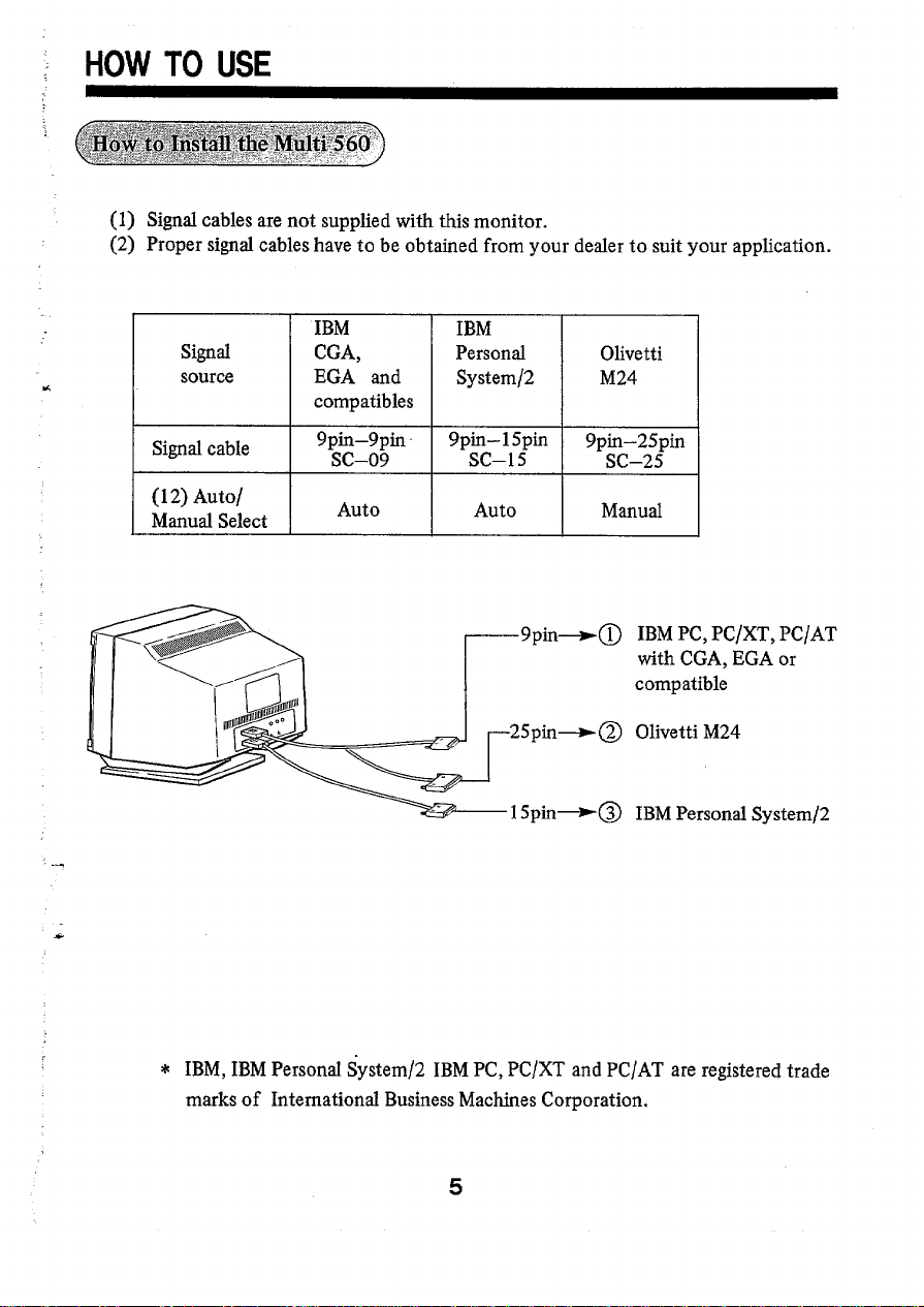
(1) Signal cables are not supplied with this monitor.
(2) Proper signal cables have to be obtained from
IBM IBM
Signal CGA, Personrd
source
EGA and
compatibles
System/2
your dealer to suit your application.
Olivetti
M24
Signal cable
(12) Auto/
Manual Select
9pin-9pin 9pin-15pin
SC–09
Auto Auto Manual
SC–15
9pin-+@ IBM PC, PC/XT, PC/AT
‘ph-@ 0’vettiM24
5pin+@ IBM Personal System/2
9pin-25pin
SC–25
with CGA, EGA or
compatible
* IBM, IBM Personal System/2 IBM PC, PC/XT and PC/AT are registered trade
marks of International Business Machines Corporation.
5
Page 6

Location and Description of User Controls
‘-
+
❑
(
11111111111111]l[lllllllllllll
mlllltllllllltllllll~ln-
@ POWER SWITCH
Press to turn the power ON. Press again
@ POWER ON INDICATOR
A green light comes on when the power is ON.
@ HORIZONTAL PHASE CONTROL
This control adjust the horizontal position of the display data.
At the extreme sides of control the display data may wrap around depending the signal
timing. Adjust to avoid this.
to turn the power OFF.
@ BRIGHTNESS CONTROL
While receiving analogue signals, this controls background raster brightness. Adjust the
background to the position where the background is just diminished.
While receiving TTL signals, this controls the brightness level of the whole signal. Adjust
this to obtain required brightness.
@ CONTRAST CONTROL
While receiving analogue signals, this controls the brightness of data (including background
colour). Adjust this to obtain the required brightness.
While receiving TTL signal this controls the brightness differences between low and high
intensity colours (16 colour mode) or between primary and secondary colours (64 colour
mode).
@ TEXT SWITCH
Pressing this control switches the screen from full colour to single amber colour while
receiving TTL signal input.
Press it again changes screen back to full colour.
c
Page 7

Q!E%$TTL/ANALoGuEs~TcH
By pressing this switch, input signals can be selected between analogue and TTL.
* Avoid supplying both analogue and TTL signals at the same time since this may cause
interferences between the signals (cross-talk). Both connectors can be connected at the
same time.
Q HORIZONTAL SIZE CONTROL
This controls the horizontal size.
_
This controls the vertical size.
e VERTICAL CENTERING CONTROL
This controls the vertical position of the data display.
- 16/64 COLOUR SELECT
When pressed in, the 64 colour mode is selected.
When set out, the 16 colour mode is selected.
When the AUTO mode is selected by the switch @ . This colour select does not work.
Instead, the monitor select 16 or 64 colour as standard EGA monitor.
@@l?@ AuTo/MANuAL SELECT
When it is pressed out, the auto mode is selected. When the auto mode is selected, the
Multi 560 automatically adjust to the IBM graphics board requirements including Personal system/2.
When set in, the manual mode is selected.
The display size is proportional to the signal. When the signal timing is differ from a fried
size, size controls 8 and 9 should be adjusted to obtain the required size. These controls
may not be capable for complete controls depending on the signal supplied.
_ TTL INPUT TERMINAL
Connect TTL output of the computer.
e ANALOGUE ~p~ TE~~AL
Connect analogue output of the computer.
@@@ AC ~LET
Connect a suitable cord set for your power outlet.
Some units are supplied with a proper power cord.
Some are NOT.
VERTICAL SIZE CONTROL
/
@ TILT& SWIVEL BASE
Refer to page 14.
7
Page 8

When signals other than the recommended signal are received
.,
Cause
Phenomenon
Adjustment
Picture width too
wide.
Data display period is more than standard timing.
D
Adjust horizontal size control @) .
Picture width too
narrow.
B
Data display period is less than standard timing.
Adjust horizontal size control @ .
Picture deviates to
the right.
Horizontal front porch is greater than standard timing.
Adjust horizontal phase control @ .
u
Picture deviates to
the left. Horizontal front porch is less than standard timing.
m
Adjust horizontal phase control @ .
Height of picture too
short.
Vertical blanking period is more than standard timing.
‘.
w
a
Adjust vertical size control @ .
Q
Page 9

Phenomenon
-1
Cause
Adjustment
Picture length
much extended.
too
$,
.,
..
, :.
,,
..
,’
-.,.-,
.,-
f
.:
[m]
. . .. .
Picture deviates
upward.
,,. ,..
:J:
J
..
m
Picture deviates
downward.
,,s“L..,,.S,alt.,u>$::.
“~;~::;,~;~:33},f$~,1~,z,,
.- .,,~, .,
[=1
..,.
Vertical blanking period is less than standard timing.
Adjust verticil sizecontrol @) .
Vertical front porch is less than standard timing.
Adjust vertical centering control
Vertical front porch is greater than standard timing.
Adjust vertical centering control @ .
@.
Note: Adjustment range has its design limit which may not cover the timing you would
/a
like to see on the display.
Page 10

SPECIFICATIONS
‘====)
CRT
Input Signal
Scanning frequency
Resolution
Video bandwidth
Display size
Linearity
Misconvergence
Video
sync
14”, 90-deg., In-Line, 0.31 mm dot pitch P22,
Tinted glass (55%), Non-Glare (Silica)
Analogue
0.6Vp-p/75-ohm positive
R, G, B
H/V composite
TTL
Horizontal
Vertical : 15-80 Hz
Horizontal
Vertical
30 MHz
240 (H) x 180 (V) mm
+/– 10%
Center
Corners
: 15.5 -35kHz
: 800 dots
: 560 lines
: 0.4 mm Max.
: 0.6 mm Max.
or
TTL level positive
R, G, B, I (16-colour) or
R, r, G, g, B,b
H, V separate TTL
TTL
(64-colour)
9,
Power input
Connector
Power consumption
Dimensions (W x H x D)
Weight
Specifications are subject to change without notice.
AC 220/240 V, 50 Hz
9-pin DB-9 for TTL and analogue
80W
358 x 362 x 389mm
14kg
10
Page 11

(1) TTL input
PIN No.
1
2
3
4
5
6
7
8
9
(2) Analog input
PIN No.
1
2
3
4
5
6
7
8
9
CGA 16-colour
Ground
No Connection
Red
Green
Blue
Intensity
Not comected
Horizontal Sync
Vertical Sync
PGA
Red
Green
Blue
Composite Sync
Mode control
Red Ground
Green Ground
Blue Ground
Ground
EGA 16/64-colour
Ground
Secondary Red
Primary Red
Primary Green
Primary Blue
Secondary Green
Secondary Blue
Horizontal Sync
Vertical Sync
~$c” Lpersond ‘ystem/2
E-1$’
@ , Red
~-Green
~~y,d Blue
ff#E Horizontal Sync
~ Vertical Sync
~f.@ Red Ground
Green Ground
Blue Ground
Ground
Red, Green & Blue Video= 0.6 Vp-p
Sync
= TTL level
11
Page 12

SEPARATE SYNC.
~
HORIZONTAL
VERTICAL
m 15.75kHz
AIM
~ BJLS 5.08
Cps
“~
DIM
s
EVS 4.4
Oms
% Pms 0.26
“: Qms 1.6
+ -
Rms 13.84
Sms 0.9
63.5 40.28 33.2
7.62 2.80 2.86
46.3
16.6
I
VIDEO
4-+
~
A
VIDEO
o
TIMING EXAMPLE AT MANUAL POSITION
EXAMPLEOF TIMING
24.83kHz 30.lkHz
64.5 to 28.6/Js(15.5 to 35kHz)
3.04 3.43 2 to 1o/.ls
2 to 8.151M
32.4
2.04 1.14
17.72 17.66 12.5 to 20.Oms(50 to 80 Hz)
0.32
1.01 0.73
16.11 16.6
0.28 0.066 0 to 1.6ms and Q=[(O-R9-O.8] /2*0.2
25.76
0.26
20 to 52.2/.s
1 ‘0 6“6PSRange 1:E/(B+C)=O.3to 0.5
0.05 to 0.7ms
0.08 to 2.2ms
12 to 17ms and (0- R)=O.8 to 4.0
and E/(B+C)=0.1 to 0.45
I
w
+
REMARKS
I
I
O, A= Total
P, B = Sync width Q, E = Front porch
S, C = Backporch
R, D= Display period
12
Page 13

TTL
Timing List at Auto Position
Type CGA
Resolution 320
m
kHz Front porch 6.65
I us Svnc width I
I us Distdav time ] 44.3
USTotal I 63.7
1
Usfv I 60
I
Hz Front porch
H Sync width 3
H Back porch 34
H Display time
1H Total I
H H. Sync P
V. Sync
X 200 640 X 350
15.70
4.6
8.15
25 0
200
262
P
Analogue
Type
Resolution
m
Front porch (w)
Sync width (w) 4.60 4.60 3.81
Back porch (us) 2.60 2.60
Display time(#s)
Total
W
Front porth (H) 42
Sync width (H) 2
Back porch (H)
Display time (H) 400
Total
H. Sync Comp
V. Sync
(kHz)
(#s)
(Hz) 60
PGA
X 400 640 X 480 320 X 400
640
30.48
o
25.60
32.80 32.80 31.75
24
508
“’
(H)
PGA
30.48 31.5 31.5
25.60 25.4
60
24 33
480 400
508
Comp
0 0.95
2 13
2 2 2 2 2
EGA
21.85
0
I
I
I
4,9
1.6
39,3 I
I 45.8 I
I 60 I
13
3
350
I
Ps/2-l Ps/2-2 PS/2-3 Ps/2-4
640
X 350 640 x 480 720 x 400
1,27 1.27 1.587
3.81
1.59
70 70
448 448 524 448
N
P
1.27 1.27 0.9525
25.4
31.75
38 11
58
350 480
P N
N N
366
P
N
31.5
3.81 3.81
25.4 25.4
31.75 31.75
60
31 33
400
31.5
70
13
N
I
I
I
P
Page 14

How to Remove or Install a Tdt /Swivel Stand
You can set the colour monitor to the desired angle with the tilt stand supplied.
CAUTION – This colour monitor may be used only with HITACHI exclusive tilt stand.
Use with other tilt stands may result in instability causing possible injury.
If you change the direction of monitor or operating condition, may cause impeTfect
colour uniformity because of the influence of earth ma~etism. This is not failure.
If you are worried about it, turn the power off and on again at an interval of 20-30
minutes or more after the power on to activate the internal auto degaussing.
(1) Install the tilt stand at the bottom of
the colour monitor.
(2) Fix the stand at 2 positions using
screws.
14
Page 15

MEMO
.
15
..
Page 16

—
—
460373
TAC
l-l
Printed in Japan YN-N {B)
 Loading...