

Page 1

PA
4.27.06
SM00002
REVISION 2
08.03.06
CH 1
Part Numbers Added
CH 2
08.04.06
Parts List Revised
08.09.06
Part Numbers Added
CH 3
08.22.06
CH 4
Revised Instructions for DCAM access via remote.
08.23.06
CH 5
Corrected Page number for DCAM access.
11.06.06
Correction made to CH 3
CH 6
CH 7
01.24.07
Added part numbers for Focus Pack
02.13.07
Revised Cut Off adjustment Instructions.
CH 8
Revised Phase Data Adjustment Procedure; step 3 and 8
03.13.07
CH 9
03.13.07
CH 10
Revised Instructions for DCAM access via remote.
No. 0216
51F59 DP65 51F59A/J DP65G
57F59 DP65 57F59A/J DP65G
SERVICE MANUAL
NNTTSSCC
65F59 DP65 65F59A/J DP65G
DP65 & DP65G
R/C: CLU-4361S
CChhaassssiiss
SERVICE MANUAL REVISION HISTORY INFORMATION
DATE REVISON # REASON
Mar , 06 SM00001 FIRST ISSUE OF MANUAL
05.03.07 CH 11 Changed text Increase > Decrease
06.20.07
CH 12
Added links to "TBD" designations in Exploded Views
SPECIFICATIONS AND PARTS ARE SUBJECT TO CHANGE FOR IMPROVEMENT
PROJECTION COLOR TELEVISION
MARCH 2006 HHEA-MANUFACTURING DIVISION
Page 2

No. 0216
PA
No.
51F59 DP65 51F59A/J DP65G
57F59 DP65 57F59A/J DP65G
SERVICE MANUAL
NNTTSSCC
65F59 DP65 65F59A/J DP65G
DP65 & DP65G
R/C: CLU-4361S
CChhaassssiiss
TO GO TO A CHAPTER, CLICK ON ITS HEADING BELOW
CONTENTS
IMPORTANT SAFETY INSTRUCTIONS.............................................................................. 2
SERVICING PRECAUTIONS .............................................................................................. 6
TECHNICAL CAUTIONS.................................................................................................... 11
SPECIFICATIONS.............................................................................................................. 13
GENERAL INFORMATION..................................................................................................15
REMOTE CONTROL GUIDE ...............................................................................................21
SERVICE ADJUSTMENTS .................................................................................................29
PROTECTION CIRCUIT BLOCK DIAGRAM ......................................................................82
TROUBLESHOOTING FLOW CHART ................................................................................83
BLOCK DIAGRAM .............................................................................................................88
CONNECTION DIAGRAM ........................................................................................................89
COMPONENT LOCATION DRAWING ...................................................................................90
FINAL WIRING DIAGRAM ....................................................................................................95
QUICK DISASSEMBLY GUIDE ......................................................................................................101
WAVEFORMS ............................................................................................................113
DC VOLTAGE TABLES ......................................................................................................118
CIRCUIT SCHEMATIC DRAWING .......................................................................................................121
PRINTED CIRCUIT BOARDS ...........................................................................................143
REPLACEMENT PARTS LIST ..........................................................................................155
QUICK REFERENCE PARTS LIST (IC & UNIT) ..............................................................180
CAUTION: These servicing instructions are for use by qualified service personnel only. To reduce the risk of
electric shock do not perform any servicing other than that contained in the operating instructions
unless you are qualified to do so. Before servicing this chassis, it is important that the service
technician read the “IMPORTANT SAFETY INSTRUCTIONS” in this service manual.
SAFETY NOTICE
USE ISOLATION TRANSFORMER WHEN SERVICING
Components having special safety characteristics are identified by a on the schematics and on the parts list in this
Service Data and its supplements and bulletins. Before servicing the chassis, it is important that the service technician
read and follow the “Important Safety Instructions” in this Service Manual.
!
SPECIFICATIONS AND PARTS ARE SUBJECT TO CHANGE FOR IMPROVEMENT
PROJECTION COLOR TELEVISION
MARCH 2006 HHEA-MANUFACTURING DIVISION
Page 3

DP65
IMPORTANT SAFETY INSTRUCTIONS
USE ISOLATION TRANSFORMER WHEN SERVICING
Components having special safety characteristics are identified by a on the schematics and on the parts list in this service manual
and its supplements and bulletins. Before servicing this chassis, it is important that the service technician read and follow the
“Important Safety Instructions” in this Service Manual.
For continued X-Radiation protection, replace picture tube with original type or Hitachi approved equivalent type.
This Service Manual is intended for qualified service technicians; it is not meant for the casual do-it-yourselfer. Qualified
technicians have the necessary test equipment and tools, and have been trained to properly and safely repair complex products
such as those covered by this manual.
Improperly performed repairs can adversely affect the safety and reliability of the product and may void warranty. If you are not
qualified to perform the repair of this product properly and safely, you should not risk trying to do so and refer the repair to a
qualified service technician.
!
WARNING
This product contains lead. Dispose of this product in accordance with applicable environmental laws. For
product recycling and disposal information, contact you local government agency or the Electronic Industries
Alliance at www.eiae.org (in the US) or the Electronic Product Stewardship Canada at www.epsc.ca (in Canada).
For more information, call “1-800-HITACHI.
Lead in solder used in this product is listed by the California Health and Welfare agency as a known reproductive toxicant which may
cause birth defects or other reproductive harm (California Health and Safety Code, Section 25249.5).
When servicing or handling circuit boards and other components which contain lead in solder, avoid unprotected skin contact with solder.
Also, when soldering do not inhale any smoke or fumes produced.
This television receiver provides display of television closed captioning in accordance with section 15.119 of the FCC rules.
Do not place any objects on the top of the television which may fall or cause a child to climb to retrieve the objects.
Projection TV’s are heavy and can mark or damage floor surfaces (especially wood flooring) if moved improperly. Do not slide or
force TV into position. Always roll TV allowing casters at bottom of unit to help steep and position the TV.
PREVENTION OF SCREEN BURN
This wide screen TV is designed to display wide screen pictures. Images hould be viewed mostly in wide screen format or zoomed to
fit the screen with moving pictures. Use of side panels, top and bottom panels of standard picture formats should only be 15% of your
total viewing time to prevent uneven aging of the phosphors. Phosphors in the lighted area of the picture will age more rapidly than
the gray areas. Continuous on-screen displays such as video games, stock market quotations, computer generated grphics, and
other fixed (non-moving) patters can cause permanent damage to television receivers. Such “SCREEN BURNS” constitute misuse
and are NOT COVERED by your HITACHI Factory Warranty.
PUBLIC VIEWING OF COPYRIGHTED MATERIAL
Pulic viewing of programs broadcast by TV stations and cable companies, as well as prgrams from other sources, may require prior
authorization from the broadcaster or owner of the video program material.
This product incorporates copyright protection technology that is protected by U.S. patents and other intellectual property rights. Use
of this copyright protection technology must be authorized by Macrovision Corporation, and is intended for home and other limited
consumer uses only unless otherwise authorized by Mcrovision. Reverse engineering or disassembly is prohibited.
FEDERAL COMMUNICATIONS COMMISSION NOTICE
This equipment has been tested and found to comply with the limits for a Class B digital device, pursuant to Part 15 of the FCC
Rules. These limits are designed to provide reasonable protection against harmful interference in a residential installation. This
equipment generates, uses, and can radiate radio frequency energy and, if not installed and used in accordance with the instructions,
may cause harmful interference to radio communications. However, there is no guarantee that interference will not occur in a
particular installation. If this equipment does cause harmful interference to radio or television reception, which can be determined by
turning the equipment off and on, the user is encouraged to try to correct the interference by one or more of the following measures:
• Reorient or relocate the receiving antenna.
• Increase the separation between the equipment and the receiver.
• Connect the equipment into an outlet on a circuit different from that to which the receiver is connected.
• Consult the dealer or an experienced radio/television technician for help.
This digital television is capable of receiving analog basic, digital basic cable television programming by direct connection to a cable
system providing such programming.
2
TABLE OF CONTENTS
Page 4
IMPORTANT SAFETY INSTRUCTION
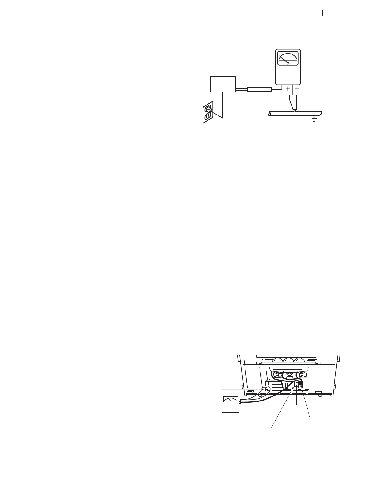
LEAKAGE
CURRENT
TESTER
(READING
SHOULD NOT
BE ABOVE 0.5MIU)
EARTH
GROUND
TEST ALL
EXPOSED
METAL SURFACES
DEVICE
UNDER
TEST
2-WIRE CORD
ALSO TEST WITH PLUG
REVERSED
(USING AC ADAPTER
PLUS AS REQUIRED)
Chassis
ground
High Impedance
H.V. meter
Deflection P.W.B.
FBT
(TH02)
High voltage
connector
1. Before returning an instrument to the customer, always
make a safety check of the entire instrument, including
but not limited to the following items.
a. Be sure that no built-in protective devices are
defective and/or have been deleted during servicing.
(1) Protective shields are provided on this chassis to
protect both the technician and the customer.
Correctly replace all missing protective shields,
including any removed for servicing convenience. (2)
When reinstalling the chassis and/or other assembly
in the cabinet, be sure to put back in place all
protective devices, including but not limited to,
nonmetallic control knobs, insulating fishpaper,
adjustment and compartment covers/shields, and
isolation resistor/capacitor networks.
this instrument or permit it to be operated without
all protective devices correctly installed and
functioning. Servicers who defeat safety features
or fail to perform safety checks may be liable for
any resulting damage.
b. Be sure that there are no cabinet openings through
which an adult or child might be able to insert their
fingers and contact a hazardous voltage. Such
openings include, but are not limited to (1) spacing
between the picture tube and cabinet mask, (2)
excessively wide cabinet ventilation slots, and (3) an
improperly fitted and/or incorrectly secured cabinet
back cover.
Antenna Cold Check – With the instrument AC plug
c.
removed from any AC source, connect an electrical
jumper across the two AC plug prongs. Place the
instrument AC switch in the on position. Connect one
lead of an ohmmeter to the AC plug prongs tied
together and touch the other ohmmeter lead in turn to
each tuner antenna input, exposed terminal screw
and, if applicable, to the coaxial connector. If the
measured resistance is less than 1.0 megohms or
greater than 5.2 megohms, an abnormality exists that
must be corrected before the instrument is returned to
the customer. Repeat this test with the instrument AC
switch in the off position.
Do not operate
DP65
AC Leakage Test
ANY MEASUREMENTS NOT WITHIN THE LIMITS
SPECIFIED HEREIN INDICATE A POTENTIAL
SHOCK HAZARD THAT MUST BE ELIMINATED
BEFORE RETURNING THE INSTRUMENT TO THE
CUSTOMER OR BEFORE CONNECTING THE
ANTENNA OR ACCESSORIES.
e. High Voltage – This receiver is provided with a hold
down circuit for clearly indicating that voltage has
increased in excess of a predetermined value.
Comply will all notes described in this Service Manual
regarding this hold down circuit when servicing, so
that this hold down circuit may correctly be operated.
Service Warning – With maximum contrast, operating
f.
high voltage in this receiver is lower than
32.0 kV. In
case any component having influence on high voltage
is replaced, confirm that the high voltage with
maximum contrast is lower than
32.0 kV.
To measure H.V. use a high impedance H.V. meter.
Connect (-) to chassis earth and (+) to the CRT anode
button. (See the following connection diagram.)
Note: Turn power switch off without fail before the
connection to the anode button is made.
Leakage Current Hot Check – With the instrument
d.
completely reassembled, plug the AC line cord
directly into a 120V AC outlet. (Do not use an isolation
transformer during this test.) Use a leakage current
tester or a metering system that complies with
American National Standards Institute (ANSI) C101.0
Leakage Current for Appliances and Underwriters
Laboratories (UL) 6500, (9.1.1). With the instrument
AC switch first in the on position and then in the off
position, measure from a known earth ground (metal
waterpipe, conduit, etc.) to all exposed metal parts of
the instrument (antennas, handle bracket, metal
cabinet, screw heads, metallic overlays, control
shafts, etc.), especially any exposed metal parts that
offer an electrical return path to the chassis. Any
current measured must not exceed 0.5 MIU. Reverse
the instrument power cord plug in the outlet and
repeat test.
3
Page 5

Shield Plate A
Glass Lens for Shielding
Shield Plate B
Shield Plate C
Shield Plate D
Detailing X-radiation shield
Shield Plate C
IMPORTANT SAFETY INSTRUCTIONS
DP65
g. X-radiation – TUBE: The primary source of X-
radiation in this receiver is the picture tube. The tube
utilized for the above mentioned function in this
chassis is specially constructed to limit X-radiation
emissions.
For continued X-radiation protection, the replacement
tube must be the same type as the original, Hitachi
approved type.
When troubleshooting and making test measurements in a receiver with a problem of excessive high
voltage, avoid being unnecessarily close to the picture tube and the high voltage component.
Do not operate the chassis longer than is necessary
to locate the cause of excessive voltage.
RED PRT ASS'Y
GREEN PRT ASS'Y
BLUE PRT ASS'Y
X-radiation Shield –
h.
1. This receiver is provided with X-ray shield plates
for protection against X-radiation. Do not remove
X-ray shield plates A, B, or C shown in Fig. 1
unnecessarily, when troubleshooting and/or
making test measurements.
2. To prevent X-radiation, after replacement of
picture tube and lens, confirm these components
to be fixed correctly to bracket and cabinet, and
not to be taken off easily.
Fig. 1. Installation of shield lens, shield cover and shield plates (oblique view).
4
Page 6

IMPORTANT SAFETY INSTRUCTIONS
DP65
2. Read and comply with all caution and safety-related
notes on or inside the receiver cabinet, on the
receiver chassis, or on the picture tube.
Design Alteration Warning – Do not alter or add to
3.
the mechanical or electrical design of this TV receiver.
Design alterations and additions including but not
limited to circuit modifications and the addition of
items such as auxiliary audio and/or video output
connectors, might alter the safety characteristics of
this receiver and create a hazard to the user. Any
design alterations or additions may void the
manufacturer’s warranty and may make you, the
servicer, responsible for personal injury or property
damage resulting therefrom.
Picture Tube Implosion Protection Warning – The
4.
picture tube in this receiver employs integral
implosion protection. For continued implosion
protection, replace the picture tube only with one of
the same type number. Do not remove, install, or
otherwise handle the picture tube in any manner
without first putting on shatterproof goggles equipped
with side shields. People not so equipped must be
kept safely away while picture tubes are handled.
Keep the picture tube away from your body. Do not
handle the picture tube by its neck.
7. Components, parts, and/or wiring that appear to have
overheated or are otherwise damaged should be
replaced with components, parts, or wiring that meet
original specifications. Additionally, determine the
cause of overheating and/or damage and, if
necessary, take corrective action to remove any
potential safety hazard.
PRODUCT SAFETY NOTICE – Many TV electrical
8.
and mechanical parts have special safety-related
characteristics some of which are often not evident
from visual inspection, nor can the protection they
give necessarily be obtained by replacing them with
components rated for higher voltage, wattage, etc.
Parts that have special safety characteristics are
identified in Hitachi service data by shading on
schematics and by a in the parts list. Use of
substitute replacement that does not have the same
safety characteristics as the recommended replacement part in Hitachi service data parts list might
create shock, fire, and/or other hazards. Product
safety is under review continuously and new
instructions are issued whenever appropriate. For the
latest information, always consult the appropriate
current Hitachi service literature. A subscription to, or
additional copies of service literature may be obtained
at a nominal charge from Hitachi.
!
Hot Chassis Warning – a. Some TV receiver chassis
5.
are electrically connected directly to one conductor of
the AC power cord and may be safely serviced
without an isolation transformer only if the AC power
plug is inserted so that the chassis is connected to the
ground side of the AC power source. Confirm that the
AC power plug is inserted correctly with an AC
voltmeter by measuring between the chassis and a
known earth ground. If a voltage reading in excess of
1.0V is obtained, remove and reinsert the AC power
plug in the opposite polarity and again measure the
voltage potential between the chassis and a known
earth ground.
have 85V AC (RMS) between chassis and earth
ground regardless of the AC plug polarity. These
chassis can be safely serviced only with an isolation
transformer inserted in the power line between the
receiver and the AC power source, for both personnel
and test equipment protection. c. Some TV receiver
chassis have a secondary ground system in addition
to the main chassis ground. This secondary ground
system is not isolated from the AC power line. The two
ground systems are electrically separated by
insulating material that must not be defeated or
altered.
6. Observe original lead dress. Take extra care to assure
correct lead dress in the following areas:
sharp edges,
that leads and components do not touch thermally hot
c. the AC supply, d. high voltage and e. antenna
parts,
wiring. Always inspect in all areas for pinched, out-ofplate, or frayed wiring. Do not change spacing
between components and the printed circuit board.
Check AC power cord for damage.
b. Some TV receiver chassis normally
a. near
b. near thermally hot parts – be sure
5
Page 7

SERVICING PRECAUTIONS
CAUTION: Before servicing instruments covered by this
service data and its supplements and addenda, read and
follow the “Important Safety Instructions” on page 3 of this
publication.
NOTE: If unforeseen circumstances create conflict between
the following servicing precautions and any of the safety
precautions on page 3 of this publication, always follow the
safety precautions. Remember: Safety First.
DP65
7. Do not apply AC power to this instrument and/or any of its
electrical assemblies unless all solid-state device heatsinks are correctly installed.
8. Always connect the test instrument ground lead to the
appropriate instrument chassis ground before connecting
the test instrument positive lead. Always remove the test
instrument ground lead last.
General Servicing Guidelines
1. Always unplug the instrument AC power cord from the AC
power source before:
a. Removing or reinstalling any component, circuit
board, module, or any other instrument assembly.
b. Disconnecting or reconnecting any instrument
electrical plug or other electrical connection.
c. Connecting a test substitute in parallel with an
electrolytic capacitor in the instrument.
CAUTION: A wrong part substitution or incorrect
polarity installation of electrolytic
capacitors may result in an explosion
hazard.
d. Discharging the picture tube anode.
2. Test high voltage only by measuring it with an appropriate
high voltage meter or other voltage measuring device
(DVM, FETVOM, etc.) equipped with a suitable high
voltage probe. Do not test high voltage by “drawing an
arc.” The H.V. Distribution Box has an internal 400M
resistor (bleeder resistor) connected from the high
voltage to ground. After power is removed from the
instrument the high voltage will discharge through the
high voltage bleeder resistor. If the tubes have high
voltage after power is removed, then the bleeder resistor
is defective or the bleeder ground is disconnected.
9. Use with this instrument only the test fixtures specified in
this service data.
CAUTION: Do not connect the test fixture ground strap
to any heatsink in this instrument.
Electrostatically Sensitive (ES) Devices
Some semiconductor (solid state) devices can be damaged
easily by static electricity. Such components commonly are
called Electrostatically Sensitive (ES) Devices. Examples of
typical ES devices are integrated circuits and some fieldeffect transistors and semiconductor “chip” components. The
following techniques should be used to help reduce the
incidence of component damage caused by static electricity.
1. Immediately before handling any semiconductor
component or semiconductor-equipped assembly, drain
off any electrostatic charge on your body by touching a
known earth ground. Alternatively, obtain and wear a
commercially available discharging wrist strap device,
which should be removed for potential shock reasons
prior to applying power to the unit under test.
Ω
2. After removing an electrical assembly equipped with ES
devices, place the assembly on a conductive surface
such as aluminum foil, to prevent electrostatic charge
buildup or exposure of the assembly.
3. Use only a grounded-tip soldering iron to solder or
desolder ES devices.
3. Discharge the picture tube’s anode at any of the R, G, or
B outputs on the H.V. Distribution Box only by (a) first
connecting one end of an insulated clip lead to the
degaussing or kine aquadag grounding system shield at
the point where the picture tube socket ground lead is
connected, and then (b) touch the other end of the
insulated clip lead to the picture tube high voltage
distribution box R, G, or B output, using an insulated
handle to avoid personal contact with high voltage.
4. Do not spray chemicals on or near this instrument or any
of its assemblies.
5. Unless specified otherwise in these service data, clean
electrical contracts by applying the following mixture to
the contacts with a pipe cleaner, cotton-tipped stick or
comparable nonabrasive applicator: 10% (by volume)
Acetone and 90% (by volume) isopropyl alcohol (90%99% strength).
CAUTION: This is a flammable mixture. Unless
specified otherwise in these service data,
lubrication of contacts is not required.
6. Do not defeat any plug/socket B+ voltage interlocks with
which instruments covered by this service data might be
equipped.
TABLE OF CONTENTS
4. Use only can anti-static type solder removal device.
Some solder removal devices not classified as “antistatic” can generate electrical charges sufficient to
damage ES device.
5. Do not use freon-propelled chemicals. These can
generate electrical charges sufficient to damage ES
devices.
6. Do not remove a replacement ES device from its
protective package until immediately before you are
ready to install it. (Most replacement ES devices are
packaged with leads electrically shorted together by
conductive foam, aluminum foil or comparable conductive
material.)
7. Immediately before removing the protective material from
the leads of a replacement ES device, touch the
protective material to the chassis or circuit assembly into
which the device will be installed.
CAUTION: Be sure no power is applied to the chassis or
circuit, and observe all other safety
precautions.
8. Minimize bodily motions when handling unpackaged
replacement ES devices. (Otherwise harmless motion
such as the brushing together of your clothes fabric or the
lifting of your foot from a carpeted floor can generate
static electricity sufficient to damage an ES device.)
6
Page 8

Use Solding Iron to Pry Leads
SERVICING PRECAUTIONS
General Soldering Guidelines
1. Use a grounded-tip, low-wattage soldering iron and
appropriate tip size and shape that will maintain tip
temperature within the range 500°F to 600°F.
DP65
Removal
1. Desolder and straighten each IC lead in one operation by
gently prying up on the lead with the soldering iron tip as
the solder melts.
2. Use an appropriate lead free solder (see page 10). Lead
solder can be used, but there is a possibility of failure due
to insufficient strength of the solder.
3. Keep the soldering iron tip clean and well-tinned.
4. Thoroughly clean the surfaces to be soldered. Use a
small wire-bristle (0.5 inch or 1.25 cm) brush with a metal
handle. Do not use freon-propelled spray-on cleaners.
5. Use the following desoldering technique.
a. Allow the soldering iron tip to reach normal
temperature (500°F to 600°F).
b. Heat the component lead until the solder melts.
Quickly draw away the melted solder with an antistatic, suction-type solder removal device or with
solder braid.
CAUTION: Work quickly to avoid overheating the
circuit board printed foil.
6. Use the following soldering technique.
a. Allow the soldering iron tip to reach normal
temperature (500°F to 600°F).
b. First, hold the soldering iron tip and solder strand
against the component lead until the solder melts.
c. Quickly move the soldering iron tip to the junction of
the component lead and the printed circuit foil, and
hold it there only until the solder flows onto and
around both the component lead and the foil.
CAUTION: Work quickly to avoid overheating the
circuit board printed foil or components.
2. Draw away the melted solder with an anti-static suctiontype solder removal device (or with solder braid) before
removing the IC.
Replacement
1. Carefully insert the replacement IC in the circuit board.
2. Carefully bend each IC lead against the circuit foil pad
and solder it.
3. Clean the soldered areas with a small wire-bristle brush.
(It is not necessary to reapply acrylic coating to areas.)
“Small-signal” Discrete Transistor Removal/Replacement
1. Remove the defective transistor by clipping its leads as
close as possible to the component body.
2. Bend into a “U” shape the end of each of three leads
remaining on the circuit board.
3. Bend into a “U” shape the replacement transistor leads.
4. Connect to replacement transistor leads to the
corresponding leads extending from the circuit board and
crimp the “U” with long nose pliers to insure metal to
metal contact, then solder each connection.
Power Output Transistor Devices Removal/Replacements
1. Heat and remove all solder from around the transistor
leads.
2. Remove the heatsink mounting screw (if so equipped).
3. Carefully remove the transistor from the circuit board.
d. Closely inspect the solder area and remove any
excess or splashed solder with a small wire-bristle
brush.
IC Removal/Replacement
Some Hitachi unitized chassis circuit boards have slotted
holes (oblong) through which the IC leads are inserted and
then bent flat against the circuit foil. When holes are the
slotted type, the following technique should be used to
remove and replace the IC. When working with boards using
the familiar round hole, use the standard technique as
outlined in paragraphs 5 and 6 above.
4. Insert new transistor in circuit board.
5. Solder each transistor lead, and clip off excess lead.
6. Replace heatsink.
Diode Removal/Replacement
1. Remove defective diode by clipping its leads as close as
possible to diode body.
2. Bend the two remaining leads perpendicularly to the
circuit board.
3. Observing diode polarity, wrap each lead of the new
diode around the corresponding lead on the circuit board.
4. Securely crimp each connection and solder it.
5. Inspect (on the circuit board copper side) the solder joints
of the two “original leads”. If they are not shiny, reheat
them and, if necessary, apply additional solder.
7
Page 9

CRIMP AND
SOLDER
BARE JUMPER
WIRE
Install Jumper Wire and Solder
DEFECTIVE
COPPER
REMOVED
Insulated Jumper Wire
SERVICING PRECAUTIONS
Fuses and Conventional Resistor Removal/Replacement
1. Clip each fuse or resistor lead at top of circuit board
hollow stake.
2. Securely crimp leads of replacement component around
stake 1/8 inch from top.
3. Solder the connections.
CAUTION: Maintain original spacing between the
replaced component and adjacent
components and the circuit board, to
prevent excessive component
temperatures.
Circuit Board Foil Repair
Excessive heat applied to the copper foil of any printed
circuit board will weaken the adhesive that bonds the foil to
the circuit board, causing the foil to separate from, or “liftoff,” the board. The following guidelines and procedures
should be followed whenever this condition is encountered.
In Critical Copper Pattern Areas
High component/copper pattern density and/or special
voltage/current characteristics make the spacing and
integrity of copper pattern in some circuit board areas more
critical than in others. The circuit foil in these areas is
designated as Critical Copper Pattern. Because Critical
Copper Pattern requires special soldering techniques to
ensure the maintenance of reliability and safety standards,
contact your Hitachi personnel.
DP65
At Other Connections
Use the following technique to repair defective copper
pattern at connections other than IC Pins. This technique
involves the installation of a jumper wire on the component
side of the circuit board.
1. Remove the defective copper pattern with a sharp knife.
Remove at least 1/4 inch of copper, to ensure hazardous
condition will not exist if the jumper wire opens.
2. Trace along the copper pattern from both wire sides of
the pattern break and locate the nearest component
directly connected to the affected copper pattern.
At IC Connections
To repair defective copper pattern at IC connections, use the
following procedure to install a jumper wire on the copper
pattern side of the circuit board. (Use this technique only on
IC connections.)
1. Carefully remove the damaged copper pattern with a
sharp knife. (Remove only as much copper as absolutely
necessary.)
2. Carefully scratch away the solder resist and acrylic
coating (if used) from the end of the remaining copper
pattern.
3. Bend a small “U” in one end of a small-gauge jumper wire
and carefully crimp it around the IC pin. Solder the IC
connection.
4. Route the jumper wire along the path of the cut-away
copper pattern and let it overlap the previously scraped
end of the good copper pattern. Solder the overlapped
area, and clip off any excess jumper wire.
3. Connect insulated 20-gauge jumper wire from the
nearest component on one side of the pattern break to
the lead of the nearest component on the other side.
Carefully crimp and solder the connections.
CAUTION: Be sure the insulated jumper wire is
dressed so that it does not touch
components or sharp edges.
Frequency Synthesis (FS) Tuning Systems
1. Always unplug the instrument AC power cord before
disconnecting or reconnecting FS tuning system cables
and before removing or inserting FS tuning system
modules.
2. The FS tuner must never be disconnected from the FS
tuning control module while power is applied to the
instrument.
3. When troubleshooting intermittent problems that might be
caused by defective cable connection(s) to the FS tuning
system, remove the instrument AC power as soon as the
defective connector is found and finish confirming the
bad connection with a continuity test. This procedure will
reduce the probability of electrical overstress of the FS
system semi-conductor components.
8
Page 10

SERVICING PRECAUTIONS
DP65
NOTE: These components are affixed with glue. Be careful not to break or damage any foil under the
component or at the pins of the ICs when removing. Usually applying heat to the component for a short
time while twisting with tweezers will break the component loose.
Leadless Chip Components
(surface mount)
Chip components must be replaced with identical
chips due to critical foil track spacing. There are no
holes in the board to mount standard transistors or
diodes. Some chip capacitor or resistor board solder
pads may have holes through the board, however the
hole diameter limits standard resistor replacement to
1/8 watt. Standard capacitors may also be limited for
the same reason. It is recommended that identical
chip components be used. .
Chip resistors have a three digit numerical resistance
code -1st and 2nd significant digits and a multiplier.
Example: 162 = 1600 or 1.6KΩ resistor, 0 = 0Ω
(jumper).
Chip capacitors generally do not have the value
indicated on the capacitor. The color of the component
indicates the general range of the capacitance.
Chip transistors are identified by a two letter code. The
first letter indicates the type and the second letter, the
grade of transistor.
Chip diodes have a two letter identification code as
per the code chart and are a dual diode pack with
either
common anode or common cathode. Check the parts
list for correct diode number.
Component Removal
1. Use solder wick to remove solder from component
end caps or terminals.
2. Without pulling up, carefully twist the component
with tweezers to break the adhesive.
3. Do not reuse removed leadless or chip
components since they are subject to stress
fracture during removal .
Chip Component Installation
1. Put a small amount of solder on the board
soldering pads.
2. Hold the chip component against the soldering
pads with tweezers or with a miniature alligator
clip and apply heat to the pad area with a 30 watt
iron until solder flows. Do not apply heat for more
than 3 seconds
TYPE
Chip Components
C
GRADE
SOLDER
CAPS
How to Replace Flat-lC
—Required Tools—
• Soldering iron • iron wire or small awl
• De-solder braids • Magnifier
1. Remove the solder from all of the pins of a Flat-lC
by using a de-solder braid.
Flat-IC
2. Put the iron wire under the pins of the Flat-lC and
pull it in the direction indicated while heating the
pins using a soldering iron. A small awl can be
used instead of the iron wire.
Iron
Wire
Pull
Soldering
Iron
Soldering
3. Remove the solder from all of the pads of the
Fiat-lC by using
a de-solder braid.
De-Solder
Braid
Flat-IC
4. Position the new Flat-lC in place (apply the pins of
the Flat-lC to the soldering pads where the pins
need to be soldered). Properly
determine the positions of the
soldering pads and pins by
correctly aligning the polarity
symbol.
5. Solder all pins to the soldering pads using a fine
tipped soldering iron.
De-Solder
Braid
Soldering
Iron
Awl
Iron
Soldering
Iron
Polarity Symbol
B
ANODES
E
COMMON CATHODE
MH DIODE
TRANSISTOR
SOLDER CAPS
1ST DIGIT
RESISTOR
CAPACITOR
2ND DIGIT
MULTIPLIER
= 1600 = 1.6K
Solder
Soldering
Iron
6. Check with a magnifier for solder bridge between
the pins or for dry joint between pins and soldering
pads. To remove a solder bridge, use a de-solder
braid as shown in the figure below.
De-Solder
Braid
Bridge
Solder
9
Soldering
Iron
Page 11

2006 models >> lead-free solder apply
Information for service about lead-free solder introduction
Hitachi introduced lead-free solder to conserve the "Earth Environment".
Please refer to the following before servicing.
(1)
Characteristic of lead-free solder
Melting point of lead free solder is 40-50oC higher than solder containing lead.
(2) Solder for service
Following composition is recommended.
" Sn - 3.0Ag - 0.5Cu " , or " Sn - 0.7 Cu "
Lead solder can be used, but there is a possibility of failure due to insufficient strength of the solder.
Caution when using solder containing lead.
Please remove previous solder as much as possible from the soldering point.
When soldering, please perfectly melt the lead-free solder to mix well with the previous solder.
(3) Soldering iron for lead-free solder.
Melting point of lead-free solder is higher than solder containing lead.
Use of a soldering tool "with temperature control" and "with much thermal capacitance" is recommended.
(Recommended temperature control : 320oC - 450oC)
Recommended temperature
PWB with chip parts
PWB without chip parts
Chassis, metal, shield etc.
320oC +/- 30oC
380oC +/- 30oC
420oC +/- 30oC
(4) Identification of lead-free PWB
2004 models
2005 models
>> lead-free solder is introduced
>> lead-free solder apply
DP65
On lead-free PWB, "F" is added at the beginning of stamp on PWB. (e.g. F DP65)
10
Page 12
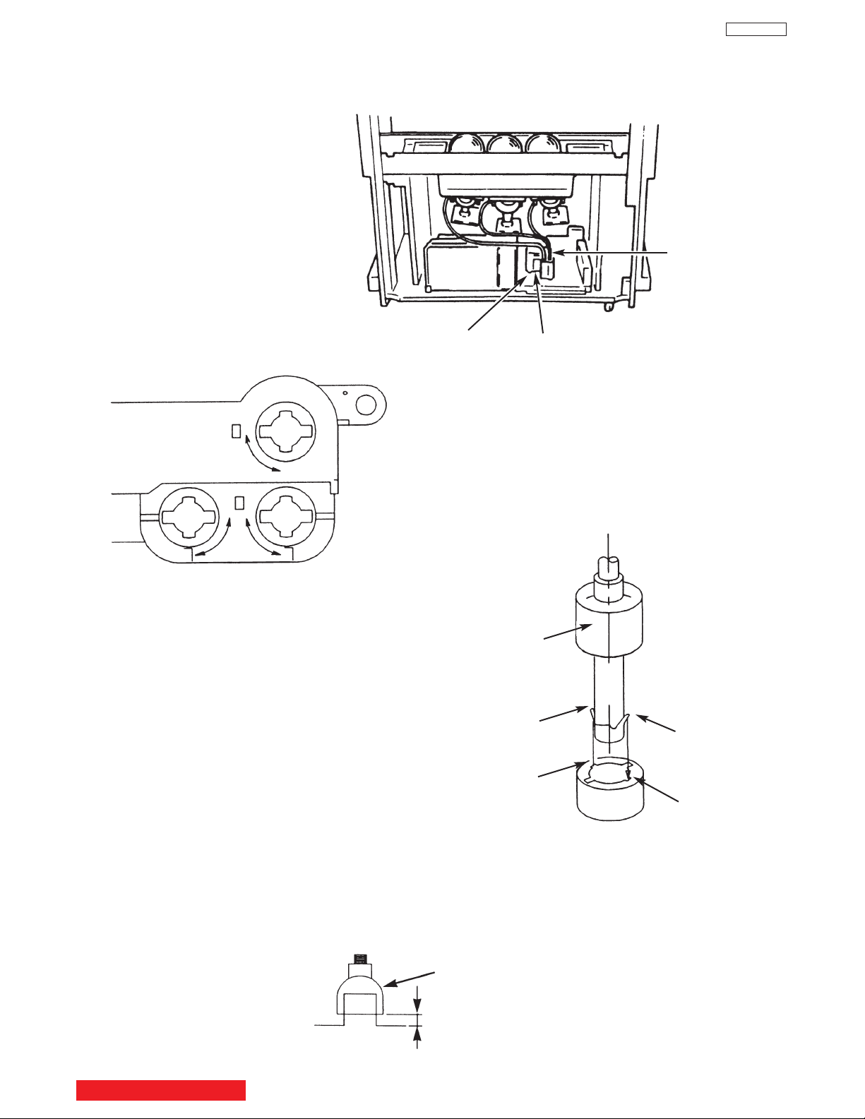
CAUTIONS WHEN CONNECTING / DISCONNECTING THE HV CONNECTOR
Perform the following when the
HV connector (anode connector)
is removed or inserted for CPT
replacement, etc.
DP65
TECHNICAL CAUTIONS
Anode
connector
Deflection P.W.B.
PUSH
PUSH
Fig. A
3. Remove the connector slowly
by pulling it away from the
case.
FBT
During Removal
1. Roll out silicon cover from FBT’s contact area slowly .
2. While turning the connector about 90 degrees
following the arrow (0 position), push the connector
slightly towards the case. (Fig. A)
Silicon cover
Wing
Wing
L Position
L Position
Fig. B
During Insertion
1. Please refer to direction for insertion as shown in Fig. B (L position). Insert connector until “CLICK” sound is heard.
2. Make sure the connector is pressed right in, so that it has a good contact with the spring.
3. Confirm the contact by pulling the connector slightly. (Don’t pull hard because it may damage the connector).
4. Cover the high voltage output by carefully pushing silicon cover onto it. (Don’t turn the connector).
(REMARK)
1. Make sure the silicon cover is
covering the high voltage output.
TABLE OF CONTENTS
Silicon Cover
less than 1mm
11
Page 13

TECHNICAL CAUTIONS
(TH02)
RH19
RH17
Fig. 2. Power/Deflection P.W.B
Remove RH19 and connect 50KΩ VR jig as shown.
TH02
FBT
50KΩ VR
50KΩ VR
33KΩ
Resistor
33KΩ
DP65
High Voltage limiter circuit operation check.
1. Turn off TV and connect jig as shown in Figure 2. Adjust
jig fully counter-clockwise for minimum resistance.
2. Set the AC input to 120V AC and turn on TV.
3. Confirm test pattern on CRT is a usable picture, then
slowly adjust jig until the picture disappears and TV shuts
down.
4. When the limiter circuit is operating properly, High
Voltage will be less than 37 kV at 1.62mAwhen TV shuts
down.
5. Turn off set immediately after checking circuit operation.
6. Unplug set for one minute to reset shutdown circuit.
Remove jig and voltmeter.
AC CORD POLARITY
This check is based on the UL standard. Use the jigs
specified by the production technology section. The
GND side (wider blade) of the AC power cord should
be connected to KKC2
R901
X901
L901
F901
WHITE side
WHITE side =
C901
GND side
TABLE OF CONTENTS
12
12
Tester
Page 14
125V
10A
F
10 A 125V
SPECIFICATIONS
DIMENSIONS:
51F710A 57F710A 65F710A
Height (in.) 50-3/8 54-9/16 59-15/16
(mm) 1,279.0 1,385.6 1,521.0
Width (in.) 48-3/4 54 61
(mm) 1,239.0 1,372.0 1,549.0
Depth (in.) 21-7/8 23-5/8 27-7/8
(mm) 557 599.4 708
Weight (lbs.) 187.4 205 309
(kg.) 85 93 140
DP65
Models: 51F59/A/J 57F59/A/J 65F59/A/J
Cathode-Ray Tube:
51F59A/J,57F59A/J,65F59A/J 51F59,57F59,65F59
R=P16MAB00RFA
G=P16MAB00HHA
B=P16LXL00BMB
B=P16MAB00BMB
Power Consumption:
• Power Consumption (operating)
51/57/65F59/A/J . . . . . . . . . . . . . . . . . . . . . .187W
• Power Consumption (maximum)
51/57/65F59/A/J . . . . . . . . . . . . . . . . . . . . . .235 W
Antenna Impedance: 75 Ohm Unbalanced
VHF / UHF / CATV
Receiving Channel: BAND CH
VHF 2~13
UHF 14~69
EXT. Mid (A-5)~(A-1), 4+
CATV Mid. A~I
CATV Super J~W
CATV Hyper (W+1)~(W+28)
CATV Ultra (W+29)~(W+94)
Available signal:
Cable ANALOG (NTSC : STD/IRC/HRC)
Air ANALOG (NTSC)
DIGITAL (ATSC:8VSB)
Intermediate Frequency: Picture l-F Carrier 45.75 MHz
Sound l-F Carrier 41.25 MHz
Color Sub Carrier 42.17 MHz
Video Input: 1 Volt p-p, 75 Ohm
Video Output: 1 Volt p-p, 75 ohm
Audio Input: 470 mVrms, 47 k Ohm
Stereo Audio Output: 470 mVrms, 1 k Ohm
Audio Output Power:
Front: 24 watts per channel at 10% distortion,
8 ohm Impedance. Max output 25 watts.
Anode Voltage:
DP65
31.7±0.2kv (1.59±0.2mA)
Brightness: 51” 57” 65”
(W/ ultra shield) 250cd/m2 195cd/m2 150cd/m2
(W/o ultra shield) 310cd/m2 240cd/m2 185cd/m2
Speakers: 51” 2 Woofers - 5 inch (12 cm) round
57” 2 Woofers - 6 inch (16 cm) round
65” 2 Woofers - 6 inch (16 cm) round
Circuit Board Assemblies:
CPT (B) P.W.B. Digital P.W.B.
CPT (G) P.W.B
CPT (B) P.W.B.
Power/Deflection P.W.B.
Signal P.W.B.
Sensor P.W.B.
DCU P.W.B.
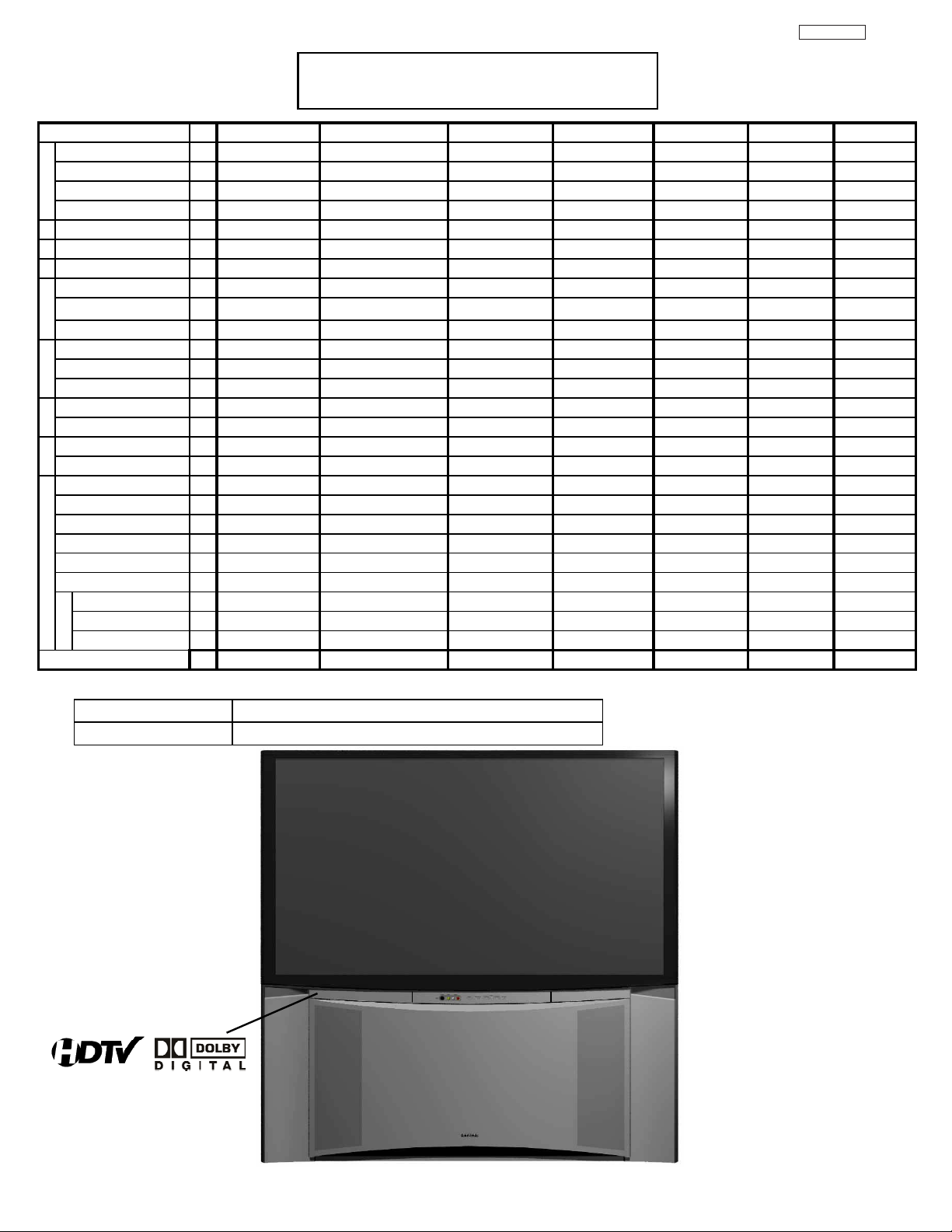
CIRCUIT PROTECTION
CAUTION: Below is an EXAMPLE only. See Replacement Parts List for details. The following symbol near the fuse
indicates fast operation fuse (to be replaced). Fuse ratings appear within the symbol.
Example:
The rating of fuse F901 is 10A - 125V.
“RISK OF FIRE - REPLACE FUSE AS MARKED”
TABLE OF CONTENTS
Replace with the same type fuse for continued protection
against fire.
13
13
Page 15
9
8
)
T
e
Feature Spec. Differences Sheet
DP65
Items
No
Screen Size(WxH) 1
Aspect Ratio 2
Set Diimension(WxHxD) 3
Dimension
Set Wight (Kg) 4
1239x1275x557 <-
Lens(RasterSize) 5
PRT 6
Mirror 7
n
n
Fresnel 8
e
e
e
e
cr
cr
Shield 9
S
S
Brightness/100% white 12
ATSC/Digital cable 13
POD 14
FE
NTSC tuner 15
Y/C separator(main) 16
Video
W/B mode 18
L-R SPEAKER 20
Audio
SOURROUND 22
Convertor(1H->2.14H) 23
PinP 24
Digital Module(Sein
DW(PiP/Split/12) DW(PiP/Split)
OSD 26
2/3 pull down 33
Feature
CONVERGENCE 34
MAGIC8+117+9+
REMOTE 35
MONITOR OUT 45
S VIDEO OUT 46
AUDIO TO Hi-Fi 47
Yes (Monitor out)
Model Year
Appearance SPECIFICATIONS
51F710A 51F59/A
51" 1129x635 <-
16:9 <-
85(Plastic cab) <-
HSB (5.0VW) D250 (5.0VW)
P16LXL00 BC MAB/LXL
1st surface 2nd surface
t=1.35 t=1.11 t=1.11 <- <-
t=1.35 t=1.11
Yes (HC) 81% No
260cd/m
2
300cd/m
2
1 ATSC only DTV-S
Yes No
1 Digital/Analog tuner
3DYC <-
4mode 3Mode
FR 12cm x 2 <-
X(SRS/BBE) No
Digital PWB(FC4)
BitMap 05& 04 comb.BitMap 05-B
No Yes
<-
TVUG New SMK
Yes AUDIO only
Yes No
Yes (Audio out)
2005 2006
57F59/A
57" 1262x710
<-
1372x1386x599
93(Plastic cab)
D250 (5.0VW)
<-
1st surface
<-
<-
No
240cd/m
2
<-
-
<-
<-
3Mode
16cm
<-
<-
<-
<-
Yes
<-
<-
<-
<-
<-
2006
65F59/A
65" 1439x809
<-
1549x1521x708
140(wood cab)
D260 (5.0VW)
<-
Ag mirror
<-
<-
No
2
185cd/m
<-
-
<-
<-
3Mode
<-
<-
<-
<-
<-
Yes
<-
<-
<-
<-
<-
2006
51F59J 57F59J 65F59J
51" 1129x635 57" 1262x710 65" 1439x809
<- <- <-
1239x1275x557 1372x1386x59
85(Plastic cab) 93(Plastic cab) 140(wood cab
D250 (5.0VW) D250 (5.0VW) D260 (5.0VW)
MAB/LXL <- <-
2nd surface 1st surface Ag mirror
t=1.11 <- <-
Yes (HC) 81% <- <-
250cd/m
2
1950cd/m
2
<- <- <-
---
<- <- <-
<- <- <-
3Mode 3Mode 3Mode
FR 12cm x 2 16cm <-
<- <- <-
<- <- <-
<- <- <-
<- <- <-
Yes Yes Yes
<- <- <-
<- <- <-
<- <- <-
<- <- <-
<- <- <-
2006 2006 2006
549x1521x70
150cd/m
2
PRODUCT : 2006 PTV F59 Series
MODEL :
65/57/51 F59/F59A/F59J
Monitor
14
Page 16

GENERAL INFORMATION
MENU/SELECT button
This button allows you to enter the MENU, making
it possible to set TV features to your preference
without using the remote. This button also serves
as the SELECT button when in MENU mode.
INPUT/EXIT button
Press this button to display the input menu,
CABLE, AIR, INPUT: 1, 2, 3, 4 and 5. This button
also serves as the EXIT button when in MENU
mode.
CHANNEL selector
Press these buttons until the desired channel
appears in the top right corner of the TV screen.
These buttons also serve as the cursor down (
)
and up (
) buttons when in MENU mode.
VOLUME level
Press these buttons for your desired sound level.
The volume level will be displayed on the TV
screen. These buttons also serve as the cursor left
(
) and right () buttons when in MENU mode.
When the TV power is turned OFF at a volume level
31 or greater, the volume level will default to 30
when the TV is turned ON. However, if it is set to a
level 30 or less, the volume level will be at the level
it was set when the TV is turned ON.
POWER button/ POWER LED
Press this button to turn the TV on or off. This LED
light is on during normal operation. At initial TV turn
on, the TV cannot receive any button or Remote
Control signals for approximately five seconds
while the internal programming is loading. This is a
normal default operation of this television and is an
energy saving feature.
MAGIC FOCUS button
Use this button to automatically adjust your picture
quality to optimum performance (see page 53).
FRONT INPUT JACKS (INPUT 5)
Use these audio/video jacks for a quick hook-up
from a camcorder or VCR to instantly view your
favorite show or new recording. Press the INPUT
button and select INPUT 5. If you have mono
sound, insert the audio cable into the left audio
jack.
IR RECEIVER Sensor
Point the remote control at this area when selecting
channels, adjusting volume, etc.
쐋
POWER
LED
DP65
TABLE OF CONTENTS
15
Page 17

DP65
쐃AIR /CABLE Input
CABLE – A 75-Ohm RF antenna or CATV (Cable
TV) input.
AIR – A 75-Ohm RF antenna input.
NOTE: You may ask your local cable company
whether DTV services are available.
쐇 Audio/Video INPUTS 1, 2, 3 and 4
By using the INPUTS button, CURSOR buttons
and SELECT button of the remote control you can
select each video source. Use the audio and video
inputs to connect external devices, such as VCRs,
camcorders, laserdisc players, DVD players etc. (If
you have mono sound, insert the audio cable into
the left audio jack.)
NOTE: You may use VIDEO or S-VIDEO inputs to
connect to INPUT 1 and 2, but only one of
these inputs may be used at a time.
쐋
Audio Out
These jacks provide fixed or variable audio
signals which are used for recording.
(see page 63).
쐏 S-Video INPUTS 1 and 2
INPUTS 1 and 2 provide S-Video (Super Video)
jacks for connecting equipment with S-Video
output capability.
쐄 Component: Y-P
BPR INPUTS
INPUTS 3 and 4 provide Y-P
BPR jacks for
connecting equipment with this capability, such as
a DVD player or Set Top Box. You may use
composite video signal for both inputs.
NOTE: 1. Do not connect composite VIDEO and
S-VIDEO to INPUT 1, 2 or 5 at the same
time. S-VIDEO has priority over VIDEO input.
2. Your component outputs may be labeled
Y, B-Y, and R-Y. In this case, connect the
components B-Y output to the TV’s P
B
input and the components R-Y output to
the TV’s P
R input.
3. Your component outputs may be labeled
Y-C
BCR. In this case, connect the component
C
B output to the TV’s PB input and the
component C
R output to the TV’s PR input.
4. It may be necessary to adjust TINT to
obtain optimum picture quality when using
the Y-P
BPR inputs (see page 32).
5. To ensure no copyright infringement, the
MONITOR OUT output will be abnormal,
when using the Y-P
BPR jacks.
6. INPUT 3 and INPUT 4 (Y/VIDEO) can be
used for composite video and component
video input.
쐂 HDMI1 (High Definition Multimedia
Interface) (INPUT 1)
ABOUT HDMI – HDMI is the
next-generation all digital interface for consumer
electronics. HDMI enables the secure distribution
of high-definition video and multi-channel audio in
a single cable. Because digital television (DTV)
signals remain in digital format, HDMI assures that
pristine high-definition images retain the highest
video quality from the source all the way to your
television screen.
Use the HDMI input for your external devices such
as Set-Top-Boxes or DVD players equipped with an
HDMI output connection.
HDMI, the HDMI logo and High-Definition
Multimedia Interface are trademarks or registered
trademarks of HDMI Licensing LLC.
NOTE: 1. The HDMI input is not intended for use
with personal computers.
2. Only DTV formats such as 1080i, 720p, 480i
and 480p are available for HDMI input.
쐃
쐇
쐋
쐏
쐄
쐂
쐆
쐊
쐎
GENERAL INFORMATION
16
Page 18

DP65
TV AS CENTER (INPUTS 1-4)
These jacks are for stereo amplifiers with center
signal output capability. This feature allows the TV
speakers to be used as a center speaker. The TV
must be set as a center channel by selecting TV
AS CENTER on the Internal Speakers Settings of
the Audio Menu (see page 38).
Optical Out (Digital Audio)
This jack provides Digital Audio Output for
your audio device that is Dolby
® Digital
compatible, such as an audio amplifier.
Manufactured under license from Dolby
Laboratories. “DOLBY” and the DOUBLE-D
symbol are trademarks of Dolby Laboratories.
Upgrade Card
This card slot is for future software upgrades.
Hitachi will notify you if a software upgrade is
required for your TV. In order to receive written
notification, please complete and return your
warranty card.
쐃
쐇
쐋
쐏
쐄
쐂
쐆
쐊
쐎
NOTE : This OUTPUT is for DIGITAL channels only.
GENERAL INFORMATION
17
Page 19

GENERAL INFORMATION
TIPS ON REAR PANEL CONNECTIONS
• S-VIDEO, Y- P
BPR and HDMI
connections are provided for
high performance laserdisc
players, VCRs etc. that have
this feature. Use these
connections in place of the
standard video connection if
your device has this feature.
• If your device has only one
audio output (mono sound),
connect it to the left audio
jack on the television.
• Refer to the operating guide of
your other electronic equipment
for additional information on
connecting your hook-up
cables.
• An AUDIO system can be used
by connecting the AUDIO TO HI-FI
output of the TV. This can be
use when you like to control the
volume output by changing the
volume of the TV.
• You may use VIDEO or
S-VIDEO inputs to connect to
INPUT 1, INPUT 2 or INPUT 5,
but only one of these may be
used at a time.
• Connect only one component
(VCR, DVD player, camcorder,
etc.) to each input jack.
• COMPONENT: Y- P
BPR (INPUT 3 and INPUT 4)
connections are provided for high performance
components, such as DVD players and set-topboxes. Use these connections in place of the
standard video connection if your device has this
feature. INPUT 3 and INPUT 4 accepts both
composite and component video signals.
• Your component outputs may be labeled Y, B-Y,
and R-Y. In this case, connect the components
B-Y output to the TV’s P
B input and the
components R-Y output to the TV’s P
R input.
• Your component outputs may be labeled Y- C
BCR.
In this case, connect the components C
B output to
the TV’s P
B input and the components CR output to
the TV’s P
R input.
• You may use composite and component video
signals for INPUT 3 and INPUT 4.
• It may be necessary to adjust TINT to obtain
optimum picture quality when using the Y-P
BPR
inputs (see page 34).
• To ensure no copyright infringement, the
MONITOR OUT output may be abnormal, when
using the Y- P
BPR jacks.
• When using an HDMI input from a Set-Top-Box, it
is recommended that a 1080i or 720p input signal
is used.
NOTE: 1. Connect only one component to each
input jack.
2. Follow connections that pertain to your
personal entertainment system.
3. INPUT 3 and INPUT 4 can accomodate
Composite and Component video signals.
4. Cables are not included with the purchase
of this TV, except when noted as
“provided”.
MACROVISION NOTES:
1. Video signals fed through a VCR may be
affected by copyright protection systems
and the picture will be distorted on the
television.
2. Connecting the television directly to the
Audio /Video output of a Set-Top-Box will
assure a more normal picture.
Outside Antenna
or Cable
DP65
External
Digital
Component
with HDMI
output
capability
HDMI OUT
OPTICAL IN
To an
amplifier/
receiver with
optical input
capability.
AUX/PHONO INPUT
L R
AUDIO AMP
OUTPUT
VL R
S-VIDEO
Laserdisc player, VCR,
OUTPUT
VL R
S-VIDEO
VCR #1 DVD Player
OUTPUT
18
RLPB/CB PR/CRY
Page 20

Match the numbers below to the diagram for
speaker placement.
The television’s internal speakers will act as
center speaker (select AUDIO - INTERNAL
SPEAKERS - TV AS CENTER).
These FRONT left and right speakers are
connected to the FRONT output of a
separate audio amplifier.
These REAR left and right speakers are
connected to the Rear output of a separate
audio amplifier.
This subwoofer is connected to the LFE/SUB
Out output of a separate audio amplifier.
NOTE: 1. The Optical Out (Digital Audio) provides a
fixed digital audio output to your external
component such as an A/V receiver with
optical input capability. The audio level
can only be controlled through the volume
control of the external audio amplifier.
2. See page 39 for AUDIO-Digital Output.
GENERAL INFORMATION
Connecting External Audio Sources
DP65
쐋쐋
RCA
Cable
Optical
Cable
CENTER
OUT
Stereo System Amplifier
or DVD Player
OPTICAL
IN
19
Page 21

Front Panel Jacks and Connections
The front panel jacks are provided as a convenience to allow you to easily connect a camcorder or VCR as shown
in the following examples:
NOTE: 1. Completely insert connection cord plugs when connecting to front panel jacks. If you do not, the
played back picture may be abnormal.
2. If you have a S-VHS VCR, use the S-INPUT cable in place of the standard video cable.
3. If you have a mono VCR, insert the audio cable into the left audio jack of your TV.
DP65
20
Page 22
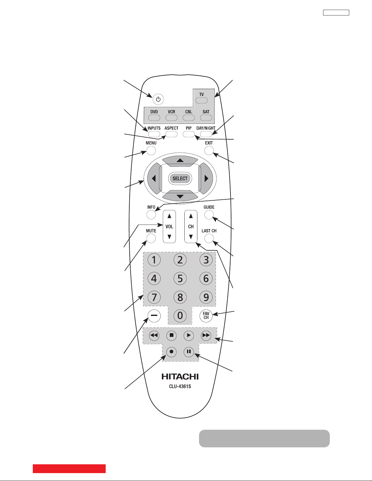
In addition to controlling all of the functions on your HITACHI Projection TV, the new remote control is designed to
operate different types of devices, such as, DVD Players, CBL (Cable Boxes), set-top-boxes, satellite receivers,
and VCRs. The remote control must be programmed to control the chosen device. Please see page 18-31 of the
Intruction Book for a complete description of all features and programming of the Remote Control.
LEGEND
TV – Television VCR – Video Cassette Recorder/Player
CBL – Cable Box DVD – Digital Video Disc Player
STB – Set-Top-Box SAT – Satellite Receiver
POWER BUTTON
(TV, CBL, VCR, DVD, SAT)
Turns the selected device on
and off.
INPUTS BUTTON (TV)
Accesses the INPUTS menu
system.
ASPECT BUTTON (TV)
Changes the aspect ratio while
watching TV.
MENU BUTTON
(CBL, DVD, SAT, TV)
Accesses the OSD menu
system.
CURSOR/SELECT BUTTONS
(TV, DVD, CBL, SAT)
The CURSOR buttons are used
to navigate the cursor through
the OSD and INPUTS menu
systems, and the SELECT
button is used to
Select/Activate the highlighted
menu item.
VOLUME BUTTONS (TV)
Adjusts the audio level of your
TV.
MUTE BUTTON (TV)
Reduces the audio level to 50%
if pressed once, and to
complete mute if pressed twice.
Press it a third time to restore
audio level.
NUMERIC BUTTONS
(TV, DVD, CBL, SAT, VCR)
Used to manually enter the TV
channel, and used for numeric
entry when navigating through
the OSD menu system.
(-) BUTTON (TV, SAT)
The (-) button is used when the
remote is in Set-Top-Box (STB)
mode or when the TV uses a
digital input.
RECORD BUTTON (VCR)
Press twice (2 times) to record
programs.
SOURCE ACCESS BUTTONS
(TV, DVD, VCR, CBL, SAT)
Changes the mode of the
Universal Remote Control to
control the device selected.
DAY/NIGHT BUTTON (TV)
Select picture mode settings
between DAY and NIGHT mode.
PIP BUTTON (TV)
Press to show and change the
Picture-in-Picture mode.
EXIT BUTTON
(TV, CBL, SAT)
Exits out of the OSD or INPUTS
menu systems if their menu is
displayed.
FAVORITE CHANNEL
(FAV CH) button (TV)
Press to enter/access Favorite
Channel (FAV) mode.
GUIDE BUTTON
(SAT/STB, CBL)
Accesses the program guide of
other devices.
INFO BUTTON
(TV, CBL, SAT)
Displays various information on
the screen.
CHANNEL BUTTONS
(TV, CBL, SAT, VCR)
Changes the channel.
LAST CHANNEL (LC) BUTTON
(TV, CBL, SAT)
Switches between the current
and last channel viewed.
DVD/VCR CONTROL
BUTTONS (DVD, VCR)
Controls the precode functions
of your VCR and DVD.
PAUSE BUTTON
(TV, VCR, DVD)
Press to show and change the
Freeze mode of the TV or pause
other devices.
NOTE: STB precode is included in the
SAT mode.
Quick Guide for the Remote Control
DP65
TABLE OF CONTENTS
21
Page 23

ASPECT button
Press this button to quickly change the picture format ASPECT ratio. Depending on the input signal format
received, the picture format ratio allows you to adjust the images through the following options.
• Antenna-Analog CH
• S-Video/Video Input
(Auto Aspect: Off)
• HDMI-480i/480p Input
(Auto Aspect: Off)
• Component-480i/480p
Input (Auto Aspect: Off)
• Antenna-Digital CH (4:3)
• S-Video/Video 4:3 Letter
Input (Auto Aspect: On)
• HDMI-480i/480p 4:3/
Letter Input (Auto Aspect: On)
• Component-480i/480p 4:3
Letter Input
(Auto Aspect: On)
• S-Video/Video 16:9 Input
(Auto Aspect: On)
• HDMI-480i/480p 16:9 Input
(Auto Aspect: On)
• Component-480i/480p
16:9 Input
(Auto Aspect: On)
• Antenna-Digital CH (16:9)
• HDMI-720p/1080i (16:9)Input
• Component-720p/1080i
(16:9)Input
NOTE:
1. All five video inputs have independent Aspect Style settings.
2. Vertical position adjustments are directly available when you choose 4:3
EXPANDED/ZOOM1/ZOOM2 or 16:9 ZOOM aspect style (see also page 40 of Instruction Book).
4:3 STANDARD
Use this aspect mode to display conventional (4:3)
images. Side panels (gray areas) are placed to the
left and right of the image to preserve the original
aspect ratio of the source. Note: Use this mode for
only 15% of your total viewing time to prevent
uneven aging of the phosphors. Phosphors in the
lighted area of the picture will age more rapidly
than the gray areas.
4:3 EXPANDED
Use this aspect mode to display conventional (4:3)
sources by linearly increasing image expansion
from the center towards the edges of the display
area in order to fill it.
4:3 ZOOM1/ZOOM2
Use these aspect modes to zoom in on
conventional (4:3) sources.
16:9 STANDARD
Use this aspect mode to display 16:9 sources like
HDTV and DVD’s preserving the original 16:9
aspect ratio.
16:9 ZOOM
Use this aspect to Zoom-in once while in 16:9
aspect.
DISPLAY PICTURE FORMAT
DP65
22
Page 24

Your HITACHI Projection TV incorporates one Tuner
technology designed for improved viewing enjoyment.
This Tuner feature allows you to view antenna input
on the main picture and a Video Input on sub-picture
simultaneously.
When an ANALOG channel or INPUT is viewed as
the main picture, an ANALOG channel or INPUT can
not be viewed as a sub picture.
To select between main picture and PIP sub-picture
use the CURSOR buttons on the remote. The green
highlighted channel display will move with every
press of the CURSOR buttons (
or ).
The Picture-in-Picture feature is convenient when you
want to watch more than one program at the same time.
You can watch a TV program while viewing other
programs from any of the video inputs.
Use the connection diagram to the right to view VCR
program as a sub-picture while viewing another program
as main picture (CABLE or AIR). You may also view the
VCR program as a main picture while viewing another
program as a sub-picture (CABLE or AIR).
PIP button
Press the PIP button and a sub-picture will appear in one of the four
different modes (POP, PIP or SPLIT ), depending on the INPUT
signal. To change the PIP mode, use the PIP button to cycle through
the four different modes.
POP Mode Picture-in-Picture
POP MODE PIP displays the sub-picture outside of the main picture.
Use the CURSOR buttons (
or ) to move the sub-picture. This
feature is not available with a 480p,720p and 1080i signal.
Please refer to the Picture-in-Picture Modes Table (see page 26 & 27).
NOTE: 1. Press the CURSOR buttons (
or ) to enable the
sub-picture sound.
2. Two INPUTS cannot be viewed simultaneously in
PIP MODE. Only one INPUT (1-5) and one antenna
(CABLE OR AIR).
MAIN PICTURE
SUB
PICTURE
Picture-in-Picture (PIP)
DP65
PIP
MAIN PICTURE
SUB
PICTURE
Audio Video
OUTPUT
VCR
23
Page 25
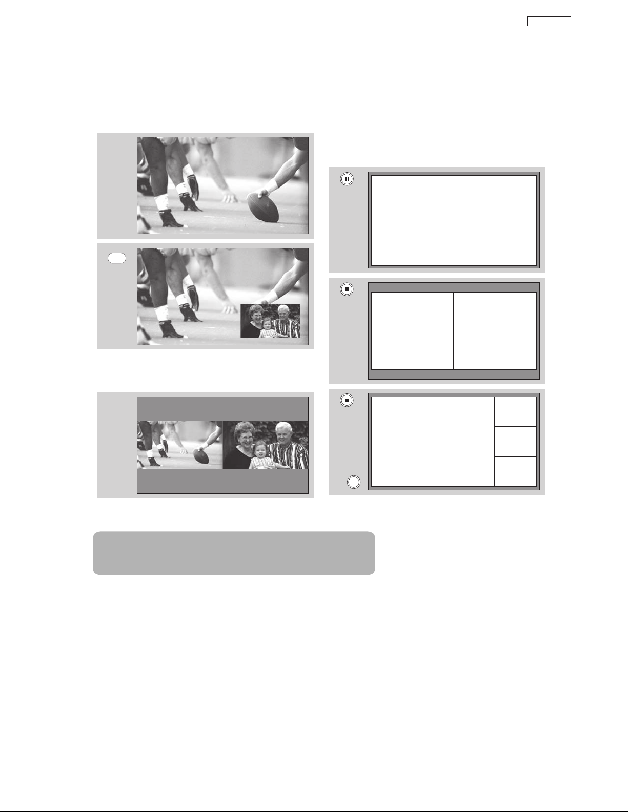
PIP Mode Picture-in-Picture
This feature is only available with a 1080i
signal. To prevent a pattern burn, occasionally
move the sub-picture using the CURSOR
buttons.
SPLIT Mode Picture-in-Picture
Split Mode PIP displays the main picture and subpicture evenly on the screen.
PAUSE button
If you wish to freeze the sub-picture, press the
PAUSE button. This is convenient when trying to
write down the address for a mail order company,
recording statistics for a sporting event, etc. To return
the picture to motion, press the EXIT button. Press
the PAUSE button repeatedly to toggle between
FREEZE modes (Main Freeze, SPLIT and STROBE).
MAIN PICTURE
SUB PICTURE
MAIN PICTURE
SUB PICTURE
Picture-in-Picture (PIP)
PIP
MAIN PICTURE
SUB PICTURE
DP65
Freeze
MAIN PICTURE
SUB PICTURE
EXIT
Note : PIP Specifications in the following pages 26 & 27.
Freeze
Freeze
Freeze
Freeze
24
Page 26

MAIN FREEZE
Press the PAUSE button to freeze one frame of the
picture you are currently viewing and the frozen
frame will show in the Main Picture. Press the EXIT
button to return to normal viewing. This feature is
useful for freezing a picture frame with addresses.
SPLIT FREEZE
Press the PAUSE button to freeze the picture you
are currently viewing (only the right sub-picture will
freeze). Press the EXIT button to return to normal
viewing. Please refer to page 27 for detailed spec.
STROBE FREEZE
Press the PAUSE button to freeze three frames of
the picture you are currently viewing (only the 3
sub-pictures will freeze). Press the EXIT button to
return to normal viewing. This feature is useful for
viewing a moving picture that has many details, for
example, a close play in a sporting event or a golf
swing. Please refer to page 27 for detailed spec.
NOTE: 1. The default FREEZE mode is the MAIN
freeze followed by the SPLIT freeze and
then the STROBE freeze. The last Freeze
mode you selected before you pressed the
EXIT button will be the one that comes up
after pressing the PAUSE button again.
2. Each freeze frame is delayed about 0.1
(1/10) second.
MAIN PICTURE
SUB PICTURE
Picture-in-Picture (PIP)
3. When the input is HDMI signal , the FREEZE
mode is the MAIN picture FREEZE.
DP65
EXIT
MAIN PICTURE
SUB PICTURE
EXIT
EXIT
Note : PIP Specifications in the following pages 26 & 27.
25
Page 27

Picture-in-Picture (PIP)
PIP Specifications
PIPInputMode
Air Cable Input1 Input2 Input3 Input4 Input5Sub Picture
DigitalCH
AnalogCH
YesYes - - YesYesYesYes
YesYes - Yes - YesYesYes
YesYes - YesYes - YesYes
YesYes - YesYesYes - Yes
YesYes - YesYesYesYes -
Main Picture
Air DigitalCH
Cable DigitalCH
Input1 HDMI
Input2S/Video
Input3Ypbpr
Input4Ypbpr
Input5S/Video
AnalogCH
AnalogCH
S/Video
Video
Video
(a)Thereisnocombinationbetweensameinput.
(b)ThereisnocombinationbetweenTVandTV,becauseofonetunersystem.AndthedigitalCHformatisonly480i.
(c)HDMIinputisonlyforMainpicture.
(d)UsercanonlyselectavailablecombinationbyInputMenu.
POPMode
Mode
540p
Sub Pic.
Main Pic.
DigitalCH
(480i)
AnalogCH4x3
1080i16x9
720p16x9
480p16x9/4x3- - - - - - - - - -
480i16x9/4x3YesYesYesYes - - YesYesYesYes
S/Video16x9/4x3YesYesYesYes - - YesYesYesYes
Aspect
16x9/4x3 - - - Yes - - YesYesYesYes
PIPMode:Sub picture 16x9
Mode
1080i 1080i
Yes1:AutoAspectON
Sub Pic.
Main Pic.
Aspect
16x9 Yes - - Yes - - Yes1 - Yes1 -
PIPMode:Sub picture 4x3
Mode
Sub Pic.
Main Pic.
1080i 1080i
Yes2:AutoAspectOFF
Aspect
16x9 - Yes Yes - - - Yes2 Yes Yes2 Yes
DigitalCH
AnalogCH
- - - Yes Yes Yes Yes Yes
- - - Yes Yes Yes Yes Yes
DigitalCH
480i
16x94x34x316x916x916x9
- - - Yes - - YesYesYesYes
- - - - - - - - - -
- - - - - - - - - -
DigitalCH
480i
16x9 4x3 4x3 16x9 16x9 16x9
DigitalCH
480i
16x9 4x3 4x3 16x9 16x9 16x9
HDMI S/Video S/Video Ypbpr
Analog
Analog
Analog
1080i720p480p480iS/VideoScan
CH
4x3
1080i 720p 480p 480i S/VideoScan
CH
4x3
1080i 720p 480p 480i S/VideoScan
CH
4x3
Video
16x94x316x94x3
16x9 4x3 16x9 4x3
16x9 4x3 16x9 4x3
Ypbpr
Video
DP65
S/Video
26
Page 28
Picture-in-Picture (PIP)
PIP Specifications (cont.)
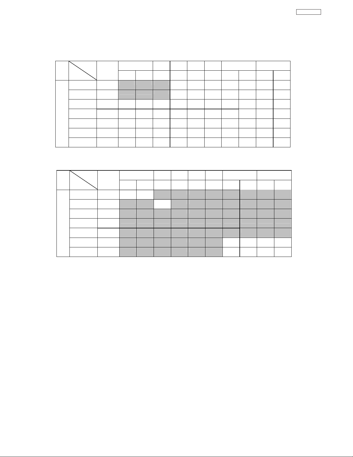
SPLITMode
Sub
Mode
Main
DigitalCH
540p
STROBEMode
Mode
540p
(480i)
AnalogCH 4x3
1080i 16x9Yes Yes Yes Yes Yes Yes Yes Yes Yes Yes
720p 16x9Yes Yes Yes Yes Yes Yes Yes Yes Yes Yes
480p16x9/4x3 Yes Yes Yes Yes Yes Yes Yes Yes Yes Yes
480i
S/Video16x9/4x3 Yes Yes Yes Yes Yes Yes Yes Yes Yes Yes
Main
DigitalCH
(480i)
AnalogCH4x3 - - - - - - - - -
1080i
720p
480p16x9/4x3 - - - - - - - - - -
480i16x9/4x3 - - - - - - Yes Yes Yes Yes
S/Video16x9/4x3 - - - - - - Yes Yes Yes Yes
Aspect
16x9
4x3
16x9/4x3 Yes Yes Yes Yes Yes Yes Yes Yes Yes Yes
Sub
Aspect
16x9
16x9 - - - - - - - - - -
16x9 - - - - - - - - - -
16x9 4x3 4x3 16x9 16x9 16x9
- - Yes Yes Yes Yes Yes Yes Yes
16x9 4x3 4x3 16x9 16x9 16x9
4x3
Yes Yes
DigitalCH
480i
DigitalCH
480i
Analog
--
Analog
1080i 720p 480p 480i S/VideoScan
CH
- Yes Yes Yes Yes Yes Yes Yes
-
1080i 720p 480p 480i S/VideoScan
CH
- - - - - - - -
Yes
16x9 4x316x9 4x3
4x3
16x9 4x3 16x9 4x3
4x3
DP65
27
Page 29

New Software upgrade process
Upgrades
It shows software information and easy upgrade
procedure. This function allows the TV software to be
upgraded by using a flash card (MMC CARD). If a
future software upgrade is required for your TV,
HITACHI will notify and provide you with a flash card.
In order to receive written notification and the flash
card, please complete and return the warranty card.
1. Insert MMC CARD
2. Press the CURSOR buttons
or to highlight
UPGRADE NOW.
3. Press the SELECT button to select and start
upgrading.
4. Unplug the power cord when the upgrade is
complete.
NOTE:
DP65
1. Any power interruption during the upgrade
process will cancel the upgrade. When this
happens, repeat the upgrade procedure.
2. The name of MMC Vxxx.xxxx upgrade
will only appears when a MMC or SD
card is inserted on the back of the TV ;
then it will show the MMC Vxxx.xxxx
file number.
Setup
OR
OR
Magic Focus Tune Up
Menu Preference
Set The Inputs
Set Virtual HD
Set Black Side Panel
Set Closed Captions
Set Audio Out
Upgrades
Move SEL Set
Setup
Upgrades
Software Version # : Main Vxxxx.xxxx
MMC Vxxxx.xxxx
MMC Software Upgrade
Upgrade Now
Please Insert MMC card
before upgrading.
Move SEL Return
28
Page 30

DP65
SERVICE ADJUSTMENTS
TO GO TO AN ADJUSTMENT, CLICK ON ITS HEADING BELOW
1. CHASSIS ADJUSTMENT...................................................................................................................................30
1-1. Service Menu Access ................................................................................................................................................30
1-2. Memory Initialize ....................................................................................................................................30
1-3. Comb Filter Operation Check..............................................................................................................................32
1-4 Video Settings Check .....................................................................................................................32
1-5. High Voltage Adjustment ........................................................................................................................
2. FINAL ASSEMBLY ADJUSTMENT (Adjustment order) ..................................................................................
2-1. Cut Off Adjustment..................................................................................................................................32
2-2. DCU Phase Data Setting ......................................................................................................................33
2-3. Horizontal Position Adjustment (Coarse) ................................................................................................33
2-4. Raster Tilt (Deflection Yoke)....................................................................................................................33
2-5. Beam Alignment......................................................................................................................................34
2-6. Raster Position Adjustment ....................................................................................................................34
2-7. Beam Form Adjustment ..........................................................................................................................35
2-8. Vertical Size, Horizontal Size Adjustment ...........................................................................................35
2-10. Lens Focus..............................................................................................................................................36
2-11. Static Focus ............................................................................................................................................38
2-12. Digital Convergence ..............................................................................................................................38
2-12-1. Magic Focus Character Set Up ..................................................................................................39
2-12-2. Magic Focus Pattern Set Up ......................................................................................................40
2-12-3. Convergence Jig Screen Specification ......................................................................................47
2-12-4. Raster Position Adjustment ........................................................................................................48
2-12-5. Convergence Point Adjustment ..................................................................................................48
2-12-6. Magic Focus Initialize ................................................................................................................49
2-13. Blue Defocus Adjustment........................................................................................................................50
2-14. White Balance Adjustment......................................................................................................................50
2-15. Sub Brightness Adjustment ....................................................................................................................51
2-16. Adjustment OSD Flow Chart ..............................................................................................................................52
2-17. Horizontal Position Adjustment ..............................................................................................................60
2-18. Scanning Area Check ............................................................................................................................60
2-19. Top/Bottom Panel Distortion Check .....................................................................................................61
2-20. Side Panel Distortion Check ..............................................................................................................................61
2-21. I2C Parameter List ..................................................................................................................................63
2-22. Protection Circuit Block Diagram .............................................................................................................82
2-23. Troubleshooting Flow Chart ..................................................................................................................83
32
31
*IMPORTANT
For many of the above adjustments, it is necessary to have an HDTV (1080i or 720P) signal generator, SDTV (480P)
signal generator, as well as the usual NTSC (480i) signal generator.
Hitachi recognizes that few companies offer HDTV or SDTV signal generators and that the cost of these generators is
sometimes prohibitive. For this reason, we suggest the use of a set-top-box for HDTV and SDTV adjustments. Usually,
there is a switch on the set-top-box which enables it to output HDTV (1080i or 720P) or SDTV (480P) signals even with
no input. In this case, the sync is automatically detected by the TV (at the Y-P
29
TABLE OF CONTENTS
Inputs on the rear panel).
BPR
Page 31

DP65
ADJUSTMENT PROCEDURE START-UP
The 51F59/A/J, 57F59/A/J and 65F59/A/J PTV sets
pass through adjustment procedures during the assembly
process. These adjustments must be done to assure the
best performance of the PTV set for the consumer.
Also, after servicing, these same adjustments must be
done. Most of the adjustments are made by the I
2C bus
by changing data in the Adjustment mode menu.
On pages 61-90 shows the complete parameter list
with a brief description, signal format, the adjustment
range and the initial data.
1.1 HOW TO GET TO ADJUSTMENT MODE
Chassis adjustment mode can be access by first press
and keep press the MENU key on the CONTROL PANEL
of the TV, then press the R/C keys MENU+8+SELECT
to enter adjustment mode.
SERVICE
SUB BRIGHT
WHITE BAL HIGH
WHITE BAL MED
WHITE BAL STD
WHITE BAL B/W
H POSITION **
V POSITION **
FACT RESET
Other way to access this mode is by use JIG R/C code: (9C Hex).
To escape from Adjustment Mode press “INPUT” key on Side
panel or EXIT key of R/C to exit service adjustment mode.
1.2 CHANGING DATA AND SELECTING ADJUSTMENT
CODE
When the PTV set is in adjustment mode, the cursor F, E,
G, H and MENU keys of the remote control or front panel
may be used as the adjustment keys.
A. Use any Hitachi remote control when making an
adjustment.
G, H keys are used for selecting adjustment item.
MENU
F, E keys are used for changing data values.
MENU key is used to advance through the adjustment
mode menus and pages.
SELECT
EXIT
EXIT
Remote Control Buttons
Decrease
Data Value
MENU
Control Panel Buttons
SELECT
EXIT
EXIT
Change
Selection (Up)
Increase
Data Value
Change
Selection (Down)
B. After finishing the necessary adjustment press the R/C
EXIT key or EXIT key on the side panel.
Adjustment mode is released and PTV set returns to
normal condition.
2 MEMORY INITIALIZE
2.1 MEMORY INITIALIZE OPERATION
NOTE: The execution of this function returns the
adjustment codes to the preset values, therefore,
adjustment data will be lost.
Procedure 1
(1) Enter Adjustment mode by the method described in
sub-items 1.1 and 1.2 from item 1 (“Adjustment
procedure start up”).
(2) Get to the second page of Adjust Mode by pressing
remote control “Menu” key once, or with either the
R/C or front panel
G, H cursor keys several times.
(3) Select MEMORY INIT adjust code.
(4) Activate MEMORY INIT by pressing
E cursor key for
more than 3 seconds.
(5) Check the following process for initialization opera-
tion.
Procedure 2
(1) Short circuit on PINT connector on the Signal PWB;
so the Initialization process starts as follows.
·Process of Memory Initialize operation.
①
A screen is be colored cyan when MEMORY INIT
start.
A screen is be colored green when MEMORY INIT
②
finish normally.
A screen is be colored RED when MEMORY INIT
③
finish abnormally.
(6) Do not unplug from AC outlet until this operation
is complete and do not perform any key operation
either, after this operation each factory setting and
all adjust mode data should reset to delivery settings
automatically.
(7) After Memory Initialize, it should be unplug AC cord.
Unplug and plug AC cord and then all settings and data
are updated.
(8) When PTV turns ON , it will tune CH03 this is the
complete operation of Memory Initialize process.
BACK TO ADJUSTMENTS
30
CH 11
Page 32

D
A
A
2.0 FINAL ADJUSTMENT ORDER FOR SERVICE
ORDER ADJUSTMENT ITEM ASPECT MODE SIGNAL DCU
DATA
1 CUT OFF 16:9 Standard NTSC Signal
2 PREFOCUS 16:9 Standard Crosshatch
3 DCU PHASE DATA SETTING 16:9 Standard NTSC Signal-DCU
4 HORIZONTAL POSITION
ADJUSTMENT (COARSE)
5 RASTER TILT 16:9 Standard NTSC Signal-DCU CLEAR
6 BEAM ALIGNMENT 16:9 Standard Crosshatch CLEAR
7 RASTER POSITION 16:9 Standard Circle Pattern -DCU CLEAR
8 VERTICAL SIZE ADJUSTMENT 16:9 Standard NTSC Signal-DCU CLEAR
9 HORIZONTAL SIZE ADJUSTMEMT 16:9 Standard NTSC Signal-DCU CLEAR
10 BEAM FORM 4:3 Standard Crosshatch
11 LENS FOCUS ADJUSTMENT 16:9 Standard Crosshatch
12 STATIC FOCUS ADJUSTMENT 16:9 Standard Crosshatch
13 CONVERGENCE ADJUSTMENT BY
Remote Control
14 BLUE DEFOCUS 16:9 Standard Crosshatch
15 WHITE BALANCE ADJUSTMENT 16:9 Standard White Raster
16 SUB BRIGHTNESS ADJUSTMENT 16:9 Standard 7 step gray scale
17 HORIZONTAL POSITION
ADJUSTMENT
18 MAGIC FOCUS INITIALIZE 16:9 Standard NTSC Signal-DCU
Do not use Crosshatch for convergence
djustment if the signal is NTSC progressive mode
16:9 Standard Circle Pattern
1080i circle pattern
1080i circle pattern
16:9 Standard NTSC Signal-DCU
16:9 Standard Circle Pattern
PRE HEAT RUN CONDITION
PRESET EACH VR LOCATION AS FOLLOWS:
BEFORE PRE HEAT-RUN.
(1) SCREEN VR ON FOCUS PACK.
Cut off adjustment should be coarse adjusted
(2) FOCUS VR ON FOCUS PACK.
<PRE SET> clockwise fully.
Focus VR
*PRE HEAT RUN TIME
More than 30 min.
If Current cannot be applied this spec, Pre Heat Run should be applied as long as
possible .
R G B
R G B
Focus VR
DP65
<Focus Pack>
Screen VR
31
BACK TO ADJUSTMENTS
Page 33

DP65
DEFLECTION PWB.
RH17
High Voltage Adjustment VR.
TH01
(FBT)
Adjustment Preparation:
1. Allow 20 minutes pre-heat run.
2. Set video conditions to factory presets.
Adjustment Procedure:
1. Access the I2C Adjustment Mode
1.1 Press the following buttons on the remote, in
sequence: MENU, MENU, 8, SELECT.
2. Select SERVICE from adjustment menu by
pressing the button on the remote. This will
collapse the vertical deflection.
3. Turn all screen (G2) controls to the full counterclockwise position.
CH 8
1.3 Comb filter operation check
Adjustment preparation
(1) Receive the color bar signal at the regular tuning
point.
(2) Set the CONTRAST control to MAX and the other
controls to center.
Adjustment procedure
(1) Check line dots condition at border of each color A, B
as follows.
A A
A
B
Check and line dots.
A
B
3D Y/C
Dots
A None
Important: High Voltage adjustment should
!
NOT be adjusted in field. This is
adjusted at factory using precise
loads and should NOT be
readjusted.
1.5 High Voltage Adjustment (should NOT be
readjusted in field).
Adjustment preparation
(1) Connect High Voltage meter to FBT High Voltage
output. Connect GND of High Voltage meter to CPT
GND or FBT GND.
(2) Check that High Voltage adjustment VR (RH17) is
set to mechanical center. (located behind FBT on
DEFLECTION PWB).
(3) Receive circle pattern signal.
(4) VIDEO control should be reset.
Adjustment procedure
(1) Adjust High Voltage to following spec. by turning VR
RH17 slowly. ADJ. SPEC = 31.7KV±0.2kV.
(2) After adjustment, fix VR RH17 with Silicone glue
(KE40RTV).
B None
1.4 Video Settings Check
1.4.1 Color Temperature Control Check
Adjustment preparation
(1) Receive the white raster signal.
(2) Set the video controls to normal conditions.
Adjustment procedure
(1) Select the Video mode using the GH buttons and
press Select button.
(2) Select Color Temperature option using the
buttons and press Select button.
(3) Select MEDIUM using
turn reddish slightly.
(4) Select STANDARD using
will turn more reddish.
(5) Select Black & White using
will turn more and more reddish.
(6) Select HIGH using
bluish.
FE buttons and Picture will
FE buttons and Picture
FE buttons and Picture
FE buttons and Picture will turn
GH
2. FINAL ASSEMBLY ADJUSTMENT
2.1 Cut Off Adjustment
Adjustment preparation
(1) Adjust screen VR’s on Focus Pack fully
counterclockwise.
(2) Adjust Focus VR’s on Focus Pack fully
clockwise.
(3) Set video conditions to factory preset.
(4) The vertical incident illumination on the screen
should be 20 lux or less (room should be dark).
(5) Pre-heat run time should be at least 20 min.
BACK TO ADJUSTMENTS
FOCUS PACK
32
Page 34

Adjustment procedure
49
CH 8
4. Bring up each screen G2 control, one at a time,
until that color is just barely visible. (Also, adjust the
focus control for each color to obtain optimum
focus.)
5. After all colors are finished, press the button
on the remote to un-collapse the vertical, and return
to normal.
NOTE: Never power off the TV while in the Service
position of the I2C Adjustment Mode (vertical
collapsed) as CRT damage may result.
CH 5
CH 9
(1)
Press the MENU key on the CONTROL PANEL of
the TV, then press the R/C keys MENU+8+SELECT
to enter adjustment mode.
(2) Choose “SERVICE” item from I
menu by pressing THUMB STICK E.
(3) Screen VR should be turned clockwise gradually
and set so that retrace line begins to appear.
(4) Return to “NORMAL” mode by THUMB STICK
F again.
(5) Adjust Focus VR’s so that focus is even all
around screen.
2.2 Digital Convergence (DC) Phase Data Setting
Adjustment preparation
(1) Cut off adjustment should be finished.
(2) Set video conditions to factory preset.
(3)R/C must be in DCAM mode (see page 47 ).
Adjustment procedure
(1) Receive any NTSC signal.
(2) Push “SERVICE ONLY” SW (SC01) on SIGNAL
PWB. (Enter to DC ADJ. mode).
(3) Press [ ] key on R/C. (Green cross hatch
is displayed).
Then push EXIT key on R/C. (Character pattern
is displayed. This is the PHASE setting mode).
(4) Set PH-H phase data as shown below by using
[4] and [6] key on R/C.
(5) Set PH-V phase data as shown below by using
[2] and [5] key on R/C.
(6) Set CR-H phase data as shown below by using
CURSOR PAD
F and E key on R/C.
(7) Set CR-V phase data as shown below by using
CURSOR PAD G and H key on R/C.
(8) Push [ ] key on R/C to exit from the
PHASE mode.
(9) Press ASPECT key 2 times on R/C to write the
phase data to memory.
(10) When Green dots are displayed, push [MUTE]
key to return to DC ADJ. mode.
(11) Push “SERVICE ONLY” SW to return to RF or
VIDEO mode.
Normal Mode
PHASE MODE: N
PH-H: F2
PH-V: 07
CR-H: 37
CR-V: 14
2.3 Horizontal Position Adjustment (Coarse)
Adjustment preparation
(1) DC PHASE DATA SETTING should be
finished.
BACK TO ADJUSTMENTS
2C adjustment
Adjustment procedure
(1) Receive circle pattern.
(2) Push SERVICE ONLY switch to display DC
crosshatch. Mark the DC crosshatch center
position using your finger tip.
(3) Push SERVICE ONLY switch again to exit from
the DC crosshatch.
2
(4) Go to I
C ADJ. mode.
(5) Choose H. POSI item by using up/down
cursor key. Adjust horizontal position to match
the circle center to DC crosshatch center
(marked by your finger tip).
2
(6) Exit from I
DC crosshatch
C menu.
ATSC or NTSC
Circle pattern
Circle centerDC crosshatch center
Remark The “SERVICE ONLY” switch located on
the SIGNAL PWB (SC01).
1080i 16:9 STANDARD
(7) Receive any 1080i Signal (fH=33.75KHz) circle
pattern signal (Input to component video
terminal).
(8) Repeat steps (2)~(5).
(9) Press SELECT key, then H. POS H will appear.
It means HD mode is activated.
(10)Exit from I
2
C menu.
2.4 Raster Tilt adjustment (Deflection yoke)
Adjustment preparation
(1) The set can face east or west.
(2) Input the single cross test signal.
(3) Set CONTRAST to MAX, other controls to
CENTER.
(4) The lens focus and horizontal position
adjustment should have been coarse adjusted.
(5) The electrical focus should have been coarse
adjusted.
(6) The digital convergence RAM should be cleared
(uncorrected state). With the TV set off, press
and hold the “SERVICE ONLY” switch and then
press the power button.
(7) Start adjustment 20 minutes or more after TV is
turned on.
Adjustment procedure
(1) Short-circuit 2p EH (TS) sub-mini connectors on
Red and Blue CPT P.W.B.s to project only the
Green beam.
(2) Turn the G deflection yoke and adjust the
vertical raster inclination.
(3) Then, remove the shorted wire on the 2p EH(TS)
sub-mini connectors on the R or B CPT PWB
and project red or blue light and green light
together on screen.
33
DP65
Page 35

DP65
(4) Turn the deflection yoke of R or B and set so that the
inclination of R or B light with respect to the green
light is as shown below on the top and bottom sides.
(5) After raster inclination adjustment, the DY screw
should be screwed to 10-14kg-cm torque.
1
2
, 2≤±2mm
1
≤ ±2 mm
CROSSHATCH (GREEN)
Notes: (1) If internal cross-hatch does not appear after
clearing RAM data, press service switch
again, on DEF./CONV. PWB.
(2) To restore old RAM data, turn TV off and on.
2.5 Beam alignment
Adjustment preparation
(1) Adjust at least 30 minutes after turning on power
switch.
(2) Raster tilt should be completed. Raster position,
horizontal and vertical size, and optical focus
adjustment should be coarse adjusted.
(3) Set video conditions to factory preset.
(4) Receive cross-hatch signal.
2.6 Raster position adjustment
Adjustment preparation
(1) The set can face east or west.
(2) Input the single cross test signal.
(3) Set video conditions to factory preset.
(4) The electrical focus should have been coarse
adjusted.
(5) The digital convergence RAM should be cleared
(uncorrected state). With the TV set off, press
and hold the service switch located on the
SIGNAL PWB and then press the power
button.
(6) Start adjustment 20 minutes or more after TV is
turned on.
Adjustment procedure
(1) Turn the centering magnets for red, green, and
blue to satisfy the condition below. The red and
blue horizontal lines should match with green.
(RED) (BLUE)
1
51” 20 25
57” 20 25
Tolerance: ± 2mm
2
Units = millimeters
25.4mm = 1in.
R
B
Adjustment procedure
(1) Green (G) tube beam alignment adjustment.
Short-circuit TS (2p EH) subminiature connector
plug pins of Red (R) and Blue (B) on the CPT
boards and project only Green (G) light or you
may cover the R and B lens.
(2) Put Green (G) tube beam alignment magnet to
the cancel state as shown below.
(3) Turn the Green (G) electrical focus (Focus Pack)
counterclockwise all the way and make sure of
position of cross-hatch center on screen. (Halo
state.)
(4) Turn the Green (G) electrical focus (Focus Pack)
clockwise all the way. (Blooming state.)
(5) Turn two magnets forming alignment magnet in
any desired direction and move cross-hatch
center to position found in (3).
(6) If image position does not shift when Green (G)
static focus (Focus Pack) is turned. Green (G)
beam alignment has been completed.
(7) If image position shifts when Green (G) static
focus (Focus Pack) is turned, repeat (2)-(6).
(8) Conduct beam alignment for red (R) and
Blue (B) focus: Focus Pack UFPK.
(9) Upon completion of adjustment, fix beam
alignment magnets with white paint.
BACK TO ADJUSTMENTS
Geometric
center of the
G
12
screen
(2) Upon completion of adjustment, fix centering
magnets with white paint.
NOTES: (1) If internal cross-hatch does not appear
after clearing RAM data, press service
switch again.
(2) To restore old RAM data, turn TV off and
on.
34
Page 36

2.7 Beam form adjustment
Adjustment preparation
(1) Raster Position should have been completed.
(2) The raster tilt and centering should have been
completed.
(3) Set video conditions to factory preset.
(4) Input the dot signal.
(5) Set Aspect to 4:3 Standard Mode.
Adjustment procedure
(1) Green PRT beam shape adjustment. Short-
circuit TS (2p EH) sub-mini connectors on Red
and Blue CPT P.W.B.s to project only the Green
beam.
(2) Turn the green static focus VR, on the Focus
Pack, fully clockwise. (Blooming)
(3) Make the dot at the screen center a true circle
using the 4-pole magnet as shown below.
(4) Also adjust the Red and Blue PRT beam shapes
according to the steps (1) to (3).
(5) After the adjustment has been completed, return
R, G and B static VRs to the just focus point.
(6) After the BEAM FORM is completed, fix the
BEAM FORM magnet with white paint.
PRT SURFACE SIDE
4-POLE BEAM
SHAPE CORRECTION
ZERO FIELD
SPACER (NO
ADJUSTMENT)
TRUE CIRCLE SPECIFICATION
2-POLE BEAM
ALIGNMENT
MAGNET
b
a
TRUE CIRCLE DEGREE: a/b
SPECIFICATION: 1.0-1.1
2.8 HORIZONTAL SIZE ADJUSTMENT
ADJUSTMENT
Adjustment preparation
(1) Receive any NTSC signal.
(2) VIDEO control should be set Factory Preset
condition.
(3) BEAM FORM adjustment should be finished.
(4) The Convergence should not be corrected.
Adjustment procedure
(1) Press Service Only button on the SIGNAL PWB
then press the [MUTE] key on R/C at the same
time. Uncorrected crosshatch is displayed.
(2
) Adjust H size as follows , using R711 (Horizon-
tal Size VR).
BACK TO ADJUSTMENTS
MAGNET
(3) After adjustment press the "SERVICE ONLY" SW
to exit from the Digital Convergence crosshatch.
H. Size
Specification
51” 1070
57” 1195
65” 1365
Tolerance:+/-5mm unit : mm
Left end of Green color
vertical line.
VERTICAL SIZE ADJUSTMENT
2.9
Adjustment preparation
Green DCU crosshatch (with conv. Data is clear)
Right end of Green color
vertical line.
Between the vertical lines at the left and right end.
(1) Receive any NTSC signal.
(2) VIDEO control should be set Factory Preset
condition.
(3) Horizontal Size adjustment should be finished.
(4) The Convergence should not be corrected.
Adjustment procedure
(1) Press Service Only button on the SIGNAL PWB
then press the [MUTE] key on R/C at the same
time. Uncorrected crosshatch is displayed.
(2) Adjust V size as follows , using R607 (Vertical
Size VR).
(3) After adjustment press the "SERVICE ONLY" SW
to exit from the Digital Convergence crosshatch.
V. Size
Specification
51” 560
57” 625
Tolerance:+/-5mm
unit : mm
Green DCU crosshatch
65” 710
(With Conv. data cleared.)
Center line
35
DP65
L=
Top end of Green color horizontal line.
L=
Bottom end
of Green color horizontal line.
between the horizontal
line at the top and
bottom
Page 37

Change of Color Aberration
Short focus Long focus
RED LENS Orange Scarlet
GREEN LENS Blue Red
BLUE LENS Purple Green
DP65
2.10 LENS FOCUS ADJUSTMENT
Adjustment preparation
(1) The orientation of PTV set is arbitrary, west,
east, north and south.
(2) Centering DY inclination should have been
adjusted.
(3) Static focus adjustment should have been
coarse adjusted.
(4) Drive VR location adjustment should have been
completed. (Red : 12 O’clock, Green : 1~2
O’clock).
(5) Receive the cross-hatch pattern signal.
(6) Refer to setup below.
CONTRAST : HALF of full scale.
BRIGHTNESS : minimum
Adjustment procedure
(1) Loosen the fixing screw or wing nut on the lens
cylinder so that the lens cylinder can be turned.
(Be careful not to loosen too much). After
completing steps (4), (5), (6) below, tighten the
fixing screws or wing nuts for each lens with a
torque of 1.18N.m (12Kgf cm) ~ 1.67N.m (17Kgf
cm).
(Be careful the lens cylinder does not turn after
having tightened the screw or wing nuts. If it is
tightened too much, lens may tilt or screw may
break.)
Lens Assy
Lens Assy
(2) Apply covers to each color of R, G and B lenses.
And project a single color on the screen and
adjust in sequence. (The adjustment order of G,
R and B is only an example.)
(3) If the lens adjustment knob is turned clockwise
viewed from the front, the color Aberration
change as follows.
Cross-Hatch
Color
Aberration
(4) In case of G lens. Set to the point where the
chromatic aberration switches from blue to red.
If the chromatic aberration appearing all over
the screen is not the same, observe the vertical
bright line and adjust lens focus as specified in
table below. When the red chromatic aberration
appearing at both sides of the bright line is not
equal, observe the side with larger chromatic
aberration when adjusting.
(NOTE 1)
Fixing Screw
(NOTE 2)
Fixing Wing Nut
TYPE 1 TYPE 2
L1
L2
I
O
BACK TO ADJUSTMENTS
36
Page 38

CHASSIS DP65/DP65G
SCREEN SIZE 51”(D250) 57”(D250)
L1 and L2
(PITCHES from CENTER) 3.0 2.0
BETWEEN
L1&L2 * **
COLOR
* **
ABERRATION I 3.0mm MAX 3.0mm MAX
* **
O 3.0mm MAX 3.0mm MAX
(NOTE) * Slightly reddish or no color
** Slightly bluish or no color
65”(D260)
2.0
*
**
2
.0mm MAX
**
2
.0mm MAX
CHASSIS DP65/DP65G
SCREEN SIZE 51”(D250) 57”(D250)
L1 and L2
(PITCHES from CENTER) 5.0 5.0
BETWEEN
L1&L2 * **
COLOR * **
ABERRATION I 3.5mm MAX 2.0mm MAX
** *
O 2.5
mm MAX 2.0mm MAX
(NOTE) * Slightly reddish or no color
** Slightly crimson or no color
65”(D260)
4.0
*
*
2
.0mm MAX
*
2
.0mm MAX
DP65
OPTICAL FOCUSING ADJUSTMENT GREEN
Change the signal to the circle pattern and fine
adjust. Observe the corner part of the screen,
especially observe number in the small circle
when adjusting. If the focus performance at the
screen center exceeds the lower limit, it is
acceptable.
(5) In case of R lens. Set the position where the
chromatic aberration changes from red to
crimson. As shown below, observe the vertical
bright line and adjust lens focus where the
crimson or red chromatic aberration slightly
appears inside, and crimson or red outside
(reference value : 1~3mm) at the point specified
in table below. Change the signal and fineadjust the same way as the G lens.
L
I
O
NOTE: Setting the center between Red and crimson
is optimum.
OPTICAL FOCUSING ADJUSTMENT RED
Small circle of circle pattern
NOTES: 1. Since the G light is very important for
picture quality and performance, pay
special attention in its adjustment.
2. Be careful not to touch the lens with your
fingers when adjusting.
(6) In case of B lens. Set the position where the
chromatic aberration changes from purple to
green. As shown below, observe the vertical
bright line and adjust lens focus where the
purple or green chromatic aberration slightly
appears inside and purple or green outside
(reference value : 1~3mm) at the point specified
in table below. Change the signal and fineadjust in the same way as the G lens.
L
I
O
NOTE: Setting to the center between purple and
crimson is optimum.
37
Page 39

DP65
CH 10
OPTICAL FOCUSING ADJUSTMENT BLUE
CHASSIS DP65/DP65G
SCREEN SIZE 51”(D250) 57”(D250)
L1 and L2
(PITCHES from CENTER) 5.0 5.0
COLOR ** **
ABERRATION I 3.5mm MAX 4.0mm MAX
(NOTE) * Slightly purplish or no color
BETWEEN
L1&L2 * **
* *
O 3.5mm MAX 4.0mm MAX
** Slightly greenish or no color
3.0mm MAX
3.0mm MAX
(7) After all colors have been adjusted, display all
colors with the cross-hatch pattern signal and
check the focus performance.
(8) Then, select the circle pattern signal and check
the focus performance of each color and all
colors together.
(9) If the focus performance is not acceptable re-
adjust step (1) to (6).
2.11 STATIC FOCUS ADJUSTMENT
Adjustment preparation
(1) LENS FOCUS adjustment should be finished.
(2) Contrast : MAX
Brightness : Center.
(3) Receive the 480i/480p circle pattern signal &
1080i circle pattern.
(4) Apply covers to the lens of the colors you are
not adjusting and project only one color on the
screen.
Adjustment procedure
(1) Red and blue static focus adjustment. Adjust
the static focus VR on Focus pack (UFPK) so
that the center of circle pattern is the most clear.
Check that the focus does not get conspicuously
worse at the edges of the circle pattern signal or
cross-hatch signal.
(2) Green static focus adjustment. Adjust the static
focus VR on Focus pack (UFPK) (for green) so
that the center of circle pattern is the most clear.
Check that the focus does not get conspicuously
worse at the checking point, the periphery of
circle pattern cross-hatch signal.
65”(D260)
4.0
*
*
*
2.12 Digital convergence adjustment
Note: 1. If replacing a PRT, DY, etc. perform auto-
digital convergence first. (Press front panel
MAGIC FOCUS switch). This can eliminate
the need for a complete digital convergence
alignment.
2. To enter digital convergence adjustment
mode without removing the front speaker
TO SET REMOTE TO DCAM (ADJUST MODE):
grill, please do the following:
1) Press and hold the [TV] button on remote.
1) Press and hold [TV] key on the R/C then
2) Press and release the [MENU] button.
press [ASPECT]+[9] keys in sequence.
3) Press and release the [INFO] button.
2) At this moment the R/C is in LINE Adjust
4) Release the [TV] button.
MODE.
3) Press [STOP] key to enter Dynamic Adj.
MODE , to adjust Digital Conv. change the
TO RETURN REMOTE TO NORMAL:
R/C to DCU mode as explain in page 45.
1) Press and hold the [TV] button on remote.
4) Proceed with convergence adjustment
2) Press and release the [0] button.
and save the data.
3) Press and release the [1] button.
5) Do MAGIC FOCUS sensor initialization.
6) To exit, press [PLAY]+[EXIT] keys on the
4) Release the [TV] button.
R/C in order to exit Dynamic Adj Mode.
Adjustment preparation
(1) Receive an RF or video signal.
(2) Set controls to factory preset.
(3) Install jig screen on the set.
(4) Note the center of the video pattern displayed.
This is necessary to match dotted lines
(adjustment point viewed) and actual point that
is adjusted and displayed by the video signal.
(5) Press the service only switch (on SIGNAL
PWB). The pattern displayed is now the digital
convergence mode.
(6) When performing a complete digital
convergence adjustment CLEAR DATA in RAM.
(With the TV set off, press and hold the service
switch located on the SIGNAL P.W.B. and
then press the POWER button).
NOTE: Checking point for the periphery of picture.
Adjustment Point
Checking point
38
BACK TO ADJUSTMENTS
Page 40

DP65
Parameter Normal
ADJ. DISP 0F
DEMO WAIT 00
INT. START 13
V. SQUEEZE 10
INT STEP 1 02
INT STEP 2 06
INT BAR 2D
INT DELAY 01
MGF STEP 1 50
MGF STEP 2 06
MGF BAR 1B
MGF DELAY 01
SEL. STAT. 00
LINE WID 7F
ADD LINE 09
SENSOR CK 00
PORT 0 07
PORT 1 06
PORT 2 05
PORT 3 04
PORT 4 03
PORT 5 02
PORT 6 01
PORT 7 00
AD LEVEL 03
CENT. BAL 01
E. DISPLAY 00
ADJ. TIMS 60
AD LEVEL 05
AD NOISE 0A
OVER. LF-H 01
OVER. LF-V 00
OVER. RI-H 00
OVER. RI-V 00
PHASE MOT 50
H. BLK-RV 0A
H. BLK-GV 03
H. BLK-BV 09
H. BLK-H 20
PON DELAY 0F
IR-CODE 00
INITIAL 50 9E
MGF 50 96
CENTER 50 FE
STAT 50 FE
DYNA 50 9F
ADJ. PARAMETER
ADJ. DISP.: 0F
DEMO WAIT: 1F
INT. START: 13
V. SQUEEZE: 10
49
CH 5
2.12.1 MAGIC FOCUS Character Set-Up
This instruction should be applied when a new
Signal Block or complete chassis is being replaced.
Adjustment Preparation
(1) Receive NTSC RF or video signal.
(2) With Power off, PRESS and HOLD the SERVICE
ONLY button on SIGNAL PWB, then press the
Power On/Off, when picture appears release
SERVICE ONLY switch (Internal crosshatch is
displayed without conv. correction data).
(3) Set R/C to DCAM mode (refer to page 45).
(4) Press the DAY/NIGHTbutton 2 times for ROM READ
operation. Picture will appear with convergence
correction data.
Adjustment Procedure
(1) Press key on R/C. (One additional line appears
near the top and near the bottom.)
(2) Press key, then ADJ. PARAMETER mode is
displayed as following.
(3) Press CURSOR PAD
DISP. data.
(4) Press CURSOR PAD H to access DC parameter.
Change the data as shown on Table 1, DC
Parameter.
(5) Press Aspect key 2 times to write changed data into
EEPROM. (First press ADJ. PARAMETER/ROM
WRITE? is displayed for alarm. 2nd press, writes
data into EEPROM. Green dots appear after
completion of operation.)
(6) Press MUTE key 3 times to exit from ADJ.
PARAMETER mode.
F or E to change the ADJ.
BACK TO ADJUSTMENTS
TABLE 1. - Digital Convergence PARAMETER
39
Page 41

RH : 04
RV : FF
1
2
3
4
5
6
7
0
1
3
5
7
01234567
RH 04 00 fa 00 fa 00 04 fe
RV ff fe 01 00 fe 01 00 00
GH 04 00 fc 02 fc 00 04 fe
GV ff fe ff 00 ff 01 00 00
BH 06 00 fc 02 fc 00 06 00
BV ff fe ff 00 00 01 ff 00
Pattern Position
Adj. Mode
0
2
4
6
Pattern: 51” & 57” (Sensor: 20mm)
2.12.2 MAGIC FOCUS Pattern Set-Up
49
CH 5
NOTE: (1) This instruction should be applied when a new
Signal Block or complete chassis is being replaced.
(2) This instruction shows how to set up the pattern
position for MAGIC FOCUS.
Adjustment Preparation
(1) Receive NTSC RF or video signal.
(2) With Power off, PRESS and HOLD the SERVICE
ONLY button on SIGNAL PWB, then press the
Power On/Off, when picture appears release
SERVICE ONLY button (Internal crosshatch is
displayed without conv. correction data).
(3) Set R/C to DCAM mode (refer to page 45).
Adjustment Procedure
(1) Press key on R/C. (One addtional line appears
near the top and near the bottom.)
(2) Press Forward key, then MAGIC FOCUS PATTERN
mode is displayed as follows:
(3) Use [6] key on remote control to rotate the arrow.
Arrow indicates each sensor position. (Upper left
corner, middle top, upper right corner, right middle, in
this order).
(4) Use the keys to switch color of pattern.
INFO : Green pattern
0 : Red pattern
INPUTS : Blue pattern
(5) Press CURSOR PAD
F or E to change the data
value to the horizontal direction. Press CURSOR
G or H to change the data value to the vertical
PAD
direction.
(6) Set the data as shown below:
DP65
(7) Press ASPECTkey 2 times to write the changed data
in EEPROM. (First press, ROM WRITE ? 2nd press,
writes data into EEPROM. Green dots appear after
completion of operation.)
(8) Push POWER key (on control panel) to exit from
PATTERN mode.
BACK TO ADJUSTMENTS
40
Page 42

DP65
* Explanation of "Conv. For Outside Signal"
function
a) Press "Service Only SW" on SIGNAL PWB,
then display "Normal Crosshatch". (Fig.11)
Marker (Adjustment point)
b) Press [MENU] key on R/C,
then display "Red + Green Crosshatch with Red
Marker" or "Green Crosshatch with Green Marker"
or "Blue + Green Crosshatch with Blue Marker".
(Fig.12)
c) Press [MENU] key on R/C again,
then display "Normal Crosshatch on Main Picture"
Fig. 11
Marker
(Fig.13)
d) Press [MENU] key on R/C again,
then display "Cross Marker + Box Marker on Main
Picture". (Fig.14)
e) Press [MENU] key on R/C again,
then display "only Box Marker on Main Picture".
(Fig.15)
Fig. 12
Marker
f) Press [MENU] key on R/C again,
then display "Normal Crosshatch" again. (Fig.11)
And repeat procedure 2) ~ 6) by each press
[MENU] key on R/C.
Fig. 13
Marker
Marker
Fig. 14
Fig. 15
41
Page 43

DP65
MAGIC FOCUS OPERATION CHECK
Adjustment preparation
(1) MAGIC FOCUS INITIALIZE OPERATION should be completed.
(2) Receive any NTSC signal.
Adjustment procedure
(1) OPERATION CHECK
MAGIS FOCUS OPERATION
START
*GOOD (Several windows)
PUSH “MAGIC FOCUS”
BUTTON
MAGIC FOCUS
OPERATION
Retry MAGIC FOCUS
INITIALIZE
STOP MAGIC FOCUS
OPERATION by
PUSH MAGIC FOCUS
BUTTON
FINISH
Note:
If there is an error, error code (green) appears for about 1 second in bottom
right corner.
Refer to CONVERGENCE ERRORS next page .
GOOD
NO GOOD
REJECT
MAGIC FOCUS
* NO GOOD (9 cross)
DP6X
42
Page 44

Convergence Errors.
49
CH 5
If an error message or code appears while performing MAGIC FOCUS or initialize (ASPECT , key in DCU
service mode) follow this confirmation and repair method.
1. Turn on power and receive any signal.
2. Press service switch on SIGNAL PWB.
3. Set R/C to DCAM mode (refer to page 49).
4. Press “DAY/NIGHT” then key on remote control.
5. Error code will be displayed in bottom right corner of screen. If there is no error, an “INITIAL OK” message will
appear on screen or green dots will also appear.
Error message
ERROR!!
Error code
CONNECT 1!
DP65
X
6. Follow repair table for errors.
DCU REPAIR TABLE
Error
Code
1
2 Connect 1 1. Darken Outside Light
*2 2. Placing of sensor
3*2
4 Over Flow 1. Check the placement of sensor
5
7
9
10
Error
Display
Code
VF Error Repiar Digital Convergence circuit
3. Is pattern hitting sensor
4. Check connection and solder bridge of sensor
5. Replace sensor
6. Replace sensor P.W.B.
7. Sensor Connector check
8. Repair Digital Convergence circuit.
9. Adjustment check (H/V size, centering)
A/D Level Same as Error Code 2
2. Adjustment check (H/V size, centering)
3. Conv. amp. gain check *1 (check resistor values only)
Convergence Same as Error Code 4
Operation Same as Error Code 4
Connect 2 Same as Error Code 2
Noise Input strong field signal
Check the wiring of connector between sensor and Signal PWB
Countermeasure
No. 1 3
Sensor position
Application
Initialize
X
X
XX
XX
XX
XX
X X
Magic
Focus
X
X
11
*1 -- RK 53, 54, 57, 58, 61, 62, 65, 66, 69, 70, 73 and 74 check these resistors.
*2 Sensor Position
Sync Input strong field signal
Check the wiring of connector between sensor and Signal PWB
0 1 2
73
654
8 Sensors
43
(View from front side)
XX
Page 45

DP65
Digital Convergence Repair Info. Check Adjustment Pattern
Confirm of appearance of DCU Crosshatch in DCU Adjustment Mode, by pushing of Service
Only SW (SCOI).
Procedure
1) Push Service Only SW (SC01) on SIGNAL PWB.
2) If DCU Crosshatch (corrected almost well) is displayed, Status is OK.
3) DCU Crosshatch is not displayed, Uneven Crosshatch or No Correction Crosshatch is
displayed, DCU circuit has any defects.
Counter Measure for Trouble
if DCU Crosshatch is not displayed (External Video Signal is continuously displayed),
check next items.
1) Assembly Error of DCU uCOM (IS07), X'tal (XS01), Reset 1C (IS05), or other peripheral
parts
2) Solder-Bridge of DCU uCOM (IS07) 7-13pin
3) Solder-Bridge of Reset 1C (IS05)
4) Solder-Bridge of PCJG connector
5) "Ys" signal line {from DCU LSI (IS06) 53pin to RGB processor (IX01) 2pin)
6) "Busy" signal line (from DCU uCOM (ISO?) 66pin to SUB uCOM (I001) 95pin)
7) "Reset" signal line (from Reset 1C (IS05) 4pin to DCU uCOM (IS07) 7pin)
8) +5V Power supply line (from PDT3 connector 10/11 pin to DCU uCOM (IS07))
If DCU Crosshatch is not displayed (External Video Signal is Muted), check next items.
1) Assembly Error of DCU LSI (IS06), +3.3V Regulator (IS04), or other peripheral parts
2) Solder-Bridge of DCU uCOM (IS07) 36, 72-73pin
3) Solder-Bridge of DCU LSI (IS06) 5, 7,14, 22-25, 29-31, 33-35, 38-39, 48-50pin
4) "Ys" signal line (from DCU LSI (IS06) 53pin to RGB processor (IX01) 2pin)
5) "DCU OSD" signal line (from DCU LSI (ISOG) 48/49/50pin to RGB processor (IX01)
24/25/26pin
6) "Busy" signal line (from DCU uCOM (IS 0 7) 6 6pi n to S UB uC OM ( I 00 1) 9 5 pin)
7) "H.BLK/V.BLK" signal line (from PDT2 connector 7/11 pin to DCU LSI (IS06) 33/35pin
8) PLL of DCU LSI (RS65/67, CS32)
9) +5V Power supply line (from PDT3 connector 1 0 /11 pin to DCU LSI (IS06))
10) +3.3V Power supply line (from +3.3V Regulator (IS04) 4pin to DCU LSI (IS06))
44
Page 46

DP65
If Position Shifted Crosshatch (as show Figure 2) is displayed, check next items.
1) Check DCU Phase Data
Figure 2
If uneven Crosshatch (as show Figure 3) is displayed, check next items.
1) Assembly Error of DCU uCOM (IS07), EEPROM (IS01, ISOS**1), DCU LSI (IS06), DAC
PDT4 connector, or other peripheral par ts
2) Solder-Bridge of DCU uCOM (IS07) 1-2,17-24, 27-32, 42-49, 51-55, 75-80pin
3) Solder-Bridge of EEPROM (IS01, IS03r1)
Example Image of Position Shifted DCU Crosshatch
(IT01),
4) Solder-Bridge of DCU LSI (IS06) 5, 7, 14, 20-2 5, 33-35, 38-39, 48-50, 52, 60, 64, 79, 84,
103,110-111,118-125,128-142pin
5) Solder-Bridge of DAC (IT01) 1- 5, 8-9, 12-13,16-17, 32-33, 36-37, 40-41, 46~8pin
6) Solder-Bridge of PDT4 connector
7) "H.BLK/V.BLK" signal line (from PDT2 connector 7/11 pin to DCU LSI (IS06) 33/35pin
8) PLL of DCU LSI (RS65/67, CS32)'
9) +5V Power supply line (from PDT3 connector 10/11 pin to DCU LSI (IS06))
10) +3.3V Power supply line (from +3.3V Regulator (IS04) 4pin to DCU LSI (IS06))
88,
Note)
Figure 3
Example Image of uneven DCU Crosshatch
*1 : IS03 (EEPROM) is only use by DP5M chassis.
45
Page 47

DP65
If No Correction Crosshatch (All channels, as show Figure 4) is displayed, check
next items.
1) Assembly Error of Reset 1C (IS05), DCU LSI (IS06), DAC (IT01), or other peripheral parts
2) Solder-Bridge of DCU LSI (IS06) 5, 7,14, 20-25, 27-29, 33-35, 44,52, 88pin
3) Solder-Bridge of DAC (IT01) 4-5, 45pin
4) "Mute" signal line (from QC17-C to DAC (IT01) 45pin)
5) +5V Power supply line (from PDT3 connector 10/11 pin to DAC (IT01))
Figure 4
If No Correction Crosshatch (Only one or two channels) is displayed, check next items.
Example Image of No Correction DCU Crosshatch
1) Assembly Error of DCU LSI (IS06), DAC (IT01), Op-Amp (IT02-07), PDT4 connector, or other
peripheral parts
2) Solder-Bridge of DCU LSI (IS06) 60, 64, 79, 84, 98,103pin
3) Solder-Bridge of DAC (IT01) 1-3, 8-9,12-13,16-17, 32-33, 36~37, 40-41, 46~8pin
4) Solder-Bridge of Op-Amp (IT02~07)
5) Solder-Bridge of PDT4 connector
6) "Correction Data (Digital)" signal line (from DCU LSI (IS06) 60, 64, 79, 84, 98, 103pin to
DAC(IT01) 1-3, 46-48pin)
7) "Correction Data (Analog)" signal line (from DAC (IT01) 8/12/16/33/37/41 pin to PDT4 connector)
8) +5V Power supply line (from PDT3 connector 10/11 pin to Op-Amp (IT02-07))
9) -5V Power supply line (from PDT3 connector 5-6pin to Op-Amp (IT02-07))
46
Page 48

19.7 90.8 90.8 90.8 90.8 90.8 90.8 90.8 90.8 90.8 90.8 90.8 90.8 19.7
30.5
41.0
30.5
41.0
82.0
82.0
82.0
82.0
82.0
82.0
1129
635
51F7 (Part Number H312272)
22 101.5 101.5 101.5 101.5 101.5 101.5 101.5 101.5 101.5 101.5 101.5 101.5 22
34.1
45.8
91.7
91.7
1262
710
57F (Part Number H312273)
91.7
91.7
91.7
91.7
45.8
34.1
RB
51”
Wide
RB
57”
Wide
2.12.3 Convergence Jig Screen Specifications
RB
65”
Wide
DP65
65F (Part # H312274)
25.3 115.7 115.7 115.7 115.7 115.7 115.7 115.7 115.7115.7115.7115.7115.725.3
38.6
52.1
104.6
104.6
104.6
104.6
104.6
104.6
52.1
38.6
1439
809
unit:mm
BACK TO ADJUSTMENTS
47
Page 49

DP65
Note: If only minor adjustments to convergence are
needed, the jig screen is not necessary. Use
digital data stored in memory and one color as a
reference (red, green, or blue). DO NOT CLEAR
DATA and WRITE to ROM memory.
2.12.4 Raster position adjustment (minor)
Adjustment preparation
(1) Position adjustment - This will move an entire
color. Use this adjustment to match colors at the
center of the screen. (Active video center from
external signal and physical screen center
should now match from phase adjustment).
(2) Use the buttons below to switch color to adjust.
“INFO” - Green
“0” - Red
“INPUTS” - Blue
Adjustment procedure
(1) Press the button. Extra horizontal lines
appear to confirm raster position mode.
(2) Use the thumb stick to adjust position.
(3) Press again to exit raster position mode.
Notes: (1) Other functions cannot be accessed when
in raster position adjustment mode. Press
and confirm extra horizontal lines
disappear to exit raster position mode.
(2)Press MENU to remove all colors displayed.
2.12.5 Convergence point adjustment
Adjustment preparation
(1) Select color to adjust.
“INFO” - Green
“0” - Red
“INPUTS” - Blue
(2) Use 4, 6, 2, and 5 to move the cursor position
(dotted lines).
(3) Use cursors to move the convergence point.
(4) Three adjustment modes are available:
1. (3x3) Press “INFO” 5 times (only works
when DCU is in uncorrected state)
2. (7x5) Press “0” 5 times
3. (13x9) Press “INPUTS” 5 times
For touch-up, only the (13x9) mode is necessary.
This will adjust every cross-hatch intersection point
on the screen.
For complete adjustment, start with (3x3) mode. This
will adjust center point and eight edge points only,
but will greatly reduce adjustment time. Then use
(7x5) mode, and finally (13x9) mode to finish
convergence.
If “S” distortion appears between cross-hatch
lines repeat (7x5) mode to change calculation
process while adjusting to remove distortion,
then return to (13x9) mode to finish touch-up
convergence.
Adjustment procedure
(1) Receive any NTSC signal.
(2) Start adjustment at the center of the screen.
(3) Continue adjustment at next closest position.
(4) Adjust center area first, ending with edge sections.
(5) Press GUIDE button to perform calculation
operation. This process will take about 1 second and
no picture will be seen at this time.
(6) After interpolation, check convergence again and
repeat (1)-(5) if necessary.
(7) When convergence is acceptable, press ASPECT to
write data to ROM memory. ROM WRITE? is
displayed to alarm system that ROM will be
overwritten with new data. Press the ASPECTbutton
again to write displayed data to ROM.
(8) DATA WRITE TO ROM will take approximately 4
seconds and no picture will be displayed.
(9) Green dots will be displayed when operation is
completed.
(10) Push MUTE to return to convergence pattern , then
confirm again convergence if is acceptable.
(11) Press ASPECT (ROM WRITE) mode, then press
to initialize sensor data positions.
Notes: (1) Display only green for easier adjustment and
match to jig screen. Press “MENU”, THEN
PRESS “INFO”.
(2) Perform interpolation and data write to ROM
after green adjustment. Once green has been
confirmed to match jig screen, the jig screen can
be removed. Do not readjust the green color
after jig screen has been removed. This is now
your reference color.
(3) Display green and red only and match red to
green.
(4) Display all colors and match blue to green and
red. Touch-up red color if necessary.
(5) Existing DATA in ROM can be read by pressing
the DA Y/NIGHTbutton 2 times. This data can be
used after replacing a component (CRT, DY,
etc.) Where complete convergence adjustment
is not necessary, be careful not to overwrite this
data.
DO NOT write cleared RAM data into ROM or a
complete convergence adjustment will be
necessary. Remember to try MAGIC FOCUS
before starting convergence adjustment to
minimize adjustment time.
(6) To confirm and fine tune the convergence at the
edge of the screen, press the button on the
remote control while in the digital convergence
adjustment mode (DCAM) for additional lines at
the edge of the screen. Fine tune the edge
convergence as necessary. To exit, press
again.
BACK TO ADJUSTMENTS
48
Page 50

Adjustment Preparation
Press and release the
Press and release the
CH 4
Press and release the
Press and release the
Press and release the
Press and release the
43
(1) Receive any NTSC signal.
(2) Digital convergence adjustment should have been
completed.
(3) Set is in DCU adjustment mode.
(4) Set R/C in DCAM mode.
Adjustment Procedure
(1) Press “ASPECT” and then to initialize Magic
Focus. The initialize operation starts and several
windows appear during this operation. It takes about
30 seconds or less.
(2) When green dots appear, initialize operation is
finished.
(3) Turn power OFF on TV set.
Digital Convergence Remote Control (DP65/G)2.12.6 Magic Focus Initialize
When Convergence is adjusted by this R/C,
this R/C should be changed to DCU mode.
1. Method of go to DCU mode.
(1) Hold down [TV] key.
(2) [MENU] key.
(3) [INFO] key.
(4) Release [TV] key.
2. Method of go back normal mode.
(1) Hold down [TV] key.
(2) [0] key.
(3) [1] key.
(4) Release [TV] key.
DP65
*INITIAL:N*
Initialization Operation
REMARKS
Another way to start the initialize operation:
(1) Using a programable R/C send the code :509E hx
to start initaialization mode.
(2) When green dots appear, initalization operation is
finished.
NOTE: If there is an error message, red dots or an error
code, refer to page 43, CONVERGENCE
ERRORS.
DIGITAL CONVERGENCE ADJUSTMENT MODE (DCAM)
(1) HITACHI DCU Adjust Mode is intended for service
use only. Customers should not be given access to
this mode.
(2) To place the remote control into DCU Adjust Mode
use the following steps:
a. Hold down [TV] key.
b. [MENU] key.
c. [INFO] key.
d. Release [TV] key.
(3) See the picture of R/C for DCU mode IR codes
associated with this mode.
(4) To exit the DCU Adjust Mode, the user must program
the R/C of TV mode to the Hitachi device follow
2 Method.
BLUE
(13x9 A dj.)
REMOVE COLOR
GREEN
CURSOR UP
CURSOR LEFT
INITIALIZE
RASTER POSITION
Note:
3x3 Adjustment mode can be
accessed only when DCU is in
uncorre cted st ate.
ROM WRITE
ROM READ
CROSS HATCH/
VIDEO MODE
ADJUSTMENT
CALCULATION
CURSOR RIGHT
CURSOR DOWN
RED
(7x5 Adj.)
PHASE
NOTE: If the R/C is left in DCAM mode, many TV options will not work properly.
BACK TO ADJUSTMENTS
49
Page 51

DP65
Screen Size 51”,57 " and 65”
High light [IRE] 100
[Vpp] 0.715
Low light [IRE] 25.0
[Vpp] 0.175
Set probe to above direction.
(Screw hole side should
be on the left side)
Top view of
CA-100 Probe
Screen
Size Highlight Lowlight
51” 10800K±0MPCD 10800K±0MPCD
(x=0.277 ± 0.004, y=0.284 ± 0.004) (x=0.277 ± 0.004, y=0.284 ± 0.004)
57” 10800K±0MPCD 10800K±0MPCD
(x=0.277 ± 0.004, y=0.284 ± 0.004) (x=0.277 ± 0.004, y=0.284 ± 0.004)
65” 10800K±0MPCD 10800K±0MPCD
(x=0.277 ± 0.004, y=0.284 ± 0.004) (x=0.277 ± 0.004, y=0.284 ± 0.004)
2.13 Blue Defocus adjustment
Adjustment Preparation
(1) Optical and electrical focus adjustment should
have been completed.
(2) The convergence adjustment should have been
completed.
(3) Set Video conditions to factory preset.
(4) Input the cross-hatch signal.
Adjustment procedure
(1) Turn the B Focus VR (Focus Pack) fully
clockwise.
(2) Adjust sticking out level of blue to specification
shown in table below, by turning the (B) FOCUS
VR counter clockwise.
STICKING OUT OF BLUE
UNEVENNESS SPECIFICATION: ±1cd/m2
Defocus sticking out specification
Screen Size Blue sticking out
51” 1.0mm
57” 1.0mm
65” 1.0mm
Condition: User controls are set to the initial set
positions (for shipment)
Measuring point-Screen center.
2.14 White balance adjustment
(1) Screen adjustment
(2) High light white balance.
(3) Low light white balance.
2
C data for High light white balance
I
(6) BLUE defocus ADJ. should be finished.
(7) The vertical incident illumination on the screen
should be 20 Lux. or less.
(8) Picture Format is 16:9 Standard Mode.
(9) Go into I
2
C service mode.
Table 1: White Balance Adjustment Signal
Table 1 shows amplitude of White raster (without sync,
termination impedence: 75ohm).
Table 2: White Balance Adjustment Specification
Adjustment Procedure
A. High Light W/B adjustment
(1) Receive signal for High Light white balance ADJ.
(2) Adjust white balance at center of screen, using R
DRV/ G DRV within I
2
C adjust mode (see Table 2).
B. Low Light W/B adjustment
(1) Receive signal for Low Light white balance ADJ.
(2) Adjust white balance to center of screen, using R
CUT OFF/G CUT OFF/B CUT OFF within I
2
C adjust
mode. Do not touch screen VRs (see Table 2).
(3) Take Green color as a reference color, then adjust
Low Light W/B by increasing other two colors CUT
OFF data. Do not change GREEN CUT OFF data.
CA-100 Probe should be set to a direction as shown
below.
Green : G DRIVE (HIGH) 3F (initial data)(Adjustable)
Red : R DRIVE (HIGH) 3F (initial data)(Adjustable)
2
C data for Low light white balance
I
Green : G CUT OFF (HIGH) 7F (initial) (Fixed data)
Red : R CUT OFF (HIGH) 7F (initial) (Adj. data)
Blue : B CUT OFF (HIGH) 7F (initial) (Adj. data)
Adjustment Preparation
(1) Adjustment should start 20 min. or more after the TV
power is turned ON.
(2) CUT OFF ADJ. should be finished.
(3) VIDEO control : Contrast is MAX., Others are center.
(4) Color temp. : HIGH
(5) Signal:
* Hight Light white Balance Adj.
White raster 0.715Vpp (w/o sync., termination
incidence : 75ohm.) 100IRE
* Low Light white balance ADJ.
White raster 0.180Vpp (w/o sync., termination
equal to 20cd/m
BACK TO ADJUSTMENTS
incidence : 75ohm.) 25 IRE (The brightness
2
at screen center.
50
Repeat A& B two or three times, until no adjustment
is needed (white balance tracking-GOOD). If W/B
tracking is not good, set all data (Both DRV and CUT
OFF) to inital data, and change reference color to
different color.
Note: If Low Light adj. spec cannot be followed, apply
previous adj. spec. (adjust by eye.)
Screw Hole
Flat Face
Page 52

DP65
START
Cut Off Adj.
Blue defocus Adj.
Sub bright Adj.
Adj. High Light W/B
Adj. Low Light W/B
Sub bright Adj.
Check
Low Light W/B
High Light W/B
FINISH
Repeat two or three times, until no
adjustment is needed
If NOT OK
If OK
2.15 Sub brightness adjustment
Adjustment preparation
(1) Start adjustment after the power is turned ON
for 20 minutes or more.
(2) Receive the color bar signal (7 step gray scale).
(3) The vertical incident illumination on the screen
should be 20 lux or less. (Room should be dark).
(4) Picture Formats is 16:9 Standard Mode.
W
Y CY G MG R BL
75%
A7 A6 A5 A4 A3 A2 A1
B
C
D
Q I W 100% BLK
Should sink
to black
Should rise
slightly from
black
Adjustment procedure
(1) Go to “Sub Brightness” adjustment in I2C
ADJUST mode (By press MENU+MENU+8+
SELECT on the Remote Control ), using CURSOR
G, H and then CURSOR E.
(2) Then adjust “Sub Brightness” using CURSOR
F, E to increase or decrease the value,
according to figure. (Visually adjust).
(3) After adjustment, press MENU button to exit I
ADJUST mode. (Data is stored in memory).
WHITE BALANCE ADJUSTMENT FLOW CHART
2
C
Note: When selecting SUB-BRIGHTNESS mode the
microprocessor sets the CONTRAST and
COLOR to MIN. automatically, but make sure
that the other conditions are center.
Directly observe the screen by eye without using
a mirror.
BACK TO ADJUSTMENTS
51
Page 53

A
A
2.16 Adjustment OSD Flowchart
(1) Adjust Mode OSD
JIG R/C code:9C or
Keep Pushing[MENU]on control panel
And push key of R/C with next order [ Menu ], [ 8 ], [ Select ]
JIG Code
▶
▶ SUB BRIGHT
DJUST MODE
SERVICE
SUB BRIGHT
WHITE BAL HIGH
WHITE BAL MED
WHITE BAL STD
WHITE BAL B/W
H POSITION **
V POSITION **
FACT RESET
DJUST MODE
SERVICE
WHITE BAL HIGH
WHITE BAL MED
WHITE BAL STD
WHITE BAL B/W
H POSITION **
V POSITION **
FACT RESET
MENU @ Control Panel
MENU@R/C
+
8@R/C
+
SELECT@R/C
CH U/D, INPUT
▲▼
▲▼
CH U/D, INPUT
CUT OFF ADJUST MODE
Select or
Select or
VIDEO SETTINGS
(1) CONTRAST ; MIN
(2) COLOR ; MIN
EXIT
EXIT
▶
Press ← → to
adjust
BRIGHTNESS **
▶
SUB BRIGHT ADJUST MODE
(OSD OFF)
*: ADJUSTABLE ITEM
EXIT ADJUST MODE
JIG R/C code:9C[EXIT]or
POWER on/off.
DP65
BACK TO ADJUSTMENTS
52
Page 54

A
A
A
A
A
2.16 Adjustment OSD Flowchart (Cont.)
DP65
DP55
DJUST MODE
SERVICE
SUB BRIGHT
▶ WHITE BAL HIGH
WHITE BAL MED
WHITE BAL STD
WHITE BAL B/W
H POSITION **
V POSITION **
FACT RESET
DJUST MODE
SERVICE
SUB BRIGHT
WHITE BAL HIGH
▶
WHITE BAL MED
WHITE BAL STD
WHITE BAL B/W
H POSITION **
V POSITION **
FACT RESET
DJUST MODE
SERVICE
SUB BRIGHT
WHITE BAL HIGH
WHITE BAL MED
▶ WHITE BAL STD
WHITE BAL B/W
H POSITION **
V POSITION **
FACT RESET
DJUST MODE
SERVICE
SUB BRIGHT
WHITE BAL HIGH
WHITE BAL MED
WHITE BAL STD
▶
WHITE BAL B/W
H POSITION **
V POSITION **
FACT RESET
▲▼
▲▼
▲▼
▲▼
▲▼
CH U/D, INPUT
CH U/D, INPUT
CH U/D, INPUT
CH U/D, INPUT
Select or
EXIT
▶
Press EXIT key
G DRV HIGH **
R DRV HIGH **
R CUT HIGH **
G CUT HIGH **
B CUT HIGH **
Select DRV/CUT
and Press → key
G DRV **
VIDEO SETTINGS
(1) CONTRAST ; MAX
(2) COLOR,TINT,SHARP,BRIGHT ; CENTER
(3) COLOR TEMP ; HIGH
DJUST
(1) Press ↑↓ to Select the G DRV,R DRV,
R CUT,G CUT,B CUT.
(Initial position G/B DRV)
G/B DRV,B/R DRV select by the DR R
and DR BG.
(2) Press ← →to adjust
R DRV **
R CUT **
WHITE BALANCE
G CUT **
B CUT **
ADJUST MODE
53
Page 55

A
A
A
2.16 Adjustment OSD Flowchart (Cont.)
▲▼
CH U/D, INPUT
DJUST MODE
SERVICE
SUB BRIGHT
WHITE BAL HIGH
WHITE BAL MED
WHITE BAL STD
WHITE BAL B/W
▶
H POSITION
V POSITION **
FACT RESET
**
▲▼
CH U/D, INPUT
DJUST MODE
SERVICE
SUB BRIGHT
WHITE BAL HIGH
WHITE BAL MED
WHITE BAL STD
WHITE BAL B/W
H POSITION **
▶
V POSITION
FACT RESET
**
▲▼
CH U/D, INPUT
DJUST MODE
SERVICE
SUB BRIGHT
WHITE BAL HIGH
WHITE BAL MED
WHITE BAL STD
WHITE BAL B/W
H POSITION **
V POSITION **
▶
FACT RESET
▶
▲▼
◀▶
DATA Change
◀▶
DATA Change
(Magenta)
(Green)
DP65
DP55
54
Page 56

A
A
A
A
A
g
2.16 Adjustment OSD Flowchart (Cont.)
▲▼
CH U/D, INPUT
DJUST MODE
VBI SLICER
▶
V CHIP
CLOCK TEST
AFC TEST
OSD POSITION
ISF MODE
I2C OPEN
MAINTENANCE
MEMORY INIT
▲▼
CH U/D, INPUT
DJUST MODE
VBI SLICER
V CHIP
▶ CLOCK TEST 11:43:50
AFC TEST
OSD POSITION
ISF MODE
I2C OPEN
MAINTENANCE
MEMORY INIT
▲▼
CH U/D, INPUT
DJUST MODE
VBI SLICER
V CHIP
CLOCK TEST 11:43:50
▶
AFC TEST
OSD POSITION
ISF MODE
I2C OPEN
MAINTENANCE
MEMORY INIT
▲▼
CH U/D, INPUT
DJUST MODE
VBI SLICER
V CHIP
CLOCK TEST 11:43:50
AFC TEST
▶ OSD POSITION
ISF MODE
I2C OPEN
MAINTENANCE
MEMORY INIT
Select or
EXIT
Select or
EXIT
Select or
EXIT
▲▼
DP65
DP55
ADJUST MODE
START **
▶
TIME OUT **
STATUS **
◀▶
DATA
Change
DJUST MODE
VBI SLICER
V CHIP
▶
CLOCK TEST 11:43:50
▶ AFC TEST 5
OSD POSITION
ISF MODE
I2C OPEN
MAINTENANCE
MEMORY INIT
VPOSI **
CLK1 **
▶
HPOSI1 **
CLK2 **
HPOSI2 **
CLK3 **
HPOSI3 **
◀▶
DATA
Chan
e
55
Page 57

A
A
A
A
2.16 Adjustment OSD Flowchart (Cont.)
▲▼
CH U/D, INPUT
DJUST MODE
VBI SLICER
V CHIP
CLOCK TEST
AFC TEST
OSD POSITION
ISF MODE
▶ I2C OPEN
MAINTENANCE
MEMORY INIT
Select or
EXIT
CH U/D, INPUT
▲▼
DJUST MODE
VBI SLICER
V CHIP
CLOCK TEST
AFC TEST
OSD POSITION
ISF MODE
I2C OPEN
▶
MAINTENANCE
MEMORY INIT
Select or
EXIT
CH U/D, INPUT
▲▼
DJUST MODE
VBI SLICER
V CHIP
CLOCK TEST
AFC TEST
OSD POSITION
ISF MODE
I2C OPEN
MAINTENANCE
▶
MEMORY INIT
Press
▶
for 2 sec
▲▼
▶
▶
DJUST MODE
VBI SLICER
V CHIP
CLOCK TEST
AFC TEST
OSD POSITION
ISF MODE
▶ I2C OPEN
MAINTENANCE
MEMORY INIT
A
(Cyan)
(Green)
5
DP65
DP55
Finish
56
Page 58

A
A
A
g
g
A
g
2.16 Adjustment OSD Flowchart (Cont.)
DJUST MODE
▶
DVP-X
FC4
TA1383
TA1360
SiI9021
R2S11008
E2PROM
FORMAT
▲▼
CH U/D, INPUT
Press→SELECT
Press EXIT key
▲▼
CH U/D, INPUT
DJUST MODE
DVP-X
▶ FC4
TA1383
TA1360
SiI9021
R2S11008
E2PROM
FORMAT
Press→SELECT
Press EXIT key
▲▼
CH U/D, INPUT
DJUST MODE
DVP-X
▶
FC4
TA1383
TA1360
SiI9021
R2S11008
E2PROM
FORMAT
Press→SELECT
Press EXIT key
▲▼
CH U/D, INPUT
DJUST MODE
DVP-X
▶ SiI9021
FC4
TA1383
TA1360
R2S11008
E2PROM
FORMAT
Press→SELECT
Press EXIT key
ADJUST MODE
N0. DATA
_ _ _ **
_ _ _ **
_ _ _ **
_ _ _ **
_ _ _ **
_ _ _ **
_ _ _ **
_ _ _ **
ADJUST MODE
N0. DATA
_ _ _ **
_ _ _ **
_ _ _ **
_ _ _ **
_ _ _ **
_ _ _ **
_ _ _ **
_ _ _ **
ADJUST MODE
N0. DATA
_ _ _ **
_ _ _ **
_ _ _ **
_ _ _ **
_ _ _ **
_ _ _ **
_ _ _ **
_ _ _ **
ADJUST MODE
N0. DATA
_ _ _ **
_ _ _ **
_ _ _ **
_ _ _ **
_ _ _ **
_ _ _ **
_ _ _ **
_ _ _ **
◀▶
DATA
Chan
DATA
Change
◀▶
DATA
Chan
◀▶
DATA
Chan
e
◀▶
DP65
DP55
e
e
57
Page 59

A
A
A
g
g
2.16 Adjustment OSD Flowchart (Cont.)
▲▼
CH U/D, INPUT
DJUST MODE
DVP-X
FC4
TA1383
TA1360
SiI9021
▶
R2S11008
E2PROM
FORMAT
Press→SELECT
Press EXIT key
▲▼
CH U/D, INPUT
DJUST MODE
DVP-X
FC4
TA1383
TA1360
SiI9021
R2S11008
E2PROM
▶
FORMAT
Press→SELECT
Press EXIT key
▲▼
CH U/D, INPUT
DJUST MODE
DVP-X
FC4
TA1383
TA1360
SiI9021
R2S11008
E2PROM
▶ FORMAT
◀▶
Format
Change
ADJUST MODE
N0. DATA
_ _ _ **
_ _ _ **
_ _ _ **
_ _ _ **
_ _ _ **
_ _ _ **
_ _ _ **
_ _ _ **
ADJUST MODE
N0. DATA
_ _ _ **
_ _ _ **
_ _ _ **
_ _ _ **
_ _ _ **
_ _ _ **
_ _ _ **
_ _ _ **
◀▶
DATA
Chan
◀▶
DATA
Chan
DP65
DP55
e
e
58
Page 60

2.16 Adjustment OSD Flowchart (Cont.)
A
EXIT
Select or
▶
Front End Phy:136 MJ:136 MN:1
Frame/MPEG Lock LOCK UNLOCK
Modulation Type 8VSB 64QAM 256QAM
IF Error ****Hz
AGC Level/SNR ****%/****dB
Tuned CH Type DTV STD HRC IRC
Packet Error ****/****
PID V:1FFF A:1FFF P:1FFF
Back to Main
DP65
DP55
59
Page 61

DP65
2.17 Horizontal position adjustment
Adjustment preparation
(1) The screen face of set should be turned to East
or West.
(2) VIDEO control should be set to Factory Preset
Condition.
(3) DIGITAL CONVERGENCE adjustment should
be finished.
Adjustment procedure
NORMAL 16:9 STANDARD MODE
(1) Receive circle pattern.
(2) Picture Format is 16:9 Standard.
(3) Go to I
2C Adj. mode by pressing the R/C keys
MENU + MENU + 8 + SELECT to enter the
II²C mode.
(4) Choose H. POSITION item using R/C
THUMBSTICK
G,H.
(5) Adjust HORIZONTAL POSITION as follows,
using R/C THUMBSTICK
F,E.
2.18 Scanning area check
Checking condition
(1) Digital convergence adjustment should have been
completed.
(2) Receive the circle pattern signal.
(3) Brightness/Contrast - standard condition
Contrast:max
Other controls:center position
(4) Check that the scanning area matches with the
following drawing.
Receive 1080i circle pattern No. 59 of LT1611*, LT1608* of
LEADER signal generator.
Spec: Balance Left/Right side display position.
H. size marker 1.0~2.0.
Adjustment procedure
1080i 16:9 Standard Mode
(1) Input 1080i (fH=33.75KHz) component circle
pattern signal to component video terminal.
(2) Picture Format is 16:9 Standard.
(3) Go to I
2
C Adj. mode.
(4) Choose H. POSITION item using R/C
THUMBSTICK
G,H.
(5) Adjust HORIZONTAL POSITION as follows,
using R/C THUMBSTICK
F,E.
Spec: Balance Left/Right side display position.
Receive 1080i circle pattern of LT-449 (Leader)
BACK TO ADJUSTMENTS
60
Page 62

2.19 TOP & BOTTOM PANEL DISTORTION CHECK
A
Measuring Condition
(1) Measure it after 20 minutes or later of the picture appearance.
(2) Display NTSC Circle Pattern.
Contrast: Max, Brightness: Center
(3) Press [PIP] key on remote controller to select “SPLIT” mode as shown below.
(4) Measure Top & Bottom panel width as shown.
G
H
Circle pattern
Circle pattern
J
K
SPLIT mode
Specification : Top & Bottom distortion ・・・ Value shown in the following table or less.
(Unit : mm)
Pincushion distortion 46” 51” 57” 65” Remarks
G - H
H - I
J - K
K - L
Trapezoidal distortion 46” 51” 57” 65” Remarks
G - I
J - L
±
1.5
±
1.5
±
1.0
±
1.0
±
2.0
±
2.0
±
2.0
±
2.0
I
L
±
2.0
±
2.0
±
1.5
±
1.5
±
2.5
±
2.5
±
2.0
±
2.0
DP65
2.200 SIDE PANEL DISTORTION CHECK
Measuring Condition
(1) Measure it after 20 minutes or later of the picture appearance.
(2) Display NTSC circle pattern signal, set Aspect to 4:3 standard mode.
Contrast: Max, Brightness: Center
(3) Measure side panel width as shown below A ~ F.
Specification : Side panel distortion … Value shown in the following table or less.
B
Circle pattern
C
D
E
F
4:3 standard mode
(Unit : mm)
Pincushion distortion 46” 51” 57” 65” Remarks
A - B
B - C
D - E
E - F
Trapezoidal distortion 46” 51” 57” 65” Remarks
A - C
D - F
±
2.0
±
2.0
±
1.5
±
1.5
±
2.5
±
2.5
±
2.0
±
2.0
±
2.5
±
2.5
±
2.0
±
2.0
±
3.0
±
3.0
±
2.5
±
2.5
NOTE: If any of the above is not within specification, re-adjust convergence.
61
BACK TO ADJUSTMENTS
Page 63

ADJUSTMENT POINT
CRT, cabinet locations
FRONT VIEW
DP65
1.- CENTERING MAGNET RED PRT
2.- CENTERING MAGNET GREEN PRT
3.- CENTERING MAGNET BLUE PRT
4.- BEAM FORM MAGNET
5.- BEAM ALIGNMENT MAGNET
6.- FOCUS PACK, SCREEN AND FOCUS ADJUSTMENTS
62
BACK TO ADJUSTMENTS
Page 64

㪊
2nd page (1/1)
㪠㫅㫀㫋㫀㪸㫃㩷㪛㪸㫋㪸㩷㩿㪟㪜㪯㪀㩷
㪘㪻㫁㫌㫊㫋㫄㪼㫅㫋㩷
㪤㫆㪻㪼㩷㪦㪪㪛㩷
㪘㪻㫁㫌㫊㫋㫄㪼㫅㫋㩷㪠㫋㪼㫄㩷 㪘㪻㫁㫌㫊㫋 㫄㪼㫅㫋㩷
㪩㪸㫅㪾㪼㩷
㩿㪟㪜㪯㪀㩷
㪛㪧㪍㪌㩷 㩷 㩷 㩷
㪭㩷㪚㪟㪠㪧㩷 㩷 㩷 㩷 㩷 㩷 㩷
㪪㪘㪤㪧㪣㪠㪥㪞㩷 㩷
㩷
䋭
䋭
㸠㩷 㸠㩷 㸠㩷
㪧㪦㪩㪠㪥㪞㩷 㩷
㩷
䋭
䋭
㸠㩷 㸠㩷 㸠㩷
㪪㪫㪘㪩㪫㩷
㩷
㩷
䋭
䋭
㸠㩷 㸠㩷 㸠㩷
㪪㪫㪘㪫㪬㪪㩷㩷㩷
䋭
䋭
㩷㩷 㩷
㩷㩷 㩷㩷㩷㩷㩷
㪚㪣㪦㪚㪢㩷㪫㪜㪪㪫㩷㩷㩷
䋭
䋭
㸠㩷 㸠㩷 㸠㩷
㪘㪝㪚㩷㪫㪜㪪㪫㩷㩷㩷
䋭
䋭
㸠㩷 㸠㩷 㸠㩷
㪦㪪㪛㩷㪧㪦㪪㪠㪫㪠㪦㪥㩷㩷 㩷 㩷㩷㩷㩷
㪭㩷㪧㪦㪪㪠㩷
㩷
㩷
䋭
䋭
㸠㩷 㸠㩷 㸠㩷
㪚㪣㪢㪈㩷
㩷
㩷
䋭
䋭
㸠㩷 㸠㩷 㸠㩷
㪟㩷㪧㪦㪪㪠㪈㩷㩷㩷
䋭
䋭
㸠㩷 㸠㩷 㸠㩷
㪚㪣㪢㪉㩷
㩷
㩷
䋭
䋭
㸠㩷 㸠㩷 㸠㩷
㪟㩷㪧㪦㪪㪠㪉㩷㩷㩷
䋭
䋭
㸠㩷 㸠㩷 㸠㩷
㪚㪣㪢㪊㩷
㩷
㩷
䋭
䋭
㸠㩷 㸠㩷 㸠㩷
㪟㩷㪧㪦㪪㪠㪊㩷㩷㩷
䋭
䋭
㸠㩷 㸠㩷 㸠㩷
㪠㪉㪚㩷㪦㪧㪜㪥㩷 㪠㪉㪚㩷㪦㫇㪼㫅㩷㪤㫆㪻㪼㩷
㩷
䋭
䋭
㸠㩷 㸠㩷 㸠㩷
㪤㪘㪠㪥㪫㪜㪥㪘㪥㪚㪜㩷 㪤㪸㫀㫅㫋㪼㫅㪸㫅㪺㪼㩷㪤㫆㪻㪼㩷
㩷
䋭
䋭
㸠㩷 㸠㩷 㸠㩷
㪤㪜㪤㪦㪩㪰㩷㪠㪥㪠㪫㩷 㪤㪼㫄㫆㫉㫐㩷㪠㫅㫀㫋㫀㪸㫃㩷
㩷
䋭
䋭
㸠㩷 㸠㩷 㸠㩷
DP65
DP65
2.21 I²C Adjustment Parameter List
1st page (1/1)
㪤㫆㪻㪼㩷㪦㪪㪛㩷
㪪㪜㪩㪭㪠㪚㪜㩷 㪪㪜㪩㪭㪠㪚㪜㩷 䋭㩷 㪦㪝㪝㩷 㸠㩷 㸠㩷 㸠㩷
㪫㪘㪈㪊㪍㪇㩷 㩷 㩿㪏㪏㪟㪀㩷 㩷 㩷 㩷㩷㩷㩷
㪪㪬㪙㩷㪙㪩㪠㪞㪟㪫㩷 㪪㫌㪹㩷㪙㫉㫀㪾㪿㫋㫅㪼㫊㫊㩷 㪊㪚㪄㪚㪊㩷 㪎㪝㩷 㸠㩷 㸠㩷 㸠㩷
㪮㪟㪠㪫㪜㩷㪙㪘㪣㩷㪟㪠㪞㪟㩷 㪮㪿㫀㫋㪼㩷㪙㪸㫃㪸㫅㪺㪼㩷㪟㫀㪾㪿㩷㪤㫆㪻㪼㩷 㩷 㩷㩷㩷㩷
㪞㩷㪛㪩㪭㩷㪟㪠㪞㪟㩷㩷㪚㫆㫃㫆㫉㩷㪫㪼㫄㫇㪼㫉㪸㫋㫌㫉㪼㪑㩷㪟㫀㪾㪿㩷
㪩㩷㪛㪩㪭㩷㪟㪠㪞㪟㩷 㪚㫆㫃㫆㫉㩷㪫㪼㫄㫇㪼㫉㪸㫋㫌㫉㪼㪑㩷㪟㫀㪾㪿㩷
㪩㩷㪚㪬㪫㩷㪟㪠㪞㪟㩷 㪚㫆㫃㫆㫉㩷㪫㪼㫄㫇㪼㫉㪸㫋㫌㫉㪼㪑㩷㪟㫀㪾㪿㩷
㪞㩷㪚㪬㪫㩷㪟㪠㪞㪟㩷 㪚㫆㫃㫆㫉㩷㪫㪼㫄㫇㪼㫉㪸㫋㫌㫉㪼㪑㩷㪟㫀㪾㪿㩷
㪙㩷㪚㪬㪫㩷㪟㪠㪞㪟㩷 㪚㫆㫃㫆㫉㩷㪫㪼㫄㫇㪼㫉㪸㫋㫌㫉㪼㪑㩷㪟㫀㪾㪿㩷
㪮㪟㪠㪫㪜㩷㪙㪘㪣㩷㪤㪜㪛㩷 㪮㪿㫀㫋㪼㩷㪙㪸㫃㪸㫅㪺㪼㩷㪤㪼㪻㫀㫌㫄㩷㪤㫆㪻㪼㩷 㩷 㩷㩷㩷㩷
㪞㩷㪛㪩㪭㩷㪤㪜㪛㩷㩷㪚㫆㫃㫆㫉㩷㪫㪼㫄㫇㪼㫉㪸㫋㫌㫉㪼㪑㩷㪤㪼㪻㫀㫌㫄㩷
㪩㩷㪛㪩㪭㩷㪤㪜㪛㩷 㪚㫆㫃㫆㫉㩷㪫㪼㫄㫇㪼㫉㪸㫋㫌㫉㪼㪑㩷㪤㪼㪻㫀㫌㫄㩷
㪩㩷㪚㪬㪫㩷㪤㪜㪛㩷 㪚㫆㫃㫆㫉㩷㪫㪼㫄㫇㪼㫉㪸㫋㫌㫉㪼㪑㩷㪤㪼㪻㫀㫌㫄㩷
㪞㩷㪚㪬㪫㩷㪤㪜㪛㩷 㪚㫆㫃㫆㫉㩷㪫㪼㫄㫇㪼㫉㪸㫋㫌㫉㪼㪑㩷㪤㪼㪻㫀㫌㫄㩷
㪙㩷㪚㪬㪫㩷㪤㪜㪛㩷 㪚㫆㫃㫆㫉㩷㪫㪼㫄㫇㪼㫉㪸㫋㫌㫉㪼㪑㩷㪤㪼㪻㫀㫌㫄㩷
㪮㪟㪠㪫㪜㩷㪙㪘㪣㩷㪪㪫㪛㩷 㪮㪿㫀㫋㪼㩷㪙㪸㫃㪸㫅㪺㪼㩷㪪㫋㪸㫅㪻㪸㫉㪻㩷㪤㫆㪻㪼㩷 㩷 㩷㩷㩷㩷
㪞㩷㪛㪩㪭㩷㪪㪫㪛㩷㩷㪚㫆㫃㫆㫉㩷㪫㪼㫄㫇㪼㫉㪸㫋㫌㫉㪼㪑㩷㪪㫋㪸㫅㪻㪸㫉㪻㩷
㪩㩷㪛㪩㪭㩷㪪㪫㪛㩷 㪚㫆㫃㫆㫉㩷㪫㪼㫄㫇㪼㫉㪸㫋㫌㫉㪼㪑㩷㪪㫋㪸㫅㪻㪸㫉㪻㩷
㪩㩷㪚㪬㪫㩷㪪㪫㪛㩷 㪚㫆㫃㫆㫉㩷㪫㪼㫄㫇㪼㫉㪸㫋㫌㫉㪼㪑㩷㪪㫋㪸㫅㪻㪸㫉㪻㩷
㪞㩷㪚㪬㪫㩷㪪㪫㪛㩷 㪚㫆㫃㫆㫉㩷㪫㪼㫄㫇㪼㫉㪸㫋㫌㫉㪼㪑㩷㪪㫋㪸㫅㪻㪸㫉㪻㩷
㪙㩷㪚㪬㪫㩷㪪㪫㪛㩷 㪚㫆㫃㫆㫉㩷㪫㪼㫄㫇㪼㫉㪸㫋㫌㫉㪼㪑㩷㪪㫋㪸㫅㪻㪸㫉㪻㩷
㪟㩷㪧㪦㪪㪠㪫㪠㪦㪥㩷㩷㪟㫆㫉㫀㫑㫆㫅㫋㪸㫃㩷㪧㫆㫊㫀㫋㫀㫆㫅㩷㪘㪻㫁㫌㫊㫋㫄㪼㫅㫋㩷
㪟㩷㪧㪦㪪㪠㪫㪠㪦㪥㩷㪟㩷㩷㪰㪧㪙㪧㪩㪶㪈㪇㪏㪇㫀㪶㪈㪍㪑㪐㩷㪪㫋㪸㫅㪻㪸㫉㪻㩷
㪝㪚㪋㩷 㩷 㩷 㩷㩷㩷㩷
㪭㩷㪧㪦㪪㪠㪫㪠㪦㪥㩷㩷㪭㪼㫉㫋㫀㪺㪸㫃㩷㪧㫆㫊㫀㫋㫀㫆㫅㩷㪘㪻㫁㫌㫊㫋㫄㪼㫅㫋㩷 㪇㪇䌾㪎㪝㪿 㪊㪝㪿㩷 㸠㩷 㸠㩷 㸠㩷
㪝㪘㪚㪫㩷㪩㪜㪪㪜㪫㩷 㪝㪘㪚㪫㪦㪩㪰㩷㪩㪜㪪㪜㪫㩷
㪞㫉㪼㪼㫅㩷㪛㫉㫀㫍㪼㩷㪞㪸㫀㫅㩷㪘㪻㫁㫌㫊㫋㫄㪼㫅㫋㩷
㪩㪼㪻㩷㪛㫉㫀㫍㪼㩷㪞㪸㫀㫅㩷㪘㪻㫁㫌㫊㫋㫄㪼㫅㫋㩷
㪩㪼㪻㩷㪚㫌㫋㫆㪽㪽㩷㪘㪻㫁㫌㫊㫋㫄㪼㫅㫋㩷
㪞㫉㪼㪼㫅㩷㪚㫌㫋㫆㪽㪽㩷㪘㪻㫁㫌㫊㫋㫄㪼㫅㫋㩷
㪙㫃㫌㪼㩷㪚㫌㫋㫆㪽㪽㩷㪘㪻㫁㫌㫊㫋㫄㪼㫅㫋㩷
㪞㫉㪼㪼㫅㩷㪛㫉㫀㫍㪼㩷㪞㪸㫀㫅㩷㪘㪻㫁㫌㫊㫋㫄㪼㫅㫋㩷
㪩㪼㪻㩷㪛㫉㫀㫍㪼㩷㪞㪸㫀㫅㩷㪘㪻㫁㫌㫊㫋㫄㪼㫅㫋㩷
㪩㪼㪻㩷㪚㫌㫋㫆㪽㪽㩷㪘㪻㫁㫌㫊㫋㫄㪼㫅㫋㩷
㪞㫉㪼㪼㫅㩷㪚㫌㫋㫆㪽㪽㩷㪘㪻㫁㫌㫊㫋㫄㪼㫅㫋㩷
㪙㫃㫌㪼㩷㪚㫌㫋㫆㪽㪽㩷㪘㪻㫁㫌㫊㫋㫄㪼㫅㫋㩷
㪞㫉㪼㪼㫅㩷㪛㫉㫀㫍㪼㩷㪞㪸㫀㫅㩷㪘㪻㫁㫌㫊㫋㫄㪼㫅㫋㩷
㪩㪼㪻㩷㪛㫉㫀㫍㪼㩷㪞㪸㫀㫅㩷㪘㪻㫁㫌㫊㫋㫄㪼㫅㫋㩷
㪩㪼㪻㩷㪚㫌㫋㫆㪽㪽㩷㪘㪻㫁㫌㫊㫋㫄㪼㫅㫋㩷
㪞㫉㪼㪼㫅㩷㪚㫌㫋㫆㪽㪽㩷㪘㪻㫁㫌㫊㫋㫄㪼㫅㫋㩷
㪙㫃㫌㪼㩷㪚㫌㫋㫆㪽㪽㩷㪘㪻㫁㫌㫊㫋㫄㪼㫅㫋㩷
㪇㪇㪑㩷㪅㪈㪇㩼㪃㩷㪎㪝㪑㩷㪂㪈㪇㩼㩷
㪟㫆㫉㫀㫑㫆㫅㫋㪸㫃㩷㪧㫆㫊㫀㫋㫀㫆㫅㩷㪘㪻㫁㫌㫊㫋㫄㪼㫅㫋㩷
㪇㪇㪑㩷㪅㪈㪇㩼㪃㩷㪎㪝㪑㩷㪂㪈㪇㩼㩷
㩷
㪘㪻㫁㫌㫊㫋㫄㪼㫅㫋㩷㪠㫋㪼㫄㩷 㪘㪻㫁㫌㫊㫋㫄㪼㫅㫋㩷
㪩㪸㫅㪾㪼㩷㩿㪟㪜㪯㪀
㪇㪇㪄㪎㪝㩷 㪊㪝㩷㩷㸠㩷 㸠㩷 㸠㩷
㪇㪇㪄㪎㪝㩷 㪊㪝㩷㩷㸠㩷 㸠㩷 㸠㩷
㪇㪇㪄㪝㪝㩷 㪎㪝㩷㩷㸠㩷 㸠㩷 㸠㩷
㪇㪇㪄㪝㪝㩷 㪎㪝㩷㩷㸠㩷 㸠㩷 㸠㩷
㪇㪇㪄㪝㪝㩷 㪎㪝㩷㩷㸠㩷 㸠㩷 㸠㩷
㪇㪇㪄㪎㪝㩷 㪋㪐㩷㩷㸠㩷 㸠㩷 㸠㩷
㪇㪇㪄㪎㪝㩷 㪋㪛㩷㩷㸠㩷 㸠㩷 㸠㩷
㪇㪇㪄㪝㪝㩷 㪎㪝㩷㩷㸠㩷 㸠㩷 㸠㩷
㪇㪇㪄㪝㪝㩷 㪎㪝㩷㩷㸠㩷 㸠㩷 㸠㩷
㪇㪇㪄㪝㪝㩷 㪎㪝㩷㩷㸠㩷 㸠㩷 㸠㩷
㪇㪇㪄㪎㪝㩷 㪌㪇㩷㩷㸠㩷 㸠㩷 㸠㩷
㪇㪇㪄㪎㪝㩷 㪌㪌㩷㩷㸠㩷 㸠㩷 㸠㩷
㪇㪇㪄㪝㪝㩷 㪎㪝㩷㩷㸠㩷 㸠㩷 㸠㩷
㪇㪇㪄㪝㪝㩷 㪎㪝㩷㩷㸠㩷 㸠㩷 㸠㩷
㪇㪇㪄㪝㪝㩷 㪎㪝㩷㩷㸠㩷 㸠㩷 㸠㩷
㪇㪇㪄㪎㪝㩷 㪊㪊㪝㩷 㸠㩷 㸠㩷 㸠㩷
㪇㪇㪄㪎㪝㩷 㪊
䋭㩷 䋭㩷 䋭㩷 䋭㩷 䋭㩷
㪠㫅㫀㫋㫀㪸㫃㩷㪛㪸㫋㪸㩷㩿㪟㪜㪯㪀㩷㪘㪻㫁㫌㫊㫋㫄㪼㫅㫋㩷
㪛㪧㪍㪌㩷 㩷 㩷 㩷
㪚㩷 㸠㩷 㸠㩷 㸠㩷
BACK TO ADJUSTMENTS
63
Page 65

㩷
DVP-X (2/16)
㪠㫅㫀㫋㫀㪸㫃㩷㪛㪸㫋㪸㩷㩿㪟㪜㪯㪀㩷㪘㪻㫁㫌㫊㫋㫄㪼㫅㫋㩷
㪤㫆㪻㪼㩷㪦㪪㪛㩷
㪘㪻㫁㫌㫊㫋㫄㪼㫅㫋㩷㪠㫋㪼㫄㩷 㪘㪻㫁㫌㫊㫋㫄㪼㫅㫋
㪩㪸㫅㪾㪼㩷㩿㪟㪜㪯㪀㩷
㪛㪧㪍㪌㩷 㩷 㩷 㩷
㪛㪭㪧㪄㪯㩷㩷 㩷 㩷 㩷㩷㩷㩷
㪇㪈㪈㩷 㪰㪧㪙㪧㪩㪆㪟㪛㪤㪠㩷
㪭㪼㫉㫋㫀㪺㪸㫃㩷㪪㫐㫅㪺㩷㪝㫉㪼㫈㫌㪼㫅㪺㫐㩷㪛㪼㫋㪼㪺㫋㫀㫆㫅㩷㩿㪣㫆㫎㩷㪈㪍㪹㫀㫋㪀㩷
㪇㪇㪇㪇㪄㪝㪝㪝㪝 㪁㩷 㸠㩷 㸠㩷 㸠㩷
㪇㪈㪉㩷 㪰㪧㪙㪧㪩㪆㪟㪛㪤㪠㩷
㪲㪊㪑㪇㪴㩷㪟㫆㫉㫀㫑㫆㫅㫋㪸㫃㩷㪪㫐㫅㪺㩷㪝㫉㪼㫈㫌㪼㫅㪺㫐㩷㪛㪼㫋㪼㪺㫋㫀㫆㫅㩷
㩿㪟㫀㪾㪿㩷㪋㪹㫀㫋㪀㩷
㪲㪈㪌㪴㩷㪥㫆㩷㪟㫆㫉㫀㫑㫆㫅㫋㪸㫃㩷㪪㫐㫅㪺㩷㪛㪼㫋㪼㪺㫋㫀㫆㫅㩷
㩿㪇㪑㩷㪟㫆㫉㫀㫑㫆㫅㫋㪸㫃㩷㪪㫐㫅㪺㪃㩷㪈㪑㩷㪥㫆㩷㪟㫆㫉㫀㫑㫆㫅㫋㪸㫃㩷㪪㫐㫅㪺㪀㩷
㪇㪇㪇㪇㪄㪝㪝㪝㪝 㪁㩷 㸠㩷 㸠㩷 㸠㩷
㪇㪈㪊㩷 㪰㪧㪙㪧㪩㪆㪟㪛㪤㪠㩷
㪟㫆㫉㫀㫑㫆㫅㫋㪸㫃㩷㪪㫐㫅㪺㩷㪝㫉㪼㫈㫌㪼㫅㪺㫐㩷㪛㪼㫋㪼㪺㫋㫀㫆㫅㩷㩿㪣㫆㫎㩷㪈㪍㪹㫀㫋㪀㩷
㪇㪇㪇㪇㪄㪝㪝㪝㪝 㪁㩷 㸠㩷 㸠㩷 㸠㩷
㪇㪈㪋㩷 㪰㪧㪙㪧㪩㪆㪟㪛㪤㪠㩷
㪲㪊㪑㪇㪴㩷㪛㪸㫋㪸㩷㪜㫅㪸㪹㫃㪼㩷㪧㫌㫃㫊㪼㩷㪮㫀㪻㫋㪿㩷㪛㪼㫋㪼㪺㫋㫀㫆㫅㩷
㩿㪟㫀㪾㪿㩷㪋㪹㫀㫋㪀㩷
㪲㪈㪌㪴㩷㪛㪸㫋㪸㩷㪜㫅㪸㪹㫃㪼㩷㪧㫌㫃㫊㪼㩷㪧㫆㫃㪸㫉㫀㫋㫐㩷
㩿㪇㪑㩷㪧㫆㫊㫀㫋㫀㫍㪼㪃㩷㪈㪑㩷㪥㪼㪾㪸㫋㫀㫍㪼㪀㩷
㪇㪇㪇㪇㪄㪝㪝㪝㪝 㪁㩷 㸠㩷 㸠㩷 㸠㩷
㪇㪈㪌㩷 㪰㪧㪙㪧㪩㪆㪟㪛㪤㪠㩷
㪛㪸㫋㪸㩷㪜㫅㪸㪹㫃㪼㩷㪧㫌㫃㫊㪼㩷㪮㫀㪻㫋㪿㩷㪛㪼㫋㪼㪺㫋㫀㫆㫅㩷㩿㪣㫆㫎㩷㪈㪍㪹㫀㫋㪀㩷
㪇㪇㪇㪇㪄㪝㪝㪝㪝 㪁㩷 㸠㩷 㸠㩷 㸠㩷
㪇㪈㪍㩷 㪰㪧㪙㪧㪩㪆㪟㪛㪤㪠㩷
㪲㪉㪑㪇㪴㩷㪫㫀㫄㫀㫅㪾㩷㫆㪽㩷㪟㫆㫉㫀㫑㫆㫅㫋㪸㫃㩷㪪㫐㫅㪺㩷㫋㫆㩷㪛㪸㫋㪸㩷㪜㫅㪸㪹㫃㪼㩷
㩿㪟㫀㪾㪿㩷㪊㪹㫀㫋㪀㩷
㪲㪈㪌㪑㪏㪴㩷㪚㫆㫌㫅㫋㩷㫆㪽㩷㪟㫆㫉㫀㫑㫆㫅㫋㪸㫃㩷㪪㫐㫅㪺㩷
㪇㪇㪇㪇㪄㪝㪝㪝㪝 㪁㩷 㸠㩷 㸠㩷 㸠㩷
㪇㪈㪎㩷 㪰㪧㪙㪧㪩㪆㪟㪛㪤㪠㩷
㪫㫀㫄㫀㫅㪾㩷㫆㪽㩷㪟㫆㫉㫀㫑㫆㫅㫋㪸㫃㩷㪪㫐㫅㪺㩷㫋㫆㩷㪛㪸㫋㪸㩷㪜㫅㪸㪹㫃㪼㩷
㩿㪣㫆㫎㩷㪈㪍㪹㫀㫋㪀㩷
㪇㪇㪇㪇㪄㪝㪝㪝㪝 㪁㩷 㸠㩷 㸠㩷 㸠㩷
㪇㪈㪏㩷 㪰㪧㪙㪧㪩㪆㪟㪛㪤㪠㩷
㪣㫀㫅㪼㩷㪚㫆㫌㫅㫋㩷
㪇㪇㪇㪇㪄㪇㪎㪝㪝㩷㪁㩷 㸠㩷 㸠㩷 㸠㩷
㪇㪈㪐㩷 㪥㪫㪪㪚㩷㪘㪪㪧㪜㪚㪫㩷㪙㫐㫇㪸㫊㫊㩷
㩿㪈㪑㩷㪙㫐㫇㪸㫊㫊㪀㩷
㪇㪇㪇㪇㪄㪇㪇㪇㪈 㪇㪇㪇㪇㩷 㸠㩷 㸠㩷 㸠㩷
㪇㪉㪇㩷 㪰㪧㪙㪧㪩㪆㪟㪛㪤㪠㪶㪋㪏㪇㫀㪆㪋㪏㪇㫇㩷㪘㪪㪧㪜㪚㪫㩷㪙㫐㫇㪸㫊㫊㩷
㩿㪈㪑㩷㪙㫐㫇㪸㫊㫊㪀㩷 㩷
㪇㪇㪇㪇㪄㪇㪇㪇㪈 㪇㪇㪇㪇㩷 㸠㩷 㸠㩷 㸠㩷
㪇㪉㪈㩷 㪰㪧㪙㪧㪩㪆㪟㪛㪤㪠㪶㪈㪇㪏㪇㫀㪆㪎㪉㪇㫇㩷㪘㪪㪧㪜㪚㪫㩷㪙㫐㫇㪸㫊㫊㩷
㩿㪈㪑㩷㪙㫐㫇㪸㫊㫊㪀㩷
㪇㪇㪇㪇㪄㪇㪇㪇㪈 㪇㪇㪇㪈㩷 㸠㩷 㸠㩷 㸠㩷
㪇㪉㪉㩷 㪥㪫㪪㪚㩷
㪲㪇㪴㩷 䋼㪘㪪㪧㪜㪚㪫䋾㪩㩷㪚㫆㫅㫋㫉㫆㫃㩷㪦㫅㪆㪦㪽㪽㩷㩿㪈㪑㩷㪦㫅㪃㩷㪇㪑㩷㪦㪽㪽㪀㩷
㪲㪈㪴㩷 䋼㪘㪪㪧㪜㪚㪫䋾㪞㩷㪚㫆㫅㫋㫉㫆㫃㩷㪦㫅㪆㪦㪽㪽㩷㩿㪈㪑㩷㪦㫅㪃㩷㪇㪑㩷㪦㪽㪽㪀㩷
㪲㪉㪴㩷 䋼㪘㪪㪧㪜㪚㪫䋾㪙㩷㪚㫆㫅㫋㫉㫆㫃㩷㪦㫅㪆㪦㪽㪽㩷㩿㪈㪑㩷㪦㫅㪃㩷㪇㪑㩷㪦㪽㪽㪀㩷
㪲㪊㪴㩷 䋼㪘㪪㪧㪜㪚㪫䋾㪮㪏㩷㪤㫆㪻㪼㩷㪦㫅㪆㪦㪽㪽㩷㩿㪈㪑㩷㪦㫅㪃㩷㪇㪑㩷㪦㪽㪽㪀㩷
㪲㪋㪴㩷 䋼㪘㪪㪧㪜㪚㪫䋾㪰㪪㩷㪚㫆㫅㫋㫉㫆㫃㩷㪦㫅㪆㪦㪽㪽㩷㩿㪈㪑㩷㪦㫅㪃㩷㪇㪑㩷㪦㪽㪽㪀㩷
㪇㪇㪇㪇㪄㪇㪇㪈㪝 㪇㪇㪈㪇㩷 㸠㩷 㸠㩷 㸠㩷
㪇㪉㪊㩷 㪰㪧㪙㪧㪩㪆㪟㪛㪤㪠㪶㪋㪏㪇㫀㪆㪋㪏㪇㫇㩷
㪲㪇㪴㩷 䋼㪘㪪㪧㪜㪚㪫䋾㪩㩷㪚㫆㫅㫋㫉㫆㫃㩷㪦㫅㪆㪦㪽㪽㩷㩿㪈㪑㩷㪦㫅㪃㩷㪇㪑㩷㪦㪽㪽㪀㩷
㪲㪈㪴㩷 䋼㪘㪪㪧㪜㪚㪫䋾㪞㩷㪚㫆㫅㫋㫉㫆㫃㩷㪦㫅㪆㪦㪽㪽㩷㩿㪈㪑㩷㪦㫅㪃㩷㪇㪑㩷㪦㪽㪽㪀㩷
㪲㪉㪴㩷 䋼㪘㪪㪧㪜㪚㪫䋾㪙㩷㪚㫆㫅㫋㫉㫆㫃㩷㪦㫅㪆㪦㪽㪽㩷㩿㪈㪑㩷㪦㫅㪃㩷㪇㪑㩷㪦㪽㪽㪀㩷
㪲㪊㪴㩷 䋼㪘㪪㪧㪜㪚㪫䋾㪮㪏㩷㪤㫆㪻㪼㩷㪦㫅㪆㪦㪽㪽㩷㩿㪈㪑㩷㪦㫅㪃㩷㪇㪑㩷㪦㪽㪽㪀㩷
㪲㪋㪴㩷 䋼㪘㪪㪧㪜㪚㪫䋾㪰㪪㩷㪚㫆㫅㫋㫉㫆㫃㩷㪦㫅㪆㪦㪽㪽㩷㩿㪈㪑㩷㪦㫅㪃㩷㪇㪑㩷㪦㪽㪽㪀㩷
㪇㪇㪇㪇㪄㪇㪇㪈㪝 㪇㪇㪈㪇㩷 㸠㩷 㸠㩷 㸠㩷
㪇㪉㪋㩷 㪰㪧㪙㪧㪩㪆㪟㪛㪤㪠㪶㪈㪇㪏㪇㫀㪆㪎㪉㪇㫇㩷
㪲㪇㪴㩷 䋼㪘㪪㪧㪜㪚㪫䋾㪩㩷㪚㫆㫅㫋㫉㫆㫃㩷㪦㫅㪆㪦㪽㪽㩷㩿㪈㪑㩷㪦㫅㪃㩷㪇㪑㩷㪦㪽㪽㪀㩷
㪲㪈㪴㩷 䋼㪘㪪㪧㪜㪚㪫䋾㪞㩷㪚㫆㫅㫋㫉㫆㫃㩷㪦㫅㪆㪦㪽㪽㩷㩿㪈㪑㩷㪦㫅㪃㩷㪇㪑㩷㪦㪽㪽㪀㩷
㪲㪉㪴㩷 䋼㪘㪪㪧㪜㪚㪫䋾㪙㩷㪚㫆㫅㫋㫉㫆㫃㩷㪦㫅㪆㪦㪽㪽㩷㩿㪈㪑㩷㪦㫅㪃㩷㪇㪑㩷㪦㪽㪽㪀㩷
㪲㪊㪴㩷 䋼㪘㪪㪧㪜㪚㪫䋾㪮㪏㩷㪤㫆㪻㪼㩷㪦㫅㪆㪦㪽㪽㩷㩿㪈㪑㩷㪦㫅㪃㩷㪇㪑㩷㪦㪽㪽㪀㩷
㪲㪋㪴㩷 䋼㪘㪪㪧㪜㪚㪫䋾㪰㪪㩷㪚㫆㫅㫋㫉㫆㫃㩷㪦㫅㪆㪦㪽㪽㩷㩿㪈㪑㩷㪦㫅㪃㩷㪇㪑㩷㪦㪽㪽㪀㩷
㪇㪇㪇㪇㪄㪇㪇㪈㪝 㪇㪇㪈㪇㩷 㸠㩷 㸠㩷 㸠㩷
DP65
DVP-X (1/16)
㪤㫆㪻㪼㩷㪦㪪㪛㩷
㪛㪭㪧㪄㪯㩷
㪇㪇㪈㩷 㪰㪧㪙㪧㪩㩷㪭㪼㫉㫋㫀㪺㪸㫃㩷㪝㫉㪼㫈㫌㪼㫅㪺㫐㩷㪛㪼㫋㪼㪺㫋㫀㫆㫅㩷㪟㫀㪾㪿㩷㪈㪍㩷㪙㫀㫋㩷
㩿㪫㫆㫋㪸㫃㩷㪉㪊㪙㫀㫋㪀㩷
㪇㪇㪉㩷 㪰㪧㪙㪧㪩㩷㪭㪼㫉㫋㫀㪺㪸㫃㩷㪝㫉㪼㫈㫌㪼㫅㪺㫐㩷㪛㪼㫋㪼㪺㫋㫀㫆㫅㩷㪣㫆㫎㩷㪎㩷㪙㫀㫋㩷
㩿㪫㫆㫋㪸㫃㩷㪉㪊㪙㫀㫋㪀㩷
㪇㪇㪊㩷 㪰㪧㪙㪧㪩㩷㪟㫆㫉㫀㫑㫆㫅㫋㪸㫃㩷㪝㫉㪼㫈㫌㪼㫅㪺㫐㩷㪛㪼㫋㪼㪺㫋㫀㫆㫅㩷㪟㫀㪾㪿㩷㪈㪍㩷㪙㫀㫋㩷
㩿㪫㫆㫋㪸㫃㩷㪉㪇㪙㫀㫋㪀㩷
㪇㪇㪋㩷 㪰㪧㪙㪧㪩㩷㪟㫆㫉㫀㫑㫆㫅㫋㪸㫃㩷㪝㫉㪼㫈㫌㪼㫅㪺㫐㩷㪛㪼㫋㪼㪺㫋㫀㫆㫅㩷㪣㫆㫎㩷㪋㩷㪙㫀㫋㩷
㩿㪫㫆㫋㪸㫃㩷㪉㪇㪙㫀㫋㪀㩷
㪇㪇㪌㩷 㪲㪎㪑㪇㪴㩷㪥㪫㪪㪚㩷㪭㪼㫉㫋㫀㪺㪸㫃㩷㪝㫉㪼㫈㫌㪼㫅㪺㫐㩷㪛㪼㫋㪼㪺㫋㫀㫆㫅㩷
㪲㪏㪴㩷㪥㪫㪪㪚㩷㪠㫅㫋㪼㫉㫃㪸㪺㪼㩷㪛㫀㫊㫋㫀㫅㪺㫋㫀㫆㫅㩷
㪇㪇㪍㩷 㪥㪫㪪㪚㩷㪟㫆㫉㫀㫑㫆㫅㫋㪸㫃㩷㪘㪝㪚㩷㪝㫉㪼㫈㫌㪼㫅㪺㫐㩷㩿㪹㫀㫋㪈㪍㪄㪹㫀㫋㪈㪀㩷
㪇㪇㪎㩷 㪲㪏㪑㪇㪴㩷㪥㪫㪪㪚㩷㪘㪚㪚㩷㪞㪸㫀㫅㩷㩿㪤㪸㫀㫅㪀㩷
㪇㪇㪏㩷 㪲㪎㪑㪇㪴㩷㪥㪫㪪㪚㩷㪣㫆㫎㩷㪪㪆㪥㩷㪛㫀㫊㫋㫀㫅㪺㫋㫀㫆㫅㩷
㪇㪇㪐㩷 㪲㪎㪑㪇㪴㩷㪥㪫㪪㪚㩷㪘㪞㪚㩷㪞㪸㫀㫅㩷
㪇㪈㪇㩷 㪰㪧㪙㪧㪩㪆㪟㪛㪤㪠㩷
㩿㪇㪑㩷㪥㫆㫋㩷㪠㫅㫋㪼㫉㫃㪸㪺㪼㪃㩷㪈㪑㩷㪠㫅㫋㪼㫉㫃㪸㪺㪼㪀㩷
㪲㪐㪴㩷㪥㪫㪪㪚㩷㪭㪼㫉㫋㫀㪺㪸㫃㩷㪚㫆㫌㫅㫋㪻㫆㫎㫅㩷㪤㫆㪻㪼㩷
㩿㪇㪑㩷㪌㪇㪟㫑㪃㩷㪈㪑㩷㪍㪇㪟㫑㪀㩷
㪲㪈㪇㪴㩷㪥㪫㪪㪚㩷㪭㪼㫉㫋㫀㪺㪸㫃㩷㪚㫆㫌㫅㫋㪻㫆㫎㫅㩷㪣㫆㪺㫂㩷㪛㫀㫊㫋㫀㫅㪺㫋㫀㫆㫅㩷
㩿㪇㪑㩷㪬㫅㫃㫆㪺㫂㪃㩷㪈㪑㩷㪣㫆㪺㫂㪀㩷
㪲㪈㪈㪴㩷㪥㫆㩷㪪㫀㪾㫅㪸㫃㩷㪛㫀㫊㫋㫀㫅㪺㫋㫀㫆㫅㩷
㩿㪇㪑㩷㪪㫀㪾㫅㪸㫃㪃㩷㪈㪑㩷㪥㫆㩷㪪㫀㪾㫅㪸㫃㪀㩷
㪲㪈㪉㪴㩷㪥㪫㪪㪚㩷㪧㫉㫆㪾㫉㪼㫊㫊㫀㫍㪼㩷㪛㫀㫊㫋㫀㫅㪺㫋㫀㫆㫅㩷
㩿㪇㪑㩷㪌㪉㪌㫀㪃㩷㪈㪑㩷㪌㪉㪌㫇㪆㪟㪛㪫㪭㪀㩷
㪲㪈㪊㪴㩷㪥㪫㪪㪚㩷㪥㫆㫀㫊㪼㩷㪛㫀㫊㫋㫀㫅㪺㫋㫀㫆㫅㩷
㩿㪇㪑㩷㪥㫆㫋㩷㪥㫆㫀㫊㪼㪃㩷㪈㪑㩷㪥㫆㫀㫊㪼㪀㩷
㪲㪈㪋㪴㩷㪥㪫㪪㪚㩷㪟㫆㫉㫀㫑㫆㫅㫋㪸㫃㩷㪘㪝㪚㩷㪣㫆㪺㫂㩷㪛㫀㫊㫋㫀㫅㪺㫋㫀㫆㫅㩷
㩿㪇㪑㩷㪬㫅㫃㫆㪺㫂㪃㩷㪈㪑㩷㪣㫆㪺㫂㪀㩷
㪲㪈㪌㪴㩷㪥㪫㪪㪚㩷㪟㫆㫉㫀㫑㫆㫅㫋㪸㫃㩷㪘㪝㪚㩷㪝㫉㪼㫈㫌㪼㫅㪺㫐㩷㩿㪹㫀㫋㪇㪀㩷
㩷
㪲㪈㪇㪑㪐㪴㩷㪥㪫㪪㪚㩷㪘㪚㪚㩷㪞㪸㫀㫅㩷㩿㪪㫌㪹㪀㩷
㪲㪈㪈㪴㩷㪥㪫㪪㪚㩷㪚㫆㫃㫆㫉㩷㪙㫌㫉㫊㫋㩷㪛㪼㫋㪼㪺㫋㫀㫆㫅㩷 㩷
㩿㪇㪑㩷㪙㫌㫉㫊㫋㪃㩷㪈㪑㩷㪥㫆㩷㪙㫌㫉㫊㫋㪀㩷
㪲㪈㪉㪴㩷㪥㪫㪪㪚㩷㪙㫌㫉㫊㫋㩷㪣㫆㪺㫂㩷㪧㪣㪣㩷㩿㪙㪚㪦㪀㩷
㩿㪇㪑㩷㪬㫅㫃㫆㪺㫂㪃㩷㪈㪑㩷㪣㫆㪺㫂㪀㩷
㪲㪈㪊㪴㩷㪙㫌㫉㫊㫋㩷㪝㫉㪼㫈㫌㪼㫅㪺㫐㩷㪛㫀㫊㫋㫀㫅㪺㫋㫀㫆㫅㩷
㩿㪇㪑㩷㪊㪅㪌㪏㪤㪟㫑㪃㩷㪈㪑㩷㪋㪅㪋㪊㪤㪟㫑㪀㩷
㪲㪈㪌㪑㪈㪋㪴㩷㪚㫆㫃㫆㫉㩷㪪㫐㫊㫋㪼㫄㩷㪛㫀㫊㫋㫀㫅㪺㫋㫀㫆㫅㩷
㩿㪇㪑㩷㪥㪫㪪㪚㪃㩷㪈㪑㩷㪧㪘㪣㪃㩷㪉㪑㩷㪪㪜㪚㪘㪤㪀㩷
㪲㪐㪑㪏㪴㩷㪙㪚㪦㩷㪤㫆㪻㪼㩷 㩷
㩿㪇㪑㩷㪊㪅㪌㪏㪤㪟㫑㪃㩷㪈㪑㩷㪧㪘㪣㪄㪤㪃㩷㪉㪑㩷㪧㪘㪣㪄㪥㪃㩷㪊㪑㪋㪅㪋㪊㪤㪟㫑㪀㩷
㪲㪈㪇㪴㩷㪥㪫㪪㪚㩷㪛㪼㫋㪼㪺㫋㫀㫆㫅㩷㩿㪇㪑㩷㪥㫆㩷㪥㪫㪪㪚㪃㩷㪈㪑㩷㪥㪫㪪㪚㪀㩷
㪲㪈㪈㪴㩷㪧㪘㪣㩷㪛㪼㫋㪼㪺㫋㫀㫆㫅㩷㩿㪇㪑㩷㪥㫆㩷㪧㪘㪣㪃㩷㪈㪑㩷㪧㪘㪣㪀㩷
㪲㪈㪉㪴㩷㪪㪜㪚㪘㪤㩷㪛㪼㫋㪼㪺㫋㫀㫆㫅㩷㩿㪇㪑㩷㪥㫆㩷㪪㪜㪚㪘㪤㪃㩷㪈㪑㩷㪪㪜㪚㪘㪤㪀㩷
㪲㪏㪴㩷㪥㪫㪪㪚㩷㪘㪞㪚㩷㪪㪼㫋㫋㫃㫀㫅㪾㩷 㩷
㩿㪇㪑㩷㪥㫆㩷㫊㪼㫋㫋㫃㫀㫅㪾㪃㩷㪇㪑㩷㪪㪼㫋㫋㫃㫀㫅㪾㪀㩷
㪲㪍㪑㪇㪴㩷㪭㪼㫉㫋㫀㪺㪸㫃㩷㪪㫐㫅㪺㩷㪝㫉㪼㫈㫌㪼㫅㪺㫐㩷㪛㪼㫋㪼㪺㫋㫀㫆㫅㩷 㩷
㩿㪟㫀㪾㪿㩷㪎㪹㫀㫋㪀㩷
㪲㪈㪌㪴㩷㪥㫆㩷㪭㪼㫉㫋㫀㪺㪸㫃㩷㪪㫐㫅㪺㩷㪛㪼㫋㪼㪺㫋㫀㫆㫅㩷
㩿㪇㪑㩷㪭㪼㫉㫋㫀㪺㪸㫃㩷㪪㫐㫅㪺㪃㩷㪈㪑㩷㪥㫆㩷㪭㪼㫉㫋㫀㪺㪸㫃㩷㪪㫐㫅㪺㪀㩷
㪘㪻㫁㫌㫊㫋㫄㪼㫅㫋㩷㪠㫋㪼㫄㩷 㪘㪻㫁㫌㫊㫋㫄㪼㫅㫋
㩷 㩷 㩷㩷㩷㩷
㪩㪸㫅㪾㪼㩷㩿㪟㪜㪯㪀㩷
㪇㪇㪇㪇㪄㪝㪝㪝㪝㩷㪁㩷 㸠㩷 㸠㩷 㸠㩷
㪇㪇㪇㪇㪄㪇㪇㪎㪝 㪁㩷 㸠㩷 㸠㩷 㸠㩷
㪇㪇㪇㪇㪄㪝㪝㪝㪝㩷㪁㩷 㸠㩷 㸠㩷 㸠㩷
㪇㪇㪇㪇㪄㪇㪇㪇㪝 㪁㩷 㸠㩷 㸠㩷 㸠㩷
㪇㪇㪇㪇㪄㪝㪝㪝㪝 㪁㩷 㸠㩷 㸠㩷 㸠㩷
㪇㪇㪇㪇㪄㪝㪝㪝㪝 㪁㩷 㸠㩷 㸠㩷 㸠㩷
㪇㪇㪇㪇㪄㪝㪝㪝㪝 㪁㩷 㸠㩷 㸠㩷 㸠㩷
㪇㪇㪇㪇㪄㪝㪝㪝㪝 㪁㩷 㸠㩷 㸠㩷 㸠㩷
㪇㪇㪇㪇㪄㪇㪈㪝㪝 㪁㩷 㸠㩷 㸠㩷 㸠㩷
㪇㪇㪇㪇㪄㪝㪝㪝㪝 㪁㩷 㸠㩷 㸠㩷 㸠㩷
㪠㫅㫀㫋㫀㪸㫃㩷㪛㪸㫋㪸㩷㩿㪟㪜㪯㪀㩷㪘㪻㫁㫌㫊㫋㫄㪼㫅㫋㩷
㪛㪧㪍㪌㩷 㩷 㩷 㩷
64
Page 66

㩷
㪇
㪇
㪇
DVP-X (4/16)
㪠㫅㫀㫋㫀㪸㫃㩷㪛㪸㫋㪸㩷㩿㪟㪜㪯㪀㩷㪘㪻㫁㫌㫊㫋㫄㪼㫅㫋㩷
㪤㫆㪻㪼㩷㪦㪪㪛㩷
㪘㪻㫁㫌㫊㫋㫄㪼㫅㫋㩷㪠㫋㪼㫄㩷 㪘㪻㫁㫌㫊㫋㫄㪼㫅㫋㩷
㪩㪸㫅㪾㪼㩷
㩿㪟㪜㪯㪀㩷
㪛㪧㪍㪌㩷 㩷 㩷 㩷
㪛㪭㪧㪄㪯㩷㩷 㩷 㩷 㩷㩷㩷㩷
㪇㪋㪇㩷 㪥㪫㪪㪚㩷 㩷
䋼㪪㪟㪘㪩㪧䋾㪪㪿㪸㫉㫇㩷㪞㪸㫀㫅㩷㪽㫆㫉㩷㪟㪈㩷㪦㫍㪼㫉㩷㪪㪿㫆㫆㫋㩷
㪇㪇㪇㪇㪄㪇㪈㪝㪝㩷 㪇㪇㪋㪇㩷 㸠㩷 㸠㩷 㸠㩷
㪇㪋㪈㩷 㪛㪛㪠㪞㪠㪫㪘㪣㩷㪚㪟㩷
䋼㪪㪟㪘㪩㪧䋾㪪㪿㪸㫉㫇㩷㪞㪸㫀㫅㩷㪽㫆㫉㩷㪟㪈㩷㪦㫍㪼㫉㩷㪪㪿㫆㫆㫋㩷
㪇㪇㪇㪇㪄㪇㪈㪝㪝㩷 㪇㪇㪋㪍㩷 㸠㩷 㸠㩷 㸠㩷
㪇㪋㪉㩷 㪰㪰㪧㪙㪧㪩㪆㪟㪛㪤㪠㪶㪋㪏㪇㫀㩷
䋼㪪㪟㪘㪩㪧䋾㪪㪿㪸㫉㫇㩷㪞㪸㫀㫅㩷㪽㫆㫉㩷㪟㪈㩷㪦㫍㪼㫉㩷㪪㪿㫆㫆㫋㩷
㪇㪇㪇㪇㪄㪇㪈㪝㪝㩷 㪇㪇㪏㪇㩷 㸠㩷 㸠㩷 㸠㩷
㪇㪋㪊㩷 㪰㪰㪧㪙㪧㪩㪆㪟㪛㪤㪠㪶㪋㪏㪇㫇㪆㪭㪞㪘㪆㪈㪇㪏 㪇㫀㪆㪎㪉㪇㫇㩷
䋼㪪㪟㪘㪩㪧䋾㪪㪿㪸㫉㫇㩷㪞㪸㫀㫅㩷㪽㫆㫉㩷㪟㪈㩷㪦㫍㪼㫉㩷㪪㪿㫆㫆㫋㩷
㪇㪇㪇㪇㪄㪇㪈㪝㪝㩷 㪇㪇㪏㪇㩷 㸠㩷 㸠㩷 㸠㩷
㪇㪋㪋㩷 㪥㪫㪪㪚㩷
䋼㪪㪟㪘㪩㪧䋾㪪㪿㪸㫉㫇㩷㪞㪸㫀㫅㩷㪽㫆㫉㩷㪟㪈㩷㪬㫅㪻㪼㫉㩷㪪㪿㫆㫆㫋㩷
㪇㪇㪇㪇㪄㪇㪈㪝㪝㩷 㪇㪇㪋㪇㩷 㸠㩷 㸠㩷 㸠㩷
㪇㪋㪌㩷 㪛㪛㪠㪞㪠㪫㪘㪣㩷㪚㪟㩷
䋼㪪㪟㪘㪩㪧䋾㪪㪿㪸㫉㫇㩷㪞㪸㫀㫅㩷㪽㫆㫉㩷㪟㪈㩷㪬㫅㪻㪼㫉㩷㪪㪿㫆㫆㫋㩷
㪇㪇㪇㪇㪄㪇㪈㪝㪝㩷 㪇㪇㪏㪇㩷 㸠㩷 㸠㩷 㸠㩷
㪇㪋㪍㩷 㪰㪰㪧㪙㪧㪩㪆㪟㪛㪤㪠㪶㪋㪏㪇㫀㩷
䋼㪪㪟㪘㪩㪧䋾㪪㪿㪸㫉㫇㩷㪞㪸㫀㫅㩷㪽㫆㫉㩷㪟㪈㩷㪬㫅㪻㪼㫉㩷㪪㪿㫆㫆㫋㩷
㪇㪇㪇㪇㪄㪇㪈㪝㪝㩷 㪇㪇㪏㪇㩷 㸠㩷 㸠㩷 㸠㩷
㪇㪋㪎㩷 㪰㪰㪧㪙㪧㪩㪆㪟㪛㪤㪠㪶㪋㪏㪇㫇㪆㪭㪞㪘㪆㪈㪇㪏 㪇㫀㪆㪎㪉㪇㫇㩷
䋼㪪㪟㪘㪩㪧䋾㪪㪿㪸㫉㫇㩷㪞㪸㫀㫅㩷㪽㫆㫉㩷㪟㪈㩷㪬㫅㪻㪼㫉㩷㪪㪿㫆㫆㫋㩷
㪇㪇㪇㪇㪄㪇㪈㪝㪝㩷 㪇㪇㪏㪇㩷 㸠㩷 㸠㩷 㸠㩷
㪇㪋㪏㩷 㪥㪫㪪㪚㩷
䋼㪪㪟㪘㪩㪧䋾㪪㪿㪸㫉㫇㩷㪞㪸㫀㫅㩷㪽㫆㫉㩷㪟㪉㩷㪦㫍㪼㫉㩷㪪㪿㫆㫆㫋㩷
㪇㪇㪇㪇㪄㪇㪈㪝㪝㩷 㪇㪇㪋㪇㩷 㸠㩷 㸠㩷 㸠㩷
㪇㪋㪐㩷 㪛㪛㪠㪞㪠㪫㪘㪣㩷㪚㪟㩷
䋼㪪㪟㪘㪩㪧䋾㪪㪿㪸㫉㫇㩷㪞㪸㫀㫅㩷㪽㫆㫉㩷㪟㪉㩷㪦㫍㪼㫉㩷㪪㪿㫆㫆㫋㩷
㪇㪇㪇㪇㪄㪇㪈㪝㪝㩷 㪇㪇㪏㪇㩷 㸠㩷 㸠㩷 㸠㩷
㪇㪌㪇㩷 㪰㪰㪧㪙㪧㪩㪆㪟㪛㪤㪠㪶㪋㪏㪇㫀㩷
䋼㪪㪟㪘㪩㪧䋾㪪㪿㪸㫉㫇㩷㪞㪸㫀㫅㩷㪽㫆㫉㩷㪟㪉㩷㪦㫍㪼㫉㩷㪪㪿㫆㫆㫋㩷
㪇㪇㪇㪇㪄㪇㪈㪝㪝㩷 㪇㪇㪏㪇㩷 㸠㩷 㸠㩷 㸠㩷
㪇㪌㪈㩷 㪰㪰㪧㪙㪧㪩㪆㪟㪛㪤㪠㪶㪋㪏㪇㫇㪆㪭㪞㪘㪆㪈㪇㪏 㪇㫀㪆㪎㪉㪇㫇㩷
䋼㪪㪟㪘㪩㪧䋾㪪㪿㪸㫉㫇㩷㪞㪸㫀㫅㩷㪽㫆㫉㩷㪟㪉㩷㪦㫍㪼㫉㩷㪪㪿㫆㫆㫋㩷
㪇㪇㪇㪇㪄㪇㪈㪝㪝㩷 㪇㪇㪏㪇㩷 㸠㩷 㸠㩷 㸠㩷
㪇㪌㪉㩷 㪥㪫㪪㪚㩷
䋼㪪㪟㪘㪩㪧䋾㪪㪿㪸㫉㫇㩷㪞㪸㫀㫅㩷㪽㫆㫉㩷㪟㪉㩷㪬㫅㪻㪼㫉㩷㪪㪿㫆㫆㫋㩷
㪇㪇㪇㪇㪄㪇㪈㪝㪝㩷 㪇㪇㪋㪇㩷 㸠㩷 㸠㩷 㸠㩷
㪇㪌㪊㩷 㪛㪛㪠㪞㪠㪫㪘㪣㩷㪚㪟㩷
䋼㪪㪟㪘㪩㪧䋾㪪㪿㪸㫉㫇㩷㪞㪸㫀㫅㩷㪽㫆㫉㩷㪟㪉㩷㪬㫅㪻㪼㫉㩷㪪㪿㫆㫆㫋㩷
㪇㪇㪇㪇㪄㪇㪈㪝㪝㩷 㪇㪇㪏㪇㩷 㸠㩷 㸠㩷 㸠㩷
㪇㪌㪋㩷 㪰㪰㪧㪙㪧㪩㪆㪟㪛㪤㪠㪶㪋㪏㪇㫀㩷
䋼㪪㪟㪘㪩㪧䋾㪪㪿㪸㫉㫇㩷㪞㪸㫀㫅㩷㪽㫆㫉㩷㪟㪉㩷㪬㫅㪻㪼㫉㩷㪪㪿㫆㫆㫋㩷
㪇㪇㪇㪇㪄㪇㪈㪝㪝㩷 㪇㪇㪏㪇㩷 㸠㩷 㸠㩷 㸠㩷
㪇㪌㪌㩷 㪰㪰㪧㪙㪧㪩㪆㪟㪛㪤㪠㪶㪋㪏㪇㫇㪆㪭㪞㪘㪆㪈㪇㪏 㪇㫀㪆㪎㪉㪇㫇㩷
䋼㪪㪟㪘㪩㪧䋾㪪㪿㪸㫉㫇㩷㪞㪸㫀㫅㩷㪽㫆㫉㩷㪟㪉㩷㪬㫅㪻㪼㫉㩷㪪㪿㫆㫆㫋㩷
㪇㪇㪇㪇㪄㪇㪈㪝㪝㩷 㪇㪇㪏㪇㩷 㸠㩷 㸠㩷 㸠㩷
㪇㪌㪍㩷 㪥㪫㪪㪚㩷
䋼㪪㪟㪘㪩㪧䋾㪚㫃㫀㫇㩷㪣㪼㫍㪼㫃㩷㪽㫆㫉㩷㪟㪈㩷㪦㫍㪼㫉㩷㪪㪿㫆㫆㫋㩷
㪇㪇㪇㪇㪄㪇㪇㪎㪝㩷 㪇㪇㪉㪇㩷 㸠㩷 㸠㩷 㸠㩷
㪇㪌㪎㩷 㪛㪛㪠㪞㪠㪫㪘㪣㩷㪚㪟㩷
䋼㪪㪟㪘㪩㪧䋾㪚㫃㫀㫇㩷㪣㪼㫍㪼㫃㩷㪽㫆㫉㩷㪟㪈㩷㪦㫍㪼㫉㩷㪪㪿㫆㫆㫋㩷
㪇㪇㪇㪇㪄㪇㪇㪎㪝㩷 㪇 㪇㪊㪉㩷 㸠㩷 㸠㩷 㸠㩷
㪇㪌㪏㩷 㪰㪰㪧㪙㪧㪩㪆㪟㪛㪤㪠㪶㪋㪏㪇㫀㩷
䋼㪪㪟㪘㪩㪧䋾㪚㫃㫀㫇㩷㪣㪼㫍㪼㫃㩷㪽㫆㫉㩷㪟㪈㩷㪦㫍㪼㫉㩷㪪㪿㫆㫆㫋㩷
㪇㪇㪇㪇㪄㪇㪇㪎㪝㩷 㪇㪇㪎㪝㩷 㸠㩷 㸠㩷 㸠㩷
㪇㪌㪐㩷 㪰㪰㪧㪙㪧㪩㪆㪟㪛㪤㪠㪶㪋㪏㪇㫇㪆㪭㪞㪘㪆㪈㪇㪏 㪇㫀㪆㪎㪉㪇㫇㩷
䋼㪪㪟㪘㪩㪧䋾㪚㫃㫀㫇㩷㪣㪼㫍㪼㫃㩷㪽㫆㫉㩷㪟㪈㩷㪦㫍㪼㫉㩷㪪㪿㫆㫆㫋㩷
㪇㪇㪇㪇㪄㪇㪇㪎㪝㩷 㪇㪇㪎㪝㩷 㸠㩷 㸠㩷 㸠㩷
㪇㪍㪇㩷 㪥㪫㪪㪚㩷
䋼㪪㪟㪘㪩㪧䋾㪚㫃㫀㫇㩷㪣㪼㫍㪼㫃㩷㪽㫆㫉㩷㪟㪈㩷㪬㫅㪻㪼㫉㩷㪪㪿㫆㫆㫋㩷
㪇㪇㪇㪇㪄㪇㪇㪎㪝㩷 㪇㪇㪉㪇㩷 㸠㩷 㸠㩷 㸠㩷
㪇㪍㪈㩷 㪛㪛㪠㪞㪠㪫㪘㪣㩷㪚㪟㩷
䋼㪪㪟㪘㪩㪧䋾㪚㫃㫀㫇㩷㪣㪼㫍㪼㫃㩷㪽㫆㫉㩷㪟㪈㩷㪬㫅㪻㪼㫉㩷㪪㪿㫆㫆㫋㩷
㪇㪇㪇㪇㪄㪇㪇㪎㪝㩷 㪇 㪇㪊㪉㩷 㸠㩷 㸠㩷 㸠㩷
㪇㪍㪉㩷 㪰㪰㪧㪙㪧㪩㪆㪟㪛㪤㪠㪶㪋㪏㪇㫀㩷
䋼㪪㪟㪘㪩㪧䋾㪚㫃㫀㫇㩷㪣㪼㫍㪼㫃㩷㪽㫆㫉㩷㪟㪈㩷㪬㫅㪻㪼㫉㩷㪪㪿㫆㫆㫋㩷
㪇㪇㪇㪇㪄㪇㪇㪎㪝㩷 㪇㪇㪎㪝㩷 㸠㩷 㸠㩷 㸠㩷
㪇㪍㪊㩷 㪰㪰㪧㪙㪧㪩㪆㪟㪛㪤㪠㪶㪋㪏㪇㫇㪆㪭㪞㪘㪆㪈㪇㪏 㪇㫀㪆㪎㪉㪇㫇㩷
䋼㪪㪟㪘㪩㪧䋾㪚㫃㫀㫇㩷㪣㪼㫍㪼㫃㩷㪽㫆㫉㩷㪟㪈㩷㪬㫅㪻㪼㫉㩷㪪㪿㫆㫆㫋㩷
㪇㪇㪇㪇㪄㪇㪇㪎㪝㩷 㪇㪇㪎㪝㩷 㸠㩷 㸠㩷 㸠㩷
DP65
DVP-X (3/16)
㪤㫆㪻㪼㩷㪦㪪㪛㩷
㪛㪭㪧㪄㪯㩷
㪇㪉㪌㩷 㪥㪫㪪㪚㩷
䋼㪘㪪㪧㪜㪚㪫䊶㪮㪋䋾㪮㪋㩷㪞㪸㫀㫅㩷㩿㪇䌾㪊㪈㪃㪇㪑㪦㪽㪽㪀㩷
㪇㪉㪍㩷 㪛㪛㪠㪞㪠㪫㪘㪣㩷㪚㪟㩷
䋼㪘㪪㪧㪜㪚㪫䊶㪮㪋䋾㪮㪋㩷㪞㪸㫀㫅㩷㩿㪇䌾㪊㪈㪃㪇㪑㪦㪽㪽㪀㩷
㪇㪉㪎㩷 㪰㪰㪧㪙㪧㪩㪆㪟㪛㪤㪠㪶㪋㪏㪇㫀㩷
䋼㪘㪪㪧㪜㪚㪫䊶㪮㪋䋾㪮㪋㩷㪞㪸㫀㫅㩷㩿㪇䌾㪊㪈㪃㪇㪑㪦㪽㪽㪀㩷
㪇㪉㪏㩷 㪰㪰㪧㪙㪧㪩㪆㪟㪛㪤㪠㪶㪋㪏㪇㫇㪆㪭㪞㪘㪆 㪈㪇㪏㪇㫀㪆㪎㪉㪇㫇㩷
䋼㪘㪪㪧㪜㪚㪫䊶㪮㪋䋾㪮㪋㩷㪞㪸㫀㫅㩷㩿㪇䌾㪊㪈㪃㪇㪑㪦㪽㪽㪀㩷
㪇㪉㪐㩷 㪥㪫㪪㪚㩷
䋼㪘㪪㪧㪜㪚㪫䊶㪮㪏䋾㪮㪏㩷㪞㪸㫀㫅㩷㩿㪇䌾㪊㪈㪃㪇㪑㪦㪽㪽㪀㩷
㪇㪊㪇㩷 㪛㪛㪠㪞㪠㪫㪘㪣㩷㪚㪟㩷
䋼㪘㪪㪧㪜㪚㪫䊶㪮㪏䋾㪮㪏㩷㪞㪸㫀㫅㩷㩿㪇䌾㪊㪈㪃㪇㪑㪦㪽㪽㪀㩷
㪇㪊㪈㩷 㪰㪰㪧㪙㪧㪩㪆㪟㪛㪤㪠㪶㪋㪏㪇㫀㩷
䋼㪘㪪㪧㪜㪚㪫䊶㪮㪏䋾㪮㪏㩷㪞㪸㫀㫅㩷㩿㪇䌾㪊㪈㪃㪇㪑㪦㪽㪽㪀㩷
㪇㪊㪉㩷 㪰㪰㪧㪙㪧㪩㪆㪟㪛㪤㪠㪶㪋㪏㪇㫇㪆㪭㪞㪘㪆 㪈㪇㪏㪇㫀㪆㪎㪉㪇㫇㩷
䋼㪘㪪㪧㪜㪚㪫䊶㪮㪏䋾㪮㪏㩷㪞㪸㫀㫅㩷㩿㪇䌾㪊㪈㪃㪇㪑㪦㪽㪽㪀㩷
㪇㪊㪊㩷 㪥㪫㪪㪚㩷
㪲㪇㪴㩷 䋼㪪㪟㪘㪩㪧䋾㪩㩷㪚㫆㫅㫋㫉㫆㫃㩷㪦㫅㪆㪦㪽㪽㩷㩿㪇㪑㩷㪦㪝㪝㪃㩷㪈㪑㩷㪦㪥㪀㩷
㪲㪈㪴㩷 䋼㪪㪟㪘㪩㪧䋾㪞㩷㪚㫆㫅㫋㫉㫆㫃㩷㪦㫅㪆㪦㪽㪽㩷㩿㪇㪑㩷㪦㪝㪝㪃㩷㪈㪑㩷㪦㪥㪀㩷
㪲㪉㪴㩷 䋼㪪㪟㪘㪩㪧䋾㪙㩷㪚㫆㫅㫋㫉㫆㫃㩷㪦㫅㪆㪦㪽㪽㩷㩿㪇㪑㩷㪦㪝㪝㪃㩷㪈㪑㩷㪦㪥㪀㩷
㪲㪊㪴㩷 䋼㪪㪟㪘㪩㪧䋾㪟㪈㩷㪚㫆㫅㫋㫉㫆㫃㩷㪦㫅㪆㪦㪽㪽㩷㩿㪇㪑㩷㪦㪝㪝㪃㩷㪈㪑㩷㪦㪥㪀㩷
㪲㪋㪴㩷 䋼㪪㪟㪘㪩㪧䋾㪟㪉㩷㪚㫆㫅㫋㫉㫆㫃㩷㪦㫅㪆㪦㪽㪽㩷㩿㪇㪑㩷㪦㪝㪝㪃㩷㪈㪑㩷㪦㪥㪀㩷
㪲㪌㪴㩷 䋼㪪㪟㪘㪩㪧䋾㪰㪪㩷㪚㫆㫅㫋㫉㫆㫃㩷㪦㫅㪆㪦㪽㪽㩷㩿㪈㪑㩷㪦㫅㪃㩷㪇㪑㩷㪦㪽㪽㪀㩷
㪇㪊㪋㩷 㪛㪛㪠㪞㪠㪫㪘㪣㩷㪚㪟㩷
㪲㪇㪴㩷 䋼㪪㪟㪘㪩㪧䋾㪩㩷㪚㫆㫅㫋㫉㫆㫃㩷㪦㫅㪆㪦㪽㪽㩷㩿㪇㪑㩷㪦㪝㪝㪃㩷㪈㪑㩷㪦㪥㪀㩷
㪲㪈㪴㩷 䋼㪪㪟㪘㪩㪧䋾㪞㩷㪚㫆㫅㫋㫉㫆㫃㩷㪦㫅㪆㪦㪽㪽㩷㩿㪇㪑㩷㪦㪝㪝㪃㩷㪈㪑㩷㪦㪥㪀㩷
㪲㪉㪴㩷 䋼㪪㪟㪘㪩㪧䋾㪙㩷㪚㫆㫅㫋㫉㫆㫃㩷㪦㫅㪆㪦㪽㪽㩷㩿㪇㪑㩷㪦㪝㪝㪃㩷㪈㪑㩷㪦㪥㪀㩷
㪲㪊㪴㩷 䋼㪪㪟㪘㪩㪧䋾㪟㪈㩷㪚㫆㫅㫋㫉㫆㫃㩷㪦㫅㪆㪦㪽㪽㩷㩿㪇㪑㩷㪦㪝㪝㪃㩷㪈㪑㩷㪦㪥㪀㩷
㪲㪋㪴㩷 䋼㪪㪟㪘㪩㪧䋾㪟㪉㩷㪚㫆㫅㫋㫉㫆㫃㩷㪦㫅㪆㪦㪽㪽㩷㩿㪇㪑㩷㪦㪝㪝㪃㩷㪈㪑㩷㪦㪥㪀㩷
㪲㪌㪴㩷 䋼㪪㪟㪘㪩㪧䋾㪰㪪㩷㪚㫆㫅㫋㫉㫆㫃㩷㪦㫅㪆㪦㪽㪽㩷㩿㪈㪑㩷㪦㫅㪃㩷㪇㪑㩷㪦㪽㪽㪀㩷
㪇㪊㪌㩷 㪰㪰㪧㪙㪧㪩㪆㪟㪛㪤㪠㩷
㪲㪇㪴㩷 䋼㪪㪟㪘㪩㪧䋾㪩㩷㪚㫆㫅㫋㫉㫆㫃㩷㪦㫅㪆㪦㪽㪽㩷㩿㪇㪑㩷㪦㪝㪝㪃㩷㪈㪑㩷㪦㪥㪀㩷
㪲㪈㪴㩷 䋼㪪㪟㪘㪩㪧䋾㪞㩷㪚㫆㫅㫋㫉㫆㫃㩷㪦㫅㪆㪦㪽㪽㩷㩿㪇㪑㩷㪦㪝㪝㪃㩷㪈㪑㩷㪦㪥㪀㩷
㪲㪉㪴㩷 䋼㪪㪟㪘㪩㪧䋾㪙㩷㪚㫆㫅㫋㫉㫆㫃㩷㪦㫅㪆㪦㪽㪽㩷㩿㪇㪑㩷㪦㪝㪝㪃㩷㪈㪑㩷㪦㪥㪀㩷
㪲㪊㪴㩷 䋼㪪㪟㪘㪩㪧䋾㪟㪈㩷㪚㫆㫅㫋㫉㫆㫃㩷㪦㫅㪆㪦㪽㪽㩷㩿㪇㪑㩷㪦㪝㪝㪃㩷㪈㪑㩷㪦㪥㪀㩷
㪲㪋㪴㩷 䋼㪪㪟㪘㪩㪧䋾㪟㪉㩷㪚㫆㫅㫋㫉㫆㫃㩷㪦㫅㪆㪦㪽㪽㩷㩿㪇㪑㩷㪦㪝㪝㪃㩷㪈㪑㩷㪦㪥㪀㩷
㪲㪌㪴㩷 䋼㪪㪟㪘㪩㪧䋾㪰㪪㩷㪚㫆㫅㫋㫉㫆㫃㩷㪦㫅㪆㪦㪽㪽㩷㩿㪈㪑㩷㪦㫅㪃㩷㪇㪑㩷㪦㪽㪽㪀㩷
㪇㪊㪍㩷 㪥㪫㪪㪚㩷
䋼㪪㪟㪘㪩㪧䋾㪚㫆㫉㫀㫅㪾㩷㪣㪼㫍㪼㫃㩷㩿㪇䌾㪊㪈㪀㩷
㪇㪊㪎㩷 㪛㪛㪠㪞㪠㪫㪘㪣㩷㪚㪟㩷
䋼㪪㪟㪘㪩㪧䋾㪚㫆㫉㫀㫅㪾㩷㪣㪼㫍㪼㫃㩷㩿㪇䌾㪊㪈㪀㩷
㪇㪊㪏㩷 㪰㪰㪧㪙㪧㪩㪆㪟㪛㪤㪠㪶㪋㪏㪇㫀㩷
䋼㪪㪟㪘㪩㪧䋾㪚㫆㫉㫀㫅㪾㩷㪣㪼㫍㪼㫃㩷㩿㪇䌾㪊㪈㪀㩷
㪇㪊㪐㩷 㪰㪰㪧㪙㪧㪩㪆㪟㪛㪤㪠㪶㪋㪏㪇㫇㪆㪭㪞㪘㪆 㪈㪇㪏㪇㫀㪆㪎㪉㪇㫇㩷
䋼㪪㪟㪘㪩㪧䋾㪚㫆㫉㫀㫅㪾㩷㪣㪼㫍㪼㫃㩷㩿㪇䌾㪊㪈㪀㩷
㪘㪻㫁㫌㫊㫋㫄㪼㫅㫋㩷㪠㫋㪼㫄㩷 㪘㪻㫁㫌㫊㫋㫄㪼㫅㫋㩷
㩷 㩷 㩷㩷㩷㩷
㪩㪸㫅㪾㪼㩷
㩿㪟㪜㪯㪀㩷
㪇㪇㪇㪇㪄㪇㪇㪈㪝㩷 㪇㪇㪇㪏㩷 㸠㩷 㸠㩷 㸠㩷
㪇㪇㪇㪇㪄㪇㪇㪈㪝㩷 㪇㪇㪈㪇㩷 㸠㩷 㸠㩷 㸠㩷
㪇㪇㪇㪇㪄㪇㪇㪈㪝㩷 㪇㪇㪈㪇㩷 㸠㩷 㸠㩷 㸠㩷
㪇㪇㪇㪇㪄㪇㪇㪈㪝㩷 㪇㪇㪈㪇㩷 㸠㩷 㸠㩷 㸠㩷
㪇㪇㪇㪇㪄㪇㪇㪈㪝㩷 㪇㪇㪈㪉㩷 㸠㩷 㸠㩷 㸠㩷
㪇㪇㪇㪇㪄㪇㪇㪈㪝㩷 㪇㪇㪈㪇㩷 㸠㩷 㸠㩷 㸠㩷
㪇㪇㪇㪇㪄㪇㪇㪈㪝㩷 㪇㪇㪈㪇㩷 㸠㩷 㸠㩷 㸠㩷
㪇㪇㪇㪇㪄㪇㪇㪈㪝㩷 㪇㪇㪈㪇㩷 㸠㩷 㸠㩷 㸠㩷
㪇㪇㪇㪇㪄㪇㪇㪊㪝㩷 㪇
㪇㪇㪇㪇㪄㪇㪇㪊㪝㩷 㪇
㪇㪇㪇㪇㪄㪇㪇㪊㪝㩷 㪇
㪇㪇㪇㪇㪄㪇㪇㪈㪝㩷 㪇㪇㪇㪈㩷 㸠㩷 㸠㩷 㸠㩷
㪇㪇㪇㪇㪄㪇㪇㪈㪝㩷 㪇㪇㪇㪇㩷 㸠㩷 㸠㩷 㸠㩷
㪇㪇㪇㪇㪄㪇㪇㪈㪝㩷 㪇㪇㪇㪇㩷 㸠㩷 㸠㩷 㸠㩷
㪇㪇㪇㪇㪄㪇㪇㪈㪝㩷 㪇㪇㪇㪇㩷 㸠㩷 㸠㩷 㸠㩷
㪠㫅㫀㫋㫀㪸㫃㩷㪛㪸㫋㪸㩷㩿㪟㪜㪯㪀㩷㪘㪻㫁㫌㫊㫋㫄㪼㫅㫋㩷
㪛㪧㪍㪌㩷 㩷 㩷 㩷
㪇㪉㪇㩷 㸠㩷 㸠㩷 㸠㩷
㪇㪉㪘㩷 㸠㩷 㸠㩷 㸠㩷
㪇㪉㪇㩷 㸠㩷 㸠㩷 㸠㩷
65
Page 67

㩷
DVP-X (6/16)
㪠㫅㫀㫋㫀㪸㫃㩷㪛㪸㫋㪸㩷㩿㪟㪜㪯㪀㩷㪘㪻㫁㫌㫊㫋㫄㪼㫅㫋㩷
㪤㫆㪻㪼㩷㪦㪪㪛㩷
㪘㪻㫁㫌㫊㫋㫄㪼㫅㫋㩷㪠㫋㪼㫄㩷 㪘㪻㫁㫌㫊㫋㫄㪼㫅㫋㩷
㪩㪸㫅㪾㪼㩷
㩿㪟㪜㪯㪀㩷
㪛㪧㪍㪌㩷 㩷 㩷 㩷
㪛㪭㪧㪄㪯㩷㩷 㩷 㩷 㩷㩷㩷㩷
㪇㪏㪈㩷 㪥㪫㪪㪚㩷
㪘㫊㫇㪼㪺㫋㩷㪟㩷㪪㫐㫅㪺㩷㪛㪼㫃㪸㫐㩷
㪇㪇㪇㪇㪄㪇㪎㪝㪝㩷 㪇㪇㪇㪇㩷 㸠㩷 㸠㩷 㸠㩷
㪇㪏㪉㩷 㪰㪧㪙㪧㪩㪶㪋㪏㪇㫀㩷
㪘㫊㫇㪼㪺㫋㩷㪟㩷㪪㫐㫅㪺㩷㪛㪼㫃㪸㫐㩷
㪇㪇㪇㪇㪄㪇㪎㪝㪝㩷 㪇㪇㪇㪇㩷 㸠㩷 㸠㩷 㸠㩷
㪇㪏㪊㩷 㪰㪧㪙㪧㪩㪶㪋㪏㪇㫇㩷
㪘㫊㫇㪼㪺㫋㩷㪟㩷㪪㫐㫅㪺㩷㪛㪼㫃㪸㫐㩷
㪇㪇㪇㪇㪄㪇㪎㪝㪝㩷 㪇㪇㪇㪇㩷 㸠㩷 㸠㩷 㸠㩷
㪇㪏㪋㩷 㪰㪧㪙㪧㪩㪶㪈㪇㪏㪇㫀㩷
㪘㫊㫇㪼㪺㫋㩷㪟㩷㪪㫐㫅㪺㩷㪛㪼㫃㪸㫐㩷
㪇㪇㪇㪇㪄㪇㪎㪝㪝㩷 㪇㪇㪇㪇㩷 㸠㩷 㸠㩷 㸠㩷
㪇㪏㪌㩷 㪰㪧㪙㪧㪩㪶㪎㪉㪇㫇㩷
㪘㫊㫇㪼㪺㫋㩷㪟㩷㪪㫐㫅㪺㩷㪛㪼㫃㪸㫐㩷
㪇㪇㪇㪇㪄㪇㪎㪝㪝㩷 㪇㪇㪇㪇㩷 㸠㩷 㸠㩷 㸠㩷
㪇㪏㪍㩷 㪟㪛㪤㪠㪶㪋㪏㪇㫀㩷
㪘㫊㫇㪼㪺㫋㩷㪟㩷㪪㫐㫅㪺㩷㪛㪼㫃㪸㫐㩷
㪇㪇㪇㪇㪄㪇㪎㪝㪝㩷 㪇㪇㪇㪇㩷 㸠㩷 㸠㩷 㸠㩷
㪇㪏㪎㩷 㪟㪛㪤㪠㪶㪋㪏㪇㫇㩷
㪘㫊㫇㪼㪺㫋㩷㪟㩷㪪㫐㫅㪺㩷㪛㪼㫃㪸㫐㩷
㪇㪇㪇㪇㪄㪇㪎㪝㪝㩷 㪇㪇㪇㪇㩷 㸠㩷 㸠㩷 㸠㩷
㪇㪏㪏㩷 㪟㪛㪤㪠㪶㪈㪇㪏㪇㫀㩷
㪘㫊㫇㪼㪺㫋㩷㪟㩷㪪㫐㫅㪺㩷㪛㪼㫃㪸㫐㩷
㪇㪇㪇㪇㪄㪇㪎㪝㪝㩷 㪇㪇㪇㪇㩷 㸠㩷 㸠㩷 㸠㩷
㪇㪏㪐㩷 㪟㪛㪤㪠㪶㪎㪉㪇㫇㩷
㪘㫊㫇㪼㪺㫋㩷㪟㩷㪪㫐㫅㪺㩷㪛㪼㫃㪸㫐㩷
㪇㪇㪇㪇㪄㪇㪊㪝㪝㩷 㪇㪇㪇㪇㩷 㸠㩷 㸠㩷 㸠㩷
㪇㪐㪇㩷 㪟㪛㪤㪠㪶㪭㪞㪘㩷
㪘㫊㫇㪼㪺㫋㩷㪟㩷㪪㫐㫅㪺㩷㪛㪼㫃㪸㫐㩷
㪇㪇㪇㪇㪄㪇㪊㪝㪝㩷 㪇㪇㪇㪇㩷 㸠㩷 㸠㩷 㸠㩷
㪇㪐㪈㩷 㪘㫅㪸㫃㫆㪾㪶㪚㪟㪆㪥 㪫㪪㪚㩷
㪟㫆㫉㫀㫑㫆㫅㫋㪸㫃㩷㪪㫐㫅㪺㩷㪛㪼㫃㪼 㫐㩷㪘㪻㫁㫌㫊㫋㫄㪼㫅㫋㩷
㪇㪇㪇㪇㪄㪇㪇㪝㪝㩷 㪇㪇㪌㪜㩷 㸠㩷 㸠㩷 㸠㩷
㪇㪐㪉㩷 㪰㪧㪙㪧㪩㪆㪟㪛㪤㪠 㪆㪛㪭㪠㩷
㪟㫆㫉㫀㫑㫆㫅㫋㪸㫃㩷㪪㫐㫅㪺㩷㪛㪼㫃㪼 㫐㩷㪘㪻㫁㫌㫊㫋㫄㪼㫅㫋㩷
㪇㪇㪇㪇㪄㪇㪇㪝㪝㩷 㪇㪇㪍㪍㩷 㸠㩷 㸠㩷 㸠㩷
㪇㪐㪊㩷 㪥㪫㪪㪚㩷
㪊㪛㪄㪰㪆㪚㩷㪥㫆㩷㪪㫋㪸㫅㪻㪸㫉㪻㩷㪣㪼㫍㪼㫃㩷
㪇㪇㪇㪇㪄㪇㪇㪎㪝㩷 㪇 㪇㪇㪉㩷 㸠㩷 㸠㩷 㸠㩷
㪇㪐㪋㩷 㪥㪫㪪㪚㩷
㪤㫀㫅㫀㫄㫌㫄㩷㪩㪸㫋㫀㫆㩷㫆㪽㩷㪟㪄㪝㫉㪼㫈㫌㪼㫅㪺㫐㩷㪸㫅㪻㩷㪪㫐㫅㪺㩷㪧㫌㫃㫊㪼㩷㪮㫀㪻㫋㪿㩷
㩿㪽㫆㫉㩷㪘㫌㫋㫆㩷㪪㫃㫀㪺㪼㩷㪣㪼㫍㪼㫃㩷㫆㪽㩷㪪㫐㫅㪺㩷㪪㪼㫇㪸㫉㪸㫋㪼㪀㩷
㪇㪇㪇㪇㪄㪇㪇㪊㪝㩷 㪇 㪇㪇㪎㩷 㸠㩷 㸠㩷 㸠㩷
㪇㪐㪌㩷 㪥㪫㪪㪚㩷
㪤㪸㫏㫀㫄㫌㫄㩷㪩㪸㫋㫀㫆㩷㫆㪽㩷㪟㪄㪝㫉㪼㫈㫌㪼㫅㪺㫐㩷㪸㫅㪻㩷㪪㫐㫅㪺㩷㪧㫌㫃㫊㪼㩷㪮㫀㪻㫋㪿㩷
㩿㪽㫆㫉㩷㪘㫌㫋㫆㩷㪪㫃㫀㪺㪼㩷㪣㪼㫍㪼㫃㩷㫆㪽㩷㪪㫐㫅㪺㩷㪪㪼㫇㪸㫉㪸㫋㪼㪀㩷
㪇㪇㪇㪇㪄㪇㪇㪊㪝㩷 㪇㪇㪇㪛㩷 㸠㩷 㸠㩷 㸠㩷
㪇㪐㪍㩷 㪥㪫㪪㪚㩷
㪧㫉㪼㪽㫀㫃㫋㪼㫉㩷㪚㫌㫋㩷㪝㫉㪼㫈㫌㪼㫅㪺㫐㩷㪹㪼㪽㫆㫉㪼㩷㪪㫐㫅㪺㩷㪪㪼㫇㪸㫉㪸㫋㫆㫉㩷
㩿㪇㪑㩷㪥㫆㩷㪝㫀㫃㫋㪼㫉㪃㩷㪈㪑㩷㪉㪤㪟㫑㪃㩷㪉㪑㩷㪈㪤㪟㫑㪃㩷㪊㪑㩷㪇㪅㪌㪤㪟㫑㪀㩷
㪇㪇㪇㪇㪄㪇㪇㪇㪊㩷 㪇㪇㪇㪉㩷 㸠㩷 㸠㩷 㸠㩷
㪇㪐㪎㩷 㪥㪫㪪㪚㩷
㪘㫌㫋㫆㩷㪪㫃㫀㪺㪼㩷㪣㪼㫍㪼㫃㩷㪦㪥㪆㪦㪝㪝㩷
㩿㪇㪑㩷㪘㫌㫋㫆㪃㩷㪈㪑㩷㪪㫐㫅㪺㩷㪪㫃㫀㪺㪼㩷㪉㪌㩼㪃㩷㪉㪑㩷㪌㪇㩼㪃㩷㪊㪑㩷㪎㪌㩼㪀㩷
㪇㪇㪇㪇㪄㪇㪇㪇㪊㩷 㪇㪇㪇㪈㩷 㸠㩷 㸠㩷 㸠㩷
㪇㪐㪏㩷 㪥㪫㪪㪚㩷
㪪㫃㫀㪺㪼㩷㪣㪼㫍㪼㫃㩷㪽㫆㫉㩷㪚㫆㫄㫇㫆㫊㫀㫋㪼㩷㪪㫐㫅㪺㩷㪪㪼㫇㪸㫉㪸㫋㪼㩷
㪤㪸㫅㫌㪸㫃㩷㪪㫃㫀㪺㪼㩷㪣㪼㫍㪼㫃㩷㩿㪸㫋㩷㪪㪣㪠㪚㪜㪩㪤㪦㪛㪜㪔㪇㪀㩷
㪇㪇㪇㪇㪄㪇㪊㪝㪝㩷 㪇㪇㪐㪉㩷 㸠㩷 㸠㩷 㸠㩷
㪇㪐㪐㩷 㪥㪫㪪㪚㩷
㪭㪼㫉㫋㫀㪺㪸㫃㩷㪪㫐㫅㪺㩷㪪㪼㫇㪸㫉㪸㫋㪼㩷㪣㪼㫍㪼㫃㩷
㪇㪇㪇㪇㪄㪇㪇㪈㪝㩷 㪇㪇㪇㪚㩷 㸠㩷 㸠㩷 㸠㩷
㪈㪇㪇㩷 㪥㪫㪪㪚㩷
㪭㪼㫉㫋㫀㪺㪸㫃㩷㪪㫐㫅㪺㩷㪈㪆㪋㩷㪟㩷㪛㪼㫃㪸㫐㩷
㩿㪈㪑㩷㪈㪆㪋㩷㪟㩷㪛㪼㫃㪸㫐㪃㩷㪇㪑㩷㪥㫆㫋㩷㪛㪼㫃㪸㫐㪀㩷
㪇㪇㪇㪇㪄㪇㪇㪇㪈㩷 㪇㪇㪇㪈㩷 㸠㩷 㸠㩷 㸠㩷
DP65
DVP-X (5/16)
㪤㫆㪻㪼㩷㪦㪪㪛㩷
㪛㪭㪧㪄㪯㩷
㪇㪍㪋㩷 㪥㪫㪪㪚㩷
䋼㪪㪟㪘㪩㪧䋾㪚㫃㫀㫇㩷㪣㪼㫍㪼㫃㩷㪽㫆㫉㩷㪟㪉㩷㪦㫍㪼㫉㩷㪪㪿㫆㫆㫋㩷
㪇㪍㪌㩷 㪛㪛㪠㪞㪠㪫㪘㪣㩷㪚㪟㩷
䋼㪪㪟㪘㪩㪧䋾㪚㫃㫀㫇㩷㪣㪼㫍㪼㫃㩷㪽㫆㫉㩷㪟㪉㩷㪦㫍㪼㫉㩷㪪㪿㫆㫆㫋㩷
㪇㪍㪍㩷 㪰㪰㪧㪙㪧㪩㪆㪟㪛㪤㪠㪶㪋㪏㪇㫀㩷
䋼㪪㪟㪘㪩㪧䋾㪚㫃㫀㫇㩷㪣㪼㫍㪼㫃㩷㪽㫆㫉㩷㪟㪉㩷㪦㫍㪼㫉㩷㪪㪿㫆㫆㫋㩷
㪇㪍㪎㩷 㪰㪰㪧㪙㪧㪩㪆㪟㪛㪤㪠㪶㪋㪏㪇㫇㪆㪭㪞㪘㪆 㪈㪇㪏㪇㫀㪆㪎㪉㪇㫇㩷
䋼㪪㪟㪘㪩㪧䋾㪚㫃㫀㫇㩷㪣㪼㫍㪼㫃㩷㪽㫆㫉㩷㪟㪉㩷㪦㫍㪼㫉㩷㪪㪿㫆㫆㫋㩷
㪇㪍㪏㩷 㪥㪫㪪㪚㩷
䋼㪪㪟㪘㪩㪧䋾㪚㫃㫀㫇㩷㪣㪼㫍㪼㫃㩷㪽㫆㫉㩷㪟㪉㩷㪬㫅㪻㪼㫉㩷㪪㪿㫆㫆㫋㩷
㪇㪍㪐㩷 㪛㪛㪠㪞㪠㪫㪘㪣㩷㪚㪟㩷
䋼㪪㪟㪘㪩㪧䋾㪚㫃㫀㫇㩷㪣㪼㫍㪼㫃㩷㪽㫆㫉㩷㪟㪉㩷㪬㫅㪻㪼㫉㩷㪪㪿㫆㫆㫋㩷
㪇㪎㪇㩷 㪰㪰㪧㪙㪧㪩㪆㪟㪛㪤㪠㪶㪋㪏㪇㫀㩷
䋼㪪㪟㪘㪩㪧䋾㪚㫃㫀㫇㩷㪣㪼㫍㪼㫃㩷㪽㫆㫉㩷㪟㪉㩷㪬㫅㪻㪼㫉㩷㪪㪿㫆㫆㫋㩷
㪇㪎㪈㩷 㪰㪰㪧㪙㪧㪩㪆㪟㪛㪤㪠㪶㪋㪏㪇㫇㪆㪭㪞㪘㪆 㪈㪇㪏㪇㫀㪆㪎㪉㪇㫇㩷
䋼㪪㪟㪘㪩㪧䋾㪚㫃㫀㫇㩷㪣㪼㫍㪼㫃㩷㪽㫆㫉㩷㪟㪉㩷㪬㫅㪻㪼㫉㩷㪪㪿㫆㫆㫋㩷
㪇㪎㪉㩷 㪥㪫㪪㪚㩷
㪘㫊㫇㪼㪺㫋㩷㪦㫌㫋㫇㫌㫋㩷㪚㫃㫆㪺㫂㩷㪧㪿㪸㫊㪼㩷
㪇㪎㪊㩷 㪰㪧㪙㪧㪩㪶㪋㪏㪇㫀㩷
㪘㫊㫇㪼㪺㫋㩷㪦㫌㫋㫇㫌㫋㩷㪚㫃㫆㪺㫂㩷㪧㪿㪸㫊㪼㩷
㪇㪎㪋㩷 㪰㪧㪙㪧㪩㪶㪋㪏㪇㫇㩷
㪘㫊㫇㪼㪺㫋㩷㪦㫌㫋㫇㫌㫋㩷㪚㫃㫆㪺㫂㩷㪧㪿㪸㫊㪼㩷
㪇㪎㪌㩷 㪰㪧㪙㪧㪩㪶㪈㪇㪏㪇㫀㩷
㪘㫊㫇㪼㪺㫋㩷㪦㫌㫋㫇㫌㫋㩷㪚㫃㫆㪺㫂㩷㪧㪿㪸㫊㪼㩷
㪇㪎㪍㩷 㪰㪧㪙㪧㪩㪶㪎㪉㪇㫇㩷
㪘㫊㫇㪼㪺㫋㩷㪦㫌㫋㫇㫌㫋㩷㪚㫃㫆㪺㫂㩷㪧㪿㪸㫊㪼㩷
㪇㪎㪎㩷 㪟㪛㪤㪠㪶㪋㪏㪇㫀㩷
㪘㫊㫇㪼㪺㫋㩷㪦㫌㫋㫇㫌㫋㩷㪚㫃㫆㪺㫂㩷㪧㪿㪸㫊㪼㩷
㪇㪎㪏㩷 㪟㪛㪤㪠㪶㪋㪏㪇㫇㩷
㪘㫊㫇㪼㪺㫋㩷㪦㫌㫋㫇㫌㫋㩷㪚㫃㫆㪺㫂㩷㪧㪿㪸㫊㪼㩷
㪇㪎㪐㩷 㪟㪛㪤㪠㪶㪈㪇㪏㪇㫀㩷
㪘㫊㫇㪼㪺㫋㩷㪦㫌㫋㫇㫌㫋㩷㪚㫃㫆㪺㫂㩷㪧㪿㪸㫊㪼㩷
㪇㪏㪇㩷 㪟㪛㪤㪠㪶㪎㪉㪇㫇㩷
㪘㫊㫇㪼㪺㫋㩷㪦㫌㫋㫇㫌㫋㩷㪚㫃㫆㪺㫂㩷㪧㪿㪸㫊㪼㩷
㪘㪻㫁㫌㫊㫋㫄㪼㫅㫋㩷㪠㫋㪼㫄㩷 㪘㪻㫁㫌㫊㫋㫄㪼㫅㫋㩷
㩷 㩷 㩷㩷㩷㩷
㪩㪸㫅㪾㪼㩷
㩿㪟㪜㪯㪀㩷
㪇㪇㪇㪇㪄㪇㪇㪎㪝㩷 㪇㪇㪉㪇㩷 㸠㩷 㸠㩷 㸠㩷
㪇㪇㪇㪇㪄㪇㪇㪎㪝㩷 㪇㪇㪎㪝㩷 㸠㩷 㸠㩷 㸠㩷
㪇㪇㪇㪇㪄㪇㪇㪎㪝㩷 㪇㪇㪎㪝㩷 㸠㩷 㸠㩷 㸠㩷
㪇㪇㪇㪇㪄㪇㪇㪎㪝㩷 㪇㪇㪎㪝㩷 㸠㩷 㸠㩷 㸠㩷
㪇㪇㪇㪇㪄㪇㪇㪎㪝㩷 㪇㪇㪉㪇㩷 㸠㩷 㸠㩷 㸠㩷
㪇㪇㪇㪇㪄㪇㪇㪎㪝㩷 㪇㪇㪎㪝㩷 㸠㩷 㸠㩷 㸠㩷
㪇㪇㪇㪇㪄㪇㪇㪎㪝㩷 㪇㪇㪎㪝㩷 㸠㩷 㸠㩷 㸠㩷
㪇㪇㪇㪇㪄㪇㪇㪎㪝㩷 㪇㪇㪎㪝㩷 㸠㩷 㸠㩷 㸠㩷
㪇㪇㪇㪇㪄㪇㪇㪝㪝㩷 㪇㪇㪏㪇㩷 㸠㩷 㸠㩷 㸠㩷
㪇㪇㪇㪇㪄㪇㪇㪝㪝㩷 㪇㪇㪏㪇㩷 㸠㩷 㸠㩷 㸠㩷
㪇㪇㪇㪇㪄㪇㪇㪝㪝㩷 㪇㪇㪏㪇㩷 㸠㩷 㸠㩷 㸠㩷
㪇㪇㪇㪇㪄㪇㪇㪝㪝㩷 㪇㪇㪏㪇㩷 㸠㩷 㸠㩷 㸠㩷
㪇㪇㪇㪇㪄㪇㪇㪝㪝㩷 㪇㪇㪏㪇㩷 㸠㩷 㸠㩷 㸠㩷
㪇㪇㪇㪇㪄㪇㪇㪝㪝㩷 㪇㪇㪏㪇㩷 㸠㩷 㸠㩷 㸠㩷
㪇㪇㪇㪇㪄㪇㪇㪝㪝㩷 㪇㪇㪏㪇㩷 㸠㩷 㸠㩷 㸠㩷
㪇㪇㪇㪇㪄㪇㪇㪝㪝㩷 㪇㪇㪏㪇㩷 㸠㩷 㸠㩷 㸠㩷
㪇㪇㪇㪇㪄㪇㪇㪝㪝㩷 㪇㪇㪏㪇㩷 㸠㩷 㸠㩷 㸠㩷
㪠㫅㫀㫋㫀㪸㫃㩷㪛㪸㫋㪸㩷㩿㪟㪜㪯㪀㩷㪘㪻㫁㫌㫊㫋㫄㪼㫅㫋㩷
㪛㪧㪍㪌㩷 㩷 㩷 㩷
66
Page 68

㩷
DVP-X (8/16)
㪠㫅㫀㫋㫀㪸㫃㩷㪛㪸㫋㪸㩷㩿㪟㪜㪯㪀㩷
㪘㪻㫁㫌㫊㫋㫄㪼㫅㫋㩷
㪤㫆㪻㪼㩷㪦㪪㪛㩷
㪘㪻㫁㫌㫊㫋㫄㪼㫅㫋㩷㪠㫋㪼㫄㩷 㪘㪻㫁㫌㫊㫋㫄㪼㫅㫋㩷
㪩㪸㫅㪾㪼㩷
㩿㪟㪜㪯㪀㩷
㪛㪧㪍㪌㩷 㩷 㩷 㩷
㪛㪭㪧㪄㪯㩷㩷 㩷 㩷 㩷㩷㩷㩷
㪈㪈㪍㩷 㪥㪫㪪㪚㩷
㪚㫆㫃㫆㫉㩷㪢㫀㫃㫃㪼㫉㩷㪪㫋㪸㫉㫋㩷㪧㫆㫀㫅㫋㩷
㪇㪇㪇㪇㪄㪇㪇㪊㪝㩷 㪇㪇㪇㪘㩷 㸠㩷 㸠㩷 㸠㩷
㪈㪈㪎㩷 㪥㪫㪪㪚㩷
㪚㫆㫃㫆㫉㩷㪢㫀㫃㫃㪼㫉㩷㪤㫆㪻㪼㩷㪦㪥㪆㪦㪝㪝㩷
㩿㪇㪑㩷㪘㫌㫋㫆㪃㩷㪈㪑㩷㪚㫆㫃㫆㫉㩷㪢㫀㫃㫃㪼㫉㩷㪦㪥㪀㩷
㪇㪇㪇㪇㪄㪇㪇㪇㪈㩷 㪇㪇㪇㪇㩷 㸠㩷 㸠㩷 㸠㩷
㪈㪈㪏㩷 㪥㪫㪪㪚㩷
㪘㪚㪚㩷㪞㪸㫀㫅㩷㪘㪻㫁㫌㫊㫋㫄㪼㫅㫋㩷㪘㪺㪺㫌㫉㪸㪺㫐㩷
㪇㪇㪇㪇㪄㪇㪇㪊㪝㩷 㪇 㪇㪇㪏㩷 㸠㩷 㸠㩷 㸠㩷
㪈㪈㪐㩷 㪥㪫㪪㪚㩷
㪘㪚㪚㩷㪩㪼㫊㫇㫆㫅㫊㪼㩷㪪㫇㪼㪼㪻㩷
㪇㪇㪇㪇㪄㪇㪇㪇㪊㩷 㪇㪇㪇㪈㩷 㸠㩷 㸠㩷 㸠㩷
㪈㪉㪇㩷 㪥㪫㪪㪚㩷
㪫㫀㫅㫋㩷㪘㪻㫁㫌㫊㫋㫄㪼㫅㫋㩷
㪇㪇㪇㪇㪄㪇㪊㪝㪝㩷 㪇㪇㪇㪇㪇㩷 㸠㩷 㸠㩷 㸠㩷
㪈㪉㪈㩷 㪥㪫㪪㪚㩷
㪩㪄㪰㩷㪛㪼㪺㫆㪻㪼㩷㪘㫅㪾㫃㪼㩷㪘㪻㫁㫌㫊㫋㫄㪼㫅㫋㩷
㪇㪇㪇㪇㪄㪇㪇㪊㪝㩷 㪇㪇㪇㪇㩷 㸠㩷 㸠㩷 㸠㩷
㪈㪉㪉㩷 㪥㪫㪪㪚㩷
㪣㫀㫅㪼㩷㪘㫍㪼㫉㪸㪾㪼㩷㪧㫉㫆㪺㪼㫊㫊㫀㫅㪾㩷
㪇㪇㪇㪇㪄㪇㪇㪇㪊㩷 㪇㪇㪇㪉㩷 㸠㩷 㸠㩷 㸠㩷
㪈㪉㪊㩷 㪥㪫㪪㪚㩷
㪣㪧㪝㩷㪽㫆㫉㩷㪛㪼㪺㫆㪻㪼㩷㪚㪿㫉㫆㫄㪸㩷
㪇㪇㪇㪇㪄㪇㪇㪇㪈㩷 㪇㪇㪇㪈㩷 㸠㩷 㸠㩷 㸠㩷
㪈㪉㪋㩷 㪥㪫㪪㪚㩷
㪣㫌㫄㫀㫅㪸㫅㪺㪼㩷㪪㫀㪾㫅㪸㫃㩷㪛㪼㫃㪸㫐㩷㪘㪻㫁㫌㫊㫋㫄㪼㫅㫋㩷
㪇㪇㪇㪇㪄㪇㪇㪈㪝㩷 㪇㪇㪇㪇㩷 㸠㩷 㸠㩷 㸠㩷
㪈㪉㪌㩷 㪥㪫㪪㪚㩷
㪪㫐㫅㪺㩷㪧㫌㫃㫊㪼㩷㪪㫋㪸㫅㪻㪸㫉㪻㩷㪘㫄㫇㫃㫀㫋㫌㪻㪼㩷
㪇㪇㪇㪇㪄㪇㪈㪝㪝㩷 㪇㪇㪜㪚㩷 㸠㩷 㸠㩷 㸠㩷
㪈㪉㪍㩷 㪥㪫㪪㪚㩷
㪘㪞㪚㩷㪩㪼㫊㫇㫆㫅㫊㪼㩷㪪㫇㪼㪼㪻㩷
㪇㪇㪇㪇㪄㪇㪇㪇㪎㩷 㪇㪇㪇㪋㩷 㸠㩷 㸠㩷 㸠㩷
㪈㪉㪎㩷 㪥㪫㪪㪚㩷
㪪㫐㫅㪺㩷㪘㫄㫇㫃㫀㫋㫌㪻㪼㩷㪛㪼㫋㪼㪺㫋㫀㫆㫅㩷㪤㫆㪻㪼㩷㪸㫋㩷㪭㪙㪠㩷
㪇㪇㪇㪇㪄㪇㪇㪇㪈㩷 㪇㪇㪇㪇㩷 㸠㩷 㸠㩷 㸠㩷
㪈㪉㪏㩷 㪥㪫㪪㪚㩷
㪪㫐㫅㪺㩷㪘㫄㫇㫃㫀㫋㫌㪻㪼㩷㪛㪼㫋㪼㪺㫋㫀㫆㫅㩷㪤㪸㫅㫌㪸㫃㩷㪪㫎㫀㫋㪺㪿㩷㪸㫋㩷㪭㪙㪠㩷
㪇㪇㪇㪇㪄㪇㪇㪇㪈㩷 㪇㪇㪇㪇㩷 㸠㩷 㸠㩷 㸠㩷
㪈㪉㪐㩷 㪥㪫㪪㪚㩷
㪞㪸㫀㫅㩷㪸㫋㩷㪤㪸㫅㫌㪸㫃㩷㪞㪸㫀㫅㩷㫊㪼㫋㫋㫀㫅㪾㩷
㪇㪇㪇㪇㪄㪇㪇㪝㪝㩷 㪇㪇㪋㪜㩷 㸠㩷 㸠㩷 㸠㩷
㪈㪊㪇㩷 㪋㪋㪏㪇㫀㪆㪋㪏㪇㫇 㩷
㪞㪸㫀㫅㩷㪸㫋㩷㪤㪸㫅㫌㪸㫃㩷㪞㪸㫀㫅㩷㫊㪼㫋㫋 㫀㫅㪾㩷
㪇㪇㪇㪇㪄㪇㪇㪝㪝㩷 㪇㪇㪌㪐㩷 㸠㩷 㸠㩷 㸠㩷
㪈㪊㪈㩷 㪥㪫㪪㪚㩷
㪘㪞㪚㩷㪤㪸㫏㫀㫄㫌㫄㩷㪞㪸㫀㫅㩷
㪇㪇㪇㪇㪄㪇㪇㪇㪊㩷 㪇㪇㪇㪊㩷 㸠㩷 㸠㩷 㸠㩷
㪈㪊㪉㩷 㪥㪫㪪㪚㩷
㪰㪚㩷㪪㪼㫇㪸㫉㪸㫋㪼㩷㪤㫆㪻㪼㩷㪪㪼㫃㪼㪺㫋㩷
㪇㪑㩷㪘㫌㫋㫆㩷㪤㫆㪻㪼㪃㩷㪈㪑㩷㪈㪛㩷㪤㫆㪻㪼㪃㩷㪋㪑㩷㪉㪛㩷㪤㫆㪻㪼㩷
㪇㪇㪇㪇㪄㪇㪇㪇㪊㩷 㪇㪇㪇㪇㩷 㸠㩷 㸠㩷 㸠㩷
㪈㪊㪊㩷 㪥㪫㪪㪚㩷
㪉㪛㩷㪚㫆㫃㫆㫉㩷㪛㪼㫋㪼㪺㫋㫀㫆㫅㩷㪝㫀㫃㫋㪼㫉㩷㪪㪼㫃㪼㪺㫋㩷
㪇㪑㩷㪘㫌㫋㫆㩷㪝㫀㫃㫋㪼㫉㪃㩷㪈㪑㩷㪉㪛㩷㪝㫀㫃㫋㪼㫉㩷
㪇㪇㪇㪇㪄㪇㪇㪇㪈㩷 㪇㪇㪇㪇㩷 㸠㩷 㸠㩷 㸠㩷
DP65
DVP-X (7/16)
㪤㫆㪻㪼㩷㪦㪪㪛㩷
㪛㪭㪧㪄㪯㩷
㪈㪇㪈㩷 㪥㪫㪪㪚㩷
㪘㫅㪸㫃㫆㪾㩷㪚㪟㩷㪜㫃㪼㪺㫋㫉㫀㪺㩷㪝 㫀㪼㫃㪻㩷㪣㪼㫍㪼㫃㩷
㪈㪇㪉㩷 㪘㪘㫅㪸㫃㫆㪾㩷㪚㪟㩷
㪟㫆㫉㫀㫑㫆㫅㫋㪸㫃㩷㪘㪝㪚㩷㪣㫆㫆㫇㩷㪞 㪸㫀㫅㩷
㪈㪇㪊㩷 㪥㪥㪫㪪㪚㪆㪋㪏㪇㫀㪆㪋㪏㪇㫇㩷
㪟㫆㫉㫀㫑㫆㫅㫋㪸㫃㩷㪘㪝㪚㩷㪣㫆㫆㫇㩷㪞㪸㫀㫅㩷
㪈㪇㪋㩷 㪥㪫㪪㪚㩷
㪟㫆㫉㫀㫑㫆㫅㫋㪸㫃㩷㪘㪝㪚㩷㪤㪸㫏㫀㫄㫌㫄㩷㪝㫉㪼㫈㫌㪼㫅㪺㫐㩷
㪈㪇㪌㩷 㪥㪫㪪㪚㩷
㪟㫆㫉㫀㫑㫆㫅㫋㪸㫃㩷㪘㪝㪚㩷㪪㫋㪸㫉㫋㩷㪣㫀㫅㪼㩷
㪈㪇㪍㩷 㪥㪫㪪㪚㩷
㪟㫆㫉㫀㫑㫆㫅㫋㪸㫃㩷㪘㪝㪚㩷㪤㫀㫅㫀㫄㫌㫄㩷㪝㫉㪼㫈㫌㪼㫅㪺㫐㩷
㪈㪇㪎㩷 㪥㪫㪪㪚㩷
㪲㪇㪴㩷㪟㫆㫉㫀㫑㫆㫅㫋㪸㫃㩷㪘㪝㪚㩷㪭㪙㪠㩷㪤㫆㪻㪼㩷
㩿㪇㪑㩷㪧㪿㪸㫊㪼㩷㪪㫋㫆㫇㪃㩷㪈㪑㩷㪣㫆㫆㫇㩷㪪㫃㫆㫎㪀㩷
㪲㪈㪴㪑㩷㪟㫆㫉㫀㫑㫆㫅㫋㪸㫃㩷㪘㪝㪚㩷㪣㫆㫎㩷㪣㫆㫆㫇㩷㪞㪸㫀㫅㩷㪤㫆㪻㪼㩷㪦㪥㪆㪦㪝㪝㩷
㪈㪇㪏㩷 㪥㪫㪪㪚㩷
㪈㪇㪐㩷 㪥㪫㪪㪚㩷
㪈㪈㪇㩷 㪥㪫㪪㪚㩷
㪈㪈㪈㩷 㪥㪫㪪㪚㩷
㪈㪈㪉㩷 㪥㪫㪪㪚㩷
㪈㪈㪊㩷 㪥㪫㪪㪚㩷
㪈㪈㪋㩷 㪥㪫㪪㪚㩷
㪈㪈㪌㩷 㪥㪫㪪㪚㩷
㩿㪇㪑㩷㪦㪝㪝㪃㩷㪈㪑㩷㪦㪥㪀㩷
㪟㫆㫉㫀㫑㫆㫅㫋㪸㫃㩷㪘㪝㪚㩷㪥㫆㫉㫄㪸㫃㩷㪜㫅㪻㩷㪣㫀㫅㪼㩷
㪛㫀㪾㫀㫋㪸㫃㩷㪚㫃㪸㫄㫇㩷㪧㫌㫃㫊㪼㩷㪧㫆㫊㫀㫋㫀㫆㫅㩷
㪛㪼㫃㪸㫐㩷㪫㫀㫄㪼㩷
㪧㫀㪺㫋㫌㫉㪼㩷㪪㫀㪾㫅㪸㫃㩷
㪇㪑㩷㪚㪭㪙㪪㩷㫆㫉㩷㪪㩷㪠㫅㫇㫌㫋㩷㪛㪼㪺㫆㪻㪼㪄㪰㩷
㪈㪑㩷㪚㪭㪙㪪㩷㫆㫉㩷㪪㩷㪠㫅㫇㫌㫋㩷㪛㪼㪺㫆㪻㪼㪄㪚㪹㩷
㪉㪃㩷㪊㪑㩷㪚㪭㪙㪪㩷㫆㫉㩷㪪㩷㪠㫅㫇㫌㫋㩷㪛㪼㪺㫆㪻㪼㪄㪚㫉㩷
㪋㪑㩷㪰㪬㪭㩷㫆㫉㩷㪩㪞㪙㩷㪠㫅㫇㫌㫋㩷㪛㪼㪺㫆㪻㪼㪄㪰㩷
㪌㪑㩷㪰㪬㪭㩷㫆㫉㩷㪩㪞㪙㩷㪠㫅㫇㫌㫋㩷㪛㪼㪺㫆㪻㪼㪄㪚㪹㩷
㪍㪃㩷㪎㪑㩷㪰㪬㪭㩷㫆㫉㩷㪩㪞㪙㩷㪠㫅㫇㫌㫋㩷㪛㪼㪺㫆㪻㪼㪄㪚㫉㩷
㩿㪈㪀㩷㪮㪿㪼㫅㩷㪘㪚㪚㪤㪦㪛㪜㪔㪇㩷
㪘㪚㪚㩷㪚㫆㫃㫆㫉㩷㪙㫌㫉㫊㫋㩷㪞㪸㫀㫅㪅㩷㪘㫌㫋㫆㩷㪞㪸㫀㫅㩷㪪㪼㫋㫋㫀㫅㪾㩷
㩿㪉㪀㩷㪮㪿㪼㫅㩷㪘㪚㪚㪤㪦㪛㪜㪔㪈㩷
㪚㪿㫉㫆㫄㪸㩷㪞㪸㫀㫅㩷㩿㪤㪸㫀㫅㪀㪅㩷㪤㪸㫅㫌㪸㫃㩷㪞㪸㫀㫅㩷㪪㪼㫋㫋㫀㫅㪾㩷
㩿㪈㪀㩷㪮㪿㪼㫅㩷㪘㪚㪚㪤㪦㪛㪜㪔㪇㩷
㪘㪚㪚㩷㪤㪸㫏㫀㫄㫌㫄㩷㪞㪸㫀㫅㪅㩷㪘㫌㫋㫆㩷㪞㪸㫀㫅㩷㪪㪼㫋㫋㫀㫅㪾㩷
㩿㪇㪑㩷㫏㪍㪃㩷㪈㪑㩷㫏㪏㪃㩷㪉㪑㩷㫏㪈㪉㪃㩷㪊㪑㩷㫏㪈㪍㪀㩷
㩿㪉㪀㩷㪮㪿㪼㫅㩷㪘㪚㪚㪤㪦㪛㪜㪔㪈㩷
㪚㪿㫉㫆㫄㪸㩷㪞㪸㫀㫅㩷㩿㪪㫌㪹㪀㪅㩷㪤㪸㫅㫌㪸㫃㩷㪞㪸㫀㫅㩷㪪㪼㫋㫋㫀㫅㪾㩷
㩿㪇㪑㩷㫏㪈㪃㩷㪈㪑㩷㫏㪉㪃㩷㪉㪑㩷㫏㪋㪃㩷㪊㪑㩷㫏㪏㪀㩷
㪘㪚㪚㩷㪤㫆㪻㪼㩷㩿㪇㪑㩷㪘㫌㫋㫆㩷㪞㪸㫀㫅㪃㩷㪈㪑㩷㪤㪸㫅㫌㪸㫃㩷㪞㪸㫀㫅㪀㩷
㪢㪠㪣㪣㪜㪩㪣㪜㪭㪜㪣䋫㪢㪠㪣㪣㪜㪩㪦㪝㪝㪪㪜㪫㩷
㪘㪻㫁㫌㫊㫋㫄㪼㫅㫋㩷㪠㫋㪼㫄㩷 㪘㪻㫁㫌㫊㫋㫄㪼㫅㫋㩷
㩷 㩷 㩷㩷㩷㩷
㪩㪸㫅㪾㪼㩷
㩿㪟㪜㪯㪀㩷
㪇㪇㪇㪇㪄㪇㪇㪝㪝㩷 㪇㪇㪚㪏㩷 㸠㩷 㸠㩷 㸠㩷
㪇㪇㪇㪇㪄㪇㪇㪇㪝㩷 㪇㪇㪇㪊㩷 㸠㩷 㸠㩷 㸠㩷
㪇㪇㪇㪇㪄㪇㪇㪇㪝㩷 㪇 㪇㪇㪊㩷㸠㩷㸠㩷㸠㩷
㪇㪇㪇㪇㪄㪇㪊㪝㪝㩷 㪇㪊㪈㪏㩷 㸠㩷 㸠㩷 㸠㩷
㪇㪇㪇㪇㪄㪇㪇㪇㪝㩷 㪇㪇㪇㪇㩷 㸠㩷 㸠㩷 㸠㩷
㪇㪇㪇㪇㪄㪇㪊㪝㪝㩷 㪇㪉㪌㪇㩷 㸠㩷 㸠㩷 㸠㩷
㪇㪇㪇㪇㪄㪇㪇㪇㪊㩷 㪇㪇㪇㪉㩷 㸠㩷 㸠㩷 㸠㩷
㪇㪇㪇㪇㪄㪇㪇㪇㪝㩷 㪇㪇㪇㪏㩷 㸠㩷 㸠㩷 㸠㩷
㪇㪇㪇㪇㪄㪇㪇㪇㪊㩷 㪇㪇㪇㪇㩷 㸠㩷 㸠㩷 㸠㩷
㪇㪇㪇㪇㪄㪇㪇㪈㪝㩷 㪇㪇㪇㪇㩷 㸠㩷 㸠㩷 㸠㩷
㪇㪇㪇㪇㪄㪇㪇㪇㪎㩷 㪇㪇㪇㪇㩷 㸠㩷 㸠㩷 㸠㩷
㪇㪇㪇㪇㪄㪇㪈㪝㪝㩷 㪇㪇㪎㪙㩷 㸠㩷 㸠㩷 㸠㩷
㪇㪇㪇㪇㪄㪇㪇㪇㪊㩷 㪇㪇㪇㪇㩷 㸠㩷 㸠㩷 㸠㩷
㪇㪇㪇㪇㪄㪇㪇㪇㪈㩷 㪇㪇㪇㪇㩷 㸠㩷 㸠㩷 㸠㩷
㪇㪇㪇㪇㪄㪇㪇㪇㪝㩷 㪇㪇㪇㪇㩷 㸠㩷 㸠㩷 㸠㩷
㪠㫅㫀㫋㫀㪸㫃㩷㪛㪸㫋㪸㩷㩿㪟㪜㪯㪀㩷㪘㪻㫁㫌㫊㫋㫄㪼㫅㫋㩷
㪛㪧㪍㪌㩷 㩷 㩷 㩷
67
Page 69

㩷
DVP-X (10/16)
㪠㫅㫀㫋㫀㪸㫃㩷㪛㪸㫋㪸㩷㩿㪟㪜㪯㪀㩷
㪘㪻㫁㫌㫊㫋㫄㪼㫅㫋㩷
㪤㫆㪻㪼㩷㪦㪪㪛㩷
㪘㪻㫁㫌㫊㫋㫄㪼㫅㫋㩷㪠㫋㪼㫄㩷 㪘㪻㫁㫌㫊㫋㫄㪼㫅㫋㩷
㪩㪸㫅㪾㪼㩷
㩿㪟㪜㪯㪀㩷
㪛㪧㪍㪌㩷 㩷 㩷 㩷
㪛㪭㪧㪄㪯㩷㩷 㩷 㩷 㩷㩷㩷㩷
㪈㪌㪏㩷 㪥㪫㪪㪚㩷
㪣㫌㫄㫀㫅㪸㫅㪺㪼㩷㪸㫅㪻㩷㪚㫆㫃㫆㫉㩷㪤㫆㫋㫀㫆㫅㩷㪛㪼㫋㪼㪺㫋㫀㫆㫅㩷㪪㪼㫅㫊㫀㫋㫀㫍㫀㫋㫐㩷 㩷
䋨㪜㪻㪾㪼㩷㪣㪼㫍㪼㫃㩷㪔㩷㪇䋩㩷
㪇㪇㪇㪇㪄㪇㪇㪇㪎㩷 㪇㪇㪇㪍㩷 㸠㩷 㸠㩷 㸠㩷
㪈㪌㪐㩷 㪥㪫㪪㪚㩷
㪣㫌㫄㫀㫅㪸㫅㪺㪼㩷㪸㫅㪻㩷㪚㫆㫃㫆㫉㩷㪤㫆㫋㫀㫆㫅㩷㪛㪼㫋㪼㪺㫋㫀㫆㫅㩷㪪㪼㫅㫊㫀㫋㫀㫍㫀㫋㫐㩷 㩷
䋨㪜㪻㪾㪼㩷㪣㪼㫍㪼㫃㩷㪔㩷㪈䋩㩷
㪇㪇㪇㪇㪄㪇㪇㪇㪎㩷 㪇㪇㪇㪍㩷 㸠㩷 㸠㩷 㸠㩷
㪈㪍㪇㩷 㪥㪫㪪㪚㩷
㪣㫌㫄㫀㫅㪸㫅㪺㪼㩷㪸㫅㪻㩷㪚㫆㫃㫆㫉㩷㪤㫆㫋㫀㫆㫅㩷㪛㪼㫋㪼㪺㫋㫀㫆㫅㩷㪪㪼㫅㫊㫀㫋㫀㫍㫀㫋㫐㩷 㩷
䋨㪜㪻㪾㪼㩷㪣㪼㫍㪼㫃㩷㪔㩷㪉䋩㩷
㪇㪇㪇㪇㪄㪇㪇㪇㪎㩷 㪇㪇㪇㪌㩷 㸠㩷 㸠㩷 㸠㩷
㪈㪍㪈㩷 㪥㪫㪪㪚㩷
㪣㫌㫄㫀㫅㪸㫅㪺㪼㩷㪸㫅㪻㩷㪚㫆㫃㫆㫉㩷㪤㫆㫋㫀㫆㫅㩷㪛㪼㫋㪼㪺㫋㫀㫆㫅㩷㪪㪼㫅㫊㫀㫋㫀㫍㫀㫋㫐㩷 㩷
䋨㪜㪻㪾㪼㩷㪣㪼㫍㪼㫃㩷㪔㩷㪊䋩㩷
㪇㪇㪇㪇㪄㪇㪇㪇㪎㩷 㪇㪇㪇㪋㩷 㸠㩷 㸠㩷 㸠㩷
㪈㪍㪉㩷 㪥㪫㪪㪚㩷
㪣㫌㫄㫀㫅㪸㫅㪺㪼㩷㪸㫅㪻㩷㪚㫆㫃㫆㫉㩷㪤㫆㫋㫀㫆㫅㩷㪛㪼㫋㪼㪺㫋㫀㫆㫅㩷㪪㪼㫅㫊㫀㫋㫀㫍㫀㫋㫐㩷㪪㫎㫀㫋㪺㪿㩷
㪇㪑㩷㪥㫆㩷㪤㫆㫋㫀㫆㫅㩷㪛㪼㫋㪼㪺㫋㫀㫆㫅㪃㩷㪈㩷㪤㫆㫋㫀㫆㫅㩷㪛㪼㫋㪼㪺㫋㫀㫆㫅㩷
㪇㪇㪇㪇㪄㪇㪇㪇㪈㩷 㪇㪇㪇㪈㩷 㸠㩷 㸠㩷 㸠㩷
㪈㪍㪊㩷 㪥㪫㪪㪚㩷
㪲㪇㪴㩷㪤㫆㫋㫀㫆㫅㩷㪛㪼㫋㪼㪺㫋㫀㫆㫅㩷㪫㫀㫄㪼㩷㪜㫏㫇㪸㫅㪻㩷㪪㫎㫀㫋㪺㪿㩷
㪇㪑㩷㪥㫆㩷㪫㫀㫄㪼㩷㪜㫏㫇㪸㫅㪻㪃㩷㪈㪑㩷㪫㫀㫄㪼㩷㪜㫏㫇㪸㫅㪻㩷
㪲㪉㪑㪈㪴㩷㪤㫆㫋㫀㫆㫅㩷㪛㪼㫋㪼㪺㫋㫀㫆㫅㩷㪫㫀㫄㪼㩷㪜㫏㫇㪸㫅㪻㩷㪟㫆㫉㫀㫑㫆㫅㫋㪸㫃㩷㪘㪻㫁㫌㫊㫋㫄㪼㫅㫋㩷
㪲㪋㪑㪊㪴㩷㪤㫆㫋㫀㫆㫅㩷㪛㪼㫋㪼㪺㫋㫀㫆㫅㩷㪫㫀㫄㪼㩷㪜㫏㫇㪸㫅㪻㩷㪭㪼㫉㫋㫀㪺㪸㫃㩷㪘㪻㫁㫌㫊㫋㫄㪼㫅㫋㩷
㪇㪇㪇㪇㪄㪇㪇㪈㪝㩷 㪇㪇㪇㪈㩷 㸠㩷 㸠㩷 㸠㩷
㪈㪍㪋㩷 㪥㪫㪪㪚㩷
㪲㪇㪴㩷㪈㪛㩷㪝㫀㫃㫋㪼㫉㩷㪪㪼㫃㪼㪺㫋㩷
㪇㪑㩷㪮㫀㪻㪼㪃㩷㪈㪑㩷㪥㪸㫉㫉㫆㫎㩷
㪲㪈㪴㩷㪉㪛㩷㪝㫀㫃㫋㪼㫉㩷㪪㪼㫃㪼㪺㫋㩷
㪇㪑㩷㪮㫀㪻㪼㪃㩷㪈㪑㩷㪥㪸㫉㫉㫆㫎㩷
㪇㪇㪇㪇㪄㪇㪇㪇㪊㩷 㪇㪇㪇㪊㩷 㸠㩷 㸠㩷 㸠㩷
㪈㪍㪌㩷 㪥㪫㪪㪚㩷
㪲㪇㪴㩷㪉㪛㩷㪣㪼㫅㪾㫋㪿㩷㪫㫊㫑㫌㫊㪼㫋㫊㫑㫆㪺㩷㪝㫀㫃㫋㪼㫉㩷㪪㪼㫃㪼㪺㫋㩷
㪇㪑㩷㪮㫀㪻㪼㪃㩷㪈㪑㩷㪥㪸㫉㫉㫆㫎㩷
㪲㪈㪴㩷㪉㪛㩷㪫㪘㪢㪜㪄㪦㪝㪝㩷㪝㫀㫃㫋㪼㫉㩷㪪㪼㫃㪼㪺㫋㩷
㪇㪑㩷㪮㫀㪻㪼㪃㩷㪈㪑㩷㪥㪸㫉㫉㫆㫎㩷
㪲㪊㪑㪉㪴㩷㪝㫀㫃㫋㪼㫉㩷㪤㫆㪻㪼㩷㪪㪼㫃㪼㪺㫋㩷
㪇㪑㩷㪫㪿㫉㫆㫌㪾㪿㪃㩷㪈㪑㩷㪣㪼㫅㪾㫋㪿㩷㪫㫊㫑㫌㫊㪼㫋㫊㫑㫆㪺㩷㪝㫀㫃㫋㪼㫉㩷㪪㪼㫃㪼㪺㫋㩷
㪉㪑㩷㪫㪘㪢㪜㪄㪦㪝㪝㩷㪝㫀㫃㫋㪼㫉㩷㪪㪼㫃㪼㪺㫋㪃㩷㪊㪑㩷㪛㫆㫅㵭㫋㩷㪚㪸㫉㪼㩷
㪇㪇㪇㪇㪄㪇㪇㪇㪝㩷 㪇㪇㪇㪌㩷 㸠㩷 㸠㩷 㸠㩷
㪈㪍㪍㩷 㪥㪫㪪㪚㩷
㪲㪐㪴㩷㪊㪛㩷㪫㪘㪢㪜㪄㪦㪝㪝㩷㪝㫀㫃㫋㪼㫉㩷㪪㪼㫃㪼㪺㫋㩷
㪇㪑㩷㪮㫀㪻㪼㪃㩷㪈㪑㩷㪥㪸㫉㫉㫆㫎㩷
㪲㪈㪈㪑㪈㪇㪴㩷㪝㫀㫃㫋㪼㫉㩷㪤㫆㪻㪼㩷㪪㪼㫃㪼㪺㫋㩷
㪇㪑㩷㪫㪿㫉㫆㫌㪾㪿㪃㩷㪈㪑㩷㪣㪼㫅㪾㫋㪿㩷㪫㫊㫑㫌㫊㪼㫋㫊㫑㫆㪺㩷㪝㫀㫃㫋㪼㫉㩷㪪㪼㫃㪼㪺㫋㩷
㪉㪑㩷㪫㪘㪢㪜㪄㪦㪝㪝㩷㪝㫀㫃㫋㪼㫉㩷㪪㪼㫃㪼㪺㫋㪃㩷㪊㪑㩷㪛㫆㫅㵭㫋㩷㪚㪸㫉㪼㩷
㪇㪇㪇㪇㪄㪇㪇㪇㪎㩷 㪇㪇㪇㪋㩷 㸠㩷 㸠㩷 㸠㩷
㪈㪍㪎㩷 㪥㪫㪪㪚㩷
㪰㩷㪙㫉㫀㪾㪿㫋㫅㪼㫊㫊㩷㪚㫆㫅㫋㫉㫆㫃㩷
㪦㫌㫋㫇㫌㫋㩷 䋽㩷 㪠㫅㫇㫌㫋㩷 䋫㪪㪬㪙㪶㪙㪩㪫㪶㪰䋭㪌㪈㪉㩷
㪇㪇㪇㪇㪄㪇㪊㪝㪝㩷 㪇㪉㪇㪇㩷 㸠㩷 㸠㩷 㸠㩷
㪈㪍㪏㩷 㪥㪫㪪㪚㩷
㪚㪹㩷㪦㪽㪽㫊㪼㫋㩷㪚㫆㫅㫋㫉㫆㫃㩷
㪦㫌㫋㫇㫌㫋㩷 䋽㩷 㪠㫅㫇㫌㫋㩷 䋫㪪㪬㪙㪶㪙㪩㪫㪶㪚㪙㪶㪧䋭㪌㪈㪉㬍㪪㪬㪙㪶㪤㪦㪛㪜㩷
㪇㪇㪇㪇㪄㪇㪊㪝㪝㩷 㪇㪉㪇㪇㩷 㸠㩷 㸠㩷 㸠㩷
㪈㪍㪐㩷 㪥㪫㪪㪚㩷
㪚㪹㩷㪦㪽㪽㫊㪼㫋㩷㪚㫆㫅㫋㫉㫆㫃㩷
㪦㫌㫋㫇㫌㫋㩷 䋽㩷 㪠㫅㫇㫌㫋䋫㪪㪬㪙㪶㪙㪩㪫㪶㪚㪙㪶㪥䋭㪌㪈㪉㬍㪪㪬㪙㪶㪤㪦㪛㪜㩷
㪇㪇㪇㪇㪄㪇㪊㪝㪝㩷 㪇㪉㪇㪇㩷 㸠㩷 㸠㩷 㸠㩷
DP65DP65
DVP-X (9/16)
㪤㫆㪻㪼㩷㪦㪪㪛㩷
㪛㪭㪧㪄㪯㩷
㪈㪊㪋㩷 㪥㪫㪪㪚㩷
㪢㪈㪈㩷㪰㪚㩷㪪㪼㫇㪸㫉㪸㫋㪼㩷㪝㫀㫃㫋㪼㫉㩷㪚㫆㪼㪽㪽㫀㪺㫀㪼㫅㫋㩷
㪈㪊㪌㩷 㪥㪫㪪㪚㩷
㪢㪈㪊㩷㪰㪚㩷㪪㪼㫇㪸㫉㪸㫋㪼㩷㪝㫀㫃㫋㪼㫉㩷㪚㫆㪼㪽㪽㫀㪺㫀㪼㫅㫋㩷
㪈㪊㪍㩷 㪥㪫㪪㪚㩷
㪢㪈㪌㩷㪰㪚㩷㪪㪼㫇㪸㫉㪸㫋㪼㩷㪝㫀㫃㫋㪼㫉㩷㪚㫆㪼㪽㪽㫀㪺㫀㪼㫅㫋㩷
㪈㪊㪎㩷 㪥㪫㪪㪚㩷
㪢㪈㪉㩷㪰㪚㩷㪪㪼㫇㪸㫉㪸㫋㪼㩷㪝㫀㫃㫋㪼㫉㩷㪚㫆㪼㪽㪽㫀㪺㫀㪼㫅㫋㩷
㪈㪊㪏㩷 㪥㪫㪪㪚㩷
㪢㪈㪋㩷㪰㪚㩷㪪㪼㫇㪸㫉㪸㫋㪼㩷㪝㫀㫃㫋㪼㫉㩷㪚㫆㪼㪽㪽㫀㪺㫀㪼㫅㫋㩷
㪈㪊㪐㩷 㪥㪫㪪㪚㩷
㪢㪈㪍㩷㪰㪚㩷㪪㪼㫇㪸㫉㪸㫋㪼㩷㪝㫀㫃㫋㪼㫉㩷㪚㫆㪼㪽㪽㫀㪺㫀㪼㫅㫋㩷
㪈㪋㪇㩷 㪥㪫㪪㪚㩷
㪢㪉㪈㪘㩷㪰㪚㩷㪪㪼㫇㪸㫉㪸㫋㪼㩷㪝㫀㫃㫋㪼㫉㩷㪚㫆㪼㪽㪽㫀㪺㫀㪼㫅㫋㩷
㪈㪋㪈㩷 㪥㪫㪪㪚㩷
㪢㪉㪉㪘㩷㪰㪚㩷㪪㪼㫇㪸㫉㪸㫋㪼㩷㪝㫀㫃㫋㪼㫉㩷㪚㫆㪼㪽㪽㫀㪺㫀㪼㫅㫋㩷
㪈㪋㪉㩷 㪥㪫㪪㪚㩷
㪢㪉㪈㪙㩷㪰㪚㩷㪪㪼㫇㪸㫉㪸㫋㪼㩷㪝㫀㫃㫋㪼㫉㩷㪚㫆㪼㪽㪽㫀㪺㫀㪼㫅㫋㩷
㪈㪋㪊㩷 㪥㪫㪪㪚㩷
㪢㪉㪉㪙㩷㪰㪚㩷㪪㪼㫇㪸㫉㪸㫋㪼㩷㪝㫀㫃㫋㪼㫉㩷㪚㫆㪼㪽㪽㫀㪺㫀㪼㫅㫋㩷
㪈㪋㪋㩷 㪥㪫㪪㪚㩷
㪢㪉㪋㩷㪰㪚㩷㪪㪼㫇㪸㫉㪸㫋㪼㩷㪝㫀㫃㫋㪼㫉㩷㪚㫆㪼㪽㪽㫀㪺㫀㪼㫅㫋㩷
㪈㪋㪌㩷 㪥㪫㪪㪚㩷
㪟㫆㫉㫀㫑㫆㫅㫋㪸㫃㩷㪜㫏㫇㪸㫅㫊㫀㫆㫅㩷㪧㫉㪼㫊㪼㫅㪺㪼㩷
㪈㪋㪍㩷 㪥㪫㪪㪚㩷
㪢㪉㪊㪘㩷㪰㪚㩷㪪㪼㫇㪸㫉㪸㫋㪼㩷㪝㫀㫃㫋㪼㫉㩷㪚㫆㪼㪽㪽㫀㪺㫀㪼㫅㫋㩷
㪈㪋㪎㩷 㪥㪫㪪㪚㩷
㪢㪉㪊㪙㩷㪰㪚㩷㪪㪼㫇㪸㫉㪸㫋㪼㩷㪝㫀㫃㫋㪼㫉㩷㪚㫆㪼㪽㪽㫀㪺㫀㪼㫅㫋㩷
㪈㪋㪏㩷 㪥㪫㪪㪚㩷
㪣㫌㫄㫀㫅㪸㫅㪺㪼㩷㪤㫆㫋㫀㫆㫅㩷㪛㪼㫋㪼㪺㫋㫀㫆㫅㩷㪪㪼㫅㫊㫀㫋㫀㫍㫀㫋㫐㩷 䋨㪜㪻㪾㪼㩷㪣㪼㫍㪼㫃㩷㪔㩷㪇䋩㩷
㪈㪋㪐㩷 㪥㪫㪪㪚㩷
㪣㫌㫄㫀㫅㪸㫅㪺㪼㩷㪤㫆㫋㫀㫆㫅㩷㪛㪼㫋㪼㪺㫋㫀㫆㫅㩷㪪㪼㫅㫊㫀㫋㫀㫍㫀㫋㫐㩷 䋨㪜㪻㪾㪼㩷㪣㪼㫍㪼㫃㩷㪔㩷㪈䋩㩷
㪈㪌㪇㩷 㪥㪫㪪㪚㩷
㪣㫌㫄㫀㫅㪸㫅㪺㪼㩷㪤㫆㫋㫀㫆㫅㩷㪛㪼㫋㪼㪺㫋㫀㫆㫅㩷㪪㪼㫅㫊㫀㫋㫀㫍㫀㫋㫐㩷 䋨㪜㪻㪾㪼㩷㪣㪼㫍㪼㫃㩷㪔㩷㪉䋩㩷
㪈㪌㪈㩷 㪥㪫㪪㪚㩷
㪣㫌㫄㫀㫅㪸㫅㪺㪼㩷㪤㫆㫋㫀㫆㫅㩷㪛㪼㫋㪼㪺㫋㫀㫆㫅㩷㪪㪼㫅㫊㫀㫋㫀㫍㫀㫋㫐㩷 䋨㪜㪻㪾㪼㩷㪣㪼㫍㪼㫃㩷㪔㩷㪊䋩㩷
㪈㪌㪉㩷 㪥㪫㪪㪚㩷
㪣㫌㫄㫀㫅㪸㫅㪺㪼㩷㪤㫆㫋㫀㫆㫅㩷㪛㪼㫋㪼㪺㫋㫀㫆㫅㩷㪪㪼㫅㫊㫀㫋㫀㫍㫀㫋㫐㩷㪪㫎㫀㫋㪺㪿㩷
㪇㪑㩷㪥㫆㩷㪤㫆㫋㫀㫆㫅㩷㪛㪼㫋㪼㪺㫋㫀㫆㫅㪃㩷㪈㩷㪤㫆㫋㫀㫆㫅㩷㪛㪼㫋㪼㪺㫋㫀㫆㫅㩷
㪈㪌㪊㩷 㪥㪫㪪㪚㩷
㪚㫆㫃㫆㫉㩷㪤㫆㫋㫀㫆㫅㩷㪛㪼㫋㪼㪺㫋㫀㫆㫅㩷㪪㪼㫅㫊㫀㫋㫀㫍㫀㫋㫐㩷 䋨㪜㪻㪾㪼㩷㪣㪼㫍㪼㫃㩷㪔㩷㪇䋩㩷
㪈㪌㪋㩷 㪥㪫㪪㪚㩷
㪚㫆㫃㫆㫉㩷㪤㫆㫋㫀㫆㫅㩷㪛㪼㫋㪼㪺㫋㫀㫆㫅㩷㪪㪼㫅㫊㫀㫋㫀㫍㫀㫋㫐㩷 䋨㪜㪻㪾㪼㩷㪣㪼㫍㪼㫃㩷㪔㩷㪈䋩㩷
㪈㪌㪌㩷 㪥㪫㪪㪚㩷
㪚㫆㫃㫆㫉㩷㪤㫆㫋㫀㫆㫅㩷㪛㪼㫋㪼㪺㫋㫀㫆㫅㩷㪪㪼㫅㫊㫀㫋㫀㫍㫀㫋㫐㩷 䋨㪜㪻㪾㪼㩷㪣㪼㫍㪼㫃㩷㪔㩷㪉䋩㩷
㪈㪌㪍㩷 㪥㪫㪪㪚㩷
㪚㫆㫃㫆㫉㩷㪤㫆㫋㫀㫆㫅㩷㪛㪼㫋㪼㪺㫋㫀㫆㫅㩷㪪㪼㫅㫊㫀㫋㫀㫍㫀㫋㫐㩷 䋨㪜㪻㪾㪼㩷㪣㪼㫍㪼㫃㩷㪔㩷㪊䋩㩷
㪈㪌㪎㩷 㪥㪫㪪㪚㩷
㪚㫆㫃㫆㫉㩷㪤㫆㫋㫀㫆㫅㩷㪛㪼㫋㪼㪺㫋㫀㫆㫅㩷㪪㪼㫅㫊㫀㫋㫀㫍㫀㫋㫐㩷㪪㫎㫀㫋㪺㪿㩷
㪇㪑㩷㪥㫆㩷㪤㫆㫋㫀㫆㫅㩷㪛㪼㫋㪼㪺㫋㫀㫆㫅㪃㩷㪈㩷㪤㫆㫋㫀㫆㫅㩷㪛㪼㫋㪼㪺㫋㫀㫆㫅㩷
㪘㪻㫁㫌㫊㫋㫄㪼㫅㫋㩷㪠㫋㪼㫄㩷 㪘㪻㫁㫌㫊㫋㫄㪼㫅㫋㩷
㩷 㩷 㩷㩷㩷㩷
㪩㪸㫅㪾㪼㩷
㩿㪟㪜㪯㪀㩷
㪇㪇㪇㪇㪄㪇㪇㪊㪝㩷 㪇㪇㪈㪇㩷 㸠㩷 㸠㩷 㸠㩷
㪇㪇㪇㪇㪄㪇㪇㪊㪝㩷 㪇㪇㪇㪏㩷 㸠㩷 㸠㩷 㸠㩷
㪇㪇㪇㪇㪄㪇㪇㪇㪝㩷 㪇㪇㪇㪏㩷 㸠㩷 㸠㩷 㸠㩷
㪇㪇㪇㪇㪄㪇㪇㪊㪝㩷 㪇㪇㪇㪋㩷 㸠㩷 㸠㩷 㸠㩷
㪇㪇㪇㪇㪄㪇㪇㪊㪝㩷 㪇㪇㪈㪇㩷 㸠㩷 㸠㩷 㸠㩷
㪇㪇㪇㪇㪄㪇㪇㪇㪝㩷 㪇㪇㪇㪏㩷 㸠㩷 㸠㩷 㸠㩷
㪇㪇㪇㪇㪄㪇㪇㪊㪝㩷 㪇㪇㪈㪏㩷 㸠㩷 㸠㩷 㸠㩷
㪇㪇㪇㪇㪄㪇㪇㪝㪝㩷 㪇㪇㪋㪇㩷 㸠㩷 㸠㩷 㸠㩷
㪇㪇㪇㪇㪄㪇㪇㪊㪝㩷 㪇㪇㪈㪏㩷 㸠㩷 㸠㩷 㸠㩷
㪇㪇㪇㪇㪄㪇㪇㪝㪝㩷 㪇㪇㪈㪇㩷 㸠㩷 㸠㩷 㸠㩷
㪇㪇㪇㪇㪄㪇㪇㪈㪝㩷 㪇㪇㪇㪏㩷 㸠㩷 㸠㩷 㸠㩷
㪇㪇㪇㪇㪄㪇㪇㪇㪈㩷 㪇㪇㪇㪇㩷 㸠㩷 㸠㩷 㸠㩷
㪇㪇㪇㪇㪄㪇㪇㪇㪝㩷 㪇㪇㪇㪚㩷 㸠㩷 㸠㩷 㸠㩷
㪇㪇㪇㪇㪄㪇㪇㪇㪝㩷 㪇㪇㪇㪍㩷 㸠㩷 㸠㩷 㸠㩷
㪇㪇㪇㪇㪄㪇㪇㪇㪎㩷 㪇㪇㪇㪎㩷 㸠㩷 㸠㩷 㸠㩷
㪇㪇㪇㪇㪄㪇㪇㪇㪎㩷 㪇㪇㪇㪌㩷 㸠㩷 㸠㩷 㸠㩷
㪇㪇㪇㪇㪄㪇㪇㪇㪎㩷 㪇㪇㪇㪋㩷 㸠㩷 㸠㩷 㸠㩷
㪇㪇㪇㪇㪄㪇㪇㪇㪎㩷 㪇㪇㪇㪋㩷 㸠㩷 㸠㩷 㸠㩷
㪇㪇㪇㪇㪄㪇㪇㪇㪈㩷 㪇㪇㪇㪈㩷 㸠㩷 㸠㩷 㸠㩷
㪇㪇㪇㪇㪄㪇㪇㪇㪎㩷 㪇㪇㪇㪎㩷 㸠㩷 㸠㩷 㸠㩷
㪇㪇㪇㪇㪄㪇㪇㪇㪎㩷 㪇㪇㪇㪋㩷 㸠㩷 㸠㩷 㸠㩷
㪇㪇㪇㪇㪄㪇㪇㪇㪎㩷 㪇㪇㪇㪋㩷 㸠㩷 㸠㩷 㸠㩷
㪇㪇㪇㪇㪄㪇㪇㪇㪎㩷 㪇㪇㪇㪉㩷 㸠㩷 㸠㩷 㸠㩷
㪇㪇㪇㪇㪄㪇㪇㪇㪈㩷 㪇㪇㪇㪇㩷 㸠㩷 㸠㩷 㸠㩷
㪠㫅㫀㫋㫀㪸㫃㩷㪛㪸㫋㪸㩷㩿㪟㪜㪯㪀㩷㪘㪻㫁㫌㫊㫋㫄㪼㫅㫋㩷
㪛㪧㪍㪌㩷 㩷 㩷 㩷
68
Page 70

㩷
DVP-X (12/16)
㪠㫅㫀㫋㫀㪸㫃㩷㪛㪸㫋㪸㩷㩿㪟㪜㪯㪀㩷㪘㪻㫁㫌㫊㫋㫄㪼㫅㫋㩷
㪤㫆㪻㪼㩷㪦㪪㪛㩷
㪘㪻㫁㫌㫊㫋㫄㪼㫅㫋㩷㪠㫋㪼㫄㩷 㪘㪻㫁㫌㫊㫋㫄㪼㫅㫋㩷
㪩㪸㫅㪾㪼㩷
㩿㪟㪜㪯㪀㩷
㪛㪧㪍㪌㩷 㩷 㩷 㩷
㪛㪭㪧㪄㪯㩷㩷 㩷 㩷 㩷㩷㩷㩷
㪈㪏㪍㩷 㪰㪧㪙㪧㪩㪶㪋㪏㪇㫀㩷
㪰㩷㪚㫆㫅㫋㫉㪸㫊㫋㩷㪚㫆㫅㫋㫉㫆㫃㩷
㪦㫌㫋㫇㫌㫋㩷 䋽㩷 㪠㫅㫇㫌㫋㩷 䋫㪤㪘㪠㪥㪶㪚㪦㪥㪫㪶㪰㬍㪋㩷
㪇㪇㪇㪇㪄㪇㪇㪝㪝㩷 㪇㪇㪛㪚㩷 㸠㩷 㸠㩷 㸠㩷
㪈㪏㪎㩷 㪟㪛㪤㪠㪶㪋㪏㪇㫀㩷
㪰㩷㪚㫆㫅㫋㫉㪸㫊㫋㩷㪚㫆㫅㫋㫉㫆㫃㩷
㪦㫌㫋㫇㫌㫋㩷 䋽㩷 㪠㫅㫇㫌㫋㩷 䋫㪤㪘㪠㪥㪶㪚㪦㪥㪫㪶㪰㬍㪋㩷
㪇㪇㪇㪇㪄㪇㪇㪝㪝㩷 㪇㪇㪎㪛㩷㸠㩷㸠㩷㸠㩷
㪈㪏㪏㩷 㪰㪧㪙㪧㪩㪶㪋㪏㪇㫇㩷
㪰㩷㪚㫆㫅㫋㫉㪸㫊㫋㩷㪚㫆㫅㫋㫉㫆㫃㩷
㪦㫌㫋㫇㫌㫋㩷 䋽㩷 㪠㫅㫇㫌㫋㩷 䋫㪤㪘㪠㪥㪶㪚㪦㪥㪫㪶㪰㬍㪋㩷
㪇㪇㪇㪇㪄㪇㪇㪝㪝㩷 㪇㪇㪛㪍㩷 㸠㩷 㸠㩷 㸠㩷
㪈㪏㪐㩷 㪟㪛㪤㪠㪶㪋㪏㪇㫇㩷
㪰㩷㪚㫆㫅㫋㫉㪸㫊㫋㩷㪚㫆㫅㫋㫉㫆㫃㩷
㪦㫌㫋㫇㫌㫋㩷 䋽㩷 㪠㫅㫇㫌㫋㩷 䋫㪤㪘㪠㪥㪶㪚㪦㪥㪫㪶㪰㬍㪋㩷
㪇㪇㪇㪇㪄㪇㪇㪝㪝㩷 㪇㪇㪎㪛㩷 㸠㩷 㸠㩷 㸠㩷
㪈㪐㪇㩷 㪰㪧㪙㪧㪩㪶㪈㪇㪏㪇㫀㪆㪎㪉㪇㫇㩷
㪰㩷㪚㫆㫅㫋㫉㪸㫊㫋㩷㪚㫆㫅㫋㫉㫆㫃㩷
㪦㫌㫋㫇㫌㫋㩷 䋽㩷 㪠㫅㫇㫌㫋㩷 䋫㪤㪘㪠㪥㪶㪚㪦㪥㪫㪶㪰㬍㪋㩷
㪇㪇㪇㪇㪄㪇㪇㪝㪝㩷 㪇㪇㪎㪎㩷 㸠㩷 㸠㩷 㸠㩷
㪈㪐㪈㩷 㪟㪛㪤㪠㪶㪈㪇㪏㪇㫀㪆㪎㪉㪇㫇㩷
㪰㩷㪚㫆㫅㫋㫉㪸㫊㫋㩷㪚㫆㫅㫋㫉㫆㫃㩷
㪦㫌㫋㫇㫌㫋㩷 䋽㩷 㪠㫅㫇㫌㫋㩷 䋫㪤㪘㪠㪥㪶㪚㪦㪥㪫㪶㪰㬍㪋㩷
㪇㪇㪇㪇㪄㪇㪇㪝㪝㩷 㪇㪇㪎㪛㩷 㸠㩷 㸠㩷 㸠㩷
㪈㪐㪉㩷 㪰㪧㪙㪧㪩㪆㪟㪛㪤㪠㩷
㪚㪹㪚㫉㩷㪚㫆㫃㫆㫉㩷㪞㪸㫀㫅㩷㪪㪼㫋㫋㫀㫅㪾㩷㩿㪈㪑㩷㬍㪏㪃㪇㪑㩷㬍㪋㪀㩷
㪇㪇㪇㪇㪄㪇㪇㪇㪈㩷 㪇㪇㪇㪇㩷 㸠㩷 㸠㩷 㸠㩷
㪈㪐㪊㩷 㪰㪧㪙㪧㪩㪶㪋㪏㪇㫀㩷
㪚㫉㩷㪚㫆㫃㫆㫉㩷㪚㫆㫅㫋㫉㫆㫃㩷
㪦㫌㫋㫇㫌㫋㩷 䋽㩷 㪠㫅㫇㫌㫋㩷 䋫㪤㪘㪠㪥㪶㪚㪦㪣㪶㪚㪩㬍㪉㪵㩿㪤㪘㪠㪥㪶㪚㪶㪪㪜㪣䋫㪉㪀㩷
㪇㪇㪇㪇㪄㪇㪇㪝㪝㩷 㪇㪇㪚㪚㩷 㸠㩷 㸠㩷 㸠㩷
㪈㪐㪋㩷 㪟㪛㪤㪠㪶㪋㪏㪇㫀㩷
㪚㫉㩷㪚㫆㫃㫆㫉㩷㪚㫆㫅㫋㫉㫆㫃㩷
㪦㫌㫋㫇㫌㫋㩷 䋽㩷 㪠㫅㫇㫌㫋㩷 䋫㪤㪘㪠㪥㪶㪚㪦㪣㪶㪚㪩㬍㪉㪵㩿㪤㪘㪠㪥㪶㪚㪶㪪㪜㪣䋫㪉㪀㩷
㪇㪇㪇㪇㪄㪇㪇㪝㪝㩷 㪇㪇㪎㪌㩷 㸠㩷 㸠㩷 㸠㩷
㪈㪐㪌㩷 㪰㪧㪙㪧㪩㪶㪋㪏㪇㫇㩷
㪚㫉㩷㪚㫆㫃㫆㫉㩷㪚㫆㫅㫋㫉㫆㫃㩷
㪠㫅㫇㫌㫋㩷 䋽㩷 㪠㫅㫇㫌㫋㩷 䋫㪤㪘㪠㪥㪶㪚㪦㪣㪶㪚㪩㬍㪉㪵㩿㪤㪘㪠㪥㪶㪚㪶㪪㪜㪣䋫㪉㪀㩷
㪇㪇㪇㪇㪄㪇㪇㪝㪝㩷 㪇㪇㪎㪏㩷 㸠㩷 㸠㩷 㸠㩷
㪈㪐㪍㩷 㪟㪛㪤㪠㪶㪋㪏㪇㫇㩷
㪚㫉㩷㪚㫆㫃㫆㫉㩷㪚㫆㫅㫋㫉㫆㫃㩷
㪦㫌㫋㫇㫌㫋㩷 䋽㩷 㪠㫅㫇㫌㫋㩷 䋫㪤㪘㪠㪥㪶㪚㪦㪣㪶㪚㪩㬍㪉㪵㩿㪤㪘㪠㪥㪶㪚㪶㪪㪜㪣䋫㪉㪀㩷
㪇㪇㪇㪇㪄㪇㪇㪝㪝㩷 㪇㪇㪎㪌㩷 㸠㩷 㸠㩷 㸠㩷
㪈㪐㪎㩷 㪰㪧㪙㪧㪩㪶㪈㪇㪏㪇㫀㪆㪎㪉㪇㫇㩷
㪚㫉㩷㪚㫆㫃㫆㫉㩷㪚㫆㫅㫋㫉㫆㫃㩷
㪦㫌㫋㫇㫌㫋㩷 䋽㩷 㪠㫅㫇㫌㫋㩷 䋫㪤㪘㪠㪥㪶㪚㪦㪣㪶㪚㪩㬍㪉㪵㩿㪤㪘㪠㪥㪶㪚㪶㪪㪜㪣䋫㪉㪀㩷
㪇㪇㪇㪇㪄㪇㪇㪝㪝㩷 㪇㪇㪍㪛㩷 㸠㩷 㸠㩷 㸠㩷
㪈㪐㪏㩷 㪟㪛㪤㪠㪶㪈㪇㪏㪇㫀㪆㪎㪉㪇㫇㩷
㪚㫉㩷㪚㫆㫃㫆㫉㩷㪚㫆㫅㫋㫉㫆㫃㩷
㪦㫌㫋㫇㫌㫋㩷 䋽㩷 㪠㫅㫇㫌㫋䋫㪤㪘㪠㪥㪶㪚㪦㪣㪶㪚㪩㬍㪉㪵㩿㪤㪘㪠㪥㪶㪚㪶㪪㪜㪣䋫㪉㪀㩷
㪇㪇㪇㪇㪄㪇㪇㪝㪝㩷 㪇㪇㪎㪌㩷 㸠㩷 㸠㩷 㸠㩷
DP65
DVP-X (11/16)
㪘㪻㫁㫌㫊㫋㫄㪼㫅㫋㩷
㪤㫆㪻㪼㩷㪦㪪㪛㩷
㪛㪭㪧㪄㪯㩷
㪈㪎㪇㩷 㪥㪫㪪㪚㩷
㪚㫉㩷㪦㪽㪽㫊㪼㫋㩷㪚㫆㫅㫋㫉㫆㫃㩷
㪦㫌㫋㫇㫌㫋㩷 䋽㩷 㪠㫅㫇㫌㫋㩷 䋫㪪㪬㪙㪶㪙㪩㪫㪶㪚㪩㪶㪧䋭㪌㪈㪉㬍㪪㪬㪙㪶㪤㪦㪛㪜㩷
㪈㪎㪈㩷 㪥㪫㪪㪚㩷
㪚㫉㩷㪦㪽㪽㫊㪼㫋㩷㪚㫆㫅㫋㫉㫆㫃㩷
㪦㫌㫋㫇㫌㫋㩷 䋽㩷 㪠㫅㫇㫌㫋䋫㪪㪬㪙㪶㪙㪩㪫㪶㪚㪩㪶㪥䋭㪌㪈㪉㬍㪪㪬㪙㪶㪤㪦㪛㪜㩷
㪈㪎㪉㩷 㪥㪫㪪㪚㩷
㪰㩷㪚㫆㫅㫋㫉㪸㫊㫋㩷㪚㫆㫅㫋㫉㫆㫃㩷
㪦㫌㫋㫇㫌㫋㩷 䋽㩷 㪠㫅㫇㫌㫋䋫㪪㪬㪙㪶㪚㪦㪥㪫㪶㪰㬍㪋㩷
㪈㪎㪊㩷 㪥㪫㪪㪚㩷
㪚㪹㪚㫉㩷㪚㫆㫃㫆㫉㩷㪞㪸㫀㫅㩷㪪㪼㫋㫋㫀㫅㪾㩷㩿㪈㪑㩷㬍㪏㪃㪇㪑㩷㬍㪋㪀㩷
㪈㪎㪋㩷 㪥㪫㪪㪚㩷
㪚㫉㩷㪚㫆㫃㫆㫉㩷㪚㫆㫅㫋㫉㫆㫃㩷
㪦㫌㫋㫇㫌㫋㩷 䋽㩷 㪠㫅㫇㫌㫋㩷 䋫㪪㪬㪙㪶㪚㪦㪣㪶㪚㪩㬍㪉㪵㩿㪪㪬㪙㪶㪚㪶㪪㪜㪣䋫㪉㪀㩷
㪈㪎㪌㩷 㪥㪫㪪㪚㩷
㪚㪹㩷㪚㫆㫃㫆㫉㩷㪚㫆㫅㫋㫉㫆㫃㩷
㪦㫌㫋㫇㫌㫋㩷 䋽㩷 㪠㫅㫇㫌㫋䋫㪪㪬㪙㪶㪚㪦㪣㪶㪚㪙㬍㪉㪵㩿㪪㪬㪙㪶㪚㪶㪪㪜㪣䋫㪉㪀㩷
㪈㪎㪍㩷 㪰㪧㪙㪧㪩㪶㪋㪏㪇㫀㩷
㪰㩷㪙㫉㫀㪾㪿㫋㫅㪼㫊㫊㩷㪚㫆㫅㫋㫉㫆㫃㩷
㪦㫌㫋㫇㫌㫋㩷 䋽㩷 㪠㫅㫇㫌㫋㩷 䋫㪤㪘㪠㪥㪶㪙㪩㪫㪶㪰䋭㪌㪈㪉㩷
㪈㪎㪎㩷 㪟㪛㪤㪠㪶㪋㪏㪇㫀㩷
㪰㩷㪙㫉㫀㪾㪿㫋㫅㪼㫊㫊㩷㪚㫆㫅㫋㫉㫆㫃㩷
㪦㫌㫋㫇㫌㫋㩷 䋽㩷 㪠㫅㫇㫌㫋䋫㪤㪘㪠㪥㪶㪙㪩㪫㪶㪰䋭㪌㪈㪉㩷
㪈㪎㪏㩷 㪰㪧㪙㪧㪩㪶㪋㪏㪇㫇㩷
㪰㩷㪙㫉㫀㪾㪿㫋㫅㪼㫊㫊㩷㪚㫆㫅㫋㫉㫆㫃㩷
㪦㫌㫋㫇㫌㫋㩷 䋽㩷 㪠㫅㫇㫌㫋䋫㪤㪘㪠㪥㪶㪙㪩㪫㪶㪰䋭㪌㪈㪉㩷
㪈㪎㪐㩷 㪟㪛㪤㪠㪶㪋㪏㪇㫇㩷
㪰㩷㪙㫉㫀㪾㪿㫋㫅㪼㫊㫊㩷㪚㫆㫅㫋㫉㫆㫃㩷
㪦㫌㫋㫇㫌㫋㩷 䋽㩷 㪠㫅㫇㫌㫋䋫㪤㪘㪠㪥㪶㪙㪩㪫㪶㪰䋭㪌㪈㪉㩷
㪈㪏㪇㩷 㪰㪧㪙㪧㪩㪶㪈㪇㪏㪇㫀㪆㪎㪉㪇㫇㩷
㪰㩷㪙㫉㫀㪾㪿㫋㫅㪼㫊㫊㩷㪚㫆㫅㫋㫉㫆㫃㩷
㪦㫌㫋㫇㫌㫋㩷 䋽㩷 㪠㫅㫇㫌㫋䋫㪤㪘㪠㪥㪶㪙㪩㪫㪶㪰䋭㪌㪈㪉㩷
㪈㪏㪈㩷 㪟㪛㪤㪠㪶㪈㪇㪏㪇㫀㪆㪎㪉㪇㫇㩷
㪰㩷㪙㫉㫀㪾㪿㫋㫅㪼㫊㫊㩷㪚㫆㫅㫋㫉㫆㫃㩷
㪦㫌㫋㫇㫌㫋㩷 䋽㩷 㪠㫅㫇㫌㫋䋫㪤㪘㪠㪥㪶㪙㪩㪫㪶㪰䋭㪌㪈㪉㩷
㪈㪏㪉㩷 㪰㪧㪙㪧㪩㪆㪟㪛㪤㪠㩷
㪚㪹㩷㪦㪽㪽㫊㪼㫋㩷㪚㫆㫅㫋㫉㫆㫃㩷
㪦㫌㫋㫇㫌㫋㩷 䋽㩷 㪠㫅㫇㫌㫋㩷 䋫㪤㪘㪠㪥㪶㪙㪩㪫㪶㪚㪙㪶㪧䋭㪌㪈㪉㬍㪤㪘㪠㪥㪶㪤㪦㪛㪜㩷
㪈㪏㪊㩷 㪰㪧㪙㪧㪩㪆㪟㪛㪤㪠㩷
㪚㪹㩷㪦㪽㪽㫊㪼㫋㩷㪚㫆㫅㫋㫉㫆㫃㩷
㪦㫌㫋㫇㫌㫋㩷 䋽㩷 㪠㫅㫇㫌㫋㩷 䋫㪤㪘㪠㪥㪶㪙㪩㪫㪶㪚㪙㪶㪥䋭㪌㪈㪉㬍㪤㪘㪠㪥㪶㪤㪦㪛㪜㩷
㪈㪏㪋㩷 㪰㪧㪙㪧㪩㪆㪟㪛㪤㪠㩷
㪚㫉㩷㪦㪽㪽㫊㪼㫋㩷㪚㫆㫅㫋㫉㫆㫃㩷
㪦㫌㫋㫇㫌㫋㩷 䋽㩷 㪠㫅㫇㫌㫋㩷 䋫㪤㪘㪠㪥㪶㪙㪩㪫㪶㪚㪩㪶㪧䋭㪌㪈㪉㬍㪤㪘㪠㪥㪶㪤㪦㪛㪜㩷
㪈㪏㪌㩷 㪰㪧㪙㪧㪩㪆㪟㪛㪤㪠㩷
㪚㫉㩷㪦㪽㪽㫊㪼㫋㩷㪚㫆㫅㫋㫉㫆㫃㩷
㪦㫌㫋㫇㫌㫋㩷 䋽㩷 㪠㫅㫇㫌㫋㩷 䋫㪤㪘㪠㪥㪶㪙㪩㪫㪶㪚㪩㪶㪥䋭㪌㪈㪉㬍㪤㪘㪠㪥㪶㪤㪦㪛㪜㩷
㪘㪻㫁㫌㫊㫋㫄㪼㫅㫋㩷㪠㫋㪼㫄㩷 㪘㪻㫁㫌㫊㫋㫄㪼㫅㫋㩷
㩷 㩷 㩷㩷㩷㩷
㪩㪸㫅㪾㪼㩷
㩿㪟㪜㪯㪀㩷
㪇㪇㪇㪇㪄㪇㪊㪝㪝㩷 㪇㪉㪇㪇㩷 㸠㩷 㸠㩷 㸠㩷
㪇㪇㪇㪇㪄㪇㪊㪝㪝㩷 㪇㪉㪇㪇㩷 㸠㩷 㸠㩷 㸠㩷
㪇㪇㪇㪇㪄㪇㪇㪝㪝㩷 㪇㪇㪜㪏㩷 㸠㩷 㸠㩷 㸠㩷
㪇㪇㪇㪇㪄㪇㪇㪇㪈㩷 㪇㪇㪇㪈㩷 㸠㩷 㸠㩷 㸠㩷
㪇㪇㪇㪇㪄㪇㪇㪝㪝㩷 㪇㪇㪏㪏㩷 㸠㩷 㸠㩷 㸠㩷
㪇㪇㪇㪇㪄㪇㪇㪝㪝㩷 㪇㪇㪏㪏㩷㸠㩷㸠㩷㸠㩷
㪇㪇㪇㪇㪄㪇㪊㪝㪝㩷 㪇㪉㪇㪇㩷 㸠㩷 㸠㩷 㸠㩷
㪇㪇㪇㪇㪄㪇㪊㪝㪝㩷 㪇㪉㪇㪇㩷 㸠㩷 㸠㩷 㸠㩷
㪇㪇㪇㪇㪄㪇㪊㪝㪝㩷 㪇㪉㪇㪇㩷 㸠㩷 㸠㩷 㸠㩷
㪇㪇㪇㪇㪄㪇㪊㪝㪝㩷 㪇㪉㪇㪇㩷 㸠㩷 㸠㩷 㸠㩷
㪇㪇㪇㪇㪄㪇㪊㪝㪝㩷 㪇㪉㪇㪇㩷 㸠㩷 㸠㩷 㸠㩷
㪇㪇㪇㪇㪄㪇㪊㪝㪝㩷 㪇㪉㪇㪇㩷 㸠㩷 㸠㩷 㸠㩷
㪇㪇㪇㪇㪄㪇㪊㪝㪝㩷 㪇㪉㪇㪇㩷 㸠㩷 㸠㩷 㸠㩷
㪇㪇㪇㪇㪄㪇㪊㪝㪝㩷 㪇㪉㪇㪇㩷 㸠㩷 㸠㩷 㸠㩷
㪇㪇㪇㪇㪄㪇㪊㪝㪝㩷 㪇㪉㪇㪇㩷 㸠㩷 㸠㩷 㸠㩷
㪇㪇㪇㪇㪄㪇㪊㪝㪝㩷 㪇㪉㪇㪇㩷 㸠㩷 㸠㩷 㸠㩷
㪠㫅㫀㫋㫀㪸㫃㩷㪛㪸㫋㪸㩷㩿㪟㪜㪯㪀㩷
㪛㪧㪍㪌㩷 㩷 㩷 㩷
696161
Page 71

㩷
DVP-X (14/16)
㪠㫅㫀㫋㫀㪸㫃㩷㪛㪸㫋㪸㩷㩿㪟㪜㪯㪀㩷㪘㪻㫁㫌㫊㫋㫄㪼㫅㫋㩷
㪤㫆㪻㪼㩷㪦㪪㪛㩷
㪘㪻㫁㫌㫊㫋㫄㪼㫅㫋㩷㪠㫋㪼㫄㩷 㪘㪻㫁㫌㫊㫋㫄㪼㫅㫋㩷
㪩㪸㫅㪾㪼㩷
㩿㪟㪜㪯㪀㩷
㪛㪧㪍㪌㩷 㩷 㩷 㩷
㪛㪭㪧㪄㪯㩷㩷 㩷 㩷 㩷㩷㩷㩷
㪉㪇㪏㩷 㪰㪧㪙㪧㪩㪶㪋㪏㪇㫀㩷
㪲㪈㪇㪑㪏㪴㩷㫊㫐㫅㪺㩷㫊㫃㫀㪺㪼㫉㩷㪻㫆㫎㫅㪄㪺㫃㪸㫄㫇㩷㪺㫌㫉㫉㪼㫅㫋㩷㫊㪼㫋㫌㫇ઁ㩷
㪇㪑㪇㪅㪈㫄㪘㪃㩷㪈㪑㪇㪅㪌㫄㪘㪃㩷㪉㪑㪈㪅㪇㫄㪘㪃㩷㪊㪑㪉㪅㪇㫄㪘㩷
㪋㪑㪉㫌㪘㪃㩷㪌㪑㪌㫌㪘㪃㩷㪍㪑㪈㪇㫌㪘㪃㩷㪎㪑㪉㪇㫌㪘㩷
㪲㪈㪈㪴㩷㪪㫐㫅㪺㩷㪪㫃㫀㪺㪼㫉㩷㫊㫋㪸㫅㪻㪹㫐㩷㪺㫆㫅㫋㫉㫆㫃㩷
㪇㪑㫊㫋㪸㫅㪻㪹㫐㪃㩷㪈㪑㫆㫇㪼㫉㪸㫋㪼㩷
㪲㪈㪉㪴㩷㪫㪿㫉㫆㫌㪾㪿㪄㫉㪸㫋㪼㩷㫊㪼㫋㫌㫇㩷㫆㪽㩷㫆㫌㫋㪄㪹㫌㪽㪽㪼㫉㩷㪽㫆㫉㩷㪭㪦㪬㪫㪘㩷
㪇㪑㪹㫀㪾㩷㫋㪿㫉㫆㫌㪾㪿㪄㫉㪸㫋㪼㩷㪹㫀㪾㪃㩷㪈㪑㫊㫄㪸㫃㫃㩷㫋㪿㫉㫆㫌㪾㪿㪄㫉㪸㫋㪼㩷
㪲㪈㪊㪴㩷㪪㫐㫅㪺㩷㪪㫃㫀㪺㪼㫉㩷㪸㫄㫇㫃㫀㪽㫀㪼㫉㩷㩿㬍㪉㪀㩷㪹㫐㫇㪸㫊㫊㩷㪺㫆㫅㫋㫉㫆㫃㩷
㪇㪑㪬㫊㪼㩷㪸㫄㫇㫃㫀㪽㫀㪼㫉㩷㩿㬍㪉㪀㪃㩷㪈㪑㪙㫐㫇㪸㫊㫊㩷㪸㫄㫇㫃㫀㪽㫀㪼㫉㩷㩿㬍㪉㪀㩷
㪲㪈㪋㪴㩷㪪㫐㫅㪺㩷㪪㫃㫀㪺㪼㫉㩷㪺㫃㪸㫄㫇㩷㫆㫅㪆㫆㪽㪽㩷㪺㫆㫅㫋㫉㫆㫃㩷
㪇㪑㪦㪝㪝㪃㩷㪈㪑㪦㪥㩷
㪇㪇㪇㪇㪄㪇㪇㪎㪝㩷 㪇㪇㪋㪚㩷 㸠㩷 㸠㩷 㸠㩷
㪉㪇㪐㩷 㪰㪧㪙㪧㪩㪶㪋㪏㪇㫇㩷
㪲㪈㪇㪑㪏㪴㩷㫊㫐㫅㪺㩷㫊㫃㫀㪺㪼㫉㩷㪻㫆㫎㫅㪄㪺㫃㪸㫄㫇㩷㪺㫌㫉㫉㪼㫅㫋㩷㫊㪼㫋㫌㫇ઁ㩷
㪇㪑㪇㪅㪈㫄㪘㪃㩷㪈㪑㪇㪅㪌㫄㪘㪃㩷㪉㪑㪈㪅㪇㫄㪘㪃㩷㪊㪑㪉㪅㪇㫄㪘㩷
㪋㪑㪉㫌㪘㪃㩷㪌㪑㪌㫌㪘㪃㩷㪍㪑㪈㪇㫌㪘㪃㩷㪎㪑㪉㪇㫌㪘㩷
㪲㪈㪈㪴㩷㪪㫐㫅㪺㩷㪪㫃㫀㪺㪼㫉㩷㫊㫋㪸㫅㪻㪹㫐㩷㪺㫆㫅㫋㫉㫆㫃㩷
㪇㪑㫊㫋㪸㫅㪻㪹㫐㪃㩷㪈㪑㫆㫇㪼㫉㪸㫋㪼㩷
㪲㪈㪉㪴㩷㪫㪿㫉㫆㫌㪾㪿㪄㫉㪸㫋㪼㩷㫊㪼㫋㫌㫇㩷㫆㪽㩷㫆㫌㫋㪄㪹㫌㪽㪽㪼㫉㩷㪽㫆㫉㩷㪭㪦㪬㪫㪘㩷
㪇㪑㪹㫀㪾㩷㫋㪿㫉㫆㫌㪾㪿㪄㫉㪸㫋㪼㩷㪹㫀㪾㪃㩷㪈㪑㫊㫄㪸㫃㫃㩷㫋㪿㫉㫆㫌㪾㪿㪄㫉㪸㫋㪼㩷
㪲㪈㪊㪴㩷㪪㫐㫅㪺㩷㪪㫃㫀㪺㪼㫉㩷㪸㫄㫇㫃㫀㪽㫀㪼㫉㩷㩿㬍㪉㪀㩷㪹㫐㫇㪸㫊㫊㩷㪺㫆㫅㫋㫉㫆㫃㩷
㪇㪑㪬㫊㪼㩷㪸㫄㫇㫃㫀㪽㫀㪼㫉㩷㩿㬍㪉㪀㪃㩷㪈㪑㪙㫐㫇㪸㫊㫊㩷㪸㫄㫇㫃㫀㪽㫀㪼㫉㩷㩿㬍㪉㪀㩷
㪲㪈㪋㪴㩷㪪㫐㫅㪺㩷㪪㫃㫀㪺㪼㫉㩷㪺㫃㪸㫄㫇㩷㫆㫅㪆㫆㪽㪽㩷㪺㫆㫅㫋㫉㫆㫃㩷
㪇㪑㪦㪝㪝㪃㩷㪈㪑㪦㪥㩷
㪇㪇㪇㪇㪄㪇㪇㪎㪝㩷 㪇㪇㪋㪚㩷 㸠㩷 㸠㩷 㸠㩷
㪉㪈㪇㩷 㪰㪧㪙㪧㪩㪶㪈㪇㪏㪇㫀㪆㪎㪉㪇㫇㩷
㪲㪈㪇㪑㪏㪴㩷㫊㫐㫅㪺㩷㫊㫃㫀㪺㪼㫉㩷㪻㫆㫎㫅㪄㪺㫃㪸㫄㫇㩷㪺㫌㫉㫉㪼㫅㫋㩷㫊㪼㫋㫌㫇ઁ㩷
㪇㪑㪇㪅㪈㫄㪘㪃㩷㪈㪑㪇㪅㪌㫄㪘㪃㩷㪉㪑㪈㪅㪇㫄㪘㪃㩷㪊㪑㪉㪅㪇㫄㪘㩷
㪋㪑㪉㫌㪘㪃㩷㪌㪑㪌㫌㪘㪃㩷㪍㪑㪈㪇㫌㪘㪃㩷㪎㪑㪉㪇㫌㪘㩷
㪲㪈㪈㪴㩷㪪㫐㫅㪺㩷㪪㫃㫀㪺㪼㫉㩷㫊㫋㪸㫅㪻㪹㫐㩷㪺㫆㫅㫋㫉㫆㫃㩷
㪇㪑㫊㫋㪸㫅㪻㪹㫐㪃㩷㪈㪑㫆㫇㪼㫉㪸㫋㪼㩷
㪲㪈㪉㪴㩷㪫㪿㫉㫆㫌㪾㪿㪄㫉㪸㫋㪼㩷㫊㪼㫋㫌㫇㩷㫆㪽㩷㫆㫌㫋㪄㪹㫌㪽㪽㪼㫉㩷㪽㫆㫉㩷㪭㪦㪬㪫㪘㩷
㪇㪑㪹㫀㪾㩷㫋㪿㫉㫆㫌㪾㪿㪄㫉㪸㫋㪼㩷㪹㫀㪾㪃㩷㪈㪑㫊㫄㪸㫃㫃㩷㫋㪿㫉㫆㫌㪾㪿㪄㫉㪸㫋㪼㩷
㪲㪈㪊㪴㩷㪪㫐㫅㪺㩷㪪㫃㫀㪺㪼㫉㩷㪸㫄㫇㫃㫀㪽㫀㪼㫉㩷㩿㬍㪉㪀㩷㪹㫐㫇㪸㫊㫊㩷㪺㫆㫅㫋㫉㫆㫃㩷
㪇㪑㪬㫊㪼㩷㪸㫄㫇㫃㫀㪽㫀㪼㫉㩷㩿㬍㪉㪀㪃㩷㪈㪑㪙㫐㫇㪸㫊㫊㩷㪸㫄㫇㫃㫀㪽㫀㪼㫉㩷㩿㬍㪉㪀㩷
㪲㪈㪋㪴㩷㪪㫐㫅㪺㩷㪪㫃㫀㪺㪼㫉㩷㪺㫃㪸㫄㫇㩷㫆㫅㪆㫆㪽㪽㩷㪺㫆㫅㫋㫉㫆㫃㩷
㪇㪑㪦㪝㪝㪃㩷㪈㪑㪦㪥㩷
㪇㪇㪇㪇㪄㪇㪇㪎㪝㩷 㪇㪇㪋㪚㩷 㸠㩷 㸠㩷 㸠㩷
㪉㪈㪈㩷 㪘㪣㪣㩷
㪲㪈㪑㪇㪴㩷㪪㫐㫅㪺㩷㪪㫃㫀㪺㪼㫉㩷㫊㫃㫀㪺㪼㪄㫃㪼㫍㪼㫃㩷㫊㪼㫋㫌㫇㩷㪽㫆㫉㩷㪚㪪㪰㪥㪚㪭㩷
㩷 㪇㪑㪇㪅㪏㪭㪃㩷㪈㪑㪇㪅㪐㪭㪃㩷㪉㪑㪈㪅㪇㪭㪃㩷㪊㪑㪈㪅㪈㪭㩷
㪲㪊㪑㪉㪴㩷㪪㫐㫅㪺㩷㪪㫃㫀㪺㪼㫉㩷㫊㫃㫀㪺㪼㪄㫃㪼㫍㪼㫃㩷㫊㪼㫋㫌㫇㩷㪽㫆㫉㩷㪚㪪㪰㪥㪚㪟㩷
㩷 㪇㪑㪇㪅㪏㪭㪃㩷㪈㪑㪇㪅㪐㪭㪃㩷㪉㪑㪈㪅㪇㪭㪃㩷㪊㪑㪈㪅㪈㪭㩷
㪲㪌㪑㪋㪴㩷㪪㫐㫅㪺㩷㪪㫃㫀㪺㪼㫉㩷㫉㪼㪽㪼㫉㪼㫅㪺㪼㩷㫍㫆㫃㫋㪸㪾㪼㩷㫊㪼㫋㫌㫇㩷
㩷 㪇㪑㪇㪅㪏㪭㪃㩷㪈㪑㪇㪅㪐㪭㪃㩷㪉㪑㪈㪅㪇㪭㪃㩷㪊㪑㪈㪅㪈㪭㩷
㪲㪍㪴㩷㪦㫌㫋㫇㫌㫋㩷㪼㫅㪸㪹㫃㪼㩷㪺㫆㫅㫋㫉㫆㫃㩷㪽㫆㫉㩷㪭㪦㪬㪫㪘㩷
㩷 㪇㪑㩷㪻㫀㫊㪼㫅㪸㪹㫃㪼㩷㩿㪟㫀㪄㪱㩷㫆㫌㫋㪀㪃㩷㪈㪑㪼㫅㪸㪹㫃㪼㩷
㪇㪇㪇㪇㪄㪇㪇㪎㪝㩷 㪇㪇㪇㪇㩷 㸠㩷 㸠㩷 㸠㩷
DP65
DVP-X (13/16)
㪤㫆㪻㪼㩷㪦㪪㪛㩷
㪛㪭㪧㪄㪯㩷
㪈㪐㪐㩷 㪰㪧㪙㪧㪩㪶㪋㪏㪇㫀㩷
㪚㪹㩷㪚㫆㫃㫆㫉㩷㪚㫆㫅㫋㫉㫆㫃㩷
㪦㫌㫋㫇㫌㫋㩷 䋽㩷 㪠㫅㫇㫌㫋㩷 䋫㪤㪘㪠㪥㪶㪚㪦㪣㪶㪚㪙㬍㪉㪵㩿㪤㪘㪠㪥㪶㪚㪶㪪㪜㪣䋫㪉㪀㩷
㪉㪇㪇㩷 㪟㪛㪤㪠㪶㪋㪏㪇㫀㩷
㪚㪹㩷㪚㫆㫃㫆㫉㩷㪚㫆㫅㫋㫉㫆㫃㩷
㪦㫌㫋㫇㫌㫋㩷 䋽㩷 㪠㫅㫇㫌㫋㩷 䋫㪤㪘㪠㪥㪶㪚㪦㪣㪶㪚㪙㬍㪉㪵㩿㪤㪘㪠㪥㪶㪚㪶㪪㪜㪣䋫㪉㪀㩷
㪉㪇㪈㩷 㪰㪧㪙㪧㪩㪶㪋㪏㪇㫇㩷
㪚㪹㩷㪚㫆㫃㫆㫉㩷㪚㫆㫅㫋㫉㫆㫃㩷
㪦㫌㫋㫇㫌㫋㩷 䋽㩷 㪠㫅㫇㫌㫋㩷 䋫㪤㪘㪠㪥㪶㪚㪦㪣㪶㪚㪙㬍㪉㪵㩿㪤㪘㪠㪥㪶㪚㪶㪪㪜㪣䋫㪉㪀㩷
㪉㪇㪉㩷 㪟㪛㪤㪠㪶㪋㪏㪇㫇㩷
㪚㪹㩷㪚㫆㫃㫆㫉㩷㪚㫆㫅㫋㫉㫆㫃㩷
㪦㫌㫋㫇㫌㫋㩷 䋽㩷 㪠㫅㫇㫌㫋㩷 䋫㪤㪘㪠㪥㪶㪚㪦㪣㪶㪚㪙㬍㪉㪵㩿㪤㪘㪠㪥㪶㪚㪶㪪㪜㪣䋫㪉㪀㩷
㪉㪇㪊㩷 㪰㪧㪙㪧㪩㪶㪈㪇㪏㪇㫀㪆㪎㪉㪇㫇㩷
㪚㪹㩷㪚㫆㫃㫆㫉㩷㪚㫆㫅㫋㫉㫆㫃㩷
㪦㫌㫋㫇㫌㫋㩷 䋽㩷 㪠㫅㫇㫌㫋㩷 䋫㪤㪘㪠㪥㪶㪚㪦㪣㪶㪚㪙㬍㪉㪵㩿㪤㪘㪠㪥㪶㪚㪶㪪㪜㪣䋫㪉㪀㩷
㪉㪇㪋㩷 㪟㪛㪤㪠㪶㪈㪇㪏㪇㫀㪆㪎㪉㪇㫇㩷
㪚㪹㩷㪚㫆㫃㫆㫉㩷㪚㫆㫅㫋㫉㫆㫃㩷
㪦㫌㫋㫇㫌㫋㩷 䋽㩷 㪠㫅㫇㫌㫋㩷 䋫㪤㪘㪠㪥㪶㪚㪦㪣㪶㪚㪙㬍㪉㪵㩿㪤㪘㪠㪥㪶㪚㪶㪪㪜㪣䋫㪉㪀㩷
㪉㪇㪌㩷 㪰㪧㪙㪧㪩㪶㪋㪏㪇㫀㩷
㪲㪈㪑㪇㪴㩷㫊㫐㫅㪺㩷㫊㫃㫀㪺㪼㫉㩷㫌㫇㪄㪺㫃㪸㫄㫇㩷㪺㫌㫉㫉㪼㫅㫋㩷㫊㪼㫋㫌㫇㩷
㪇㪑㪇㪅㪈㫄㪘㪃㩷㪈㪑㪇㪅㪌㫄㪘㪃㩷㪉㪑㪈㪅㪇㫄㪘㪃㩷㪊㪑㪉㪅㪇㫄㪘㩷
㪲㪊㪑㪉㪴㩷㪪㫐㫅㪺㩷㫊㫃㫀㪺㪼㫉㩷㪽㫉㪼㫈㫌㪼㫅㪺㫐㩷㪹㪸㫅㪻㩷㫊㪼㫋㫌㫇㩷㪽㫆㫉㩷㪣㪧㪝㩷㪹㪼㪽㫆㫉㪼㩷
㪺㫃㪸㫄㫇㪄㪹㫃㫆㪺㫂㩷
㪇㪑㪹㫐㫇㪸㫊㫊㩷㪣㪧㪝㪃㩷㪈㪑㪌㪇㪇㫂㪟㫑㪃㩷㪉㪑㪈㪤㪟㫑㪃㩷㪊㪑㪉㪤㪟㫑㩷
㪉㪇㪍㩷 㪰㪧㪙㪧㪩㪶㪋㪏㪇㫇㩷
㪲㪈㪑㪇㪴㩷㫊㫐㫅㪺㩷㫊㫃㫀㪺㪼㫉㩷㫌㫇㪄㪺㫃㪸㫄㫇㩷㪺㫌㫉㫉㪼㫅㫋㩷㫊㪼㫋㫌㫇㩷
㪇㪑㪇㪅㪈㫄㪘㪃㩷㪈㪑㪇㪅㪌㫄㪘㪃㩷㪉㪑㪈㪅㪇㫄㪘㪃㩷㪊㪑㪉㪅㪇㫄㪘㩷
㪲㪊㪑㪉㪴㩷㪪㫐㫅㪺㩷㫊㫃㫀㪺㪼㫉㩷㪽㫉㪼㫈㫌㪼㫅㪺㫐㩷㪹㪸㫅㪻㩷㫊㪼㫋㫌㫇㩷㪽㫆㫉㩷㪣㪧㪝㩷㪹㪼㪽㫆㫉㪼㩷
㪺㫃㪸㫄㫇㪄㪹㫃㫆㪺㫂㩷
㪇㪑㪹㫐㫇㪸㫊㫊㩷㪣㪧㪝㪃㩷㪈㪑㪌㪇㪇㫂㪟㫑㪃㩷㪉㪑㪈㪤㪟㫑㪃㩷㪊㪑㪉㪤㪟㫑㩷
㪉㪇㪎㩷 㪰㪧㪙㪧㪩㪶㪈㪇㪏㪇㫀㪆㪎㪉㪇㫇㩷
㪲㪈㪑㪇㪴㩷㫊㫐㫅㪺㩷㫊㫃㫀㪺㪼㫉㩷㫌㫇㪄㪺㫃㪸㫄㫇㩷㪺㫌㫉㫉㪼㫅㫋㩷㫊㪼㫋㫌㫇㩷
㪇㪑㪇㪅㪈㫄㪘㪃㩷㪈㪑㪇㪅㪌㫄㪘㪃㩷㪉㪑㪈㪅㪇㫄㪘㪃㩷㪊㪑㪉㪅㪇㫄㪘㩷
㪲㪊㪑㪉㪴㩷㪪㫐㫅㪺㩷㫊㫃㫀㪺㪼㫉㩷㪽㫉㪼㫈㫌㪼㫅㪺㫐㩷㪹㪸㫅㪻㩷㫊㪼㫋㫌㫇㩷㪽㫆㫉㩷㪣㪧㪝㩷㪹㪼㪽㫆㫉㪼㩷
㪺㫃㪸㫄㫇㪄㪹㫃㫆㪺㫂㩷
㪇㪑㪹㫐㫇㪸㫊㫊㩷㪣㪧㪝㪃㩷㪈㪑㪌㪇㪇㫂㪟㫑㪃㩷㪉㪑㪈㪤㪟㫑㪃㩷㪊㪑㪉㪤㪟㫑㩷
㪘㪻㫁㫌㫊㫋㫄㪼㫅㫋㩷㪠㫋㪼㫄㩷 㪘㪻㫁㫌㫊㫋㫄㪼㫅㫋㩷
㩷 㩷 㩷㩷㩷㩷
㪩㪸㫅㪾㪼㩷
㩿㪟㪜㪯㪀㩷
㪇㪇㪇㪇㪄㪇㪇㪝㪝㩷 㪇㪇㪚㪚㩷 㸠㩷 㸠㩷 㸠㩷
㪇㪇㪇㪇㪄㪇㪇㪝㪝㩷 㪇㪇㪎㪌㩷 㸠㩷 㸠㩷 㸠㩷
㪇㪇㪇㪇㪄㪇㪇㪝㪝㩷 㪇㪇㪎㪏㩷 㸠㩷 㸠㩷 㸠㩷
㪇㪇㪇㪇㪄㪇㪇㪝㪝㩷 㪇㪇㪎㪌㩷 㸠㩷 㸠㩷 㸠㩷
㪇㪇㪇㪇㪄㪇㪇㪝㪝㩷 㪇㪇㪍㪛㩷 㸠㩷 㸠㩷 㸠㩷
㪇㪇㪇㪇㪄㪇㪇㪝㪝㩷 㪇㪇㪎㪌㩷 㸠㩷 㸠㩷 㸠㩷
㪇㪇㪇㪇㪄㪇㪇㪇㪝㩷 㪇㪇㪇㪇㩷 㸠㩷 㸠㩷 㸠㩷
㪇㪇㪇㪇㪄㪇㪇㪇㪝㩷 㪇㪇㪇㪇㩷 㸠㩷 㸠㩷 㸠㩷
㪇㪇㪇㪇㪄㪇㪇㪇㪝㩷 㪇㪇㪇㪇㩷 㸠㩷 㸠㩷 㸠㩷
㪠㫅㫀㫋㫀㪸㫃㩷㪛㪸㫋㪸㩷㩿㪟㪜㪯㪀㩷㪘㪻㫁㫌㫊㫋㫄㪼㫅㫋㩷
㪛㪧㪍㪌㩷 㩷 㩷 㩷
70
Page 72

㩷
DVP-X (16/16)
㪠㫅㫀㫋㫀㪸㫃㩷㪛㪸㫋㪸㩷㩿㪟㪜㪯㪀㩷
㪘㪻㫁㫌㫊㫋㫄㪼㫅㫋㩷
㪤㫆㪻㪼㩷㪦㪪㪛㩷
㪘㪻㫁㫌㫊㫋㫄㪼㫅㫋㩷㪠㫋㪼㫄㩷 㪘㪻㫁㫌㫊㫋㫄㪼㫅㫋㩷
㪩㪸㫅㪾㪼㩷
㩿㪟㪜㪯㪀㩷
㪛㪧㪍㪌㩷 㩷 㩷 㩷
㪛㪭㪧㪄㪯㩷 㩷 㩷 㩷 㩷 㩷 㩷
㪉㪉㪇㩷 㪥㪫㪪㪚㩷
㪝㫉㪼㫈㫌㪼㫅㪺㫐㩷㪹㪸㫅㪻㩷㫊㪼㫋㫌㫇㩷㪽㫆㫉㩷㪣㪧㪝㩷㫆㪽㩷㪚㪺㪿㩷
㫎㪿㪼㫅㩷㪪㪛㩷㫄㫆㪻㪼㪃㩷 㩷
㩷 㪇㪑㩷㪌㪅㪌㪤㪟㫑㪃㩷㪈㪑㩷㪎㪅㪇㪤㪟㫑㪃㩷㪉㪑㩷㪏㪅㪉㪤㪟㫑㪃㩷㪊㪑㩷㪐㪅㪉㪤㪟㫑㩷
㫎㪿㪼㫅㩷㪟㪛㩷㫄㫆㪻㪼㪃㩷 㩷
㩷 㪇㪑㩷㪈㪌㪅㪍㪤㪟㫑㪃㩷㪈㪑㩷㪉㪇㪅㪈㪤㪟㫑㪃㩷㪉㪑㩷㪊㪇㪅㪇㪤㪟㫑㪃㩷㪊㪑㩷㪊㪎㪅㪈㪤㪟㫑㩷
㪇㪇㪇㪇㪄㪇㪇㪇㪊㩷 㪇㪇㪇㪇㩷 㸠㩷 㸠㩷 㸠㩷
㪉㪉㪈㩷 㪰㪧㪙㪧㪩㪶㪋㪏㪇㫀㩷
㪝㫉㪼㫈㫌㪼㫅㪺㫐㩷㪹㪸㫅㪻㩷㫊㪼㫋㫌㫇㩷㪽㫆㫉㩷㪣㪧㪝㩷㫆㪽㩷㪚㪺㪿㩷
㫎㪿㪼㫅㩷㪪㪛㩷㫄㫆㪻㪼㪃㩷 㩷
㩷 㪇㪑㩷㪌㪅㪌㪤㪟㫑㪃㩷㪈㪑㩷㪎㪅㪇㪤㪟㫑㪃㩷㪉㪑㩷㪏㪅㪉㪤㪟㫑㪃㩷㪊㪑㩷㪐㪅㪉㪤㪟㫑㩷
㫎㪿㪼㫅㩷㪟㪛㩷㫄㫆㪻㪼㪃㩷 㩷
㩷 㪇㪑㩷㪈㪌㪅㪍㪤㪟㫑㪃㩷㪈㪑㩷㪉㪇㪅㪈㪤㪟㫑㪃㩷㪉㪑㩷㪊㪇㪅㪇㪤㪟㫑㪃㩷㪊㪑㩷㪊㪎㪅㪈㪤㪟㫑㩷
㪇㪇㪇㪇㪄㪇㪇㪇㪊㩷 㪇㪇㪇㪇㩷 㸠㩷 㸠㩷 㸠㩷
㪉㪉㪉㩷 㪰㪧㪙㪧㪩㪶㪋㪏㪇㫇㩷
㪝㫉㪼㫈㫌㪼㫅㪺㫐㩷㪹㪸㫅㪻㩷㫊㪼㫋㫌㫇㩷㪽㫆㫉㩷㪣㪧㪝㩷㫆㪽㩷㪚㪺㪿㩷
㫎㪿㪼㫅㩷㪪㪛㩷㫄㫆㪻㪼㪃㩷 㩷
㩷 㪇㪑㩷㪌㪅㪌㪤㪟㫑㪃㩷㪈㪑㩷㪎㪅㪇㪤㪟㫑㪃㩷㪉㪑㩷㪏㪅㪉㪤㪟㫑㪃㩷㪊㪑㩷㪐㪅㪉㪤㪟㫑㩷
㫎㪿㪼㫅㩷㪟㪛㩷㫄㫆㪻㪼㪃㩷 㩷
㩷 㪇㪑㩷㪈㪌㪅㪍㪤㪟㫑㪃㩷㪈㪑㩷㪉㪇㪅㪈㪤㪟㫑㪃㩷㪉㪑㩷㪊㪇㪅㪇㪤㪟㫑㪃㩷㪊㪑㩷㪊㪎㪅㪈㪤㪟㫑㩷
㪇㪇㪇㪇㪄㪇㪇㪇㪊㩷 㪇㪇㪇㪊㩷 㸠㩷 㸠㩷 㸠㩷
㪉㪉㪊㩷 㪰㪧㪙㪧㪩㪶㪈㪇㪏㪇㫀㪆㪎㪉㪇㫇㩷
㪝㫉㪼㫈㫌㪼㫅㪺㫐㩷㪹㪸㫅㪻㩷㫊㪼㫋㫌㫇㩷㪽㫆㫉㩷㪣㪧㪝㩷㫆㪽㩷㪚㪺㪿㩷
㫎㪿㪼㫅㩷㪪㪛㩷㫄㫆㪻㪼㪃㩷 㩷
㩷 㪇㪑㩷㪌㪅㪌㪤㪟㫑㪃㩷㪈㪑㩷㪎㪅㪇㪤㪟㫑㪃㩷㪉㪑㩷㪏㪅㪉㪤㪟㫑㪃㩷㪊㪑㩷㪐㪅㪉㪤㪟㫑㩷
㫎㪿㪼㫅㩷㪟㪛㩷㫄㫆㪻㪼㪃㩷 㩷
㩷 㪇㪑㩷㪈㪌㪅㪍㪤㪟㫑㪃㩷㪈㪑㩷㪉㪇㪅㪈㪤㪟㫑㪃㩷㪉㪑㩷㪊㪇㪅㪇㪤㪟㫑㪃㩷㪊㪑㩷㪊㪎㪅㪈㪤㪟㫑㩷
㪇㪇㪇㪇㪄㪇㪇㪇㪊㩷 㪇㪇㪇㪊㩷 㸠㩷 㸠㩷 㸠㩷
㪉㪉㪋㩷 㪘㫅㪸㫃㫆㪾㪶㪚㪟㩷㪣㪧㪝㩷㪪㪼㫃㪼㪺㫋㩷
㪇㪑㩷㪣㪧㪝㪇㩷㩿㪋㪅㪈㪤㪟㫑㪀㪃㩷㪈 㪑㩷㪣㪧㪝㪈㩷㩿㪌㪅㪋㪤㪟㫑㪀㩷
㪉㪑㩷㪣㪧㪝㪉㩷㩿㪈㪇㪤㪟㫑㪀㪃㩷㪊 㪑㩷㪣㪧㪝㪊㩷㩿㪈㪊㪅㪋㪤㪟㫑㪀㩷
㪋㪑㩷㪣㪧㪝㪋㩷㩿㪊㪇㪤㪟㫑㪀㪃㩷㪌 㪑㩷㪣㪧㪝㪌㩷㩿㪉㪇㪤㪟㫑㪀㩷
㪇㪇㪇㪇㪄㪇㪇㪇㪌㩷 㪇㪇㪇㪇㩷 㸠㩷 㸠㩷 㸠㩷
㪉㪉㪌㩷 㪚㪭㪙㪪㩷㪣㪧㪝㩷㪪㪼㫃㪼㪺㫋㩷
㪇㪑㩷㪣㪧㪝㪇㩷㩿㪋㪅㪈㪤㪟㫑㪀㪃㩷㪈 㪑㩷㪣㪧㪝㪈㩷㩿㪌㪅㪋㪤㪟㫑㪀㩷
㪉㪑㩷㪣㪧㪝㪉㩷㩿㪈㪇㪤㪟㫑㪀㪃㩷㪊 㪑㩷㪣㪧㪝㪊㩷㩿㪈㪊㪅㪋㪤㪟㫑㪀㩷
㪋㪑㩷㪣㪧㪝㪋㩷㩿㪊㪇㪤㪟㫑㪀㪃㩷㪌 㪑㩷㪣㪧㪝㪌㩷㩿㪉㪇㪤㪟㫑㪀㩷
㪇㪇㪇㪇㪄㪇㪇㪇㪌㩷 㪇㪇㪇㪈㩷 㸠㩷 㸠㩷 㸠㩷
㪉㪉㪍㩷 㪋㪏㪇㫀㩷㪣㪧㪝㩷㪪㪼 㫃㪼㪺㫋㩷
㪇㪑㩷㪣㪧㪝㪇㩷㩿㪋㪅㪈㪤㪟㫑㪀㪃㩷㪈 㪑㩷㪣㪧㪝㪈㩷㩿㪌㪅㪋㪤㪟㫑㪀㩷
㪉㪑㩷㪣㪧㪝㪉㩷㩿㪈㪇㪤㪟㫑㪀㪃㩷㪊 㪑㩷㪣㪧㪝㪊㩷㩿㪈㪊㪅㪋㪤㪟㫑㪀㩷
㪋㪑㩷㪣㪧㪝㪋㩷㩿㪊㪇㪤㪟㫑㪀㪃㩷㪌 㪑㩷㪣㪧㪝㪌㩷㩿㪉㪇㪤㪟㫑㪀㩷
㪇㪇㪇㪇㪄㪇㪇㪇㪌㩷 㪇㪇㪇㪉㩷 㸠㩷 㸠㩷 㸠㩷
㪉㪉㪎㩷 㪋㪏㪇㫇㩷㪣㪧㪝㩷㪪㪼 㫃㪼㪺㫋㩷
㪇㪑㩷㪣㪧㪝㪇㩷㩿㪋㪅㪈㪤㪟㫑㪀㪃㩷㪈 㪑㩷㪣㪧㪝㪈㩷㩿㪌㪅㪋㪤㪟㫑㪀㩷
㪉㪑㩷㪣㪧㪝㪉㩷㩿㪈㪇㪤㪟㫑㪀㪃㩷㪊 㪑㩷㪣㪧㪝㪊㩷㩿㪈㪊㪅㪋㪤㪟㫑㪀㩷
㪋㪑㩷㪣㪧㪝㪋㩷㩿㪊㪇㪤㪟㫑㪀㪃㩷㪌 㪑㩷㪣㪧㪝㪌㩷㩿㪉㪇㪤㪟㫑㪀㩷
㪇㪇㪇㪇㪄㪇㪇㪇㪌㩷 㪇㪇㪇㪊㩷 㸠㩷 㸠㩷 㸠 㩷
㪉㪉㪏㩷 㪟㪛㪫㪭㩷㪣㪧㪝㩷㪪㪼㫃㪼㪺㫋㩷
㪇㪑㩷㪣㪧㪝㪇㩷㩿㪋㪅㪈㪤㪟㫑㪀㪃㩷㪈 㪑㩷㪣㪧㪝㪈㩷㩿㪌㪅㪋㪤㪟㫑㪀㩷
㪉㪑㩷㪣㪧㪝㪉㩷㩿㪈㪇㪤㪟㫑㪀㪃㩷㪊 㪑㩷㪣㪧㪝㪊㩷㩿㪈㪊㪅㪋㪤㪟㫑㪀㩷
㪋㪑㩷㪣㪧㪝㪋㩷㩿㪊㪇㪤㪟㫑㪀㪃㩷㪌 㪑㩷㪣㪧㪝㪌㩷㩿㪉㪇㪤㪟㫑㪀㩷
㪇㪇㪇㪇㪄㪇㪇㪇㪌㩷 㪇㪇㪇㪋㩷 㸠㩷 㸠㩷 㸠㩷
㪉㪉㪐㩷 㪘㫊㫇㪼㪺㫋㩷㪭㪪㩷㪛㪼㫃㪸㫐㩷
㩷
㪇㪇㪇㪇㪄㪇㪝㪝㪝㩷 㪇㪇㪇㪋㩷 㸠㩷 㸠㩷 㸠㩷
DP65DP65DP65
DVP-X (15/16)
㪤㫆㪻㪼㩷㪦㪪㪛㩷
㪛㪭㪧㪄㪯㩷
㪥㪫㪪㪚㩷
㪉㪈㪉㩷
㪛㫆㫎㫅㪄㪺㫃㪸㫄㫇㩷㪺㫌㫉㫉㪼㫅㫋 㩷㫊㪼㫋㫌㫇㩷㪽㫆㫉㩷㪘㪺㪿㩷
㩷 㪇㪑㩷㪇㪅㪈㫄㪘㪃㩷㪈㪑㩷㪇㪅 㪌㫄㪘㪃㩷㪉㪑㩷㪈㪅㪇㫄㪘㪃㩷㪊㪑㩷㪉㪅㪇㫄 㪘㩷
㩷 㪋㪑㩷㪉㫌㪘㪃㩷㪌㪑㩷㪌㫌㪘㪃㩷 㪍㪑㩷㪈㪇㫌㪘㪃㩷㪎㪑㩷㪉㪇㫌㪘㩷
㪝㫉㪼㫈㫌㪼㫅㪺㫐㩷㪹㪸㫅㪻㩷㫊㪼㫋 㫌㫇㩷㪽㫆㫉㩷㪣㪧㪝㩷㫆㪽㩷㪘㪺㪿㩷
㫎㪿㪼㫅㩷㪪㪛㩷㫄㫆㪻㪼㪃㩷 㩷 㪇 㪑㩷㪌㪅㪌㪤㪟㫑㪃㩷㪈㪑㩷㪎㪅㪇㪤㪟㫑㪃 㩷㪉㪑㩷㪏㪅㪉㪤㪟㫑㪃㩷㪊㪑㩷㪐㪅㪉㪤㪟㫑 㩷
㫎㪿㪼㫅㩷㪟㪛㩷㫄㫆㪻㪼㪃㩷 㩷 㪇㪑 㩷㪈㪌㪅㪍㪤㪟㫑㪃㩷㪈㪑㩷㪉㪇㪅㪈㪤㪟 㫑㪃㩷㪉㪑㩷㪊㪇㪅㪇㪤㪟㫑㪃㩷㪊㪑㩷㪊㪎㪅 㪈㪤㪟㫑㩷
㪰㪧㪙㪧㪩㪶㪋㪏㪇㫀㩷
㪉㪈㪊㩷
㪛㫆㫎㫅㪄㪺㫃㪸㫄㫇㩷㪺㫌㫉㫉㪼㫅㫋 㩷㫊㪼㫋㫌㫇㩷㪽㫆㫉㩷㪘㪺㪿㩷
㩷 㪇㪑㩷㪇㪅㪈㫄㪘㪃㩷㪈㪑㩷㪇㪅 㪌㫄㪘㪃㩷㪉㪑㩷㪈㪅㪇㫄㪘㪃㩷㪊㪑㩷㪉㪅㪇㫄 㪘㩷
㩷 㪋㪑㩷㪉㫌㪘㪃㩷㪌㪑㩷㪌㫌㪘 㪃㩷㪍㪑㩷㪈㪇㫌㪘㪃㩷㪎㪑㩷㪉㪇㫌㪘㩷
㪝㫉㪼㫈㫌㪼㫅㪺㫐㩷㪹㪸㫅㪻㩷㫊㪼㫋㫌㫇㩷㪽㫆㫉㩷㪣㪧㪝㩷㫆㪽㩷㪘㪺㪿㩷
㫎㪿㪼㫅㩷㪪㪛㩷㫄㫆㪻㪼㪃㩷 㩷 㪇㪑㩷㪌㪅㪌㪤㪟㫑㪃㩷㪈㪑㩷㪎㪅㪇㪤㪟㫑㪃㩷㪉㪑㩷㪏㪅㪉㪤㪟㫑㪃㩷㪊㪑㩷㪐㪅㪉㪤㪟㫑㩷
㫎㪿㪼㫅㩷㪟㪛㩷㫄㫆㪻㪼㪃㩷 㩷 㪇㪑㪈㪌㪅㪍㪤㪟㫑㪃㩷㪈㪑㩷㪉㪇㪅㪈㪤㪟㫑㪃㩷㪉㪑㩷㪊㪇㪅㪇㪤㪟㫑㪃㩷㪊㪑㩷㪊㪎㪅㪈㪤㪟㫑㩷
㪰㪧㪙㪧㪩㪶㪋㪏㪇㫇㩷
㪉㪈㪋㩷
㪛㫆㫎㫅㪄㪺㫃㪸㫄㫇㩷㪺㫌㫉㫉㪼㫅㫋 㩷㫊㪼㫋㫌㫇㩷㪽㫆㫉㩷㪘㪺㪿㩷
㩷 㪇㪑㩷㪇㪅㪈㫄㪘㪃㩷㪈㪑㩷㪇㪅 㪌㫄㪘㪃㩷㪉㪑㩷㪈㪅㪇㫄㪘㪃㩷㪊㪑㩷㪉㪅㪇㫄 㪘㩷
㩷 㪋㪑㩷㪉㫌㪘㪃㩷㪌㪑㩷㪌㫌㪘 㪃㩷㪍㪑㩷㪈㪇㫌㪘㪃㩷㪎㪑㩷㪉㪇㫌㪘㩷
㪝㫉㪼㫈㫌㪼㫅㪺㫐㩷㪹㪸㫅㪻㩷㫊㪼㫋㫌㫇㩷㪽㫆㫉㩷㪣㪧㪝㩷㫆㪽㩷㪘㪺㪿㩷
㫎㪿㪼㫅㩷㪪㪛㩷㫄㫆㪻㪼㪃㩷 㩷 㪇㪑㩷㪌㪅㪌㪤㪟㫑㪃㩷㪈㪑㩷㪎㪅㪇㪤㪟㫑㪃㩷㪉㪑㩷㪏㪅㪉㪤㪟㫑㪃㩷㪊㪑㩷㪐㪅㪉㪤㪟㫑㩷
㫎㪿㪼㫅㩷㪟㪛㩷㫄㫆㪻㪼㪃㩷 㩷 㪇㪑㩷㪈㪌㪅㪍㪤㪟㫑㪃㩷㪈㪑㩷㪉㪇㪅㪈㪤㪟㫑㪃㩷㪉㪑㩷㪊㪇㪅㪇㪤㪟㫑㪃㩷㪊㪑㩷㪊㪎㪅㪈㪤㪟㫑㩷
㪰㪧㪙㪧㪩㪶㪈㪇㪏㪇㫀㪆㪎㪉㪇㫇㩷
㪉㪈㪌㩷
㪛㫆㫎㫅㪄㪺㫃㪸㫄㫇㩷㪺㫌㫉㫉㪼㫅㫋 㩷㫊㪼㫋㫌㫇㩷㪽㫆㫉㩷㪘㪺㪿㩷
㩷 㪇㪑㩷㪇㪅㪈㫄㪘㪃㩷㪈㪑㩷㪇㪅 㪌㫄㪘㪃㩷㪉㪑㩷㪈㪅㪇㫄㪘㪃㩷㪊㪑㩷㪉㪅㪇㫄 㪘㩷
㩷 㪋㪑㩷㪉㫌㪘㪃㩷㪌㪑㩷㪌㫌㪘 㪃㩷㪍㪑㩷㪈㪇㫌㪘㪃㩷㪎㪑㩷㪉㪇㫌㪘㩷
㪝㫉㪼㫈㫌㪼㫅㪺㫐㩷㪹㪸㫅㪻㩷㫊㪼㫋㫌㫇㩷㪽㫆㫉㩷㪣㪧㪝㩷㫆㪽㩷㪘㪺㪿㩷
㫎㪿㪼㫅㩷㪪㪛㩷㫄㫆㪻㪼㪃㩷 㩷 㪇㪑㩷㪌㪅㪌㪤㪟㫑㪃㩷㪈㪑㩷㪎㪅㪇㪤㪟㫑㪃㩷㪉㪑㩷㪏㪅㪉㪤㪟㫑㪃㩷㪊㪑㩷㪐㪅㪉㪤㪟㫑㩷
㫎㪿㪼㫅㩷㪟㪛㩷㫄㫆㪻㪼㪃㩷 㩷 㪇㪑㩷㪈㪌㪅㪍㪤㪟㫑㪃㩷㪈㪑㩷㪉㪇㪅㪈㪤㪟㫑㪃㩷㪉㪑㩷㪊㪇㪅㪇㪤㪟㫑㪃㩷㪊㪑㩷㪊㪎㪅㪈㪤㪟㫑㩷
㪥㪫㪪㪚㩷
㪉㪈㪍㩷
㪝㫉㪼㫈㫌㪼㫅㪺㫐㩷㪹㪸㫅㪻㩷㫊㪼㫋㫌㫇㩷㪽㫆㫉㩷㪣㪧㪝㩷㫆㪽㩷㪙㪺㪿㩷 㩷
㫎㪿㪼㫅㩷㪪㪛㩷㫄㫆㪻㪼㪃㩷 㩷 㪇㪑㩷㪌㪅㪌㪤㪟㫑㪃㩷㪈㪑㩷㪎㪅㪇㪤㪟㫑㪃㩷㪉㪑㩷㪏㪅㪉㪤㪟㫑㪃㩷㪊㪑㩷㪐㪅㪉㪤㪟㫑㩷
㫎㪿㪼㫅㩷㪟㪛㩷㫄㫆㪻㪼㪃㩷 㩷 㪇㪑㩷㪈㪌㪅㪍㪤㪟㫑㪃㩷㪈㪑㩷㪉㪇㪅㪈㪤㪟㫑㪃㩷㪉㪑㩷㪊㪇㪅㪇㪤㪟㫑㪃㩷㪊㪑㩷㪊㪎㪅㪈㪤㪟㫑㩷㫑
㪰㪧㪙㪧㪩㪶㪋㪏㪇㫀㩷
㪉㪈㪎㩷
㪝㫉㪼㫈㫌㪼㫅㪺㫐㩷㪹㪸㫅㪻㩷㫊㪼㫋㫌㫇㩷㪽㫆㫉㩷㪣㪧㪝㩷㫆㪽㩷㪙㪺㪿㩷 㩷
㫎㪿㪼㫅㩷㪪㪛㩷㫄㫆㪻㪼㪃㩷㪇㪑㩷㪌㪅㪌㪤㪟㫑㪃㩷㪈㪑㩷㪎㪅㪇㪤㪟㫑㪃㩷㪉㪑㩷㪏㪅㪉㪤㪟㫑㪃㩷㪊㪑㩷㪐㪅㪉㪤㪟㫑㩷
㫎㪿㪼㫅㩷㪟㪛㩷㫄㫆㪻㪼㪃㩷㪇㪑㩷㪈㪌㪅㪍㪤㪟㫑㪃㩷㪈㪑㩷㪉㪇㪅㪈㪤㪟㫑㪃㩷㪉㪑㩷㪊㪇㪅㪇㪤㪟㫑㪃㩷㪊㪑㩷㪊㪎㪅㪈㪤㪟㫑㩷
㪰㪧㪙㪧㪩㪶㪋㪏㪇㫇㩷
㪉㪈㪏㩷
㪝㫉㪼㫈㫌㪼㫅㪺㫐㩷㪹㪸㫅㪻㩷㫊㪼㫋㫌㫇㩷㪽㫆㫉㩷㪣㪧㪝㩷㫆㪽㩷㪙㪺㪿㩷 㩷
㫎㪿㪼㫅㩷㪪㪛㩷㫄㫆㪻㪼㪃㩷 㩷 㪇㪑㩷㪌㪅㪌㪤㪟㫑㪃㩷㪈㪑㩷㪎㪅㪇㪤㪟㫑㪃㩷㪉㪑㩷㪏㪅㪉㪤㪟㫑㪃㩷㪊㪑㩷㪐㪅㪉㪤㪟㫑㩷
㫎㪿㪼㫅㩷㪟㪛㩷㫄㫆㪻㪼㪃㩷 㩷 㪇㪑㩷㪈㪌㪅㪍㪤㪟㫑㪃㩷㪈㪑㩷㪉㪇㪅㪈㪤㪟㫑㪃㩷㪉㪑㩷㪊㪇㪅㪇㪤㪟㫑㪃㩷㪊㪑㩷㪊㪎㪅㪈㪤㪟㫑㩷
㪰㪧㪙㪧㪩㪶㪈㪇㪏㪇㫀㪆㪎㪉㪇㫇㩷
㪉㪈㪐㩷
㪝㫉㪼㫈㫌㪼㫅㪺㫐㩷㪹㪸㫅㪻㩷㫊㪼㫋㫌㫇㩷㪽㫆㫉㩷㪣㪧㪝㩷㫆㪽㩷㪙㪺㪿㩷 㩷
㫎㪿㪼㫅㩷㪪㪛㩷㫄㫆㪻㪼㪃㩷 㩷 㪇㪑㩷㪌㪅㪌㪤㪟㫑㪃㩷㪈㪑㩷㪎㪅㪇㪤㪟㫑㪃㩷㪉㪑㩷㪏㪅㪉㪤㪟㫑㪃㩷㪊㪑㩷㪐㪅㪉㪤㪟㫑㩷
㫎㪿㪼㫅㩷㪟㪛㩷㫄㫆㪻㪼㪃㩷 㩷 㪇㪑㩷㪈㪌㪅㪍㪤㪟㫑㪃㩷㪈㪑㩷㪉㪇㪅㪈㪤㪟㫑㪃㩷㪉㪑㩷㪊㪇㪅㪇㪤㪟㫑㪃㩷㪊㪑㩷㪊㪎㪅㪈㪤㪟㫑㩷
㪘㪻㫁㫌㫊㫋㫄㪼㫅㫋㩷㪠㫋㪼㫄㩷 㪘㪻㫁㫌㫊㫋㫄㪼㫅㫋㩷
㩷 㩷 㩷㩷㩷㩷
㪩㪸㫅㪾㪼㩷
㩿㪟㪜㪯㪀㩷
㪇㪇㪇㪇㪄㪇㪇㪎㪝㩷 㪇㪇㪉㪋㩷 㸠㩷 㸠㩷 㸠㩷
㪇㪇㪇㪇㪄㪇㪇㪎㪝㩷 㪇㪇㪉㪚㩷 㸠㩷 㸠㩷 㸠㩷
㪇㪇㪇㪇㪄㪇㪇㪎㪝㩷 㪇㪇㪊㪚㩷 㸠㩷 㸠㩷 㸠㩷
㪇㪇㪇㪇㪄㪇㪇㪎㪝㩷 㪇㪇㪊㪐㩷 㸠㩷 㸠㩷 㸠㩷
㪇㪇㪇㪇㪄㪇㪇㪇㪊㩷 㪇㪇㪇㪇㩷 㸠㩷 㸠㩷 㸠㩷
㪇㪇㪇㪇㪄㪇㪇㪇㪊㩷 㪇㪇㪇㪇㩷 㸠㩷 㸠㩷 㸠㩷
㪇㪇㪇㪇㪄㪇㪇㪇㪊㩷 㪇㪇㪇㪊㩷 㸠㩷 㸠㩷 㸠㩷
㪇㪇㪇㪇㪄㪇㪇㪇㪊㩷 㪇㪇㪇㪊㩷 㸠㩷 㸠㩷 㸠㩷
㪠㫅㫀㫋㫀㪸㫃㩷㪛㪸㫋㪸㩷㩿㪟㪜㪯㪀㩷㪘㪻㫁㫌㫊㫋㫄㪼㫅㫋㩷
㪛㪧㪍㪌㩷 㩷 㩷 㩷
71
Page 73

㩷
FC4 (2/9)
㪠㫅㫀㫋㫀㪸㫃㩷㪛㪸㫋㪸㩿㪟㪜㪯㪀㩷
㪘㪻㫁㫌㫊㫋㫄㪼㫅㫋㩷
㪤㫆㪻㪼㩷㪦㪪㪛㩷
㪘㪻㫁㫌㫊㫋㫄㪼㫅㫋㩷㪠㫋㪼㫄㩷 㪘㪻㫁㫌㫊㫋㫄㪼㫅㫋㩷
㪩㪸㫅㪾㪼㩿㪟㪜㪯㪀㩷
㪛㪧㪍㪌㩷 㩷 㩷 㩷
㪝㪚㪋㩷㩷 㩷 㩷 㩷 㩷 㩷 㩷
㪰㪟㪥㪣㪧㪄㪛㩷 㪘㫅㪸㫃㫆㪾㪶㪚㪟㪆㪥㪫㪪㪚㪆㪛㫀㪾㫀㫋㪸㫃㪶㪚㪟㪃㩷㪰㪧㪙㪧㪩㪆㪟㪛㪤㪠㪶㪋㪏㪇㫀㪆㪋㪏㪇㫇㩷
㪰㩷㪟㫆㫉㫀㫑㫆㫅㫋㪸㫃㩷㪥㫆㫅㫃㫀㫅㪼㪸㫉㩷㪧㪼㪸㫂㫀㫅㪾㩷
㪇㪇㪄㪊㪝㩷 㪇㪘㩷 㸠㩷 㸠㩷 㸠㩷
㪰㪟㪥㪣㪧㪄㪜㩷 㪰㪧㪙㪧㪩㪆㪟㪛㪤㪠㩷㪈㪇㪏㪇㫀㪆㪎㪉㪇㫇㩷
㪰㩷㪟㫆㫉㫀㫑㫆㫅㫋㪸㫃㩷㪥㫆㫅㫃㫀㫅㪼㪸㫉㩷㪧㪼㪸㫂㫀㫅㪾㩷
㪇㪇㪄㪊㪝㩷 㪇㪇㩷 㸠㩷 㸠㩷 㸠㩷
㪰㪭㪟㪜㪥㪟㪛㩷 㪘㫅㪸㫃㫆㪾㪶㪚㪟㪆㪥㪫㪪㪚㪆㪛㫀㪾㫀㫋㪸㫃㪶㪚㪟㪃㩷㪰㪧㪙㪧㪩㪆㪟㪛㪤㪠㪶㪋㪏㪇㫀㪆㪋㪏㪇㫇㩷
㪰㩷㪭㪼㫉㫋㫀㪺㪸㫃㩷㪸㫅㪻㩷㪟㫆㫉㫀㫑㫆㫅㫋㪸㫃㩷㪜㫅㪿㪸㫅㪺㪼㩷㪞㪸㫀㫅㩷
㪇㪇㪄㪈㪝㩷 㪇㪙㩷 㸠㩷 㸠㩷 㸠㩷
㪰㪭㪟㪜㪥㪟㪜㩷 㪰㪧㪙㪧㪩㪆㪟㪛㪤㪠㩷㪈㪇㪏㪇㫀㪆㪎㪉㪇㫇㩷
㪰㩷㪭㪼㫉㫋㫀㪺㪸㫃㩷㪸㫅㪻㩷㪟㫆㫉㫀㫑㫆㫅㫋㪸㫃㩷㪜㫅㪿㪸㫅㪺㪼㩷㪞㪸㫀㫅㩷
㪇㪇㪄㪈㪝㩷 㪇㪇㩷 㸠㩷 㸠㩷 㸠㩷
㪚㪭㪟㪜㪥㪟㪛㩷 㪘㫅㪸㫃㫆㪾㪶㪚㪟㪆㪥㪫㪪㪚㪆㪛㫀㪾㫀㫋㪸㫃㪶㪚㪟㪃㩷㪰㪧㪙㪧㪩㪆㪟㪛㪤㪠㪶㪋㪏㪇㫀㪆㪋㪏㪇㫇㩷
㪚㫆㫃㫆㫉㩷㪭㪼㫉㫋㫀㪺㪸㫃㩷㪸㫅㪻㩷㪟㫆㫉㫀㫑㫆㫅㫋㪸㫃㩷㪜㫅㪿㪸㫅㪺㪼㩷㪞㪸㫀㫅㩷
㪇㪇㪄㪈㪝㩷 㪈㪉㩷 㸠㩷 㸠㩷 㸠㩷
㪚㪭㪟㪜㪥㪟㪜㩷 㪰㪧㪙㪧㪩㪆㪟㪛㪤㪠㩷㪈㪇㪏㪇㫀㪆㪎㪉㪇㫇㩷
㪚㫆㫃㫆㫉㩷㪭㪼㫉㫋㫀㪺㪸㫃㩷㪸㫅㪻㩷㪟㫆㫉㫀㫑㫆㫅㫋㪸㫃㩷㪜㫅㪿㪸㫅㪺㪼㩷㪞㪸㫀㫅㩷
㪇㪇㪄㪈㪝㩷 㪈㪉㩷 㸠㩷 㸠㩷 㸠㩷
㪤㪝㪥㪩㩷 㪤㪸㫀㫅㩷㪝㫉㪸㫄㪼㩷㪚㫐㪺㫃㪼㩷㪥㫆㫀㫊㪼㩷㪩㪼㪻㫌㪺㫋㫀㫆㫅㩷㪊㩷㪛㫀㫄㪼㫅㫊㫀㫆㫅㩷㪝㫀㫃㫋㪼㫉㩷
㪇㪑㩷㪰㪆㪚㩷㪦㪝㪝㩷
㪈㪑㩷㪰㩷㪦㪝㪝㪆㪚㩷㪦㪥㩷
㪉㪑㩷㪚㩷㪦㪥㪆㪰㩷㪦㪝㪝㩷
㪊㪑㩷㪰㪆㪚㩷㪦㪥㩷
㪇㪇㪄㪇㪊㩷 㪇㪊㩷 㸠㩷 㸠㩷 㸠㩷
㪪㪝㪥㪩㩷 㪪㫌㪹㩷㪝㫉㪸㫄㪼㩷㪚㫐㪺㫃㪼㩷㪥㫆㫀㫊㪼㩷㪩㪼㪻㫌㪺㫋㫀㫆㫅㩷㪊㩷㪛㫀㫄㪼㫅㫊㫀㫆㫅㩷㪝㫀㫃㫋㪼㫉㩷
㪇㪑㩷㪰㪆㪚㩷㪦㪝㪝㩷
㪈㪑㩷㪰㩷㪦㪝㪝㪆㪚㩷㪦㪥㩷
㪉㪑㩷㪚㩷㪦㪥㪆㪰㩷㪦㪝㪝㩷
㪊㪑㩷㪰㪆㪚㩷㪦㪥㩷
㪇㪇㪄㪇㪊㩷 㪇㪊㩷 㸠㩷 㸠㩷 㸠㩷
㪤㪰㪥㪩㪠㪥㩷 㪤㪸㫀㫅㩷㪰㪥㪩㩷㪠㫅㫇㫌㫋㩷㪣㪼㫍㪼㫃㩷㪞㪸㫀㫅㩷
㩷
㪇㪇䌾㪇㪎㩷 㪇㪋㩷 㸠㩷 㸠㩷 㸠㩷
㪪㪰㪥㪩㪠㪥㩷 㪪㫌㪹㩷㪰㪥㪩㩷㪠㫅㫇㫌㫋㩷㪣㪼㫍㪼㫃㩷㪞㪸㫀㫅㩷
㩷
㪇㪇㪄㪇㪎㩷 㪇㪋㩷 㸠㩷 㸠㩷 㸠㩷
㪤㪰㪥㪩㪩㪛㪇㩷 㪤㪸㫀㫅㩷㪰㪥㪩㩷㪩㪼㪻㫌㪺㫀㫅㪾㩷㪞㪸㫀㫅㩷
㩷
㪇㪇㪄㪇㪎㩷 㪇㪈㩷 㸠㩷 㸠㩷 㸠㩷
㪪㪰㪥㪩㪩㪛㪇㩷 㪪㫌㪹㩷㪰㪥㪩㩷㪩㪼㪻㫌㪺㫀㫅㪾㩷㪞㪸㫀㫅㩷
㩷
㪇㪇㪄㪇㪎㩷 㪇㪈㩷 㸠㩷 㸠㩷 㸠㩷
㪤㪰㪥㪩㪧㪪㪇㩷 㪤㪸㫀㫅㩷㪰㪥㪩㩷㪧㪸㫊㫊㪸㪾㪼㩷㪣㪼㫍㪼㫃㩷㪣㫀㫄㫀㫋㩷
㩷
㪇㪇㪄㪇㪎㩷 㪇㪇㩷 㸠㩷 㸠㩷 㸠㩷
㪪㪰㪥㪩㪧㪪㪇㩷 㪪㫌㪹㩷㪰㪥㪩㩷㪧㪸㫊㫊㪸㪾㪼㩷㪣㪼㫍㪼㫃㩷㪣㫀㫄㫀㫋㩷
㩷
㪇㪇㪄㪇㪎㩷 㪇㪇㩷 㸠㩷 㸠㩷 㸠㩷
㪤㪰㪥㪩㪇㪄㪇㩷 㪤㪸㫀㫅㩷㪰㪥㪩㩷㪇㩷㪧㫆㫀㫅㫋㩷
㩷
㪇㪇㪄㪇㪝㩷 㪇㪎㩷 㸠㩷 㸠㩷 㸠㩷
㪪㪰㪥㪩㪇㪄㪇㩷 㪪㫌㪹㩷㪰㪥㪩㩷㪇㩷㪧㫆㫀㫅㫋㩷
㩷
㪇㪇㪄㪇㪝㩷 㪇㪎㩷 㸠㩷 㸠㩷 㸠㩷
㪤㪚㪥㪩㪠㪥㪇㩷 㪤㪸㫀㫅㩷㪚㪥㪩㩷㪠㫅㫇㫌㫋㩷㪣㪼㫍㪼㫃㩷㪞㪸㫀㫅㩷
㩷
㪇㪇㪄㪇㪎㩷 㪇㪋㩷 㸠㩷 㸠㩷 㸠㩷
㪪㪚㪥㪩㪠㪥㪇㩷 㪪㫌㪹㩷㪚㪥㪩㩷㪠㫅㫇㫌㫋㩷㪣㪼㫍㪼㫃㩷㪞㪸㫀㫅㩷
㩷
㪇㪇㪄㪇㪎㩷 㪇㪋㩷 㸠㩷 㸠㩷 㸠㩷
㪤㪚㪥㪩㪩㪛㪇㩷 㪤㪸㫀㫅㩷㪚㪥㪩㩷㪩㪼㪻㫌㪺㫀㫅㪾㩷㪞㪸㫀㫅㩷
㩷
㪇㪇㪄㪇㪎㩷 㪇㪇㩷 㸠㩷 㸠㩷 㸠㩷
㪪㪚㪥㪩㪩㪛㪇㩷 㪪㫌㪹㩷㪚㪥㪩㩷㪩㪼㪻㫌㪺㫀㫅㪾㩷㪞㪸㫀㫅㩷
㩷
㪇㪇㪄㪇㪎㩷 㪇㪇㩷 㸠㩷 㸠㩷 㸠㩷
㪤㪚㪥㪩㪧㪪㪇㩷 㪤㪸㫀㫅㩷㪚㪥㪩㩷㪧㪸㫊㫊㪸㪾㪼㩷㪣㪼㫍㪼㫃㩷㪣㫀㫄㫀㫋㩷
㩷
㪇㪇㪄㪇㪎㩷 㪇㪉㩷 㸠㩷 㸠㩷 㸠㩷
㪪㪚㪥㪩㪧㪪㪇㩷 㪪㫌㪹㩷㪚㪥㪩㩷㪧㪸㫊㫊㪸㪾㪼㩷㪣㪼㫍㪼㫃㩷㪣㫀㫄㫀㫋㩷
㩷
㪇㪇㪄㪇㪎㩷 㪇㪉㩷 㸠㩷 㸠㩷 㸠㩷
㪤㪚㪥㪩㪇㪄㪇㩷 㪤㪸㫀㫅㩷㪚㪥㪩㩷㪇㩷㪧㫆㫀㫅㫋㩷
㩷
㪇㪇㪄㪇㪝㩷 㪇㪍㩷 㸠㩷 㸠㩷 㸠㩷
DP65
FC4 (1/9)
㪤㫆㪻㪼㩷㪦㪪㪛㩷
㪝㪚㪋㩷
㪝㪚㪄㪭㪜㪩㩷 㪝㪚㪋㩷㪤㫀㪺㫉㫆㩷㪭㪼㫉㫊㫀㫆㫅㩷㪥㫌㫄㪹㪼㫉㩷 㪇㪇㪄㪝㪝㩷 䋪㩷 㩷 㩷 㩷
㪝㪚㪄㪚㪟㪢㪟㩷 㪝㪋㩷㪤㫀㪺㫉㫆㩷㪚㪿㪼㪺㫂㩷㪪㫌㫄㩷㪥㫌㫄㪹㪼㫉㩷㩿㪟㫀㪾㪿㩷㪙㫀㫋㪀㩷 㪇㪇㪄㪝㪝㩷 䋪㩷 㩷 㩷 㩷
㪝㪚㪄㪚㪟㪢㪣㩷 㪝㪚㪋㩷㪤㫀㪺㫉㫆㩷㪚㪿㪼㪺㫂㩷㪪㫌㫄㩷㪥㫌㫄㪹㪼㫉㩷㩿㪣㫆㫎㩷㪙㫀㫋㪀㩷 㪇㪇㪄㪝㪝㩷 䋪㩷 㩷 㩷 㩷
㪊㪄㪉㪫㪆㪚㩷 㪫㪭㪆㪚㫀㫅㪼㫄㪸㪑㩷㪊㪄㪉㩷㪧㫌㫃㫃㩷㪛㫆㫎㫅㩷㪪㫀㪾㫅㪸㫃㩷㪛㪼㫋㪼㪺㫋㫀㫆㫅㩷
㪭㪝㪩㪜㪨㪟㩷 㪤㪸㫀㫅㪆㪪㫌㪹㩷㪭㪼㫉㫋㫀㪺㪸㫃㩷㪝㫉㪼㫈㫌㪼㫅㪺㫐㩷㪛㪼㫋㪼㪺㫋㫀㫆㫅㩷㩿㪟㫀㪾㪿㩷㪍㪙㫀㫋㪀㩷 㪇㪇㪄㪊㪝㩷 䋪㩷㩷㩷㩷
㪭㪝㪩㪜㪨㪣㩷 㪤㪸㫀㫅㪆㪪㫌㪹㩷㪭㪼㫉㫋㫀㪺㪸㫃㩷㪝㫉㪼㫈㫌㪼㫅㪺㫐㩷㪛㪼㫋㪼㪺㫋㫀㫆㫅㩷㩿㪣㫆㫎㩷㪏㪙㫀㫋㪀㩷
㪟㪝㪩㪜㪨㪟㩷 㪤㪸㫀㫅㪆㪪㫌㪹㩷㪟㫆㫉㫀㫑㫆㫅㫋㪸㫃㩷㪝㫉 㪼㫈㫌㪼㫅㪺㫐㩷㪛㪼㫋㪼㪺㫋㫀㫆㫅㩷㩿㪟㫀㪾㪿㩷㪌㪙㫀㫋㪀㩷 㪇㪇㪄㪈㪝㩷䋪㩷㩷㩷㩷
㪟㪝㪩㪜㪨㪣㩷 㪤㪸㫀㫅㪆㪪㫌㪹㩷㪟㫆㫉㫀㫑㫆㫅㫋㪸㫃㩷㪝㫉㪼㫈㫌㪼㫅㪺㫐㩷㪛㪼㫋㪼㪺㫋㫀㫆㫅㩷㩿㪣㫆㫎㩷㪏㪙㫀㫋㪀㩷
㪘㪧㪣㪛㪜㪫㩷 㩿㪘㪧㪣㩷㪛㪼㫋㪼㪺㫋㫀㫆㫅㪀㩷 㪇㪇㪄㪝㪝㩷 䋪㩷 㩷 㩷 㩷
㪧㪜㪘㪢㪛㪜㪫㩷 㩿㪧㪜㪘㪢㩷㪛㪼㫋㪼㪺㫋㫀㫆㫅㪀㩷 㪇㪇㪄㪝㪝㩷 䋪㩷 㩷 㩷 㩷
㪚㪞㪘㪠㪥㩷 㩿㪛㫐㫅㪸㫄㫀㪺㩷㪞㪸㫄㫄㪸㩷㪚㫆㫃㫆㫉㩷㪞㪸㫀㫅㪀㩷 㪇㪇㪄㪊㪝㩷 䋪㩷 㩷 㩷 㩷
㪙㪄㪙㪘㪚㪢㩷 㪙㫃㫌㪼㩷㪙㪸㪺㫂㪑㩷㪝㪚㩷㪝㫉㪼㪼㩷㪩㫌㫅㩷㪤㫆㪻㪼㩷
㪤㪘㪠㪥㪠㪥㩷 㪤㪸㫀㫅㩷㪠㫅㫇㫌㫋㩷㪤㫆㪻㪼㩷
㪭㪛㪧㪦㪪㪄㪇㩷 㪭㪛㩷㪧㫆㫊㫀㫋㫀㫆㫅㩷㪦㪽㪽㫊㪼㫋㩷
㪣㪠㪥㪜㪄㪠㪇㩷 㪣㫀㫅㪼㩷㪠㫅㫋㪼㫉㫇㫆㫃㪸㫋㫀㫆㫅㩷
㪟㪟㪧㪝㪈㪛㩷 㪘㫅㪸㫃㫆㪾㪶㪚㪟㪆㪥㪫㪪㪚㪆㪛㫀㪾㫀㫋㪸㫃㪶㪚㪟㪃㩷㪰㪧㪙㪧㪩㪆㪟㪛㪤㪠㪶㪋㪏㪇㫀㪆㪋㪏㪇㫇㩷
㪟㪟㪧㪝㪈㪜㩷 㪰㪧㪙㪧㪩㪆㪟㪛㪤㪠㪶㪈㪇㪏㪇㫀㪆㪎㪉㪇㫇㩷
㪭㪄㪜㪥㪟㪄㪛㩷
㪭㪄㪜㪥㪟㪄㪜㩷
㪟㪄㪜㪥㪟㪄㪛㩷 㪘㫅㪸㫃㫆㪾㪶㪚㪟㪆㪥㪫㪪㪚㪆㪛㫀㪾㫀㫋㪸㫃㪶㪚㪟㪃㩷㪰㪧㪙㪧㪩㪆㪟㪛㪤㪠㪶㪋㪏㪇㫀㪆㪋㪏㪇㫇㩷
㪟㪄㪜㪥㪟㪄㪜㩷 㪰㪧㪙㪧㪩㪆㪟㪛㪤㪠㪶㪈㪇㪏㪇㫀㪆㪎㪉㪇㫇㩷
㪰㪟㪝㪩㪨㪄㪛㩷 㪘㫅㪸㫃㫆㪾㪶㪚㪟㪆㪥㪫㪪㪚㪆㪛㫀㪾㫀㫋㪸㫃㪶㪚㪟㪃㩷㪰㪧㪙㪧㪩㪆㪟㪛㪤㪠㪶㪋㪏㪇㫀㪆㪋㪏㪇㫇㩷
㪰㪟㪝㪩㪨㪄㪜㩷 㪰㪧㪙㪧㪩㪆㪟㪛㪤㪠㪶㪈㪇㪏㪇㫀㪆㪎㪉㪇㫇㩷
㪚㪟㪝㪩㪨㪄㪛㩷 㪘㫅㪸㫃㫆㪾㪶㪚㪟㪆㪥㪫㪪㪚㪆㪛㫀㪾㫀㫋㪸㫃㪶㪚㪟㪃㩷㪰㪧㪙㪧㪩㪆㪟㪛㪤㪠㪶㪋㪏㪇㫀㪆㪋㪏㪇㫇㩷
㪚㪟㪝㪩㪨㪄㪜㩷 㪰㪧㪙㪧㪩㪆㪟㪛㪤㪠㪶㪈㪇㪏㪇㫀㪆㪎㪉㪇㫇㩷
㪰㪭㪥㪣㪧㪄㪛㩷 㪘㫅㪸㫃㫆㪾㪶㪚㪟㪆㪥㪫㪪㪚㪆㪛㫀㪾㫀㫋㪸㫃㪶㪚㪟㪃㩷㪰㪧㪙㪧㪩㪆㪟㪛㪤㪠㪶㪋㪏㪇㫀㪆㪋㪏㪇㫇㩷
㪰㪭㪥㪣㪧㪄㪜㩷 㪰㪧㪙㪧㪩㪆㪟㪛㪤㪠㩷㪈㪇㪏㪇㫀㪆㪎㪉㪇㫇㩷
㪇㪑㩷㪫㪭㪃㩷㪈㪑㩷㪚㫀㫅㪼㫄㪸㩷
㪭㪝㪩㪜㪨㩷 㪔㩷 㪐㪈㪅㪊㪏㪋㪍㪲㪤㪟㫑㪴㩷 㪆㩷 䋨㪈㪇㫏㪉㪌㫏㪽㪭㪲㪟㫑㪴䋩㩷
㪟㪝㪩㪜㪨㩷 㪔㩷 㪈㪍㫏㪐㪈㪅㪊㪏㪋㪍㪲㪤㪟㫑㪴㩷 㪆㩷 䋨㪉㪌㫏㪽㪟㪲㪟㫑㪴䋩㩷
㪰㪞㪘㪠㪥㩷 㩿㪛㫐㫅㪸㫄㫀㪺㩷㪞㪸㫄㫄㪸㩷㪰㩷㪞㪸㫀㫅㪀㩷 㪇㪇㪄㪎㪝㩷 䋪㩷 㩷 㩷 㩷
㪇㪑㩷㪙㫃㫌㪼㩷㪙㪸㪺㫂㩷㪦㪝㪝㪃㩷㪈㪑㩷㪙㫃㫌㪼㩷㪙㪸㪺㫂㩷㪦㪥㩷
㪇㪑㩷㪥㪫㪪㪚㪃㩷㪈㪑㩷㪋㪏㪇㫀㪃㩷㪉㪑㩷㪋㪏㪇㫇㪃㩷㪊㪑㩷㪎㪉㪇㫇㪃㩷㪋㪑㩷㪈㪇㪏㪇㫀㩷
㪪㪬㪙㪠㪥㩷 㪪㫌㪹㩷㪠㫅㫇㫌㫋㩷㪤㫆㪻㪼㩷
㪇㪑㩷㪥㪫㪪㪚㪃㩷㪈㪑㩷㪋㪏㪇㫀㪃㩷㪉㪑㩷㪋㪏㪇㫇㪃㩷㪊㪑㩷㪎㪉㪇㫇㪃㩷㪋㪑㩷㪈㪇㪏㪇㫀㩷
㩷
㪇㪑㩷㪦㪝㪝㪃㩷㪈㪑㩷㪦㪥㩷
㪟㫆㫉㫀㫑㫆㫅㫋㪸㫃㩷㪟㫀㪾㪿㩷㪧㪸㫊㫊㩷㪝㫀㫃㫋㪼㫉㩷㪈㩷㪚㪿㪸㫉㪸㪺㫋㪼㫉㫀㫊㫋㫀㪺㩷㪪㫎㫀㫋㪺㪿㩷
㪇㪑㩷㪣㫆㫎㩷㪝㫉㪼㫈㪃㩷㪈㪑㩷㪟㫀㪾㪿㩷㪝㫉㪼㫈㩷
㪟㫆㫉㫀㫑㫆㫅㫋㪸㫃㩷㪟㫀㪾㪿㩷㪧㪸㫊㫊㩷㪝㫀㫃㫋㪼㫉㩷㪈㩷㪚㪿㪸㫉㪸㪺㫋㪼㫉㫀㫊㫋㫀㪺㩷㪪㫎㫀㫋㪺㪿㩷
㪇㪑㩷㪣㫆㫎㩷㪝㫉㪼㫈㪃㩷㪈㪑㩷㪟㫀㪾㪿㩷㪝㫉㪼㫈㩷
㪘㫅㪸㫃㫆㪾㪶㪚㪟㪆㪥㪫㪪㪚㪆㪛㫀㪾㫀㫋㪸㫃㪶㪚㪟㪃㩷㪰㪧㪙㪧㪩㪆㪟㪛㪤㪠㪶㪋㪏㪇㫀㪆㪋㪏㪇㫇㪃㩷㪛㪸㫐㩷㪤㫆㪻㪼㩷
㪭㪼㫉㫋㫀㪺㪸㫃㩷㪜㫅㪿㪸㫅㪺㪼㩷
㪘㫅㪸㫃㫆㪾㪶㪚㪟㪆㪥㪫㪪㪚㪆㪛㫀㪾㫀㫋㪸㫃㪶㪚㪟㪃㩷㪰㪧㪙㪧㪩㪆㪟㪛㪤㪠㪶㪋㪏㪇㫀㪆㪋㪏㪇㫇㪃㩷㪥㫀㪾㪿㫋㩷㪤㫆㪻㪼㩷
㪭㪼㫉㫋㫀㪺㪸㫃㩷㪜㫅㪿㪸㫅㪺㪼㩷
㪟㫆㫉㫀㫑㫆㫅㫋㪸㫃㩷㪜㫅㪿㪸㫅㪺㪼㩷
㪟㫆㫉㫀㫑㫆㫅㫋㪸㫃㩷㪜㫅㪿㪸㫅㪺㪼㩷
㪰㩷㪟㫆㫉㫀㫑㫆㫅㫋㪸㫃㩷㪟㪧㪝㩷㪧㪼㪸㫂㩷㪝㫉㪼㫈㫌㪼㫅㪺㫐㩷㪪㫎㫀㫋㪺㪿㩷
㪰㩷㪟㫆㫉㫀㫑㫆㫅㫋㪸㫃㩷㪟㪧㪝㩷㪧㪼㪸㫂㩷㪝㫉㪼㫈㫌㪼㫅㪺㫐㩷㪪㫎㫀㫋㪺㪿㩷
㪚㫆㫃㫆㫉㩷㪟㫆㫉㫀㫑㫆㫅㫋㪸㫃㩷㪟㪧㪝㩷㪧㪼㪸㫂㩷㪝㫉㪼㫈㫌㪼㫅㪺㫐㩷㪪㫎㫀㫋㪺㪿㩷
㪚㫆㫃㫆㫉㩷㪟㫆㫉㫀㫑㫆㫅㫋㪸㫃㩷㪟㪧㪝㩷㪧㪼㪸㫂㩷㪝㫉㪼㫈㫌㪼㫅㪺㫐㩷㪪㫎㫀㫋㪺㪿㩷
㪰㩷㪭㪼㫉㫋㫀㪺㪸㫃㩷㪥㫆㫅㫃㫀㫅㪼㪸㫉㩷㪧㪼㪸㫂㫀㫅㪾㩷
㪰㩷㪭㪼㫉㫋㫀㪺㪸㫃㩷㪥㫆㫅㫃㫀㫅㪼㪸㫉㩷㪧㪼㪸㫂㫀㫅㪾㩷
㪘㪻㫁㫌㫊㫋㫄㪼㫅㫋㩷㪠㫋㪼㫄㩷 㪘㪻㫁㫌㫊㫋㫄㪼 㫅㫋㩷
㩷 㩷 㩷 㩷 㩷 㩷
㪩㪸㫅㪾㪼㩿㪟㪜㪯㪀㩷
㪇㪇㪄㪇㪈㩷 䋪㩷 㩷 㩷 㩷
㪇㪇㪄㪝㪝㩷 䋪㩷 㩷 㩷 㩷
㪇㪇㪄㪝㪝㩷 䋪㩷 㩷 㩷 㩷
㪇㪇㪄㪇㪈㩷㩷䋪㩷 㸠㩷 㸠㩷 㸠㩷
㪇㪇㪄㪇㪝㩷㩷䋪㩷 㸠㩷 㸠㩷 㸠㩷
㪇㪇㪄㪇㪝㩷 䋪㩷 㸠㩷 㸠㩷 㸠㩷
㪇㪇㪄㪎㪝㩷㩷㪊㪝㩷㸠㩷㸠㩷㸠㩷
㪇㪇㪄㪇㪈㩷㩷㪇㪇㩷 㸠㩷 㸠㩷 㸠㩷
㪇㪇㪄㪇㪈㩷㩷㪇㪇㩷 㸠㩷 㸠㩷 㸠㩷
㪇㪇㪄㪇㪈㩷㩷㪇㪇㩷 㸠㩷 㸠㩷 㸠㩷
㪇㪇㪄㪇㪊㩷 㪇㪉㩷 㸠㩷 㸠㩷 㸠㩷
㪇㪇㪄㪇㪊㩷 㪇㪇㩷 㸠㩷 㸠㩷 㸠㩷
㪇㪇㪄㪇㪊㩷 㪇㪇㩷 㸠㩷 㸠㩷 㸠㩷
㪇㪇㪄㪇㪊㩷 㪇㪇㩷 㸠㩷 㸠㩷 㸠㩷
㪇㪇㪄㪇㪊㩷 㪇㪇㩷 㸠㩷 㸠㩷 㸠㩷
㪇㪇㪄㪇㪊㩷 㪇㪇㩷 㸠㩷 㸠㩷 㸠㩷
㪇㪇㪄㪇㪊㩷 㪇㪉㩷 㸠㩷 㸠㩷 㸠㩷
㪇㪇㪄㪇㪊㩷 㪇㪉㩷 㸠㩷 㸠㩷 㸠㩷
㪇㪇㪄㪊㪝㩷 㪇㪇㩷 㸠㩷 㸠㩷 㸠㩷
㪇㪇㪄㪊㪝㩷 㪇㪇㩷 㸠㩷 㸠㩷 㸠㩷
㪠㫅㫀㫋㫀㪸㫃㩷㪛㪸㫋㪸㩿㪟㪜㪯㪀㩷㪘㪻㫁㫌㫊㫋㫄㪼㫅㫋㩷
㪛㪧㪍㪌㩷 㩷 㩷 㩷
72
Page 74

㩷
FC4 (4/9)
㪠㫅㫀㫋㫀㪸㫃㩷㪛㪸㫋㪸㩿㪟㪜㪯㪀㩷
㪘㪻㫁㫌㫊㫋㫄㪼㫅㫋㩷
㪤㫆㪻㪼㩷㪦㪪㪛㩷
㪘㪻㫁㫌㫊㫋㫄㪼㫅㫋㩷㪠㫋㪼㫄㩷 㪘㪻㫁㫌㫊㫋㫄㪼㫅㫋㩷
㪩㪸㫅㪾㪼㩿㪟㪜㪯㪀㩷
㪛㪧㪍㪌㩷 㩷 㩷 㩷
㪝㪚㪋㩷㩷 㩷 㩷 㩷 㩷 㩷 㩷
㪰㪟㪜㪛㪚㪩㪇㩷 㪰㩷㪟㫆㫉㫀㫑㫆㫅㫋㪸㫃㩷㪜㪻㪾㪼㩷㪺㫆㫉㫀㫅㪾㩷
㩷
㪇㪇㪄㪇㪝㩷 㪇㪋㩷 㸠㩷 㸠㩷 㸠㩷
㪰㪤㪛㪜㪞㪊㪇㩷 㪰㩷㪤㫆㫋㫀㫆㫅㩷㪛㪼㫋㪼㪺㫋㫀㫆㫅㩷㪜㪻㪾㪼㩷㪞㪸㫀㫅㩷㪊㩷
㩷
㪇㪇㪄㪇㪎㩷 㪇㪉㩷 㸠㩷 㸠㩷 㸠㩷
㪰㪤㪛㪜㪚㪊㪇㩷 㪰㩷㪤㫆㫋㫀㫆㫅㩷㪛㪼㫋㪼㪺㫋㫀㫆㫅㩷㪜㪻㪾㪼㩷㪚㫆㫉㫀㫅㪾㩷㪊㩷
㩷
㪇㪇㪄㪈㪝㩷 㪇㪏㩷 㸠㩷 㸠㩷 㸠㩷
㪰㪤㪛㪜㪞㪉㪇㩷 㪰㩷㪤㫆㫋㫀㫆㫅㩷㪛㪼㫋㪼㪺㫋㫀㫆㫅㩷㪜㪻㪾㪼㩷㪞㪸㫀㫅㩷㪉㩷
㩷
㪇㪇㪄㪇㪎㩷 㪇㪉㩷 㸠㩷 㸠㩷 㸠㩷
㪰㪤㪛㪜㪚㪉㪇㩷 㪰㩷㪤㫆㫋㫀㫆㫅㩷㪛㪼㫋㪼㪺㫋㫀㫆㫅㩷㪜㪻㪾㪼㩷㪚㫆㫉㫀㫅㪾㩷㪉㩷
㩷
㪇㪇㪄㪈㪝㩷 㪇㪏㩷 㸠㩷 㸠㩷 㸠㩷
㪚㪤㪛㪜㪞㪈㪇㩷 㪚㩷㪤㫆㫋㫀㫆㫅㩷㪛㪼㫋㪼㪺㫋㫀㫆㫅㩷㪜㪻㪾㪼㩷㪞㪸㫀㫅㩷㪈㩷
㩷
㪇㪇㪄㪇㪎㩷 㪇㪊㩷 㸠㩷 㸠㩷 㸠㩷
㪚㪤㪛㪜㪚㪈㪇㩷 㪚㩷㪤㫆㫋㫀㫆㫅㩷㪛㪼㫋㪼㪺㫋㫀㫆㫅㩷㪜㪻㪾㪼㩷㪚㫆㫉㫀㫅㪾㩷㪈㩷
㩷
㪇㪇㪄㪈㪝㩷 㪇㪏㩷 㸠㩷 㸠㩷 㸠㩷
㪚㪤㪛㪜㪞㪇㪇㩷 㪚㩷㪤㫆㫋㫀㫆㫅㩷㪛㪼㫋㪼㪺㫋㫀㫆㫅㩷㪜㪻㪾㪼㩷㪞㪸㫀㫅㩷㪇㩷
㩷
㪇㪇㪄㪇㪎㩷 㪇㪋㩷 㸠㩷 㸠㩷 㸠㩷
㪚㪤㪛㪜㪚㪇㪇㩷 㪚㩷㪤㫆㫋㫀㫆㫅㩷㪛㪼㫋㪼㪺㫋㫀㫆㫅㩷㪜㪻㪾㪼㩷㪚㫆㫉㫀㫅㪾㩷㪇㩷
㩷
㪇㪇㪄㪈㪝㩷 㪇㪍㩷 㸠㩷 㸠㩷 㸠㩷
㪚㪤㪛㪜㪞㪊㪇㩷 㪚㩷㪤㫆㫋㫀㫆㫅㩷㪛㪼㫋㪼㪺㫋㫀㫆㫅㩷㪜㪻㪾㪼㩷㪞㪸㫀㫅㩷㪊㩷
㩷
㪇㪇㪄㪇㪎㩷 㪇㪈㩷 㸠㩷 㸠㩷 㸠㩷
㪚㪤㪛㪜㪚㪊㪇㩷 㪚㩷㪤㫆㫋㫀㫆㫅㩷㪛㪼㫋㪼㪺㫋㫀㫆㫅㩷㪜㪻㪾㪼㩷㪚㫆㫉㫀㫅㪾㩷㪊㩷
㩷
㪇㪇㪄㪈㪝㩷 㪇㪚㩷 㸠㩷 㸠㩷 㸠㩷
㪚㪤㪛㪜㪞㪉㪇㩷 㪚㩷㪤㫆㫋㫀㫆㫅㩷㪛㪼㫋㪼㪺㫋㫀㫆㫅㩷㪜㪻㪾㪼㩷㪞㪸㫀㫅㩷㪉㩷
㩷
㪇㪇㪄㪇㪎㩷 㪇㪉㩷 㸠㩷 㸠㩷 㸠㩷
㪚㪤㪛㪜㪚㪉㪇㩷 㪚㩷㪤㫆㫋㫀㫆㫅㩷㪛㪼㫋㪼㪺㫋㫀㫆㫅㩷㪜㪻㪾㪼㩷㪚㫆㫉㫀㫅㪾㩷㪉㩷
㩷
㪇㪇㪄㪈㪝㩷 㪇㪘㩷 㸠㩷 㸠㩷 㸠㩷
㪟㪜㪞㪚㪩㪞㪇㩷 㪟㩷㪜㪻㪾㪼㩷㪚㫆㫉㫀㫅㪾㩷
㩷
㪇㪇㪄㪈㪝㩷 㪇㪋㩷 㸠㩷 㸠㩷 㸠㩷
㪛㪠㪝㪚㪩㪞㪇㩷 㪛㫀㪽㪽㪼㫉㪼㫅㪺㪼㩷㪚㫆㫉㫀㫅㪾㩷
㩷
㪇㪇㪄㪎㪝㩷 㪇㪎㩷 㸠㩷 㸠㩷 㸠㩷
㪭㪜㪉㪚㪩㪞㪇㩷 㪭㩷㪜㪻㪾㪼㩷㪉㩷㪚㫆㫉㫀㫅㪾㩷
㩷
㪇㪇㪄㪈㪝㩷 㪈㪋㩷 㸠㩷 㸠㩷 㸠㩷
㪭㪜㪈㪚㪩㪞㪇㩷 㪭㩷㪜㪻㪾㪼㩷㪈㩷㪚㫆㫉㫀㫅㪾㩷
㩷
㪇㪇㪄㪈㪝㩷 㪈㪋㩷 㸠㩷 㸠㩷 㸠㩷
㪞㪤㪇㪜㩷 㪛㫐㫅㪸㫄㫀㪺㩷㪞㪸㫄㫄㪸㪂㩷㪜㫅㪻㩷㪘㪧㪣㩷
㪞㪸㫄㫄㪸㪂㪜㫅㪻㪘㪧㪣㩿㪇㪇㪿䌾㪝㪜㪿㪀㪔㪞㪤㪇㪜㩿㪇㪇㪿㪄㪎㪝㪿㪀㫏㪉㩷
㪇㪇㪄㪎㪝㩷 㪇㪇㩷 㸠㩷 㸠㩷 㸠㩷
㪞㪤㪇㪪㩷 㪛㫐㫅㪸㫄㫀㪺㩷㪞㪸㫄㫄㪸㪂㩷㪪㫋㪸㫉㫋㩷㪘㪧㪣㩷
㪞㪸㫄㫄㪸㪂㪪㫋㪸㫉㫋㪘㪧㪣㩿㪇㪇㪿䌾㪝㪜㪿㪀㪔㪞㪤㪇㪪㩿㪇㪇㪿㪄㪎㪝㪿㪀㫏㪉㩷
㪇㪇㪄㪎㪝㩷 㪊㪚㩷 㸠㩷 㸠㩷 㸠㩷
㪞㪤㪈㪪㩷 㪛㫐㫅㪸㫄㫀㪺㩷㪞㪸㫄㫄㪸㪄㩷㪪㫋㪸㫉㫋㩷㪘㪧㪣㩷
㪞㪸㫄㫄㪸㪄㪜㫅㪻㪘㪧㪣㩿㪇㪇㪿䌾㪝㪜㪿㪀㪔㪞㪤㪈㪜㩿㪇㪇㪿㪄㪎㪝㪿㪀㫏㪉㩷
㪇㪇㪄㪎㪝㩷 㪌㪇㩷 㸠㩷 㸠㩷 㸠㩷
DP65DP65
FC4 (3/9)
㪘㪻㫁㫌㫊㫋㫄㪼㫅㫋㩷
㪤㫆㪻㪼㩷㪦㪪㪛㩷
㪝㪚㪋㩷
㪪㪚㪥㪩㪇㪄㪇㩷 㪪㫌㪹㩷㪚㪥㪩㩷㪇㩷㪧㫆㫀㫅㫋㩷
㪭㪜㪚㪩㪞㪄㪇㩷 㪭㪼㫉㫋㫀㪺㪸㫃㩷㪜㫅㪿㪸㫅㪺㪼㩷㪚㫆㫉㫀㫅㪾㩷
㪟㪜㪚㪩㪞㪄㪇㩷 㪟㫆㫉㫀㫑㫆㫅㫋㪸㫃㩷㪜㫅㪿㪸㫅㪺㪼㩷㪚㫆㫉㫀㫅㪾㩷
㪰㪄㪚㪩㪞㪄㪇㩷 㪰㩷㪚㫆㫉㫀㫅㪾㩷㪘㫄㫇㫃㫀㫋㫌㪻㪼㩷
㪚㪄㪚㪩㪞㪄㪇㩷 㪚㫆㫃㫆㫉㩷㪚㫆㫉㫀㫅㪾㩷㪘㫄㫇㫃㫀㫋㫌㪻㪼㩷
㪰㪭㪜㪚㪣㪧㪇㩷 㪰㩷㪭㪼㫉㫋㫀㪺㪸㫃㩷㪜㫅㪿㪸㫅㪺㪼㩷㪚㫃㫀㫇㩷㪦㪽㪽㫊㪼㫋㩷
㪰㪭㪜㪞㪘㪄㪇㩷 㪰㩷㪭㪼㫉㫋㫀㪺㪸㫃㩷㪜㫅㪿㪸㫅㪺㪼㩷㪞㪸㫀㫅㩷
㪰㪟㪜㪚㪣㪧㪇㩷 㪰㩷㪟㫆㫉㫀㫑㫆㫅㫋㪸㫃㩷㪜㫅㪿㪸㫅㪺㪼㩷㪚㫃㫀㫇㩷㪦㪽㪽㫊㪼㫋㩷
㪰㪟㪜㪞㪘㪄㪇㩷 㪰㩷㪟㫆㫉㫀㫑㫆㫅㫋㪸㫃㩷㪜㫅㪿㪸㫅㪺㪼㩷㪞㪸㫀㫅㩷
㪚㪟㪜㪞㪘㪄㪇㩷 㪚㫆㫃㫆㫉㩷㪟㫆㫉㫀㫑㫆㫅㫋㪸㫃㩷㪜㫅㪿㪸㫅㪺㪼㩷㪞㪸㫀㫅㩷
㪭㪜㪚㪪㪮㪇㩷 㪰㪆㪚㫆㫃㫆㫉㩷㪭㪼㫉㫋㫀㪺㪸㫃㩷㪜㫅㪿㪸㫅㪺㪼㩷㪚㫃㫀㫇㩷㪪㫎㫀㫋㪺㪿㩷
㪟㪜㪚㪪㪮㪇㩷 㪰㪆㪚㫆㫃㫆㫉㩷㪟㫆㫉㫀㫑㫆㫅㫋㪸㫃㩷㪜㫅㪿㪸㫅㪺㪼㩷㪚㫃㫀㫇㩷㪪㫎㫀㫋㪺㪿㩷
㪪㪣㪠㪧㪄㪇㩷 㪰㪆㪚㫆㫃㫆㫉㩷㪪㫃㪸㫅㫋㫀㫅㪾㩷㪣㫀㫅㪼㩷㪠㫅㫋㪼㫉㫇㫆㫃㪸㫋㫀㫆㫅㩷
㪰㪭㪜㪛㪞㪘㪇㩷 㪰㩷㪭㪼㫉㫋㫀㪺㪸㫃㩷㪜㪻㪾㪼㩷㪛㪼㫋㪼㪺㫋㫀㫆㫅㩷㪞㪸㫀㫅㩷
㪰㪭㪜㪛㪚㪩㪇㩷 㪰㩷㪭㪼㫉㫋㫀㪺㪸㫃㩷㪜㪻㪾㪼㩷㪺㫆㫉㫀㫅㪾㩷
㪰㪤㪛㪜㪞㪈㪇㩷 㪰㩷㪤㫆㫋㫀㫆㫅㩷㪛㪼㫋㪼㪺㫋㫀㫆㫅㩷㪜㪻㪾㪼㩷㪞㪸㫀㫅㩷㪈㩷
㪰㪤㪛㪜㪚㪈㪇㩷 㪰㩷㪤㫆㫋㫀㫆㫅㩷㪛㪼㫋㪼㪺㫋㫀㫆㫅㩷㪜㪻㪾㪼㩷㪚㫆㫉㫀㫅㪾㩷㪈㩷
㪰㪤㪛㪜㪞㪇㪇㩷 㪰㩷㪤㫆㫋㫀㫆㫅㩷㪛㪼㫋㪼㪺㫋㫀㫆㫅㩷㪜㪻㪾㪼㩷㪞㪸㫀㫅㩷㪇㩷
㪰㪤㪛㪜㪚㪇㪇㩷 㪰㩷㪤㫆㫋㫀㫆㫅㩷㪛㪼㫋㪼㪺㫋㫀㫆㫅㩷㪜㪻㪾㪼㩷㪚㫆㫉㫀㫅㪾㩷㪇㩷
㪰㪟㪜㪛㪞㪘㪇㩷 㪰㩷㪟㫆㫉㫀㫑㫆㫅㫋㪸㫃㩷㪜㪻㪾㪼㩷㪛㪼㫋㪼㪺㫋㫀㫆㫅㩷㪞㪸㫀㫅㩷
㩷
㩷
㩷
㩷
㩷
㩷
㩷
㩷
㩷
㩷
㪇㪑㩷㪰㩷㪜㪥㪟㪆㪚㩷㪚㪫㪠㪃㩷㪈㪑㩷㪰㩷㪜㪥㪟㪆㪚㩷㪜㪥㪟㩷 㩷
㪉㪑㩷㪰㩷㪣㪫㪠㪆㪚㩷㪚㪠㪫㪃㩷㪊㪑㩷㪰㩷㪣㪠㪫㪆㪚㩷㪜㪥㪟㩷
㪇㪑㩷㪰㩷㪜㪥㪟㪆㪚㩷㪚㪫㪠㪃㩷㪈㪑㩷㪰㩷㪜㪥㪟㪆㪚㩷㪜㪥㪟㩷
㪉㪑㩷㪰㩷㪣㪫㪠㪆㪚㩷㪚㪠㪫㪃㩷㪊㪑㩷㪰㩷㪣㪠㪫㪆㪚㩷㪜㪥㪟㩷
㪇㪑㩷㪰㪆㪚㩷㪦㪝㪝㪃㩷㪈㪑㩷㪰㩷㪦㪝㪝㪆㪚㩷㪦㪥㪃㩷 㩷
㪉㪑㩷㪰㩷㪦㪥㪆㪚㩷㪦㪝㪝㪃㩷㪊㪑㩷㪰㪆㪚㩷㪦㪥㩷
㩷
㩷
㩷
㩷
㩷
㩷
㩷
㪘㪻㫁㫌㫊㫋㫄㪼㫅㫋㩷㪠㫋㪼㫄㩷 㪘㪻㫁㫌㫊㫋㫄㪼㫅㫋㩷
㩷 㩷 㩷 㩷 㩷 㩷
㪩㪸㫅㪾㪼㩿㪟㪜㪯㪀㩷
㪇㪇㪄㪇㪝㩷 㪇㪍㩷 㸠㩷 㸠㩷 㸠㩷
㪇㪇㪄㪇㪊㩷 㪇㪇㩷 㸠㩷 㸠㩷 㸠㩷
㪇㪇㪄㪇㪊㩷 㪇㪇㩷 㸠㩷 㸠㩷 㸠㩷
㪇㪇㪄㪇㪎㩷 㪇㪇㩷 㸠㩷 㸠㩷 㸠㩷
㪇㪇㪄㪇㪎㩷 㪇㪇㩷 㸠㩷 㸠㩷 㸠㩷
㪇㪇㪄㪇㪝㩷 㪇㪇㩷 㸠㩷 㸠㩷 㸠㩷
㪇㪇㪄㪇㪝㩷 㪇㪇㩷 㸠㩷 㸠㩷 㸠㩷
㪇㪇㪄㪇㪝㩷 㪇㪇㩷 㸠㩷 㸠㩷 㸠㩷
㪇㪇㪄㪇㪝㩷 㪇㪇㩷 㸠㩷 㸠㩷 㸠㩷
㪇㪇㪄㪇㪝㩷 㪇㪝㩷 㸠㩷 㸠㩷 㸠㩷
㪇㪇㪄㪇㪊㩷 㪇㪊㩷 㸠㩷 㸠㩷 㸠㩷
㪇㪇㪄㪇㪊㩷 㪇㪊㩷 㸠㩷 㸠㩷 㸠㩷
㪇㪇㪄㪇㪊㩷 㪇㪊㩷 㸠㩷 㸠㩷 㸠㩷
㪇㪇㪄㪇㪊㩷 㪇㪊㩷 㸠㩷 㸠㩷 㸠㩷
㪇㪇㪄㪇㪝㩷 㪇㪋㩷 㸠㩷 㸠㩷 㸠㩷
㪇㪇㪄㪇㪎㩷 㪇㪌㩷 㸠㩷 㸠㩷 㸠㩷
㪇㪇㪄㪈㪝㩷 㪇㪌㩷 㸠㩷 㸠㩷 㸠㩷
㪇㪇㪄㪇㪎㩷 㪇㪌㩷 㸠㩷 㸠㩷 㸠㩷
㪇㪇㪄㪈㪝㩷 㪇㪌㩷 㸠㩷 㸠㩷 㸠㩷
㪇㪇㪄㪇㪊㩷 㪇㪊㩷 㸠㩷 㸠㩷 㸠㩷
㪠㫅㫀㫋㫀㪸㫃㩷㪛㪸㫋㪸㩿㪟㪜㪯㪀㩷
㪛㪧㪍㪌㩷 㩷 㩷 㩷
73
Page 75

㩷
FC4 (6/9)
㪠㫅㫀㫋㫀㪸㫃㩷㪛㪸㫋㪸㩿㪟㪜㪯㪀㩷㪘㪻㫁㫌㫊㫋㫄㪼㫅㫋㩷
㪤㫆㪻㪼㩷㪦㪪㪛㩷
㪘㪻㫁㫌㫊㫋㫄㪼㫅㫋㩷㪠㫋㪼㫄㩷 㪘㪻㫁㫌㫊㫋㫄㪼㫅㫋㩷
㪩㪸㫅㪾㪼㩿㪟㪜㪯㪀㩷
㪛㪧㪍㪌㩷 㩷 㩷 㩷
㪝㪚㪋㩷㩷 㩷 㩷 㩷 㩷 㩷 㩷
㪤㪟㪪㪣㪧㩷 㪟㫌㪼㩷㪪㫃㫆㫇㪼㩷㪈㩷㩿㪤㪸㪾㪼㫅㫋㪸㪀㩷
㪄㪐㪇㫦㩿㪇㪇㪿㪀䌾㪇㫦㩿㪋㪇㪿㪀䌾㪐㪇㫦㩿㪝㪝㪿㪀㩷
㪛㪸㫋㪸㪔㪤㪟㪪㪣㪧㪂㪤㪼㫅㫌㩿㪫㫀㫅㫋㩷㪤㪸㪾㪼㫅㫋㪸㪀䋭㪊㪇㩿㪈㪜㪿㪀㩷
㪇㪇㪄㪎㪝㩷 㪋㪇㩷 㸠㩷 㸠㩷 㸠㩷
㪤㪟㪮㪛㩷 㪟㫌㪼㩷㪮㫀㪻㫋㪿㩷㪈㩷㩿㪤㪸㪾㪼㫅㫋㪸㪀㩷
㪛㪸㫋㪸㪔㪮㫀㪻㫋㪿㪆㪊㪍㪇㫦㬍㪉㪌㪍㪔㪐㪇㫦㪆㪊㪍㪇㫦㬍㪉㪌㪍㪔㪍㪋㩷㩿㪊㪝㪿㪀㩷
㪇㪇㪄㪊㪝㩷 㪊㪚㩷 㸠㩷 㸠㩷 㸠㩷
㪤㪟㪚㪥㪫㩷 㪟㫌㪼㩷㪚㪼㫅㫋㪼㫉㩷㪈㩷㩿㪤㪸㪾㪼㫅㫋㪸㪀㩷
㪛㪸㫋㪸㪔㪟㫌㪼㪆㪊㪍㪇㫦㬍㪉㪌㪍㪔㪋㪌㫦㪆㪊㪍㪇㫦㬍㪉㪌㪍㪔㪊㪉㩷㩿㪉㪇㪿㪀㩷
㪛㪈䌾㪛㪇㪑㩷㩹㪇㪇㩹㩷
㪇㪇㪄㪝㪝㩷 㪉㪉㩷 㸠㩷 㸠㩷 㸠㩷
㪤㪟㪚㪣㪧㩷 㪟㫌㪼㩷㪚㫃㫀㫇㩷㪈㩷㩿㪤㪸㪾㪼㫅㫋㪸㪀㩷
㩷
㪇㪇㪄㪝㪝㩷 㪇㪚㩷 㸠㩷 㸠㩷 㸠㩷
㪩㪟㪪㪣㪧㩷 㪟㫌㪼㩷㪪㫃㫆㫇㪼㩷㪉㩷㩿㪩㪼㪻㪀㩷
㪄㪐㪇㫦㩿㪇㪇㪿㪀䌾㪇㫦㩿㪋㪇㪿㪀䌾㪐㪇㫦㩿㪝㪝㪿㪀㩷
㪛㪸㫋㪸㪔㪩㪄㪪㪣㪦㪧㪜㪂㪩㪄㪤㪼㫅㫌䋭㪊㪇㩿㪈㪜㪿㪀㩷
㪇㪇㪄㪎㪝㩷 㪋㪇㩷 㸠㩷 㸠㩷 㸠㩷
㪩㪟㪮㪛㩷 㪟㫌㪼㩷㪮㫀㪻㫋㪿㩷㪉㩷㩿㪩㪼㪻㪀㩷
㪛㪸㫋㪸㪔㩷㪮㫀㪻㫋㪿㩷㪆㪊㪍㪇㫦㬍㪉㪌㪍㪔㪐㪇㫦㪆㪊㪍㪇㫦㬍㪉㪌㪍㪔㪍㪋㩷㩿㪊㪝㪿㪀㩷
㪇㪇㪄㪊㪝㩷 㪊㪝㩷 㸠㩷 㸠㩷 㸠㩷
㪩㪟㪚㪥㪫㩷 㪟㫌㪼㩷㪚㪼㫅㫋㪼㫉㩷㪉㩷㩿㪩㪼㪻㪀㩷
㪛㪸㫋㪸㪔㩷㪟㫌㪼㩷㪆㪊㪍㪇㫦㬍㪉㪌㪍㩷㪔㪈㪈㪊㪅㪉㫦㪆㪊㪍㪇㫦㬍㪉㪌㪍㪔㪏㪇㩷㩿㪌㪇㪿㪀㩷
㪛㪈䌾㪛㪇㪑㩷㩹㪇㪇㩹㩷
㪇㪇㪄㪝㪝㩷 㪋㪐㩷 㸠㩷 㸠㩷 㸠㩷
㪩㪟㪚㪣㪧㩷 㪟㫌㪼㩷㪚㫃㫀㫇㩷㪉㩷㩿㪩㪼㪻㪀㩷
㩷
㪇㪇㪄㪝㪝㩷 㪉㪇㩷 㸠㩷 㸠㩷 㸠㩷
㪰㪟㪪㪣㪧㩷 㪟㫌㪼㩷㪪㫃㫆㫇㪼㩷㪊㩷㩿㪰㪼㫃㫃㫆㫎㪀㩷
㪄㪐㪇㫦㩿㪇㪇㪿㪀䌾㪇㫦㩿㪋㪇㪿㪀䌾㪐㪇㫦㩿㪝㪝㪿㪀㩷
㪛㪸㫋㪸㪔㪰㪄㪪㪣㪦㪧㪜㪂㪰㪄㪤㪼㫅㫌䋭㪊㪇㩿㪈㪜㪿㪀㩷
㪇㪇㪄㪎㪝㩷 㪋㪇㩷 㸠㩷 㸠㩷 㸠㩷
㪰㪟㪮㪛㩷 㪟㫌㪼㩷㪮㫀㪻㫋㪿㩷㪊㩷㩿㪰㪼㫃㫃㫆㫎㪀㩷
㪛㪸㫋㪸㪔㩷㪮㫀㪻㫋㪿㩷㪆㪊㪍㪇㫦㬍㪉㪌㪍㪔㪐㪇㫦㪆㪊㪍㪇㫦㬍㪉㪌㪍㪔㪍㪋㩷㩿㪊㪝㪿㪀㩷
㪇㪇㪄㪊㪝㩷 㪉㪍㩷 㸠㩷 㸠㩷 㸠㩷
㪰㪟㪚㪥㪫㩷 㪟㫌㪼㩷㪚㪼㫅㫋㪼㫉㩷㪊㩷㩿㪰㪼㫃㫃㫆㫎㪀㩷
㪛㪸㫋㪸㪔㩷㪟㫌㪼㩷㪆㪊㪍㪇㫦㬍㪉㪌㪍㪔㪈㪎㪊㪅㪇㫦㪆㪊㪍㪇㫦㬍㪉㪌㪍㪔㪈㪉㪊㩷㩿㪎㪙㪿㪀㩷
㪛㪈䌾㪛㪇䈲㩹㪇㪇㩹䈫䈜䉎䇯㩷
㪇㪇㪄㪝㪝㩷 㪎㪘㩷 㸠㩷 㸠㩷 㸠㩷
㪰㪟㪚㪣㪧㩷 㪟㫌㪼㩷㪚㫃㫀㫇㩷㪊㩷㩿㪰㪼㫃㫃㫆㫎㪀㩷
㩷
㪇㪇㪄㪝㪝㩷 㪇㪝㩷 㸠㩷 㸠㩷 㸠㩷
㪞㪟㪪㪣㪧㩷 㪟㫌㪼㩷㪪㫃㫆㫇㪼㩷㪊㩷㩿㪞㫉㪼㪼㫅㪀㩷
㪄㪐㪇㫦㩿㪇㪇㪿㪀䌾㪇㫦㩿㪋㪇㪿㪀䌾㪐㪇㫦㩿㪝㪝㪿㪀㩷
㪛㪸㫋㪸㪔㪞㪄㪪㪣㪦㪧㪜㪂㪞㪄㪤㪼㫅㫌䋭㪊㪇㩿㪈㪜㪿㪀㩷
㪇㪇㪄㪎㪝㩷 㪋㪇㩷 㸠㩷 㸠㩷 㸠㩷
㪞㪟㪮㪛㩷 㪟㫌㪼㩷㪮㫀㪻㫋㪿㩷㪋㩷㩿㪞㫉㪼㪼㫅㪀㩷
㪛㪸㫋㪸㪔㩷㪮㫀㪻㫋㪿㩷㪆㪊㪍㪇㫦㬍㪉㪌㪍㪔㪐㪇㫦㪆㪊㪍㪇㫦㬍㪉㪌㪍㪔㪍㪋㩷㩿㪊㪝㪿㪀㩷
㪇㪇㪄㪊㪝㩷 㪊㪝㩷 㸠㩷 㸠㩷 㸠㩷
㪞㪟㪚㪥㪫㩷 㪟㫌㪼㩷㪚㪼㫅㫋㪼㫉㩷㪋㩿㪞㫉㪼㪼㫅㪀㩷
㪛㪸㫋㪸㪔㩷㪟㫌㪼㩷㪆㪊㪍㪇㫦㬍㪉㪌㪍㪔㪉㪉㪌㪅㪇㫦㪆㪊㪍㪇㫦㬍㪉㪌㪍㪔㪈㪍㪇㩷㩿㪘㪇㪿㪀㩷
㪛㪈䌾㪛㪇㪑㩷㩹㪇㪇㩹㩷
㪇㪇㪄㪝㪝㩷 㪘㪉㩷 㸠㩷 㸠㩷 㸠㩷
㪞㪟㪚㪣㪧㩷 㪟㫌㪼㩷㪚㫃㫀㫇㩷㪋㩷㩿㪞㫉㪼㪼㫅㪀㩷
㩷
㪇㪇㪄㪝㪝㩷 㪉㪇㩷 㸠㩷 㸠㩷 㸠㩷
DP65
FC4 (5/9)
㪤㫆㪻㪼㩷㪦㪪㪛㩷
㪝㪚㪋㩷
㪞㪤㪈㪜㩷 㪛㫐㫅㪸㫄㫀㪺㩷㪞㪸㫄㫄㪸㪄㩷㪜㫅㪻㩷㪘㪧㪣㩷
㪞㪤㪪㪧㪛㩷 㪛㫐㫅㪸㫄㫀㪺㩷㪞㪸㫄㫄㪸㩷㪞㪸㫀㫅㩷㪚㪿㪸㫅㪾㪼㩷㪪㫇㪼㪼㪻㩷
㪞㪤㪪㪮㩷 㪛㫐㫅㪸㫄㫀㪺㩷㪞㪸㫄㫄㪸㩷㪦㪥㪆㪦㪝㪝㩷㪪㪮㩷㪸㫋㩷㪛㪸㫐㩷㪤㫆㪻㪼㩷
㪞㪤㪇㪈㩷 㪛㫐㫅㪸㫄㫀㪺㩷㪞㪸㫄㫄㪸㪂㪈㩷㫆㪽㪽㫊㪼㫋㩷
㪞㪤㪇㪉㩷 㪛㫐㫅㪸㫄㫀㪺㩷㪞㪸㫄㫄㪸㪂㪉㩷㫆㪽㪽㫊㪼㫋㩷
㪞㪤㪇㪊㩷 㪛㫐㫅㪸㫄㫀㪺㩷㪞㪸㫄㫄㪸㪂㪊㩷㫆㪽㪽㫊㪼㫋㩷
㪞㪤㪇㪋㩷 㪛㫐㫅㪸㫄㫀㪺㩷㪞㪸㫄㫄㪸㪂㪋㩷㫆㪽㪽㫊㪼㫋㩷
㪞㪤㪇㪌㩷 㪛㫐㫅㪸㫄㫀㪺㩷㪞㪸㫄㫄㪸㪂㪌㩷㫆㪽㪽㫊㪼㫋㩷
㪞㪤㪇㪍㩷 㪛㫐㫅㪸㫄㫀㪺㩷㪞㪸㫄㫄㪸㪂㪍㩷㫆㪽㪽㫊㪼㫋㩷
㪞㪤㪇㪎㩷 㪛㫐㫅㪸㫄㫀㪺㩷㪞㪸㫄㫄㪸㪂㪎㩷㫆㪽㪽㫊㪼㫋㩷
㪞㪤㪈㪈㩷 㪛㫐㫅㪸㫄㫀㪺㩷㪞㪸㫄㫄㪸䋭㪈㩷㫆㪽㪽㫊㪼㫋㪑㩷㪞㪤㪇㪈㩷
㪞㪤㪈㪉㩷 㪛㫐㫅㪸㫄㫀㪺㩷㪞㪸㫄㫄㪸䋭㪉㩷㫆㪽㪽㫊㪼㫋㪑㩷㪞㪤㪇㪈㩷
㪞㪤㪈㪊㩷 㪛㫐㫅㪸㫄㫀㪺㩷㪞㪸㫄㫄㪸䋭㪊㩷㫆㪽㪽㫊㪼㫋㪑㩷㪞㪤㪇㪈㩷
㪞㪤㪈㪋㩷 㪛㫐㫅㪸㫄㫀㪺㩷㪞㪸㫄㫄㪸䋭㪋㩷㫆㪽㪽㫊㪼㫋㪑㩷㪞㪤㪇㪈㩷
㪞㪤㪈㪌㩷 㪛㫐㫅㪸㫄㫀㪺㩷㪞㪸㫄㫄㪸䋭㪌㩷㫆㪽㪽㫊㪼㫋㪑㩷㪞㪤㪇㪈㩷
㪞㪤㪈㪍㩷 㪛㫐㫅㪸㫄㫀㪺㩷㪞㪸㫄㫄㪸䋭㪍㩷㫆㪽㪽㫊㪼㫋㪑㩷㪞㪤㪇㪈㩷
㪞㪤㪈㪎㩷 㪛㫐㫅㪸㫄㫀㪺㩷㪞㪸㫄㫄㪸䋭㪎㩷㫆㪽㪽㫊㪼㫋㪑㩷㪞㪤㪇㪈㩷
㪞㪸㫄㫄㪸㪄㪪㫋㪸㫉㫋㪘㪧㪣㩿㪇㪇㪿䌾㪝㪜㪿㪀㪔㪞㪤㪈㪪㩿㪇㪇㪿㪄㪎㪝㪿㪀㫏㪉㩷
㪈㪃㩷㪈㪆㪉㪃㩷㪈㪆㪋㪃㩷㪈㪆㪏㩷
㪇㪑㩷㪦㪝㪝㩷㪸㫋㩷㪥㫀㪾㪿㫋㩷㪤㫆㪻㪼㩷
㪇㪑㩷㪦㪝㪝㪃㩷㪈㪑㩷㪦㪥㩷
㪰㪑㩷㪞㪸㫄㫄㪸㪈㪔㪞㪤㪇㪈㬍㪞㪸㫀㫅㪂㪊㪈㩷
㪰㪑㩷㪞㪸㫄㫄㪸㪉㪔㪞㪤㪇㪉㬍㪞㪸㫀㫅㪂㪍㪊㩷
㪧㪙㪆㪧㪩㪑㩷㪞㪸㫄㫄㪸㪊㪔㪄㪞㪤㪇㪉㬭㪉㬍㪞㪸㫀㫅㪂㪐㪌㩷
㪞㪸㫄㫄㪸㪌㪔㪞㪤㪇㪉㬭㪉㬍㪞㪸㫀㫅㪂㪈㪌㪐㩷
㪰㪑㩷㪞㪸㫄㫄㪸㪊㪔㪞㪤㪇㪊㬍㪞㪸㫀㫅㪂㪐㪌㩷
㪰㪑㩷㪞㪸㫄㫄㪸㪋㪔㪞㪤㪇㪋㬍㪞㪸㫀㫅㪂㪈㪉㪎㩷
㪧㪙㪆㪧㪩㪑㩷㪞㪸㫄㫄㪸㪉㪔㪄㪞㪤㪇㪋㬭㪉㬍㪞㪸㫀㫅㪂㪍㪊㩷
㪞㪸㫄㫄㪸㪍㪔㪞㪤㪇㪋㬭㪉㬍㪞㪸㫀㫅㪂㪈㪐㪈㩷
㪰㪑㩷㪞㪸㫄㫄㪸㪌㪔㪞㪤㪇㪌㬍㪞㪸㫀㫅㪂㪈㪌㪐㩷
㪰㪑㩷㪞㪸㫄㫄㪸㪍㪔㪞㪤㪇㪍㬍㪞㪸㫀㫅㪂㪈㪐㪈㩷
㪧㪙㪆㪧㪩㪑㩷㪞㪸㫄㫄㪸㪈㪔㪄㪞㪤㪇㪍㬭㪉㬍㪞㪸㫀㫅㪂㪊㪈㩷
㪞㪸㫄㫄㪸㪎㪔㪞㪤㪇㪍㬭㪉㬍㪞㪸㫀㫅㪂㪉㪉㪊㩷
㪰㪑㩷㪞㪸㫄㫄㪸㪎㪔㪞㪤㪇㪎㬍㪞㪸㫀㫅㪂㪉㪉㪊㩷
㪰㪑㩷㪞㪸㫄㫄㪸㪈㪔㪞㪤㪈㪈㬍㪞㪸㫀㫅㪂㪊㪈㩷
㪰㪑㩷㪞㪸㫄㫄㪸㪉㪔㪞㪤㪈㪉㬍㪞㪸㫀㫅㪂㪍㪊㩷
㪧㪙㪆㪧㪩㪑㩷㪞㪸㫄㫄㪸㪊㪔㪄㪞㪤㪈㪉㬭㪉㬍㪞㪸㫀㫅㪂㪐㪌㩷
㪞㪸㫄㫄㪸㪌㪔㪞㪤㪈㪉㬭㪉㬍㪞㪸㫀㫅㪂㪈㪌㪐㩷
㪰㪑㩷㪞㪸㫄㫄㪸㪊㪔㪞㪤㪈㪊㬍㪞㪸㫀㫅㪂㪐㪌㩷
㪰㪑㩷㪞㪸㫄㫄㪸㪋㪔㪞㪤㪈㪋㬍㪞㪸㫀㫅㪂㪈㪉㪎㩷
㪧㪙㪆㪧㪩㪑㩷㪞㪸㫄㫄㪸㪉㪔㪄㪞㪤㪈㪋㬭㪉㬍㪞㪸㫀㫅㪂㪍㪊㩷
㪞㪸㫄㫄㪸㪍㪔㪞㪤㪈㪋㬭㪉㬍㪞㪸㫀㫅㪂㪈㪐㪈㩷
㪰㪑㩷㪞㪸㫄㫄㪸㪌㪔㪞㪤㪈㪌㬍㪞㪸㫀㫅㪂㪈㪌㪐㩷
㪰㪑㩷㪞㪸㫄㫄㪸㪍㪔㪞㪤㪈㪍㬍㪞㪸㫀㫅㪂㪈㪐㪈㩷
㪧㪙㪆㪧㪩㪑㩷㪞㪸㫄㫄㪸㪈㪔㪄㪞㪤㪈㪍㬭㪉㬍㪞㪸㫀㫅㪂㪊㪈㩷
㪞㪸㫄㫄㪸㪎㪔㪞㪤㪈㪍㬭㪉㬍㪞㪸㫀㫅㪂㪉㪉㪊㩷
㪰㪑㩷㪞㪸㫄㫄㪸㪎㪔㪞㪤㪈㪎㬍㪞㪸㫀㫅㪂㪉㪉㪊㩷
㪘㪻㫁㫌㫊㫋㫄㪼㫅㫋㩷㪠㫋㪼㫄㩷 㪘㪻㫁㫌㫊㫋㫄㪼㫅㫋㩷
㩷 㩷 㩷 㩷 㩷 㩷
㪩㪸㫅㪾㪼㩿㪟㪜㪯㪀㩷
㪇㪇㪄㪎㪝㩷 㪊㪝㩷 㸠㩷 㸠㩷 㸠㩷
㪇㪇㪄㪇㪊㩷 㪇㪇㩷 㸠㩷 㸠㩷 㸠㩷
㪇㪇㪄㪇㪈㩷 㪇㪇㩷 㸠㩷 㸠㩷 㸠㩷
㪇㪇㪄㪈㪝㩷 㪇㪋㩷 㸠㩷 㸠㩷 㸠㩷
㪇㪇㪄㪈㪝㩷 㪇㪎㩷 㸠㩷 㸠㩷 㸠㩷
㪇㪇㪄㪊㪝㩷 㪇㪐㩷 㸠㩷 㸠㩷 㸠㩷
㪇㪇㪄㪊㪝㩷 㪇㪏㩷 㸠㩷 㸠㩷 㸠㩷
㪇㪇㪄㪊㪝㩷 㪇㪎㩷 㸠㩷 㸠㩷 㸠㩷
㪇㪇㪄㪈㪝㩷 㪇㪍㩷 㸠㩷 㸠㩷 㸠㩷
㪇㪇㪄㪈㪝㩷 㪇㪊㩷 㸠㩷 㸠㩷 㸠㩷
㪇㪇㪄㪈㪝㩷 㪇㪊㩷 㸠㩷 㸠㩷 㸠㩷
㪇㪇㪄㪈㪝㩷 㪇㪍㩷 㸠㩷 㸠㩷 㸠㩷
㪇㪇㪄㪊㪝㩷 㪇㪎㩷 㸠㩷 㸠㩷 㸠㩷
㪇㪇㪄㪊㪝㩷 㪇㪏㩷 㸠㩷 㸠㩷 㸠㩷
㪇㪇㪄㪊㪝㩷 㪇㪐㩷 㸠㩷 㸠㩷 㸠㩷
㪇㪇㪄㪈㪝㩷 㪇㪎㩷 㸠㩷 㸠㩷 㸠㩷
㪇㪇㪄㪈㪝㩷 㪇㪋㩷 㸠㩷 㸠㩷 㸠㩷
㪠㫅㫀㫋㫀㪸㫃㩷㪛㪸㫋㪸㩿㪟㪜㪯㪀㩷㪘㪻㫁㫌㫊㫋㫄㪼㫅㫋㩷
㪛㪧㪍㪌㩷 㩷 㩷 㩷
74
Page 76

㩷
FC4 (8/4)
㪠㫅㫀㫋㫀㪸㫃㩷㪛㪸㫋㪸㩿㪟㪜㪯㪀㩷㪘㪻㫁㫌㫊㫋㫄㪼㫅㫋㩷
㪤㫆㪻㪼㩷㪦㪪㪛㩷
㪘㪻㫁㫌㫊㫋㫄㪼㫅㫋㩷㪠㫋㪼㫄㩷 㪘㪻㫁㫌㫊㫋㫄㪼㫅㫋㩷
㪩㪸㫅㪾㪼㩿㪟㪜㪯㪀㩷
㪛㪧㪍㪌㩷 㩷 㩷 㩷
㪝㪚㪋㩷㩷 㩷 㩷 㩷 㩷 㩷 㩷
㪤㪟㪪㪟㪧㪈㩷 㪘㫅㪸㫃㫆㪾㪶㪚㪟㪆㪥㪫㪪㪚㩷
㪤㪸㫀㫅㩷㪟㫆㫉㫀㫑㫆㫅㫋㪸㫃㩷㪪㫐㫅㪺㩷㪟㫆㫉㫀㫑㫆㫅㫋㪸㫃㩷㪧㪿㪸㫊㪼㩷㪦㪽㪽㫊㪼㫋㩷
㪇㪇㪄㪝㪝㩷 㪎㪝㩷 㸠㩷 㸠㩷 㸠㩷
㪤㪟㪪㪟㪧㪊㩷 㪛㫀㪾㫀㫋㪸㫃㪶㪚㪟㪆㪰㪧㪙㪧㪩㪆㪟㪛㪤㪠㪶㪋㪏㪇㫀㩷
㪤㪸㫀㫅㩷㪟㫆㫉㫀㫑㫆㫅㫋㪸㫃㩷㪪㫐㫅㪺㩷㪟㫆㫉㫀㫑㫆㫅㫋㪸㫃㩷㪧㪿㪸㫊㪼㩷㪦㪽㪽㫊㪼㫋㩷
㪇㪇㪄㪝㪝㩷 㪎㪛㩷 㸠㩷 㸠㩷 㸠㩷
㪤㪟㪪㪟㪧㪋㩷 㪰㪧㪙㪧㪩㪆㪟㪛㪤㪠㪶㪋㪏㪇㫇㩷
㪤㪸㫀㫅㩷㪟㫆㫉㫀㫑㫆㫅㫋㪸㫃㩷㪪㫐㫅㪺㩷㪟㫆㫉㫀㫑㫆㫅㫋㪸㫃㩷㪧㪿㪸㫊㪼㩷㪦㪽㪽㫊㪼㫋㩷
㪇㪇㪄㪝㪝㩷 㪎㪙㩷 㸠㩷 㸠㩷 㸠㩷
㪤㪟㪪㪟㪧㪌㩷 㪰㪧㪙㪧㪩㪶㪎㪉㪇㫇㩷
㪤㪸㫀㫅㩷㪟㫆㫉㫀㫑㫆㫅㫋㪸㫃㩷㪪㫐㫅㪺㩷㪟㫆㫉㫀㫑㫆㫅㫋㪸㫃㩷㪧㪿㪸㫊㪼㩷㪦㪽㪽㫊㪼㫋㩷
㪇㪇㪄㪝㪝㩷 㪎㪛㩷㸠㩷㸠㩷㸠㩷
㪤㪟㪪㪟㪧㪍㩷 㪰㪧㪙㪧㪩㪶㪈㪇㪏㪇㫀㩷
㪤㪸㫀㫅㩷㪟㫆㫉㫀㫑㫆㫅㫋㪸㫃㩷㪪㫐㫅㪺㩷㪟㫆㫉㫀㫑㫆㫅㫋㪸㫃㩷㪧㪿㪸㫊㪼㩷㪦㪽㪽㫊㪼㫋㩷
㪇㪇㪄㪝㪝㩷 㪎㪛㩷㸠㩷㸠㩷㸠㩷
㪤㪟㪪㪟㪧㪎㪘㩷 㪟㪛㪤㪠㪶㪭㪞㪘㩷
㪤㪸㫀㫅㩷㪟㫆㫉㫀㫑㫆㫅㫋㪸㫃㩷㪪㫐㫅㪺㩷㪟㫆㫉㫀㫑㫆㫅㫋㪸㫃㩷㪧㪿㪸㫊㪼㩷㪦㪽㪽㫊㪼㫋㩷
㪇㪇㪄㪝㪝㩷 㪎㪇㩷 㸠㩷 㸠㩷 㸠㩷
㪤㪟㪪㪟㪧㪌㪘㩷 㪟㪛㪤㪠㪶㪎㪉㪇㫇㩷
㪤㪸㫀㫅㩷㪟㫆㫉㫀㫑㫆㫅㫋㪸㫃㩷㪪㫐㫅㪺㩷㪟㫆㫉㫀㫑㫆㫅㫋㪸㫃㩷㪧㪿㪸㫊㪼㩷㪦㪽㪽㫊㪼㫋㩷
㪇㪇㪄㪝㪝㩷 㪍㪜㩷 㸠㩷 㸠㩷 㸠㩷
㪤㪟㪪㪟㪧㪍㪘㩷 㪟㪛㪤㪠㪶㪈㪇㪏㪇㫀㩷
㪤㪸㫀㫅㩷㪟㫆㫉㫀㫑㫆㫅㫋㪸㫃㩷㪪㫐㫅㪺㩷㪟㫆㫉㫀㫑㫆㫅㫋㪸㫃㩷㪧㪿㪸㫊㪼㩷㪦㪽㪽㫊㪼㫋㩷
㪇㪇㪄㪝㪝㩷 㪍㪛㩷 㸠㩷 㸠㩷 㸠㩷
㪪㪟㪪㪟㪧㪈㩷 㪘㫅㪸㫃㫆㪾㪶㪚㪟㪆㪥㪫㪪㪚㩷
㪪㫌㪹㩷㪟㫆㫉㫀㫑㫆㫅㫋㪸㫃㩷㪪㫐㫅㪺㩷㪟㫆㫉㫀㫑㫆㫅㫋㪸㫃㩷㪧㪿㪸㫊㪼㩷㪦㪽㪽㫊㪼㫋㩷
㪇㪇㪄㪝㪝㩷 㪎㪝㩷 㸠㩷 㸠㩷 㸠㩷
㪪㪟㪪㪟㪧㪊㩷 㪛㫀㪾㫀㫋㪸㫃㪶㪚㪟㪆㪰㪧㪙㪧㪩㪆㪟㪛㪤㪠㪶㪋㪏㪇㫀㩷
㪪㫌㪹㩷㪟㫆㫉㫀㫑㫆㫅㫋㪸㫃㩷㪪㫐㫅㪺㩷㪟㫆㫉㫀㫑㫆㫅㫋㪸㫃㩷㪧㪿㪸㫊㪼㩷㪦㪽㪽㫊㪼㫋㩷
㪇㪇㪄㪝㪝㩷 㪎㪝㩷 㸠㩷 㸠㩷 㸠㩷
㪪㪟㪪㪟㪧㪋㩷 㪰㪧㪙㪧㪩㪆㪟㪛㪤㪠㪶㪋㪏㪇㫇㩷
㪪㫌㪹㩷㪟㫆㫉㫀㫑㫆㫅㫋㪸㫃㩷㪪㫐㫅㪺㩷㪟㫆㫉㫀㫑㫆㫅㫋㪸㫃㩷㪧㪿㪸㫊㪼㩷㪦㪽㪽㫊㪼㫋㩷
㪇㪇㪄㪝㪝㩷 㪎㪝㩷 㸠㩷 㸠㩷 㸠㩷
㪪㪟㪪㪟㪧㪌㩷 㪰㪧㪙㪧㪩㪶㪎㪉㪇㫇㩷
㪪㫌㪹㩷㪟㫆㫉㫀㫑㫆㫅㫋㪸㫃㩷㪪㫐㫅㪺㩷㪟㫆㫉㫀㫑㫆㫅㫋㪸㫃㩷㪧㪿㪸㫊㪼㩷㪦㪽㪽㫊㪼㫋㩷
㪇㪇㪄㪝㪝㩷 㪎㪝㩷 㸠㩷 㸠㩷 㸠㩷
㪪㪟㪪㪟㪧㪍㩷 㪰㪧㪙㪧㪩㪶㪈㪇㪏㪇㫀㩷
㪪㫌㪹㩷㪟㫆㫉㫀㫑㫆㫅㫋㪸㫃㩷㪪㫐㫅㪺㩷㪟㫆㫉㫀㫑㫆㫅㫋㪸㫃㩷㪧㪿㪸㫊㪼㩷㪦㪽㪽㫊㪼㫋㩷
㪇㪇㪄㪝㪝㩷 㪎㪝㩷㸠㩷㸠㩷㸠㩷
㪤㪟㪪㪟㪧㪊㪘㩷 㪟㪛㪤 㪠㪆㪛㪭㪠㪶㪋㪏㪇㫀㩷
㪤㪸㫀㫅㩷㪟㫆㫉㫀㫑㫆㫅㫋㪸㫃㩷㪪㫐㫅㪺㩷㪟 㫆㫉㫀㫑㫆㫅㫋㪸㫃㩷㪧㪿㪸㫊㪼㩷㪦㪽㪽㫊㪼㫋㩷
㪇㪇㪄㪝㪝㩷 㪎㪘㩷㸠㩷㸠㩷㸠㩷
㪤㪟㪪㪟㪧㪋㪘㩷 㪟㪛㪤㪠㪆 㪛㪭㪠㪶㪋㪏㪇㫇㩷
㪤㪸㫀㫅㩷㪟㫆㫉㫀㫑㫆㫅㫋㪸㫃㩷㪪㫐㫅㪺㩷㪟 㫆㫉㫀㫑㫆㫅㫋㪸㫃㩷㪧㪿㪸㫊㪼㩷㪦㪽㪽㫊㪼㫋㩷
㪇㪇㪄㪝㪝㩷 㪎㪐㩷㸠㩷㸠㩷㸠㩷
㪟㪛㪤㪠㪶㪙㪰㪧㪘㪪㪪㩷 㪟㪛㪤㪠㪆㪛㪭 㪠㪶㪈㪇㪏㪇㫀㩷㪈㪍㪑㪐㪪㫋㪸㫅㪻㪸㫉㪻㩷
㪝㪚㩷㪙㫐㫇㪸㫊㫊㩷㪤㫆㪻㪼㩷
㪇㪇㪄㪇㪈㩷 㪇㪈㩷 㸠㩷 㸠㩷 㸠㩷
㪩㪜㪘㪛㪝㪊㩷 㪄㩷
㩷
㪇㪇㪄㪇㪎㩷 㪇㪉㩷 㸠㩷 㸠㩷 㸠㩷
㪩㪜㪘㪛㪝㪋㩷 㪄㩷
㩷
㪇㪇㪄㪇㪎㩷 㪇㪉㩷 㸠㩷 㸠㩷 㸠㩷
㪩㪜㪘㪛㪝㪌㩷 㪄㩷
㩷
㪇㪇㪄㪇㪎㩷 㪇㪉㩷 㸠㩷 㸠㩷 㸠㩷
㪩㪜㪘㪛㪝㪍㩷 㪄㩷
㩷
㪇㪇㪄㪇㪎㩷 㪇㪉㩷 㸠㩷 㸠㩷 㸠㩷
㪩㪜㪘㪛㪝㪎㩷 㪄㩷
㩷
㪇㪇㪄㪇㪎㩷 㪇㪉㩷 㸠㩷 㸠㩷 㸠㩷
DP65
FC4 (7/9)
㪤㫆㪻㪼㩷㪦㪪㪛㩷
㪝㪚㪋㩷
㪚㪟㪪㪣㪧㩷 㪟㫌㪼㩷㪪㫃㫆㫇㪼㩷㪌㩷㩿㪚㫐㪸㫅㪀㩷
㪚㪟㪮㪛㩷 㪟㫌㪼㩷㪮㫀㪻㫋㪿㩷㪌㩷㩿㪚㫐㪸㫅㪀㩷
㪚㪟㪚㪥㪫㩷 㪟㫌㪼㩷㪚㪼㫅㫋㪼㫉㩷㪌㩷㩿㪚㫐㪸㫅㪀㩷
㪚㪟㪚㪣㪧㩷 㪟㫌㪼㩷㪚㫃㫀㫇㩷㪌㩷㩿㪚㫐㪸㫅㪀㩷
㪙㪟㪪㪣㪧㩷 㪟㫌㪼㩷㪪㫃㫆㫇㪼㩷㪍㩷㩿㪙㫃㫌㪼㪀㩷
㪙㪟㪮㪛㩷 㪟㫌㪼㩷㪮㫀㪻㫋㪿㩷㪍㩷㩿㪙㫃㫌㪼㪀㩷
㪙㪟㪚㪥㪫㩷 㪟㫌㪼㩷㪚㪼㫅㫋㪼㫉㩷㪍㩷㩿㪙㫃㫌㪼㪀㩷
㪙㪟㪚㪣㪧㩷 㪟㫌㪼㩷㪚㫃㫀㫇㩷㪍㩷 㩷 㩿㪙㫃㫌㪼㪀㩷
㪟㪬㪜㪚㪫㪈㩷 㪟㫌㪼㩷㪚㪼㫅㫋㪼㫉㩷㪈㩷
㪟㪬㪜㪚㪫㪇㩷 㪟㫌㪼㩷㪚㪼㫅㫋㪼㫉㩷㪇㩷
㪤㪭㪮㪧㪟㪊㩷 㪘㫅㪸㫃㫆㪾㪶㪚㪟㪆㪥㪫㪪㪚㪆㪛㫀㪾㫀㫋㪸㫃㪶㪚㪟㪆㪰㪧㪙㪧㪩㪆㪟㪛㪤㪠㪶㪋㪏㪇㫀㩷
㪤㪭㪮㪧㪟㪋㩷 㪰㪧㪙㪧㪩㪆㪟㪛㪤㪠㪶㪋㪏㪇㫇㩷
㪤㪭㪮㪧㪟㪌㩷 㪰㪧㪙㪧㪩㪆㪟㪛㪤㪠㪶㪎㪉㪇㫇㩷
㪤㪭㪮㪧㪟㪍㩷 㪰㪧㪙㪧㪩㪆㪟㪛㪤㪠㪶㪈㪇㪏㪇㫀㩷
㪪㪭㪮㪧㪟㪊㩷 㪘㫅㪸㫃㫆㪾㪶㪚㪟㪆㪥㪫㪪㪚㪆㪛㫀 㪾㫀㫋㪸㫃㪶㪚㪟㪆㪰㪧㪙㪧㪩㪆㪟㪛㪤㪠㪶㪋㪏㪇㫀㩷
㪪㪭㪮㪧㪟㪋㩷 㪰㪧㪙㪧㪩㪆㪟㪛㪤㪠㪶㪋㪏㪇㫇㩷
㪪㪭㪮㪧㪟㪌㩷 㪰㪧㪙㪧㪩㪆㪟㪛㪤㪠㪶㪎㪉㪇㫇㩷
㪪㪭㪮㪧㪟㪍㩷 㪰㪧㪙㪧㪩㪆㪟㪛㪤㪠㪶㪈㪇㪏㪇㫀㩷
㪄㪐㪇㫦㩿㪇㪇㪿㪀䌾㪇㫦㩿㪋㪇㪿㪀䌾㪐㪇㫦㩿㪝㪝㪿㪀㩷
㪛㪸㫋㪸㪔㪚㪄㪪㪣㪦㪧㪜㪂㪚㪄㪤㪼㫅㫌䋭㪊㪇㩿㪈㪜㪿㪀㩷
㪛㪸㫋㪸㪔㩷㪮㫀㪻㫋㪿㩷㪆㪊㪍㪇㫦㬍㪉㪌㪍㪔㪐㪇㫦㪆㪊㪍㪇㫦㬍㪉㪌㪍㪔㪍㪋㩷㩿㪊㪝㪿㪀㩷
㪛㪸㫋㪸㪔㩷㪟㫌㪼㩷㪆㪊㪍㪇㫦㬍㪉㪌㪍㪔㪉㪐㪊㪅㪉㫦㪆㪊㪍㪇㫦㬍㪉㪌㪍㪔㪉㪇㪏㩷㩿㪛㪇㪿㪀㩷
㪛㪈䌾㪛㪇㪑㩷㩹㪇㪇㩹㩷
㩷
㪄㪐㪇㫦㩿㪇㪇㪿㪀䌾㪇㫦㩿㪋㪇㪿㪀䌾㪐㪇㫦㩿㪝㪝㪿㪀㩷
㪛㪸㫋㪸㪔㪙㪄㪪㪣㪦㪧㪜㪂㪙㪄㪤㪼㫅㫌䋭㪊㪇㩿㪈㪜㪿㪀㩷
㪛㪸㫋㪸㪔㩷㪮㫀㪻㫋㪿㩷㪆㪊㪍㪇㫦㬍㪉㪌㪍㪔㪐㪇㫦㪆㪊㪍㪇㫦㬍㪉㪌㪍㪔㪍㪋㩷㩿㪊㪝㪿㪀㩷
㪛㪸㫋㪸㪔㪟㫌㪼㪆㪊㪍㪇㫦㬍㪉㪌㪍㩷㪔㪊㪌㪊㫦㪆㪊㪍㪇㫦㬍㪉㪌㪍㩷㪔㩷㪉㪌㪈㩷㩿㪝㪙㪿㪀㩷
㪛㪈䌾㪛㪇㪑㩷㩹㪇㪇㩹㩷
㩷
㩿㪟㪬㪜㫦㪆㩷㪊㪍㪇㫦㪆㩷㪋㩷㫏㩷㪈㪇㪉㪋㪀㩷
㩿㪟㪬㪜㫦㪆㪊㪍㪇㫦㪆㩷㪋㩷㫏㩷㪈㪇㪉㪋㪀㩷
㪤㪸㫀㫅㩷㪭㪼㫉㫋㫀㪺㪸㫃㩷㪮㫉㫀㫋㪼㩷㪠㫅㫇㫌㫋㩷㪟㫆㫉㫀㫑㫆㫅㫋㪸㫃㩷㪧㪿㪸㫊㪼㩷㪘㪻㫁㫌㫊㫋㫄㪼㫅㫋㩷
㪤㪸㫀㫅㩷㪭㪼㫉㫋㫀㪺㪸㫃㩷㪮㫉㫀㫋㪼㩷㪠㫅㫇㫌㫋㩷㪟㫆㫉㫀㫑㫆㫅㫋㪸㫃㩷㪧㪿㪸㫊㪼㩷㪘㪻㫁㫌㫊㫋㫄㪼㫅㫋㩷
㪤㪸㫀㫅㩷㪭㪼㫉㫋㫀㪺㪸㫃㩷㪮㫉㫀㫋㪼㩷㪠㫅㫇㫌㫋㩷㪟㫆㫉㫀㫑㫆㫅㫋㪸㫃㩷㪧㪿㪸㫊㪼㩷㪘㪻㫁㫌㫊㫋㫄㪼㫅㫋㩷
㪤㪸㫀㫅㩷㪭㪼㫉㫋㫀㪺㪸㫃㩷㪮㫉㫀㫋㪼㩷㪠㫅㫇㫌㫋㩷㪟㫆㫉㫀㫑㫆㫅㫋㪸㫃㩷㪧㪿㪸㫊㪼㩷㪘㪻㫁㫌㫊㫋㫄㪼㫅㫋㩷
㪪㫌㪹㩷㪭㪼㫉㫋㫀㪺㪸㫃㩷㪮㫉㫀㫋㪼㩷㪠㫅㫇㫌㫋㩷㪟㫆㫉㫀㫑㫆㫅㫋㪸㫃㩷㪧㪿㪸㫊㪼㩷㪘㪻㫁㫌㫊㫋㫄㪼㫅㫋㩷
㪪㫌㪹㩷㪭㪼㫉㫋㫀㪺㪸㫃㩷㪮㫉㫀㫋㪼㩷㪠㫅㫇㫌㫋㩷㪟㫆㫉㫀㫑㫆㫅㫋㪸㫃㩷㪧㪿㪸㫊㪼㩷㪘㪻㫁㫌㫊㫋㫄㪼㫅㫋㩷
㪪㫌㪹㩷㪭㪼㫉㫋㫀㪺㪸㫃㩷㪮㫉㫀㫋㪼㩷㪠㫅㫇㫌㫋㩷㪟㫆㫉㫀㫑㫆㫅㫋㪸㫃㩷㪧㪿㪸㫊㪼㩷㪘㪻㫁㫌㫊㫋㫄㪼㫅㫋㩷
㪪㫌㪹㩷㪭㪼㫉㫋㫀㪺㪸㫃㩷㪮㫉㫀㫋㪼㩷㪠㫅㫇㫌㫋㩷㪟㫆㫉㫀㫑㫆㫅㫋㪸㫃㩷㪧㪿㪸㫊㪼㩷㪘㪻㫁㫌㫊㫋㫄㪼㫅㫋㩷
㪘㪻㫁㫌㫊㫋㫄㪼㫅㫋㩷㪠㫋㪼㫄㩷 㪘㪻㫁㫌㫊㫋㫄㪼㫅㫋㩷
㩷 㩷 㩷 㩷 㩷 㩷
㪩㪸㫅㪾㪼㩿㪟㪜㪯㪀㩷
㪇㪇㪄㪎㪝㩷 㪋㪇㩷 㸠㩷 㸠㩷 㸠㩷
㪇㪇㪄㪊㪝㩷 㪊㪝㩷 㸠㩷 㸠㩷 㸠㩷
㪇㪇㪄㪝㪝㩷 㪚㪐㩷 㸠㩷 㸠㩷 㸠㩷
㪇㪇㪄㪝㪝㩷 㪈㪇㩷 㸠㩷 㸠㩷 㸠㩷
㪇㪇㪄㪎㪝㩷 㪋㪇㩷 㸠㩷 㸠㩷 㸠㩷
㪇㪇㪄㪊㪝㩷 㪊㪝㩷 㸠㩷 㸠㩷 㸠㩷
㪇㪇㪄㪝㪝㩷 㪝㪘㩷 㸠㩷 㸠㩷 㸠㩷
㪇㪇㪄㪝㪝㩷 㪈㪐㩷 㸠㩷 㸠㩷 㸠㩷
㪇㪇㪄㪝㪝㩷 㪘㪈㩷 㸠㩷 㸠㩷 㸠㩷
㪇㪇㪄㪝㪝㩷 㪚㪚㩷 㸠㩷 㸠㩷 㸠㩷
㪇㪇㪄㪇㪎㩷 㪇㪌㩷 㸠㩷 㸠㩷 㸠㩷
㪇㪇㪄㪇㪎㩷 㪇㪌㩷 㸠㩷 㸠㩷 㸠㩷
㪇㪇㪄㪇㪎㩷 㪇㪌㩷 㸠㩷 㸠㩷 㸠㩷
㪇㪇㪄㪇㪎㩷 㪇㪋㩷 㸠㩷 㸠㩷 㸠㩷
㪇㪇㪄㪇㪎㩷 㪇㪌㩷 㸠㩷 㸠㩷 㸠㩷
㪇㪇㪇㪎㩷 㪇㪌㩷 㸠㩷 㸠㩷 㸠㩷
㪇㪇㪄㪇㪎㩷 㪇㪌㩷 㸠㩷 㸠㩷 㸠㩷
㪇㪇㪄㪇㪎㩷 㪇㪋㩷 㸠㩷 㸠㩷 㸠㩷
㪠㫅㫀㫋㫀㪸㫃㩷㪛㪸㫋㪸㩿㪟㪜㪯㪀㩷㪘㪻㫁㫌㫊㫋㫄㪼㫅㫋㩷
㪛㪧㪍㪌㩷 㩷 㩷 㩷
75
Page 77

㩷
TA1383 (1/2)
㪠㫅㫀㫋㫀㪸㫃㩷㪛㪸㫋㪸㩿㪟㪜㪯㪀㩷㪘㪻㫁㫌㫊㫋㫄㪼㫅㫋㩷
㪤㫆㪻㪼㩷㪦㪪㪛㩷
㪘㪻㫁㫌㫊㫋㫄㪼㫅㫋㩷㪠㫋㪼㫄㩷 㪘㪻㫁㫌㫊㫋㫄㪼㫅㫋㩷
㪩㪸㫅㪾㪼㩿㪟㪜㪯㪀㩷
㪛㪧㪍㪌㩷 㩷 㩷 㩷
㪫㪘㪈㪊㪏㪊㩷㩷 㩷 㩷 㩷 㩷 㩷 㩷
㪟㪪㪰㪥㪚㩷 㪟㫆㫉㫀㫑㫆㫅㫋㪸㫃㩷㪪㫐㫅㪺㩷㪥㫌㫄㪹㪼㫉㩷
㩷
㪇㪇㪄㪝㪝㩷 䋪㩷 㸠㩷 㸠㩷 㸠㩷
㪭㪪㪰㪥㪚㩷 㪭㪼㫉㫋㫀㪺㪸㫃㩷㪪㫐㫅㪺㩷㪥㫌㫄㪹㪼㫉㩷
㩷
㪇㪇㪄㪎㪝㩷 䋪㩷 㸠㩷 㸠㩷 㸠㩷
㪚㪪㪰㪥㪚㩷 㪪㪰㪥㪚㩷㪤㫆㪻㪼㩷㪛㪼㫋㪼㪺㫋㫀㫆㫅㩷
㪇㪑㩷㪉㩷㪣㪼㫍㪼㫃㩷㪪㫐㫅㪺㪃㩷 㩷
㪈㪑㩷㪊㩷㪣㪼㫍㪼㫃㩷㪪㫐㫅㪺㩷
㪇㪇㪄㪇㪈㩷 䋪㩷 㸠㩷 㸠㩷 㸠㩷
㪚㪦㪥㪫㪄㪈㩷 㪘㫅㪸㫃㫆㪾㪶㪚㪟㪆㪥㪫㪪㪚㩷
㪚㫆㫅㫋㫉㪸㫊㫋㩷㪚㫆㫅㫋㫉㫆㫃㩷
㪇㪇㪑㩷㪤㪠㪥㩷㩿㪄㪊㪻㪙㪀㪃㩷㪈㪝㪑㩷㪤㪘㪯㩷㩿㪂㪊㪻㪙㪀㩷
㪇㪇㪄㪈㪝㩷 㪇㪎㩷㸠㩷㸠㩷㸠㩷
㪚㪦㪥㪫㪄㪉㩷 㪛㫀㪾㫀㫋㪸㫃㪶㪚㪟㪆㪰㪧㪙㪧㪩㪶㪋㪏㪇㫀㪆㪋㪏㪇㫇㪆㪈㪇㪏㪇㫀㪎㪉㪇㫇㩷
㪚㫆㫅㫋㫉㪸㫊㫋㩷㪚㫆㫅㫋㫉㫆㫃㩷
㪇㪇㪑㩷㪤㪠㪥㩷㩿㪄㪊㪻㪙㪀㪃㩷㪈㪝㪑㩷㪤㪘㪯㩷㩿㪂㪊㪻㪙㪀㩷
㪇㪇㪄㪈㪝㩷 㪇㪘㩷㸠㩷㸠㩷㸠㩷
㪚㪣㪩㪄㪈㩷 㪘㫅㪸㫃㫆㪾㪶㪚㪟㪆㪥㪫㪪㪚㩷
㪚㫆㫃㫆㫉㩷㪚㫆㫅㫋㫉㫆㫃㩷
㪇㪇㪑㩷㪤㪠㪥㩷㩿㪄㪊㪻㪙㪀㪃㩷㪈㪝㪑㩷㪤㪘㪯㩷㩿㪂㪊㪻㪙㪀㩷
㪇㪇㪄㪈㪝㩷 㪇㪎㩷 㸠㩷 㸠㩷 㸠㩷
㪚㪣㪩㪄㪉㩷 㪛㫀㪾㫀㫋㪸㫃㪶㪚㪟㪆㪰㪧㪙㪧㪩㪶㪋㪏㪇㫀㪆㪋㪏㪇㫇㪆㪈㪇㪏㪇㫀㪎㪉㪇㫇㩷
㪚㫆㫃㫆㫉㩷㪚㫆㫅㫋㫉㫆㫃㩷
㪇㪇㪑㩷㪤㪠㪥㩷㩿㪄㪊㪻㪙㪀㪃㩷㪈㪝㪑㩷㪤㪘㪯㩷㩿㪂㪊㪻㪙㪀㩷
㪇㪇㪄㪈㪝㩷 㪇㪎㩷㸠㩷㸠㩷㸠㩷
㪫㪠㪥㪫㪄㪈㩷 㪘㫅㪸㫃㫆㪾㪶㪚㪟㪆㪥㪫㪪㪚㩷
㪫㫀㫅㫋㩷㪚㫆㫅㫋㫉㫆㫃㩷
㪇㪇㪿㪑㪤㪠㪥㩷㩿㪄㪎㪻㪼㪾㪀㪃㩷㪇㪝㪿㪑㩷㪤㪘㪯㩷㩿㪂㪎㪻㪼㪾㪀㩷
㪇㪇㪄㪇㪝㩷 㪇㪏㩷 㸠㩷 㸠㩷 㸠㩷
㪫㪠㪥㪫㪄㪉㩷 㪛㫀㪾㫀㫋㪸㫃㪶㪚㪟㪆㪰㪧㪙㪧㪩㪶㪋㪏㪇㫀㪆㪋㪏㪇㫇㪆㪈㪇㪏㪇㫀㪎㪉㪇㫇㩷
㪫㫀㫅㫋㩷㪚㫆㫅㫋㫉㫆㫃㩷
㪇㪇㪿㪑㪤㪠㪥㩷㩿㪄㪎㪻㪼㪾㪀㪃㩷㪇㪝㪿㪑㩷㪤㪘㪯㩷㩿㪂㪎㪻㪼㪾㪀㩷
㪇㪇㪄㪇㪝㩷 㪇㪏㩷 㸠㩷 㸠㩷 㸠㩷
㪙㪘㪥㪛㪮㩷 㪙㪸㫅㪻㩷㪮㫀㪻㫋㪿㩷㪝㫀㫃㫋㪼㫉㩷㪪㫎㫀㫋㪺㪿㩷
㪇㪑㩷㪦㪝㪝㪃㩷㪈㪑㩷㪈㪈㪅㪊㪤㪟㫑㪃㩷㪉㪑㩷㪈㪍㪤㪟㫑㪃㩷㪊㪑㩷㪤㫌㫋㪼㩷
㪇㪇㪄㪇㪊㩷 㪇㪈㩷 㸠㩷 㸠㩷 㸠㩷
㪟㪪㪜㪧㪣㪄㪈㩷 㪘㫅㪸㫃㫆㪾㪶㪚㪟㪆㪥㪫㪪㪚㩷
㪟㫆㫉㫀㫑㫆㫅㫋㪸㫃㩷㪪㫐㫅㪺㩷㪪㪼㫇㪸㫉㪸㫋㫀㫆㫅㪣㪼㫍㪼㫃㩷㪪㫎㫀㫋㪺㪿㩷
㪇㪑㩷㪉㪇㩼㪃㩷㪈㪑㩷㪉㪎㩼㪃㩷㪉㪑㩷㪊㪋㩼㪃㩷㪊㪑㩷㪋㪇㩼㩷
㪇㪇㪄㪇㪊㩷 㪇㪇㩷 㸠㩷 㸠㩷 㸠㩷
㪟㪪㪜㪧㪣㪄㪉㩷 㪛㫀㪾㫀㫋㪸㫃㪶㪚㪟㪆㪰㪧㪙㪧㪩㪋㪏㪇㫀㩷
㪟㫆㫉㫀㫑㫆㫅㫋㪸㫃㩷㪪㫐㫅㪺㩷㪪㪼㫇㪸㫉㪸㫋㫀㫆㫅㪣㪼㫍㪼㫃㩷㪪㫎㫀㫋㪺㪿㩷
㪇㪑㩷㪉㪇㩼㪃㩷㪈㪑㩷㪉㪎㩼㪃㩷㪉㪑㩷㪊㪋㩼㪃㩷㪊㪑㩷㪋㪇㩼㩷
㪇㪇㪄㪇㪊㩷 㪇㪇㩷 㸠㩷 㸠㩷 㸠㩷
㪟㪪㪜㪧㪣㪄㪊㩷 㪰㪧㪙㪧㪩㪶㪋㪏㪇㫇㩷
㪟㫆㫉㫀㫑㫆㫅㫋㪸㫃㩷㪪㫐㫅㪺㩷㪪㪼㫇㪸㫉㪸㫋㫀㫆㫅㪣㪼㫍㪼㫃㩷㪪㫎㫀㫋㪺㪿㩷
㪇㪑㩷㪉㪇㩼㪃㩷㪈㪑㩷㪉㪎㩼㪃㩷㪉㪑㩷㪊㪋㩼㪃㩷㪊㪑㩷㪋㪇㩼㩷
㪇㪇㪄㪇㪊㩷 㪇㪇㩷 㸠㩷 㸠㩷 㸠㩷
㪟㪪㪜㪧㪣㪄㪋㩷 㪰㪧㪙㪧㪩㪶㪈㪇㪏㪇㫀㪆㪎㪉㪇㫇㩷
㪟㫆㫉㫀㫑㫆㫅㫋㪸㫃㩷㪪㫐㫅㪺㩷㪪㪼㫇㪸㫉㪸㫋㫀㫆㫅㪣㪼㫍㪼㫃㩷㪪㫎㫀㫋㪺㪿㩷
㪇㪑㩷㪉㪇㩼㪃㩷㪈㪑㩷㪉㪎㩼㪃㩷㪉㪑㩷㪊㪋㩼㪃㩷㪊㪑㩷㪋㪇㩼㩷
㪇㪇㪄㪇㪊㩷 㪇㪇㩷 㸠㩷 㸠㩷 㸠㩷
DP65
FC4 (9/9)
㪤㫆㪻㪼㩷㪦㪪㪛㩷
㪝㪚㪋㩷
㪝㪩㪤㪙㪩㪫㪇㩷 㪰㩷㪝㫉㪸㫄㪼㩷㪙㫉㫀㪾㪿㫋㩷
㪝㪩㪤㪫㪦㪧㪇㩷 㪝㫉㪸㫄㪼㩷㪫㫆㫇㩷㪧㫆㫊㫀㫋㫀㫆㫅㩷㪦㪽㪽㫊㪼㫋㩷
㪭㪙㪣㪢㪫㪄㪇㩷 㪭㪼㫉㫋㫀㪺㪸㫃㩷㪙㫃㪸㫅㫂㫀㫅㪾㩷㪫㫆㫇㩷㪧㫆㫊㫀㫋㫀㫆㫅㩷㪦㪽㪽㫊㪼㫋㩷
㪭㪙㪣㪢㪙㪄㪇㩷 㪭㪼㫉㫋㫀㪺㪸㫃㩷㪙㫃㪸㫅㫂㫀㫅㪾㩷㪙㫆㫋㫋㫆㫄㩷㪧㫆㫊㫀㫋㫀㫆㫅㩷㪦㪽㪽㫊㪼㫋㩷
㪟㪙㪣㪢㪩㪄㪇㩷 㪟㫆㫉㫀㫑㫆㫅㫋㪸㫃㩷㪙㫃㪸㫅㫂㫀㫅㪾㩷㪩㫀㪾㪿㫋㩷㪧㫆㫊㫀㫋㫀㫆㫅㩷㪦㪽㪽㫊㪼㫋㩷
㪟㪙㪣㪢㪣㪄㪇㩷 㪟㫆㫉㫀㫑㫆㫅㫋㪸㫃㩷㪙㫃㪸㫅㫂㫀㫅㪾㩷㪣㪼㪽㫋㩷㪧㫆㫊㫀㫋㫀㫆㫅㩷㪦㪽㪽㫊㪼㫋㩷
㪭㪧㪦㪪㪠㪄㪇㩷 㪭㪼㫉㫋㫀㪺㪸㫃㩷㪧㫆㫊㫀㫋㫀㫆㫅㩷
㪟㪛㪧㪦㪪㪄㪇㩷 㪟㪛㩷㪧㫆㫊㫀㫋㫀㫆㫅㩷㪦㪽㪽㫊㪼㫋㩷
㩷
㩷
㩷
㩷
㩷
㩷
㩷
㩷
㪘㪻㫁㫌㫊㫋㫄㪼㫅㫋㩷㪠㫋㪼㫄㩷 㪘㪻㫁㫌㫊㫋㫄㪼㫅㫋㩷
㩷 㩷 㩷 㩷 㩷 㩷
㪩㪸㫅㪾㪼㩿㪟㪜㪯㪀㩷
㪛㪧㪍㪌㩷 㩷 㩷 㩷
㪇㪇㪄㪎㪝㩷 㪍㪇㩷 㸠㩷 㸠㩷 㸠㩷
㪇㪇㪄㪎㪝㩷 㪇㪇㩷 㸠㩷 㸠㩷 㸠㩷
㪇㪇㪄㪎㪝㩷 㪇㪎㩷 㸠㩷 㸠㩷 㸠㩷
㪇㪇㪄㪎㪝㩷 㪇㪎㩷 㸠㩷 㸠㩷 㸠㩷
㪇㪇㪄㪝㪝㩷 㪎㪝㩷 㸠㩷 㸠㩷 㸠㩷
㪇㪇㪄㪝㪝㩷 㪎㪝㩷 㸠㩷 㸠㩷 㸠㩷
㪇㪇㪄㪎㪝㩷 㪊㪝㩷 㸠㩷 㸠㩷 㸠㩷
㪇㪇㪄㪎㪝㩷 㪊㪝㩷 㸠㩷 㸠㩷 㸠㩷
㪠㫅㫀㫋㫀㪸㫃㩷㪛㪸㫋㪸㩿㪟㪜㪯㪀㩷㪘㪻㫁㫌㫊㫋㫄㪼㫅㫋㩷
76
Page 78

㩷
TA1360 (1/5)
㪠㫅㫀㫋㫀㪸㫃㩷㪛㪸㫋㪸㩿㪟㪜㪯㪀㩷㪘㪻㫁㫌㫊㫋㫄㪼㫅㫋㩷
㪤㫆㪻㪼㩷㪦㪪㪛㩷
㪘㪻㫁㫌㫊㫋㫄㪼㫅㫋㩷㪠㫋㪼㫄㩷 㪘㪻㫁㫌㫊㫋㫄㪼㫅㫋㩷
㪩㪸㫅㪾㪼㩿㪟㪜㪯㪀㩷
㪛㪧㪍㪌㩷 㩷 㩷 㩷
㪫㪘㪈㪊㪍㪇㩷㩷 㩷 㩷 㩷 㩷 㩷 㩷
㪩㪞㪙㪦㪬㪫㩷 㪩㪞㪙㩷㪦㫌㫋㫇㫌㫋㩷㪤㫆㪻㪼㩷㪪㫎㫀㫋㪺㪿㩷
㪇㪇㪑㩷㪥㫆㫉㫄㪸㫃㪃㩷㪇㪈㪑㩷㪩㩷㫆㫅㫃㫐㪃㩷㪇㪉㪑㩷㪞㩷㫆㫅㫃㫐㪃㩷㪇㪊㪑㩷㪙㩷㫆㫅㫃㫐㩷
㪇㪇㪄㪇㪊㩷 㪇㪇㩷 㸠㩷 㸠㩷 㸠㩷
㪪㪬㪙㪄㪙㪩㪫㩷 㪪㫌㪹㩷㪙㫉㫀㪾㪿㫋㫅㪼㫊㫊㩷
㪛㪸㫋㪸㩷㪔㩷㪪㪬㪙㪶㪙㪩㪠㪞㪟㪫㩷㪂㩷㪙㪩㪫㩿㪤㪠㪛㪆㪣㪦㪮㪆㪦㪝㪝㪆㪦㪝㪝㪪㪜㪫㪀㩷
㪊㪚㪄㪚㪊㩷 㪎㪝㩷 㸠㩷 㸠㩷 㸠㩷
㪙㪩㪫㪄㪤㪠㪛㩷 㪘㫅㪸㫃㫆㪾㪶㪚㪟㪆㪥㪫㪪㪚㩷
㪙㫃㪸㪺㫂㩷㪜㫅㪿㪸㫅㪺㪼㫄㪼㫅㫋㩷㪤㫀㪻㪻㫃㪼㩷
㪙㫉㫀㪾㪿㫋㫅㪼㫊㫊㩷㪦㪽㪽㫊㪼㫋㩷㪈㩷
㪇㪇㪄㪎㪝㩷 㪊㪝㩷 㸠㩷 㸠㩷 㸠㩷
㪙㪩㪫㪄㪣㪦㪮㩷 㪘㫅㪸㫃㫆㪾㪶㪚㪟㪆㪥㪫㪪㪚㩷
㪙㫃㪸㪺㫂㩷㪜㫅㪿㪸㫅㪺㪼㫄㪼㫅㫋㩷㪣㫆㫎㩷
㪙㫉㫀㪾㪿㫋㫅㪼㫊㫊㩷㪦㪽㪽㫊㪼㫋㩷㪈㩷
㪇㪇㪄㪎㪝㩷 㪊㪝㩷 㸠㩷 㸠㩷 㸠㩷
㪙㪩㪫㪄㪦㪝㪝㩷 㪘㫅㪸㫃㫆㪾㪶㪚㪟㪆㪥㪫㪪㪚㩷
㪙㫃㪸㪺㫂㩷㪜㫅㪿㪸㫅㪺㪼㫄㪼㫅㫋㩷㪦㪽㪽㩷
㪙㫉㫀㪾㪿㫋㫅㪼㫊㫊㩷㪦㪽㪽㫊㪼㫋㩷㪈㩷
㪇㪇㪄㪎㪝㩷 㪊㪝㩷 㸠㩷 㸠㩷 㸠㩷
㪙㪩㪫㪄㪪㪜㪫㩷 㪛㫀㪾㫀㫋㪸㫃㪶㪚㪟㪆㪰㪧㪙㪧㪩㪆㪟㪛㪤㪠㪶㪋㪏㪇㫀㪆㪋㪏㪇㫇㪆㪈㪇㪏㪇㫀㪆㪎㪉㪇㫇㩷
㪙㫉㫀㪾㪿㫋㫅㪼㫊㫊㩷㪦㪽㪽㫊㪼㫋㩷㪉㩷
㪇㪇㪄㪎㪝㩷 㪋㪉㩷 㸠㩷 㸠㩷 㸠㩷
㪪㪬㪙㪚㪥㪫㩷 㪪㫌㪹㩷㪚㫆㫅㫋㫉㪸㫊㫋㩷
㪇㪇㪿㪑㩷㪄㪊㪅㪋㩷㪻㪙㩷 䌾㩷 㪈㪝㪿㪑㩷㪂㪉㪅㪍㩷㪻㪙㩷
㪇㪇㪄㪈㪝㩷 㪈㪉㩷 㸠㩷 㸠㩷 㸠㩷
㪚㪦㪣㪦㪩㪄㪥㪫㪪㪚㩷 㪘㫅㪸㫃㫆㪾㪶㪚㪟㪆㪥㪫㪪㪚㩷
㪚㫆㫃㫆㫉㩷㪫㪼㫄㫇㪼㫉㪸㫋㫌㫉㪼㩷㪟㫀㪾㪿㩷
㪚㫆㫃㫆㫉㩷㩿㪚㪼㫅㫋㪼㫉㩷㪘㪻㫁㫌㫊㫋㫄㪼㫅㫋㪀㩷
㪇㪇㪿㪑㩷㪄㪉㪇㩷㪻㪙㩷 䌾㩷 㪎㪝㪿㪑㩷㪂㪋㪅㪌㩷㪻㪙㩷
㪇㪇㪄㪎㪝㩷 㪋㪇㩷 㸠㩷 㸠㩷 㸠㩷
㪚㪦㪣㪦㪩㪄㪚㪙㪚㪩㩷 㪛㫀㪾㫀㫋㪸㫃㪶㪚㪟㪆㪰㪧㪙㪧㪩㪆㪟㪛㪤㪠㪶㪋㪏㪇㫀㪆㪋㪏㪇㫇㩷
㪚㫆㫃㫆㫉㩷㪫㪼㫄㫇㪼㫉㪸㫋㫌㫉㪼㩷㪟㫀㪾㪿㩷
㪚㫆㫃㫆㫉㩷㩿㪚㪼㫅㫋㪼㫉㩷㪘㪻㫁㫌㫊㫋㫄㪼㫅㫋㪀㩷
㪇㪇㪿㪑㩷㪄㪉㪇㩷㪻㪙㩷 䌾㩷 㪎㪝㪿㪑㩷㪂㪋㪅㪌㩷㪻㪙㩷
㪇㪇㪄㪎㪝㩷 㪋㪇㩷㸠㩷㸠㩷㸠㩷
㪚㪦㪣㪦㪩㪄㪧㪙㪧㪩㩷 㪰㪧㪙㪧㪩㪆㪟㪛㪤㪠㪶㪈㪇㪏㪇㫀㪆㪎㪉㪇㫇㩷
㪚㫆㫃㫆㫉㩷㪫㪼㫄㫇㪼㫉㪸㫋㫌㫉㪼㩷㪟㫀㪾㪿㩷
㪚㫆㫃㫆㫉㩷㩿㪚㪼㫅㫋㪼㫉㩷㪘㪻㫁㫌㫊㫋㫄㪼㫅㫋㪀㩷
㪇㪇㪿㪑㩷㪄㪉㪇㩷㪻㪙㩷 䌾㩷 㪎㪝㪿㪑㩷㪂㪋㪅㪌㩷㪻㪙㩷
㪇㪇㪄㪎㪝㩷 㪋㪋㩷 㸠㩷 㸠㩷 㸠㩷
㪚㪦㪣㪦㪩㪄㪤㪜㪛㩷 㪚㫆㫃㫆㫉㩷㪫㪼㫄㫇㪼㫉㪸㫋㫌㫉㪼㩷㪤㪼㪻㫀㫌㫄㩷
㪚㫆㫃㫆㫉㩷㪦㪽㪽㫊㪼㫋㩷
㪇㪇㪄㪊㪝㩷 㪈㪝㩷 㸠㩷 㸠㩷 㸠㩷
㪚㪦㪣㪦㪩㪄㪪㪫㪛㩷 㪚㫆㫃㫆㫉㩷㪫㪼㫄㫇㪼㫉㪸㫋㫌㫉㪼㩷㪪㫋㪸㫅㪻㪸㫉㪻㩷
㪚㫆㫃㫆㫉㩷㪦㪽㪽㫊㪼㫋㩷
㪇㪇㪄㪊㪝㩷 㪈㪝㩷 㸠㩷 㸠㩷 㸠㩷
㪫㪠㪥㪫㪄㪥㪫㪪㪚㩷 㪘㫅㪸㫃㫆㪾㪶㪚㪟㪆㪥㪫㪪㪚㩷
㪚㫆㫃㫆㫉㩷㪫㪼㫄㫇㪼㫉㪸㫋㫌㫉㪼㩷㪟㫀㪾㪿㩷
㪫㫀㫅㫋㩷㩿㪚㪼㫅㫋㪼㫉㩷㪘㪻㫁㫌㫊㫋㫄㪼㫅㫋㪀㩷
㪇㪇㪿㪑㩷㪄㪊㪉㪻㪼㪾㫉㪼㪼㩷 䌾㩷 㪎㪝㪿㪑㩷㪂㪊㪉㪻㪼㪾㫉㪼㪼㩷
㪇㪇㪄㪎㪝㩷 㪋㪍㩷 㸠㩷 㸠㩷 㸠㩷
㪫㪠㪥㪫㪄㪚㪙㪚㪩㩷 㪛㫀㪾㫀㫋㪸㫃㪶㪚㪟㪆㪰㪧㪙㪧㪩㪆㪟㪛㪤㪠㪶㪋㪏㪇㫀㪆㪋㪏㪇㫇㩷
㪚㫆㫃㫆㫉㩷㪫㪼㫄㫇㪼㫉㪸㫋㫌㫉㪼㩷㪟㫀㪾㪿㩷
㪫㫀㫅㫋㩷㩿㪚㪼㫅㫋㪼㫉㩷㪘㪻㫁㫌㫊㫋㫄㪼㫅㫋㪀㩷
㪇㪇㪿㪑㩷㪄㪊㪉㪻㪼㪾㫉㪼㪼㩷 䌾㩷 㪎㪝㪿㪑㩷㪂㪊㪉㪻㪼㪾㫉㪼㪼㩷
㪇㪇㪄㪎㪝㩷 㪋㪍㩷㸠㩷㸠㩷㸠㩷
㪫㪠㪥㪫㪄㪧㪙㪧㪩㩷 㪰㪧㪙㪧㪩㪆㪟㪛㪤㪠㪶㪈㪇㪏㪇㫀㪆㪎㪉㪇㫇㩷
㪚㫆㫃㫆㫉㩷㪫㪼㫄㫇㪼㫉㪸㫋㫌㫉㪼㩷㪟㫀㪾㪿㩷
㪫㫀㫅㫋㩷㩿㪚㪼㫅㫋㪼㫉㩷㪘㪻㫁㫌㫊㫋㫄㪼㫅㫋㪀㩷
㪇㪇㪿㪑㩷㪄㪊㪉㪻㪼㪾㫉㪼㪼㩷 䌾㩷 㪎㪝㪿㪑㩷㪂㪊㪉㪻㪼㪾㫉㪼㪼㩷
㪇㪇㪄㪎㪝㩷 㪋㪌㩷㸠㩷㸠㩷㸠㩷
㪫㪠㪥㪫㪄㪤㪜㪛㩷 㪚㫆㫃㫆㫉㩷㪫㪼㫄㫇㪼㫉㪸㫋㫌㫉㪼㩷㪤㪼㪻㫀㫌㫄㩷
㪫㫀㫅㫋㩷㪦㪽㪽㫊㪼㫋㩷
㪇㪇㪄㪊㪝㩷 㪈㪝㩷 㸠㩷 㸠㩷 㸠㩷
㪫㪠㪥㪫㪄㪪㪫㪛㩷 㪚㫆㫃㫆㫉㩷㪫㪼㫄㫇㪼㫉㪸㫋㫌㫉㪼㩷㪪㫋㪸㫅㪻㪸㫉㪻㩷
㪫㫀㫅㫋㩷㪦㪽㪽㫊㪼㫋㩷
㪇㪇㪄㪊㪝㩷 㪈㪝㩷 㸠㩷 㸠㩷 㸠㩷
DP65
TA1383 (2/2)
㪤㫆㪻㪼㩷㪦㪪㪛㩷
㪫㪘㪈㪊㪏㪊㩷
㪭㪪㪜㪧㪣㪄㪈㩷 㪘㫅㪸㫃㫆㪾㪶㪚㪟㪆㪥㪫㪪㪚㩷
㪭㪪㪜㪧㪣㪄㪉㩷 㪛㫀㪾㫀㫋㪸㫃㪶㪚㪟㪆㪰㪧㪙㪧㪩㪶㪋㪏㪇㫀㩷
㪭㪪㪜㪧㪣㪄㪊㩷 㪰㪧㪙㪧㪩㪶㪋㪏㪇㫇㩷
㪭㪪㪜㪧㪣㪄㪋㩷 㪰㪧㪙㪧㪩㪶㪈㪇㪏㪇㫀㪆㪎㪉㪇㫇㩷
㪛㪪㪜㪧㪣㪄㪈㩷 㪛㫀㪾㫀㫋㪸㫃㪶㪚㪟㪆㪰㪧㪙㪧㪩㪶㪋㪏㪇㫀㪆㪋㪏㪇㫇㩷
㪛㪪㪜㪧㪣㪄㪉㩷 㪰㪧㪙㪧㪩㪶㪈㪇㪏㪇㫀㪆㪎㪉㪇㫇㩷
㪘㪝㪚㪤㪛㪄㪈㩷 㪘㫅㪸㫃㫆㪾㪶㪚㪟㩷
㪘㪝㪚㪤㪛㪄㪉㩷 㪥㪫㪪㪚㩷
㪘㪝㪚㪤㪛㪄㪊㩷 㪛㫀㪾㫀㫋㪸㫃㪶㪚㪟㪆㪰㪧㪙㪧㪩㪶㪋㪏㪇㫀㪆㪋㪏㪇㫇㪆㪈㪇㪏㪇㫀㪆㪎㪉㪇㫇㩷
㪟㪛㪧㪦㪪㪠㪈㩷 㪘㫅㪸㫃㫆㪾㪶㪚㪟㪆㪥㪫㪪㪚㩷
㪟㪛㪧㪦㪪㪠㪉㩷 㪛㫀㪾㫀㫋㪸㫃㪶㪚㪟㪆㪰㪧㪙㪧㪩㪶㪋㪏㪇㫀㩷
㪟㪛㪧㪦㪪㪠㪊㩷 㪰㪧㪙㪧㪩㪶㪋㪏㪇㫇㩷
㪟㪛㪧㪦㪪㪠㪋㩷 㪰㪧㪙㪧㪩㪶㪈㪇㪏㪇㫀㩷
㪟㪛㪧㪦㪪㪠㪌㩷 㪰㪧㪙㪧㪩㪶㪎㪉㪇㫇㩷
㪭㪼㫉㫋㫀㪺㪸㫃㩷㪪㫐㫅㪺㩷㪪㪼㫇㪸㫉㪸㫋㫀㫆㫅㪣㪼㫍㪼㫃㩷㫊㫎㫀㫋㪺㪿㩷
㪇㪑㩷㪋㪇㩼㪃㩷㪈㪑㩷㪌㪇㩼㪃㩷㪉㪑㩷㪍㪇㩼㪃㩷㪊㪑㩷㪎㪇㩼㩷
㪭㪼㫉㫋㫀㪺㪸㫃㩷㪪㫐㫅㪺㩷㪪㪼㫇㪸㫉㪸㫋㫀㫆㫅㪣㪼㫍㪼㫃㩷㫊㫎㫀㫋㪺㪿㩷
㪇㪑㩷㪋㪇㩼㪃㩷㪈㪑㩷㪌㪇㩼㪃㩷㪉㪑㩷㪍㪇㩼㪃㩷㪊㪑㩷㪎㪇㩼㩷
㪭㪼㫉㫋㫀㪺㪸㫃㩷㪪㫐㫅㪺㩷㪪㪼㫇㪸㫉㪸㫋㫀㫆㫅㪣㪼㫍㪼㫃㩷㫊㫎㫀㫋㪺㪿㩷
㪇㪑㩷㪋㪇㩼㪃㩷㪈㪑㩷㪌㪇㩼㪃㩷㪉㪑㩷㪍㪇㩼㪃㩷㪊㪑㩷㪎㪇㩼㩷
㪭㪼㫉㫋㫀㪺㪸㫃㩷㪪㫐㫅㪺㩷㪪㪼㫇㪸㫉㪸㫋㫀㫆㫅㪣㪼㫍㪼㫃㩷㫊㫎㫀㫋㪺㪿㩷
㪇㪑㩷㪋㪇㩼㪃㩷㪈㪑㩷㪌㪇㩼㪃㩷㪉㪑㩷㪍㪇㩼㪃㩷㪊㪑㩷㪎㪇㩼㩷
㪛㪄㪪㪰㪥㪚㪉㪄㪠㪥㩷㪪㫐㫅㪺㪪㪼㫇㪸㫉㪸㫋㫀㫆㫅㩷㪣㪼㫍㪼㫃㩷㪪㫎㫀㫋㪺㪿㩷
㪇㪑㩷㪉㪇㩼㪃㩷㪈㪑㩷㪊㪇㩼㪃㩷㪉㪑㩷㪋㪇㩼㪃㩷㪊㪑㩷㪌㪇㩼㩷
㪛㪄㪪㪰㪥㪚㪉㪄㪠㪥㩷㪪㫐㫅㪺㪪㪼㫇㪸㫉㪸㫋㫀㫆㫅㩷㪣㪼㫍㪼㫃㩷㪪㫎㫀㫋㪺㪿㩷
㪇㪑㩷㪉㪇㩼㪃㩷㪈㪑㩷㪊㪇㩼㪃㩷㪉㪑㩷㪋㪇㩼㪃㩷㪊㪑㩷㪌㪇㩼㩷
㪘㪝㪚㩷㪞㪸㫀㫅㩷㪪㫎㫀㫋㪺㪿㩷
㪇㪑㩷㪘㪬㪫㪦㩷㪈㪃㩷㪈㪑㩷㪘㪬㪫㪦㩷㪉㪃㩷㪉㪑㩷㪘㪬㪫㪦㩷㪊㪃㩷㪊㪑㩷㪘㪬㪫㪦㩷㪋㩷
㪋㪑㩷㪂㪍㩷㪻㪙㪃㩷㪌㪑㩷㪇㩷㪻㪙㪃㩷㪍㪑㩷㪄㪈㪉㩷㪻㪙㪃㩷 㩷
㪎㪑㩷㪦㪝㪝㩷㩿㪟㫆㫉㫀㫑㫆㫅㫋㪸㫃㩷㪝㫉㪼㪼㩷㪩㫌㫅㪀㩷
㪘㪝㪚㩷㪞㪸㫀㫅㩷㪪㫎㫀㫋㪺㪿㩷
㪇㪑㩷㪘㪬㪫㪦㩷㪈㪃㩷㪈㪑㩷㪘㪬㪫㪦㩷㪉㪃㩷㪉㪑㩷㪘㪬㪫㪦㩷㪊㪃㩷㪊㪑㩷㪘㪬㪫㪦㩷㪋㩷
㪋㪑㩷㪂㪍㩷㪻㪙㪃㩷㪌㪑㩷㪇㩷㪻㪙㪃㩷㪍㪑㩷㪄㪈㪉㩷㪻㪙㪃㩷 㩷
㪎㪑㩷㪦㪝㪝㩷㩿㪟㫆㫉㫀㫑㫆㫅㫋㪸㫃㩷㪝㫉㪼㪼㩷㪩㫌㫅㪀㩷
㪘㪝㪚㩷㪞㪸㫀㫅㩷㪪㫎㫀㫋㪺㪿㩷
㪇㪑㩷㪘㪬㪫㪦㩷㪈㪃㩷㪈㪑㩷㪘㪬㪫㪦㩷㪉㪃㩷㪉㪑㩷㪘㪬㪫㪦㩷㪊㪃㩷㪊㪑㩷㪘㪬㪫㪦㩷㪋㩷
㪋㪑㩷㪂㪍㩷㪻㪙㪃㩷㪌㪑㩷㪇㩷㪻㪙㪃㩷㪍㪑㩷㪄㪈㪉㩷㪻㪙㪃㩷 㩷
㪎㪑㩷㪦㪝㪝㩷㩿㪟㫆㫉㫀㫑㫆㫅㫋㪸㫃㩷㪝㫉㪼㪼㩷㪩㫌㫅㪀㩷
㪟㪛㩷㪦㫌㫋㫇㫌㫋㩷㪧㪿㪸㫊㪼㪘㪻㫁㫌㫊㫋㫄㪼㫅㫋㩷
㪇㪑㩷㪏㪇㪇㩷㫅㫊㩷㪘㪻㫍㪸㫅㪺㪼㪃㩷㪝㪑㩷㪪㫐㫅㪺㩷㪚㪼㫅㫋㪼㫉㩷
㪟㪛㩷㪦㫌㫋㫇㫌㫋㩷㪧㪿㪸㫊㪼㪘㪻㫁㫌㫊㫋㫄㪼㫅㫋㩷
㪇㪑㩷㪏㪇㪇㩷㫅㫊㩷㪘㪻㫍㪸㫅㪺㪼㪃㩷㪝㪑㩷㪪㫐㫅㪺㩷㪚㪼㫅㫋㪼㫉㩷
㪟㪛㩷㪦㫌㫋㫇㫌㫋㩷㪧㪿㪸㫊㪼㪘㪻㫁㫌㫊㫋㫄㪼㫅㫋㩷
㪇㪑㩷㪏㪇㪇㩷㫅㫊㩷㪘㪻㫍㪸㫅㪺㪼㪃㩷㪝㪑㩷㪪㫐㫅㪺㩷㪚㪼㫅㫋㪼㫉㩷
㪟㪛㩷㪦㫌㫋㫇㫌㫋㩷㪧㪿㪸㫊㪼㪘㪻㫁㫌㫊㫋㫄㪼㫅㫋㩷
㪇㪑㩷㪏㪇㪇㩷㫅㫊㩷㪘㪻㫍㪸㫅㪺㪼㪃㩷㪝㪑㩷㪪㫐㫅㪺㩷㪚㪼㫅㫋㪼㫉㩷
㪟㪛㩷㪦㫌㫋㫇㫌㫋㩷㪧㪿㪸㫊㪼㪘㪻㫁㫌㫊㫋㫄㪼㫅㫋㩷
㪇㪑㩷㪏㪇㪇㩷㫅㫊㩷㪘㪻㫍㪸㫅㪺㪼㪃㩷㪝㪑㩷㪪㫐㫅㪺㩷㪚㪼㫅㫋㪼㫉㩷
㪘㪻㫁㫌㫊㫋㫄㪼㫅㫋㩷㪠㫋㪼㫄㩷 㪘㪻㫁㫌㫊㫋㫄㪼㫅㫋㩷
㩷 㩷 㩷 㩷 㩷 㩷
㪩㪸㫅㪾㪼㩿㪟㪜㪯㪀㩷
㪛㪧㪍㪌㩷 㩷 㩷 㩷
㪇㪇㪄㪇㪊㩷 㪇㪇㩷 㸠㩷 㸠㩷 㸠㩷
㪇㪇㪄㪇㪊㩷 㪇㪇㩷 㸠㩷 㸠㩷 㸠㩷
㪇㪇㪄㪇㪊㩷 㪇㪇㩷 㸠㩷 㸠㩷 㸠㩷
㪇㪇㪄㪇㪊㩷 㪇㪇㩷 㸠㩷 㸠㩷 㸠㩷
㪇㪇㪄㪇㪊㩷 㪇㪇㩷 㸠㩷 㸠㩷 㸠㩷
㪇㪇㪄㪇㪊㩷 㪇㪇㩷 㸠㩷 㸠㩷 㸠㩷
㪇㪇㪄㪇㪎㩷 㪇㪉㩷 㸠㩷 㸠㩷 㸠㩷
㪇㪇㪄㪇㪎㩷 㪇㪉㩷 㸠㩷 㸠㩷 㸠㩷
㪇㪇㪄㪇㪎㩷 㪇㪌㩷 㸠㩷 㸠㩷 㸠㩷
㪇㪇㪄㪇㪝㩷 㪇㪎㩷 㸠㩷 㸠㩷 㸠㩷
㪇㪇㪄㪇㪝㩷 㪇㪌㩷 㸠㩷 㸠㩷 㸠㩷
㪇㪇㪄㪇㪝㩷 㪇㪊㩷 㸠㩷 㸠㩷 㸠㩷
㪇㪇㪄㪇㪝㩷 㪇㪈㩷 㸠㩷 㸠㩷 㸠㩷
㪇㪇㪄㪇㪝㩷 㪇㪉㩷 㸠㩷 㸠㩷 㸠㩷
㪠㫅㫀㫋㫀㪸㫃㩷㪛㪸㫋㪸㩿㪟㪜㪯㪀㩷㪘㪻㫁㫌㫊㫋㫄㪼㫅㫋㩷
77
Page 79

㩷
TA1360 (3/5)
㪠㫅㫀㫋㫀㪸㫃㩷㪛㪸㫋㪸㩿㪟㪜㪯㪀㩷
㪘㪻㫁㫌㫊㫋㫄㪼㫅㫋㩷
㪤㫆㪻㪼㩷㪦㪪㪛㩷
㪘㪻㫁㫌㫊㫋㫄㪼㫅㫋㩷㪠㫋㪼㫄㩷 㪘㪻㫁㫌㫊㫋㫄㪼㫅㫋㩷
㪩㪸㫅㪾㪼㩿㪟㪜㪯㪀㩷
㪛㪧㪍㪌㩷 㩷 㩷 㩷
㪫㪘㪈㪊㪍㪇㩷㩷 㩷 㩷 㩷 㩷 㩷 㩷
㪞㪰㪄㪧㪟㪄㪥㪫㪪㪚㩷 㪘㫅㪸㫃㫆㪾㪶㪚㪟㪆㪥㪫㪪㪚㩷
㪞㪄㪰㪆㪙㪄㪰㩷㪧㪿㪸㫊㪼㩷㪇㪇㪿㪑㩷㪉㪊㪉㪅㪌㩷㪻㪼㪾㫉㪼㪼㪃㩷㪇㪝㪿㪑㩷㪉㪌㪌㩷㪻㪼㪾㫉㪼㪼㩷
㪇㪇㪄㪇㪝㩷 㪇㪉㩷 㸠㩷 㸠㩷 㸠㩷
㪞㪰㪄㪧㪟㪄㪚㪙㪚㪩㩷 㪛㫀㪾㫀㫋㪸㫃㪶㪚㪟㪆㪰㪧㪙㪧㪩㪆㪟㪛㪤㪠㪶㪋㪏㪇㫀㪆㪋㪏㪇㫇㩷
㪞㪄㪰㪆㪙㪄㪰㩷㪧㪿㪸㫊㪼㩷㪇㪇㪿㪑㩷㪉㪊㪉㪅㪌㩷㪻㪼㪾㫉㪼㪼㪃㩷㪇㪝㪿㪑㩷㪉㪌㪌㩷㪻㪼㪾㫉㪼㪼㩷
㪇㪇㪄㪇㪝㩷 㪇㪉㩷 㸠㩷 㸠㩷 㸠㩷
㪞㪰㪄㪧㪟㪄㪧㪙㪧㪩㩷 㪰㪧㪙㪧㪩㪆㪟㪛㪤㪠㪶㪈㪇㪏㪇㫀㪆㪎㪉㪇㫇㩷
㪞㪄㪰㪆㪙㪄㪰㩷㪧㪿㪸㫊㪼㩷㪇㪇㪿㪑㩷㪉㪊㪉㪅㪌㩷㪻㪼㪾㫉㪼㪼㪃㩷㪇㪝㪿㪑㩷㪉㪌㪌㩷㪻㪼㪾㫉㪼㪼㩷
㪇㪇㪄㪇㪝㩷 㪇㪊㩷 㸠㩷 㸠㩷 㸠㩷
㪞㪆㪙㪞㪘㪄㪥㪫㪪㪚㪄㪟㪠㪞㪟㩷 㪘㫅㪸㫃㫆㪾㪶㪚㪟㪆㪥㪫㪪㪚㩷
㪚㫆㫃㫆㫉㩷㪫㪼㫄㫇㪅㩷㪟㫀㪾㪿㩷
㪞㪄㪰㪆㪙㪄㪰㩷㪞㪸㫀㫅㩷㪇㪇㪿㪑㩷㪇㪅㪊㩷 䌾㩷 㪇㪝㪿㪑㩷㪇㪅㪋㪌㩷
㪇㪇㪄㪇㪝㩷 㪇㪉㩷 㸠㩷 㸠㩷 㸠㩷
㪞㪆㪙㪞㪘㪄㪥㪫㪪㪚㪄㪤㪜㪛㩷 㪘㫅㪸㫃㫆㪾㪶㪚㪟㪆㪥㪫㪪㪚㩷
㪚㫆㫃㫆㫉㩷㪫㪼㫄㫇㪅㩷㪤㪼㪻㫀㫌㫄㩷
㪞㪄㪰㪆㪙㪄㪰㩷㪞㪸㫀㫅㩷㪇㪇㪿㪑㩷㪇㪅㪊㩷 䌾㩷 㪇㪝㪿㪑㩷㪇㪅㪋㪌㩷
㪇㪇㪄㪇㪝㩷 㪇㪊㩷 㸠㩷 㸠㩷 㸠㩷
㪞㪆㪙㪞㪘㪄㪥㪫㪪㪚㪄㪪㪫㪛㩷 㪘㫅㪸㫃㫆㪾㪶㪚㪟㪆㪥㪫㪪㪚㩷
㪚㫆㫃㫆㫉㩷㪫㪼㫄㫇㪅㩷㪪㫋㪸㫅㪻㪸㫉㪻㩷
㪞㪄㪰㪆㪙㪄㪰㩷㪞㪸㫀㫅㩷㪇㪇㪿㪑㩷㪇㪅㪊㩷 䌾㩷 㪇㪝㪿㪑㩷㪇㪅㪋㪌㩷
㪇㪇㪄㪇㪝㩷 㪇㪋㩷 㸠㩷 㸠㩷 㸠㩷
㪞㪆㪙㪞㪘㪄㪚㪙㪚㪩㪄㪟㪠㪞㪟㩷 㪛㫀㪾㫀㫋㪸㫃㪶㪚㪟㪆㪰㪧㪙㪧㪩㪆 㪟㪛㪤㪠㪶㪋㪏㪇㫀㪆㪋㪏㪇㫇㪆㪈㪇㪏㪇㫀㪆㪎㪉㪇 㫇㩷
㪚㫆㫃㫆㫉㩷㪫㪼㫄㫇㪅㩷㪟㫀㪾㪿㩷
㪞㪄㪰㪆㪙㪄㪰㩷㪞㪸㫀㫅㩷㪇㪇㪿㪑㩷㪇㪅㪊㩷 䌾㩷 㪇㪝㪿㪑㩷㪇㪅㪋㪌㩷
㪇㪇㪄㪇㪝㩷 㪇㪉㩷 㸠㩷 㸠㩷 㸠㩷
㪞㪆㪙㪞㪘㪄㪚㪙㪚㪩㪄㪤㪜㪛㩷 㪛㫀㪾㫀㫋㪸㫃㪶㪚㪟㪆㪰㪧㪙㪧㪩㪆㪟㪛㪤㪠㪶㪋㪏㪇㫀㪆㪋㪏㪇㫇 㪆㪈㪇㪏㪇㫀㪆㪎㪉㪇㫇㩷
㪚㫆㫃㫆㫉㩷㪫㪼㫄㫇㪅㩷㪤㪼㪻㫀㫌㫄㩷
㪞㪄㪰㪆㪙㪄㪰㩷㪞㪸㫀㫅㩷㪇㪇㪿㪑㩷㪇㪅㪊㩷 䌾㩷 㪇㪝㪿㪑㩷㪇㪅㪋㪌㩷
㪇㪇㪄㪇㪝㩷 㪇㪊㩷 㸠㩷 㸠㩷 㸠㩷
㪞㪆㪙㪞㪘㪄㪚㪙㪚㪩㪄㪪㪫㪛㩷 㪛㫀㪾㫀㫋㪸㫃㪶㪚㪟㪆㪰㪧㪙㪧㪩㪆㪟㪛㪤㪠㪶㪋㪏 㪇㫀㪆㪋㪏㪇㫇㪆㪈㪇㪏㪇㫀㪆㪎㪉㪇㫇㩷
㪚㫆㫃㫆㫉㩷㪫㪼㫄㫇㪅㩷㪪㫋㪸㫅㪻㪸㫉㪻㩷
㪞㪄㪰㪆㪙㪄㪰㩷㪞㪸㫀㫅㩷㪇㪇㪿㪑㩷㪇㪅㪊㩷 䌾㩷 㪇㪝㪿㪑㩷㪇㪅㪋㪌㩷
㪇㪇㪄㪇㪝㩷 㪇㪋㩷 㸠㩷 㸠㩷 㸠㩷
㪞㪆㪙㪞㪘㪄㪧㪙㪧㪩㪄㪟㪠㪞㪟㩷 㪰㪧㪙㪧㪩㪶㪈㪇㪏 㪇㫀㪶㪙㫐㫇㪸㫊㫊㩷
㪚㫆㫃㫆㫉㩷㪫㪼㫄㫇㪅㩷㪟㫀㪾㪿㩷
㪞㪄㪰㪆㪙㪄㪰㩷㪞㪸㫀㫅㩷㪇㪇㪿㪑㩷㪇㪅㪊㩷 䌾㩷 㪇㪝㪿㪑㩷㪇㪅㪋㪌㩷
㪇㪇㪄㪇㪝㩷 㪇㪇㩷 㸠㩷 㸠㩷 㸠㩷
㪞㪆㪙㪞㪘㪄㪧㪙㪧㪩㪄㪤㪜㪛㩷 㪰㪧㪙㪧㪩㪶㪈㪇㪏㪇㫀㪶㪙㫐㫇㪸㫊㫊㩷
㪚㫆㫃㫆㫉㩷㪫㪼㫄㫇㪅㩷㪤㪼㪻㫀㫌㫄㩷
㪞㪄㪰㪆㪙㪄㪰㩷㪞㪸㫀㫅㩷㪇㪇㪿㪑㩷㪇㪅㪊㩷 䌾㩷 㪇㪝㪿㪑㩷㪇㪅㪋㪌㩷
㪇㪇㪄㪇㪝㩷 㪇㪈㩷 㸠㩷 㸠㩷 㸠㩷
㪞㪆㪙㪞㪘㪄㪧㪙㪧㪩㪄㪪㪫㪛㩷 㪰㪧㪙㪧㪩㪶㪈㪇㪏㪇㫀㪶㪙㫐㫇㪸 㫊㫊㩷
㪚㫆㫃㫆㫉㩷㪫㪼㫄㫇㪅㩷㪪㫋㪸㫅㪻㪸㫉㪻㩷
㪞㪄㪰㪆㪙㪄㪰㩷㪞㪸㫀㫅㩷㪇㪇㪿㪑㩷㪇㪅㪊㩷 䌾㩷 㪇㪝㪿㪑㩷㪇㪅㪋㪌㩷
㪇㪇㪄㪇㪝㩷 㪇㪉㩷 㸠㩷 㸠㩷 㸠㩷
㪙㪪㪧㪄㪟㪠㪞㪟㩷 㪙㫃㪸㪺㫂㩷㪜㫅㪿㪸㫅㪺㪼㫄㪼㫅㫋㩷㪟㫀㪾㪿㩷
㪙㪣㪘㪚㪢㩷㪪㪫㪩㪜㪫㪚㪟㩷㪧㪦㪠㪥㪫㩷
㪇㪇㪄㪇㪎㩷 㪇㪌㩷 㸠㩷 㸠㩷 㸠㩷
㪙㪪㪧㪄㪤㪠㪛㩷 㪙㫃㪸㪺㫂㩷㪜㫅㪿㪸㫅㪺㪼㫄㪼㫅㫋㩷㪤㫀㪻㪻㫃㪼㩷
㪙㪣㪘㪚㪢㩷㪪㪫㪩㪜㪫㪚㪟㩷㪧㪦㪠㪥㪫㩷
㪇㪇㪄㪇㪎㩷 㪇㪊㩷 㸠㩷 㸠㩷 㸠㩷
㪙㪪㪧㪄㪣㪦㪮㩷 㪙㫃㪸㪺㫂㩷㪜㫅㪿㪸㫅㪺㪼㫄㪼㫅㫋㩷㪣㫆㫎㩷
㪙㪣㪘㪚㪢㩷㪪㪫㪩㪜㪫㪚㪟㩷㪧㪦㪠㪥㪫㩷
㪇㪇㪄㪇㪎㩷 㪇㪈㩷 㸠㩷 㸠㩷 㸠㩷
㪛㪚㪧㪥㪫㩷 㪛㪚㩷㪩㪼㫊㫋㫆㫉㪸㫋㫀㫆㫅㩷㪧㫆㫀㫅㫋㩷
㪇㪇㪿㪑㩷㪇㩼㩷 䌾㩷 㪇㪎㪿㪑㩷㪋㪎㩼㩷
㪇㪇㪄㪇㪎㩷 㪇㪇㩷 㸠㩷 㸠㩷 㸠㩷
㪛㪚㪩㪘㪫㩷 㪛㪚㩷㪩㪼㫊㫋㫆㫉㪸㫋㫀㫆㫅㩷㪩㪸㫋㪼㩷
㪇㪇㪿㪑㩷㪈㪇㪇㩼㩷 䌾㩷 㪇㪎㪿㪑㩷㪈㪊㪌㩼㩷
㪇㪇㪄㪇㪎㩷 㪇㪇㩷㸠㩷㸠㩷㸠㩷
㪛㪚㪣㪤㪫㩷 㪛㪚㩷㪩㪼㫊㫋㫆㫉㪸㫋㫀㫆㫅㩷㪣㫀㫄㫀㫋㩷㪧㫆㫀㫅㫋㩷
㪇㪇㪿㪑㩷㪍㪇㩼㪃㩷㪇㪈㪿㪑㩷㪎㪊㩼㪃㩷㪇㪉㪿㪑㩷㪏㪎㩼㪃㩷㪇㪊㪿㪑㩷㪈㪇㪇㩼㩷
㪇㪇㪄㪇㪊㩷 㪇㪇㩷 㸠㩷 㸠㩷 㸠㩷
㪛㪘㪙㪣㪧㪥㩷 㪛㫐㫅㪸㫄㫀㪺㩷㪘㪙㪣㩷㪛㪼㫋㪼㪺㫋㫀㫆㫅㩷㪧㫆㫀㫅㫋㩷
㪇㪇㪿㪑㩷㪤㪠㪥㩷 䌾㩷 㪇㪊㪿㪑㩷㪤㪘㪯㩷
㪇㪇㪄㪇㪊㩷 㪇㪊㩷 㸠㩷 㸠㩷 㸠㩷
㪛㪘㪙㪣㪞㪘㩷 㪛㫐㫅㪸㫄㫀㪺㩷㪘㪙㪣㩷㪞㪸㫀㫅㩷
㪇㪇㪿㪑㩷㪤㪠㪥㩷 䌾㩷 㪇㪊㪿㪑㩷㪤㪘㪯㩷
㪇㪇㪄㪇㪊㩷 㪇㪇㩷 㸠㩷 㸠㩷 㸠㩷
DP65
TA1360 (2/5)
㪘㪻㫁㫌㫊㫋㫄㪼㫅㫋㩷
㪤㫆㪻㪼㩷㪦㪪㪛㩷
㪫㪘㪈㪊㪍㪇㩷
㪪㪟㪘㪩㪧㪄㪥㪫㪪㪚㩷 㪘㫅㪸㫃㫆㪾㪶㪚㪟㪆㪥㪫㪪㪚㩷
㪪㪟㪘㪩㪧㪄㪪㪛㪫㪭㩷 㪛㫀㪾㫀㫋㪸㫃㪶㪚㪟㪆㪰㪧㪙㪧㪩㪆㪟㪛㪤㪠㪶㪋㪏㪇㫀㪆㪋㪏㪇㫇㩷
㪪㪟㪘㪩㪧㪄㪟㪛㪫㪭㩷 㪰㪧㪙㪧㪩㪆㪟㪛㪤㪠㪶㪈㪇㪏㪇㫀㪆㪎㪉㪇㫇㩷
㪩㪰㪄㪧㪟㪄㪥㪫㪪㪚㩷 㪘㫅㪸㫃㫆㪾㪶㪚㪟㪆㪥㪫㪪㪚㩷
㪩㪰㪄㪧㪟㪄㪚㪙㪚㪩㩷 㪛㫀㪾㫀㫋㪸㫃㪶㪚㪟㪆㪰㪧㪙㪧㪩㪆㪟㪛㪤㪠㪶㪋㪏㪇㫀㪆㪋㪏㪇㫇㩷
㪩㪰㪄㪧㪟㪄㪧㪙㪧㪩㩷 㪰㪧㪙㪧㪩㪆㪟㪛㪤㪠㪶㪈㪇㪏㪇㫀㪆㪎㪉㪇㫇㩷
㪩㪆㪙㪞㪘㪄㪥㪫㪪㪚㪄㪟㪠㪞㪟㩷 㪘㫅㪸㫃㫆㪾㪶㪚㪟㪆㪥㪫㪪㪚㩷
㪩㪆㪙㪞㪘㪄㪥㪫㪪㪚㪄㪤㪜㪛㩷 㪘㫅㪸㫃㫆㪾㪶㪚㪟㪆㪥㪫㪪㪚㩷
㪩㪆㪙㪞㪘㪄㪥㪫㪪㪚㪄㪪㪫㪛㩷 㪘㫅㪸㫃㫆㪾㪶㪚㪟㪆㪥㪫㪪㪚㩷
㪩㪆㪙㪞㪘㪄㪚㪙㪚㪩㪄㪟㪠㪞㪟㩷 㪛㫀㪾㫀㫋㪸㫃㪶㪚㪟㪆㪰㪧㪙㪧㪩㪆㪟㪛㪤㪠㪶㪋㪏㪇㫀㪆㪋㪏㪇㫇㩷
㪩㪆㪙㪞㪘㪄㪚㪙㪚㪩㪄㪤㪜㪛㩷 㪛㫀㪾㫀㫋㪸㫃㪶㪚㪟㪆㪰㪧㪙㪧㪩㪆㪟㪛㪤㪠㪶㪋㪏㪇㫀㪆㪋㪏㪇㫇㩷
㪩㪆㪙㪞㪘㪄㪚㪙㪚㪩㪄㪪㪫㪛㩷 㪛㫀㪾㫀㫋㪸㫃㪶㪚㪟㪆㪰㪧㪙㪧㪩㪆㪟㪛㪤㪠㪶㪋㪏㪇㫀㪆㪋㪏㪇㫇㩷
㪩㪆㪙㪞㪘㪄㪧㪙㪧㪩㪄㪟㪠㪞㪟㩷 㪰㪧㪙㪧㪩㪆㪟㪛㪤㪠㪶㪈㪇㪏㪇㫀㪆㪎㪉㪇㫇㩷
㪩㪆㪙㪞㪘㪄㪧㪙㪧㪩㪄㪤㪜㪛㩷 㪰㪧㪙㪧㪩㪆㪟㪛㪤㪠㪶㪈㪇㪏㪇㫀㪆㪎㪉㪇㫇㩷
㪩㪆㪙㪞㪘㪄㪧㪙㪧㪩㪄㪪㪫㪛㩷 㪰㪧㪙㪧㪩㪆㪟㪛㪤㪠㪶㪈㪇㪏㪇㫀㪆㪎㪉㪇㫇㩷
㪪㪿㪸㫉㫇㫅㪼㫊㫊㩷㩿㪚㪼㫅㫋㪼㫉㩷㪘㪻㫁㫌㫊㫋㫄㪼㫅㫋㪀㩷
㪈㪇㩷㪻㪙㩷 䌾㩷 㪂㪈㪌㩷㪻㪙㩷
㪪㪿㪸㫉㫇㫅㪼㫊㫊㩷㩿㪚㪼㫅㫋㪼㫉㩷㪘㪻㫁㫌㫊㫋㫄㪼㫅㫋㪀㩷
㪈㪇㩷㪻㪙㩷 䌾㩷 㪂㪈㪌㩷㪻㪙㩷
㪪㪿㪸㫉㫇㫅㪼㫊㫊㩷㩿㪚㪼㫅㫋㪼㫉㩷㪘㪻㫁㫌㫊㫋㫄㪼㫅㫋㪀㩷
㪈㪇㩷㪻㪙㩷 䌾㩷 㪂㪈㪌㩷㪻㪙㩷
㪩㪄㪰㪆㪙㪄㪰㩷㪧㪿㪸㫊㪼㩷
㪇㪇㪿㪑㩷㪐㪇㩷㪻㪼㪾㫉㪼㪼㪃㩷㪇㪝㪿㪑㩷㪈㪇㪐㩷㪻㪼㪾㫉㪼㪼㩷
㪩㪄㪰㪆㪙㪄㪰㩷㪧㪿㪸㫊㪼㩷
㪇㪇㪿㪑㩷㪐㪇㩷㪻㪼㪾㫉㪼㪼㪃㩷㪇㪝㪿㪑㩷㪈㪇㪐㩷㪻㪼㪾㫉㪼㪼㩷
㪩㪄㪰㪆㪙㪄㪰㩷㪧㪿㪸㫊㪼㩷
㪇㪇㪿㪑㩷㪐㪇㩷㪻㪼㪾㫉㪼㪼㪃㩷㪇㪝㪿㪑㩷㪈㪇㪐㩷㪻㪼㪾㫉㪼㪼㩷
㪚㫆㫃㫆㫉㩷㪫㪼㫄㫇㪅㩷㪟㫀㪾㪿㩷
㪩㪄㪰㪆㪙㪄㪰㩷㪞㪸㫀㫅㩷㪇㪇㪿㪑㩷㪇㪅㪌㪍㩷 䌾㩷 㪇㪝㪿㪑㩷㪇㪅㪏㪍㩷
㪚㫆㫃㫆㫉㩷㪫㪼㫄㫇㪅㩷㪤㪼㪻㫀㫌㫄㩷
㪩㪄㪰㪆㪙㪄㪰㩷㪞㪸㫀㫅㩷㪇㪇㪿㪑㩷㪇㪅㪌㪍㩷 䌾㩷 㪇㪝㪿㪑㩷㪇㪅㪏㪍㩷
㪚㫆㫃㫆㫉㩷㪫㪼㫄㫇㪅㩷㪪㫋㪸㫅㪻㪸㫉㪻㩷
㪩㪄㪰㪆㪙㪄㪰㩷㪞㪸㫀㫅㩷㪇㪇㪿㪑㩷㪇㪅㪌㪍㩷 䌾㩷 㪇㪝㪿㪑㩷㪇㪅㪏㪍㩷
㪚㫆㫃㫆㫉㩷㪫㪼㫄㫇㪅㩷㪟㫀㪾㪿㩷
㪩㪄㪰㪆㪙㪄㪰㩷㪞㪸㫀㫅㩷㪇㪇㪿㪑㩷㪇㪅㪌㪍㩷 䌾㩷 㪇㪝㪿㪑㩷㪇㪅㪏㪍㩷
㪚㫆㫃㫆㫉㩷㪫㪼㫄㫇㪅㩷㪤㪼㪻㫀㫌㫄㩷
㪚㫆㫃㫆㫉㩷㪫㪼㫄㫇㪅㩷㪪㫋㪸㫅㪻㪸㫉㪻㩷
㪩㪄㪰㪆㪙㪄㪰㩷㪞㪸㫀㫅㩷㪇㪇㪿㪑㩷㪇㪅㪌㪍㩷 䌾㩷 㪇㪝㪿㪑㩷㪇㪅㪏㪍㩷
㪚㫆㫃㫆㫉㩷㪫㪼㫄㫇㪅㩷㪟㫀㪾㪿㩷
㪩㪄㪰㪆㪙㪄㪰㩷㪞㪸㫀㫅㩷㪇㪇㪿㪑㩷㪇㪅㪌㪍㩷 䌾㩷 㪇㪝㪿㪑㩷㪇㪅㪏㪍㩷
㪚㫆㫃㫆㫉㩷㪫㪼㫄㫇㪅㩷㪤㪼㪻㫀㫌㫄㩷
㪩㪄㪰㪆㪙㪄㪰㩷㪞㪸㫀㫅㩷㪇㪇㪿㪑㩷㪇㪅㪌㪍㩷 䌾㩷 㪇㪝㪿㪑㩷㪇㪅㪏㪍㩷
㪚㫆㫃㫆㫉㩷㪫㪼㫄㫇㪅㩷㪪㫋㪸㫅㪻㪸㫉㪻㩷
㪩㪄㪰㪆㪙㪄㪰㩷㪞㪸㫀㫅㩷㪇㪇㪿㪑㩷㪇㪅㪌㪍㩷 䌾㩷 㪇㪝㪿㪑㩷㪇㪅㪏㪍㩷
㪘㪻㫁㫌㫊㫋㫄㪼㫅㫋㩷㪠㫋㪼㫄㩷 㪘㪻㫁㫌㫊㫋㫄㪼㫅㫋㩷
㩷 㩷 㩷 㩷 㩷 㩷
㪩㪸㫅㪾㪼㩿㪟㪜㪯㪀㩷
㪛㪧㪍㪌㩷 㩷 㩷 㩷
㪇㪇㪄㪎㪝㩷 㪉㪉㩷 㸠㩷 㸠㩷 㸠㩷
㪇㪇㪄㪎㪝㩷 㪈㪚㩷 㸠㩷 㸠㩷 㸠㩷
㪇㪇㪄㪎㪝㩷 㪈㪚㩷 㸠㩷 㸠㩷 㸠㩷
㪇㪇㪄㪇㪝㩷 㪇㪇㩷 㸠㩷 㸠㩷 㸠㩷
㪇㪇㪄㪇㪝㩷 㪇㪇㩷 㸠㩷 㸠㩷 㸠㩷
㪇㪇㪄㪇㪝㩷 㪇㪇㩷 㸠㩷 㸠㩷 㸠㩷
㪇㪇㪄㪇㪝㩷 㪇㪐㩷 㸠㩷 㸠㩷 㸠㩷
㪇㪇㪄㪇㪝㩷 㪇㪐㩷 㸠㩷 㸠㩷 㸠㩷
㪇㪇㪄㪇㪝㩷 㪇㪎㩷 㸠㩷 㸠㩷 㸠㩷
㪇㪇㪄㪇㪝㩷 㪇㪐㩷 㸠㩷 㸠㩷 㸠㩷
㪇㪇㪄㪇㪝㩷 㪇㪐㩷 㸠㩷 㸠㩷 㸠㩷
㪇㪇㪄㪇㪝㩷 㪇㪎㩷 㸠㩷 㸠㩷 㸠㩷
㪇㪇㪄㪇㪝㩷 㪇㪎㩷 㸠㩷 㸠㩷 㸠㩷
㪇㪇㪄㪇㪝㩷 㪇㪌㩷 㸠㩷 㸠㩷 㸠㩷
㪇㪇㪄㪇㪝㩷 㪇㪊㩷 㸠㩷 㸠㩷 㸠㩷
㪠㫅㫀㫋㫀㪸㫃㩷㪛㪸㫋㪸㩿㪟㪜㪯㪀㩷
78
Page 80

㩷
TA1360 (5/5)
㪠㫅㫀㫋㫀㪸㫃㩷㪛㪸㫋㪸㩿㪟㪜㪯㪀㩷
㪘㪻㫁㫌㫊㫋㫄㪼㫅㫋㩷
㪤㫆㪻㪼㩷㪦㪪㪛㩷
㪘㪻㫁㫌㫊㫋㫄㪼㫅㫋㩷㪠㫋㪼㫄㩷 㪘㪻㫁㫌㫊㫋㫄㪼㫅㫋㩷
㪩㪸㫅㪾㪼㩿㪟㪜㪯㪀㩷
㪛㪧㪍㪌㩷 㩷 㩷 㩷
㪫㪘㪈㪊㪍㪇㩷㩷 㩷 㩷 㩷 㩷 㩷 㩷
㪪㪩㪫㪞㪘㩷 㪪㪩㪫㩷㩿㪪㫌㫇㪼㫉㩷㪩㪼㪸㫃㩷㪫㫉㪸㫅㫊㫀㪼㫅㫋㪀㩷㪞㪸㫀㫅㩷
㪇㪇㪿㪑㩷㪤㪠㪥㩷 䌾㩷 㪈㪝㪿㪑㩷㪤㪘㪯㩷
㪇㪇㪄㪈㪝㩷 㪈㪇㩷 㸠㩷 㸠㩷 㸠㩷
㪮㪧㪣㪣㪭㪣㩷 㪮㪿㫀㫋㪼㩷㪚㪿㪸㫉㪸㪺㫋㪼㫉㩷㪚㫆㫉㫉㪼㪺㫋㫀㫆㫅㩷㪘㫄㫇㫃㫀㫋㫌㪻㪼㩷
㪇㪇㪿㪑㩷㫄㫀㫅㩷 䌾㩷 㪇㪎㪿㪑㩷㫄㪸㫏㩷
㪇㪇㪄㪇㪎㩷 㪇㪎㩷 㸠㩷 㸠㩷 㸠㩷
㪘㪙㪣㪧㪥㩷 㪘㪙㪣㩷㪛㪼㫋㪼㪺㫋㫀㫆㫅㩷㪧㫆㫀㫅㫋㩷
㪇㪇㪿㪑㩷㪤㪠㪥㩷 䌾㩷 㪇㪎㪿㪑㩷㪤㪘㪯㩷
㪇㪇㪄㪇㪎㩷 㪇㪎㩷 㸠㩷 㸠㩷 㸠㩷
㪘㪙㪣㪞㪘㩷 㪘㪙㪣㩷㪞㪸㫀㫅㩷
㪇㪇㪿㪑㩷㪤㪠㪥㩷 䌾㩷 㪇㪎㪿㪑㩷㪤㪘㪯㩷
㪇㪇㪄㪇㪎㩷 㪇㪇㩷 㸠㩷 㸠㩷 㸠㩷
㪛㪞㪞㪘㪠㪥㩷 㪛㫐㫅㪸㫄㫀㪺㩷㪰㩷㪞㪸㫄㫄㪸㩷㪞㪸㫀㫅㩷㫍㫊㪅㩷㪛㪸㫉㫂㩷㪘㫉㪼㪸㩷
㪇㪇㪿㪑㩷㪦㪝㪝㩷 䌾㩷 㪇㪎㪿㪑㩷㪤㪘㪯㩿㪂㪍㩷㪻㪙㪀㩷
㪇㪇㪄㪇㪊㩷 㪇㪇㩷 㸠㩷 㸠㩷 㸠㩷
㪛㪞㪘㪩㪜㪘㩷 㪛㫐㫅㪸㫄㫀㪺㩷㪰㩷㪞㪸㫄㫄㪸㩷㪞㪸㫀㫅㩷㫍㫊㪅㩷㪙㫉㫀㪾㪿㫋㩷㪘㫉㪼㪸㩷
㪇㪇㪿㪑㩷㪦㪝㪝㩷 䌾㩷 㪇㪎㪿㪑㩷㫄㪸㫏㩷
㪇㪇㪄㪇㪎㩷 㪇㪇㩷 㸠㩷 㸠㩷 㸠㩷
㪪㪫㪘㪫㪞㪈㩷 㪪㫋㪸㫋㫀㪺㩷㪰㩷㪞㪸㫄㫄㪸㩷㪙㫃㪸㪺㫂㩷㪞㪸㫀㫅㩷
㪇㪇㪿㪑㩷㪦㪝㪝㪃㩷㪇㪈㪿㪑㩷㪤㪠㪥㩿㪇㩷㪛㪙㪀㩷 䌾㩷 㪇㪎㪿㪑㩷㪤㪘㪯㩿㪂㪍㩷㪛㪙㪀㩷
㪇㪇㪄㪇㪎㩷 㪇㪇㩷 㸠㩷 㸠㩷 㸠㩷
㪪㪫㪘㪫㪞㪉㩷 㪪㫋㪸㫋㫀㪺㩷㪰㩷㪞㪸㫄㫄㪸㩷㪙㫉㫀㪾㪿㫋㩷㪞㪸㫀㫅㩷
㪇㪇㪿㪑㩷㪦㪝㪝㪃㩷㪇㪈㪿㪑㩷㪤㪠㪥㩿㪇㩷㪛㪙㪀㩷 䌾㩷 㪇㪊㪿㪑㩷㪤㪘㪯㩿㪄㪍㩷㪛㪙㪀㩷
㪇㪇㪄㪇㪊㩷 㪇㪊㩷 㸠㩷 㸠㩷 㸠㩷
㪰㪦㪬㪫㪞㩷 㪰㩷㪞㪸㫄㫄㪸㩷㪪㫎㫀㫋㪺㪿㩷
㪇㪇㪿㪑㩷㪦㪝㪝㪃㩷㪇㪈㪿㪑㩷㪦㪥㩷
㪇㪇㪄㪇㪈㩷 㪇㪇㩷 㸠㩷 㸠㩷 㸠㩷
㪰㪛㪫㪣㩷 㪰㩷㪛㪼㫋㪸㫀㫃㩷㪚㫆㫅㫋㫉㫆㫃㩷
㪇㪇㪿㪑㩷㪤㪠㪥㩿㪫㫉㪸㫇㪀㩷 䌾㩷 㪇㪝㪿㪑㩷㪤㪘㪯㩿㪂㪍㩷㪻㪙㪀㩷
㪇㪇㪄㪇㪝㩷 㪇㪎㩷 㸠㩷 㸠㩷 㸠㩷
㪰㪛㪜㪣㪘㪰㩷 㪰㩷㪞㫉㫆㫌㫇㩷㪛㪼㫃㪸㫐㩷㪚㫆㫅㫋㫉㫆㫃㩷
㪇㪇㪿㪑㩷㪤㪠㪥㩿㪫㫉㪸㫇㪀㩷 䌾㩷 㪇㪝㪿㪑㩷㪤㪘㪯㩿㪂㪍㩷㪻㪙㪀㩷
㪇㪇㪄㪇㪝㩷 㪇㪐㩷 㸠㩷 㸠㩷 㸠㩷
㪚㪦㪣㪦㪩㪄㪛㪠㪞㪠㩷 㪛㫀㪾㫀㫋㪸㫃㪶㪚㪟㩷
㪚㫆㫃㫆㫉㩷㩿㪚㪼㫅㫋㪼㫉㩷㪘㪻㫁㫌㫊㫋 㫄㪼㫅㫋㪀㩷 㩷
㪇㪇㪄㪎㪝㩷 㪋㪇㩷 㸠㩷 㸠㩷 㸠㩷
㪫㪠㪥㪫㪄㪛㪠㪞㪠㩷 㪛㪛㫀㪾㫀㫋㪸㫃㪶㪚㪟㩷
㪫㫀㫅㫋㩷㩿㪚㪼㫅㫋㪼㫉㩷㪘㪻㫁㫌㫊㫋㫄㪼㫅㫋㪀㩷
㪇㪇㪄㪎㪝㩷 㪋㪉㩷 㸠㩷 㸠㩷 㸠㩷
㪪㪟㪘㪩㪧㪄㪛㪠㪞㪠㩷 㪛㪛㫀㪾㫀㫋㪸㫃㪶㪚㪟㩷
㪪㪿㪸㫉㫇㫅㪼㫊㫊㩷㩿㪚㪼㫅㫋㪼㫉㩷㪘㪻㫁㫌㫊㫋㫄㪼㫅㫋㪀㩷
㪇㪇㪄㪎㪝㩷 㪈㪚㩷 㸠㩷 㸠㩷 㸠㩷
㪮㪧㪪㩷 㪮㪿㫀㫋㪼㩷㪧㪼㪸㫂㩷㪪㫌㫇㫇㫉㪼㫊㫊㫆㫉㩷㪣㪼㫍㪼㫃㩷
㪇㪇㪿㪑㩷㪈㪈㪇㩷㪠㪩㪜㪃㩷㪇㪈㪿㪑㩷㪈㪊㪇㩷㪠㪩㪜㩷
㪇㪇㪄㪇㪈㩷 㪇㪈㩷 㸠㩷 㸠㩷 㸠㩷
㪙㪣㪪㩷 㪙㫃㫌㪼㩷㪪㫋㫉㪼㫋㪺㪿㩷㪞㪸㫄㫄㪸㩷㪚㫆㫉㫉㪼㪺㫋㫀㫆㫅㩷
㪇㪇㪿㪑㩷㪦㪝㪝㪃㩷㪇㪈㪿㪑㩷㪦㪥㩷
㪇㪇㪄㪇㪈㩷 㪇㪇㩷 㸠㩷 㸠㩷 㸠㩷
㪞㪪㪫㪩㩷 㪞㫉㪼㪼㫅㩷㪪㫋㫉㪼㫋㪺㪿㩷
㪇㪇㪿㪑㩷㪦㪝㪝㩷 䌾㩷 㪇㪊㪿㪑㩷㪤㪘㪯㩷
㪇㪇㪄㪇㪊㩷 㪇㪇㩷 㸠㩷 㸠㩷 㸠㩷
㪙㪪㪫㪩㪞㩷 㪙㫃㫌㪼㩷㪪㫋㫉㪼㫋㪺㪿㩷㪞㪸㫀㫅㩷
㪇㪇㪿㪑㩷㪦㪝㪝㩷 䌾㩷 㪇㪊㪿㪑㩷㪤㪘㪯㩿㪂㪋㩷㪻㪙㪀㩷
㪇㪇㪄㪇㪊㩷 㪇㪇㩷 㸠㩷 㸠㩷 㸠㩷
㪙㪪㪫㪩㪧㩷 㪙㫃㫌㪼㩷㪪㫋㫉㪼㫋㪺㪿㩷㪧㫆㫀㫅㫋㩷
㪇㪇㪿㪑㩷㪤㪠㪥㩿㪊㪇㩷㪠㪩㪜㪀䌾㩷 㪇㪊㪿㪑㩷㪤㪘㪯㩿㪋㪌㩷㪠㪩㪜㪀㩷
㪇㪇㪄㪇㪊㩷 㪇㪇㩷 㸠㩷 㸠㩷 㸠㩷
㪙㪪㪚㪟㪩㪈㩷 㪙㫃㪸㪺㫂㩷㪪㫋㫉㪼㫋㪺㪿㩷㪚㪿㪸㫉㪸㪺㫋㪼㫉㫀㫊㫋㫀㪺㩷㪪㫎㫀㫋㪺㪿㩷㪈㩷
㩿㪦㪝㪝䌾㪤㪘㪯㪀㩷
㪇㪇㪄㪇㪈㩷 㪇㪈㩷 㸠㩷 㸠㩷 㸠㩷
㪙㪪㪚㪟㪩㪉㩷 㪙㫃㪸㪺㫂㩷㪪㫋㫉㪼㫋㪺㪿㩷㪚㪿㪸㫉㪸㪺㫋㪼㫉㫀㫊㫋㫀㪺㩷㪪㫎㫀㫋㪺㪿㩷㪉㩷
㩿㪦㪝㪝䌾㪤㪘㪯㪀㩷
㪇㪇㪄㪇㪈㩷 㪇㪈㩷 㸠㩷 㸠㩷 㸠㩷
㪪㪰㪥㪚㩷㪪㪜㪧㩷 㪪㫐㫅㪺㩷㪪㪼㫇㪸㫉㪸㫋㫀㫆㫅㩷㪣㪼㫍㪼㫃㩷㪪㪼㫃㪼㪺㫋㫀㫆㫅㩷
㪇㪇㪿㪑㩷㪈㪇㩼㪃㩷㪇㪈㪿㪑㩷㪉㪇㩼㪃㩷㪇㪉㪿㪑㩷㪊㪇㩼㪃㩷㪇㪊㪿㪑㩷㪋㪇㩼㩷
㪇㪇㪄㪇㪊㩷 㪇㪇㩷 㸠㩷 㸠㩷 㸠㩷
DP65
TA1360 (4/5)
㪘㪻㫁㫌㫊㫋㫄㪼㫅㫋㩷
㪤㫆㪻㪼㩷㪦㪪㪛㩷
㪫㪘㪈㪊㪍㪇㩷
㪪㪚㪧㪄㪪㪮㩷 㪪㪸㫅㪻㩷㪺㪸㫊㫋㫃㪼㩷㪧㫌㫃㫊㪼㩷㪪㫎㫀㫋㪺㪿㩷
㪘㪧㪩㪫㪩㪄㪥㪫㪪㪚㩷 㪘㫅㪸㫃㫆㪾㪶㪚㪟㪆㪥㪫㪪㪚㩷
㪘㪧㪩㪫㪩㪄㪪㪛㪫㪭㩷 㪛㫀㪾㫀㫋㪸㫃㪶㪚㪟㪆㪰㪧㪙㪧㪩㪆㪟㪛㪤㪠㪶㪋㪏㪇㫀㪆㪋㪏㪇㫇㩷
㪘㪧㪩㪫㪩㪄㪟㪛㪫㪭㩷 㪰㪧㪙㪧㪩㪆㪟㪛㪤㪠㪶㪈㪇㪏㪇㫀㪆㪎㪉㪇㫇㩷
㪚㪣㪫㩷 㪚㫆㫃㫆㫉㩷㪣㫀㫄㫀㫋㪼㫉㩷㪣㪼㫍㪼㫃㩷㪪㫎㫀㫋㪺㪿㩷
㪚㪪㪩㪫㪞㩷 㪚㫆㫃㫆㫉㩷㪪㪩㪫㩷㪞㪸㫀㫅㩷
㪚㪪㪩㪫㪝㩷 㪚㫆㫃㫆㫉㩷㪪㪩㪫㩷㪝㫉㪼㫈㫌㪼㫅㪺㫐㩷
㪭㪤㪧㪟㪪㪄㪥㪫㪪㪚㪆㪪㪛㪫㪭㩷㪘㫅㪸㫃㫆㪾㪶㪚㪟㪆㪥㪫㪪㪚㪆㪛㫀㪾㫀㫋㪸㫃㪶㪚㪟㪆㪰㪧㪙㪧㪩㪆㪟㪛㪤㪠㪶㪋㪏㪇㫀㪆㪋㪏㪇㫇㩷
㪭㪤㪧㪟㪪㪄㪟㪛㪫㪭㩷 㪰㪧㪙㪧㪩㪆㪟㪛㪤㪠㪶㪈㪇㪏㪇㫀㪆㪎㪉㪇㫇㩷
㪚㪛㪜㩷 㪚㫆㫃㫆㫉㩷㪛㪼㫋㪸㫀㫃㩷㪜㫅㪿㪸㫅㪺㪼㫉㩷
㪛㪚㪬㪙㪩㪫㩷 㪛㪚㪬㩷㪩㪞㪙㩷㪙㫉㫀㪾㪿㫋㫅㪼㫊㫊㩷
㪛㪚㪬㪚㪥㪫㩷 㪛㪚㪬㩷㪩㪞㪙㩷㪚㫆㫅㫋㫉㪸㫊㫋㩷
㪦㪪㪛㪘㪚㪣㩷 㪦㪪㪛㩷㪘㫌㫋㫆㩷㪚㫆㫅㫋㫉㪸㫊㫋㩷㪣㫀㫄㫀㫋㪼㫉㩷㪪㫎㫀㫋㪺㪿㩷
㪦㪪㪛㪙㪩㪫㩷 㪦㪪㪛㩷㪙㫉㫀㪾㪿㫋㫅㪼㫊㫊㩷㪘㪻㫁㫌㫊㫋㫄㪼㫅㫋㩷
㪦㪪㪛㪚㪥㪫㩷 㪦㪪㪛㩷㪚㫆㫅㫋㫉㪸㫊㫋㩷㪘㪻㫁㫌㫊㫋㫄㪼㫅㫋㩷
㪛㪚㪩㪩㪪㪮㩷 㪛㪚㩷㪩㪼㫊㫋㫆㫉㪸㫋㫀㫆㫅㩷㪩㪸㫋㫀㫆㩷㪪㫎㫀㫋㪺㪿㩷
㪚㪦㪣㪦㪩㪞㩷 㪚㫆㫃㫆㫉㩷㱏㩷㪚㫆㫉㫉㪼㪺㫋㫀㫆㫅㩷㪧㫆㫀㫅㫋㩷
㪰㪚㪞㪘㩷 㪚㫆㫄㫇㫆㫅㪼㫅㫋㩷㪛㫐㫅㪸㫄㫀㪺㩷㪰㪆㪚㩷㪚㫆㫉㫉㪼㪺㫋㫀㫆㫅㩷㪪㪼㫃㪼㪺㫋㩷
㪘㪧㪣㪆㪙㪪㩷 㪘㪧㪣㩷㪆㩷㪙㫃㪸㪺㫂㩷㪪㫋㫉㪼㫋㪺㪿㩷㪪㫋㪸㫉㫋㩷㪧㫆㫀㫅㫋㩷
㪙㪣㪘㪚㪢㪄㪘㪬㪫㪦㩷 㪙㫃㪸㪺㫂㩷㪣㪼㫍㪼㫃㩷㪘㫌㫋㫆㩷㪚㫆㫉㫉㪼㪺㫋㫀㫆㫅㩷㪪㫎㫀㫋㪺㪿㩷
㪙㪣㪘㪚㪢㪄㪛㪜㪫㪜㪚㪫㪠㪦㪥㩷 㪙㫃㪸㪺㫂㩷㪛㪼㫋㪼㪺㫋㫀㫆㫅㩷㪣㪼㫍㪼㫃㩷㪪㫎㫀㫋㪺㪿㩷
㪙㪣㪘㪚㪢㪄㪘㪩㪜㪘㩷 㪙㫃㪸㪺㫂㩷㪪㫋㫉㪼㫋㪺㪿㩷㪘㫉㪼㪸㩷㪚㫆㫉㫉㪼㪺㫋㫀㫆㫅㩷㪪㫎㫀㫋㪺㪿㩷
㪇㪇㪿㪑㩷㪠㫅㫋㪼㫉㫅㪸㫃㪃㩷㪇㪈㪿㪑㩷㪜㫏㫋㪼㫉㫅㪸㫃㩷㪠㫅㫇㫌㫋㩷
㪘㫇㪼㫉㫋㫌㫉㪼㩷㪚㫆㫅㫋㫉㫆㫃㩷㪧㪼㪸㫂㩷㪽㪇㩷
㪇㪇㪿㪑㩷㪈㪌㩷㪤㪟㫑㪃㩷㪇㪈㪿㪑㩷㪏㪅㪏㩷㪤㪟㫑㩷㪃㩷㪇㪉㪿㪑㩷㪎㪅㪌㩷㪤㪟㫑㪃㩷㪇㪊㪿㪑㩷㪌㩷㪤㪟㫑㩷
㪘㫇㪼㫉㫋㫌㫉㪼㩷㪚㫆㫅㫋㫉㫆㫃㩷㪧㪼㪸㫂㩷㪽㪇㩷
㪇㪇㪿㪑㩷㪈㪌㩷㪤㪟㫑㪃㩷㪇㪈㪿㪑㩷㪏㪅㪏㩷㪤㪟㫑㩷㪃㩷㪇㪉㪿㪑㩷㪎㪅㪌㩷㪤㪟㫑㪃㩷㪇㪊㪿㪑㩷㪌㩷㪤㪟㫑㩷
㪘㫇㪼㫉㫋㫌㫉㪼㩷㪚㫆㫅㫋㫉㫆㫃㩷㪧㪼㪸㫂㩷㪽㪇㩷
㪇㪇㪿㪑㩷㪈㪌㩷㪤㪟㫑㪃㩷㪇㪈㪿㪑㩷㪏㪅㪏㩷㪤㪟㫑㩷㪃㩷㪇㪉㪿㪑㩷㪎㪅㪌㩷㪤㪟㫑㪃㩷㪇㪊㪿㪑㩷㪌㩷㪤㪟㫑㩷
㪇㪇㪿㪑㩷㪈㪅㪍㪌㩷㪭㫇㪄㫇㪃㩷㪇㪈㪿㪑㩷㪉㩷㪭㫇㪄㫇㩷
㪇㪇㪿㪑㩷㫄㫀㫅㩷 䌾㩷 㪇㪊㪿㪑㩷㫄㪸㫏㩷
㪇㪇㪿㪑㩷㪋㪅㪊㩷㪤㪟㫑㩷 䌾㩷 㪇㪈㪿㪑㩷㪌㪅㪏㩷㪤㪟㫑㩷
㪭㪤㩷㪧㪿㪸㫊㪼㩷
㪇㪇㪿㪑㩷㪄㪊㪎㪅㪌㩷㫅㫊㪃㩷㪇㪌㪿㪑㩷㪥㫆㫉㫄㪸㫃㪃㩷㪇㪎㪿㪑㩷㪂㪈㪌㩷㫅㫊㩷
㪭㪤㩷㪧㪿㪸㫊㪼㩷
㪇㪇㪿㪑㩷㪄㪊㪎㪅㪌㩷㫅㫊㪃㩷㪇㪌㪿㪑㩷㪥㫆㫉㫄㪸㫃㪃㩷㪇㪎㪿㪑㩷㪂㪈㪌㩷㫅㫊㩷
㪇㪇㪿㪑㩷㫄㫀㫅㩷 䌾㩷 㪇㪊㪿㪑㩷㫄㪸㫏㩷
㪇㪇㪿㪑㩷㪄㪉㪇㩷㪠㪩㪜㩷 䌾㩷 㪎㪝㪿㪑㩷㪂㪉㪇㩷㪠㪩㪜㩷
㪇㪇㪿㪑㩷㪄㪈㪎㩷㪻㪙㩷 䌾㩷 㪎㪝㪿㪑㩷㪇㩷㪻㪙㩷
㪇㪑㩷㪦㪝㪝㩷㪈㪑㩷㪦㪥㩷
㪇㪇㪑㩷㪌㩷㪠㪩㪜㪃㩷㪇㪈㪑㩷㪇㩷㪠㪩㪜㪃㩷㪇㪉㪑㩷㪄㪌㩷㪠㪩㪜㪃㩷㪇㪊㪑㩷㪄㪈㪇㩷㪠㪩㪜㩷
㪇㪇㪑㩷㪄㪐㪅㪌㩷㪻㪙㩷 䌾㩷 㪇㪊㪑㩷㪇㩷㪻㪙㩷
㪇㪇㪿㪑㩷㪈㪇㪇㩼㩷㫃㪼㫊㫊㪃㩷㪇㪈㪿㪑㩷㪈㪇㪇㩼㩷㫆㫍㪼㫉㩷
㪇㪇㪿㪑㩷㪦㪝㪝㪃㩷㪇㪈㪿㪑㩷㪇㪅㪉㪊㩷㪭㫇㪄㫇㪃㩷 㩷
㪇㪉㪿㪑㩷㪇㪅㪊㪎㩷㪭㫇㪄㫇㪃㩷㪇㪊㪿㪑㩷㪇㪅㪌㪉㩷㪭㫇㪄㫇㩷
㪇㪇㪿㪑㩷㪦㪝㪝㪃㩷㪇㪈㪿㪑㩷㫄㫀㫅㪃㩷㪇㪉㪿㪑㩷㫄㫀㪻㪃㩷㪇㪊㪿㪑㩷㫄㪸㫏㩷
㪇㪇㪿㪑㩷㪇㩷㪠㪩㪜㩷 䌾㩷 㪇㪊㪿㪑㩷㪉㪊㩷㪠㪩㪜㩷
㪛㪉㩷㪇㪇㪿㪑㩷㪦㪝㪝㪃㩷㪇㪈㪿㪑㩷㪦㪥㩷
㪛㪈㩷㪇㪇㪿㪑㩷㪊㩷㪠㪩㪜㪃㩷㪇㪈㪿㪑㩷㪇㩷㪠㪩㪜㩷
㪛㪇㩷㪇㪇㪿㪑㩷㪦㪥㪃㩷㪇㪈㪿㪑㩷㪦㪝㪝㩷
㪘㪻㫁㫌㫊㫋㫄㪼㫅㫋㩷㪠㫋㪼㫄㩷 㪘㪻㫁㫌㫊㫋㫄㪼㫅㫋㩷
㩷 㩷 㩷 㩷 㩷 㩷
㪩㪸㫅㪾㪼㩿㪟㪜㪯㪀㩷
㪛㪧㪍㪌㩷 㩷 㩷 㩷
㪇㪇㪄㪇㪈㩷 㪇㪇㩷㸠㩷㸠㩷㸠㩷
㪇㪇㪄㪇㪊㩷 㪇㪈㩷 㸠㩷 㸠㩷 㸠㩷
㪇㪇㪄㪇㪊㩷 㪇㪈㩷 㸠㩷 㸠㩷 㸠㩷
㪇㪇㪄㪇㪊㩷 㪇㪇㩷 㸠㩷 㸠㩷 㸠㩷
㪇㪇㪄㪇㪈㩷 㪇㪈㩷 㸠㩷 㸠㩷 㸠㩷
㪇㪇㪄㪇㪊㩷 㪇㪇㩷 㸠㩷 㸠㩷 㸠㩷
㪇㪇㪄㪇㪈㩷 㪇㪈㩷 㸠㩷 㸠㩷 㸠㩷
㪇㪇㪄㪇㪎㩷 㪇㪍㩷 㸠㩷 㸠㩷 㸠㩷
㪇㪇㪄㪇㪎㩷 㪇㪋㩷 㸠㩷 㸠㩷 㸠㩷
㪇㪇㪄㪇㪊㩷 㪇㪇㩷 㸠㩷 㸠㩷 㸠㩷
㪇㪇㪄㪎㪝㩷 㪊㪝㩷 㸠㩷 㸠㩷 㸠㩷
㪇㪇㪄㪎㪝㩷 㪌㪘㩷 㸠㩷 㸠㩷 㸠㩷
㪇㪇㪄㪇㪈㩷 㪇㪇㩷 㸠㩷 㸠㩷 㸠㩷
㪇㪇㪄㪇㪊㩷 㪇㪉㩷 㸠㩷 㸠㩷 㸠㩷
㪇㪇㪄㪇㪊㩷 㪇㪉㩷 㸠㩷 㸠㩷 㸠㩷
㪇㪇㪄㪇㪈㩷 㪇㪇㩷 㸠㩷 㸠㩷 㸠㩷
㪇㪇㪄㪇㪊㩷 㪇㪇㩷 㸠㩷 㸠㩷 㸠㩷
㪇㪇㪄㪇㪊㩷 㪇㪇㩷 㸠㩷 㸠㩷 㸠㩷
㪇㪇㪄㪇㪊㩷 㪇㪇㩷 㸠㩷 㸠㩷 㸠㩷
㪇㪇㪄㪇㪈㩷 㪇㪇㩷 㸠㩷 㸠㩷 㸠㩷
㪇㪇㪄㪇㪈㩷 㪇㪇㩷 㸠㩷 㸠㩷 㸠㩷
㪇㪇㪄㪇㪈㩷 㪇㪈㩷 㸠㩷 㸠㩷 㸠㩷
㪠㫅㫀㫋㫀㪸㫃㩷㪛㪸㫋㪸㩿㪟㪜㪯㪀㩷
79
Page 81

㩷
SiI9023 (1/2)
㪠㫅㫀㫋㫀㪸㫃㩷㪛㪸㫋㪸㩿㪟㪜㪯㪀㩷
㪘㪻㫁㫌㫊㫋㫄㪼㫅㫋㩷
㪤㫆㪻㪼㩷㪦㪪㪛㩷
㪘㪻㫁㫌㫊㫋㫄㪼㫅㫋㩷㪠㫋㪼㫄㩷 㪘㪻㫁㫌㫊㫋㫄㪼㫅㫋㩷
㪩㪸㫅㪾㪼㩿㪟㪜㪯㪀㩷
㪛㪧㪍㪌㩷 㩷 㩷 㩷
㪪㫀㪠㪐㪇㪉㪊㩷 㪟㪛㪤㪠㩷 㩷㩷 㩷 㩷 㩷 㩷
㪤㪫㪆㪤㪛㪈㩷 㪘㪭㩷㫄㫌㫋㪼㪆㪟㪛㪤㪠㩷㫄㫆㪻㪼㩷㪈㩷
㩷
㪇㪇㪄㪝㪝㩷 㪁㩷 㸠㩷 㸠㩷 㸠㩷
㪭㪫㪰㪧㪈㩷 㪘㪭㪠㩷㫀㫅㪽㫆㩷㪽㫉㪸㫄㪼㩷㫋㫐㫇㪼㩷㪺㫆㪻㪼㩷㪈㩷
㩷
㪇㪇㪄㪝㪝㩷 㪁㩷 㸠㩷 㸠㩷 㸠㩷
㪭㪭㪜㪩㪈㩷 㪘㪭㪠㩷㫀㫅㪽㫆㩷㪽㫉㪸㫄㪼㩷㫍㪼㫉㫊㫀㫆㫅㩷㪺㫆㪻㪼㩷㪈㩷
㩷
㪇㪇㪄㪝㪝㩷 㪁㩷 㸠㩷 㸠㩷 㸠㩷
㪭㪠㪥㪝㪦㪈㪈㩷 㪘㪭㪠㩷㫀㫅㪽㫆㩷㪽㫉㪸㫄㪼㩷㪻㪸㫋㪸㩷㪈㩷
㩷
㪇㪇㪄㪝㪝㩷 㪁㩷 㸠㩷 㸠㩷 㸠㩷
㪭㪠㪥㪝㪦㪉㪈㩷 㪘㪭㪠㩷㫀㫅㪽㫆㩷㪽㫉㪸㫄㪼㩷㪻㪸㫋㪸㩷㪈㩷
㩷
㪇㪇㪄㪝㪝㩷 㪁㩷 㸠㩷 㸠㩷 㸠㩷
㪭㪠㪥㪝㪦㪊㪈㩷 㪘㪭㪠㩷㫀㫅㪽㫆㩷㪽㫉㪸㫄㪼㩷㪻㪸㫋㪸㩷㪈㩷
㩷
㪇㪇㪄㪝㪝㩷 㪁㩷 㸠㩷 㸠㩷 㸠㩷
㪭㪠㪥㪝㪦㪋㪈㩷 㪘㪭㪠㩷㫀㫅㪽㫆㩷㪽㫉㪸㫄㪼㩷㪻㪸㫋㪸㩷㪈㩷
㩷
㪇㪇㪄㪝㪝㩷 㪁㩷 㸠㩷 㸠㩷 㸠㩷
㪪㪧㪛㪄㪫㪰㪧㪜㩷 㪪㪧㪛㩷㫀㫅㪽㫆㩷㪽㫉㪸㫄㪼㩷㫋㫐㫇㪼㩷㪺㫆㪻㪼㩷
㩷
㪇㪇㪄㪝㪝㩷 㪁㩷 㸠㩷 㸠㩷 㸠㩷
㪪㪧㪛㪄㪭㪜㪩㪪㪠㪦㪥㩷 㪪㪧㪛㩷㫀㫅㪽㫆㩷㪽㫉㪸㫄㪼㩷㫍㪼㫉㫊㫀㫆㫅㩷㪺㫆㪻㪼㩷
㩷
㪇㪇㪄㪝㪝㩷 㪁㩷 㸠㩷 㸠㩷 㸠㩷
㪪㪧㪛㪄㪛㪘㪫㪘㩷 㪪㪧㪛㩷㫀㫅㪽㫆㩷㪽㫉㪸㫄㪼㩷㪻㪸㫋㪸㩷
㩷
㪇㪇㪄㪝㪝㩷 㪁㩷 㸠㩷 㸠㩷 㸠㩷
㪘㪫㪰㪧㪈㩷 㪘㪬㪛㪠㪦㩷㪠㫅㪽㫆㩷㪝㫉㪸㫄㪼㩷㪫㫐㫇㪼㩷㪚㫆㪻㪼㩷㪈㩷
㩷
㪇㪇㪄㪝㪝㩷 㪁㩷 㸠㩷 㸠㩷 㸠㩷
㪘㪭㪜㪩㪈㩷 㪘㪬㪛㪠㪦㩷㪠㫅㪽㫆㩷㪝㫉㪸㫄㪼㩷㪭㪼㫉㫊㫀㫆㫅㩷㪚㫆㪻㪼㩷㪈㩷
㩷
㪇㪇㪄㪝㪝㩷 㪁㩷 㸠㩷 㸠㩷 㸠㩷
㪘㪠㪥㪝㪦㪈㪈㩷 㪘㪬㪛㪠㪦㩷㪠㫅㪽㫆㩷㪝㫉㪸㫄㪼㩷㪛㪸㫋㪸㩷㪙㫐㫋㪼㫊㩷㪈㩷
㩷
㪇㪇㪄㪝㪝㩷 㪁㩷 㸠㩷 㸠㩷 㸠㩷
㪘㪠㪥㪝㪦㪉㪈㩷 㪘㪬㪛㪠㪦㩷㪠㫅㪽㫆㩷㪝㫉㪸㫄㪼㩷㪛㪸㫋㪸㩷㪙㫐㫋㪼㫊㩷㪈㩷
㩷
㪇㪇㪄㪝㪝㩷 㪁㩷 㸠㩷 㸠㩷 㸠㩷
㪘㪠㪥㪝㪦㪊㪈㩷 㪘㪬㪛㪠㪦㩷㪠㫅㪽㫆㩷㪝㫉㪸㫄㪼㩷㪛㪸㫋㪸㩷㪙㫐㫋㪼㫊㩷㪈㩷
㩷
㪇㪇㪄㪝㪝㩷 㪁㩷 㸠㩷 㸠㩷 㸠㩷
㪘㪠㪥㪝㪦㪋㪈㩷 㪘㪬㪛㪠㪦㩷㪠㫅㪽㫆㩷㪝㫉㪸㫄㪼㩷㪛㪸㫋㪸㩷㪙㫐㫋㪼㫊㩷㪈㩷
㩷
㪇㪇㪄㪝㪝㩷 㪁㩷 㸠㩷 㸠㩷 㸠㩷
㪘㪠㪥㪝㪦㪌㪈㩷 㪘㪬㪛㪠㪦㩷㪠㫅㪽㫆㩷㪝㫉㪸㫄㪼㩷㪛㪸㫋㪸㩷㪙㫐㫋㪼㫊㩷㪈㩷
㩷
㪇㪇㪄㪝㪝㩷 㪁㩷 㸠㩷 㸠㩷 㸠㩷
㪞㪚㪧㩷 㪞㪚㪧㩷㪻㪸㫋㪸㩷
㩷
㪇㪇㪄㪝㪝㩷 㪁㩷 㸠㩷 㸠㩷 㸠㩷
㪘㪚㪧㪄㪧㪘㪚㪢㪜㪫㩷 㪘㪚㪧㩷㫇㪸㪺㫂㪼㫋㩷㫋㫐㫇㪼㩷㪺㫆㪻㪼㩷
㩷
㪇㪇㪄㪝㪝㩷 㪁㩷 㸠㩷 㸠㩷 㸠㩷
DP65
R2S11008 (1/1)
㪘㪻㫁㫌㫊㫋㫄㪼㫅㫋㩷
㪤㫆㪻㪼㩷㪦㪪㪛㩷
㪩㪉㪪㪈㪈㪇㪇㪏㩷 㩷 㩷
㪪㪄㪣㪧㪝㪈㩷 㪪㫌㪹㩷㪪㫀㪾㫅㪸㫃㩷㪘㫅㪸㫃㫆㪾㪶㪚㪟㪆㪥㪫㪪㪚㩷
㪪㪄㪣㪧㪝㪉㩷 㪪㫌㪹㩷㪪㫀㪾㫅㪸㫃㩷㪛㫀㪾㫀㫋㪸㫃㪶㪚㪟㪆㪰㪧㪙㪧㪩㪶㪋㪏㪇㫀㩷
㪪㪄㪣㪧㪝㪊㩷 㪪㫌㪹㩷㪪㫀㪾㫅㪸㫃㩷㪰㪧㪙㪧㪩㪶㪋㪏㪇㫇㩷
㪪㪄㪣㪧㪝㪋㩷 㪪㫌㪹㩷㪪㫀㪾㫅㪸㫃㩷㪰㪧㪙㪧㪩㪶㪈㪇㪏㪇㫀㪆㪎㪉㪇㫇㩷
㪤㪄㪣㪧㪝㪈㩷 㪤㪸㫀㫅㩷㪪㫀㪾㫅㪸㫃㩷㪘㫅㪸㫃㫆㪾㪶㪚㪟㪆㪥㪫㪪㪚㩷
㪤㪄㪣㪧㪝㪉㩷 㪤㪸㫀㫅㩷㪪㫀㪾㫅㪸㫃㩷㪛㫀㪾㫀㫋㪸㫃㪶㪚㪟㪆㪰㪧㪙㪧㪩㪶㪋㪏㪇㫀㩷
㪤㪄㪣㪧㪝㪊㩷 㪰㪧㪙㪧㪩㪶㪋㪏㪇㫇㩷
㪤㪄㪣㪧㪝㪋㩷 㪰㪧㪙㪧㪩㪶㪈㪇㪏㪇㫀㪆㪎㪉㪇㫇㩷
㪪㪄㪞㪘㪠㪥㪄㪪㪮㩷 㪭㪦㪬㪫㪉㩷㪞㪘㪠㪥㩷㪪㪼㫃㪼㪺㫋㩷
㪪㪄㪰㪄㪞㪘㪠㪥㩷 㪭㪦㪬㪫㪉㪶㪞㪆㪚㪰㪆㪰㪆㪚㪭㪙㪪㩷㪭㪚㪘㩷㪚㫆㫅㫋㫉㫆㫃㩷
㪪㪄㪚㪩㪄㪞㪘㪠㪥㩷 㪭㪦㪬㪫㪉㪶㪩㪆㪧㪩㪆㪚㩷㪭㪚㪘㩷㪚㫆㫅㫋㫉㫆㫃㩷
㪪㪄㪚㪙㪄㪞㪘㪠㪥㩷 㪭㪦㪬㪫㪉㪶㪙㪆㪧㪙㩷㪭㪚㪘㩷㪚㫆㫅㫋㫉㫆㫃㩷
㪤㪄㪞㪘㪠㪥㪄㪪㪮㩷 㪭㪦㪬㪫㪈㩷㪞㪘㪠㪥㩷㪪㪼㫃㪼㪺㫋㩷
㪤㪄㪰㪄㪞㪘㪠㪥㩷 㪭㪦㪬㪫㪈㪶㪞㪆㪚㪰㪆㪰㪆㪚㪭㪙㪪㩷㪭㪚㪘㩷㪚㫆㫅㫋㫉㫆㫃㩷
㪤㪄㪚㪩㪄㪞㪘㪠㪥㩷 㪭㪦㪬㪫㪈㪶㪩㪆㪧㪩㪆㪚㩷㪭㪚㪘㩷㪚㫆㫅㫋㫉㫆㫃㩷
㪤㪄㪚㪙㪄㪞㪘㪠㪥㩷 㪭㪦㪬㪫㪈㪶㪙㪆㪧㪙㩷㪭㪚㪘㩷㪚㫆㫅㫋㫉㫆㫃㩷
㪭㪦㪬㪫㪉㩷㪣㪧㪝㩷㪪㪼㫃㪼㪺㫋㩷
㪇㪿㪑㩷㪍㪅㪌㪤㪟㫑㪃㩷㪈㪿㪑㩷㪈㪊㪅㪌㪤㪟㫑㪃㩷㪉㪿㪑㩷㪉㪎㪤㪟㫑㪃㩷㪊㪿㪑㩷㪫㪟㪩㪦㪬㪞㪟㩷
㪭㪦㪬㪫㪉㩷㪣㪧㪝㩷㪪㪼㫃㪼㪺㫋㩷
㪇㪿㪑㩷㪍㪅㪌㪤㪟㫑㪃㩷㪈㪿㪑㩷㪈㪊㪅㪌㪤㪟㫑㪃㩷㪉㪿㪑㩷㪉㪎㪤㪟㫑㪃㩷㪊㪿㪑㩷㪫㪟㪩㪦㪬㪞㪟㩷
㪭㪦㪬㪫㪉㩷㪣㪧㪝㩷㪪㪼㫃㪼㪺㫋㩷
㪇㪿㪑㩷㪍㪅㪌㪤㪟㫑㪃㩷㪈㪿㪑㩷㪈㪊㪅㪌㪤㪟㫑㪃㩷㪉㪿㪑㩷㪉㪎㪤㪟㫑㪃㩷㪊㪿㪑㩷㪫㪟㪩㪦㪬㪞㪟㩷
㪭㪦㪬㪫㪉㩷㪣㪧㪝㩷㪪㪼㫃㪼㪺㫋㩷
㪇㪿㪑㩷㪍㪅㪌㪤㪟㫑㪃㩷㪈㪿㪑㩷㪈㪊㪅㪌㪤㪟㫑㪃㩷㪉㪿㪑㩷㪉㪎㪤㪟㫑㪃㩷㪊㪿㪑㩷㪫㪟㪩㪦㪬㪞㪟㩷
㪭㪦㪬㪫㪈㩷㪣㪧㪝㩷㪪㪼㫃㪼㪺㫋㩷
㪇㪿㪑㩷㪍㪅㪌㪤㪟㫑㪃㩷㪈㪿㪑㩷㪈㪊㪅㪌㪤㪟㫑㪃㩷㪉㪿㪑㩷㪉㪎㪤㪟㫑㪃㩷㪊㪿㪑㩷㪫㪟㪩㪦㪬㪞㪟㩷
㪭㪦㪬㪫㪈㩷㪣㪧㪝㩷㪪㪼㫃㪼㪺㫋㩷
㪇㪿㪑㩷㪍㪅㪌㪤㪟㫑㪃㩷㪈㪿㪑㩷㪈㪊㪅㪌㪤㪟㫑㪃㩷㪉㪿㪑㩷㪉㪎㪤㪟㫑㪃㩷㪊㪿㪑㩷㪫㪟㪩㪦㪬㪞㪟㩷
㪭㪦㪬㪫㪈㩷㪣㪧㪝㩷㪪㪼㫃㪼㪺㫋㩷
㪇㪿㪑㩷㪍㪅㪌㪤㪟㫑㪃㩷㪈㪿㪑㩷㪈㪊㪅㪌㪤㪟㫑㪃㩷㪉㪿㪑㩷㪉㪎㪤㪟㫑㪃㩷㪊㪿㪑㩷㪫㪟㪩㪦㪬㪞㪟㩷
㪭㪦㪬㪫㪈㩷㪣㪧㪝㩷㪪㪼㫃㪼㪺㫋㩷
㪇㪿㪑㩷㪍㪅㪌㪤㪟㫑㪃㩷㪈㪿㪑㩷㪈㪊㪅㪌㪤㪟㫑㪃㩷㪉㪿㪑㩷㪉㪎㪤㪟㫑㪃㩷㪊㪿㪑㩷㪫㪟㪩㪦㪬㪞㪟㩷
㪇㪿㪑㩷㪇㪻㪙㪃㩷㪈㪿㪑㩷㪍㪻㪙㩷
㪇㪇㪿䋺㪤㪠㪥㪃㩷㪋㪇㪿䋺㪚㪜㪥㪫㪜㪩㪃㩷㪎㪝㪿䋺㪤㪘㪯㩷
㪇㪇㪿䋺㪤㪠㪥㪃㩷㪋㪇㪿䋺㪚㪜㪥㪫㪜㪩㪃㩷㪎㪝㪿䋺㪤㪘㪯㩷
㪇㪇㪿䋺㪤㪠㪥㪃㩷㪋㪇㪿䋺㪚㪜㪥㪫㪜㪩㪃㩷㪎㪝㪿䋺㪤㪘㪯㩷
㪇㪿㪑㩷㪇㪻㪙㪃㩷㪈㪿㪑㩷㪍㪻㪙㩷
㪇㪇㪿䋺㪤㪠㪥㪃㩷㪋㪇㪿䋺㪚㪜㪥㪫㪜㪩㪃㩷㪎㪝㪿䋺㪤㪘㪯㩷
㪇㪇㪿䋺㪤㪠㪥㪃㩷㪋㪇㪿䋺㪚㪜㪥㪫㪜㪩㪃㩷㪎㪝㪿䋺㪤㪘㪯㩷
㪇㪇㪿䋺㪤㪠㪥㪃㩷㪋㪇㪿䋺㪚㪜㪥㪫㪜㪩㪃㩷㪎㪝㪿䋺㪤㪘㪯㩷
㪘㪻㫁㫌㫊㫋㫄㪼㫅㫋㩷㪠㫋㪼㫄㩷 㪘㪻㫁㫌㫊㫋㫄㪼㫅㫋㩷
㪩㪸㫅㪾㪼㩿㪟㪜㪯㪀㩷
㪛㪧㪍㪌㩷 㩷 㩷 㩷
㪇㪇㪄㪇㪊㩷 㪇㪇㩷 㸠㩷 㸠㩷 㸠㩷
㪇㪇㪄㪇㪊㩷 㪇㪈㩷 㸠㩷 㸠㩷 㸠㩷
㪇㪇㪄㪇㪊㩷 㪇㪈㩷 㸠㩷 㸠㩷 㸠㩷
㪇㪇㪄㪇㪊㩷 㪇㪈㩷 㸠㩷 㸠㩷 㸠㩷
㪇㪇㪄㪇㪊㩷 㪇㪇㩷 㸠㩷 㸠㩷 㸠㩷
㪇㪇㪄㪇㪊㩷 㪇㪈㩷 㸠㩷 㸠㩷 㸠㩷
㪇㪇㪄㪇㪊㩷 㪇㪈㩷 㸠㩷 㸠㩷 㸠㩷
㪇㪇㪄㪇㪊㩷 㪇㪊㩷 㸠㩷 㸠㩷 㸠㩷
㪇㪇㪄㪇㪈㩷 㪇㪇㩷 㸠㩷 㸠㩷 㸠㩷
㪇㪇㪄㪎㪝㩷 㪋㪇㩷 㸠㩷 㸠㩷 㸠㩷
㪇㪇㪄㪎㪝㩷 㪋㪇㩷 㸠㩷 㸠㩷 㸠㩷
㪇㪇㪄㪎㪝㩷 㪋㪇㩷 㸠㩷 㸠㩷 㸠㩷
㪇㪇㪄㪇㪈㩷 㪇㪈㩷 㸠㩷 㸠㩷 㸠㩷
㪇㪇㪄㪎㪝㩷 㪋㪇㩷 㸠㩷 㸠㩷 㸠㩷
㪇㪇㪄㪎㪝㩷 㪋㪇㩷 㸠㩷 㸠㩷 㸠㩷
㪇㪇㪄㪎㪝㩷 㪋㪇㩷 㸠㩷 㸠㩷 㸠㩷
㪠㫅㫀㫋㫀㪸㫃㩷㪛㪸㫋㪸㩿㪟㪜㪯㪀㩷
㩷 㩷 㩷 㩷
80
Page 82

㩷
DP65
SiI9023 (2/2)
㪘㪻㫁㫌㫊㫋㫄㪼㫅㫋㩷
㪤㫆㪻㪼㩷㪦㪪㪛㩷
㪪㫀㪠㪐㪇㪉㪊㩷 㪟㪛㪤㪠㩷 㩷
㪘㪚㪧㪄㪫㪰㪧㪜㩷 㪘㪚㪧㩷㫋㫐㫇㪼㩷 㪇㪇㪄㪝㪝㩷㩷㪁㩷 㸠㩷 㸠㩷 㸠㩷
㪛㪭㪛㪄㪘㪬㪛㪠㪦㩷 㪛㪭㪛㪄㪸㫌㪻㫀㫆㩷㫋㫐㫇㪼㩷㪻㪼㫇㪼㫅㪻㪼㫅㫋㩷㪾㪼㫅㪼㫉㪸㫋㫀㫆㫅㩷 㪇㪇㪄㪝㪝㩷㩷㪁㩷 㸠㩷 㸠㩷 㸠㩷
㪘㪬㪛㪠㪦㪄㪚㪦㪧㪰㩷 㪘㫌㪻㫀㫆㩷㪺㫆㫇㫐㩷㫀㫅㪽㫆㫉㫄㪸㫋㫀㫆㫅㩷 㪇㪇㪄㪝㪝㩷㩷㪁㩷 㸠㩷 㸠㩷 㸠㩷
㪩㪞㪙㪆㪰㪚㪙㪚㪩㪈㩷 㪩㪞㪙㩷㫋㫆㩷㪰㪚㪹㪚㫉㩷㫉㪸㫅㪾㪼㩷㫊㪺㪸㫃㫀㫅㪾㩷 㪇㪇㪄㪇㪈㩷㩷㪇㪇㩷 㸠㩷 㸠㩷 㸠㩷
㪙㪧㪤㪘㪈㩷 㪙㪸㪺㫂㩷㪧㫆㫉㪺㪿㩷㪤㫆㪻㪼㪃㩷㪝㫀㪼㫃㪻㩷㪉㩷㪧㫆㫊㫀㫋㫀㫆㫅㩷㪘㪻㫁㫌㫊㫋㫄㪼㫅㫋㩷 㪇㪇㪄㪇㪈㩷㩷㪇㪈㩷 㸠㩷 㸠㩷 㸠㩷
㪫㪜㪪㪫㪘㪈㩷 㪤㪸㫋㪺㪿㫀㫅㪾㩷㪫㪼㫊㫋㩷㫋㫆㩷㪸㫃㫃㫆㫎㩷㫀㫅㪺㫉㪼㫄㪼㫅㫋㩷㫆㪽㩷㫊㫋㪸㪹㫀㫃㫀㫋㫐㩷㪺㫆㫌㫅㫋㪼㫉㪅㩷
㪟㪛㪚㪧㪄㪩㫀㪈㩷 㪟㪛㪚㪧㩷㪩㫀㩷㪈㩷
㪟㪛㪚㪧㪄㪩㫀㪉㩷 㪟㪛㪚㪧㩷㪩㫀㩷㪉㩷
㪟㪄㪩㪜㪪㪈㩷 㪟㪶㫋㫆㫋㪸㫃㩷㫋㫀㫄㪼㩷㪣㫆㫎㩷㪹㫀㫋㩷
㪟㪄㪩㪜㪪㪉㩷 㪟㪶㫋㫆㫋㪸㫃㩷㫋㫀㫄㪼㩷㪟㫀㪾㪿㩷㪹㫀㫋㫊㩷
㪭㪄㪩㪜㪪㪈㩷 㪭㪶㫋㫆㫋㪸㫃㩷㫋㫀㫄㪼㩷㪣㫆㫎㩷㪹㫀㫋㫊㩷
㪭㪄㪩㪜㪪㪉㩷 㪭㪶㫋㫆㫋㪸㫃㩷㫋㫀㫄㪼㩷㪟㫀㪾㪿㩷㪹㫀㫋㫊㩷
㪙㪄㪙㪣㪘㪥㪢㩷 㩿㪙㫃㫌㪼㩷㪭㫀㪻㪼㫆㩷㪙㫃㪸㫅㫂㫀㫅㪾㪀㩷
㪞㪄㪙㪣㪘㪥㪢㩷 㩿㪞㫉㪼㪼㫅㩷㪭㫀㪻㪼㫆㩷㪙㫃㪸㫅㫂㫀㫅㪾㪀㩷
㪩㪄㪙㪣㪘㪥㪢㩷 㩿㪩㪼㪻㩷㪭㫀㪻㪼㫆㩷㪙㫃㪸㫅㫂㫀㫅㪾㪀㩷
㪈㪔㪧㫉㪼㫍㫀㫆㫌㫊㩷㪸㫅㪻㩷㫄㫆㫊㫋㩷㫉㪼㪺㪼㫅㫋㩷㪺㫆㫌㫅㫋㫊㩷㫄㫌㫊㫋㩷㫄㪸㫋㪺㪿㩷㪼㫏㪸㪺㫋㫃㫐㪅㩷
㪇㪔㪤㪸㫋㪺㪿㩷㪻㪼㫋㪼㫉㫄㫀㫅㪼㪻㩷㪹㫐㩷㪮㪠㪥㪛㪠㪭㩷㫍㪸㫃㫌㪼㪅㩷
㩷
㩷
㩷
㩷
㩷
㩷
㩷
㩷
㩷
㪘㪻㫁㫌㫊㫋㫄㪼㫅㫋㩷㪠㫋㪼㫄㩷 㪘㪻㫁㫌㫊㫋㫄㪼㫅㫋㩷
㪩㪸㫅㪾㪼㩿㪟㪜㪯㪀㩷
㪇㪇㪄㪇㪈㩷㩷㪇㪇㩷 㸠㩷 㸠㩷 㸠㩷
㪇㪇㪄㪝㪝㩷 㪁㩷 㸠㩷 㸠㩷 㸠㩷
㪇㪇㪄㪝㪝㩷 㪁㩷 㸠㩷 㸠㩷 㸠㩷
㪇㪇㪄㪝㪝㩷 㪁㩷 㸠㩷 㸠㩷 㸠㩷
㪇㪇㪄㪝㪝㩷 㪁㩷 㸠㩷 㸠㩷 㸠㩷
㪇㪇㪄㪝㪝㩷 㪁㩷 㸠㩷 㸠㩷 㸠㩷
㪇㪇㪄㪝㪝㩷 㪁㩷 㸠㩷 㸠㩷 㸠㩷
㪇㪇㪄㪝㪝㩷 㪏㪇㩷 㸠㩷 㸠㩷 㸠㩷
㪇㪇㪄㪝㪝㩷 㪈㪇㩷 㸠㩷 㸠㩷 㸠㩷
㪇㪇㪄㪝㪝㩷 㪏㪇㩷 㸠㩷 㸠㩷 㸠㩷
㪠㫅㫀㫋㫀㪸㫃㩷㪛㪸㫋㪸㩿㪟㪜㪯㪀㩷
㪛㪧㪍㪌㩷 㩷 㩷 㩷
㩷 㩷 㩷 㩷
81
Page 83

)
X
C
D
i
A
2.22 PROTECTION CIRCUIT BLOCK DIAGRAM
Supply
ower
(P
agram
Block
ircuit
Protection
DP6
COLD
LIVE
Switching
Rectifier
uCOM
Rectifier
T901
Transformer
D901
SBY+5.0V
:D949
+5.2V
Fuse
F902:1A
D962
+5.2:
Voltage Control
I904
Feed Back
I901
Control
Switching
Conver/Vert.
CONV+28V
Audio:
Vcc
Audio
Signal/DEF SW+10.5V
= GREEN LED
D960
Rectifier
Rectifier
+29.0V
E940:7
Protector
Protector Protector
AC-OVP
I905
Switching
Transformer
D954
+10.5V
E941:7
T902
D943
Rectifier
+28V
E943:10
>AC175V
Fuse
F903:5AA
Rectifier D902
Conver CONV-24V
D941
Rectifier
-24V
E944:10
Protector
Video
Rectifier
Protector
+220V
:>133V
D948
1.8A
Q941:>
+115V
D950
D963
+220V
E945:4
+115V
Deflection
ZD
Q
3
Protector
E947
D945
Rectifier
+115V
Signal
SW+5.6V
DH15/D608
:I907
Rectifier
+5.6V
0.5
Protector
E946
I941
+115
Voltage Control
I906
Feed Back
I902
Control
Switching
DEF. CCT
D
R907 On/Off
RELAY
Protect
:Q942
Switch
S901
DX07
Protect On/Off
Protect
CPT CCT
D
:Q980/Q981
Switch
:Q944
Power On/off
Switch
RELAY S903
DC27
AC Clock
Protect
SIG CCT
D
Power_1
I903
On/Off
On
Off
60Hz
AC Clock
DP65
BACK TO ADJUSTMENTS
CPlug
8A
:
F901
Varistor
Fuse
AC Input
X901:471
Line Filter
L901
L902
Line Filter
Temperature
Fusing
Limited
R907
Resistor
82
Page 84

2.23 TROUBLE SHOOTING
-01 TROUBLE SHOOTING for POWER CIRCUIT
2.23
No raster and no power (How to check LED’s Diagnosis)
DP65
No
Raster
(Pow Def PWB)
Is Voltage
at D949(K) 5V?
YES
Is click sound
of Relay heard?
YES
Is +B Voltage
at D945(K) is
about 115V?
NO
YES
NO
Is Voltage
at pin(6) of PDS2
3V or more?
YES
Check
E947, Q777,
QH01, Q701
I907 .I908
NO
1.Turn OFF
Has Fuse F903
blown?
YES YES
Check
I902.T902
I906.etc
NO
the power SW.
2.Wait for 3 seconds.
3.Turn ON again after
several seconds,and
observe green LED
carefully.
Check
Q980, Q981,
etc.
Check
PDT2 pin(6)
-H out,
PDT2 pin(10)
SW+10.5V
etc.
NO
NO
NO
Is Green LED
turned OFF after
several seconds?
Does raster
Appear with (8) and (11)
Of PDT2 shorted?
Is base Voltage
Of Q709 normal?
YES
Check
,F901 I901, I904,
F902 D901.T901
Check
Ucom(I002)
etc
Check
Q944, S903
R907
NO
E941.E943.E944
D954.D943.D941
Check
BACK TO ADJUSTMENTS
Check
T702, R748,
R730
etc.
83
NO
YES
Are Voltages
At both ends of T702
(primary side)
normal?
YES
Check
Q777, QH01,
T701, TH01
etc.
Page 85

A
K
OK
2.23-02
Trouble shooting for Convergence
1.Convergence not be corrected (How to check)
Convergence not be corrected
What color has shifted?
Red
Green
DCU out CHECK
PDCU 2 pin (RH)…
PDCU 4 pin (RV)…
(*1)
(*2)
DCU out CHECK
NG NG
PDCU 6 pin (GH)…
PDCU 8 pin (GV)…
(*1)
(*2)
OK
O
Which has shifted,
VERTICAL line or
HORIZONTAL line?
Which has shifted,
VERTICAL line or
HORIZONTAL line?
HORIZONTAL
line
CHECK & CHANGE
RK18/RK19 (RV)
IK01 (CY Amp)
VERTICAL
line
HORIZONTAL
line
CHECK & CHANGE
RK30/RK31 (GV)
IK01 (CY Amp)
CHECK & CHANGE
RK14/RK15 (RH)
IK01 (CY Amp)
CHECK & CHANGE
RK34/RK35 (GH)
IK02 (CY Amp)
VERTICAL
line
DCU out CHECK
PDCU 10 pin (BH)…
PDCU 12 pin (BV)…
Which has shifted,
VERTICAL line or
HORIZONTAL line?
HORIZONTAL
line
CHECK & CHANGE
RK26/RK27 (BV)
IK02 (CY Amp)
All Color
Blue
(*1)
(*2)
Replace
DCU
VERTICAL
line
CHECK & CHANGE
RK22/RK23 (BH)
IK02 (CY Amp)
DP65
NG
84
Page 86

KOK
CHECK DCU input (1)
Is Voltage at LC05/RC48(LC04/RC42)
5V? (-5V?)
CHECK DCU input (2)
LC03 (V.BLK)
(*1) PDCU 2 pin (RH)
PDCU 6 pin (GH)
PDCU 10 pin (BH)
GND
16~17[ms]
DP65
A
CHECK
NG
…(*3)
O
Vpp =2~5 [V]
(*2) PDCU 4 pin (RV)
PDCU 8 pin (GV)
PDCU 12 pin (BV)
GND
16~17[ms]
NG
IC01 QC16
SW +5.6V line DCU-17V line
(E943) (E944)
CHECK
DEFLECTION circuit
CHECK
RK14,15,18,19,22,23,
26,27,30,31,34,35
CY Amp (IK01,02),
DCU
(*3) LC03 (V. BLK.)
Vpp =4~5 [V]
GND
16~17[ms]
85
Page 87

-03 Trouble shooting for HDMI
2.23
(1) No HDMI picture
Start
DP65
Ensure power at pin 1 of IR03. SIgnal PWB or Signal Power PWB defect.
OK
Ensure power at pin 8 of IR03. IR03 defect.
OK
Ensure power at pin 4 of IJ03. IJ03 defect.
OK
Ensure H, V, Clock and Y
signal at pin 2, 3, 121, 132 of IJ01.
NG
NG
NG
NG
IJ01 defect
OK
IZ01 or IW01 defect
86
Page 88

(2) No HDMI analog and/or digital audio
Start
DP65
Ensure power at pin 1 of IR03
and pin 9 and 14 of IJ04.
OK
Ensure power at pin 8 of IR03. IR03 defect.
OK
Ensure power at pin 4 of IJ03. IJ03 defect.NG
OK
Ensure audio signal at
pin 6 and 10 of IJ04.
NG
NG
OK
SIgnal PWB or Signal Power PW B defect.
Signal PWB defect.
NG
Ensure digital signal at
pin 84, 85, 86 and 88 of IJ01.
NG
IJ01 defect
87
OK
IJ04 defect.
Page 89

CIRCUIT BLOCK DIAGRAM
DP65/DP65G
TABLE OF CONTENTS
88
Page 90

CONNECTION DIAGRAM
DP65/DP65G
TABLE OF CONTENTS
89
Page 91

COMPONENT LOCATION DRAWING
SIGNAL BLOCK ASSEMBLY
0
325
240
PDS2
PADJ
PCT
PFH1
PFT1
PL
SC01
PDT2 PDT3 PDT4
IK02
IX01
PJIG
PJIG2
I002
PRST
PR
IA03
PCB
PFT2
PCG
IK01
Digital PWB
I501
DP65
10
0
PDT5
PCR
PSET
Rear
view
SD/MMC
slot
DTV-S unit
U304
Tuner
U303
325
240
TABLE OF CONTENTS
10
90
Page 92

V
-24V
DEFLECTION BLOCK ASY
R711
R607
PDF1
I601
Q701
PDC1
E940
E943
E944
E947
D950
+B
E945
E941
+29V
+28
+
+220V
+10.5V
Q777
E946
+B Reg
C966
CH16
I905 I903
I906
T902
RH17
I902
F903
FUSE
DP65
TH01
QH01
I904
D902
F902
FUSE
C915
PA
TABLE OF CONTENTS
PDT2
PDT3
PDT4
F901
FUSE
PDT5
Back Cover Side
91
Page 93

DIGITAL PWB ASSEMBLY
PFCJIG
IW01
DP65
Digital PWB Side A
I102
IK02
JJ01
Rear
view
PST
DCU PWB Side A
PCJG
IS07
TABLE OF CONTENTS
PDCU
92
Page 94

CPT P.W.B.
DP65
TABLE OF CONTENTS
93
Page 95

DP65
CONTROL P.W.B.
POWER LED
L
R
V
S
IR RECEIVER
POWER
MENU/
SELECT
INPUT
/EXIT
CH+
CH-
VOL+
VOL-
MAGIC
FOCUS
PFT2
PFT1
TABLE OF CONTENTS
94
Page 96

FINAL WIRING DIAGRAM
95
DP65
TABLE OF CONTENTS
TABLE OF CONTENTS
TABLE OF CONTENTS
Page 97

FINAL WIRING DIAGRAM
96
DP65
TABLE OF CONTENTS
TABLE OF CONTENTS
TABLE OF CONTENTS
Page 98

FINAL WIRING DIAGRAM
97
DP65
TABLE OF CONTENTS
TABLE OF CONTENTS
TABLE OF CONTENTS
TABLE OF CONTENTS
TABLE OF CONTENTS
Page 99

FINAL WIRING DIAGRAM
98
DP65
TABLE OF CONTENTS
TABLE OF CONTENTS
TABLE OF CONTENTS
TABLE OF CONTENTS
TABLE OF CONTENTS
Page 100

FINAL WIRING DIAGRAM
99
DP65
TABLE OF CONTENTS
TABLE OF CONTENTS
TABLE OF CONTENTS
TABLE OF CONTENTS
TABLE OF CONTENTS
 Loading...