

Page 1
CG 24EC (S) / CG 24EC (SL)
CG 27EC (SL)
en
es
pt
en
Handling instructions
es
Instrucciones de manejo
pt
Instruções de uso
CG 24EC (S)
Page 2
1
I
K
B
N
E
H
F
D
G
M
CG24EC(S)
I
H
G
N
E
F
D
M
K
B
CG24ECP(SL)
CG27ECP(SL)
C
L
A
234
2
6
M
J
1
3
8
4
7
5
O
P
Q R
9
567
10
11
13
12
2
Page 3

8910
16
14 15
11 12 13
17
17
14 15 16
18
19
20
17 18 19
3
Page 4
20 21 22
17
17
23 24 25
22
21
23
26 27 28
T
0.6 mm
10 cm
24
29 30 31
10 cm
10 cm
26
4
26
27
25
29
28
Page 5

32
11-14 cm
11-14 cm
5
Page 6
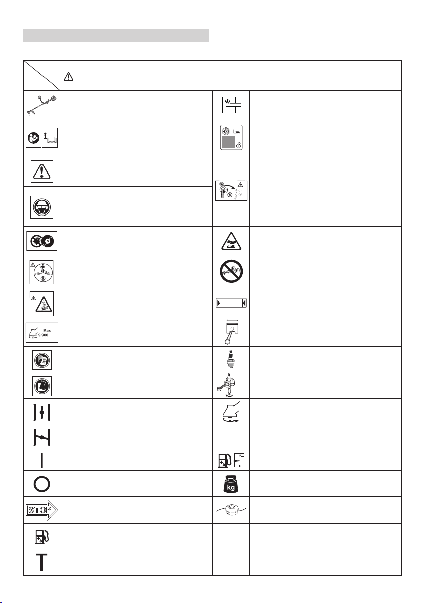
English
MEANINGS OF SYMBOLS
NOTE: Some units do not carry them.
Symbols
WARNING
The following show symbols used for the machine. Be sure that you understand their meaning before use.
Grass Trimmer / Brush Cutter Priming pump
It is important that you read, fully understand
and observe the following safety precautions
and warnings. Careless or improper use of the
unit may cause serious or fatal injury.
Read, understand and follow all warnings and
instructions in this manual and on the unit.
Always wear eye, head and ear protectors when
using this unit.
Do not use metal/rigid blades when this sign is
shown on the unit.
Keep all children, bystandards and helpers
15 m away from the unit. If anyone approaches
you, stop the engine and cutting attachment
immediately.
Be careful of thrown objects.
Guaranteed sound power level
Blade thrust may occur when the spinning
blade contacts a solid object in the critical area.
A dangerous reaction may occur causing the
entire unit and operator to be thrust violently.
This reaction is called blade thrust. As a result,
the operator may lose control of the unit which
may cause serious or fatal injury. Blade thrust is
more likely to occur in areas where it is diffi cult
to see the material to be cut.
Hot Surface – Contact with hot surface can
cause serious burns.
The hedge trimmer attachment cannot be used
on models with this label.
Indicate handle location. Arrows which show
limits for handle positioning.
Shows maximum shaft speed. Do not use the
cutting attachment whose max rpm is below the
-1
min
shaft rpm.
Gloves should be worn when necessary, e.g.,
when assembling cutting equipment.
Use anti-slip and sturdy footwear.
Choke – Run position (Open) Speed of output shaft
Choke – Start position (Closed)
On/Start Fuel tank capacity
Off /Stop
Emergency stop Cutting attachment
Fuel and oil mixture
Idle speed adjustment
L
ISO22868
L
WA, Ra(M)
2000/14/EC
6
Displacement
Spark plug
Idling speed
Idle
Max. engine output
P
Dry weight (without fuel, cutting attachment,
harness and cutting attachment guard)
Sound pressure level LpA by ISO 22868
pA, eq
Equivalent*
Measured sound power level LwA by 2000/14/
EC
Racing
Page 7

English
L
WA, Ra(G)
2000/14/EC
a
hv, eq(F)
Before using your machine
• Read the manual carefully.
• Check that the cutting equipment is correctly assembled and adjusted.
• Start the unit and check the carburetor adjustment. See “MAINTENANCE”.
NOTE: Equivalent noise level / vibration level are calculated as the time-weighted energy total for noise / vibration levels
* 1/2 Idle, 1/2 racing.
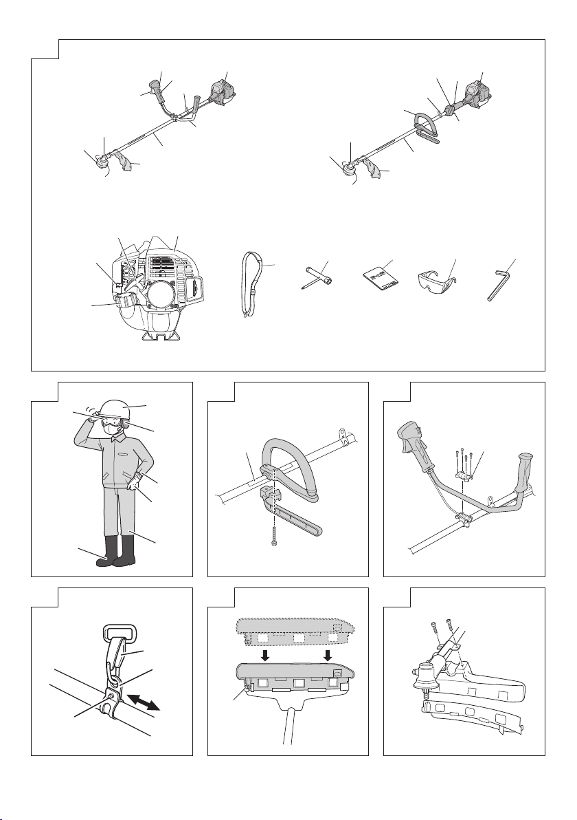
WHAT IS WHAT? (Fig. 1)
Since this manual covers several models, there may be
some diff erence between pictures and your unit. Use the
instructions that apply to your unit.
A: Fuel cap
B: Throttle trigger
C: Starter handle
D: Cutting attachment guard
E: Cutting attachment
F: Drive shaft tube
G: Handle
H: Hanger
I: Ignition switch
J: Harness (if so equipped)
K: Throttle trigger lockout
L: Choke lever
M: Engine
N: Gear case
O: Combi box spanner
P: Handling instructions
Q: Goggles
R: Hex bar wrench
WARNINGS AND SAFETY
INSTRUCTIONS
Pay special attention to statements preceded by the
following words:
Indicates a strong possibility of severe personal injury or
CAUTION
Indicates a possibility of personal injury or equipment
NOTE
Helpful information for correct function and use.
Operator safety
○ Wear head protection (1). (Fig. 2)
○ Always wear a safety face shield or goggles (2). (Fig. 2)
○ Wear approved hearing protection (3). (Fig. 2)
Long-term exposure to noise can result in permanent
Pay attention to your surroundings. Be aware of any
Remove safety equipment immediately upon shutting off
○ Always wear heavy, long-sleeved shirts (4) and long
Do not wear loose clothing, jewelry, short pants, sandals
Secure hair so it is above shoulder length.
Guaranteed sound power level LwA by 2000/14/
EC
Racing
Vibration level by ISO 22867
Front or Left handle / Equivalent*
under various working conditions with the following time distribution:
WARNING
loss of life, if instructions are not followed.
damage, if instructions are not followed.
hearing impairment.
bystanders who may be signaling a problem.
engine.
pants (5) and non-slip boots (6) and gloves (7). (Fig. 2)
or go barefoot.
a
hv, eq(R)
○ Do not operate this tool when you are tired, ill or under
○ Do not operate the tool at night or under bad weather
Working on slippery ground could lead to an accident if
○ Never let a child or inexperienced person operate the
○ Do not start the engine if there are any fl ammables such
○ Never start or run the engine inside a closed room or
○ Keep handles free of oil and fuel.
○ Keep hands away from cutting equipment.
○ Do not grab or hold the unit by the cutting equipment.
○ Gloves should be worn when installing or removing the
○ When the unit is shut off , make sure the cutting
○ When operation is prolonged, take a break periodically
○ Always operate the tool with proper protective equipment
○ Do not touch the spark plug area or high voltage during
○ Do not allow children near the tool during operation.
○ Do not touch the engine, muffl er cover or exhaust vent
○ Antivibration systems do not guarantee that you will
○ If you are using any medical electric/electronic devices
Unit/machine safety
○ Inspect the entire unit/machine before each use.
○ Replace parts that are cracked, chipped or damaged in
○ Make sure the cutting attachment guard and harness are
○ Keep others away when making carburetor adjustments.
○ Use only accessories as recommended for this unit/
7
Vibration level by ISO 22867
Rear or Right handle / Equivalent*
Uncertainty
K
the infl uence of alcohol, drugs or medication.
conditions when visibility is poor. And do not operate the
tool when it is raining or right after it has been raining.
you lose your balance.
machine.
as dry leaves, waste paper or fuel in the vicinity.
building. Breathing exhaust fumes can kill.
cutting attachment. Failure to do so may result in injury.
attachment has stopped before the unit is set down.
so that you may avoid possible Hand-Arm Vibration
Syndrome (HAVS) which is caused by vibration.
WARNING
and clothing. Failure to do so may result in accidents
such as burns or injuries. (Fig. 2)
operation. Doing so may result in electric shock.
during or shortly after operation. Doing so may result in
burn or injury.
not sustain Hand-Arm Vibration Syndrome or carpal
tunnel syndrome. Therefore, continual and regular users
should monitor closely the condition of their hands and
fi ngers. If any of the above symptoms appear, seek
medical advice immediately.
such as a pacemaker, consult your physician as well as
the device manufacturer prior to operating any power
equipment.
Replace damaged parts. Check for fuel leaks and make
sure all fasteners are in place and securely tightened.
any way before using the unit/machine. Faulty parts may
increase the risk of accidents and may lead to an injury.
properly attached. Do not operate if cutting attachment
guard and harness is not properly attached.
machine by the manufacturer.
Page 8

English
○ Before operation, make sure that there are no tools such
as the adjustment key or spanner still attached to the
unit.
WARNING
○ Never modify the unit/machine in any way. Do not use
your unit/machine for any job except that for which it is
intended.
○ Non-authorized modifi cations and/or accessories may
result in serious personal injury or the death of the
operator or others.
Fuel safety
○ Mix and pour fuel outdoors and where there are no
sparks or fl ames.
○ Use a container approved for fuel.
○ Move at least 3 m away from fueling site before starting
engine.
○ Stop engine before removing fuel cap. Do not remove
the fuel cap during operation.
○ Empty the fuel tank before storing the unit/machine. It is
recommended that the fuel be emptied after each use. If
fuel is left in the tank, store so fuel will not leak.
WARNING
○ Fuel is easy to ignite or get explosion or inhale fumes, so
that pay special attention when handling or fi lling fuel.
○ Do not smoke or allow smoking near fuel or the unit/
machine or while using the unit/machine.
○ Wipe up all fuel spills before starting engine.
○ Store unit/machine and fuel in area where fuel vapors
cannot reach sparks or open fl ames from water heaters,
electric motors or switches, furnaces. etc.
○ When using the unit in dry areas, make sure that fi re
extinguishing equipment is readily available.
○ If you shut off the engine for refueling, make sure the unit
has cooled down before adding fuel.
Cutting safety
○ Do not cut any material other than grass and brush.
○ Inspect the area to be cut before each use.
Remove objects which can be thrown or become
entangled.
Do not operate in areas where there are tree roots or
rocks.
○ For respiratory protection, wear an aerosol protection
mask when cutting the grass after insecticide is
scattered.
○ Keep others including children, animals, bystanders and
helpers outside the 15 m hazard zone. Stop the engine
immediately if you are approached.
○ Please exercise caution as engine startup may be
delayed after pulling the starter handle.
○ Always keep the engine on the right side of your body.
○ Hold the unit/machine fi rmly with both hands.
○ Keep fi rm footing and balance. Do not over-reach.
Losing your balance during work may lead to an injury.
○ Keep all parts of your body away from the muffl er and
cutting attachment when the engine is running.
○ Keep cutting attachment below knee level.
○ Please exercise caution when operating in areas where
electrical cables or gas pipes are present.
○ Do not operate the cutting attachment for anything but
clearing grass or bushes. Avoid operations where the
cutting attachment may touch water such as puddles
or dig into dirt. Failure to do so may result in injury or
damage to the unit.
○ Avoid prolonged use at low speed range in which
vibration is high. Doing so may result in engine damage.
○ When relocating to a new work area, or inspecting,
adjusting or exchanging the unit’s cutting attachments,
accessories, etc., be sure to shut off the machine and
ensure that all cutting attachments are stopped.
○ Never place the machine on the ground when running.
○ Never touch the cutting attachment when it is rotating.
○ Always ensure that the engine is shut off and any cutting
attachments have completely stopped before clearing
debris or removing grass from the cutting attachment.
○ Always carry a fi rst-aid kit when operating any power
equipment.
○ Turn off the engine and make sure the cutting attachment
has come to a full stop before removing the unit from
your body or before leaving the unit unattended.
○ If you accidentally bump or drop the unit, inspect it
immediately to make sure there are no damage, cracks
or deformations.
○ If the tool is operating poorly and produces strange noise
or vibrations, turn off the engine immediately and ask
your dealer to have it inspected and repaired.
Continued use under these conditions could lead to
injury or tool damage.
○ Use in accordance with local laws and regulations.
Maintenance safety
○ Maintain the unit/machine according to recommended
procedures.
○ Disconnect the spark plug before performing
maintenance except for carburetor adjustments.
○ Keep others away when making carburetor adjustments.
○ Use only genuine HITACHI replacement parts as
recommended by the manufacturer.
CAUTION
Do not disassemble the recoil starter. There is a
possibility of personal injury with recoil spring.
WARNING
Improper maintenance could result in serious engine
damage or in serious personal injury.
Transport and storage
○ Carry the unit/machine by hand with the engine stopped
and the muffl er away from your body.
○ Allow the engine to cool, empty the fuel tank, and secure
the unit/machine before storing or transporting. Failure to
do so may result in fi re or accidents.
○ Empty the fuel tank before storing the unit/machine. It is
recommended that the fuel be emptied after each use. If
fuel is left in the tank, store so fuel will not leak.
○ Store unit/machine out of the reach of children.
○ Clean and maintain the unit carefully and store it in a dry
place.
○ Make sure engine switch is off when transporting or
storing.
○ When transporting and storing, either remove the cutting
attachment or place the blade cover over the blade.
○ You have to secure the machine during transport to
prevent loss of fuel, damage or injury.
○ If a warning label cannot be read, peels off or becomes
indistinct, replace it with a new one. To purchase new
labels, contact Hitachi Authorized Service Centers.
If situations occur which are not covered in this manual, take
care and use common sense. Contact Hitachi Authorized
Service Centers if you need assistance.
SPECIFICATIONS
The SPECIFICATIONS of this machine are listed in the table
on page 38.
NOTE
All data subject to change without notice.
8
Page 9

ASSEMBLY PROCEDURES
Installation of handle
(1) Loop handle type (Fig. 3)
Attach the handle to the drive shaft tube with the angle
towards the engine.
Adjust the location to the most comfortable position
before operation.
Make sure to securely attach the handle with the 2 bolts.
NOTE
If your unit has handle location label (8) on drive shaft
tube, follow the illustration.
(2) Bike handle type (Fig. 4)
Remove the handle bracket (9) from the assembly.
Place the handle and attach the handle bracket with four
bolts lightly. Adjust to appropriate position. Then attach it
fi rmly with the bolts.
Installation of harness
(If so equipped)
WARNING
If the product includes a harness, always make sure to
use it.
Attach the harness hook (10) to the hanger (11) on the drive
shaft tube. (Fig. 5)
Adjust the length of the harness for easy operation of the
tool.
NOTE
You may need to adjust the position of the hangar (11)
to balance the unit. To do so, loosen bolt (12) and adjust
the position of hangar (11). After adjusting as necessary,
make sure to securely tighten the bolt (12). (Fig. 5)
Installation of cutting attachment guard
WARNING
If an incorrect or faulty guard is fi tted, this may cause
serious personal injury.
CAUTION
Some cutting attachment guards are equipped with
sharp line limiters. Be careful with handling it.
NOTE
○ When using a trimmer head with two piece type cutting
attachment guard, attach the guard extension to the
cutting attachment guard, then tighten the bolt (13).
(Fig. 6)
○ The guard extension is already attached to the cutting
attachment guard at the time of purchase.
○ The guard bracket may come already mounted to the
gear case on some models.
Align the cutting attachment guard with the guard bracket
and secure it to the drive shaft tube, using the bolt and cover
bracket. (Fig. 7)
Installation of cutting attachment
WARNING
○ Install the cutting attachment properly and securely as
instructed in the handling instructions.
If not attached properly or securely, it may come off and
cause serious and/or fatal injury.
○ Do not install or remove cutting attachments while the
engine is running.
○ Always use genuine Hitachi cutting attachments and
metal fi ttings.
Installation of semi-auto cutting head
1. Function
Automatically feeds more nylon cutting line when it is
tapped at low rpm (not greater than 4500 min
-1
).
English
Specifi cations
Type of
Code
attaching
No.
screw
6696454 Female screw
Applicable nylon cord
Cord diameter: Φ3.0 mm Length: 2 m
Cord diameter: Φ2.4 mm Length: 4 m
2. Precautions
○ The case must be securely attached to the cover.
○ Check the cover, case and other components for cracks
or other damage.
○ Check the case and button for wear.
If the wear limit mark (14) on the case is no longer visible
or there is a hole in the bottom (15) of the button, change
the new parts immediately. (Fig. 8)
○ The cutting head must be securely mounted to the unit’s
gear case/cutter case.
○ If the cutting head does not feed cutting line properly,
check that the nylon line and all components are properly
installed. Contact Hitachi Authorized Service Centers if
you need assistance.
WARNING
For Hitachi heads, use only fl exible, non-metallic line
recommended by the manufacturer. Never use wire or
wire ropes. They can break off and become a dangerous
projectile.
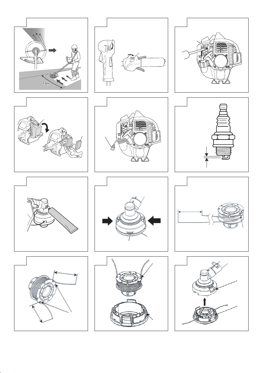
3. Installation (Fig. 9)
Insert the allen wrench (16) into the hole of the gear
case/cutter case in order to lock the drive shaft tube.
Install cutting head on gear case/cutter case of grass
trimmers/brush cutters. The mounting nut is left-hand-
threaded. Turn clockwise to loosen/counter-clockwise to
tighten.
NOTE
Since the cutter holder cap is not used here, keep it for
when a metal blade is used, if so equipped.
4. Adjusting line length
Set the engine speed as low as possible and tap the
head on the ground. The nylon line will be drawn out
about 3 cm with each tap. (Fig. 10)
Also, you can extend the nylon line by hand but the
engine must be completely stopped. (Fig. 11)
Adjust the nylon line to the proper length of 11–14 cm
before each operation.
Direction of
rotation
Counterclockwise
Size of
attaching
screw
M10xP1.25LH
OPERATING PROCEDURES
Fuel (Fig. 12)
WARNING
○ The trimmer is equipped with a two-stroke engine.
Always run the engine on fuel, which is mixed with oil.
Provide good ventilation, when fueling or handling fuel.
○ Fuel is highly fl ammable and it is possible to get seriously
injured when inhaling or spilling on your body.
Always pay attention when handling fuel. Always have
good ventilation when handling fuel inside building.
Fuel
○ Always use branded 89 octane unleaded gasoline.
○ Use genuine two-cycle oil or use a mix between 25:1 to
50:1, please consult about the mixture ratio to Hitachi
Authorized Service Centers.
○ If genuine oil is not available, use an anti-oxidant added
quality oil expressly labeled for air-cooled 2-cycle engine
use (JASO FC GRADE OIL or ISO EGC GRADE). Do not
use BIA or TCW (2-stroke water-cooling type) mixed oil.
9
Page 10

English
○ Never use multi-grade oil (10 W/30) or waste oil.
○ Never mix fuel and oil in machine’s fuel tank. Always mix
fuel and oil in a separate clean container.
Always start by fi lling half the amount of gasoline, which is
to be used.
Then add the whole amount of oil. Mix (shake) the fuel
mixture. Add the remaining amount of gasoline.
Mix (shake) the fuel-mix thoroughly before fi lling the fuel
tank.
Mixing amount of two-cycle oil and gasoline
Gasoline (Liter)
0.5 10 ——— 20
1 20 ——— 40
2 40 ——— 80
4 80 ——— 160
Fueling
WARNING
○ Always shut off the engine and let it cool for a few
minutes before refueling.
Do not smoke or bring fl ames or sparks near the fueling
site.
○ Slowly open the fuel tank, when fi lling up with fuel, so
that possible over-pressure disappears.
○ Tighten the fuel tank cap carefully, after fueling.
○ Always move the unit at least 3 m from the fueling area
before starting.
○ Always wash any spilled fuel from clothing immediately
with soap.
○ Be sure to check any fuel leakage after refueling.
○ Before fueling, in order to remove static electricity from
the main body, the fuel container and the operator,
please touch the ground that is slightly damp.
Before fueling, clean the tank cap area carefully, to ensure
that no dirt falls into the tank. Make sure that the fuel is well
mixed by shaking the container, before fueling.
Starting
WARNING
○ Before starting the tool, ensure that the cutting
attachment is not touching any objects or the ground.
Otherwise, the cutting attachment may unexpectedly
rotate and cause an injury.
○ Ensure that the cutting attachment does not rotate while
the engine is idling. If it does rotate, adjust the idle speed
according to the instructions in “Idle speed adjustment” in
the “MAINTENANCE” section. If the cutting attachment
still rotates after this adjustment, immediately stop the
engine and cease use, then bring the tool to the nearest
Hitachi Authorized Service Center.
CAUTION
Ensure that the throttle outer end is in the holder.
(1) Starting the cold engine
1. Set ignition switch (17) to ON position. (Fig. 13)
2. Push priming bulb (18) several times so that fuel fl ows
through return pipe (19). (Fig. 14)
3. Set choke lever (20) to START position (closed) (A).
(Fig. 15)
4. Pull recoil starter briskly, taking care to keep the handle
in your grasp and not allowing it to snap back. (Fig. 16)
5. When you hear the engine want to start, return choke
lever to RUN position (open) (B). (Fig. 15)
6. Pull recoil starter briskly again. (Fig. 16)
NOTE
If engine does not start, repeat procedures from 2 to 5.
Two-cycle oil (ml)
Ratio 50:1 Ratio 25:1
7. Then allow the engine about 2–3 minutes to warm up
before subjecting it to any load.
8. Check that the cutting attachment does not rotate when
the engine is idling.
(2) Starting the warm engine
Use only 1, 2, 6 and 8 of the starting procedure for a cold
engine.
If the engine does not start, use the same starting
procedure as for a cold engine.
Cutting
WARNING
○ Always use the harness (if so equipped) and wear the
proper attire and protective equipment when operating
the unit. (Fig. 17)
○ Keep others including children, animals, bystanders and
helpers outside the 15 m hazard zone. Stop the engine
immediately if you are approached. (Fig. 18)
○ When grass or vines wrap around attachment, stop
engine and attachment and remove them. Continuing
operation with grass or vines wrapped around the
attachment may result in damages such as early
abrasion of the clutch.
CAUTION
Use and points of caution will vary depending on the type
of cutting attachment. For safe use, make sure to follow
the instructions and guidelines provided with each type.
NOTE
○ Press the quick release button or pull emergency release
fl ap (If so equipped) in the event of emergency. (Fig. 19)
○ Use in accordance with local laws and regulations.
(1) Using a semi-auto cutting head
○ Set the engine at high speed when using this attachment.
○ Cut grass from left to right. The cut grass will be
discharged away from the body, minimizing transfer to
your clothes. (Fig. 20)
○ With nylon cord, use about 2 cm of the end of the cord
to cut grass. Using the full length of the cord will reduce
rotation speed and make cutting diffi cult.
NOTE
Automatically feeds more nylon cutting line when it is
tapped at low rpm (not greater than 4500 min
WARNING
○ This product is equipped with a line limiter that will
automatically cut any excess cord. When operating the
unit, do not remove the guard or line limiter.
As the resistance is greater for nylon cords as opposed
to blades, mishandling could increase engine load and
result in damage.
○ Do not use with the engine set at low speeds. If the
engine speed is low, grass may wrap around the
attachment, causing the clutch to slip which could result
in clutch abrasion.
○ With nylon cord cutters, always use over 15 cm of cord.
If the length of the cord is too short, rotation speed will
increase and may cause damage to the nylon cord
cutter. As the curved drive shaft tube model in particular
is not equipped with a deceleration mechanism, the
possibility of increased rotation speed for the cutting
attachment is high.
Stopping (Fig. 21)
Decrease engine speed and run at an idle for a few minutes,
then turn off ignition switch (17).
WARNING
A cutting attachment can injure while it continues to spin
after the engine is stopped or power control is released.
When the unit is turned off , make sure the cutting
attachment has stopped before the unit is set down.
-1
).
10
Page 11

MAINTENANCE
MAINTENANCE, REPLACEMENT OR REPAIR OF THE
EMISSION CONTROL DEVICES AND SYSTEMS MAY
BE PERFORMED BY ANY NON-ROAD ENGINE REPAIR
ESTABLISHMENT OR INDIVIDUAL.
Carburetor adjustment (Fig. 22)
The carburetor is a precision part that mixes air and fuel, and
it is designed to ensure high performance from the engine.
Before the tool is shipped from the factory, its carburetor is
adjusted during a test run. Only make adjustments if it is
necessary because of environmental conditions (the climate
or atmospheric pressure), the type of fuel, the type of twocycle oil, etc.
WARNING
○ Because the carburetor is manufactured with a high
degree of precision, do not disassemble it.
○ For this product, the only setting of the carburetor that
can be adjusted is the idle speed (T).
○ Never start the engine without the complete clutch cover
and tube assembled! Otherwise the clutch can come
loose and cause personal injuries.
T = Idle speed adjustment screw.
Idle speed adjustment (T)
WARNING
○ When the engine is stopped, do not excessively turn
the idle speed adjustment screw (T) in a clockwise
direction. Otherwise, when the engine starts, the cutting
attachment may unexpectedly rotate and cause an
injury.
○ Do not adjust the idle speed adjustment screw (T) for
any reason other than to adjust the idling.
Run the engine while adjusting the idling.
(1) If the engine stops during idling
Start the engine, and slowly turn the idle speed
adjustment screw (T) in a clockwise direction until it is in
a position at which the engine rotates smoothly. At that
time, ensure that the cutting attachment is not spinning.
(2) If the cutting attachment rotates during idling
Slowly turn the idle speed adjustment screw (T) in a
counter-clockwise direction until it is in a position at
which the cutting attachment does not rotate. At that
time, ensure that the rotation of the engine is smooth.
WARNING
If the cutting attachment still rotates after adjustment of
the idle speed adjustment screw (T), immediately stop
the engine and cease use, then contact the nearest
Hitachi Authorized Service Center.
Air fi lter (Fig. 23)
The air fi lter (21) must be cleaned from dust and dirt in order
to avoid:
○ Carburetor malfunctions.
○ Starting problems.
○ Engine power reduction.
○ Unnecessary wear on the engine parts.
○ Abnormal fuel consumption.
Clean the air fi lter daily or more often if working in
exceptionally dusty areas.
Loosen the screw (22), then open the air fi lter cover and
remove the air fi lter (21). Rinse it in warm soap suds.
Check that the fi lter is dry before reassembly.
An air fi lter that has been used for some time cannot be
cleaned completely. Therefore, it must regularly be replaced
with a new one. A damaged fi lter must always be replaced.
English
Fuel fi lter (Fig. 24)
Remove the fuel fi lter (23) from the fuel tank, and replace it if
it is dirty.
NOTE
A blocked fuel fi lter (23) can prevent the supply of fuel and
cause a rotation malfunction of the engine.
Spark plug (Fig. 25)
The spark plug condition is infl uenced by:
○ An incorrect carburetor setting.
○ Wrong fuel mixture (too much oil in the gasoline)
○ A dirty air fi lter.
○ Hard running conditions (such as cold weather).
These factors cause deposits on the spark plug electrodes,
which may result in malfunction and starting diffi culties. If
the engine is low on power, diffi cult to start or runs poorly at
idling speed, always check the spark plug fi rst.
If the spark plug is dirty, clean it and check the electrode
gap. Re-adjust if necessary. The correct gap is 0.6 mm. The
spark plug should be replaced after about 100 operation
hours or earlier if the electrodes are badly eroded.
NOTE
In some areas, local law requires using a resistor spark
plug to suppress ignition signals. If this machine was
originally equipped with resistor spark plug, use same
type of spark plug for replacement.
Gear case (Fig. 26)
Check gear case or angle gear for grease level about every
50 hours of operation by removing the grease fi ller plug on
the side of gear case.
If no grease can be seen on the fl anks of the gears, fi ll the
gear case with quality lithium based multipurpose grease up
to 3/4. Do not completely fi ll the gear case.
CAUTION
○ Make sure to remove any dirt or grit when attaching the
plug to its original position.
○ Before attempting inspection or maintenance of the gear
case, make sure the case has cooled.
Semi-auto cutting head
Nylon line replacement
1. Remove the case (24) by fi rmly pushing inward the
locking tabs with your thumbs as shown in Fig. 27.
2. After removing the case, take out the reel and discard
the remaining line.
3. Fold the new nylon line unevenly in half as shown in
picture.
Hook the U-shaped end of the nylon line into the groove
(25) on the center partition of the reel.
Wind both halves of the line on the reel in the same
direction, keeping each half of the line on its own side of
the partition. (Fig. 28)
4. Push each line into the stopper holes (26), leaving the
loose ends approx. 10 cm in length. (Fig. 29)
5. Insert both loose ends of the line through the cord guide
(27) when placing the reel in the case. (Fig. 30)
NOTE
When placing a reel in the case, try to line up the stopper
holes (26) with the cord guide (27) for easier line release
later.
6. Place the cover over the case so that the cap locking
tabs (28) on the case meet the long holes (29) on the
cover. Then push the case securely until it clicks into
place. (Fig. 31)
7. The initial cutting line length should be approx. 11–14 cm
and should be equal on both sides. (Fig. 32)
11
Page 12

English
For long-term storage
Drain all fuel from the fuel tank. Start and let engine run until
it stops. Repair any damage which has resulted from use.
Clean the unit with a clean rag, or the use of high pressure
air hose. Put a few drops of two-cycle engine oil into the
cylinder through the spark plug hole, and spin the engine
over several times to distribute oil.
Cover the unit and store it in a dry area.
Maintenance schedule
Below you will fi nd some general maintenance instructions.
For further information please contact Hitachi Authorized
Service Centers.
Daily maintenance
○ Clean the exterior of the unit.
○ Check that the harness is undamaged.
○ Check the cutting attachment guard for damage or
cracks. Change the guard in case of impacts or cracks.
○ Check that the cutting attachment is properly centered,
sharp, and without cracks. An off -center cutting
attachment induces heavy vibrations that may damage
the unit.
○ Check that the cutting attachment nut is suffi ciently
tightened.
○ Check that nuts and screws are suffi ciently tightened.
○ Check that the unit is undamaged and free of defects.
Weekly maintenance
○ Check the starter, especially the cord and return spring.
○ Clean the exterior of the spark plug.
○ Remove the spark plug and check the electrode gap.
Adjust it to 0.6 mm, or change the spark plug.
○ Check that the angle gear is fi lled with grease up to 3/4.
○ Clean the air fi lter.
Monthly maintenance
○ Rinse the fuel tank with gasoline.
○ Clean the exterior of the carburetor and the space
around it.
○ Clean the fan and the space around it.
SELECTING ACCESSORIES
The accessories of this machine are listed on page 39.
12
Page 13

SELECTING CUTTING ATTACHMENTS
Recommended accessories for each model are presented in the table below.
For purchases, contact Hitachi Authorized Service Centers.
Please check carefully as those accessories not marked with “
List of recommended accessories
●” cannot be attached.
English
Type Name
NYLON HEAD
CH-100
(W/NYLON LINE)
NYLON HEAD
CH-100
NYLON HEAD
CH-300
(W/CUTTER HOLDER
CAP)
ALUMINUM HEADS
NYLON HEAD
CH-300
NYLON HEAD
BF-4
NYLON HEAD
TAP & GO
BF-5
NYLON HEADS
Specifi cation LOOP HANDLE
or
(mm)
Trimmer line Diameter
Blade Thickness (mm)
2.2 – 3.0
2.2 – 2.7
2.2 – 3.0
2.2 – 3.0
Diameter
4”
5”
4”
5”
or
No. of Teeth (Blade)
Feed System Adapter
Pre-Cut
Line
Manual line
feed
R M8 x 1.25
Nut
L M10 x
1.25 Nut
L M8 x 1.25
Nut
BIKE
HANDLE
CG24EC (SL)
●●●
●●●
●●●
CG27EC (SL)
●
●
CG24EC (S)
13
Page 14

English
TROUBLESHOOTING
Use the inspections in the table below if the tool does not operate normally. If this does not remedy the problem, consult your
dealer or the Hitachi Authorized Service Center.
Condition Cause Remedy
Fill the fuel tank with the correct fuel mix
(25:1-50:1)
Replace with new fuel
1.
Disconnect the spark plug and allow to dry
2. Pull the starter handle 5 or 6 times to
remove the surplus fuel
3. Attach the spark plug
4. Set the choke lever to RUN position and
pull the starter handle
Reconnect
Contact Hitachi Authorized Service Centers
for repair
Fill the fuel tank with the correct fuel mix
(25:1-50:1)
Replace with new fuel
Replace with designated part
See “SPECIFICATIONS”
Contact Hitachi Authorized Service Centers
See “Installation of cutting attachment”
Check and tighten
Fuel
system
Engine does not
start
Electrical
system
Other
Fuel
system
Engine starts
but cuts out
straightaway
Engine is apt to
cut out
Abnormal vibration
Engine is running but blade
does not move
Movement is poor
Electrical
system
Other
Fuel tank is empty or fuel level is low
Fuel tank contains old fuel (offensive odor)
Too much fuel is absorbed and spark
plug is wet
Fuel fi lter is clogged with dirt Clean the fuel fi lter
Fuel pipe is bent or disconnected Ensure that the fuel fl ows smoothly
Carburetor malfunction Contact Hitachi Authorized Service Centers
Stop switch lead has short-circuited Contact Hitachi Authorized Service Centers
Spark plug is dirty Replace or clean the spark plug
Electrode gap is too big Adjust the gap to 0.6mm
Poor connection between high tension
cable and spark plug
Electrical system malfunction Contact Hitachi Authorized Service Centers
Muffl er exhaust port is clogged with
carbon
Fuel tank is empty or fuel level is low
Fuel tank contains old fuel (offensive odor)
Two-cycle oil has not been added Contact Hitachi Authorized Service Centers
Choke lever is in START position Set the choke lever to RUN position
Air has got into fuel system Reconnect the fuel pipe or joint
Carburetor malfunction Contact Hitachi Authorized Service Centers
Ignition failure
Spark plug failure Replace with new spark plug
Electrical system failure Contact Hitachi Authorized Service Centers
Engine overheating
Wrong spark plug model
Dirty air cleaner Clean
Carbon clogging (muffl er exhaust port) Clean
Insuffi cient compression (piston, piston
ring, cylinder)
Cutting attachment is not properly
installed
Handle, handle bracket or other
fastening part is loose
Grass is wrapped round gear case Remove grass
Grass is wrapped round gear case Remove grass and dirt
14
Page 15

Condition Cause Remedy
Set the choke lever to START position to
Engine does not stop Stop switch failure
Engine stops when throttle is
closed
Blade continues rotating when
throttle is closed
Idle speed is too low
Idle speed is too high
Throttle wire is too taut
stop the engine
Cease use immediately and contact Hitachi
Authorized Service Centers
Contact Hitachi Authorized Service Centers
Contact Hitachi Authorized Service Centers
English
15
Page 16

Español
SIGNIFICADO DE LOS SÍMBOLOS
NOTA: Algunas unidades no están provistos de ellos.
Símbolos
ADVERTENCIA
A continuación se muestran los símbolos utilizados para la máquina. Asegúrese de comprender su signifi cado
antes de utilizar el dispositivo.
Motoguadañas / Desbrozadoras Mezcla de combustible y aceite
Es importante que lea, entienda totalmente
y respete las siguientes precauciones y
advertencias de seguridad. El uso descuidado
o incorrecto de la unidad podría provocarle
lesiones graves o fatales.
Lea, comprenda y siga todas las advertencias y
demás instrucciones de este manual y las que
se muestran en el aparato.
Ajuste del ralentí
Bomba de cebado
Utilice siempre protecciones para los ojos, la
cabeza y los oídos cuando utilice esta unidad.
No utilice cuchillas rígidas/de metal si el aparato
muestra este símbolo.
Mantenga a los niños, transeúntes y ayudantes
a una distancia de 15 m de la unidad. Si alguien
se acerca a usted, detenga el motor y el
mecanismo de corte de inmediato.
Tenga cuidado con los objetos que puedan salir
despedidos.
Muestra la velocidad máxima del eje. No utilice
mecanismos de corte cuyas rpm máximas sean
-1
min
inferiores a las rpm del eje.
Deben utilizarse guantes siempre que sea
necesario, por ejemplo, cuando se monten
equipos de corte.
Utilice calzado antideslizante y resistente. Desplazamiento
Estrangulador: posición de marcha RUN
(abierta)
Estrangulador: posición de arranque (cerrado)
Encendido/Arranque Velocidad del eje de salida
Nivel de potencia acústica garantizado
Puede producirse una sacudida de la cuchilla
si, al encontrarse en movimiento, ésta entra en
contacto con un objeto sólido en la zona crítica.
Puede producirse una reacción peligrosa que
sacuda violentamente el aparato y al usuario.
Esta reacción se conoce como sacudida de la
cuchilla. Como consecuencia, el usuario podría
perder el control de la unidad y provocarse
lesiones graves e incluso mortales. Existen
más probabilidades de que se produzcan
sacudidas de la cuchilla en zonas en las que
es difícil ver el material que se está cortando.
Superfi cie caliente: El contacto con la superfi cie
caliente puede causar quemaduras graves.
El accesorio recortador de setos no se puede
usar en modelos con esta etiqueta.
Indica la ubicación del asidero. Flechas que
indican los límites para la posición de la
empuñadura.
Bujía
Al ralentí
Idle
Apagado/Parada
Parada de emergencia Capacidad del depósito de combustible
16
Emisión máx. del motor
P
Page 17

Español
Peso en seco (sin combustible, accesorio de
corte, arnés y protección del accesorio de corte)
Accesorio de corte
L
ISO22868
L
WA, Ra(M)
2000/14/EC
Antes de utilizar su máquina
• Lea detenidamente el manual.
• Compruebe que el mecanismo de corte se encuentra acoplado y ajustado correctamente.
• Arranque el aparato y compruebe el ajuste del carburador. Consulte “MANTENIMIENTO”.
NOTA: Los niveles de ruido / vibración equivalentes se calculan como la energía ponderada en base al tiempo en distintas
* 1/2 al ralentí, 1/2 acelerando.
Nivel de presión acústica LpA equivalente
pA, eq
según ISO 22868*
Nivel de potencia acústica LwA medida según
2000/14/CE
Acelerando
condiciones de trabajo con la siguiente distribución de tiempo:
DESCRIPCIÓN DE LAS PARTES (Fig. 1)
Puesto que este manual cubre varios modelos, puede que
existan diferencias entre los dibujos y su unidad. Utilice las
instrucciones que se refi eran a su unidad.
A: Tapa del depósito de combustible
B: Gatillo del acelerador
C: Asidero de arranque
D: Protección del accesorio de corte
E: Accesorio de corte
F: Tubo del eje de distribución
G: Asidero
H: Colgador
I: Interruptor de encendido
J: Arnés (si viene equipado)
K: Bloqueo del gatillo del acelerador
L: Palanca del estárter
M: Motor
N: Caja de engranajes
O: Llave combinada de cubo
P: Instrucciones de manejo
Q: Gafas protectoras
R: Llave hexagonal de barra
ADVERTENCIAS E INSTRUCCIONES
L
WA, Ra(G)
2000/14/EC
a
hv, eq(F)
a
hv, eq(R)
Preste atención a su entorno. Esté atento a personas
Retírese el equipo de seguridad inmediatamente
○ Utilice siempre camisas pesadas y de manga larga (4),
No utilice prendas holgadas, joyas, pantalones cortos ni
Colóquese el pelo de forma que esté por encima de los
○ No utilice esta herramienta cuando esté cansado,
○ No opere la herramienta por la noche o bajo malas
Trabajar en terreno resbaladizo podría dar lugar a un
○ Nunca deje que niños o personas inexpertas operen la
○ No ponga en marcha el motor si hay elementos
○ Nunca ponga en marcha el motor en el interior de un
DE SEGURIDAD
Dedique especial atención a los apartados introducidos por
las siguientes palabras:
ADVERTENCIA
Indica un riesgo signifi cativo de que se produzcan daños
personales graves, e incluso la muerte, si no se siguen
las instrucciones.
PRECAUCIÓN
Indica la posibilidad de que se produzcan daños
personales o materiales si no se siguen las instrucciones.
NOTA
Indica información útil para el uso y funcionamiento
correctos de la máquina.
Seguridad del usuario
○ Utilice casco protector(1). (Fig. 2)
○ Utilice siempre una máscara o gafas protectoras (2).
(Fig. 2)
○ Utilice protección auditiva regulada (3). (Fig. 2)
La exposición prolongada al ruido puede resultar en
disfunciones auditivas permanentes.
○ Mantenga los asideros limpios sin aceite ni combustible.
○ Mantenga las manos alejadas del mecanismo de corte.
○ No agarre ni sujete la unidad por el mecanismo de corte.
○ Deben utilizarse guantes al instalar o desinstalar el
○ Cuando apague la unidad, asegúrese de que el
○ Si utiliza este dispositivo durante un periodo de tiempo
○ Opere siempre la herramienta con el equipo de
17
Nivel de potencia acústica LwA garantizado
según 2000/14/CE
Acelerando
Nivel de vibración según ISO 22867
Asidero delantero o izquierdo/Equivalente*
Nivel de vibración según ISO 22867
Asidero trasero o derecho/Equivalente*
Incertidumbre
K
que pudieran estar avisándole de un problema.
después de parar el motor.
pantalones largos (5), botas antideslizante (6) y guantes
(7). (Fig. 2)
sandalias, y nunca trabaje descalzo.
hombros.
enfermo o bajo la infl uencia del alcohol, drogas o
medicamentos.
condiciones atmosféricas en las que la visibilidad no sea
buena. Tampoco haga funcionar la herramienta cuando
esté lloviendo ni inmediatamente después de que haya
llovido.
accidente si pierde el equilibrio.
máquina.
infl amables tales como hojas secas, residuos de papel
o combustible en las proximidades.
local cerrado ni un edifi cio. La inhalación de los humos
de escape puede ser fatal.
mecanismo de corte. De lo contrario, podrían producirse
lesiones.
mecanismo de corte se haya detenido antes de apoyarla
sobre el suelo.
prolongado, tome un descanso de vez en cuando
para evitar la posibilidad de desarrollar el síndrome
por vibración en mano/brazo (SVMB), causado por las
vibraciones.
ADVERTENCIA
protección y la ropa adecuados. De lo contrario, podrían
ocasionarse accidentes como quemaduras o lesiones.
(Fig. 2)
Page 18

Español
○ No toque las zonas de chispas o de alto voltaje durante
el funcionamiento. De lo contrario podría producirse una
descarga eléctrica.
○ No permita que los niños se acerquen a la herramienta
durante su funcionamiento.
○
No toque el motor, la cubierta del silenciador ni la rejilla de
ventilación durante la operación ni inmediatamente después.
De lo contrario podrían ocasionarse quemaduras o lesiones.
○ Los sistemas antivibratorios no garantizan que no sufrirá
el síndrome por vibración en mano/brazo (SVMB) o el
síndrome del túnel carpiano. Por lo tanto, los usuarios
que utilicen el aparato asiduamente o con regularidad
deberán vigilar con atención el estado de sus manos y
dedos. Si aparece cualquiera de los síntomas citados,
deberá solicitarse inmediatamente atención médica.
○ Si utiliza algún dispositivo médico electrónico, por
ejemplo un marcapasos, consulte a su médico, así como
al fabricante del dispositivo, antes de operar cualquier
equipo mecánico.
Seguridad de la máquina
○ Inspeccione la máquina en su totalidad antes de
utilizarla. Cambie las piezas dañadas. Compruebe
que no haya fugas de combustible y asegúrese de
que todas las piezas se encuentren en su sitio y estén
correctamente apretadas.
○
Cambie las piezas agrietadas, desportilladas o deterioradas de
cualquier manera antes de poner en marcha la máquina. Las
piezas defectuosas pueden aumentar el riesgo de accidentes
y puede dar lugar a lesiones.
○ Asegúrese de que la protección del mecanismo de corte
y el arnés estén correctamente conectados. No opere la
máquina si la protección del mecanismo de corte y el
arnés no están correctamente conectados.
○ No permita que se acerquen otras personas mientras
esté ajustando el carburador.
○ Utilice únicamente accesorios según la recomendación
del fabricante para esta máquina.
○ Antes de la operación, asegúrese de que no hayan
herramientas, como la llave o la tecla de ajuste, todavía
conectadas a la unidad.
ADVERTENCIA
○ No intente en ningún momento modifi car la máquina
de ninguna manera. No utilice esta máquina para otras
tareas para las que no esté indicada.
○ Las modifi caciones no autorizadas y el uso de
accesorios no autorizados puede resultar en lesiones
personales graves o la muerte del operador u otros.
Seguridad en torno al combustible
○ Mezcle y llene el combustible al aire libre, en lugares
donde no hayan chispas ni llamas.
○ Use un recipiente autorizado para el combustible.
○ Antes de poner en marcha el motor, distánciese un
mínimo 3 metros del lugar de repostaje.
○ Antes de retirar la tapa del depósito de combustible,
detenga el motor. No retire el tapón del depósito de
combustible durante el funcionamiento.
○ Vacíe el depósito de combustible antes de almacenar
la máquina. Se recomienda vaciar el depósito de
combustible cada vez que termine de utilizar la máquina.
Si deja combustible en el depósito, guarde la máquina
de forma que no se produzcan fugas.
ADVERTENCIA
○ El combustible prende y provoca explosiones e
inhalación de humo con facilidad. Por lo tanto, preste
especial atención al manipular o recargar el combustible.
○ No fume ni deje fumar a otras personas cerca del
combustible o de la máquina mientras ésta esté en
funcionamiento.
○ Limpie los residuos de combustible antes de poner en
marcha el motor.
○ Guarde la máquina y el combustible en un lugar donde
los vapores del combustible no puedan llegar a chispas
o llamas de calentadores de agua, motores eléctricos,
interruptores, hornos, etc.
○ Al utilizar la unidad en zonas secas, asegúrese de que
exista un equipo de extinción de incendios disponible y
fácilmente accesible.
○ Si para el motor para repostar, asegúrese de que la
unidad se haya enfriado antes de añadir combustible.
Seguridad durante el corte
○ No corte ningún material que no sea hierba o maleza.
○ Inspeccione siempre la zona sobre la que va a cortar
antes de comenzar.
Retire cualquier objeto que pueda salir despedido o
enredarse.
No opere en las zonas en las que haya raíces de árboles
ni rocas.
○ Para proteger las vías respiratorias, utilice una máscara
de protección contra aerosoles cuando corte hierba tras
haber fumigado con insecticidas.
○ Mantenga a transeúntes, niños, animales y asistentes
a una distancia de 15 m de la zona de riesgo. Detenga
inmediatamente el motor si se le acerca alguna persona.
○ Proceda cuidadosamente, ya que el arranque del motor
podría retrasarse un poco tras accionar la palanca de
arranque.
○
Mantenga el motor siempre al lado derecho de su cuerpo.
○ Sujete la máquina fi rmemente con ambas manos.
○ Mantenga bien el equilibrio y los pies bien apoyados
sobre el suelo. No estire demasiado el cuerpo.
Perder el equilibrio durante el trabajo puede dar lugar a
una lesión.
○ Mantenga todas las partes del cuerpo apartadas del
silenciador y del mecanismo de corte mientras la
máquina esté en funcionamiento.
○ Mantenga el mecanismo de corte por debajo de la altura
de la rodilla.
○ Proceda con precauciones a la hora de operar en zonas
en las cuales haya cables eléctricos o tuberías de gas
presentes.
○ No opere el mecanismo de corte para nada que no sea
despejar de césped y arbustos. Evite operaciones en las
que el mecanismo de corte pueda entrar en contacto
con el agua, como el trabajo en charcos o excavación
en la tierra. De lo contrario podrían producirse lesiones o
desperfectos en la unidad.
○ Evite el uso prolongado a niveles de baja velocidad en
los que la vibración es elevada. De lo contrario podría
dañarse el motor.
○ Al trasladarse a una nueva zona de trabajo o al
Inspeccionar, ajustar o cambiar los mecanismo de corte
de la unidad, los accesorios, etc., asegúrese de apagar
la máquina y de que todos los mecanismos de corte se
hayan detenido.
○ Jamás coloque la máquina sobre el suelo cuando esté
en marcha.
○ Nunca toque el mecanismo de corte mientras esté
rotando.
○ Asegúrese siempre de que el motor esté apagado y
de que todos los mecanismos de corte hayan parado
completamente antes de eliminar restos o hierba del
mecanismo de corte.
○ Lleve siempre un botiquín de primeros auxilios consigo
cuando opere cualquier equipo motorizado.
○ Apague el motor y asegúrese de que el mecanismo de
corte haya parado totalmente antes de retirar la unidad
de su cuerpo y antes de dejar la unidad sin vigilancia.
○ Si accidentalmente golpea o se le cae la unidad,
inspecciónela inmediatamente para cerciorarse de que
no hay daños, grietas ni deformaciones.
18
Page 19

○ Si la herramienta no está funcionando correctamente y
produce ruidos o vibraciones extraños, apague el motor
inmediatamente y contacte con su distribuidor para que
revise y repare la máquina.
El uso continuado en estas condiciones podría ocasionar
lesiones o daños en las herramientas.
○ Haga uso de la máquina en conformidad con las
normativas y las leyes aplicables.
Seguridad durante el mantenimiento
○ Realice el mantenimiento de la máquina según el
procedimiento recomendado.
○ Antes de iniciar el mantenimiento, desconecte la bujía,
excepto para ajustar el carburador.
○ No permita que se acerquen otras personas mientras
esté ajustando el carburador.
○ Utilice únicamente piezas de repuesto originales
HITACHI como recomienda el fabricante.
PRECAUCIÓN
No desmonte el arrancador de retroceso. El resorte
del arrancador puede ocasionarle lesiones personales
graves.
ADVERTENCIA
El mantenimiento incorrecto podría conducir a una
avería seria del motor o a heridas graves.
Transporte y almacenamiento
○ Transporte la máquina en la mano con el motor apagado
y el silenciador apartado del cuerpo.
○ Antes de almacenar o transportar la máquina, espere
a que se haya enfriado el motor, vacíe el depósito de
combustible y sujete bien la máquina. De lo contario
podrían producirse incendios o accidentes.
○ Vacíe el depósito de combustible antes de almacenar
la máquina. Se recomienda vaciar el depósito de
combustible cada vez que termine de utilizar la máquina.
Si deja combustible en el depósito, guarde la máquina
de forma que no se produzcan fugas.
○ Almacene la máquina fuera del alcance de niños.
○ Limpie y lleve a cabo el mantenimiento de la máquina
cuidadosamente y guárdela en un lugar seco.
○ Asegúrese de que el motor esté apagado al transportar
o almacenar la máquina.
○ Al transportar y almacenar, extraiga el accesorio de
corte o coloque la cubierta de la cuchilla sobre la hoja.
○ Debe asegurar la máquina durante el transporte para
prevenir pérdidas de combustible, daños o lesiones.
○ Si aparece ilegible, despegada o borrosa alguna de las
etiquetas de advertencia, sustitúyala por una nueva.
Para adquirir etiquetas nuevas, póngase en contacto
con un centro de servicio autorizado Hitachi.
Si se producen situaciones no previstas en este manual,
utilice el sentido común. Si necesita ayuda, póngase en
contacto con un centro de servicio autorizado Hitachi.
ESPECIFICACIONES
Las ESPECIFICACIONES de la máquina se indican en la
tabla de la página 38.
NOTA
Todos los datos están sujetos a cambios sin previo aviso.
PROCEDIMIENTOS DE MONTAJE
Instalación del asidero
(1) Tipo de asa de lazo (Fig. 3)
Acople el asidero al tubo del eje de distribución en
ángulo con el motor.
Ajuste su posición de la manera que le resulte más
cómoda antes de ponerlo en funcionamiento.
Español
Asegúrese de conectar fi rmemente el asa con los
2 tornillos.
NOTA
Si su unidad tiene una etiqueta que muestre la ubicación
del asidero (8) en el tubo del eje de distribución, siga la
ilustración.
(2) Tipo de asa de mango (Fig. 4)
Retire la abrazadera del asidero (9) del conjunto.
Coloque el asidero y acople la abrazadera del asidero
suavemente con cuatro tornillos. Ajústela en la posición
adecuada. A continuación apriétela con los tornillos.
Instalación del arnés
(si viene equipado)
ADVERTENCIA
Si el producto incluye un arnés, asegúrese siempre de
utilizarlo.
Enganche el gancho del arnés (10) al asa (11) del tubo del
eje de distribución. (Fig. 5)
Ajuste la longitud del arnés para facilitar el funcionamiento
de la herramienta.
NOTA
Puede ser necesario ajustar la posición del asidero (11)
para equilibrar la unidad. Para hacerlo, afl oje el perno
(12) y ajuste la posición del asidero (11). Después de
ajustar según sea necesario, asegúrese de apretar con
fi rmeza el perno (12). (Fig. 5)
Instalación de la protección del accesorio de corte
ADVERTENCIA
Si se coloca un protector incorrecto o defectuoso,
podrían ocasionarse lesiones personales graves.
PRECAUCIÓN
Algunos protectores del accesorio de corte están
equipados con limitadores de línea afi lados. Tenga
cuidado al manipularlos.
NOTA
○ Al usar un cabezal de desbrozadora con protección
del accesorio de corte de tipo dos piezas, acople la
extensión del protector a la protección del accesorio de
corte y, apriete el perno (13). (Fig. 6)
○ La extensión de la protección ya está conectada a la
protección del accesorio de corte en el momento de la
compra.
○ En algunos modelos, el soporte del protector puede
venir ya montado en la caja de engranajes.
Alinee el protector del accesorio de corte con el soporte
del protector y sujételo bien al tubo del eje de distribución
usando el perno y el soporte de la cubierta. (Fig. 7)
Instalación del accesorio de corte
ADVERTENCIA
○ Instale el accesorio de corte correcta y fi rmemente como
se indica en las instrucciones de manejo.
Si no se coloca correcta y fi rmemente, podría soltarse y
provocar lesiones graves y/o fatales.
○ No instale ni retire los accesorios de corte mientras el
motor esté en marcha.
○ Utilice siempre accesorios de corte y metálicos Hitachi
originales de corte.
Instalación del cabezal de corte semiautomático
1. Función
Alimenta automáticamente más líneas de corte de nylon
cuando se golpea a un rpm bajo (no más de 4500 min
-1
).
19
Page 20

Español
Especifi caciones
Núm. de
código
6696454
Cable de nylon aplicable
Diámetro del cable: Φ3,0 mm de longitud: 2 m
Diámetro del cable: Φ2,4 mm de longitud: 4 m
2. Precauciones
○ La caja debe fi jarse bien a la cubierta.
○ Compruebe que la cubierta, la caja y otros componentes
○ Compruebe el desgaste de la caja y el botón.
Si la marca del límite de desgaste (14) de la caja ya no
○ El cabezal de corte debe fi jarse bien a la caja de
○ Si el cabezal de corte no alimenta bien la línea de
Para cabezales Hitachi, utilice únicamente la línea
3. Instalación (Fig. 9)
Inserte la llave Allen (16) en el orifi co de la caja de
Instale el cabezal de corte en la caja de engranajes/caja
NOTA
Ya que la tapa del soporte de la cuchilla no se utiliza
4. Ajuste de la longitud de línea
Ajuste la velocidad del motor tan lenta como sea posible
Además, puede extender las líneas de nylon
Ajuste la línea de nylon a una longitud de 11-14 cm antes
Tipo de
tornillo de
sujeción
Tornillo hembra
no tengan grietas ni otros daños.
se ve o hay un agujero en la parte inferior (15) del botón,
cambie las piezas nuevas inmediatamente. (Fig. 8)
engranajes/caja de corte de la unidad.
corte, compruebe que la línea de nylon y todos los
componentes estén bien instalados. Si necesita
ayuda, póngase en contacto con un centro de servicio
autorizado Hitachi.
ADVERTENCIA
fl exible y no metálica recomendada por el fabricante. No
utilice nunca cables ni cables de acero. Estos podrían
romperse y actuar como proyectiles peligrosos.
engranajes/caja de corte para bloquear el tubo del eje
de distribución.
de corte del montaguadañas/la desbrozadora. La tuerca
de montaje se enrosca hacia la izquierda. Gire en el
sentido de las agujas del reloj para afl ojar y en el sentido
contrario a las agujas del reloj para apretar.
aquí, guárdela para cuando se utilice una cuchilla de
metal, si viene equipado.
y apriete el cabezal contra el suelo. La línea de nylon
saldrá unos 3 cm con cada golpe. (Fig. 10)
manualmente, pero el motor debe estar completamente
parado. (Fig. 11)
de cada funcionamiento.
Dirección de
giro
En el sentido
contrario a las
agujas del reloj
Tamaño de
tornillo de
sujeción
M10xP1,25LH
PROCEDIMIENTOS DE
FUNCIONAMIENTO
Combustible (Fig. 12)
ADVERTENCIA
○ La segadora está equipada con un motor de dos tiempos.
El motor debe funcionar siempre con combustible
mezclado con aceite.
Asegúrese de que existe una buena ventilación en los
lugares de manipulación o repostaje de combustible.
○ El combustible contiene sustancias altamente
infl amables, por lo que existe la posibilidad de sufrir
lesiones graves por inhalación o por derrames sobre el
cuerpo.
20
Preste siempre atención cuando manipule el
combustible. Cuando manipule el combustible en
interiores, asegúrese de que haya buena ventilación en
todo momento.
Combustible
○ Use siempre gasolina sin plomo de 89 octanos.
○ Utilice aceite de dos tiempos original o una mezcla de
25:1 a 50:1. Consulte la proporción de la mezcla con un
centro de servicio autorizado Hitachi.
○ Si no hay aceite original disponible, utilice un aceite con
antioxidante de calidad que esté indicado expresamente
según el etiquetado para motores de dos tiempos
refrigerados por aire (JASO FC GRADE OIL o ISO EGC
GRADE). No utilice aceite mezclado BIA o TCW (para
motores de 2 tiempos refrigerados por agua).
○ No utilice aceites multigrado (10 W/30) ni residual.
○ Nunca mezcle combustible y aceite en el depósito
de combustible de la máquina. Mezcle siempre el
combustible y el aceite en un recipiente limpio y
destinado a este fi n.
Comience siempre por llenar la mitad del combustible que
va a utilizar.
A continuación, añada todo el aceite. Agite la mezcla de
combustible. Añada el resto de gasolina.
Antes de llenar el depósito de combustible, agite bien la
mezcla.
Cantidad de mezcla de aceite de dos tiempos y gasolina
Gasolina (litros)
0,5 10 ——— 20
1 20 ——— 40
2 40 ——— 80
4 80 ——— 160
Recarga de combustible
ADVERTENCIA
○ Antes de repostar el combustible, apague el motor y
deje que se enfríe durante unos minutos.
No fume ni acerque llamas o chispas al lugar en el que
se realiza el repostaje.
○ Para llenar el depósito de combustible, abra lentamente
la tapa del depósito para que desaparezca la
sobrepresión que pudiera existir.
○ Después del repostaje, cierre y apriete bien la tapa del
depósito de combustible.
○ Antes de arrancar la máquina, aleje siempre la máquina
un mínimo de 3 m del área de repostaje.
○ Lave la ropa inmediatamente con jabón si se vierte
combustible sobre ella.
○ Asegúrese de verifi car que no existan pérdidas de
combustible después del repostaje.
○ Antes de repostar, y con el fi n de descargar la
electricidad estática del cuerpo principal, del recipiente
y del operario, toque el suelo donde esté ligeramente
humedecido.
Antes de repostar el combustible, limpie cuidadosamente
la zona de la tapa del depósito para asegurarse de que
no entra suciedad en el depósito. Asegúrese de que el
combustible está bien mezclado agitando el recipiente
antes de llenar el depósito.
Inicio
ADVERTENCIA
○ Antes de iniciar la herramienta, asegúrese de que el
accesorio de corte no está en contacto con ningún
objeto o con el suelo. De lo contrario, el equipo de corte
puede girar inesperadamente y causar una lesión.
Aceite de dos tiempos (ml)
Proporción 50:1 Proporción 25:1
Page 21

○ Asegúrese de que el accesorio de corte no gire cuando
el motor está al ralentí. Si gira, ajuste la velocidad de
ralentí de acuerdo con las instrucciones en “Ajuste
del ralentí” de la sección “MANTENIMIENTO”. Si el
accesorio de corte sigue girando después de este
ajuste, pare inmediatamente el motor y cese el uso, y
lleve a continuación la herramienta al Centro de Servicio
Autorizado de Hitachi más cercano.
PRECAUCIÓN
Asegúrese de que el extremo exterior del acelerador
está en el soporte.
(1) Puesta en marcha del motor en frío
1. Lleve la llave de ignición (17) a la posición ON
(encendido). (Fig. 13)
2. Presione el cebador (18) repetidamente para que el
combustible fl uya por el tubo de retorno (19). (Fig. 14)
3. Ajuste la palanca del estrangulador (20) en la posición
de arranque START (cerrado) (A). (Fig. 15)
4. Tire enérgicamente del arrancador de retroceso,
tomando la precaución de mantener el asidero bien
sujeto para evitar que se escape de la mano. (Fig. 16)
5. Cuando escuche el amago de arranque del motor,
devuelva la palanca del estárter a la posición de marcha
RUN (abierto) (B). (Fig. 15)
6. Vuelva a tirar enérgicamente del arrancador de
retroceso. (Fig. 16)
NOTA
Si el motor no arranca, repita los pasos 2 a 5.
7. A continuación, deje que el motor se caliente durante
2–3 minutos antes de someterlo a ninguna presión.
8. Compruebe que el accesorio de corte no gire cuando el
motor esté al ralentí.
(2) Puesta en marcha del motor en caliente
Utilice únicamente los puntos 1, 2, 6 y 8 del procedimiento
de arranque para un motor en frío.
Si el motor no arranca, realice el mismo procedimiento
que para un motor en frío.
Corte
ADVERTENCIA
○ Utilice siempre el arnés (si viene equipado) y lleve la
vestimenta adecuada y el equipo de protección cuando
opere la unidad. (Fig. 17)
○ Mantenga a niños, animales, transeúntes y ayudantes
a una distancia de 15 m de la zona de riesgo. Detenga
inmediatamente el motor si se le acerca alguna persona.
(Fig. 18)
○ Cuando se enreden hierba o ramas en el mecanismo,
detenga el motor y el mecanismo y retírelas. Si continúa
operando la máquina con césped o ramas enredadas en
torno al mecanismo, podrían provocarse daños como
una abrasión prematura del embrague.
PRECAUCIÓN
La forma de uso y los puntos de precaución variarán en
función del tipo de accesorio de corte. Por seguridad,
asegúrese de seguir las instrucciones y directrices
suministradas con cada tipo.
NOTA
○ En caso de emergencia, pulse el botón de liberación
rápida o tire del mando de liberación de emergencia (si
viene equipado). (Fig. 19)
○ Haga uso de la máquina en conformidad con las
normativas y las leyes aplicables.
(1) Uso de un cabezal de corte semiautomático
○ Ajuste el motor a alta velocidad al utilizar este accesorio.
○ Cor te la hierba de izquierda a derecha. La hierba cortada
se descargará lejos del cuerpo, reduciendo así al mínimo
el contacto con la ropa. (Fig. 20)
○
Con cable de nylon, utilice 2 cm del extremo del cable para
cortar hierba. Si se utiliza la longitud total del cable, se
reducirá la velocidad de rotación y se difi cultará el corte.
Español
NOTA
Alimenta automáticamente más líneas de corte de nylon
cuando se golpea a un rpm bajo (no más de 4500 min
ADVERTENCIA
○ Este producto se encuentra equipado con un limitador
de línea que cortará automáticamente el exceso de
cable. Cuando opere la unidad, no extraiga el protector
ni el limitador de línea.
Como la resistencia de los cables de nylon es mayor que
la de las cuchillas, su manipulación incorrecta podría
aumentar la carga del motor y causar daños.
○ No lo utilice con el motor ajustado a baja velocidad. Si la
velocidad del motor es baja, el césped podría enredarse
alrededor del accesorio, lo que causaría que se soltase
el embrague y eso asimismo podría resultar en la
abrasión del embrague.
○ Con cortadores de cable de nylon, utilice siempre más
de 15 cm de cable. Si la longitud del cable es demasiado
corta, la velocidad de rotación aumentará y podrá
causar daños al cortador de cable de nylon. Dado que
el modelo de tubo de eje de distribución en particular no
está equipado con un mecanismo de desaceleración, la
posibilidad de un aumento de la velocidad de rotación
del accesorio de corte es elevada.
Parada (Fig. 21)
Reduzca la velocidad del motor y déjelo permanecer al
ralentí durante unos minutos. A continuación apague la llave
de ignición (17).
ADVERTENCIA
El mecanismo de corte puede provocar lesiones
mientras gira una vez detenido el motor o apagado el
control de la alimentación. Cuando el aparato esté
apagado, asegúrese de que el mecanismo de corte se
ha detenido antes de apoyarlo sobre el suelo.
MANTENIMIENTO
EL MANTENIMIENTO, LA SUSTITUCIÓN O LA
REPARACIÓN DE LOS DISPOSITIVOS Y SISTEMAS
DE CONTROL DE EMISIONES PUEDEN REALIZARSE
EN CUALQUIER TALLER O A CARGO DE CUALQUIER
TÉCNICO DE REPARACIONES MECÁNICAS NO
DESTINADAS AL TRANSPORTE.
Ajuste del carburador (Fig. 22)
El carburador es una pieza de precisión que mezcla aire
y combustible, y que está diseñado para asegurar un alto
rendimiento del motor. El carburador se ajusta durante una
prueba de funcionamiento antes de que la herramienta salga
de fábrica. Sólo haga ajustes si es necesario debido a las
condiciones ambientales (el clima o la presión atmosférica),
el tipo de combustible, el tipo de aceite de dos tiempos, etc.
ADVERTENCIA
○ Debido a que el carburador está fabricado con un alto
grado de precisión, no lo desmonte.
○ Para este producto, el único ajuste del carburador que
se puede ajustar es la velocidad de ralentí (T).
○ ¡Nunca arranque el motor sin que la cubierta y el tubo del
embrague estén montados! De lo contrario, el embrague
podría soltarse y causar lesiones personales.
T = Tornillo de ajuste de la velocidad de ralentí.
Ajuste de la velocidad de ralentí (T)
ADVERTENCIA
○ Cuando el motor se detiene, no gire excesivamente el
tornillo de ajuste de ralentí (T) en el sentido de las agujas
del reloj. De lo contrario, cuando el motor arranque, el
accesorio de corte puede girar inesperadamente y
causar una lesión.
21
-1
).
Page 22

Español
○ No ajuste el tornillo de ajuste de ralentí (T) por cualquier
razón que no sea para ajustar el ralentí.
Haga funcionar el motor mientras se ajusta el ralentí.
(1) Si el motor se detiene durante el ralentí
Arranque el motor y gire lentamente el tornillo de
ajuste de ralentí (T) en el sentido de las agujas del reloj
hasta que esté en una posición en la que el motor gira
suavemente. En ese momento, asegúrese de que el
accesorio de corte no esté girando.
(2) Si el accesorio de corte gira durante el ralentí
Gire lentamente el tornillo de ajuste de la velocidad de
ralentí (T) en el sentido contrario de las agujas del reloj
hasta que se encuentre en una posición en la que el
accesorio de corte no gire. En ese momento, asegúrese
de que la rotación del motor es suave.
ADVERTENCIA
Si el accesorio de corte sigue girando después del ajuste
del tornillo de ajuste de ralentí (T), pare inmediatamente
el motor y deje de utilizarlo, luego póngase en contacto
con el Centro de Servicio Autorizado de Hitachi más
cercano.
Filtro de aire (Fig. 23)
Limpie el polvo y la suciedad del fi ltro de aire (21) para evitar:
○ Fallos de funcionamiento del carburador.
○ Problemas de arranque.
○ Pérdida de potencia del motor.
○ Desgaste innecesario en las piezas del motor.
○ Consumo de combustible anormal.
Limpie el fi ltro de aire diariamente o con mayor frecuencia
cuando trabaje en zonas con gran cantidad de polvo.
Afl oje el tornillo (22), a continuación, abra la tapa del fi ltro
de aire y retire el fi ltro de aire (21). Lave los fi ltros con agua
caliente y jabón.
Antes de volver a montar el fi ltro, compruebe que esté seco.
Un fi ltro de aire que ha sido utilizado durante mucho tiempo
nunca podrá quedar completamente limpio. Por tanto, los
fi ltros deben cambiarse por otros nuevos cada cierto tiempo.
Cambie los fi ltros que estén dañados.
Filtro de combustible (Fig. 24)
Desmonte el fi ltro de combustible
combustible y cámbielo si está sucio.
NOTA
Un fi ltro de combustible
frenar el suministro de combustible y causar un mal
funcionamiento en la rotación del motor.
Bujía (Fig. 25)
El estado de la bujía se ve afectado por:
○ Un ajuste incorrecto del carburador.
○ Mezcla incorrecta de combustible (demasiado aceite en
la gasolina).
○ Un fi ltro de aire sucio.
○ Condiciones de funcionamiento extremas (por ejemplo
climas fríos).
Todos estos factores dan lugar a la formación de sedimentos
en los electrodos de la bujía, que pueden provocar
perturbaciones en el funcionamiento y difi cultades en el
arranque. Si el motor tiene poca potencia, resulta difícil de
arrancar o se muestra inestable al ralentí, revise siempre la
bujía en primer lugar.
Si la bujía está muy sucia, límpiela y verifi que la distancia
entre los electrodos. Reajústela si es necesario. La distancia
correcta es de 0,6 mm. Se debe reemplazar la bujía tras
unas 100 horas de funcionamiento o antes si los electrodos
están muy gastados.
(23)
del depósito de
(23)
bloqueado puede
NOTA
En algunas zonas, las normativas locales requieren el
uso de una bujía de resistencia para eliminar cualquier
señal de ignición. En el caso de que este aparato
estuviese equipado de fábrica con una bujía de
resistencia, utilice el mismo tipo de bujía de resistencia
para sustituirla.
Caja de engranajes (Fig. 26)
Compruebe el nivel de lubricante de la caja de engranajes
o del engranaje angular cada 50 horas más o menos
de funcionamiento extrayendo el tapón del depósito de
lubricante del lateral de la caja de engranajes.
Si no se aprecia lubricante en los fl ancos de los engranajes,
llene la caja de engranajes hasta 3/4 de su capacidad con
lubricante universal de litio de buena calidad. No llene por
completo la caja de engranajes.
PRECAUCIÓN
○ Asegúrese de extraer cualquier suciedad o polvo al
colocar el tapón en su posición original.
○ Antes de llevar a cabo las tareas de inspección o
mantenimiento de la caja de engranajes, asegúrese de
que la caja se hayan enfriado.
Cabezal de corte semiautomático
Sustitución de la línea de nylon
1. Retire la caja (24) pulsando fi rmemente hacia dentro las
pestañas de bloqueo con los pulgares, tal y como se
muestra en la Fig. 27.
2. Tras retirar la caja, saque el rollo y deseche la línea
restante.
3. Doble la nueva línea de nylon por la mitad tal y como se
muestra en la imagen.
Enganche el extremo en forma de U de la línea de nylon
en la ranura (25) de la división central del carrete.
Bobine ambas mitades de la línea en el rollo en la misma
dirección, manteniendo cada mitad de la línea en su
propio lado de la separación. (Fig. 28)
4. Pulse cada línea en los orifi cios del tope (26), dejando
los extremos sueltos aprox. 10 cm de largo. (Fig. 29)
5. Introduzca ambos extremos sueltos de la línea a través
de la guía de cuerda (27) cuando coloque el rollo en la
caja. (Fig. 30)
NOTA
Cuando coloque un rollo en la caja, intente alinear los
orifi cios del tope (26) con la guía del cable (27) para
poder soltar luego la línea de corte más fácilmente.
6. Coloque la cubierta sobre la caja de forma que
las pestañas de bloqueo de la tapa (28) de la caja
coincidan con los orifi cios alargados (29) de la tapa. A
continuación, empuje la caja hasta que se oiga un clic.
(Fig. 31)
7. La longitud inicial de la línea de corte deberá ser de
11-14 cm aproximadamente e igual a ambos lados.
(Fig. 32)
Para el almacenamiento a largo plazo
Drene todo el combustible del depósito de combustible.
Arranque el motor y déjelo en funcionamiento hasta que se
pare. Repare cualquier daño que se haya producido durante
el uso. Limpie el aparato con un trapo limpio o aplique aire
a alta presión mediante una manguera. Aplique algunas
gotas de aceite de motor de dos tiempos dentro del cilindro
a través del orifi cio de la bujía, y gire el motor varias veces
para que se distribuya el aceite.
Cubra la máquina y almacénelo en un lugar seco.
Esquema de mantenimiento
A continuación se proporcionan algunas instrucciones
generales de mantenimiento. Para obtener información
adicional, póngase en contacto con un centro de servicio
autorizado Hitachi.
22
Page 23

Mantenimiento diario
○ Limpie el exterior de la unidad.
○ Compruebe que el arnés se encuentre en buen estado.
○ Compruebe que no existan daños ni grietas en el
protector del accesorio de corte. En caso de golpes o
grietas, sustituya el protector.
○ Compruebe que el mecanismo de corte esté
debidamente centrado, afi lado y libre de grietas. Si el
mecanismo de corte no está centrado, puede provocar
fuertes vibraciones y dañar el aparato.
○ Compruebe que la tuerca del accesorio de corte está lo
sufi cientemente apretada.
○ Compruebe que las tuercas y los tornillos estén
sufi cientemente apretados.
○ Compruebe que la unidad no esté dañada y que esté
libre de defectos.
Mantenimiento semanal
○ Compruebe el sistema de arranque, en especial el cable
y el muelle antagonista.
○ Limpie el exterior de la bujía.
○ Quite la bujía y compruebe el espacio de separación
existente entre los electrodos. Ajústelo a 0,6 mm o
cambie la bujía.
○ Compruebe que el engranaje angular esté lleno de
lubricante hasta 3/4 de su capacidad.
○ Limpie el fi ltro de aire.
Mantenimiento mensual
○ Lave el depósito de combustible con gasolina.
○ Limpie el exterior del carburador y los alrededores del
mismo.
○ Limpie el ventilador y sus alrededores.
SELECCIÓN DE ACCESORIOS
Los accesorios de esta máquina se encuentran listados en
la página 39.
Español
23
Page 24

Español
SELECCIÓN DE ACCESORIOS DE CORTE
Los accesorios recomendados para cada modelo se presentan en la siguiente tabla.
Para efectuar compras, póngase en contacto con un centro de servicio autorizado Hitachi.
Por favor, compruebe con atención, ya que los accesorios que no están marcados con “
Lista de accesorios recomendados
●”, no se pueden conectar.
Tipo Nombre
CABEZAL DE NYLON
CH-100
(LÍNEA CON NYLON)
CABEZAL DE NYLON
CH-100
CABEZAL DE NYLON
CH-300
(TAPA SOPORTE CON
CORTADOR)
CABEZALES DE ALUMINIO
CABEZAL DE NYLON
CH-300
CABEZAL DE NYLON
BF-4
CABEZAL DE NYLON
BF-5
CABEZALES DE
NYLON TAP & GO
Especifi cación ASA DE LAZO
o
Diámetro
4”
5”
4”
5”
de alimentación o
Adaptador del sistema
Línea precorte
Alimentación
de línea
manual
Tuerca R
M8 x 1,25
Tuerca
L M10 x 1,25
Tuerca
L M8 x 1,25
(mm)
Grosor de la cuchilla
Nº de dientes (Cuchilla)
2,2 – 3,0
2,2 – 2,7
2,2 – 3,0
2,2 – 3,0
recortador (mm)
Diámetro de la línea del
ASA DE
MANGO
CG24EC (SL)
●●●
●●●
●●●
CG27EC (SL)
●
●
CG24EC (S)
24
Page 25

Español
RESOLUCIÓN DE PROBLEMAS
Si la herramienta no funciona con normalidad, lleve a cabo las inspecciones de la tabla de abajo. Si de esta manera no se
soluciona el problema, póngase en contacto con su distribuidor o con el centro de servicio autorizado de Hitachi.
Condición Causa Solución
El motor no
arranca
El motor arranca
pero se detiene
inmediatamente
El motor tiende a
detenerse
Sistema de
combustible
Sistema
eléctrico
Otros
Sistema de
combustible
Sistema
eléctrico
Otros
El depósito de combustible está vacío
o el nivel de combustible es bajo
El depósito de combustible contiene
combustible antiguo (olor desagradable)
Se absorbe demasiado combustible y
la bujía está mojada
El fi ltro de combustible está obstruido
con suciedad
El tubo de combustible está doblado o
desconectado
Fallo de funcionamiento del carburador
El cable del interruptor de parada se
ha cortocircuitado
La bujía está sucia Sustituya o limpie la bujía
La separación de electrodos es
demasiado grande
Mala conexión entre el cable de alta
tensión y el cable de la bujía
Fallo de funcionamiento del sistema
eléctrico
El puerto de escape del silenciador
está obstruido con carbón
El depósito de combustible está vacío
o el nivel de combustible es bajo
El depósito de combustible contiene
combustible antiguo (olor desagradable)
No se ha añadido el aceite de dos
tiempos
La palanca del estrangulador se encuentra
en la posición de arranque START
Ha entrado aire al sistema de
combustible
Fallo de funcionamiento del carburador
Fallo de encendido
Fallo de la bujía Reemplácela por una nueva bujía
Fallo del sistema eléctrico
Sobrecalentamiento del motor
Modelo de bujía erróneo
Filtro de aire sucio Límpielo
Obstrucción por carbón (puerto de
escape del silenciador)
Compresión insufi ciente (pistón, anillo
de pistón, cilindro)
25
Llene el depósito de combustible con la
mezcla de combustible correcta (25:1-50:1)
Reemplace con combustible nuevo
1.
Desconecte la bujía y déjela secar
2. Tire del asa del arrancador 5 o 6 veces
para extraer el exceso de combustible
3. Coloque la bujía
4. Ajuste la palanca del estrangulador a la
posición de marcha RUN y tire del asa
del arrancador
Limpie el fi ltro de combustible
Asegúrese de que el combustible fl uya sin
difi cultad
Póngase en contacto con un centro de
servicio autorizado Hitachi
Póngase en contacto con un centro de
servicio autorizado Hitachi
Reajústela a 0,6 mm
Reconecte
Póngase en contacto con un centro de
servicio autorizado Hitachi
Póngase en contacto con un centro de
servicio autorizado Hitachi para su reparación
Llene el depósito de combustible con la
mezcla de combustible correcta (25:1-50:1)
Reemplace con combustible nuevo
Póngase en contacto con un centro de
servicio autorizado Hitachi
Ajuste la palanca del estrangulador en la
posición de marcha RUN
Vuelva a conectar la tubería o la unión de
combustible
Póngase en contacto con un centro de
servicio autorizado Hitachi
Póngase en contacto con un centro de
servicio autorizado Hitachi
Remplácela por la piezas indicada
Consulte “ESPECIFICACIONES”
Límpielo
Póngase en contacto con un centro de
servicio autorizado Hitachi
Page 26

Español
Condición Causa Solución
El accesorio de corte no se ha
instalado correctamente
Vibración anómala
El motor está en marcha, pero
cuchilla no se mueve
El movimiento es insufi ciente
El motor no se detiene Fallo del interruptor de parada
El motor se detiene cuando se
cierra el acelerador
La cuchilla continúa girando
cuando el acelerador está
cerrado
El asa, el soporte del asa u otra parte
están fl ojos
Hay hierba enredada en torno a la caja
de cambios
Hay hierba enredada en torno a la caja
de cambios
La velocidad del ralentí es demasiado
baja
La velocidad del ralentí es demasiado
alta
El cable del acelerador está demasiado
tenso
Consulte “Instalación del mecanismo de
corte”
Compruebe y apriete
Retire la hierba
Retire césped y suciedad
Ajuste la palanca del estrangulador en la
posición de arranque START para detener
el motor
Detenga el funcionamiento de inmediato
y póngase en contacto con un centro de
servicio autorizado Hitachi
Póngase en contacto con un centro de
servicio autorizado Hitachi
Póngase en contacto con un centro de
servicio autorizado Hitachi
26
Page 27

SIGNIFICADO DOS SÍMBOLOS
NOTA: Os símbolos referidos não se encontram em todos
os modelos.
Symbols
WARNING
The following show symbols used for the machine. Be sure that you understand their meaning before use.
Foice a motor / Roçadora Ajuste da velocidade de ralenti
É importante que você leia, compreenda
integralmente e observe as seguintes
precauções e advertências de segurança.
O uso descuidado ou incorreto da ferramenta
pode causar lesões graves ou até fatais.
Leia, compreenda e siga todas as advertências
e instruções contidas neste manual e na
ferramenta.
Sempre use protetores para os olhos, cabeça
e ouvidos durante o uso desta ferramenta.
Não use lâminas metálicas/rígidas quando este
sinal for mostrado na unidade.
Mantenha todas as crianças, curiosos e
ajudantes a 15 metros de distância da
ferramenta. Se alguém se aproximar, pare
imediatamente o motor e o mecanismo de
corte.
Português
Bomba de escorva
Nível de potência sonora garantido
Pode gerar-se uma força de compressão
na lâmina se a lâmina em rotação entrar em
contato com um objeto sólido na área crítica.
Isso, por sua vez, pode provocar uma reação
perigosa na forma de um contra-golpe violento
na ferramenta e no operador. Esta reação
é denominada contra-golpe da lâmina. Em
conseqüência, o operador pode perder o
controle da ferramenta, o que pode causar
ferimentos graves ou fatais. O contra-golpe da
lâmina tem maior probabilidade de ocorrência
onde é difícil ver o material a ser cortado.
Tome cuidado com objetos arremessados.
Mostra a velocidade máxima do eixo. Não
-1
use um mecanismo de corte com rotações
min
máximas inferiores às rotações do eixo.
Você deve usar luvas quando necessário, por
exemplo, ao montar o equipamento de corte.
Use calçados robustos e antiderrapantes. Deslocamento
Afogador – Posição de funcionamento (Aberta) Vela de ignição
Afogador – Posição de partida (Fechada)
Ligar/Iniciar Velocidade do eixo de saída
Desligar/Parar
Parada de emergência Capacidade do tanque de combustível
Mistura de combustível e óleo
27
Superfície quente - O contato com a superfície
quente pode causar sérias queimaduras.
O acessório de podador de cerca viva não
pode ser usado em modelos com esta
etiqueta.
Indica a localização do cabo. As setas que
mostram os limites para o posicionamento do
cabo.
Velocidade de ralenti
Idle
Potência máx. do motor
P
Peso a seco (sem combustível, mecanismo de
corte, alça e protetor do mecanismo de corte)
Page 28

Português
Mecanismo de corte
L
ISO22868
L
WA, Ra(M)
2000/14/EC
L
WA, Ra(G)
2000/14/EC
Antes de usar a ferramenta
• Leia o manual atentamente.
• Verifi que se o equipamento de corte está montado e ajustado corretamente.
• Ligue a ferramenta e verifi que o ajuste do carburador. Consulte “MANUTENÇÃO”.
NOTA: Os níveis de ruído/vibrações equivalentes foram calculados como a energia total do tempo ponderado para os
* 1/2 ao ralenti, 1/2 em aceleração.
Nível de pressão sonora LpA segundo ISO
pA, eq
22868 Equivalente*
Nível de potência sonora LwA medido segundo
2000/14/CE
Em aceleração
Nível de potência sonora LwA garantido
segundo 2000/14/CE
Em aceleração
níveis de ruído/vibração em diferentes condições de trabalho, com a seguinte distribuição do tempo:
DESCRIÇÃO DE CADA
COMPONENTE? (Fig. 1)
Como este manual cobre vários modelos, podem existir
algumas diferenças entre as ilustrações e a sua ferramenta.
Use as instruções que se aplicam à sua ferramenta.
A: Tampa do tanque de combustível
B: Gatilho do acelerador
C: Cabo de arranque
D: Protetor do mecanismo de corte
E: Mecanismo de corte
F: Tubo do eixo de transmissão
G: Cabo
H: Suspensor
I: Interruptor de ignição
J: Alça (se houver)
K: Trava do gatilho do acelerador
L: Alavanca do afogador
M: Motor
N: Caixa de engrenagens
O: Chave combinada
P: Manual de instruções
Q: Óculos de proteção
R: Chave de barra sextavada
ADVERTÊNCIAS E INSTRUÇÕES DE
SEGURANÇA
Preste especial atenção aos textos precedidos pelos
seguintes termos:
ADVERTÊNCIA
Indica uma forte possibilidade de sofrer ferimentos
pessoais ou de perder a vida, se as instruções não
forem observadas.
PRECAUÇÃO
Indica uma possibilidade de ferimentos pessoais ou
danos materiais, se as instruções não forem observadas.
NOTA
Informações úteis sobre o funcionamento e uso correto.
Segurança do operador
○ Use um capacete (1). (Fig. 2)
○ Sempre use uma máscara ou óculos de proteção (2).
(Fig. 2)
a
hv, eq(F)
a
hv, eq(R)
○ Use a proteção aprovada para os ouvidos (3). (Fig. 2)
Uma exposição prolongada ao ruído pode resultar em
Preste atenção ao arredores. Fique atento a quaisquer
○ Sempre use camisas de mangas compridas (4) e calças
Não use roupas folgadas, joias e bijuteria, calções,
Prenda o cabelo para que ele não caia por cima dos
○ Não use esta ferramenta quando estiver cansado, doente
○ Não opere a ferramenta de noite ou em condições de
Trabalhar em solos escorregadios pode resultar em um
○ Nunca deixe uma criança ou uma pessoa inexperiente
○ Não arranque o motor se houver algum material
○ Nunca arranque nem deixe o motor funcionando no
○ Mantenha os cabos livres de óleo e gasolina.
○ Mantenha as mãos afastadas do mecanismo de corte.
○ Não agarre nem segure a ferramenta pelo mecanismo
○ Use luvas quando instalar ou retirar o mecanismo de
○ Depois de desligar a ferramenta, certifi que-se de que o
○ Durante trabalhos prolongados, faça pausas de vez em
○ Sempre opere a ferramenta com o equipamento e roupa
○ Não toque na área da vela de ignição ou de alta voltagem
28
Nível de vibração segundo ISO 22867
Cabo frontal ou esquerdo / Equivalente*
Nível de vibração segundo ISO 22867
Cabo traseiro ou direito / Equivalente*
Incerteza
K
danos permanentes da audição.
observadores que possam apresentar algum problema.
Retire o equipamento de segurança imediatamente
depois de apagar o motor.
compridas (5) de panos grossos, botas antiderrapantes
(6) e luvas (7). (Fig. 2)
sandálias, e nunca trabalhe descalço.
ombros.
ou sob efeitos de álcool, drogas ou medicamentos.
mau tempo quando a visibilidade não é boa. Além disso,
não opere a ferramenta quando estiver chovendo ou
logo após ter chovido.
acidente se você perder o equilíbrio.
operar esta ferramenta.
infl amável como folhas secas, papéis usados ou
combustível nas proximidades.
interior de um quarto ou prédio. A inalação dos gases de
escape pode provocar a morte.
de corte.
corte. Deixar de fazer isso pode resultar em ferimentos.
mecanismo de corte tenha parado antes de deixá-la em
algum lugar.
quando para prevenir a síndrome de vibração das mãos
e braços (HAVS) causada pela vibração.
ADVERTÊNCIA
de proteção apropriados. Deixar de observar isso pode
resultar em acidentes como queimaduras ou ferimentos.
(Fig. 2)
durante o funcionamento. Fazer isso pode resultar em
choque elétrico.
Page 29

○ Não permita que crianças se aproximem da ferramenta
durante o funcionamento.
○ Não toque no motor, tampa do silencioso ou respirador
de escape durante ou logo após o funcionamento. Fazer
isso pode resultar em queimaduras ou ferimentos.
○ Sistemas anti-vibratórios não garantem que o operador
não sofra da síndrome de vibração das mãos e braços
ou da síndrome do túnel cardal. Portanto, os usuários
freqüentes e contínuos devem estar sempre atentos
ao estado das suas mãos e dedos. Se você perceber
qualquer um dos sintomas mencionados acima,
consulte um médico imediatamente.
○ Se você estiver usando um dispositivo médico elétrico/
eletrônico como, por exemplo, um marcapasso,
consulte o seu médico e o fabricante do aparelho antes
de trabalhar com equipamentos motorizados.
Segurança da ferramenta
○ Inspecione toda a ferramenta antes de cada uso.
Substitua as peças danifi cadas. Verifi que se existem
vazamentos de combustível e certifi que-se de que todos
os parafusos e porcas estejam instalados e apertados
corretamente.
○ Substitua todas as peças que estiverem rachadas,
lascadas ou danifi cadas antes de usar a ferramenta.
Peças defeituosas podem aumentar o risco de acidentes
e provocar ferimentos.
○ Certifi que-se de que o protetor do mecanismo de corte
e a fi ação elétrica estejam instalados corretamente. Não
opere se o protetor do mecanismo de corte e a fi ação
elétrica não estiverem instalados corretamente.
○ Mantenha outras pessoas afastadas ao fazer ajustes no
carburador.
○ Use somente os acessórios recomendados pelo
fabricante para esta ferramenta.
○ Antes da usar, certifi que-se de que não haja outras
ferramentas como chave de ajuste ou chave inglesa
colocada na unidade.
ADVERTÊNCIA
○ Nunca modifi que a ferramenta de qualquer maneira.
Não use a ferramenta para qualquer outra fi nalidade que
não tenha sido concebida para a mesma.
○ Uma modifi cação e/ou acessórios não autorizados
podem provocar sérios ferimentos ou a morte dos
operadores e outras pessoas.
Segurança do combustível
○ Misture e abasteça o combustível ao ar livre e num local
onde não haja faíscas ou chamas.
○ Use um recipiente aprovado para combustível.
○ Afaste-se pelo menos 3 m do local de abastecimento
antes de arrancar o motor.
○ Apague o motor antes de retirar a tampa do tanque
de combustível. Não retire a tampa do tanque de
combustível durante o funcionamento.
○ Esvazie o tanque de combustível antes de guardar
a ferramenta. É recomendável esvaziar o tanque de
combustível após cada uso. Se tiver que deixar o
combustível no tanque, guarde a ferramenta de forma
que não haja vazamento de combustível.
ADVERTÊNCIA
○ O combustível é facilmente infl amável e altamente
explosivo, bem como pode provocar a inalação de
fumos e, portanto, tome muito cuidado ao manipular ou
abastecer o combustível.
○ Não fume e proíba o fumo nas proximidades do
combustível ou da ferramenta e, acima de tudo, durante
o trabalho com a ferramenta.
○ Limpe qualquer combustível derramado antes de
arrancar o motor.
Português
○ Guarde a ferramenta num local onde os vapores do
combustível não possam entrar em contato com faíscas
ou chamas abertas de aquecedores de água, motores
ou interruptores elétricos, fornos, etc.
○ Ao usar a unidade em áreas secas, certifi que-se de
que o equipamento de extinção de incêndios esteja
prontamente disponível.
○ Se você desligar o motor para abastecimento, certifi que-
se de que a unidade tenha esfriado antes de adicionar
combustível.
Segurança durante o corte
○ Não corte nenhum material que não seja relva e mato.
○ Inspecione a área a ser cortada antes de cada uso.
Retire coisas que possam ser lançadas ou fi car
emaranhadas.
Não opere em áreas em que haja raízes de árvores ou
rochas.
○ Para a proteção das vias respiratórias após uma
aplicação de inseticidas, use uma máscara de proteção
contra aerossóis.
○ Mantenha outras pessoas, incluindo crianças, animais,
curiosos ou ajudantes fora da zona de perigo de 15
metros. Apague o motor imediatamente se alguém se
aproximar.
○ Exerça cautela pois o arranque do motor pode demorar
um pouco após puxar o cabo de arranque.
○ Sempre mantenha o motor no lado direito do corpo.
○ Segure a ferramenta fi rmemente com ambas as mãos.
○ Mantenha o equilíbrio e olhe onde anda. Não exceda o
seu raio de alcance.
Perder o equilíbrio durante o trabalho pode provocar
ferimentos.
○ Quando o motor estiver em funcionamento, mantenha
todas as partes do corpo afastadas do silenciador e do
mecanismo de corte.
○ Mantenha o mecanismo de corte abaixo do nível da
cintura.
○ Exerça cautela ao operar em áreas em que haja cabos
elétricos ou canos de gás.
○ Não opere o mecanismo de corte para outra qualquer
coisa que não seja cortar grama ou arbustos. Evite
operações em que o mecanismo de corte possa tocar
em água como poças ou enterrar em sujeira. Não
observar isso pode resultar em ferimentos ou danos à
unidade.
○ Evite o uso prolongado a uma gama de velocidade baixa
na qual a vibração seja alta. Fazer isso pode resultar em
danos ao motor.
○ Ao se deslocar para outra área de trabalho, ou ao
inspecionar, ajustar ou trocar os mecanismos de corte
ou acessórios da unidade, etc., certifi que-se de desligar
a máquina e de que todos os mecanismos de corte
estejam parados.
○ Nunca coloque a ferramenta em funcionamento no solo.
○ Nunca toque no mecanismo de corte quando o mesmo
estiver girando.
○ Antes de remover resíduos ou relva do mecanismo de
corte, certifi que-se de que o motor esteja apagado e
de que o mecanismo de corte esteja completamente
parado.
○ Sempre tenha um estojo de primeiros socorros por perto
quando trabalhar com equipamentos motorizados.
○ Desligue o motor e certifi que-se de que o mecanismo
de corte tenha parado completamente antes de retirar
a unidade do seu corpo ou antes de deixar a unidade
desatendida.
○ Se você bater acidentalmente ou derrubar a unidade,
inspecione-a imediatamente para garantir que não haja
nenhum dano, rachadura ou deformação.
○ Se a ferramenta não estiver funcionando bem e produzir
um ruído estranho ou vibrações, desligue o motor
imediatamente e solicite a inspeção e reparo ao seu
revendedor.
29
Page 30

Português
Continuar a usar nessas condições pode provocar
ferimentos pessoais ou danos à ferramenta.
○ Use de acordo com as leis e regulamentos locais.
Segurança durante a manutenção
○ Faça a manutenção da ferramenta de acordo com os
procedimentos recomendados.
○ Desconecte a vela de ignição antes de iniciar a
manutenção, exceto se tiver que fazer ajustes no
carburador.
○ Mantenha outras pessoas afastadas ao fazer ajustes no
carburador.
○ Use somente peças sobressalentes genuínas da
Hitachi, tal como recomendado pelo fabricante.
PRECAUÇÃO
Não desmonte o acionador de arranque de recuo. Você
pode sofrer ferimentos pessoais com a mola de recuo.
ADVERTÊNCIA
Uma manutenção inadequada pode provocar sérios
danos no motor ou sérios ferimentos pessoais.
Transporte e armazenamento
○ Transporte a ferramenta com as mãos, com o motor
parado e com o silenciador afastado do corpo.
○ Permita que o motor esfrie, esvazie o tanque de
combustível, e fi xe a unidade/máquina antes de guardar
ou transportar. Deixar de observar isso pode resultar em
incêndio ou acidentes.
○ Esvazie o tanque de combustível antes de guardar
a ferramenta. É recomendável esvaziar o tanque de
combustível após cada uso. Se tiver que deixar o
combustível no tanque, guarde a ferramenta de forma
que não haja vazamento de combustível.
○ Guarde a ferramenta fora do alcance de crianças.
○ Limpe a ferramenta e realize a sua manutenção
cuidadosamente antes de guardá-la num local seco.
○ Certifi que-se de que o interruptor de ignição esteja
desligado quando transportar ou guardar a ferramenta.
○ Ao transportar ou guardar a unidade, retire o mecanismo
de corte ou coloque a tampa da lâmina sobre a lâmina.
○ Você deve fi xar a máquina durante o transporte para
prevenir a perda de combustível, danos ou ferimentos.
○ Se uma etiqueta de advertência não puder ser lida,
destacar-se ou fi car indistinta, substitua-a por uma nova.
Para comprar novas etiquetas, contate um Centro de
Assistência Técnica Autorizada da Hitachi.
Se ocorrer algo que não estiver coberto neste manual, seja
cauteloso e atue com o senso comum. Contate um Centro
de Assistência Técnica Autorizada da Hitachi se precisar de
auxílio.
ESPECIFICAÇÕES
As ESPECIFICAÇÕES desta máquina se encontram
listadas na tabela na página 38.
NOTA
Todos os dados estão sujeitos a modifi cações sem aviso
prévio.
PROCEDIMENTOS DE MONTAGEM
Instalação do cabo
(1) Cabo tipo alça (Fig. 3)
Coloque o cabo no tubo do eixo de transmissão com o
ângulo na direção do motor.
Ajuste a localização para a posição mais confortável,
antes de usar.
Certifi que-se de instalar o cabo fi rmemente com 2
parafusos.
NOTA
Se a sua ferramenta tiver uma etiqueta de localização
do cabo (8) no tubo do eixo de transmissão, siga a
indicação.
(2) Cabo tipo guidão de bicicleta (Fig. 4)
Retire o suporte do cabo (9) do conjunto.
Coloque os cabos e fi xe ligeiramente o suporte do cabo
com quatro parafusos. Ajuste para a posição adequada.
Logo, fi xe fi rmemente com os parafusos.
Instalação da fi ação elétrica
(Se houver)
ADVERTÊNCIA
Se o produto incluir uma fi ação elétrica, certifi que-se
sempre de usá-la.
Instale o gancho da fi ação elétrica (10) no suspensor (11)
no tubo do eixo de acionamento. (Fig. 5)
Ajuste o comprimento da fi ação elétrica para uma fácil
operação da ferramenta.
NOTA
Você pode precisar ajustar a posição do suspensor
(11) para equilibrar a unidade. Para fazer isso, afrouxe
o parafuso (12) e ajuste a posição do suspensor (11).
Depois de ajustar conforme necessário, certifi que-se de
apertar o parafuso (12) fi rmemente. (Fig. 5)
Instalação do protetor do mecanismo de corte
ADVERTÊNCIA
Se um protetor incorreto ou defeituoso for instalado, isso
pode causar sérios ferimentos.
PRECAUÇÃO
Alguns protetores de mecanismo de corte são
equipados com limitadores de linha afi ados. Tome
cuidado ao manipulá-lo.
NOTA
○ Quando usar um cabeçote de corte com um protetor do
mecanismo de corte do tipo de duas peças, instale a
extensão do protetor no protetor do mecanismo de corte
e, em seguida, aperte o parafuso (13). (Fig. 6)
○ A extensão do protetor já vem instalada no protetor do
mecanismo de corte no momento da compra.
○ O suporte do protetor pode já vir montado na caixa de
engrenagens em alguns modelos.
Alinhe o protetor do mecanismo de corte com o suporte do
protetor e fi xe-o no tubo do eixo de acionamento usando o
parafuso e o suporte da tampa. (Fig. 7)
Instalação do mecanismo de corte
ADVERTÊNCIA
○ Instale o mecanismo de corte apropriada e fi rmemente
conforme instruído nas instruções de manuseio.
Se o mecanismo não for instalado apropriada e
fi rmemente, ele pode soltar-se e causar ferimentos
graves e/ou fatais.
○ Não instale nem retire os mecanismos de core enquanto
o motor estiver funcionando.
○ Sempre use mecanismos de corte e acessórios de
metal genuínos da Hitachi.
Instalação do cabeçote de corte semiautomático
1. Função
Alimenta automaticamente mais fi o de nylon quando
se bate o cabeçote a baixas rotações (inferiores a
-1
4500 min
).
30
Page 31

Especifi cações
Tipo de
Nº de
código
6696454
Fio de nylon aplicável
Diâmetro do fi o: ø3,0 mm Comprimento: 2 m
Diâmetro do fi o: ø2,4 mm Comprimento: 4 m
2. Precauções
○ A caixa deve ser fi xada fi rmemente na tampa.
○ Verifi que a tampa, caixa e outros componentes para ver
○ Verifi que se não há desgaste na caixa e botão.
Se a marca de limite de desgaste (14) na caixa não
○ O cabeçote de corte deve ser montado fi rmemente na
○ Se o cabeçote de corte não alimentar o fi o de corte
Para cabeçotes Hitachi, use apenas fi o não metálico,
3. Instalação (Fig. 9)
Insira a chave Allen (16) no orifício da caixa de
Instale o cabeçote na caixa de engrenagens/caixa
NOTA
Como a tampa do suporte do cortador não se usa aqui,
4. Ajuste do comprimento do fi o
Defi na a velocidade do motor o mais baixo possível e
Você também pode estender o fi o de nylon com a
Ajuste o fi o de nylon a um comprimento adequado de
parafuso de
fi xação
Parafuso
fêmea
se não há rachaduras ou outros danos.
estiver mais visível ou se houver um furo no fundo
(15) do botão, troque por novas peças imediatamente.
(Fig. 8)
caixa de engrenagens/caixa do cortador da unidade.
adequadamente, verifi que se o fi o de nylon e todos os
componentes estão instalados corretamente. Contate
um Centro de Assistência Técnica Autorizada da Hitachi
se precisar de auxílio.
ADVERTÊNCIA
fl exível, conforme recomendado pelo fabricante. Nunca
use fi os ou cabos elétricos. Eles podem romper-se e
tornar-se um projétil perigoso.
engrenagens/caixa do cortador para travar o tubo do
eixo de acionamento.
do cortador do foice a motor / roçadora. A porca de
montagem é de rosca à esquerda. Gire no sentido
horário para afrouxar e no sentido anti-horário para
apertar.
guarde-a para quando usar uma lâmina metálica, se
equipada.
bata o cabeçote no solo. O fi o de nylon será puxado
cerca de 3 cm com cada batida. (Fig. 10)
mão, mas o motor deve estar completamente parado.
(Fig. 11)
11–14 cm antes de cada operação.
Direção de
rotação
Sentido antihorário
Tamanho do
parafuso de
fi xação
M10×P1,25LH
PROCEDIMENTOS DE OPERAÇÃO
Combustível (Fig. 12)
ADVERTÊNCIA
○ A roçadeira é equipada com um motor de dois tempos.
Sempre opere o motor com combustível, que é
misturado com óleo.
Providencie uma boa ventilação quando manusear ou
abastecer o combustível.
○ O combustível é altamente infl amável e existe a
possibilidade de sérios danos se o combustível for
inalado ou for derramado no seu corpo. Preste muita
atenção ao manipular o combustível. Providencie
sempre uma boa ventilação quando tiver que manipular
o combustível no interior de um prédio.
Português
Combustível
○ Sempre use gasolina sem chumbo de 89 octanas como
o combustível.
○ Use óleo genuíno para motores de dois tempos ou use
uma mistura de 25:1 a 50:1. Consulte um Centro de
Assistência Técnica Autorizada da Hitachi para saber a
relação de mistura exata.
○ Se não conseguir encontrar óleo genuíno, use um óleo
de qualidade com aditivos antioxidantes, que indique
expressamente a sua compatibilidade com motores de
2 tempos refrigerados por ar (JASO FC GRADE OIL ou
ISO EGC GRADE). Não use óleo misturado BIA ou TCW
(tipo refrigeração por água de 2 tempos).
○ Nunca use óleo multi-grau (10 W/30) ou óleo usado.
○ Nunca misture combustível e óleo no tanque de
combustível da máquina. Sempre misture o combustível
e o óleo num recipiente limpo separado.
Sempre comece enchendo a metade da quantidade
necessária de gasolina.
Logo, adicione a quantidade inteira de óleo. Misture (agite) a
mistura de combustível. Finalmente, adicione a quantidade
restante de gasolina.
Misture (agite) bem a mistura de combustível antes de
abastecê-la no tanque de combustível da ferramenta.
Quantidade de mistura de gasolina e óleo para motor de
dois tempos
Gasolina (L)
0,5 10 ——— 20
1 20 ——— 40
2 40 ——— 80
4 80 ——— 160
Abastecimento de combustível
ADVERTÊNCIA
○ Sempre desligue o motor e deixe-o esfriar durante
alguns minutos antes de reabastecer.
Não fume nem traga chamas ou faíscas para perto da
área de abastecimento.
○ Quando abastecer o combustível, abra lentamente a
tampa do tanque de combustível para aliviar qualquer
sobrepressão existente.
○ Após o abastecimento, aperte a tampa do tanque de
combustível cuidadosamente.
○ Afaste a máquina pelo menos 3 m da área de
abastecimento antes de arrancar o motor.
○ Sempre lave qualquer combustível derramado na roupa
imediatamente com água e sabão.
○ Certifi que-se de verifi car se há qualquer fuga de
combustível após o abastecimento.
○ Antes de abastecer, para eliminar a eletricidade estática
do corpo principal, do recipiente de combustível e do
operador, toque no solo que esteja ligeiramente úmido.
Antes de abastecer o combustível, limpe a área da tampa
do tanque com cuidado, para evitar que nenhuma sujeira
entre no tanque. Certifi que-se de que o combustível esteja
bem misturado antes de abastecer, agitando o recipiente
para isso.
Arranque
ADVERTÊNCIA
○ Antes de iniciar a ferramenta, certifi que-se de que o
mecanismo de corte não esteja em contato com nenhum
objeto ou com o solo. Caso contrário, o mecanismo
de corte pode girar inesperadamente e causar um
ferimento.
31
Óleo para motor de dois tempos (ml)
Proporção de
50:1
Proporção de
25:1
Page 32

Português
○ Certifi que-se de que o mecanismo de corte não gire
enquanto o motor estiver ao ralenti. Se ele girar, ajuste a
velocidade de ralenti segundo as instruções em “Ajuste
da velocidade de ralenti” na seção “MANUTENÇÃO”.
Se o mecanismo de corte ainda girar após esse ajuste,
desligue o motor imediatamente, pare de usar e leve
a ferramenta para o Centro de Assistência Técnica
Autorizada da Hitachi mais próximo.
PRECAUÇÃO
Antes de arrancar, certifi que-se de que o mecanismo de
corte não esteja em contato com nada. Certifi que-se de
a extremidade externa do acelerador esteja no suporte.
(1) Arranque do motor frio
1. Coloque o interruptor de ignição (17) para a frente desde
a posição de parada. (Fig. 13)
2. Pressione o bulbo de escorva (18) várias vezes, de
forma que o combustível fl ua pelo tubo de retorno (19).
(Fig. 14)
3. Coloque a alavanca do afogador (20) na posição START
(fechada) (A) (Fig. 15)
4. Puxe o cabo de arranque com força, tomando cuidado
para manter o cabo fi rmemente na mão, não deixando
que o cabo salte para trás. (Fig. 16)
5. Quando ouvir a tentativa de arranque do motor, retorne
a alavanca do afogador para a posição RUN (aberta)
(B). (Fig. 15)
6. Puxe novamente o cabo de arranque com força.
(Fig. 16)
NOTA
Se o motor não arrancar, repita os passos de 2 a 5.
7. Logo, deixe que o motor aqueça aproximadamente 2–3
minutos antes o submetê-lo a qualquer carga.
8. Confi rme que o mecanismo de corte não gira quando o
motor está em ralenti.
(2) Arranque do motor quente
Use somente os passos 1, 2, 6 e 8 do procedimento de
arranque para um motor frio.
Se o motor não arrancar, use o mesmo procedimento de
arranque para um motor frio.
Corte
ADVERTÊNCIA
○ Sempre use a fi ação elétrica (se houver) e use a roupa
e equipamento de proteção apropriados ao operar a
unidade. (Fig. 17)
○ Mantenha outras pessoas, incluindo crianças, animais,
curiosos ou ajudantes fora da zona de perigo de 15
metros. Pare o motor imediatamente se alguém se
aproximar. (Fig. 18)
○ Quando a grama ou plantas trepadeiras se enrolarem
no mecanismo de corte, pare o motor e o mecanismo
e remova os detritos. Continuar a operar com grama
ou plantas trepadeiras enroladas no mecanismo
pode resultar em danos como abrasão precoce da
embreagem.
PRECAUÇÃO
O uso e os pontos de precauções variam dependendo
do tipo do mecanismo de corte. Para o uso seguro,
certifi que-se de seguir as instruções e orientações
fornecidas com cada tipo.
NOTA
○ Pressione o botão de desengate rápido ou puxe a aba
de liberação de emergência (se equipado) em caso de
emergência. (Fig. 19)
○ Use de acordo com as leis e regulamentos locais.
(1) Uso de um cabeçote de corte semiautomático
○ Coloque o motor em velocidade alta ao usar este
mecanismo.
○ Corte a grama da esquerda para a direita. A grama
cortada será descarregada para longe do corpo do
operador, minimizando a transferência para a sua
roupa. (Fig. 20)
○ Com o fi o de nylon, use cerca de 2 cm da extremidade
do fi o para cortar a grama. Usar todo o comprimento do
fi o reduzirá a velocidade de rotação e difi cultará o corte.
NOTA
Alimenta automaticamente mais fi o de nylon quando
se bate o cabeçote a baixas rotações (inferiores a
-1
4500 min
ADVERTÊNCIA
○ Este produto é equipado com um limitador de fi o que
cortará automaticamente qualquer excesso do fi o. Ao
operar a unidade, não retire o protetor nem o limitador
de fi o.
Como a a resistência aumenta nos fi os de nylon em
comparação com lâminas, um manuseio inadequado
pode aumentar a carga do motor e resultar em danos.
○ Não use com o motor a uma velocidade baixa. Se a
velocidade do motor estiver baixa, a grama pode enrolarse em torno do mecanismo, causando o deslizamento
da embreagem, o que pode resultar em abrasão da
embreagem.
○ Com cortadores com fi o de nylon, sempre use mais de
15 cm do fi o. Se o comprimento do cabo for muito curto,
a velocidade de rotação irá aumentar, podendo danifi car
o cortador com fi o de nylon. Como, em particular, o
modelo com tubo de eixo de acionamento curvado não
é equipado com um mecanismo de desaceleração, a
possibilidade de aumento da velocidade de rotação
para o mecanismo de corte é alta.
Parada (Fig. 21)
Diminua a velocidade do motor e deixe-o funcionar em
marcha lenta durante alguns minutos e, em seguida,
desligue o interruptor da ignição (17).
ADVERTÊNCIA
O mecanismo de corte pode ferir as pessoas se
continuar a girar depois que o motor parar ou se o
controle de potência for liberado. Depois de desligar a
ferramenta, certifi que-se de que o mecanismo de corte
tenha parado antes de deixá-la em algum lugar.
).
MANUTENÇÃO
A MANUTENÇÃO, SUBSTITUIÇÃO OU REPARO DO
SISTEMA E DOS DISPOSITIVOS DE CONTROLE DE
EMISSÕES DEVEM SER REALIZADOS POR UMA
OFICINA OU TÉCNICO DE SERVIÇO DE MOTORES NÃO
RODOVIÁRIOS.
Ajuste do carburador (Fig. 22)
O carburador é uma peça de precisão que mistura ar e
combustível, e foi projetado para garantir o alto desempenho
do motor. Antes da ferramenta sair da fábrica, o seu
carburador é ajustado durante um teste de funcionamento.
Faça ajustes apenas se for necessário, por causa das
condições ambientais (clima ou pressão atmosférica), tipo
de combustível, tipo do óleo de dois tempos, etc.
ADVERTÊNCIA
○ Visto que o carburador é fabricado com um alto grau de
precisão, não o desmonte.
○ Para este produto, o único item que o carburador pode
ser ajustado é a velocidade de ralenti (T).
○ Nunca arranque o motor sem a tampa completa da
embreagem e o tubo montado! Caso contrário, a
embreagem pode soltar-se e causar ferimentos.
32
Page 33

T = Parafuso de ajuste da velocidade de ralenti.
Ajuste da velocidade de ralenti (T)
ADVERTÊNCIA
○ Quando o motor estiver parado, não gire
excessivamente o parafuso de ajuste da velocidade de
ralenti (T) no sentido horário. Caso contrário, quando
o motor arrancar, o mecanismo de corte pode girar
inesperadamente e causar um ferimento.
○ Não ajuste o parafuso de ajuste da velocidade de ralenti
(T) por qualquer outro motivo que não seja ajustar a
velocidade de ralenti.
Faça o motor funcionar enquanto ajusta a velocidade de
ralenti.
(1) Se o motor parar durante o ralenti
Arranque o motor e, em seguida, gire o parafuso de
ajuste da velocidade de ralenti (T) no sentido horário
até que ele fi que numa posição na qual o motor gire
suavemente. Nesse momento, certifi que-se de que o
mecanismo de corte não esteja girando livremente.
(2) Se o motor mecanismo de corte girar durante o ralenti
Gire lentamente o parafuso de ajuste da velocidade de
ralenti (T) no sentido anti-horário até que ele fi que numa
posição na qual o mecanismo de corte não gire. Nesse
momento, certifi que-se de que a rotação do motor seja
suave.
ADVERTÊNCIA
○ Se o mecanismo de corte ainda girar após o ajuste do
parafuso de ajuste da velocidade de ralenti (T), desligue
o motor imediatamente, pare de usar e entre em contato
com o Centro de Assistência Técnica Autorizada da
Hitachi mais próximo.
Filtro de ar (Fig. 23)
O fi ltro de ar (21) deve ser limpo de poeira e sujeira para
evitar:
○ Falhas do carburador.
○ Problemas de arranque.
○ Redução da potência do motor.
○ Desgaste desnecessário das peças do motor.
○ Consumo de combustível anormal.
Limpe o fi ltro de ar diariamente ou com mais freqüência
quando trabalhar em áreas muito poeirentas.
Afrouxe o parafuso (22) e, em seguida, abra a tampa
do fi ltro de ar e retire o fi ltro de ar (21). Lave-o em água
de sabão morna. Verifi que se o fi ltro está seco antes de
montá-lo novamente. Um fi ltro de ar que tenha sido usado
por algum tempo nunca poderá fi car totalmente limpo.
Portanto, o mesmo deve ser substituído periodicamente
por um novo. Um fi ltro danifi cado deve ser substituído
sempre.
Filtro de combustível (Fig. 24)
Retire o fi ltro de combustível (23) do tanque de combustível
e substitua-o se estiver sujo.
NOTA
Um fi ltro de combustível (23) obstruído pode impedir
o fornecimento de combustível e causar um mau
funcionamento da rotação do motor.
Vela de ignição (Fig. 25)
O estado da vela de ignição é infl uenciado por:
○ Um ajuste incorreto do carburador.
○ Mistura de combustível errada (demasiado óleo na
gasolina)
○ Um fi ltro de ar sujo.
○ Condições de funcionamento duras (tempo frio, por
exemplo)
Português
Estes fatores provocam depósitos nos elétrodos da vela
de ignição, que podem provocar falhas de funcionamento
e difi culdades de arranque. Se o motor estiver com pouca
potência, difícil de arrancar ou trabalhar a soluços em
ralenti, verifi que a vela de ignição antes de mais nada.
Se a vela de ignição estiver suja, limpe-a e verifi que a folga
entre os elétrodos. Reajuste, se necessário. A folga correta
é de 0,6 mm. A vela de ignição deve ser substituída após
aproximadamente 100 horas de funcionamento, ou mais
cedo se os elétrodos estiverem muito corroídos.
NOTA
Em algumas regiões, a lei exige o uso de uma vela de
resistores para suprimir os sinais de ignição. Se a sua
ferramenta foi fornecida com uma vela de resistores,
use o mesmo tipo de vela para substituí-la.
Caixa de engrenagens (Fig. 26)
Verifi que a caixa de engrenagens ou engrenagem angular
para o nível de graxa a aproximadamente cada 50 horas
de uso, retirando o bujão de enchimento de graxa na parte
lateral da caixa de engrenagens.
Se não houver graxa nas partes laterais das engrenagens,
encha a caixa de engrenagens com graxa de qualidade à
base de lítio até 3/4. Não encha completamente a caixa de
engrenagens.
PRECAUÇÃO
○ Certifi que-se de remover qualquer sujeira ou detritos ao
instalar o bujão na sua posição original.
○ Antes de realizar uma inspeção ou manutenção da caixa
de engrenagens, certifi que-se de que a caixa esteja fria.
Cabeçote de corte semiautomático
Substituição do
1. Retire a caixa (24) empurrando as linguetas de
travamento fi rmemente para dentro com os polegares,
como mostrado na Fig. 27.
2. Depois de retirar a caixa, retire o carretel e elimine o fi o
restante.
3. Dobre o novo fi o de nylon uniformemente pela metade,
como mostrado na fi gura.
Enganche a extremidade em forma de “U” do fi o de
nylon na ranhura (25), na partição central do carretel.
Enrole ambas as metades do fi o no carretel na mesma
direção, mantendo cada metade do fi o no seu próprio
lado da partição. (Fig. 28)
4. Empurre cada fi o nos orifícios do batente (26),
deixando as extremidades frouxas cerca de 10 cm de
comprimento. (Fig. 29)
5. Insira ambas as extremidades frouxas do fi o através da
guia de fi o (27) ao colocar o carretel na caixa. (Fig. 30)
NOTA
Quando colocar o carretel na caixa, tente alinhar os
orifícios do batente (26) com a guia de fi o (27) para uma
liberação mais fácil do fi o posteriormente.
6. Coloque a tampa sobre a caixa, de forma que as linguetas
de travamento da tampa (28) na caixa alcancem os
orifícios longos (29) na tampa. Logo, empurre a caixa
fi rmemente até que se encaixe em posição. (Fig. 31)
7. O comprimento inicial do fi o de nylon deve ser de
aproximadamente 11-14 cm e deve ser igual em ambos
os lados. (Fig. 32)
Para armazenamento prolongado
Drene todo o combustível do tanque de combustível.
Arranque o motor e deixe-o funcionar até parar. Repare
todos os danos que foram causados durante o uso. Limpe
a unidade com um pano limpo, ou use uma mangueira de
comprimido. Coloque, através do furo da vela de ignição,
algumas gotas de óleo para motor a 2 tempos no cilindro, e
faça o motor girar várias vezes para distribuir o óleo.
Cubra a ferramenta e guarde-a num local seco.
fi o de nylon
33
Page 34

Português
Programa de manutenção
A seguir você encontrará algumas instruções gerais de
manutenção. Para maiores informações, contate um Centro
de Assistência Técnica Autorizado da Hitachi.
Manutenção diária
○ Limpe o exterior da ferramenta.
○ Verifi que se a alça não está danifi cada.
○ Verifi que o protetor do mecanismo de corte para ver se
não há danos ou rachaduras. Mude o protetor em caso
de danos ou rachaduras.
○ Verifi que se o mecanismo de corte está bem centrado,
afi ado e sem rachaduras. Um mecanismo de corte
descentrado provoca vibrações pesadas que podem
danifi car a ferramenta.
○ Verifi que se a porca do mecanismo de corte está bem
apertada.
○ Verifi que se as porcas e os parafusos estão apertados
sufi cientemente.
○ Certifi que-se de que a unidade não tenha danos e esteja
livre de defeitos.
Manutenção semanal
○ Verifi que o sistema de arranque, em particular o cabo e
a mola de retorno.
○ Limpe o exterior da vela de ignição.
○ Retire a vela de ignição e verifi que a folga entre os
eletrodos. Ajuste, se necessário, a 0,6 mm ou substitua
a vela.
○ Verifi que se a engrenagem angular tem graxa até 3/4.
○ Limpe o fi ltro de ar.
Manutenção mensal
○ Lave o tanque de combustível com gasolina.
○ Limpe o exterior do carburador e o espaço ao redor dele.
○ Limpe o ventilador e o espaço ao redor dele.
SELEÇÃO DE ACESSÓRIOS
Os acessórios desta máquina se encontram listados na
página 39.
34
Page 35

SELEÇÃO DOS MECANISMOS DE CORTE
Os acessórios recomendados para cada modelo são apresentados na tabela abaixo.
Para a compra, entre em contato com um Centro de Assistência Técnica Autorizada da Hitachi.
Por favor, verifi que cuidadosamente, pois os acessórios não marcados com “
Lista de acessórios recomendados
Especifi cações CABO TIPO ALÇA
Tipo Nome
Diâmetro
de alimentação ou
Adaptador do sistema
Nº de dentes (Lâmina)
CABEÇOTE DE FIO NYLON
CH-100
(COM FIO DE NYLON)
CABEÇOTE DE FIO DE NYLON
CH-100
CABEÇOTE DE FIO DE NYLON
CH-300
(COM TAMPA DO SUPORTE
DO CORTADOR)
CABEÇOTE DE FIO DE NYLON
CABEÇOTES DE ALUMÍNIO
CH-300
CABEÇOTE DE FIO DE NYLON
BF-4
CABEÇOTE DE FIO DE NYLON
DE TOCAR E SEGUIR
BF-5
CABEÇOTES DE
TOCAR E SEGUIR
FIO DE NYLON DE
4"
5"
4"
5"
Fio précortado
Alimentação
manual do
fi o
Porca R
M8 x 1,25
Porca L
M10 x 1,25
Porca L
M8 x 1,25
●” não podem ser instalados.
ou
(mm)
Espessura da lâmina (mm)
2,2 – 3,0
2,2 – 2,7
2,2 – 3,0
2,2 – 3,0
Diâmetro do fi o de corte
CG24EC (SL)
●●●
●●●
●●●
Português
CABO TIPO
GUIDÃO DE
BICICLETA
CG27EC (SL)
●
●
CG24EC (S)
35
Page 36

Português
DETECÇÃO E SOLUÇÃO DE PROBLEMAS
Use a inspeção na tabela abaixo se a ferramenta não funcionar normalmente. Se isso não solucionar o problema, consulte
o seu revendedor ou um Centro de Assistência Técnica da Hitachi.
Condição Causa Solução
O motor não
arranca
O motor arranca,
mas apaga
imediatamente
O motor tende a
apagar
Sistema de
combustível
Sistema
elétrico
Outros
Sistema de
combustível
Sistema
elétrico
Outros
O tanque de combustível está vazio ou o
nível de combustível está baixo
O tanque de combustível está com
combustível velho (odor desagradável)
Muito combustível é absorvido e a vela
de ignição é molhada
O fi ltro de combustível está obstruído
com sujeira
O tubo de combustível está dobrado ou
desconectado
Mau funcionamento do carburador
O condutor do interruptor de parada
está em curto-circuito
A vela de ignição está suja Troque ou limpe a vela de ignição
A folga entre os eletrodos está muito
grande
Má conexão entre o cabo de alta tensão
e a vela de ignição
Mau funcionamento do sistema elétrico
A abertura de escape do silenciador
está obstruída com carbono
O tanque de combustível está vazio ou o
nível de combustível está baixo
O tanque de combustível está com
combustível velho (odor desagradável)
Unidades de dois tempos não foram
adicionadas
A alavanca do afogador está na posição
START
Entrou ar no sistema de combustível Reconecte o tubo ou união de combustível
Mau funcionamento do carburador
Falha da ignição
Falha da vela de ignição Troque por uma vela de ignição nova
Falha do sistema elétrico
Sobreaquecimento do motor
Modelo de vela de ignição errado
Filtro de ar sujo Limpe
Obstrução com carbono (abertura de
escape do silenciador)
Compressão insufi ciente (pistão, anel
do pistão, cilindro)
Encha o tanque de combustível com a
mistura de combustível correta (25:1-50:1)
Troque por combustível novo
1. Desconecte a vela de ignição e permita
que seque.
2. Puxe o cabo de arranque 5 ou 6 vezes
para retirar o excesso de combustível.
3. Instale a vela de ignição.
4. Coloque a alavanca do afogador na
posição RUN e puxe o cabo de arranque.
Limpe o fi ltro de combustível
Certifi que-se de que o combustível esteja
fl uindo bem
Entre em contato com um Centro de
Assistência Técnica da Hitachi
Entre em contato com um Centro de
Assistência Técnica da Hitachi
Ajuste a folga para 0,6 mm
Reconecte
Entre em contato com um Centro de
Assistência Técnica da Hitachi
Entre em contato com um Centro de
Assistência Técnica da Hitachi para reparo
Encha o tanque de combustível com a
mistura de combustível correta (25:1-50:1)
Troque por combustível novo
Entre em contato com um Centro de
Assistência Técnica da Hitachi
Coloque a alavanca do afogador na posição
RUN
Entre em contato com um Centro de
Assistência Técnica da Hitachi
Entre em contato com um Centro de
Assistência Técnica da Hitachi
Troque pela peça designada. Consulte as
“ESPECIFICAÇÕES”.
Limpe
Entre em contato com um Centro de
Assistência Técnica da Hitachi
36
Page 37

Condição Causa Solução
O mecanismo de corte não está
instalado corretamente
Vibração anormal
O motor está funcionando,
mas a lâmina não se move
O movimento não está bom
O motor não para Falha do interruptor de parada
O motor para quando o
acelerador é fechado
A lâmina continua a girar
quando o acelerador é fechado
O cabo, suporte do cabo ou outra peça
de aperto está frouxo(a)
Há relva enrolada na caixa de
engrenagens
Há relva enrolada na caixa de
engrenagens
A velocidade de ralente está muito baixa
A velocidade de ralente está muito alta
O cabo do acelerador está muito
esticado
Consulte “Instalação do mecanismo de
corte”
Verifi que e aperte
Remova a relva
Remova a relva e sujeira
Coloque a alavanca do afogador na posição
START para parar o motor
Pare de usar imediatamente e entre em
contato com um Centro de Assistência
Técnica da Hitachi
Entre em contato com um Centro de
Assistência Técnica da Hitachi
Entre em contato com um Centro de
Assistência Técnica da Hitachi
Português
37
Page 38

Model
CG24EC (SL) CG24EC (S) CG27EC (SL)
P
L
pA, eq
ISO22868
L
WA, Ra(M)
2000/14/EC
L
WA, Ra(G)
2000/14/EC
Idle
Max.
9,900
/ K
(cm3)
—
(min-1)
(min-1) 9900
-1
min
(min-1) 7500
(kW) 0,72 0,81
(cm3) 400
(kg) 4,1 4,2 4,1
(— / mm)
(dB(A))
(dB(A))
(dB(A))
84 / 3 84 / 3 84,1 / 3
104 104 104,1
106 106 106
23,9
TORCH L7RTC (NGK BPMR7A)
2800 – 3200
26,9
a
hv, eq(F)
a
hv, eq(R)
/ K
/ K
(m/s2)
(m/s2)
5,2 / 1,5 4,2 / 1,5 5,6 / 1,5
5,9 / 1,5 4,1 / 1,5 5,1 / 1,5
38
Page 39

6684764
944458
875769
6696454
6696448
39
Page 40

Issued by
Shinagawa Intercity Tower A, 15-1, Konan 2-chome,
Minato-ku, Tokyo 108-6020, Japan
Distributed by
Avenida Isaac Newton No.286, Piso 2, Colonia Polanco Sección V,
Delegación Miguel Hidalgo, C. P. 11560
México, D. F.
Code No. E99703341 NA
Printed in China
511
 Loading...