

Page 1
International Sales Division
C
TROUBLESHOOTING GUIDE ---------------------------------------------------------------------------------------------- 1
1. Troubleshooting and correction ------------------------------------------------------------------------------- 1
REPAIR GUIDE ----------------------------------------------------------------------------------------------------------------- 2
1. Precautions on maintenance, inspection and repair ----------------------------------------------------- 2
2. Inspection standards and spark plug replacement/adjustment --------------------------------------- 2
CONTENTS
Page
CG 24EBSP(S)/CG 24EBS (S)
CG 27EBSP(S)/CG 27EBS (S)
CG 24EBSP(SL)/CG 24EBS(SL)
CG 27EBSP(SL)/CG 27EBS(SL)
CG 24EBDP(SL)/CG 24EBD (SL)
CG 27EBDP(SL)/CG 27EBD (SL)
LIST Nos.
CG 24EBSP: F056 CG 27EBSP: F060
CG 24EBS: F055 CG 27EBS: F059
CG 24EBDP: F054 CG 27EBDP: F058
CG 24EBD: F053 CG 27EBD: F057
Apr. 2014
PRODUCT NAME
Hitachi Engine Brush Cutter/Grass Trimmer
Models
CG 24EBSP(SL)/(S) CG 24EBS(SL)/(S)
CG 24EBDP(SL)/(SLN) CG 24EBD(SL)/(SLN)
CG 27EBSP(SL)/(S) CG 27EBS(SL)/(S)
CG 27EBDP(SL)/(SLN) CG 27EBD(SL)/(SLN)
Page 2
-1-
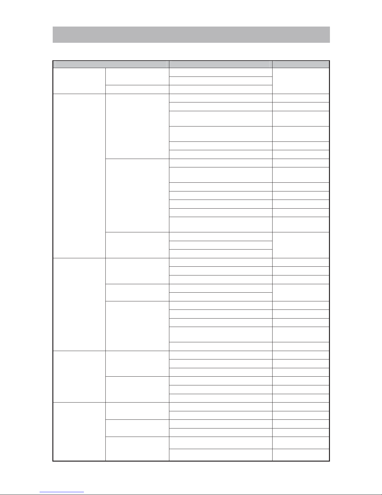
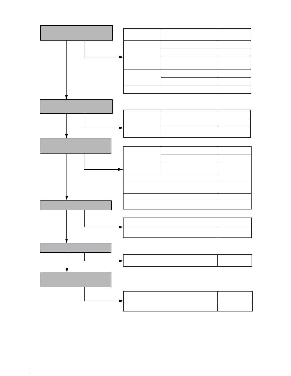
1. Troubleshooting and correction
Problem Cause Action
Starter grip cannot
be pulled.
Crank shaft does not
turn.
Seized piston ring
Disassemble and
replace.
Seized connecting rod bearing
Crank shaft turns. Defective starter
Engine does not
start.
Dry spark plug
Empty fuel tank Replenish with fuel.
Clogged fuel filter ass’y Clean or replace.
Folded or improperly connected or
damaged fuel pipe
Check or replace.
Defective air vent valve of
tank cap ass’y
Replace.
Clogged carburetor ass’y Clean.
Defective carburetor ass’y Check or replace.
No spark
Stained or defective spark plug Clean or replace.
Improperly connected high tension
cable and terminal
Check.
Damaged high tension cable Replace.
Improper air gap Adjust.
Defective coil Replace.
Defective stop switch Replace.
Improperly connected or damaged
internal wires
Check or replace.
No compression
Defective piston ring
Replace. Worn piston
Defective oil seal of crank chamber
Engine starts but
cannot continue
idling.
Weak sparking
Stained or defective spark plug Clean or replace.
Improper air gap Adjust.
Defective coil Replace.
Weak compression
Defective piston ring
Replace.
Defective oil seal of crank chamber
Proper sparking and
compression
Clogged carburetor ass’y Clean.
Defective carburetor ass’y Check or replace.
Clogged fuel filter ass’y Clean or replace.
Folded or improperly connected or
damaged fuel pipe
Check or replace.
Too low idling speed Adjust.
Engine starts and
accelerates but ...
Engine stops.
Clogged carburetor ass’y Clean.
Defective carburetor ass’y Check or replace.
Clogged fuel filter ass’y Clean or replace.
Accelerates
improperly. (Engine
does not rev up.)
Defective carburetor ass’y Check or replace.
Muffler clogged with carbon Clean.
Clogged element of air cleaner ass’y Clean.
Engine starts
but ...
Engine speed
fluctuates.
Clogged carburetor ass’y Clean.
Defective carburetor ass’y Check or replace.
Consumes excessive
fuel.
Defective carburetor ass’y Check or replace.
Clogged element of air cleaner ass’y Clean.
Cutting attachment
rotates at idling
speed.
Improper idling adjustment Adjust.
Worn clutch section Replace.
TROUBLESHOOTING GUIDE
Page 3
-2-
This section describes the troubleshooting and repair procedures for common phenomena that may occur
during engine brush cutter/grass trimmer operation. The procedures described here and in the
TROUBLESHOOTING GUIDE should be studied and referenced as needed to ensure efficient diagnosis
and the prompt repair of problems.
1. Precautions on maintenance, inspection and repair
• As the fuel used in the engine brush cutter/grass trimmer is highly flammable, carefully keep sources of
fire out of the area.
Start the engine as described below, and when confirming operation, be sure to use mixed fuel of
gasoline and two-cycle oil at a ratio of 25 to 50: 1.
• In case the engine section is disassembled, always be sure to replace gaskets and oil seals with new
ones prior to reassembly.
• Before starting disassembly and repair, thoroughly drain all fuel from the unit into a suitable container.
• Before disassembly, be sure to remove the cutting attachment to prevent damage to its cutting edge or
personal injury due to the cutting attachment.
• Always ensure that the engine has fully cooled down before attempting di sassembly.
• When starting, operating or performing maintenance on the unit, always avoid touching hot portions of
the muffler and other hot components, as well as the high tension cable or spark plug; otherwise, you
run the risk of a serious burn injury or electric shock.
• When a cutting attachment is mounted on the unit, carefully confirm that no one else is in the immediate
area before starting the engine.
• When repairing the unit indoors or in other protected areas, carefully ensure there is adequate
ventilation.
• Upon completing repair, carefully confirm that all screws, nuts and bolts are properly tightened, the
throttle trigger returns properly to the idling position when released, and the engine stops when you set
the stop switch to the STOP position.
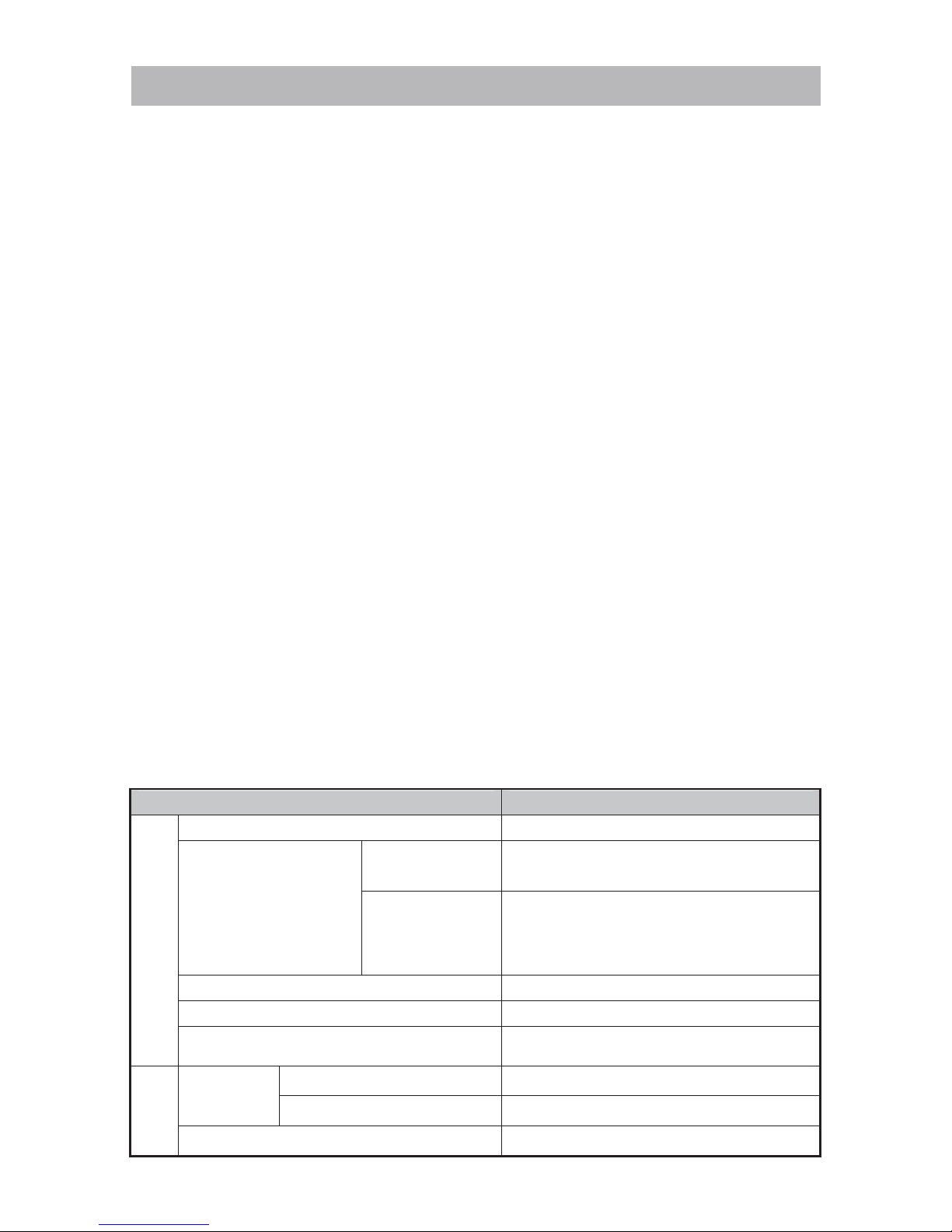
2. Inspection standards and spark plug replacement/adjustment
Use the table below as a handy guide during and after repair to meet inspection standards, and when
replacing or adjusting the spark plug.
Item Standard value
Inspection standards
Idling rotation speed 2,500 to 3,500 min
-1
No-load max. rotation
speed (after warming up)
CG 24EBSP(S)
CG 27EBSP(S)
[with cutter blade]
8,500 to 12,500 min
-1
CG 24EBSP/EBS
CG 24EBDP/EBD
CG 27EBSP/EBS
CG 27EBDP/EBD
[with nylon head]
8,200 min
-1
Clutch engagement 3,800 to 4,800 min
-1
Engine acceleration Smooth acceleration
Clearance between external circumference of
the flywheel and ignition coil
0.2 to 0.4 mm
Consumable
parts
Spark plug
Europe, Russia, Australia NGK BMR7A
Other regions CHAMPION CJ6
Gap between electrodes of the spark plug 0.6 to 0.7 mm
REPAIR GUIDE
Page 4
-3-
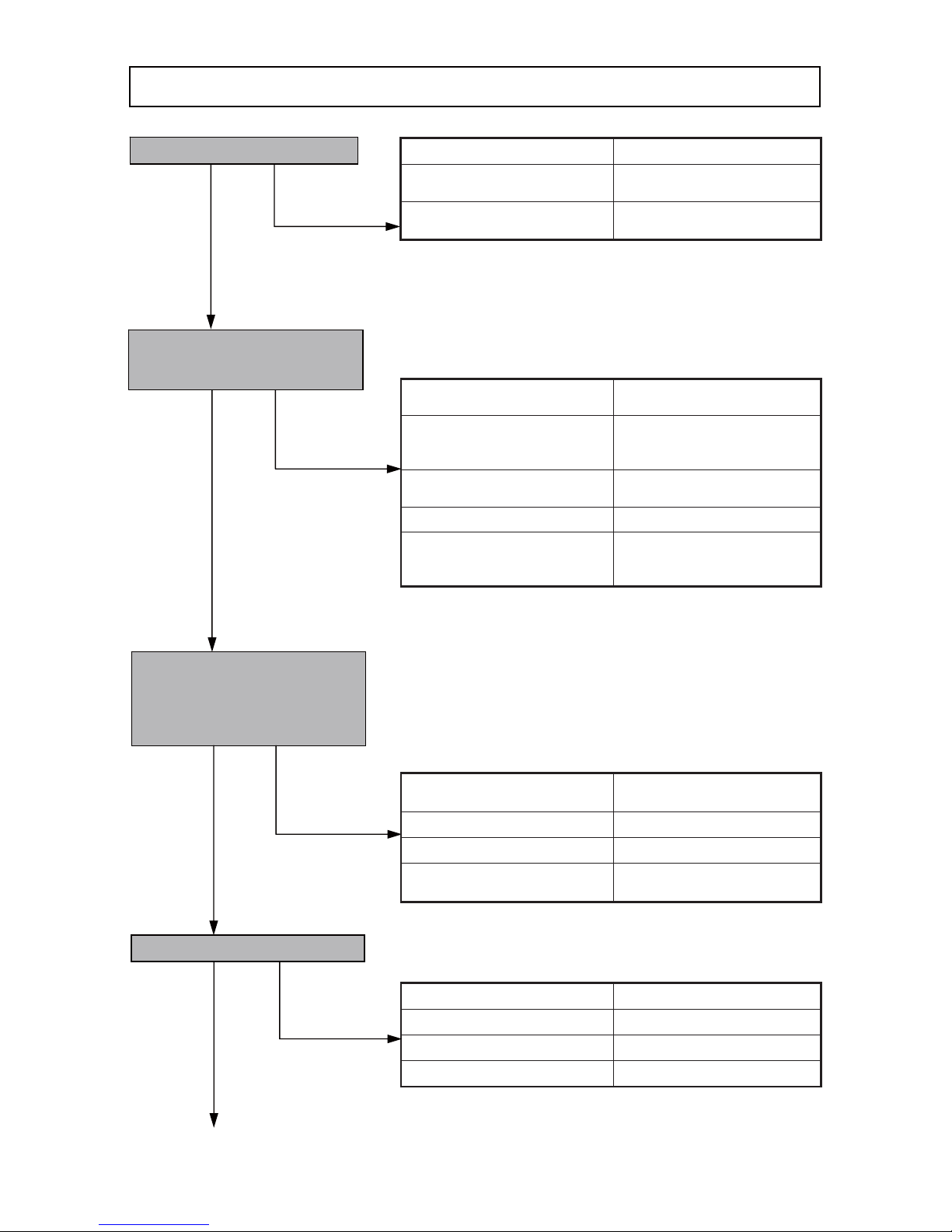
Pull the starter handle to perform
startup operation according to
page 5 and check whether the
spark plug is wet or dry. Is fuel
being properly supplied?
Is there compression?
Does the engine start?
Remove the spark plug and check
the spark according to page 5.
Is there a proper spark?
Fouled or defective spark plug Cleaning or replacement
Snapped or improper
connection of high tension
cable or internal wires
Inspection, repair or
replacement as necessary.
Improper high tension cable or
internal wires
Repair or replacement
Defective coil Replacement
Excessive clearance between
circumference of rotor fan and
coil
Readjustment
Clogged air vent valve of tank
cap ass’y
Replacement
Clogged carburetor Clea ning
Clogged fuel filter ass’y Cleaning or replacement
Defective primer pump of air
cleaner ass'y
Replacement or readjustment
Defective piston rings Cleaning or replacement
Worn piston rings Replacement
Worn piston Replacement
Worn or broken oil seals Replacement
Stop switch at “OFF” position
Set to “ON” position.
Empty primer pump
Push primer pump several
times.
Choke lever in closed position Turn to open position.
Repair flowchart
Yes
No
Yes
No
Yes
No
No Yes
Page 5
-4-
Weak spark
Fouled or defective spark
plug
Cleaning or
replacement
Improper fuel-air
mixture
Clogged fuel filter ass'y
Cleaning
Clogged carburetor
Cleaning
Defective carburetor ass'y
Inspection or
replacement
No compression
Worn piston rings
Replacement
Worn oil seals
Replacement
Broken magneto rotor ass'y key
Replacement
Improper fuel-air
mixture
Clogged fuel filter ass'y
Cleaning
Clogged carburetor
Cleaning
Defective carburetor ass'y
Inspection or
replacement
Improper fuel-air
mixture
Clogged fuel filter ass'y Cleaning
Clogged carburetor Cleaning
Defective carburetor ass'y
Inspection or
replacement
Clogged element of air cleaner ass'y Cleaning
Carbon clogged in muffler, cylinder or
exhaust vents
Cleaning
Defective ignition coil ass'y Replacement
Defective gasket or packing seal Replacement
Improper carburetor adjustment Readjustment
Defective carburetor ass'y
Inspection or
replacement
Defective carburetor ass'y
Inspection or
replacement
Idling adjustment of carburetor too high
Readjustment
Worn clutch section
Replacement
Yes
Does the engine accelerate when
throttle trigger is triggered?
Yes
No
Does the engine stop when the
choke lever is o
p
en?
Does the engine stop at idling?
Is fuel consumption excessive?
Does the cutting attachment
rotate at idling speed?
Engine starts. Does combustion
continue?
Yes
No
Yes
No
No
Yes
Yes
No
Page 6
-5-
[Bold] numbers in the description below correspond to item numbers in the Parts List and exploded
assembly diagram for the Model CG 24EBSP, (Bold) numbers co rrespond to those for the Model
CG 24EBDP, {Bold} numbers correspond to those for the Model CG 27EBSP, and <Bold> numbers
correspond to those for the Model CG 27EBDP as represe ntative models.
For other models, refer to the parts list of each model.
1. Starting the engine
(1) When the engine is cold:
(a) Set the stop switch to the ON position.
(b) Push the Priming Pump Comp. [43](43){44}<44> several times so that fuel flows through the Fuel
Pipe (Pink) [126](126){126}<126>.
(c) Set the choke lever to the CLOSED position “
”.
(d) Pull the recoil starter briskly, while being careful to grip the handle and not allowing it to snap back.
(e) When you hear the engine beginning to start, return the choke lever to the RUN position “
”.
(f) Pull the recoil starter briskly again.
NOTE: The marks “
”
and “” are indicated on Air Cleaner (A) Ass'y [46](46){47}<47>.
(2) When the engine is warm:
(a) Set the choke lever to the RUN position “
”.
(b) Set the stop switch to the ON position.
(c) Pull the recoil starter briskly, while being careful to grip the handle and not allowing it to snap back.
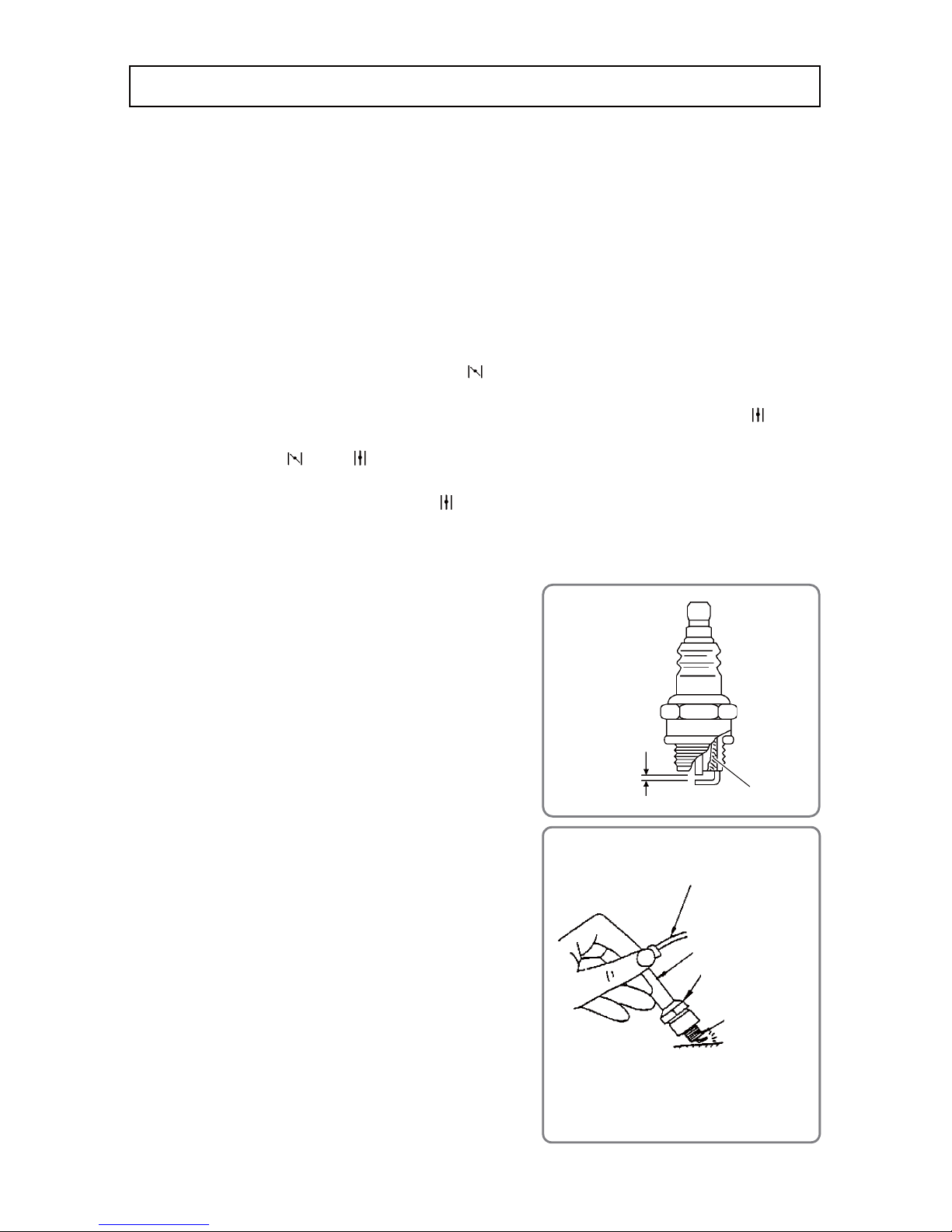
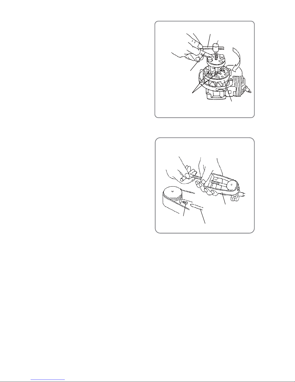
2. Checking for sparks of the spark plug
(1) Remove the Spark Plug Ass'y BMR7A [13](13){13}<13>
from the Cylinder [19](19){19}<19>. Use a wire brush to
thoroughly clean off any carbon on the electrodes of the
Spark Plug Ass'y BMR7A [13](13){13}<13>. If the gap
between the electrodes is improper, readjust it as shown
in the figure. If the electrodes are wet with fuel, use a
clean, soft cloth to thoroughly wipe the fuel off. Then
remove any residual fuel in the Cylinder [19](19){19}<19>
by following the procedure below.
(a) Hold the Spark Plug Ass'y BMR7A [13](13){13}<13>
away from the Cylinder [19](19){19}<19>.
(b) Face it down toward the spark plug mounting hole on
the Cylinder [19](19){19}<19>.
(c) Pull the starter grip a few times.
(2) Insert the Spark Plug Ass'y BMR7A [13](13){13}<13> into
the Plug Cap [120] (120){120}<120>.
While keeping the electrode portion of the Spark Plug
Ass'y BMR7A [13](13){13}<13> in contact with the metal
part of the engine but avoiding contact near the Spark
Plug Ass'y BMR7A [13](13){13}<13> mounting hole on
the Cylinder [19](19){19}<19>, pull the starter grip.
(3) When the Spark Plug Ass'y BMR7A [13](13){13}<13> is
functioning properly, there should be sparks from the
electrode portion, along with a crackling sound.
• Spark plug
Gap between
electrodes
(0.6 to 0.7 mm)
Remove carbon here.
High tension cable
Plug Cap
[120](120){120 }<120>
Spark Plug Ass'y
BMR7A
[13](13){13}<13>
Ignition sparks
Metal part of engine
(Avoid contact near the spark plug mounting
hole on the cylinder.)
* Wearing thick cotton gloves is recommended.
• Checking for sparks
Inspection and repairprocedures
Page 7
-6-
WARNING:
• When performing the procedure outlined above, touching an y metallic portions of the Spark Plu g
Ass'y BMR7A [13](13){13}<13> when pulling the starter grip will give you electric shock. Therefore,
be very careful in handling Spark Plug Ass'y BMR7A [13](13){13}<13>.
• Thoroughly wipe up any fuel around the Spark Plug Ass'y BMR7A [13](13){13}<13>, and confirm
that there is no danger of fire before checking the spark.
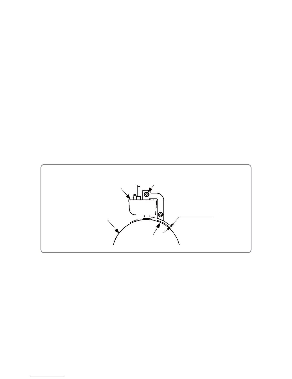
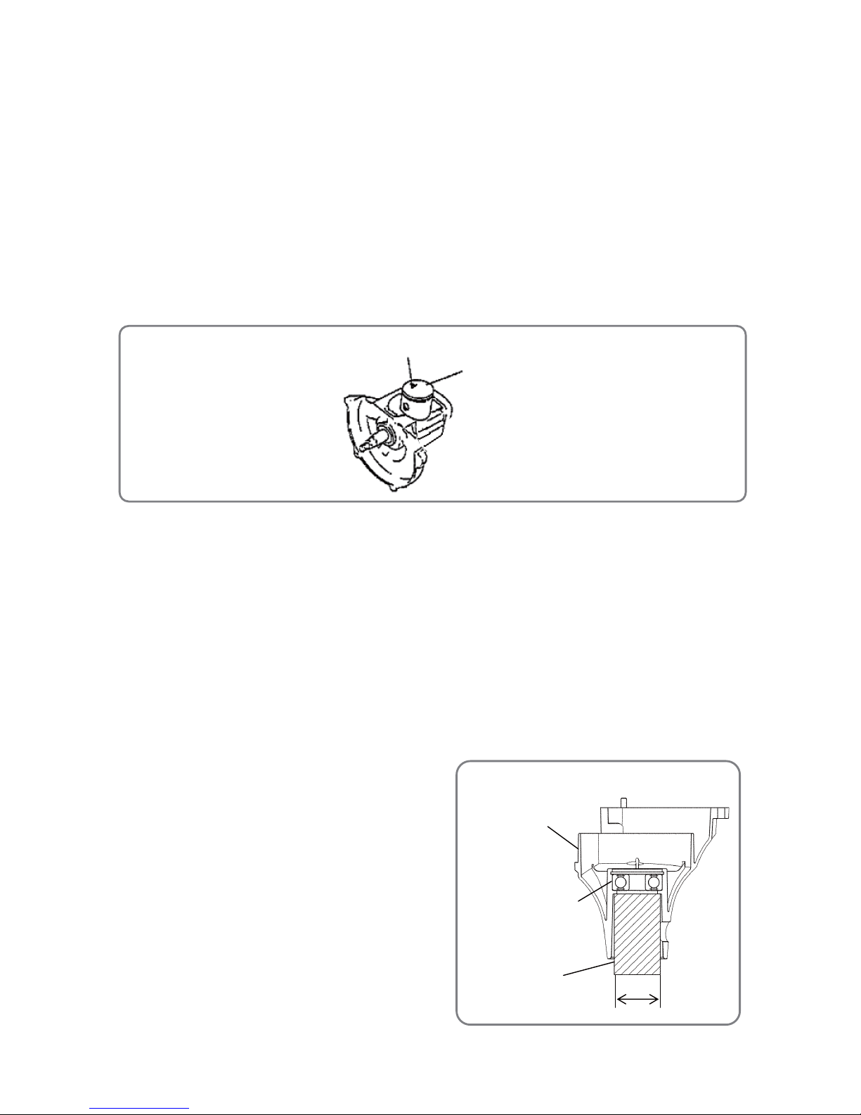
3. Adjusting the air gap (clearance) between the magneto rotor comp. perimeter
and ignition coil ass’y
(1) Remove the Muffler Cover [2](2){2}<2>, Cylinder Cover [9](9){8}<8> and Fan Case (A) [107](107)
{107}<107>.
(2) Loosen the two Hex. Socket Hd. Bolts (W/Washers) M4 x 18 [118](1 18){118}<118> so as to
temporarily secure the Ignition Coil Ass'y [119](119){119}<119>.
(3) Insert a thickness gauge between the magnetic steel portion around the perimeter of the Magneto
Rotor Ass'y [124](124)/Magneto Rotor Comp. {124}<124> and Ignition Coil Ass'y [119](119){ 119}
<119>, and then adjust the position of the Ignition Coil Ass'y [119](119){119}<119> to achieve a
clearance of 0.2 to 0.4 mm.
(4) Tighten the two Hex. Socket Hd. Bolts (W/Washers) M4 x 18 [118](118){118}<118> and remove the
thickness gauge.
(5) After securely tightening the Hex. Socket Hd. Bolts (W/Washers) M4 x 18 [118](118){118}<118>,
confirm that the clearance is between 0.2 mm and 0.4 mm.
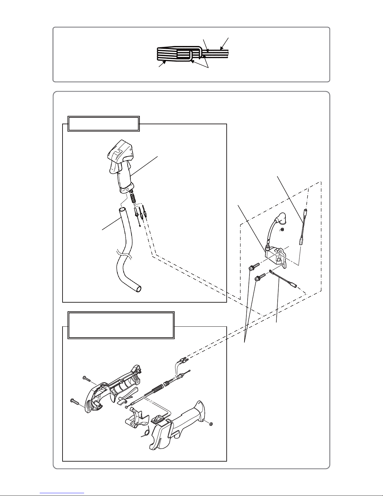
4. Wiring diagram
Wiring should be done as shown in the diagram below.
The Cord [122](122){122}<122> is connected to the connector on the Ignition Coil Ass'y [119](119){119}
<119>. The Earth Cord [123](123){123}<123> is fastened to the Ignition Coil Ass'y [119](119){119}<119>
with the Hex. Socket Hd. Bolts (W/Washers) M4 x 18 [118](118){118}<118>. The Cord [122](122){122}
<122> and the Earth Cord [123](123){123}<123> are connected to the terminal of Throttle Lever (B)
[151]{151} or Throttle Lever (A) Ass’y [99](99){99}<99>. Engage the needle tip of the Metal Fitting of Plug
Cap [120](120){120}<120> into the core wire of the high tension cable. Apply two-cycle oil to the cord
mounting hole of the Plug Cap [120](120){120}<120>, and then insert the high tension cable and the
Metal Fitting of Plug Cap [121](121){121}<121> into the hole. After mounting the parts, check for sparking
of the Spark Plug Ass'y BMR7A [13](13){13}<13> and continuity of the Metal Fitting of Plug Cap [121]
(121){121}<121>.
Ignition Coil Ass'y [119](119){119}<119>
Hex. Socket Hd. Bolt (W/Washers) M4 x 18 [118](118){118}<118>
Magneto Rotor Ass’y [124](124)
Magneto Rotor Comp. {124}<124>
Clearance between
0.2 mm and 0.4 mm
• Adjusting the clearance between the magneto rotor and ignition coil
Page 8
-7-
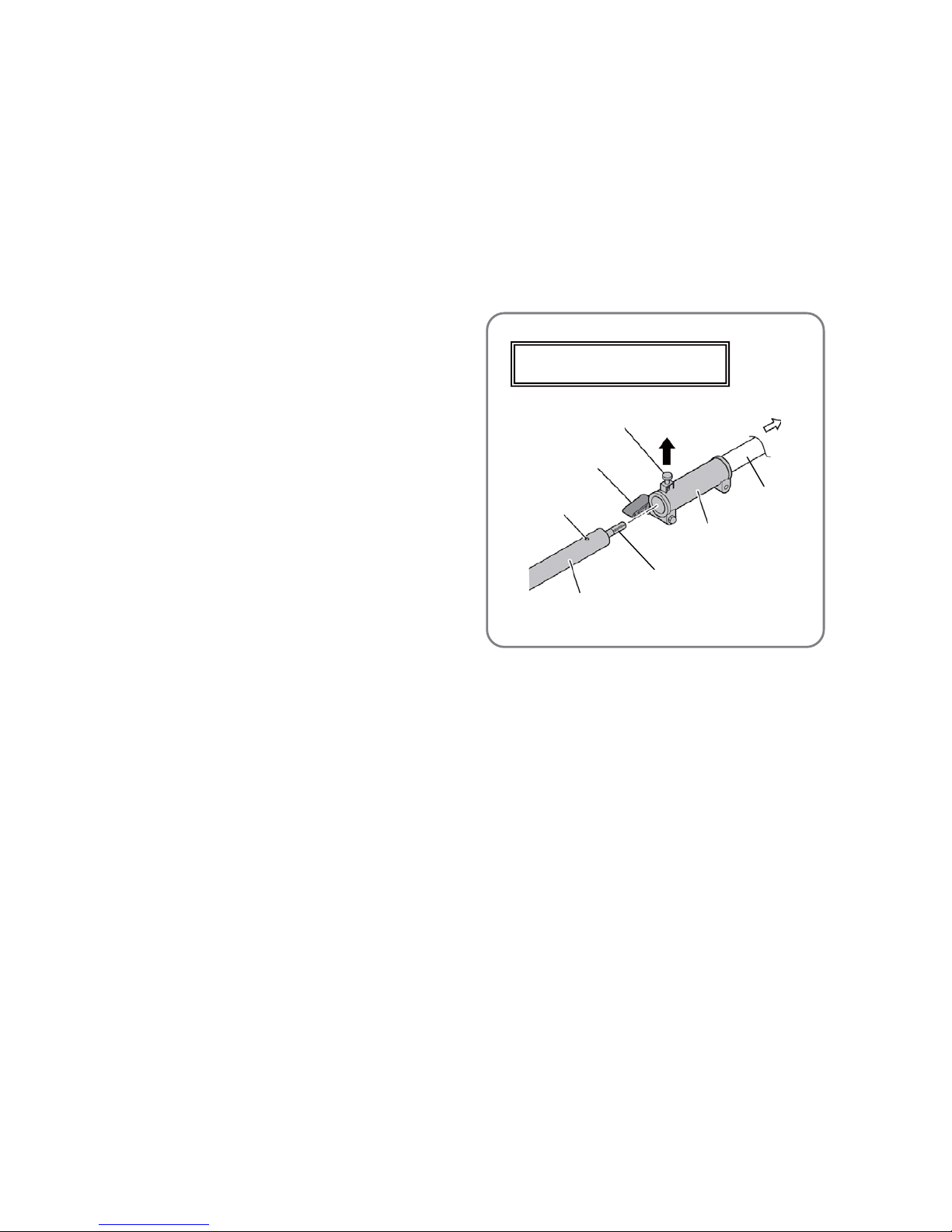
• Wiring diagram
Core wire
High tension cable
Engage the two tips of the Metal Fitting of Plug Cap
[121](121){121}<121> into the core wire.
Metal Fitting of Plug Cap
[121](121){121}<121>
• Metal fitting of plug cap
CG 24EBSP(S), CG 24EBS(S)
CG 27EBSP(S), CG 27EBS(S)
CG 24EBSP(SL), CG 24EBS(SL),
CG 24EBDP(SL)/(SLN), CG 24EBD(SL)/(SLN),
CG 27EBSP(SL), CG 27EBS(SL),
CG 27EBDP(SL)/(SLN), CG 27EBD(SL)/(SLN)
Cord [122](122){122}<122>
Earth Cord
[123](123){123}<123>
Hex. Socket Hd. Bolts (W/Washers)
M4 x 18 [118](118){118}<118>
Ignition Coil Ass’y
[119](119){119}<119>
Throttle Lever (B) [151]{151}
Throttle Lever (A) Ass’y [99](99){99}<99>
Handle (Right) [156]{156}
Page 9

-8-
5. Checking the fuel filter
Use a piece of wire to remove the Pump Filter Body Comp. [134](134){133}<133> from the fuel inlet of
Tank (B) [133](133){132}<132>. If the Pump Filter Body Comp. [134](134){133}<133> is stained, clean it
with gasoline. Remove the Pump Filter Body Comp. [134](134){133}<133> from the Fuel Pipe [125](125)
{125}<125>. Check whether the Pump Filter Body Comp. [134](134){133}<133> is clogged by breathing
through it. Replace the Pump Filter Body Comp. [134](134){133}<133> as necessary.
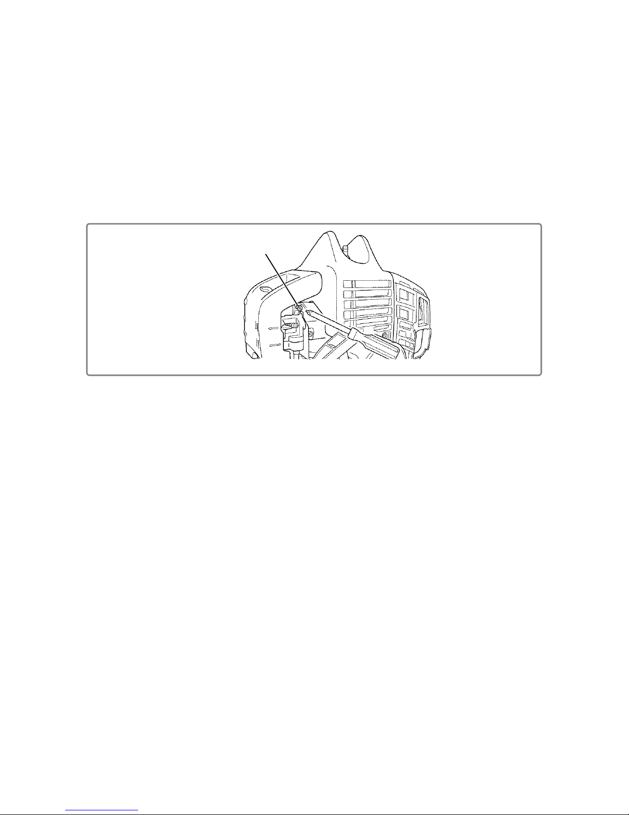
6. Cleaning the muffler and the cylinder
(1) Remove the Muffler Cover [2](2){2}<2>.
(2) Loosen the two Hex. Socket Hd. Bolts M6 x 65 [4](4){3}<3>, and then remove Muffler (B) [6](6){5}<5>
together with the Heat Protection Panel [7](7){6}<6>.
(3) Use a flat-blade screwdriver (precision) to scrape carbon off the exhaust port of Muffler (B) [6](6){5}
<5>. Close the exhaust port of the Cylinder [19](19){19}<19> with the Piston [49](49){50}<50>, and
then scrape carbon off the exhaust port.
NOTE: Do not scratch the inner wall surfaces of the Piston [49](49){50}<50> and the Cylinder
[19](19){19}<19>.
7. Cleaning the element
Open the Cleaner Cover [45](45){46}<46> of Air Cleaner (A) Ass'y [46](46){47}<47>. Remove the
Cleaner Element [44](44){45}<45> and clean it with compressor air. If the Cleaner Element [44](44){45}
<45> is heavily stained, clean it with gasoline and dry it well before reassembly.
8. Replacing the fuel pipe
If a crack is found on the Fuel Pipe L70 [41](41){42}<42>, Fuel Pipe [125](125){125}<125> or Fuel Pipe
(Pink) [126](126){126}<126>, replace the cracked pipe. Fit the Fuel Pipe [125](125){125}<125> equipped
with the Pump Filter Body Comp. [134](134){133}<133> into the socket at the bottom of the Carburetor
Ass'y WYC-36 [24](24)/WYC-37 {25}<25>/WYC-30*. Fit one end of the Fuel Pipe L70 [41](41){42}<42>
into the socket on the side of the Carburetor Ass’y WYC-36 [24](24)/WYC-37 {25}<25>/WYC-30, and fit
the other end of the Fuel Pipe L70 [41](41){42}<42> into the shorter socket on the Priming Pump Comp.
[43](43){44}<44> in Air Cleaner (A) Ass’y [46](46){47}<47>. Fit the Fuel Pipe (Pink) [126](126){126}
<126> into the longer socket on the Priming Pump Comp. [43](43){44}<44> in Air Cleaner (A) Ass’y [46]
(46){47}<47>.
*: Refer to the parts list of each model.
Page 10

-9-
• Replacing the fuel pipe
B
B
Tank (B)
[133](133){132}<132>
Return Grommet
[127](127){127}<127>
Fuel Pipe (Pink)
[126](126){126}<126>
Fuel Grommet
[130](130){130}<130>
Fuel Pipe
[125](125){125}<125>
Fuel Pipe L70
[41](41){42}<42>
Carburetor Ass'y
WYC-36 [24](24)/
WYC-37 {25}<25>/
WYC-30*
*: Refer to the parts
list of each model.
A
ir Cleaner (A) Ass'y
[46](46){47}<47>
Cleaner Cover
[45](45){46}<46>
Cleaner Element
[44](44){45}<45>
Priming Pump Comp.
[43](43){44}<44>
A
ir Cleaner Housing
[42](42){43}<43>
Pump Filter Body Comp.
[134](134){133}<133>
Page 11
-10-
• Idle adjust screw
Idle adjust screw
9. Checking and adjusting the carburetor ass’y
(1) Checking the Carburetor Ass'y WYC-36 [24](24)/WYC-37 {25}<25>/WYC-30
While disassembling the Carb ur e to r A s s' y W Y C -3 6 [24](24)/WYC-37 {25}<25>/WYC-30 , check its parts
for wear, deformation, and clogged holes. If dirt or dust is found on a part, clean it off or remove dust by
using an air blower. If a deformed or worn part is found, replace the part or entire Carburetor Ass'y
WYC-36 [24](24)/WYC-37 {25}<25>/WYC-30.
(2) Adjusting the Ca rburetor Ass'y WYC-36 [24](24)/WYC-37{25}<25>/WYC-30
Adjust the opening of the throttle valve during idling. Turning the idle adjust screw clockwise increases
engine speed; turning it counterclockwise reduces engine speed. If the cutting attachment rotates
during idling, reduce the speed so that the cutting attachment does not rotate. Note that excessively
low speed may cause the engine to stop during idling. In such case, increase the speed but do not
allow the cutting attachment to rotate.
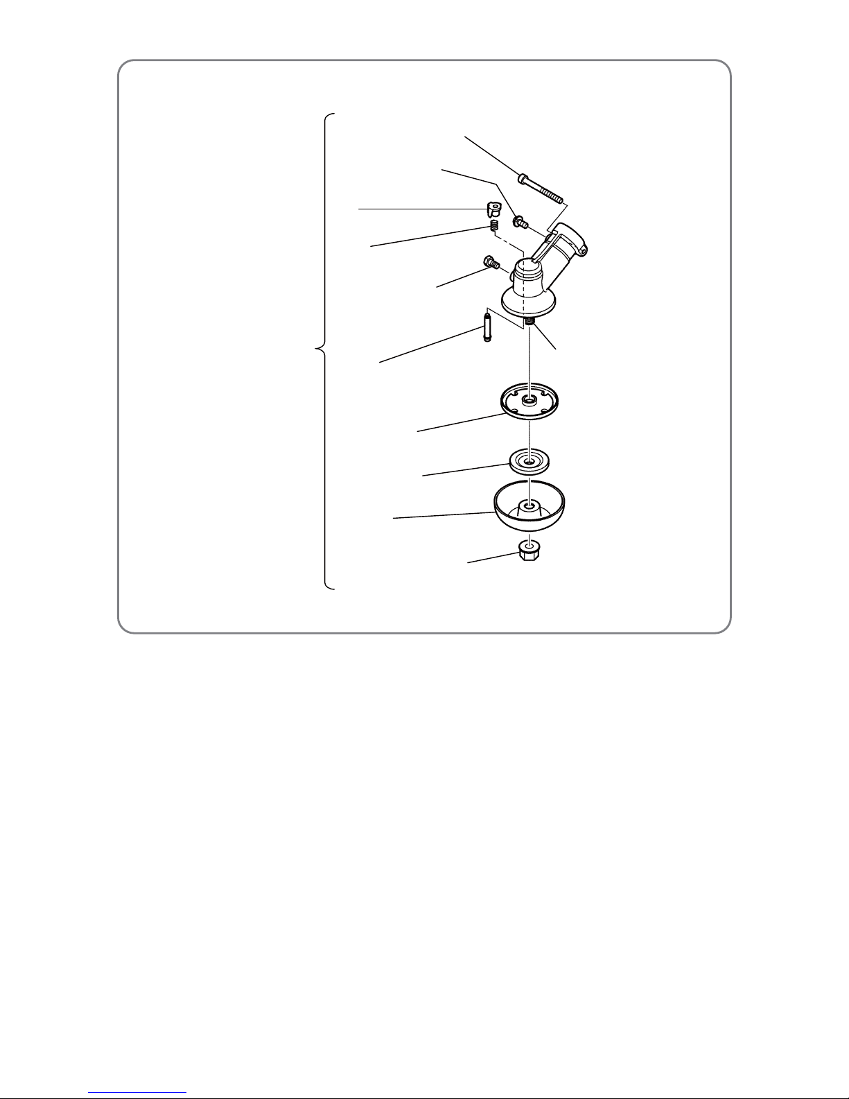
10. Cleaning the spindle lock
(1) Disassembly
(a) Loosen the U-Nut (Left Hand) M10 [170](180){170}<180> of the Gear Case Ass’y (4BB) [160](170)
{160}<170>, and then remove the Nut Cover [169](179){169}<179>, Cutter Holder (B) [168](178)
{168}<178>, and Cutter Holder (A) [167](177){167}<177>.
(b) Remove the press-fitted Cap [163](173){163}<173>, and then remove the Spring [164](174){164}
<174> and Lock Pin [166](176){166}<176>.
(2) Cleaning
(a) Thoroughly wipe off grease from the Lock Pin [166](176){166}<176> hole on the gear case and its
vicinity .
(b) Thoroughly wipe off grease from the Spring [164](174){164}<174> and Lock Pin [166](176){166}
<176>.
(c) Clean the groove (to be engaged with the Lock Pin [166](176){166}<176>) of Cutter Holder (A)
[167](177){167}<177>.
(3) Reassembly
(a) Apply grease to the Lock Pin [166](176){166}<176> and insert the pin into the gear case hole.
(b) Mount the Spring [164](174){164}<17 4> and press-fit the Cap [163](173){163 }<173 > tothe Lock Pin
[166](176){166}<176>. Be sure to use a new Cap [163](173){163}<173>.
(c) Push the Lock Pin [166](176){166}<176> and make sure that it returns to its home position.
Page 12
-11-
• Cleaning the spindle lock
U-Nut (Left Hand) M10
[170](180){170}<180>
Nut Cover
[169](179){169}<179>
Cutter Holder (B)
[168](178){168}<178>
Cutter Holder (A)
[167](177){167}<177>
Cap
[163](173){163}<173>
Spring
[164](174){164}<174>
Lock Pin
[166](176){166}<176>
Hex. Socket Hd. Bolt M5 x 30
[161](171){161}<171>
Screw 5 x 12/W.S
[162](172){162}<172>
Bolt (W/Plus) M6 x 8
[165](175){165}<175>
Gear Case Ass'y (4BB)
[160](170){160}<170>
Gear shaft D24
Page 13

-12-
1. Disassembly of the engine unit
(1) Separating the engine from the main pipe
Loosen the Hex. Socket Hd. Bolt (W/Sp. Washer) M5 x 12 [100](100){100}<100> and two Hex. Hole
Bolts 5 x 22/S [101](101){101}<101>, and then sep arate the engine from the shaft ass’y.
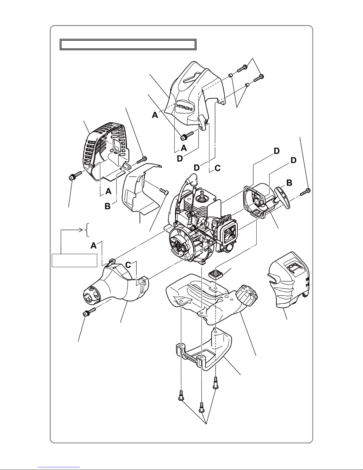
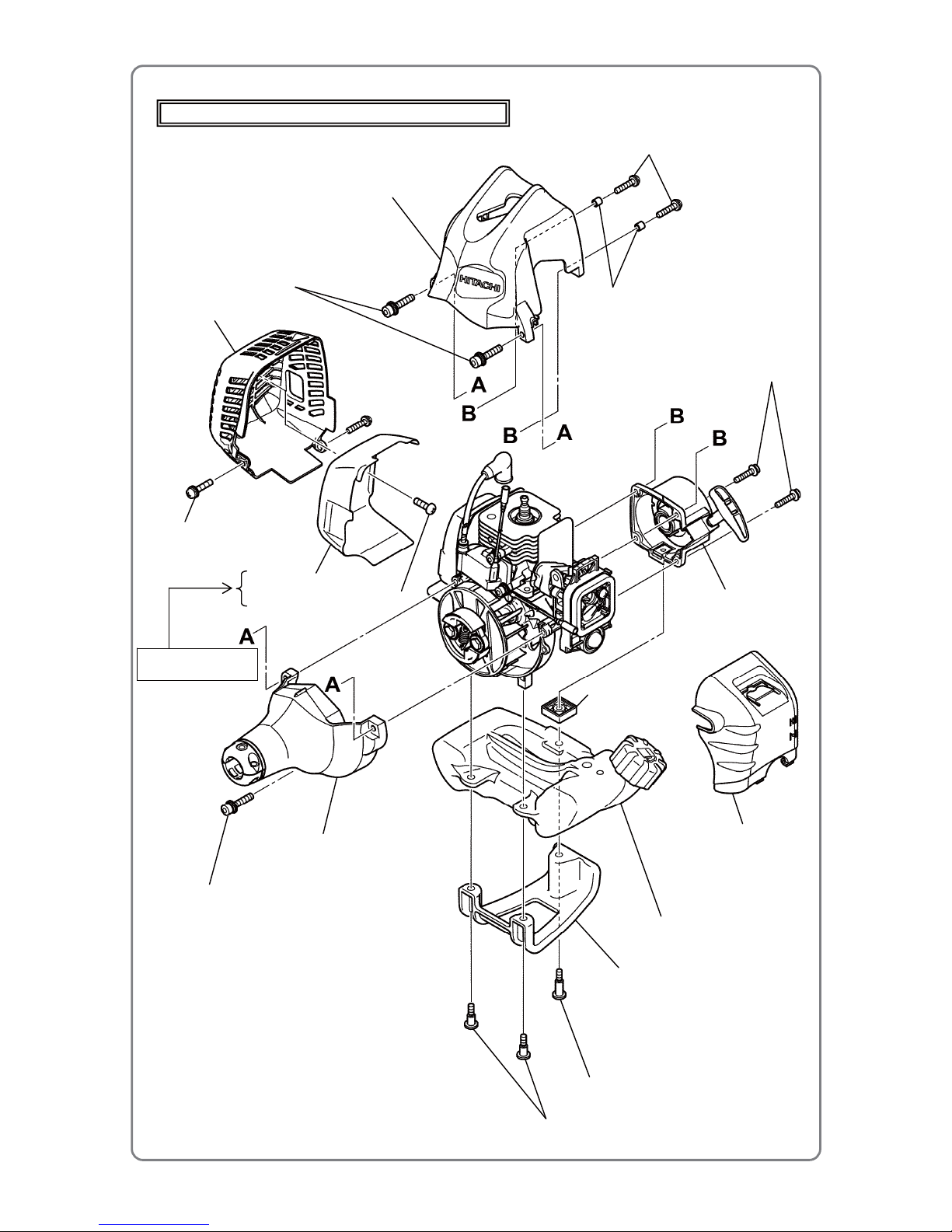
(2) Disassembly of the outer parts
(a) Disassembly of the muffler cover
Loosen the screws below to remove the Muffler Cover [2](2){2}<2>.
CG 24EBSP/CG 24EBDP: Seal Lock Hex. Socket Hd. Bolt M5 x 30 [1](1)
Hex. Socket Hd. Bolt (W/Flange) M4 x 18 [3](3)
CG 27EBSP/CG 27EBDP: Two Screws (W/Washers) M5 x 16 (Black) {1}<1>
(b) Disassembly of the cylinder cover
Loosen the screws below to remove the Cylinder Cover [9](9){8}<8>.
CG 24EBSP/CG 24EBDP: Seal Lock Hex. Socket Bolt (W/Washers) M5 [12](12)
Two Hex. Socket Hd. Bolts (W/Flange) M4 x 18 [3](3)
CG 27EBSP/CG 27EBDP: Two Seal Lock Hex. Socket Hd. Bolts M5 x 30 {12}<12>
Two Hex. Socket Hd. Bolts (W/Flange) M4 x 18 {10}<10>
NOTE: Be careful not to lose Collar (B) [10 ](10){9}<9>.
(c) Disassembly of the fan case
Loosen the screws below to remove Fan Case (A) [107](107){107}<107>.
CG 24EBSP/CG 24EBDP: Seal Lock Hex. Socket Bolt (W/Washers) M5 [12](12)
CG 27EBSP/CG 27EBDP: Seal Lock Hex. Socket Hd. Bolt M5 x 30 {12}<12>
(d) Disassembly of the tank
To remove Tank (B) [133](133){132}<132>, pull out the Fuel Pipe [125](125){125}<125> and Fuel
Pipe (Pink) [126](126){126}<126> from the Carburetor Ass'y WYC-36 [24](24)/WYC-37 {25}<25>
and Air Cleaner (A) Ass’y [46](46){47}<47>, and then loosen the screws below.
CG 24EBSP/CG 24EBDP: Three Bolts (W/Flange) L27.8 [137](137)
CG 27EBSP/CG 27EBDP: Two Flange Bolts {136}<136>
Bolt (W/Flange) L27.8 {137}<137>
(e) Disassembly of the recoil starter
To remove the Recoil Starter Body Ass'y [64](64){66}<66>, remove the Cylinder Cover [9](9){8}<8>
as described in (b) above, and then loosen the screws below.
CG 24EBSP/CG 24EBDP: Hex. Socket Hd. Bolts (W/Flange) M4 x 18 [3](3)
CG 27EBSP/CG 27EBDP: Two Hex. Socket Hd. Bolt s (W/Flange) M4 x 18 {10}<10>
Disassembly and reassembl
y
Page 14
-13-
• Disassembly of the outer parts (1)
Models CG 24EBSP, CG 24EBS, CG 24EBDP, and CG 24EBD
Tank (B) [133](133)
Muffler Cover [2](2)
Cylinder Cover [9](9)
Fan Case (A) [107](107)
Stand [136](136)
Recoil Starter Body Ass'y
[64](64)
Cleaner Cover [45](45)
Spacer [131](131)
Collar (B) [10](10)
Hex. Socket Hd. Bolts (W/Flange) M4 x 18 [3](3)
Seal Lock Hex. Socket
Hd. Bolt M5 x 30 [1](1)
Hex. Socket Hd. Bolt
(W/Flange) M4 x 18 [3](3)
Seal Lock Hex. Socket Bolt
(W/Washers) M5 [12](12)
Bolts (W/Flange) L27.8 [137](137)
Hex. Socket Hd. Bolt
(W/Flange) M4 x 18 [3](3)
Seal Lock Hex. Socket Bolt
(W/Washers) M5 [12](12)
Muffler Heat Cover [75](75)
Tapping Screw D4 x 10 [76](76)
For CG 24EBSP and
CG 24EBDP only
Page 15
-14-
• Disassembly of the outer parts (2)
Models CG 27EBSP, CG 27EBS, CG 27EBDP, and CG 27EBD
Tank (B) {132}<132>
Muffler Cover {2}<2>
Cylinder Cover {8}<8>
Fan Case (A) {107}<107>
Stand {135}<135>
Recoil Starter Body Ass'y
{66}<66>
Cleaner Cover {46}<46>
Spacer {131}<131>
Collar (B) {9}<9>
Hex. Socket Hd. Bolts (W/Flange) M4 x 18 {10}<10>
Seal Lock Hex. Socket Hd.
Bolts M5 x 30 {12}<12>
Bolt (W/Flange) L27.8 {137}<137>
Flange Bolts {136}<136>
Screws (W/Washers)
M5 x 16 (Black) {1}<1>
Hex. Socket Hd. Bolts
(W/Flange) M4 x 18 {10}<10>
Seal Lock Hex. Socket Hd. Bolt M5 x 30 {12}<12>
Muffler Heat Cover {77}<77>
Tapping Screw D4 x 10 {78}<78>
For CG 27EBSP and
CG 27EBDP only
Page 16

-15-
(3) Removing the muffler
Loosen the two Hex. Socket Hd. Bolts M6 x 65**[4](4){3}<3>, and then remove Muffler (B) [6](6){5}
<5> and the Heat Protection Panel [7](7){6}<6> together.
**: For the Models CG 24EBS, CG 24EBD, CG 27EBS and CG 27EBD, loosen the hex. socket hd.
bolts M6 x 55.
(4) Removing the spark plug
Remove the Plug Cap [120](120){120}<120> from the Spark Plug Ass’y BMR7A [13](13){13}<13>, and
then remove the Spark Plug Ass'y BMR7A [13](13){13}<13>.
(5) Removing the air cleaner ass’y, carburetor ass’y, and carburetor insulator
Open the Cleaner Cover [45](45){46}<46> of Air Cleaner (A) Ass’y [46](46){47}<47>, loosen the two
Machine Screws (W/Washers) M5 x 60 (Black) [40](40){41}<41>, and then remove Air Cleaner (A)
Ass’y [46](46){47}<47>, Carburetor Ass’y WYC-36 [24](24)/WYC-37 {25}<25>/WYC-30, and
Carburetor Packing [22](22){23}<23> together. Loosen the two Seal Lock Hex. Socket Bolts
(W/Washer) M5 [12](12){22}<22>, and then remove the Carburetor Insulator [21](21){21}<21> and
Intake Packing [20](20){20}<20> together.
(6) Removing the fan case and clutch shaft
Place Fan Case (A) [107](107){107}<107> so that its surface facing the crank case is positioned
downward, and then remove the Retaining Ring for D12 Shaft [106](106){106}<106>. Use a hand
press or other tool to slowly push the shaft of the Clutch Shaft [110](110){110}<110> and remove it
without damaging the ball bearing of Fan Case (A) [107](107){107}<107>. Next, remove the Retaining
Ring 37 mm [109](109){109}<109> and slowly push the Ball Bearing 6301ZZC3 [108](108){108}<108>
out from the front end of Fan Case (A) [107](107){107}<107>.
(7) Removing the ignition coil and spark plug cap
Loosen the two Hex. Socket Hd. Bolts (W/Washers) M4 x 18 [118](118){118}<118>, and then remove
the Ignition Coil Ass’y [119](119){119}<119>. Add a drop of oil into the hole on the Spark Plug Ass’y
BMR7A [13](13){13}<13> side, move the high-voltage wire back and forth to spread oil inside the hole,
and then slowly pull out the Plug Cap [120](120){120}<120>, while being careful not to extend the
Metal Fitting of Plug Cap [121](121){121}<121>.
(8) Removing the clutch ass’y and starter pulley
In order to lock the Crank Shaft Comp. [58](58)/Crank Shaft {59}<59>, first insert the rope of the recoil
starter or other rope into the Spark Plug Ass’y BMR7A [13](13){13}<13> mounting hole on the Cylinder
[19](19){19}<19>, and then turn the Magneto Rotor Ass’y
[124](124) and Magneto Rotor Comp.
{124}<124> counterclockwise until the Piston [49](49){50}<50> is locked at top dead center. Next,
loosen the two Step Bolts [111](111){111}<111> and remove the Clutch [114](114){114}<114>. To
remove the Starter Pulley Ass’y [60](60){62}<62>, lock the Crank Shaft Comp. [58](58)/Crank Shaft
{59}<59>, and then use a plastic hammer to lightly strike the Starter Pulley Ass’y [60](60){62}<62> to
turn it counterclockwise.
NOTE: Use a clean rope to lock the crank shaft. Also be careful not to leave cut pieces of rope
inside the Cylinder [19](19){19}<19>.
Page 17
-16-
Magneto Rotor Ass’y [124](124)/
Magneto Rotor Comp. {124}<124>
J-357 (center bolt)
Hex. socket hd. bolt M4
Pin pullout bolt
J-359 jig
(piston pin extraction
tool ass’y)
(9) Removing the magneto rotor
• Use a 13-mm socket wrench to remove the
Flywheel Nut [116](116){116}<116>.
• With the screw end face of the Crank Shaft
Comp. [58](58)/Crank Shaft {59}<59> made
flush with the upper face of a commercially
available M8 nut, rotate the J-363 jig (8 x
120 handle) in the arrow direction and
tighten the J-357 jig (center bolt) as shown
in the illustration on the right. Then remove
the Magneto Rotor Ass’y [124](124)/
Magneto Rotor Comp. {124}<124>.
(10) Removing the cylinder
Loosen the four Hex. Socket Hd. Bolts
(W/Sp. Washer) M5 x 18 [8](8)/Hex. Socket
Bolts M5 x 20 {7}<7>, and then slowly pull
out the Cylinder [19](19){19}<19>.
(11) Removing the piston and piston ring
• Remove the Piston Rings [48](48){49}<49>
while expanding the closed gap of the rings.
As the Piston Rings [48](48){49}<49> are
cast-iron parts, do not forcibly expand them.
Doing so may break the rings.
• Remove the two Cir Clips [50](50){51}<51>
with long-nose pliers.
• Insert a hex. socket hd. bolt M4 into the
pushing side of the Piston Pin [52](52){52}
<52>, and then turn the pin pullout bolt of
the J-359 jig (piston pin extraction tool
ass’y) clockwise to pull out the Piston Pin
[52](52){52}<52>.
CAUTION: Do not scratch the Piston [49]
(49){50}<50>.
(12) Removing the crank case ass’y
Loosen the four Hex. Socket Hd. Bolts (W/Sp. Washer) M5 x 18 [8](8){53}<53>, remove the Crank
Case Ass’y [53](53), Crank Case (A) Ass’y {60}<60> and Crank Case (B) Ass’y {54}<54> by using a
wooden hammer to lightly strike the Crank Shaft Comp. [58](58)/Crank Shaft {59}<59>, and then
remove the Crank Shaft Comp. [58](58)/Crank Shaft {59}<59>.
(13) Removing the muffler heat cover
Loosen the Tapping Screw D4 x 10 [76](76){78}<78> and then remove the Muffler Heat Cover [75]
(75){77}<77>.
• Removing the magneto rotor
J-363 jig (8 x 120 handle)
J-356 jig
(complete rotor
extraction tool
)
J-365 jig
(stepped bolt 5 mm)
• Removing the piston
Page 18
-17-
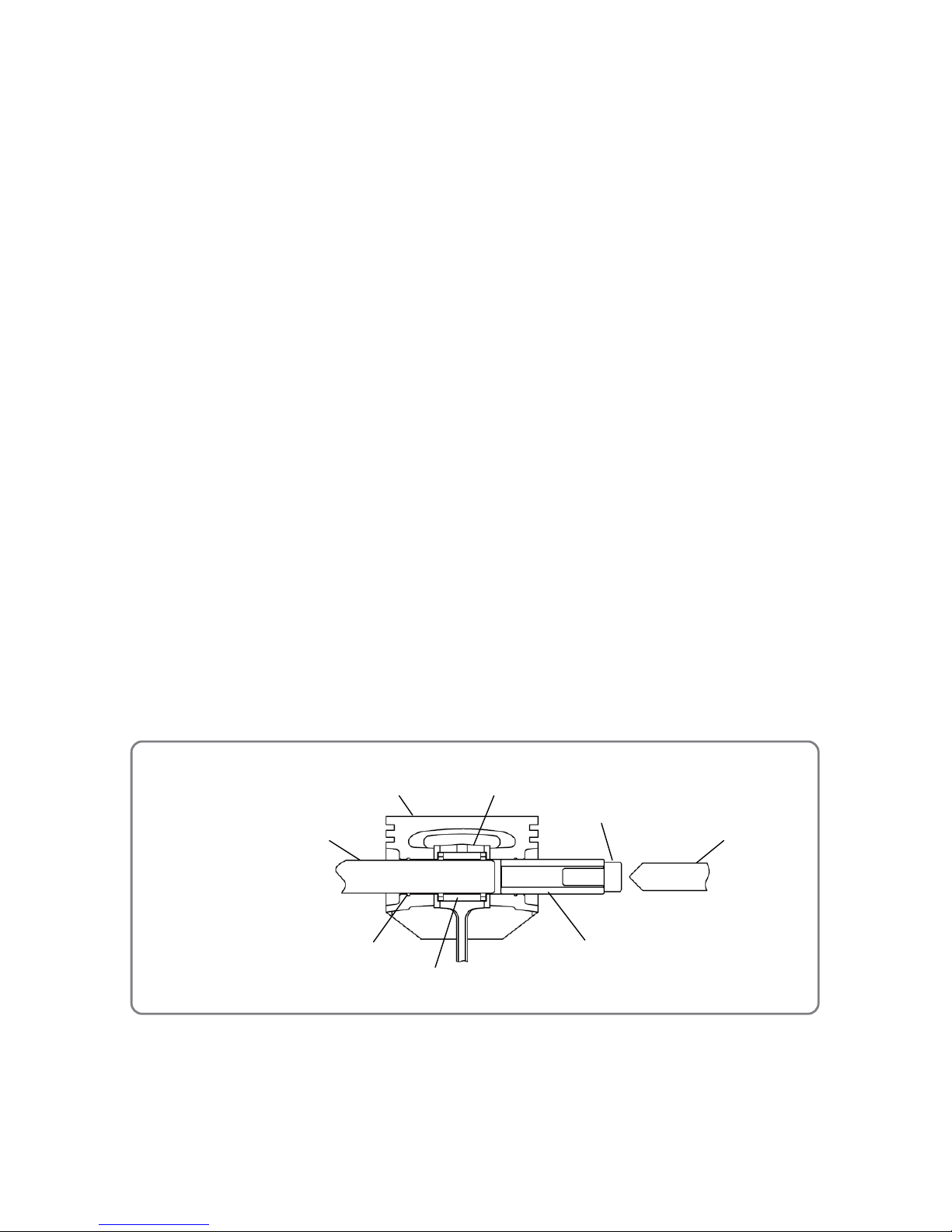
• Mounting the piston
Piston [49](49){50}<50>
Pin pullout bolt
Piston Pin [52](52){52}<52>
Hex. socket hd. bolt M4
Round bar 7.8 mm in diameter
(e.g., borer 8 mm in diameter)
Needle bearing (A)
(Crank Shaft Comp. [58](58)/Crank Shaft {59}<59>)
Cir clip mounting groove
Connecting rod small end
2. Reassembly of the engine unit
(1) Removing carbon
Before reassembling the engine, remove carbon from the head of the Piston [49](49){50}<50>, the
exhaust port of the Cylinder [19](19){19}<19>, and inside the combustion chamber. If the Piston Rings
[48](48){49}<49> fitted in the ring groove on the Piston [49](49){50}<50> cannot move smoothly,
carefully wipe off carbon from the ring groove and side surface of the Piston Rings [48](48){49}<49>.
During cleaning, be careful not to damage the surfaces of the Cylinder [19](19){19}<19> and Piston
[49](49){50}<50>. Also remove carbon from the intake and exhaust ports of Muffler (B) [6](6){5}<5>.
(2) Cleaning the parts
Be sure to thoroughly clean the Crank Shaft Comp. [58](58)/Crank Shaft {59}<59>, Piston [49](49)
{50}<50>, and Cylinder [19](19){19}<19> with gasoline.
(3) Mounting the piston and piston ring
• Insert the Piston Pin [52](52){52}<52> by following the procedure below. (See the figure below.)
(a) Insert the Piston Pin [52](52){52}<52> into the Piston [49](49){50}<50> by about 7 mm.
CAUTION: Do not tilt the Piston Pin [52](52){52}<52>.
(b) Set the J-359 jig (piston pin extraction tool ass’y) to the Piston [49](49){50}<50>, and then set a
hex. socket hd. bolt M4 into the pushing side of the Piston Pin [52](52){52}<52>.
(c) Set the needle bearing to the connecting rod small end, and then cover it with the Piston [49](49)
{50}<50>. (Align the triangular arrow on top of the Piston [49](49){50}<50> with the direction of the
exhaust port of the Cylinder [19](19){19}<19>.) Insert a round bar about 7.8 mm in diameter (e.g.,
borer 8 mm in diameter) into the Piston [49](49){50}<50> opposite the side where the Piston Pin
[52](52){52}<52> is inserted, in order to prevent needle bearing misalignment.
(d) With the round bar 7.8 mm in diameter inserted, turn the pin pullout bolt of the J-359 jig (piston pin
extraction tool ass’y) clockwise, and then push in the Piston Pin [52](52){52}<52> just before the
cir clip mounting groove of the Piston [49](49){50}<50>.
• Use long-nose pliers to fit the tip of the two Cir Clips [50](50){51}<51> into the groove on the Piston
[49](49){50}<50>, and then turn it until the Cir Clips [50](50){51}<51> are completely mounted.
• Align the opening of the two Piston Rings [48](48){49}<49> with the knock pin of the Piston [49](49)
{50}<50>.
• After mounting the Piston [49](49){50}<50>, apply a few drops of 2-cycle oil to the needle bearing.
Page 19
-18-
Arrow
Piston [49](49){50}<50>
(4) Reassembling the crank case ass’y, piston, and cylinder
When press-fitting Oil Seal TB 12227 [55](55){56}<56> into the Crank Case Ass’y [53](53), Crank
Case (A) Ass’y {60}<60> and Crank Case (B) Ass’y {54}<54>, position the pressurizing spring inside,
and then fill the gap between the lips with Multemp PS No. 2 (product of Kyodo Yushi Co., Ltd.).
Dispose of the oil seal removed at disassembly, and always use a new oil seal. Before mounting the
Cylinder [19](19){19}<19>, be sure to apply two-cycle engine oil to the Ball Bearing 6001 C3 [56](56)
{57}<57>, the large and small bearings at the ends of the connecting rod, the Piston Rings [48](48)
{49}<49>, and the inner surface of the Cylinder [19](19){19}<19>. When mounting the Piston [49](49)
{50}<50>, position it so that the exhaust mark (arrow) on top of the piston points to the muffler. When
mounting the Cylinder [19](19){19}<19>, correctly align the closed gap of the Piston Rings [48](48)
{49}<49> with the lock pin at the groove on the Piston [49](49){50}<50>, and the Cylinder [19](19){19}
<19> with the Piston [49](49){50}<50>. Otherwise, the Piston Rings [48](48){49}<49> may be easily
damaged.
(5) Mounting the magneto rotor
• Models CG 24EBSP, CG 24EBS, CG 24EBDP, and CG 24EBD
Insert the Woodruff Key 3 x 13 x 4.5 [51](51) in the key groove on the Crank Shaft Comp. [58](58), and
mount it into the key groove at the center hole of the Magneto Rotor Ass'y [124](124).
• Models CG 27EBSP, CG 27EBS, CG 27EBDP, and CG 27EBD
Mount the Magneto Rotor Comp. {124}<124> with the integral key at the center hole of the Magneto
Rotor Comp. {124}<124> aligned with the key groove on the Crank Shaft {59}<59>.
(6) Reassembling the carburetor ass’y
When reassembling Carburetor Ass'y WYC-36 [24](24)/WYC-37 {25}<25>/WYC-30, align the pulsed
holes on the Carburetor Packing [22](22){23}<23> and Intake Packing [20](20){20}<20> with those on
the Cylinder [19](19){19}<19> and Carburetor Ass’y WYC-36 [24](24)/WYC-37 {25}<25>/WYC-30.
(7) Mounting the fan case
Insert a press-fitting jig fit for the pipe insertion hole
of Fan Case (A) [107](107){107}<107> and push
the outer ring of the Ball Bearing 6301ZZC3 [108]
(108){108}<108> with the press-fitting jig from the
engine side. Then mount the Retaining Ring 37 mm
[109](109){109}<109>.
While holding the inner ring of the ball bearing in
Fan Case (A) [107](107){107}<107>, press-fit the
Clutch Shaft [110](110){110}<110> and then attach
the Retaining Ring for D12 Shaft [106](106){106}
<106>.
• Mounting the ball bearing
• Orientation of the piston
Fan Case (A)
[107](107){107}<107>
Ball Bearing 6301ZZC3
[108](108){108}<108>
BB press-fitting jig
D36
Page 20
-19-
(8) Mounting the muffler heat cover
Put the Muffler Heat Cover [75](75){77}<77> in the Muffler Cover [2](2){2}<2>. Align the screw holes
and tighten the Tapping Screw D4 x 10 [76](76){78}<78>. Check that the Muffler Heat Cover [75](75)
{77}<77> contacts the inner wall of the Muffler Cover [2](2){2}<2> and there is no rattling.
3. Disassembly of the shaft unit
• Models CG 24EBSP, CG 24EBS, CG 27EBSP, and CG 27EBS
(1) Pull out the Drive Shaft [186]{186} from the Main Pipe [185]{185}.
(2) Loosen the Screw 5 x 12/W.S [162]{162} and Hex. Socket Hd. Bolt M5 x 30 [161]{161}, and then
detach the Gear Case Ass’y (4BB) [160]{160} from the Main Pipe [185]{185}.
• Models CG 24EBDP, CG 24EBD, CG 27EBDP, and CG 27EBD
(1) Loosen the Handle Knob (152)<152>, pull the
lock pin, and then pull out the attachment
ass’y.
(2) Loosen the Hex. Socket Hd. Bolt M5 x 12
(154)<154> and Hex. Socket Hd. Bolt
(W/Button) M6 (156)<156>, and then remove
the Joint Case (169)<169> from Main Pipe (A)
(163)<163>. Pull out Drive Shaft (A) (165)
<165>.
(3) Loosen the Screw 5 x 12/W.S (172)<172> and
Hex. Socket Hd. Bolt M5 x 30 (171)<171>,and
then remove the Gear Case Ass’y (4BB) (170)
<170> of the attachment ass’y from Main Pipe
(A) (195)<195>. Pull out the Drive Shaft B
783L (196)<196> from the Gear Case Ass’y
(4BB) (170)<170> side.
4. Reassembly of the shaft unit
• Models CG 24EBSP, CG 24EBS, CG 27EBSP, and CG 27EBS
(1) Mounting the drive shaft
Wipe off dirty grease from the Drive Shaft [186]{186} and apply a thin coat of “Molub-Alloy 777”
grease to the shaft. Then insert the drive shaft into the Main Pipe [185]{185}.
(2) Mounting the gear case
Fully insert the Main Pipe [185]{185} into the main pipe insertion hole on the Gear Case Ass’y (4BB)
[160]{160} until it contacts the end. Align the hole on the side of the Main Pipe [185]{185} with the
M5 screw hole on the side of the Gear Case Ass’y (4BB) [160]{160}. Firmly tighten the Screw 5 x
12/W.S [162]{162} while confirming that it does not touch the Main Pipe [185]{185}. Tighten the Hex.
Socket Hd. Bolt M5 x 30 [161]{161}. Finally, make sure the Drive Shaft [186]{186} is completely put
in the pinion. When the drive shaft is completely put in the pinion, the gear shaft D24 of the Gear
Case Ass’y (4BB) [160]{160} rotates when rotating the Drive Shaft [186]{186} projected from the
side edge of the engine of the Main Pipe [185]{185}.
• Models CG 24EBDP, CG 24EBD, CG 27EBDP, and CG 27EBD
(1) Reassembling the attachment ass’y
When press-fitting the Bushing (192)<192> to the Drive Shaft B 783L (196)<196>, press-fit it to 50
mm from the spline end of the Drive Shaft B 783L (196)<196>.
Wipe off dirty grease from the Drive Shaft B 783L (196)<196> after press-fitting the Bushing (192)
<192> and apply a thin coat of “Molub-Alloy 777” grease to the shaft. Then insert the drive shaft into
Main Pipe (A) (195)<195>.
Fully insert Main Pipe (A) (195)<195> into the main pipe (A) insertion hole on the Gear Case Ass’y
• Disassembly of the shaft
Models CG 24EBDP, CG 24EBD,
CG 27EBDP, and CG 27EBD
Lock pin
Handle Knob (152)<152>
Joint Case
(169)<169>
A
ttachment ass’y
(Main Pipe (A) (195)<195>)
Location hole
Engine side
Main Pipe (A)
(163)<163>
Drive Shaft B 783L (196)<196>
Page 21

-20-
(4BB) (170)<170> until it contacts the end. Align the hole on the side of Main Pipe (A) (195)<195>
with the M5 screw hole on the side of the Gear Case Ass’y (4BB) (170)<170>. Firmly tighten Screw
5 x 12/W.S (172)<172> while confirming that it does not touch Main Pipe (A) (195)<195>. Tighten
the Hex. Socket Hd. Bolt M5 x 30 (171)<171>. Finally, make sure the Drive Shaft B 783L (196)<196>
is completely put in the pinion. When the drive shaft is completely put in the pinion, the gear shaft
D24 of the Gear Case Ass’y (4BB) (170)<170> rotates when rotating the Drive Shaft B 783L
(196)<196> projected from the side edge of the engine of Main Pipe (A) (195)<195>.
(2) Reassembling the shaft unit on the engine side
Wipe off dirty grease from Drive Shaft (A) (165)<165> after mounting the Retaining Ring for D10
Shaft (162)<162> and apply a thin coat of “Molub-Alloy 777” grease to the shaft. Then insert the
drive shaft into Main Pipe (A) (163)<163>.
Mount the Pulley Washer (161)<161>, Spacer (160)<160> and Spacer 1.6 (159)<159> to Main Pipe
(A) (163)<163> and insert Main Pipe (A) (163)<163> into the Joint Case (169)<169>. At this time,
align the hole on the side of Main Pipe (A) (163)<163> with the M5 screw hole on the side of the
Joint Case (169)<169>. Firmly tighten the Hex. Socket Hd. Bolt M5 x 12 (154)<154> while
confirming that it does not touch Main Pipe (A) (163)<163>. Tighten the Hex. Socket Hd. Bolt
(W/Button) M6 (156)<156>.
(3) Reassembling the attachment ass’y
Insert Main Pipe (A) (195)<195> into the Joint Case (169)<169> while pulling up the lock pin. Align
the lock pin with the hole on the upper surface of Main Pipe (A) (195)<195> and release the lock pin.
Make sure the lock pin is completely in the hole on the upper surface of Main Pipe (A) (195)<195>.
Then firmly tighten the Handle Knob (152)<152>.
Page 22
-21-
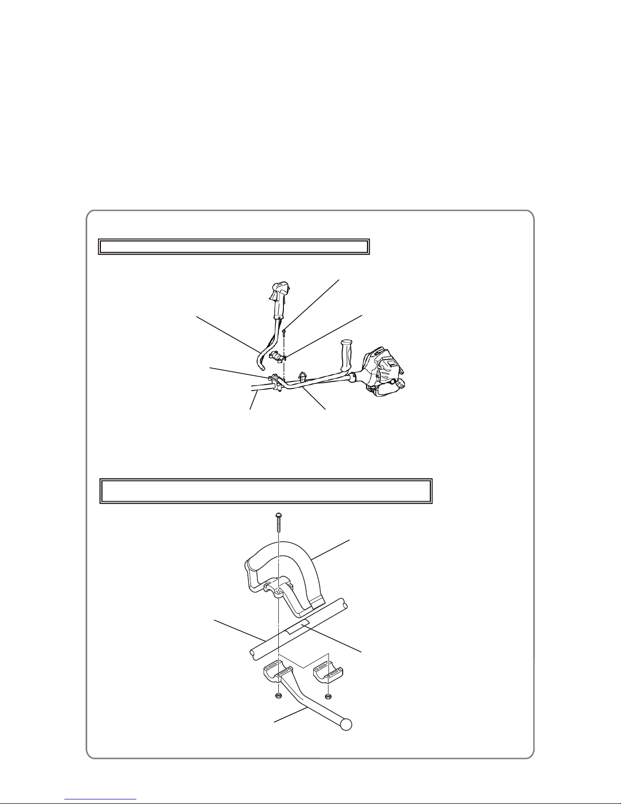
Main Pipe [185]{185}/
Main Pipe (A) (163)<163>
Level Mark [183](164){183}<164>
Loop Handle (W/Barrier) [152](167){152}<167>
or loop handle without a barrier
For details, see the parts list of the relevant model.
Barrier
Main Pipe [185]{185}
Handle (Right) [156]{156}
Handle (Left) [155]{155}
Handle Holder (A) [154]{154}
Hex. Hole Bolt M5 x 25/S [153]{153}
Handle Holder (B) [157]{157}
5. Mounting the handle
• Models CG 24EBSP(S), CG 24EBS(S), CG 27EBSP(S), and CG 27EBS(S)
Place the Handle (Right) [156]{156} and Handle (Left) [155]{155} on Handle Holder (B) [157]{157}
attached to the Main Pipe [185]{185}, and then place Handle Holder (A) [154]{154} over these
components. While holding Handle Holder (A) [154]{154}, secure these components in place by
tightening the four Hex. Hole Bolts M5 x 25/S [153]{153}.
• Models CG 24EBSP(SL), CG 24EBS(SL), CG 24EBDP(SL)/(SLN), CG 24EBD(SL)/(SLN),
CG 27EBSP(SL), CG 27EBS(SL), CG 27EBDP(SL)/(SLN), and CG 27EBD(SL)/(SLN)
Position the Loop Handle (W/Barrier) [152](167){152}<167> as indicated by the Level Mark
[183](164){183}<164> on the Main Pipe [185]{185}/Main Pipe (A) (163)<163>, and then fasten it by
evenly tightening the four bolts (black) M5 x 30.
Models CG 24EBSP(S), CG 24EBS(S), CG 27EBSP(S), and CG 27EBS(S)
Models CG 24EBSP(SL), CG 24EBS(SL), CG 24EBDP(SL)/(SLN), CG 24EBD(SL)/(SLN),
CG 27EBSP(SL), CG 27EBS(SL), CG 27EBDP(SL)/(SLN), and CG 27EBD(SL)/(SLN)
• Mounting the handle
Page 23
-22-
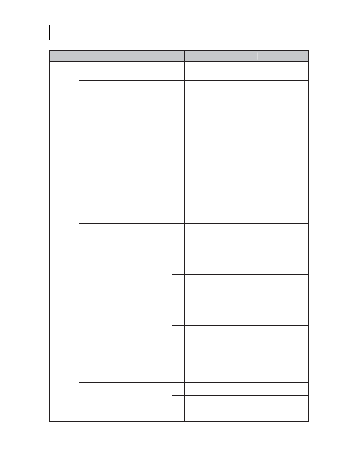
Tightening torque
Location
Q’ty Part name Tightening torque
Recoil
starter
Recoil Starter Body Ass'y
[64](64){66}<66>
4
Hex. Socket Hd. Bolt
(W/Flange) M4 x 18
[3](3){10}<10>
1.5 to 2.5 N•m
{15 to 25 kgf•cm}
Starter Pulley Ass’y [60](60){62}<62>
1M8
9.0 to 12 N•m
{92 to 122 kgf•cm}
Electrical
system
Ignition Coil Ass’y
[119](119){119}<119>
2
Hex. Socket Hd. Bolt
(W/Washers) M4 x 18
[118](118){118}<118>
2.5 to 4.5 N•m
{26 to 46 kgf•cm}
Magneto Rotor Ass’y [124](124)
Magneto Rotor Comp. {124}<124>
1
Flywheel Nut
[116](116){116}<116>
15 to 20 N•m
{153 to 204 kgf•cm}
Spark Plug Ass'y BMR7A
[13](13){13}<13>
1M14
10 to 15 N•m
{102 to 153 kgf•cm}
Carburetor
Air Cleaner Housing [42](42){43}<43>
2
Machine Screw (W/Washers)
M5 x 60 (Black)
[40](40){41}<41>
4.0 to 6.0 N•m
{41 to 61 kgf•cm}
Carburetor Insulator [21](21){21}<21>
2
Seal Lock Hex. Socket Bolt
(W/Washer) M5
[12](12){22}<22>
3.0 to 4.0 N•m
{31 to 41 kgf•cm}
Engine
Crank Case Ass’y [53](53)
4
Hex. Socket Hd. Bolt
(W/Sp. Washer) M5 x 18
[8](8){53}<53>
4.0 to 8.0 N•m
{41 to 82 kgf•cm}
Crank Case (A) Ass’y {60}<60>
Crank Case (B) Ass’y {54}<54>
Scavenging Cover (A) [15](15){15}<15>
Scavenging Cover (B) [18](18){18}<18>
4
Hex. Socket Hd. Bolt M4 x 12
[16](16){16}<16>
2.5 to 4.5 N•m
{25 to 46 kgf•cm}
Muffler (B) [6](6){5}<5>
2
Hex. Socket Hd. Bolt M6 x 65
[4](4){3}<3>
10 to 12 N•m
{102 to 122 kgf•cm}
Cylinder [19](19){19}<19>
4
Hex. Socket Hd. Bolt (W/Sp.
Washer) M5 x 18 [8](8)
6.0 to 9.0 N•m
{61 to 92 kgf•cm}
4
Hex. Socket Bolt M5 x 20
{7}<7>
6.0 to 9.0 N•m
{61 to 92 kgf•cm}
Clutch [114](114){114}<114>
2
Step Bolt [111](111){111}<111>
7.0 to 12 N•m
{71 to 122 kgf•cm}
Fan Case (A) [107](107){107}<107>
2
Seal Lock Hex. Socket Bolt
(W/Washers) M5 [12](12)
3.5 to 4.5 N•m
{36 to 46 kgf•cm}
1
Seal Lock Hex. Socket Hd. Bolt
M5 x 30 [1](1)
3.5 to 4.5 N•m
{36 to 46 kgf•cm}
3
Seal Lock Hex. Socket Hd. Bolt
M5 x 30 {12}<12>
3.5 to 4.5 N•m
{36 to 46 kgf•cm}
Muffler Cover {2}<2>
2
Screw (W/Washers) M5 x 16
(Black) {1}<1>
2.0 to 3.0 N•m
{20 to 31 kgf•cm}
Tank (B) [133](133){132}<132>
3
Bolt (W/Flange) L27.8
[137](137)
2.5 to 3.5 N•m
{26 to 36 kgf•cm}
1
Bolt (W/Flange) L27.8
{137}<137>
2.5 to 3.5 N•m
{26 to 36 kgf•cm}
2
Flange Bolt {136}<136>
2.5 to 3.5 N•m
{26 to 36 kgf•cm}
Shaft
Main Pipe [185]{185}
Main Pipe (A) (163)<163>
1
Hex. Socket Hd. Bolt (W/Sp.
Washer) M5 x 12
[100](100){100}<100>
3.5 to 4.5 N•m
{36 to 46 kgf•cm}
2
Hex. Hole Bolt 5 x 22/S
[101](101){101}<101>
3.5 to 4.5 N•m
{36 to 46 kgf•cm}
Gear Case Ass’y (4BB)
[160](170){160}<170>
1
Hex. Socket Hd. Bolt M5 x 30
[161](171){161}<171>
4.0 to 5.0 N•m
{41 to 51 kgf•cm}
1
Screw 5 x 12/W.S
[162](172){162}<172>
3.0 to 4.0 N•m
{31 to 41 kgf•cm}
1
Bolt (W/Plus) M6 x 8
[165](175){165}<175>
3.9 to 5.9 N•m
{40 to 60 kgf•cm}
Page 24
-23-
Confirmation after reassembl
y
Location
Q’ty Part name Tightening torque
Shaft
Joint Case (169)<169>
1
Hex. Socket Hd. Bolt M5 x 12
(154)<154>
4.0 to 7.0 N•m
{41 to 71 kgf•cm}
1
Hex. Socket Hd. Bolt
(W/Button) M6 (156)<156>
6.0 to 9.0 N•m
{61 to 92 kgf•cm}
Hanger [187](166){187}<166>
1 M5 hex. screw
3.0 to 4.0 N•m
{31 to 41 kgf•cm}
Throttle Lever (B) [151]{151}
1 M5 screw
2.0 to 3.0 N•m
{20 to 31 kgf•cm}
2 P tite screw
1.3 to 1.7 N•m
{13 to 17 kgf•cm}
Throttle Lever (A) Ass’y
[99](99){99}<99>
1 M5 screw
1.5 to 2.0 N•m
{15 to 20 kgf•cm}
4 P tite screw
1.3 to 2.0 N•m
{13 to 20 kgf•cm}
Handle Holder (C) [158]{158}
2
Hex. Hole Button Screw
6 x 25S [159]{159}
4.0 to 7.0 N•m
{41 to 71 kgf•cm}
Other Throttle wire 1 M6 nut
1.0 to 3.0 N•m
{10 to 31 kgf•cm}
1. Check the following before starting the engine.
(1) Confirm that all fastening screws, bolts and nuts are properly tightened.
(2) Confirm that there is no gas leaking from any part of the engine section.
(3) Confirm that the crank shaft rotates and there is compression when pulling the starter handle.
(4) Perform priming ten times and then confirm that the priming pump is full of fuel.
2. Check the following after starting the engine.
(1) Confirm that the engine starts up by following the procedure b elow.
(a) Set the stop switch to the startup position.
(b) Perform priming ten times.
(c) Set the choke lever to the CLOSED position (
).
(d) Pull the starter handle and check for initial ignition. (As a guide, pull the handle 3 to 5 times at
ambient temperature of 20°C. Pull the handle more at lower temperatures.)
(e) Set the choke lever to the RUN position (
).
(f) Pull the starter handle to start the engine. (As a guide, pull the handle 2 or 3 times at ambient
temperature of 20°C. Pull the handle more at lower temperatures.)
(2) Confirm that each moving part functions properly, and that rotating parts make no abnormal noise.
(3) Check the speed as follows and adjust the carburetor according to “2. Checking and adjusting the
carburetor ass’y” on page 10.
(a) Speed at full throttle for up to 30 seconds after idling for 30 seconds
• When attaching the cutter blade: 8,500 to 12,500 min
-1
• When attaching the nylon cord: 8,200 min-1 or higher (projecting part of nylon cord: 170 mm)
(b) Idling speed (Increase the speed to 6,000 to 8,000 min
-1
prior to measurement.)
The idling speed should be stable for at least 10 seconds at 2,500 to 3,500 min
-1
. Make sure the
cutting attachment does not rotate.
(c) Clutch-in speed (at which the cutting attachment starts to rotate): 3,800 to 4,800 min
-1
(4) Make sure that the engine accelerates smoothly.
(5) Release the throttle lever and make sure that the engine idles.
(6) Let the engine idle, and then rapidly accelerate and decelerate the engine. Make sure that the engine
does not stop.
(7) Confirm that the stop switch functions properly.
Page 25
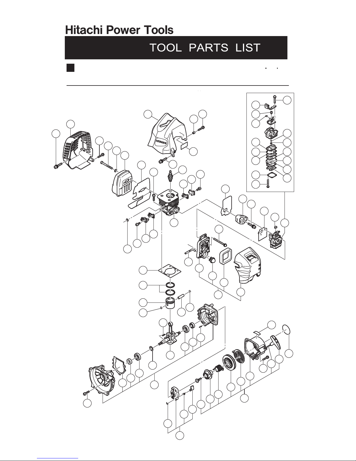
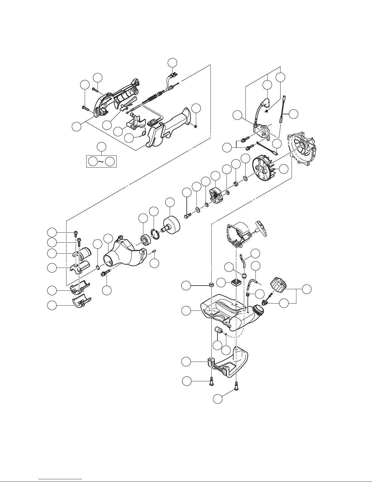
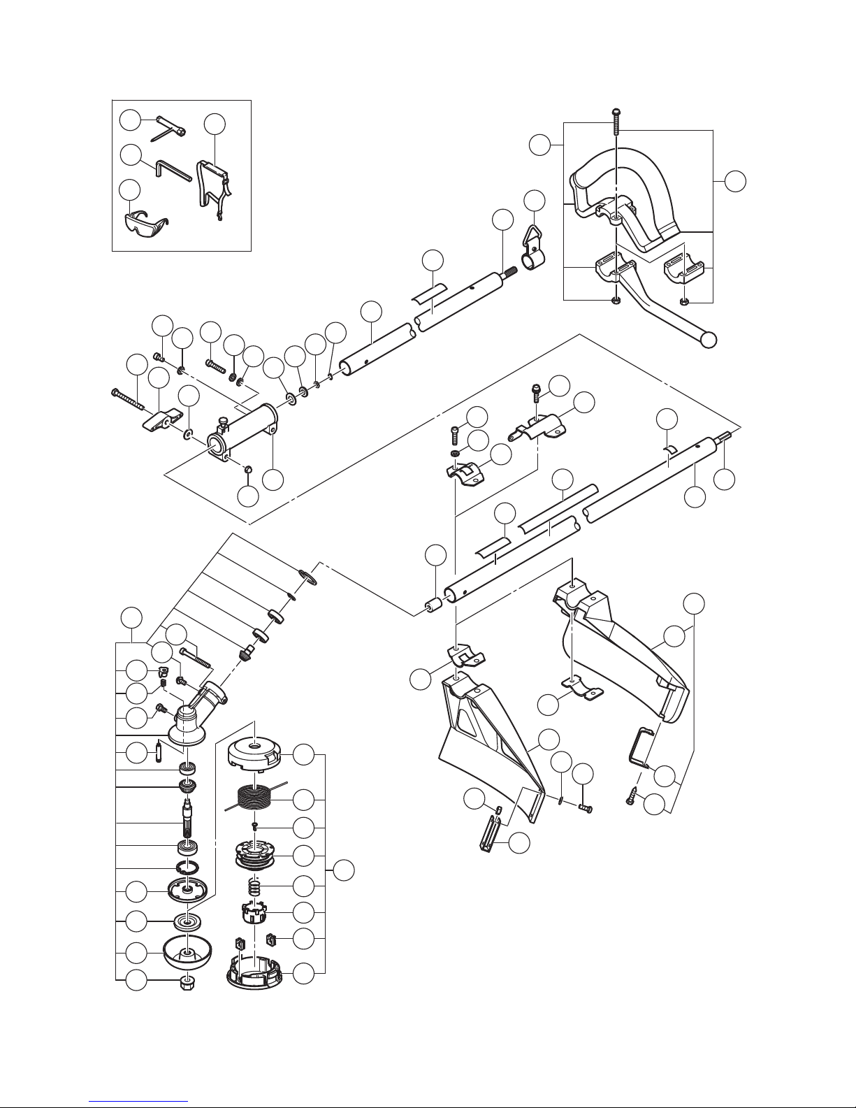
ENGINE
Model CG 24EBD
ENGINE BRUSH CUTTER
LIST NO. F053
(E1)
2014
4 25
A
B
2
3
4
5
6
7
8
17
16
18
14
9
3
13
14
15
16
19
21
12
22
23
24
25
26
27
28
29
30
31
32
33
34
35
36
37
38
39
40
41
42
43
44
45
46
47
48
49
50
51
50
8
53
54
55
56
57
58
56
55
59
60
61
62
63
65
66
67
68
69
70
71
72
73
64
20
12
3
52
74
1
11
10
Page 26
A
B
100
101
102
103
104
105
106
12
107
111
112
113
114
115
116
117
119
120
121
118
122
123
124
130
125
127
128
129
133
134
135
136
91
92
98
96
97
93
94
99
110
95
98
131
137
91
126
108
109
132
137
59
4
-
14
CG 24EBD
- 2 -
Page 27
167
168
171
178
179
180
181
173
190
182
183
184
185
186
187
188
189
501
502
503
504
172
191
192
193
194
195
193
205
202
203
206
207
208
204
209
210
211
198
199
200
201
197
196
166
151
152
153
154
155
156
157
158
159
160
161
162
163
164
165
169
170
174
175
177
176
CG 24EBD
4 - 14
- 3 -
Page 28

PART
S
CG 24EBD
DESCRIPTION REMARKS
1 6698950 SEAL LOCK HEX. SOCKET HD. BOLT M5 X 30 1
2 6698478 MUFFLER COVER 1
3 6696326
HEX. SOCKET HD. BOLT (W/FLANGE) M4 X 18 4
4 6696819 HEX. SOCKET HD. BOLT M6 X 55 2
5 949432 BOLT WASHER M6 (10 PCS.) 2
6 6698477 MUFFLER 1
7 6600320 HEAT PROTECTION PANEL 1
8 6698386
HEX. SOCKET HD. BOLT (W/SP.WASHER) M5 X 18 8
9 6699454 CYLINDER COVER 1
10 6600008 COLLAR (B) 2
* 11 RCM+EAC MARK 1 FOR AUS,NZL
12 6698844
SEAL LOCK HEX. SOCKET BOLT (W/WASHERS) M5 4
* 13 6699322 SPARK PLUG ASS'Y CJ6 1
* 13 6699316 SPARK PLUG ASS'Y BMR7A 1 FOR AUS,NZL
14 6698468 COVER PACKING 2
15 6698469 SCAVENGING COVER (A) 1
16 6698385 HEX. SOCKET HD. BOLT M4 X 12 4
17 6698700 GLASS WASHER 2
18 6698470 SCAVENGING COVER (B) 1
19 6698465 CYLINDER 1
20 6699437 INTAKE PACKING 1
21 6698387 CARBURETOR INSULATOR 1
22 6698405 CARBURETOR PACKING 1
23 6691337 SWIVEL CAP 1
24 6600321 CARBURETOR ASS'Y WYC-36 1 INCLUD.25-39
25 6699287 CABLE ADJUST STAY 1
26 6696830 SWIVEL 1
27 6684696 STOP RING 1
28 6684692 PUMP GASKET 1
29 6684693 PUMP DIAPHRAGM 1
30 6691242 PUMP PLATE 1
31 6685222 DIAPHRAGM COVER-METERING 1
32 6691312 SET SCREW 4
33 6696829 SET SCREW M3 X 12 2
34 6684695 O-RING 1
35 MAIN JET 1
36 6691234 CIRCUIT PLATE 1
37 6696828 PUMP BODY COMP. 1
38 6685220 DIAPHRAGM PACKING-METERING 1
39 6684690 METERING DIAPHRAGM 1
40 307224
MACHINE SCREW (W/WASHERS) M5 X 60 (BLACK) 2
41 6699014 FUEL PIPE L70 1
42 6696832 AIR CLEANER HOUSING 1
43 6685139 PRIMING PUMP COMP. 1
44 6690347 CLEANER ELEMENT 1
45 6699185 CLEANER COVER 1
46 6699132 AIR CLEANER (A) ASS'Y 1 INCLUD.42-45
47 6684587 CYLINDER GASKET 1
48 6698404 PISTON RING 2
49 6699456 PISTON 1
- 4 - 4 - 14 *ALTERNATIVE PARTS
ITEM
NO.
NO.
USED
CODE NO.
Page 29

PART
S
CG 24EBD
DESCRIPTION REMARKS
50 6684590 CIR CLIP 2
51 6684899 WOODRUFF KEY 3 X 13 X 4.5 1
52 6684591 PISTON PIN 1
53 6684606 CRANK CASE ASS'Y 1 INCLUD.54-56,59
54 6684609 CRANK CASE GASKET 1
55 6684607 OIL SEAL TB 12227 2
56 6684608 BALL BEARING 6001 C3 2
* 57 6696946 SHIM T0.2 1
* 57 6696945 SHIM T0.3 1
58 6696533 CRANK SHAFT COMP. 1
59 6696947 KNOCK PIN 4 X 12 4
60 6684681 STARTER PULLEY ASS'Y 1 INCLUD.61-63
61 6684683 STOP RING E-5 2
62 6684684 STARTER PAWL SPRING 2
63 6684685 STARTER PAWL 2
64 6699995 RECOIL STARTER BODY ASS'Y 1 INCLUD.65-72
65 6684679 SET SCREW 1
66 6699996 CAM PLATE 1
67 6684677 DAMPER SPRING 1
68 6699997 STARTER ROPE REEL 1
69 6684675 RECOIL SPRING 1
70 6684673 RECOIL STARTER BODY COMP. 1
71 6684674 STARTER ROPE 3.5 X 860 1
72 6684680 STARTER HANDLE 1
73 NAME PLATE 1
* 74 6698922 TANK MARK LABEL (25:1) 1
* 74 6698921 TANK MARK LABEL (50:1) 1 FOR AUS,NZL
91 6699195 MACHINE SCREW M5 X 20 (BLACK) 2
92 6699194 P TIGTH SCREW D4 X 20 (BLACK) 4
93 6699197 SWITCH WIRE SET 1
94 6699196 NUT M5 2
95 6699192 STOP LEVER 1
96 6699191 LONG LEVER 1
97 6699193 RETURN SPRING 1
98 6699190 STAY SET 1
99 6699133 THROTTLE LEVER (A) ASS'Y 1 INCLUD.91-98
100 6699176
HEX. SOCKET HD. BOLT (W/SP.WASHER) M5 X 12 1
101 6695492 HEX. HOLE BOLT 5 X 22/S 2
102 6696963 ANTI VIBE RUBBER (A) 1
103 6698643 PIPE HOLDER (A) 1
104 6698644 PIPE HOLDER (B) 1
105 6696964 ANTI VIBE RUBBER (B) 1
106 939542 RETAINING RING FOR D12 SHAFT (10 PCS.) 1
107 6699457 FAN CASE (A) 1
108 6699435 BALL BEARING 6301ZZC3 1
109 322813 RETAINING RING 37MM 1
110 6699434 CLUTCH SHAFT 1
111 6696469 STEP BOLT 2
112 6684648 BENT WASHER 8 2
113 6696546 CLUTCH PLATE (A) 2
4 - 14 - 5 - *ALTERNATIVE PARTS
NO.
USED
CODE NO.
ITEM
NO.
Page 30

PART
S
CG 24EBD
DESCRIPTION REMARKS
114 6699130 CLUTCH 1
115 6699131 CLUTCH WASHER (B) 2
116 6685337 FLYWHEEL NUT 1
117 323212 BOLT WASHER M8 (BLACK) 1
118 6698388
HEX. SOCKET HD. BOLT (W/WASHERS) M4 X 18 2
119 6699458 IGNITION COIL ASS'Y 1 INCLUD.120,121
120 6699932 PLUG CAP 1
121 6699933 METAL FITTING OF PLUG CAP 1
122 6696544 CORD 1
123 6696545 EARTH CORD 1
124 6699289 MAGNETO ROTOR ASS'Y 1
125 6698716 FUEL PIPE 1
126 6698401 FUEL PIPE (PINK) 1
127 6697846 RETURN GROMMET 1
128 6698402 FUEL TANK CAP ASS'Y 1 INCLUD.129
129 6698732 TANK CAP CHAIN 1
130 6698931 FUEL GROMMET 1
131 6699558 SPACER 1
132 6699459 SPACER (B) 2
133 6600317 TANK (B) 1
134 6684620 PUMP FILTER BODY COMP. 1
135 6696949 CLIP 1
136 6694787 STAND 1
137 6698991 BOLT (W/FLANGE) L27.8 3
151 6684824 HEX. BOLT 6 X 50 1
152 6684823 HANDLE KNOB 1
153 6684822 SPECIAL WASHER B 1
154 6684829 HEX. SOCKET HD. BOLT M5 X 12 1
155 6698884 SPRING WASHER M5 1
156 6684825 HEX. SOCKET HD. BOLT (W/BUTTON) M6 1
157 949455 SPRING WASHER M6 (10 PCS.) 1
158 949425 WASHER M6 (10 PCS.) 1
159 6689139 SPACER 1.6 1
160 6684819 SPACER 1
161 6684820 PULLEY WASHER 1
162 939540 RETAINING RING FOR D10 SHAFT (10 PCS.) 1
163 6699460 MAIN PIPE (A) 1
* 164 6684852 LEVEL MARK 1 FOR AUS,NZL
165 6699462 DRIVE SHAFT (A) 1
166 6696493 HANGER 1
* 167 6699448 LOOP HANDLE (W/BARRIER) 1 FOR AUS,NZL
* 168 6699449 LOOP HANDLE 1 FOR ISR
169 6684828 CAP NUT 6 1
170 6684817 JOINT CASE 1
* 171 6699439 GEAR CASE ASS'Y (4BB) 1 INCLUD.172-181 FOR (SL)
* 172 949664 HEX. SOCKET HD. BOLT M5 X 30 (10 PCS.) 1 FOR (SL)
* 173 6695414 SCREW 5 X 12/W.S 1 FOR (SL)
* 174 6600005 CAP 1 FOR (SL)
* 175 6600006 SPRING 1 FOR (SL)
* 176 6684737 BOLT (W/PLUS) M6 X 8 1 FOR (SL)
- 6 - 4 - 14 *ALTERNATIVE PARTS
NO.
USED
CODE NO.
ITEM
NO.
Page 31

CG 24EBD
DESCRIPTION REMARKS
* 177 6600007 LOCK PIN 1 FOR (SL)
* 178 6699441 CUTTER HOLDER (A) 1 FOR (SL)
* 179 6698659 CUTTER HOLDER (B) 1 FOR (SL)
* 180 6699188 NUT COVER 1 FOR (SL)
* 181 335759 U-NUT (LEFT HAND) M10 1 FOR (SL)
* 182 6698794 COVER 1 FOR (SL)
* 183 NYLON CORD 1 FOR (SL)
* 184 6698795 SET SCREW 1 FOR (SL)
* 185 6698796 REEL 1 FOR (SL)
* 186 6698797 RETURN SPRING 1 FOR (SL)
* 187 6698798 BUTTON 1 FOR (SL)
* 188 6698799 CORD GUIDE 2 FOR (SL)
* 189 6698800 CASE 1 FOR (SL)
* 190 6696454 NYLON HEAD ASS'Y 1 INCLUD.182-189 FOR (SL)
* 191 6685064
HEX. SOCKET HD. BOLT (W/BUTTON) M6 X 20 2 FOR ISR (SL)
* 192 949455 SPRING WASHER M6 (10 PCS.) 2 FOR ISR (SL)
* 193 6696978 COVER BRACKET 2 FOR ISR (SL)
* 194 6684714 HEX. HOLE BUTTON SCREW 6 X 25S 2 FOR AUS (SL),NZL (SL)
* 195 6699444 COVER BRACKET 1 FOR AUS (SL),NZL (SL)
* 196 6684833 BUSHING 1 FOR (SL)
* 197 6685061 LEVEL MARK 1 FOR ISR (SL)
* 198 6697625 CAUTION MARK HITACHI 1 FOR (SL)
* 199 6684851 LEVEL MARK 1 FOR (SL)
* 200 6699461 MAIN PIPE (A) 1 FOR (SL)
* 201 6684832 DRIVE SHAFT B 783L 1 FOR (SL)
* 202 949554 NUT M4 (10 PCS.) 2 FOR ISR (SL)
* 203 6696584 KNIFE 1 FOR ISR (SL)
* 204 6698813 COVER HOLDER 1 FOR AUS (SL),NZL (SL)
* 205 6696981 GUARD 1 FOR ISR (SL)
* 206 323210 BOLT WASHER M4 (BLACK) 2 FOR ISR (SL)
* 207 6685068 MACHINE SCREW (W/SP. WASHER) M4 X 12 2 FOR ISR (SL)
* 208 6697880 COVER ASS'Y 1
INCLUD.209-211 FOR AUS (SL),NZL (SL)
* 209 6690272 GUARD 24 DIA. 1 FOR AUS (SL),NZL (SL)
* 210 6693388 KNIFE 1 FOR AUS (SL),NZL (SL)
* 211 6684753 TAPPING SCREW 5 X 20 1 FOR AUS (SL),NZL (SL)
4 - 14 - 7 -
PART
S
*ALTERNATIVE PARTS
NO.
USED
CODE NO.
ITEM
NO.
Page 32

CG 24EBD
DESCRIPTION REMARKS
501 6684764 BOX WRENCH (HEX. SOCKET 17/19) 1
502 944458 HEX. BAR WRENCH 4MM 1
503 875769 SAFETY GLASSES 1
* 504 6696448 SHOULDER BELT SINGLE 1
* 504 6695795 SHOULDER STRAP S 1 FOR AUS,NZL
- 8 - Printed in Japan 4 - 14
(140425N)
*ALTERNATIVE PARTS
STANDARD ACCESSORIES
NO.
USED
CODE NO.
ITEM
NO.
CODE NO.
Page 33

ENGINE
Model CG 24EBDP
ENGINE BRUSH CUTTER
LIST NO. F054
(E1)
2014
4 25
A
B
4
5
75
76
2
3
6
7
8
17
16
18
14
9
3
13
14
15
16
19
21
12
22
23
24
25
26
27
28
29
30
31
32
33
34
35
36
37
38
39
40
41
42
43
44
45
46
47
48
49
50
51
50
8
53
54
55
56
57
58
56
55
59
60
61
62
63
65
66
67
68
69
70
71
72
73
64
11
20
12
3
52
74
1
10
77
78
Page 34

A
B
100
101
102
103
104
105
106
12
107
111
112
113
114
115
116
117
119
120
121
118
122
123
124
130
125
127
128
129
133
134
135
136
91
92
98
96
97
93
94
99
110
95
98
131
137
91
126
108
109
132
137
59
4 - 14
CG 24EBDP
- 2 -
Page 35

167
170
175
177
178
179
180
172
189
181
182
183
184
185
186
187
188
501
502
503
504
171
194
195
196
166
151
152
153
154
155
156
157
158
159
160
161
162
163
164
165
168
169
197
193
192
190
191
198
199
200
201
173
174
176
202
CG 24EBDP
4 - 14
- 3 -
Page 36

PART
S
CG 24EBDP
DESCRIPTION REMARKS
1 6698950 SEAL LOCK HEX. SOCKET HD. BOLT M5 X 30 1
2 6600319 MUFFLER COVER 1
3 6696326
HEX. SOCKET HD. BOLT (W/FLANGE) M4 X 18 4
4 6698384 HEX. SOCKET HD. BOLT M6 X 65 2
5 949432 BOLT WASHER M6 (10 PCS.) 2
6 6600004 MUFFLER (B) 1
7 6600320 HEAT PROTECTION PANEL 1
8 6698386
HEX. SOCKET HD. BOLT (W/SP.WASHER) M5 X 18 8
9 6699454 CYLINDER COVER 1
10 6600008 COLLAR (B) 2
11 CAUTION LABEL 1
12 6698844
SEAL LOCK HEX. SOCKET BOLT (W/WASHERS) M5 4
13 6699316 SPARK PLUG ASS'Y BMR7A 1
14 6698468 COVER PACKING 2
15 6698469 SCAVENGING COVER (A) 1
16 6698385 HEX. SOCKET HD. BOLT M4 X 12 4
17 6698700 GLASS WASHER 2
18 6698470 SCAVENGING COVER (B) 1
19 6698465 CYLINDER 1
20 6699437 INTAKE PACKING 1
21 6698387 CARBURETOR INSULATOR 1
22 6698405 CARBURETOR PACKING 1
23 6691337 SWIVEL CAP 1
24 6600321 CARBURETOR ASS'Y WYC-36 1 INCLUD.25-39
25 6699287 CABLE ADJUST STAY 1
26 6696830 SWIVEL 1
27 6684696 STOP RING 1
28 6684692 PUMP GASKET 1
29 6684693 PUMP DIAPHRAGM 1
30 6691242 PUMP PLATE 1
31 6685222 DIAPHRAGM COVER-METERING 1
32 6691312 SET SCREW 4
33 6696829 SET SCREW M3 X 12 2
34 6684695 O-RING 1
35 MAIN JET 1
36 6691234 CIRCUIT PLATE 1
37 6696828 PUMP BODY COMP. 1
38 6685220 DIAPHRAGM PACKING-METERING 1
39 6684690 METERING DIAPHRAGM 1
40 307224
MACHINE SCREW (W/WASHERS) M5 X 60 (BLACK) 2
41 6699014 FUEL PIPE L70 1
42 6696832 AIR CLEANER HOUSING 1
43 6685139 PRIMING PUMP COMP. 1
44 6690347 CLEANER ELEMENT 1
45 6699185 CLEANER COVER 1
46 6699132 AIR CLEANER (A) ASS'Y 1 INCLUD.42-45
47 6684587 CYLINDER GASKET 1
48 6698404 PISTON RING 2
49 6699456 PISTON 1
50 6684590 CIR CLIP 2
- 4 - 4 - 14 *ALTERNATIVE PARTS
ITEM
NO.
NO.
USED
CODE NO.
Page 37

PART
S
CG 24EBDP
DESCRIPTION REMARKS
51 6684899 WOODRUFF KEY 3 X 13 X 4.5 1
52 6684591 PISTON PIN 1
53 6684606 CRANK CASE ASS'Y 1 INCLUD.54-56,59
54 6684609 CRANK CASE GASKET 1
55 6684607 OIL SEAL TB 12227 2
56 6684608 BALL BEARING 6001 C3 2
* 57 6696946 SHIM T0.2 1
* 57 6696945 SHIM T0.3 1
58 6696533 CRANK SHAFT COMP. 1
59 6696947 KNOCK PIN 4 X 12 4
60 6684681 STARTER PULLEY ASS'Y 1 INCLUD.61-63
61 6684683 STOP RING E-5 2
62 6684684 STARTER PAWL SPRING 2
63 6684685 STARTER PAWL 2
64 6699995 RECOIL STARTER BODY ASS'Y 1 INCLUD.65-72
65 6684679 SET SCREW 1
66 6699996 CAM PLATE 1
67 6684677 DAMPER SPRING 1
68 6699997 STARTER ROPE REEL 1
69 6684675 RECOIL SPRING 1
70 6684673 RECOIL STARTER BODY COMP. 1
71 6684674 STARTER ROPE 3.5 X 860 1
72 6684680 STARTER HANDLE 1
73 NAME PLATE 1
74 6698921 TANK MARK LABEL (50:1) 1
75 6600323 MUFFLER HEAT COVER 1
76 6600325 TAPPING SCREW D4 X 10 2
77 6600327 MARK PLATE (T) 1
78 6699000 PRIMER LABEL 1
91 6699195 MACHINE SCREW M5 X 20 (BLACK) 2
92 6699194 P TIGTH SCREW D4 X 20 (BLACK) 4
93 6699197 SWITCH WIRE SET 1
94 6699196 NUT M5 2
95 6699192 STOP LEVER 1
96 6699191 LONG LEVER 1
97 6699193 RETURN SPRING 1
98 6699190 STAY SET 1
99 6699133 THROTTLE LEVER (A) ASS'Y 1 INCLUD.91-98
100 6699176
HEX. SOCKET HD. BOLT (W/SP.WASHER) M5 X 12 1
101 6695492 HEX. HOLE BOLT 5 X 22/S 2
102 6696963 ANTI VIBE RUBBER (A) 1
103 6698643 PIPE HOLDER (A) 1
104 6698644 PIPE HOLDER (B) 1
105 6696964 ANTI VIBE RUBBER (B) 1
106 939542 RETAINING RING FOR D12 SHAFT (10 PCS.) 1
107 6699457 FAN CASE (A) 1
108 6699435 BALL BEARING 6301ZZC3 1
109 322813 RETAINING RING 37MM 1
110 6699434 CLUTCH SHAFT 1
111 6696469 STEP BOLT 2
4 - 14 - 5 - *ALTERNATIVE PARTS
NO.
USED
CODE NO.
ITEM
NO.
Page 38

PART
S
CG 24EBDP
DESCRIPTION REMARKS
112 6684648 BENT WASHER 8 2
113 6696546 CLUTCH PLATE (A) 2
114 6699130 CLUTCH 1
115 6699131 CLUTCH WASHER (B) 2
116 6685337 FLYWHEEL NUT 1
117 323212 BOLT WASHER M8 (BLACK) 1
118 6698388
HEX. SOCKET HD. BOLT (W/WASHERS) M4 X 18 2
119 6699458 IGNITION COIL ASS'Y 1 INCLUD.120,121
120 6699932 PLUG CAP 1
121 6699933 METAL FITTING OF PLUG CAP 1
122 6696544 CORD 1
123 6696545 EARTH CORD 1
124 6699289 MAGNETO ROTOR ASS'Y 1
125 6698716 FUEL PIPE 1
126 6698401 FUEL PIPE (PINK) 1
127 6697846 RETURN GROMMET 1
128 6698402 FUEL TANK CAP ASS'Y 1 INCLUD.129
129 6698732 TANK CAP CHAIN 1
130 6698931 FUEL GROMMET 1
131 6699558 SPACER 1
132 6699459 SPACER (B) 2
133 6600317 TANK (B) 1
134 6684620 PUMP FILTER BODY COMP. 1
135 6696949 CLIP 1
136 6694787 STAND 1
137 6698991 BOLT (W/FLANGE) L27.8 3
151 6684824 HEX. BOLT 6 X 50 1
152 6684823 HANDLE KNOB 1
153 6684822 SPECIAL WASHER B 1
154 6684829 HEX. SOCKET HD. BOLT M5 X 12 1
155 6698884 SPRING WASHER M5 1
156 6684825 HEX. SOCKET HD. BOLT (W/BUTTON) M6 1
157 949455 SPRING WASHER M6 (10 PCS.) 1
158 949425 WASHER M6 (10 PCS.) 1
159 6689139 SPACER 1.6 1
160 6684819 SPACER 1
161 6684820 PULLEY WASHER 1
162 939540 RETAINING RING FOR D10 SHAFT (10 PCS.) 1
163 6699460 MAIN PIPE (A) 1
164 6684852 LEVEL MARK 1
165 6699462 DRIVE SHAFT (A) 1
166 6696493 HANGER 1
167 6699448 LOOP HANDLE (W/BARRIER) 1
168 6684828 CAP NUT 6 1
169 6684817 JOINT CASE 1
* 170 6699439 GEAR CASE ASS'Y (4BB) 1 INCLUD.171-180 FOR (SL)
* 171 949664 HEX. SOCKET HD. BOLT M5 X 30 (10 PCS.) 1 FOR (SL)
* 172 6695414 SCREW 5 X 12/W.S 1 FOR (SL)
* 173 6600005 CAP 1 FOR (SL)
* 174 6600006 SPRING 1 FOR (SL)
- 6 - 4 - 14 *ALTERNATIVE PARTS
NO.
USED
CODE NO.
ITEM
NO.
Page 39

CG 24EBDP
DESCRIPTION REMARKS
* 175 6684737 BOLT (W/PLUS) M6 X 8 1 FOR (SL)
* 176 6600007 LOCK PIN 1 FOR (SL)
* 177 6699441 CUTTER HOLDER (A) 1 FOR (SL)
* 178 6698659 CUTTER HOLDER (B) 1 FOR (SL)
* 179 6699188 NUT COVER 1 FOR (SL)
* 180 335759 U-NUT (LEFT HAND) M10 1 FOR (SL)
* 181 6698794 COVER 1 FOR (SL)
* 182 NYLON CORD 1 FOR (SL)
* 183 6698795 SET SCREW 1 FOR (SL)
* 184 6698796 REEL 1 FOR (SL)
* 185 6698797 RETURN SPRING 1 FOR (SL)
* 186 6698798 BUTTON 1 FOR (SL)
* 187 6698799 CORD GUIDE 2 FOR (SL)
* 188 6698800 CASE 1 FOR (SL)
* 189 6696454 NYLON HEAD ASS'Y 1 INCLUD.181-188 FOR (SL)
* 190 6684714 HEX. HOLE BUTTON SCREW 6 X 25S 2 FOR (SL)
* 191 6699442 COVER BRACKET 1 FOR (SL)
* 192 6684833 BUSHING 1 FOR (SL)
* 193 6697625 CAUTION MARK HITACHI 1 FOR (SL)
* 194 6684851 LEVEL MARK 1 FOR (SL)
* 195 6699461 MAIN PIPE (A) 1 FOR (SL)
* 196 6684832 DRIVE SHAFT B 783L 1 FOR (SL)
* 197 6696980 COVER 1 FOR (SL)
* 198 6696951 GUARD HOLDER 1 FOR (SL)
* 199 6696950 COVER GUARD 1 FOR (SL)
* 200 6684751 TAPPING SCREW 4 X 14 1 FOR (SL)
* 201 6684750 KNIFE 1 FOR (SL)
202 6600328 CAUTION LABEL (HEDGE) 1
4 - 14 - 7 -
PART
S
*ALTERNATIVE PARTS
NO.
USED
CODE NO.
ITEM
NO.
Page 40

CG 24EBDP
DESCRIPTION REMARKS
501 6684764 BOX WRENCH (HEX. SOCKET 17/19) 1
502 944458 HEX. BAR WRENCH 4MM 1
503 875769 SAFETY GLASSES 1
504 6696448 SHOULDER BELT SINGLE 1
- 8 - Printed in Japan 4 - 14
(140425N)
*ALTERNATIVE PARTS
STANDARD ACCESSORIES
NO.
USED
CODE NO.
ITEM
NO.
CODE NO.
Page 41

ENGINE
Model CG 24EBS
ENGINE BRUSH CUTTER
LIST NO. F055
(E1)
2014
4 25
A
B
2
3
4
5
6
7
8
17
16
18
14
9
3
13
14
15
16
19
21
12
22
23
24
25
26
27
28
29
30
31
32
33
34
35
36
37
38
39
40
41
42
43
44
45
46
47
48
49
50
51
50
8
53
54
55
56
57
58
56
55
59
60
61
62
63
65
66
67
68
69
70
71
72
73
64
20
12
3
52
74
1
11
10
Page 42

A
B
12
100
101
102
103
104
105
106
59
107
111
112
113
114
115
116
117
119
120
121
118
122
123
124
130
125
127
128
129
133
134
135
136
91
92
98
96
97
93
94
99
110
95
98
131
137
91
126
108
109
132
137
4 - 14
CG 24EBS
- 2 -
Page 43

152
153
157
151
158
159
160
154
155
156
161
166
168
169
170
171
163
181
180
172
173
174
175
176
177
178
179
182
196
195
197
198
199
183
184
187
188
189
190
191
192
193
194
185
501
502
503
504
505
507
506
181
186
185
203
200
201
204
205
207
202
208
209
210
506
206
162
164
165
167
CG 24EBS
4 - 14
- 3 -
Page 44

PART
S
CG 24EBS
DESCRIPTION REMARKS
1 6698950 SEAL LOCK HEX. SOCKET HD. BOLT M5 X 30 1
2 6698478 MUFFLER COVER 1
3 6696326
HEX. SOCKET HD. BOLT (W/FLANGE) M4 X 18 4
4 6696819 HEX. SOCKET HD. BOLT M6 X 55 2
5 949432 BOLT WASHER M6 (10 PCS.) 2
6 6698477 MUFFLER 1
7 6600320 HEAT PROTECTION PANEL 1
8 6698386
HEX. SOCKET HD. BOLT (W/SP.WASHER) M5 X 18 8
9 6699454 CYLINDER COVER 1
10 6600008 COLLAR (B) 2
* 11 RCM+EAC MARK 1 FOR RUS,AUS,NZL
12 6698844
SEAL LOCK HEX. SOCKET BOLT (W/WASHERS) M5 4
* 13 6699322 SPARK PLUG ASS'Y CJ6 1
* 13 6699316 SPARK PLUG ASS'Y BMR7A 1 FOR RUS,AUS,NZL
14 6698468 COVER PACKING 2
15 6698469 SCAVENGING COVER (A) 1
16 6698385 HEX. SOCKET HD. BOLT M4 X 12 4
17 6698700 GLASS WASHER 2
18 6698470 SCAVENGING COVER (B) 1
19 6698465 CYLINDER 1
20 6699437 INTAKE PACKING 1
21 6698387 CARBURETOR INSULATOR 1
22 6698405 CARBURETOR PACKING 1
23 6691337 SWIVEL CAP 1
* 24 6600321 CARBURETOR ASS'Y WYC-36 1 INCLUD.25-39
* 24 6698728 CARBURETOR ASS'Y WYC-30 1 INCLUD.25-39 FOR BRA
25 6699287 CABLE ADJUST STAY 1
26 6696830 SWIVEL 1
27 6684696 STOP RING 1
28 6684692 PUMP GASKET 1
29 6684693 PUMP DIAPHRAGM 1
30 6691242 PUMP PLATE 1
31 6685222 DIAPHRAGM COVER-METERING 1
32 6691312 SET SCREW 4
33 6696829 SET SCREW M3 X 12 2
34 6684695 O-RING 1
35 MAIN JET 1
36 6691234 CIRCUIT PLATE 1
37 6696828 PUMP BODY COMP. 1
38 6685220 DIAPHRAGM PACKING-METERING 1
39 6684690 METERING DIAPHRAGM 1
40 307224
MACHINE SCREW (W/WASHERS) M5 X 60 (BLACK) 2
41 6699014 FUEL PIPE L70 1
42 6696832 AIR CLEANER HOUSING 1
43 6685139 PRIMING PUMP COMP. 1
44 6690347 CLEANER ELEMENT 1
45 6699185 CLEANER COVER 1
46 6699132 AIR CLEANER (A) ASS'Y 1 INCLUD.42-45
47 6684587 CYLINDER GASKET 1
48 6698404 PISTON RING 2
- 4 - 4 - 14 *ALTERNATIVE PARTS
ITEM
NO.
NO.
USED
CODE NO.
Page 45

PART
S
CG 24EBS
DESCRIPTION REMARKS
49 6699456 PISTON 1
50 6684590 CIR CLIP 2
51 6684899 WOODRUFF KEY 3 X 13 X 4.5 1
52 6684591 PISTON PIN 1
53 6684606 CRANK CASE ASS'Y 1 INCLUD.54-56,59
54 6684609 CRANK CASE GASKET 1
55 6684607 OIL SEAL TB 12227 2
56 6684608 BALL BEARING 6001 C3 2
* 57 6696946 SHIM T0.2 1
* 57 6696945 SHIM T0.3 1
58 6696533 CRANK SHAFT COMP. 1
59 6696947 KNOCK PIN 4 X 12 4
60 6684681 STARTER PULLEY ASS'Y 1 INCLUD.61-63
61 6684683 STOP RING E-5 2
62 6684684 STARTER PAWL SPRING 2
63 6684685 STARTER PAWL 2
64 6699995 RECOIL STARTER BODY ASS'Y 1 INCLUD.65-72
65 6684679 SET SCREW 1
66 6699996 CAM PLATE 1
67 6684677 DAMPER SPRING 1
68 6699997 STARTER ROPE REEL 1
69 6684675 RECOIL SPRING 1
70 6684673 RECOIL STARTER BODY COMP. 1
71 6684674 STARTER ROPE 3.5 X 860 1
72 6684680 STARTER HANDLE 1
73 NAME PLATE 1
* 74 6698921 TANK MARK LABEL (50:1) 1
* 74 6698922 TANK MARK LABEL (25:1) 1 FOR TPE,ISR
* 91 6699195 MACHINE SCREW M5 X 20 (BLACK) 2 FOR (SL)
* 92 6699194 P TIGTH SCREW D4 X 20 (BLACK) 4 FOR (SL)
* 93 6699197 SWITCH WIRE SET 1 FOR (SL)
* 94 6699196 NUT M5 2 FOR (SL)
* 95 6699192 STOP LEVER 1 FOR (SL)
* 96 6699191 LONG LEVER 1 FOR (SL)
* 97 6699193 RETURN SPRING 1 FOR (SL)
* 98 6699190 STAY SET 1 FOR (SL)
* 99 6699133 THROTTLE LEVER (A) ASS'Y 1 INCLUD.91-98 FOR (SL)
100 6699176
HEX. SOCKET HD. BOLT (W/SP.WASHER) M5 X 12 1
101 6695492 HEX. HOLE BOLT 5 X 22/S 2
102 6696963 ANTI VIBE RUBBER (A) 1
103 6698643 PIPE HOLDER (A) 1
104 6698644 PIPE HOLDER (B) 1
105 6696964 ANTI VIBE RUBBER (B) 1
106 939542 RETAINING RING FOR D12 SHAFT (10 PCS.) 1
107 6699457 FAN CASE (A) 1
108 6699435 BALL BEARING 6301ZZC3 1
109 322813 RETAINING RING 37MM 1
110 6699434 CLUTCH SHAFT 1
111 6696469 STEP BOLT 2
112 6684648 BENT WASHER 8 2
4 - 14 - 5 - *ALTERNATIVE PARTS
NO.
USED
CODE NO.
ITEM
NO.
Page 46

PART
S
CG 24EBS
DESCRIPTION REMARKS
113 6696546 CLUTCH PLATE (A) 2
114 6699130 CLUTCH 1
115 6699131 CLUTCH WASHER (B) 2
116 6685337 FLYWHEEL NUT 1
117 323212 BOLT WASHER M8 (BLACK) 1
118 6698388
HEX. SOCKET HD. BOLT (W/WASHERS) M4 X 18 2
119 6699458 IGNITION COIL ASS'Y 1 INCLUD.120,121
120 6699932 PLUG CAP 1
121 6699933 METAL FITTING OF PLUG CAP 1
122 6696544 CORD 1
123 6696545 EARTH CORD 1
124 6699289 MAGNETO ROTOR ASS'Y 1
125 6698716 FUEL PIPE 1
126 6698401 FUEL PIPE (PINK) 1
127 6697846 RETURN GROMMET 1
128 6698402 FUEL TANK CAP ASS'Y 1 INCLUD.129
129 6698732 TANK CAP CHAIN 1
130 6698931 FUEL GROMMET 1
131 6699558 SPACER 1
132 6699459 SPACER (B) 2
133 6600317 TANK (B) 1
134 6684620 PUMP FILTER BODY COMP. 1
135 6696949 CLIP 1
136 6694787 STAND 1
137 6698991 BOLT (W/FLANGE) L27.8 3
* 151 6699446 THROTTLE LEVER (B) 1 FOR (S)
* 152 6699448 LOOP HANDLE (W/BARRIER) 1 FOR AUS,NZL
* 153 6699449 LOOP HANDLE 1 EXCEPT FOR AUS,NZL
* 154 6684709 HEX. HOLE BOLT M5 X 25/S 4 FOR (S)
* 155 6696576 HANDLE HOLDER (A) 1 FOR (S)
* 156 6698638 HANDLE (LEFT) 1 FOR (S)
* 157 6699447 HANDLE (RIGHT) 1 FOR (S)
* 158 6696577 HANDLE HOLDER (B) 1 FOR (S)
* 159 6696578 HANDLE HOLDER (C) 1 FOR (S)
* 160 6684714 HEX. HOLE BUTTON SCREW 6 X 25S 2 FOR (S)
161 6699439 GEAR CASE ASS'Y (4BB) 1 INCLUD.162-171
162 949664 HEX. SOCKET HD. BOLT M5 X 30 (10 PCS.) 1
163 6695414 SCREW 5 X 12/W.S 1
164 6600005 CAP 1
165 6600006 SPRING 1
166 6684737 BOLT (W/PLUS) M6 X 8 1
167 6600007 LOCK PIN 1
168 6699441 CUTTER HOLDER (A) 1
169 6698659 CUTTER HOLDER (B) 1
170 6699188 NUT COVER 1
171 335759 U-NUT (LEFT HAND) M10 1
172 6698794 COVER 1
173 NYLON CORD 1
174 6698795 SET SCREW 1
175 6698796 REEL 1
- 6 - 4 - 14 *ALTERNATIVE PARTS
NO.
USED
CODE NO.
ITEM
NO.
Page 47

CG 24EBS
DESCRIPTION REMARKS
176 6698797 RETURN SPRING 1
177 6698798 BUTTON 1
178 6698799 CORD GUIDE 2
179 6698800 CASE 1
180 6696454 NYLON HEAD ASS'Y 1 INCLUD.172-179
* 181 6684714 HEX. HOLE BUTTON SCREW 6 X 25S 2 FOR RUS,AUS,NZL
* 182 6699442 COVER BRACKET 1 FOR RUS
* 183 6685064
HEX. SOCKET HD. BOLT (W/BUTTON) M6 X 20 2 EXCEPT FOR RUS,AUS,NZL
* 184 949455 SPRING WASHER M6 (10 PCS.) 2 EXCEPT FOR RUS,AUS,NZL
* 185 6696978 COVER BRACKET 2 EXCEPT FOR RUS,AUS,NZL
* 186 6699444 COVER BRACKET 1 FOR AUS,NZL
* 187 6685061 LEVEL MARK 1 FOR BRA (S)
188 6697625 CAUTION MARK HITACHI 1
* 189 6684852 LEVEL MARK 1 FOR AUS,NZL
* 190 6684851 LEVEL MARK 1 EXCEPT FOR AUS,NZL
191 6699445 MAIN PIPE 1
192 6698514 DRIVE SHAFT 1
193 6696493 HANGER 1
* 194 6698515 CAP (A) 1 EXCEPT FOR AUS,NZL
* 195 6696980 COVER 1 FOR RUS
* 196 6696951 GUARD HOLDER 1 FOR RUS
* 197 6696950 COVER GUARD 1 FOR RUS
* 198 6684751 TAPPING SCREW 4 X 14 1 FOR RUS
* 199 6684750 KNIFE 1 FOR RUS
* 200 949554 NUT M4 (10 PCS.) 2 EXCEPT FOR RUS,AUS,NZL
* 201 6696584 KNIFE 1 EXCEPT FOR RUS,AUS,NZL
* 202 6698813 COVER HOLDER 1 FOR AUS,NZL
* 203 6696981 GUARD 1 EXCEPT FOR RUS,AUS,NZL
* 204 323210 BOLT WASHER M4 (BLACK) 2 EXCEPT FOR RUS,AUS,NZL
* 205 6685068 MACHINE SCREW (W/SP. WASHER) M4 X 12 2 EXCEPT FOR RUS,AUS,NZL
* 206 6699450 WIRE CLAMP 2 FOR (S)
* 207 6697880 COVER ASS'Y 1 INCLUD.208-210 FOR AUS,NZL
* 208 6690272 GUARD 24 DIA. 1 FOR AUS,NZL
* 209 6693388 KNIFE 1 FOR AUS,NZL
* 210 6684753 TAPPING SCREW 5 X 20 1 FOR AUS,NZL
4 - 14 - 7 -
PART
S
*ALTERNATIVE PARTS
NO.
USED
CODE NO.
ITEM
NO.
Page 48

CG 24EBS
DESCRIPTION REMARKS
501 6684764 BOX WRENCH (HEX. SOCKET 17/19) 1
* 502 6696596 WRENCH 8 X 10 1 EXCEPT FOR AUS,NZL
503 944458 HEX. BAR WRENCH 4MM 1
* 504 6684768 CUTTER COVER 2 FOR RUS
505 875769 SAFETY GLASSES 1
* 506 6696448 SHOULDER BELT SINGLE 1
* 506 6695795 SHOULDER STRAP S 1 FOR AUS,NZL
* 506 6695796 SHOULDER HARNESS D3X 1 FOR (S)
* 507 6698711 BLADE 3T X 255 X T1.8 1 FOR RUS
- 8 - Printed in Japan 4 - 14
(140425N)
*ALTERNATIVE PARTS
STANDARD ACCESSORIES
NO.
USED
CODE NO.
ITEM
NO.
CODE NO.
Page 49

ENGINE
Model CG 24EBSP
ENGINE BRUSH CUTTER
LIST NO. F056
(E1)
2014
4 25
A
B
2
3
4
5
6
7
8
17
16
18
14
9
3
13
14
15
16
19
21
12
22
23
24
25
26
27
28
29
30
31
32
33
34
35
36
37
38
39
40
41
42
43
44
45
46
47
48
49
50
51
50
8
53
54
55
56
57
58
56
55
59
60
61
62
63
65
66
67
68
69
70
71
72
73
64
11
20
12
3
52
74
1
10
75
76
77
78
Page 50

A
B
100
59
101
102
103
104
105
106
12
107
111
112
113
114
115
116
117
119
120
121
118
122
123
124
130
125
127
128
129
133
134
135
136
91
92
98
96
97
93
94
99
110
95
98
131
137
91
126
108
109
132
137
4 - 14
CG 24EBSP
- 2 -
Page 51

156
151
152
157
158
159
153
154
155
160
165
167
168
169
170
162
180
179
171
172
173
174
175
176
177
178
181
191
190
192
193
194
182
183
184
185
186
187
188
501
502
503
504
505
507
506
506
189
161
163
164
166
195
CG 24EBSP
4 - 14
- 3 -
Page 52

PART
S
CG 24EBSP
DESCRIPTION REMARKS
1 6698950 SEAL LOCK HEX. SOCKET HD. BOLT M5 X 30 1
2 6600319 MUFFLER COVER 1
3 6696326
HEX. SOCKET HD. BOLT (W/FLANGE) M4 X 18 4
4 6698384 HEX. SOCKET HD. BOLT M6 X 65 2
5 949432 BOLT WASHER M6 (10 PCS.) 2
6 6600004 MUFFLER (B) 1
7 6600320 HEAT PROTECTION PANEL 1
8 6698386
HEX. SOCKET HD. BOLT (W/SP.WASHER) M5 X 18 8
9 6699454 CYLINDER COVER 1
10 6600008 COLLAR (B) 2
11 CAUTION LABEL 1
12 6698844
SEAL LOCK HEX. SOCKET BOLT (W/WASHERS) M5 4
13 6699316 SPARK PLUG ASS'Y BMR7A 1
14 6698468 COVER PACKING 2
15 6698469 SCAVENGING COVER (A) 1
16 6698385 HEX. SOCKET HD. BOLT M4 X 12 4
17 6698700 GLASS WASHER 2
18 6698470 SCAVENGING COVER (B) 1
19 6698465 CYLINDER 1
20 6699437 INTAKE PACKING 1
21 6698387 CARBURETOR INSULATOR 1
22 6698405 CARBURETOR PACKING 1
23 6691337 SWIVEL CAP 1
24 6600321 CARBURETOR ASS'Y WYC-36 1 INCLUD.25-39
25 6699287 CABLE ADJUST STAY 1
26 6696830 SWIVEL 1
27 6684696 STOP RING 1
28 6684692 PUMP GASKET 1
29 6684693 PUMP DIAPHRAGM 1
30 6691242 PUMP PLATE 1
31 6685222 DIAPHRAGM COVER-METERING 1
32 6691312 SET SCREW 4
33 6696829 SET SCREW M3 X 12 2
34 6684695 O-RING 1
35 MAIN JET 1
36 6691234 CIRCUIT PLATE 1
37 6696828 PUMP BODY COMP. 1
38 6685220 DIAPHRAGM PACKING-METERING 1
39 6684690 METERING DIAPHRAGM 1
40 307224
MACHINE SCREW (W/WASHERS) M5 X 60 (BLACK) 2
41 6699014 FUEL PIPE L70 1
42 6696832 AIR CLEANER HOUSING 1
43 6685139 PRIMING PUMP COMP. 1
44 6690347 CLEANER ELEMENT 1
45 6699185 CLEANER COVER 1
46 6699132 AIR CLEANER (A) ASS'Y 1 INCLUD.42-45
47 6684587 CYLINDER GASKET 1
48 6698404 PISTON RING 2
49 6699456 PISTON 1
50 6684590 CIR CLIP 2
- 4 - 4 - 14 *ALTERNATIVE PARTS
ITEM
NO.
NO.
USED
CODE NO.
Page 53

PART
S
CG 24EBSP
DESCRIPTION REMARKS
51 6684899 WOODRUFF KEY 3 X 13 X 4.5 1
52 6684591 PISTON PIN 1
53 6684606 CRANK CASE ASS'Y 1 INCLUD.54-56,59
54 6684609 CRANK CASE GASKET 1
55 6684607 OIL SEAL TB 12227 2
56 6684608 BALL BEARING 6001 C3 2
* 57 6696946 SHIM T0.2 1
* 57 6696945 SHIM T0.3 1
58 6696533 CRANK SHAFT COMP. 1
59 6696947 KNOCK PIN 4 X 12 4
60 6684681 STARTER PULLEY ASS'Y 1 INCLUD.61-63
61 6684683 STOP RING E-5 2
62 6684684 STARTER PAWL SPRING 2
63 6684685 STARTER PAWL 2
64 6699995 RECOIL STARTER BODY ASS'Y 1 INCLUD.65-72
65 6684679 SET SCREW 1
66 6699996 CAM PLATE 1
67 6684677 DAMPER SPRING 1
68 6699997 STARTER ROPE REEL 1
69 6684675 RECOIL SPRING 1
70 6684673 RECOIL STARTER BODY COMP. 1
71 6684674 STARTER ROPE 3.5 X 860 1
72 6684680 STARTER HANDLE 1
73 NAME PLATE 1
74 6698921 TANK MARK LABEL (50:1) 1
75 6600323 MUFFLER HEAT COVER 1
76 6600325 TAPPING SCREW D4 X 10 2
77 6600327 MARK PLATE (T) 1
78 6699000 PRIMER LABEL 1
* 91 6699195 MACHINE SCREW M5 X 20 (BLACK) 2 FOR (SL)
* 92 6699194 P TIGTH SCREW D4 X 20 (BLACK) 4 FOR (SL)
* 93 6699197 SWITCH WIRE SET 1 FOR (SL)
* 94 6699196 NUT M5 2 FOR (SL)
* 95 6699192 STOP LEVER 1 FOR (SL)
* 96 6699191 LONG LEVER 1 FOR (SL)
* 97 6699193 RETURN SPRING 1 FOR (SL)
* 98 6699190 STAY SET 1 FOR (SL)
* 99 6699133 THROTTLE LEVER (A) ASS'Y 1 INCLUD.91-98 FOR (SL)
100 6699176
HEX. SOCKET HD. BOLT (W/SP.WASHER) M5 X 12 1
101 6695492 HEX. HOLE BOLT 5 X 22/S 2
102 6696963 ANTI VIBE RUBBER (A) 1
103 6698643 PIPE HOLDER (A) 1
104 6698644 PIPE HOLDER (B) 1
105 6696964 ANTI VIBE RUBBER (B) 1
106 939542 RETAINING RING FOR D12 SHAFT (10 PCS.) 1
107 6699457 FAN CASE (A) 1
108 6699435 BALL BEARING 6301ZZC3 1
109 322813 RETAINING RING 37MM 1
110 6699434 CLUTCH SHAFT 1
111 6696469 STEP BOLT 2
4 - 14 - 5 - *ALTERNATIVE PARTS
NO.
USED
CODE NO.
ITEM
NO.
Page 54

PART
S
CG 24EBSP
DESCRIPTION REMARKS
112 6684648 BENT WASHER 8 2
113 6696546 CLUTCH PLATE (A) 2
114 6699130 CLUTCH 1
115 6699131 CLUTCH WASHER (B) 2
116 6685337 FLYWHEEL NUT 1
117 323212 BOLT WASHER M8 (BLACK) 1
118 6698388
HEX. SOCKET HD. BOLT (W/WASHERS) M4 X 18 2
119 6699458 IGNITION COIL ASS'Y 1 INCLUD.120,121
120 6699932 PLUG CAP 1
121 6699933 METAL FITTING OF PLUG CAP 1
122 6696544 CORD 1
123 6696545 EARTH CORD 1
124 6699289 MAGNETO ROTOR ASS'Y 1
125 6698716 FUEL PIPE 1
126 6698401 FUEL PIPE (PINK) 1
127 6697846 RETURN GROMMET 1
128 6698402 FUEL TANK CAP ASS'Y 1 INCLUD.129
129 6698732 TANK CAP CHAIN 1
130 6698931 FUEL GROMMET 1
131 6699558 SPACER 1
132 6699459 SPACER (B) 2
133 6600317 TANK (B) 1
134 6684620 PUMP FILTER BODY COMP. 1
135 6696949 CLIP 1
136 6694787 STAND 1
137 6698991 BOLT (W/FLANGE) L27.8 3
* 151 6699446 THROTTLE LEVER (B) 1 FOR (S)
* 152 6699448 LOOP HANDLE (W/BARRIER) 1 FOR (SL)
* 153 6684709 HEX. HOLE BOLT M5 X 25/S 4 FOR (S)
* 154 6696576 HANDLE HOLDER (A) 1 FOR (S)
* 155 6698638 HANDLE (LEFT) 1 FOR (S)
* 156 6699447 HANDLE (RIGHT) 1 FOR (S)
* 157 6696577 HANDLE HOLDER (B) 1 FOR (S)
* 158 6696578 HANDLE HOLDER (C) 1 FOR (S)
* 159 6684714 HEX. HOLE BUTTON SCREW 6 X 25S 2 FOR (S)
160 6699439 GEAR CASE ASS'Y (4BB) 1 INCLUD.161-170
161 949664 HEX. SOCKET HD. BOLT M5 X 30 (10 PCS.) 1
162 6695414 SCREW 5 X 12/W.S 1
163 6600005 CAP 1
164 6600006 SPRING 1
165 6684737 BOLT (W/PLUS) M6 X 8 1
166 6600007 LOCK PIN 1
167 6699441 CUTTER HOLDER (A) 1
168 6698659 CUTTER HOLDER (B) 1
169 6699188 NUT COVER 1
170 335759 U-NUT (LEFT HAND) M10 1
171 6698794 COVER 1
172 NYLON CORD 1
173 6698795 SET SCREW 1
174 6698796 REEL 1
- 6 - 4 - 14 *ALTERNATIVE PARTS
NO.
USED
CODE NO.
ITEM
NO.
Page 55

CG 24EBSP
DESCRIPTION REMARKS
175 6698797 RETURN SPRING 1
176 6698798 BUTTON 1
177 6698799 CORD GUIDE 2
178 6698800 CASE 1
179 6696454 NYLON HEAD ASS'Y 1 INCLUD.171-178
180 6684714 HEX. HOLE BUTTON SCREW 6 X 25S 2
181 6699442 COVER BRACKET 1
182 6697625 CAUTION MARK HITACHI 1
* 183 6684852 LEVEL MARK 1 FOR (SL)
184 6684851 LEVEL MARK 1
185 6699445 MAIN PIPE 1
186 6698514 DRIVE SHAFT 1
187 6696493 HANGER 1
188 6698515 CAP (A) 1
* 189 6699450 WIRE CLAMP 2 FOR (S)
190 6696980 COVER 1
191 6696951 GUARD HOLDER 1
192 6696950 COVER GUARD 1
193 6684751 TAPPING SCREW 4 X 14 1
194 6684750 KNIFE 1
195 6600328 CAUTION LABEL (HEDGE) 1
4 - 14 - 7 -
PART
S
*ALTERNATIVE PARTS
NO.
USED
CODE NO.
ITEM
NO.
Page 56

CG 24EBSP
DESCRIPTION REMARKS
501 6684764 BOX WRENCH (HEX. SOCKET 17/19) 1
502 6696596 WRENCH 8 X 10 1
503 944458 HEX. BAR WRENCH 4MM 1
* 504 6684768 CUTTER COVER 2 FOR (S)
505 875769 SAFETY GLASSES 1
* 506 6696448 SHOULDER BELT SINGLE 1
* 506 6695796 SHOULDER HARNESS D3X 1 FOR (S)
* 507 6698711 BLADE 3T X 255 X T1.8 1 FOR (S)
- 8 - Printed in Japan 4 - 14
(140425N)
*ALTERNATIVE PARTS
STANDARD ACCESSORIES
NO.
USED
CODE NO.
ITEM
NO.
CODE NO.
Page 57

ENGINE
Model CG 27EBD
ENGINE BRUSH CUTTER
LIST NO. F057
(E1)
2014
4 25
A
B
76
9
1
2
1
3
4
5
6
7
17
16
18
14
8
10
12
13
14
15
16
19
20
21
22
23
24
25
26
27
28
29
30
31
32
33
34
35
36
37
38
39
40
41
42
43
44
45
46
47
48
49
50
51
52
51
53
54
55
56
57
58
59
60
57
56
61
62
63
64
65
67
68
69
70
71
72
10
73
74
75
66
58
11
Page 58

A
B
100
101
102
103
104
105
106
12
107
111
112
113
114
115
116
117
120
121
118
122
123
124
130
125
127
128
129
132
133
134
135
91
92
98
96
97
93
94
99
110
95
98
131
136
91
126
108
109
137
119
61
4 - 14
CG 27EBD
- 2 -
Page 59

171
176
178
179
180
181
173
190
182
183
184
185
186
187
188
189
501
502
503
504
172
191
192
193
194
195
193
205
202
203
206
207
208
204
209
210
211
198
199
200
201
197
196
166
151
152
153
154
155
156
157
158
159
160
161
162
163
164
165
169
170
167
168
174
175
177
CG 27EBD
4 - 14
- 3 -
Page 60

PART
S
CG 27EBD
DESCRIPTION REMARKS
1 887021 SCREW (W/WASHERS) M5 X 16 (BLACK) 2
2 6698493 MUFFLER COVER 1
3 6696819 HEX. SOCKET HD. BOLT M6 X 55 2
4 949432 BOLT WASHER M6 (10 PCS.) 2
5 6698477 MUFFLER 1
6 6600324 HEAT PROTECTION PANEL 1
7 6696958 HEX. SOCKET BOLT M5 X 20 4
8 6699430 CYLINDER COVER 1
9 6600008 COLLAR (B) 2
10 6696326
HEX. SOCKET HD. BOLT (W/FLANGE) M4 X 18 4
* 11 RCM+EAC MARK 1 FOR AUS,NZL
12 6698950
SEAL LOCK HEX. SOCKET HD. BOLT M5 X 30 3
* 13 6699322 SPARK PLUG ASS'Y CJ6 1
* 13 6699316 SPARK PLUG ASS'Y BMR7A 1 FOR AUS,NZL
14 6698365 COVER PACKING 2
15 6698484 SCAVENGING COVER (A) 1
16 6698385 HEX. SOCKET HD. BOLT M4 X 12 4
17 6698700 GLASS WASHER 2
18 6698485 SCAVENGING COVER (B) 1
19 6698480 CYLINDER 1
20 6699437 INTAKE PACKING 1
21 6698387 CARBURETOR INSULATOR 1
22 6698844
SEAL LOCK HEX. SOCKET BOLT (W/WASHERS) M5 2
23 6698405 CARBURETOR PACKING 1
24 6691337 SWIVEL CAP 1
25 6600326 CARBURETOR ASS'Y WYC-37 1 INCLUD.26-40
26 6699287 CABLE ADJUST STAY 1
27 6696830 SWIVEL 1
28 6684696 STOP RING 1
29 6684692 PUMP GASKET 1
30 6684693 PUMP DIAPHRAGM 1
31 6691242 PUMP PLATE 1
32 6685222 DIAPHRAGM COVER-METERING 1
33 6691312 SET SCREW 4
34 6696829 SET SCREW M3 X 12 2
35 6684695 O-RING 1
36 MAIN JET 1
37 6691234 CIRCUIT PLATE 1
38 6696828 PUMP BODY COMP. 1
39 6685220 DIAPHRAGM PACKING-METERING 1
40 6684690 METERING DIAPHRAGM 1
41 307224
MACHINE SCREW (W/WASHERS) M5 X 60 (BLACK) 2
42 6699014 FUEL PIPE L70 1
43 6696832 AIR CLEANER HOUSING 1
44 6685139 PRIMING PUMP COMP. 1
45 6690347 CLEANER ELEMENT 1
46 6699185 CLEANER COVER 1
47 6699132 AIR CLEANER (A) ASS'Y 1 INCLUD.43-46
48 6698366 CYLINDER PACKING 1
49 6686121 PISTON RING 2
- 4 - 4 - 14 *ALTERNATIVE PARTS
ITEM
NO.
NO.
USED
CODE NO.
Page 61

PART
S
CG 27EBD
DESCRIPTION REMARKS
50 6699432 PISTON 1
51 6684590 CIR CLIP 2
52 6684591 PISTON PIN 1
53 6698386
HEX. SOCKET HD. BOLT (W/SP.WASHER) M5 X 18 4
54 6698370 CRANK CASE (B) ASS'Y 1 INCLUD.56,57
55 6698371 CRANK CASE PACKING 1
56 6684607 OIL SEAL TB 12227 2
57 6684608 BALL BEARING 6001 C3 2
58 6698490 SHIM T0.5 3
59 6699438 CRANK SHAFT 1
60 6698369 CRANK CASE (A) ASS'Y 1 INCLUD.56,57,61
61 6696947 KNOCK PIN 4 X 12 4
62 6684681 STARTER PULLEY ASS'Y 1 INCLUD.63-65
63 6684683 STOP RING E-5 2
64 6684684 STARTER PAWL SPRING 2
65 6684685 STARTER PAWL 2
66 6699995 RECOIL STARTER BODY ASS'Y 1 INCLUD.67-74
67 6684679 SET SCREW 1
68 6699996 CAM PLATE 1
69 6684677 DAMPER SPRING 1
70 6699997 STARTER ROPE REEL 1
71 6684675 RECOIL SPRING 1
72 6684673 RECOIL STARTER BODY COMP. 1
73 6684674 STARTER ROPE 3.5 X 860 1
74 6684680 STARTER HANDLE 1
75 NAME PLATE 1
* 76 6698922 TANK MARK LABEL (25:1) 1
* 76 6698921 TANK MARK LABEL (50:1) 1 FOR AUS,NZL
91 6699195 MACHINE SCREW M5 X 20 (BLACK) 2
92 6699194 P TIGTH SCREW D4 X 20 (BLACK) 4
93 6699197 SWITCH WIRE SET 1
94 6699196 NUT M5 2
95 6699192 STOP LEVER 1
96 6699191 LONG LEVER 1
97 6699193 RETURN SPRING 1
98 6699190 STAY SET 1
99 6699133 THROTTLE LEVER (A) ASS'Y 1 INCLUD.91-98
100 6699176
HEX. SOCKET HD. BOLT (W/SP.WASHER) M5 X 12 1
101 6695492 HEX. HOLE BOLT 5 X 22/S 2
102 6696963 ANTI VIBE RUBBER (A) 1
103 6698643 PIPE HOLDER (A) 1
104 6698644 PIPE HOLDER (B) 1
105 6696964 ANTI VIBE RUBBER (B) 1
106 939542 RETAINING RING FOR D12 SHAFT (10 PCS.) 1
107 6699433 FAN CASE (A) 1
108 6699435 BALL BEARING 6301ZZC3 1
109 322813 RETAINING RING 37MM 1
110 6699434 CLUTCH SHAFT 1
111 6696469 STEP BOLT 2
112 6684648 BENT WASHER 8 2
4 - 14 - 5 - *ALTERNATIVE PARTS
NO.
USED
CODE NO.
ITEM
NO.
Page 62

PART
S
CG 27EBD
DESCRIPTION REMARKS
113 6696546 CLUTCH PLATE (A) 2
114 6699130 CLUTCH 1
115 6699131 CLUTCH WASHER (B) 2
116 6685337 FLYWHEEL NUT 1
117 323212 BOLT WASHER M8 (BLACK) 1
118 6698388
HEX. SOCKET HD. BOLT (W/WASHERS) M4 X 18 2
119 6699436 IGNITION COIL ASS'Y 1 INCLUD.120,121
120 6699932 PLUG CAP 1
121 6699933 METAL FITTING OF PLUG CAP 1
122 6696544 CORD 1
123 6696545 EARTH CORD 1
124 6698396 MAGNETO ROTOR COMP. 1
125 6698716 FUEL PIPE 1
126 6698401 FUEL PIPE (PINK) 1
127 6697846 RETURN GROMMET 1
128 6698402 FUEL TANK CAP ASS'Y 1 INCLUD.129
129 6698732 TANK CAP CHAIN 1
130 6698931 FUEL GROMMET 1
131 6699558 SPACER 1
132 6600317 TANK (B) 1
133 6684620 PUMP FILTER BODY COMP. 1
134 6696949 CLIP 1
135 6694787 STAND 1
136 6696557 FLANGE BOLT 2
137 6698991 BOLT (W/FLANGE) L27.8 1
151 6684824 HEX. BOLT 6 X 50 1
152 6684823 HANDLE KNOB 1
153 6684822 SPECIAL WASHER B 1
154 6684829 HEX. SOCKET HD. BOLT M5 X 12 1
155 6698884 SPRING WASHER M5 1
156 6684825 HEX. SOCKET HD. BOLT (W/BUTTON) M6 1
157 949455 SPRING WASHER M6 (10 PCS.) 1
158 949425 WASHER M6 (10 PCS.) 1
159 6689139 SPACER 1.6 1
160 6684819 SPACER 1
161 6684820 PULLEY WASHER 1
162 939540 RETAINING RING FOR D10 SHAFT (10 PCS.) 1
163 6699460 MAIN PIPE (A) 1
* 164 6684852 LEVEL MARK 1 FOR AUS,NZL
165 6699462 DRIVE SHAFT (A) 1
166 6696493 HANGER 1
* 167 6699448 LOOP HANDLE (W/BARRIER) 1 FOR AUS,NZL
* 168 6699449 LOOP HANDLE 1 FOR ISR
169 6684828 CAP NUT 6 1
170 6684817 JOINT CASE 1
* 171 6699439 GEAR CASE ASS'Y (4BB) 1 INCLUD.172-181 FOR (SL)
* 172 949664 HEX. SOCKET HD. BOLT M5 X 30 (10 PCS.) 1 FOR (SL)
* 173 6695414 SCREW 5 X 12/W.S 1 FOR (SL)
* 174 6600005 CAP 1 FOR (SL)
* 175 6600006 SPRING 1 FOR (SL)
- 6 - 4 - 14 *ALTERNATIVE PARTS
NO.
USED
CODE NO.
ITEM
NO.
Page 63

CG 27EBD
DESCRIPTION REMARKS
* 176 6684737 BOLT (W/PLUS) M6 X 8 1 FOR (SL)
* 177 6600007 LOCK PIN 1 FOR (SL)
* 178 6699441 CUTTER HOLDER (A) 1 FOR (SL)
* 179 6698659 CUTTER HOLDER (B) 1 FOR (SL)
* 180 6699188 NUT COVER 1 FOR (SL)
* 181 335759 U-NUT (LEFT HAND) M10 1 FOR (SL)
* 182 6698937 COVER 1 FOR (SL)
* 183 NYLON CORD 1 FOR (SL)
* 184 6698795 SET SCREW 1 FOR (SL)
* 185 6698939 REEL 1 FOR (SL)
* 186 6698941 RETURN SPRING 1 FOR (SL)
* 187 6698940 BUTTON 1 FOR (SL)
* 188 6698942 CORD GUIDE 2 FOR (SL)
* 189 6698938 CASE 1 FOR (SL)
* 190 6698639 NYLON HEAD ASS'Y 1 INCLUD.182-189 FOR (SL)
* 191 6685064
HEX. SOCKET HD. BOLT (W/BUTTON) M6 X 20 2 FOR ISR (SL)
* 192 949455 SPRING WASHER M6 (10 PCS.) 2 FOR ISR (SL)
* 193 6696978 COVER BRACKET 2 FOR ISR (SL)
* 194 6684714 HEX. HOLE BUTTON SCREW 6 X 25S 2 FOR AUS (SL),NZL (SL)
* 195 6699444 COVER BRACKET 1 FOR AUS (SL),NZL (SL)
* 196 6684833 BUSHING 1 FOR (SL)
* 197 6685061 LEVEL MARK 1 FOR ISR (SL)
* 198 6697625 CAUTION MARK HITACHI 1 FOR (SL)
* 199 6684851 LEVEL MARK 1 FOR (SL)
* 200 6699461 MAIN PIPE (A) 1 FOR (SL)
* 201 6684832 DRIVE SHAFT B 783L 1 FOR (SL)
* 202 949554 NUT M4 (10 PCS.) 2 FOR ISR (SL)
* 203 6696584 KNIFE 1 FOR ISR (SL)
* 204 6698813 COVER HOLDER 1 FOR AUS (SL),NZL (SL)
* 205 6696981 GUARD 1 FOR ISR (SL)
* 206 323210 BOLT WASHER M4 (BLACK) 2 FOR ISR (SL)
* 207 6685068 MACHINE SCREW (W/SP. WASHER) M4 X 12 2 FOR ISR (SL)
* 208 6697880 COVER ASS'Y 1
INCLUD.209-211 FOR AUS (SL),NZL (SL)
* 209 6690272 GUARD 24 DIA. 1 FOR AUS (SL),NZL (SL)
* 210 6693388 KNIFE 1 FOR AUS (SL),NZL (SL)
* 211 6684753 TAPPING SCREW 5 X 20 1 FOR AUS (SL),NZL (SL)
4 - 14 - 7 -
PART
S
*ALTERNATIVE PARTS
NO.
USED
CODE NO.
ITEM
NO.
Page 64

CG 27EBD
DESCRIPTION REMARKS
501 6684764 BOX WRENCH (HEX. SOCKET 17/19) 1
502 944458 HEX. BAR WRENCH 4MM 1
503 875769 SAFETY GLASSES 1
* 504 6696448 SHOULDER BELT SINGLE 1
* 504 6695795 SHOULDER STRAP S 1 FOR AUS,NZL
- 8 - Printed in Japan 4 - 14
(140425N)
*ALTERNATIVE PARTS
STANDARD ACCESSORIES
NO.
USED
CODE NO.
ITEM
NO.
CODE NO.
Page 65

ENGINE
Model CG 27EBDP
ENGINE BRUSH CUTTER
LIST NO. F058
(E1)
2014
4 25
A
B
76
10
1
2
1
5
6
7
17
16
18
14
8
11
12
13
14
15
16
19
20
21
22
23
24
25
26
27
28
29
30
31
32
33
34
35
36
37
38
39
40
41
42
43
44
45
46
47
48
49
50
51
52
51
53
54
55
56
57
58
59
60
57
56
61
62
63
64
65
67
68
69
70
71
72
10
73
74
75
66
58
9
3
4
77
78
79
80
Page 66

A
B
100
101
102
103
104
105
106
12
107
111
112
113
114
115
116
117
120
121
118
122
123
124
130
125
127
128
129
132
133
134
135
91
92
98
96
97
93
94
99
110
95
98
131
136
91
126
108
109
137
119
61
4 - 14
CG 27EBDP
- 2 -
Page 67

167
170
175
177
178
179
180
172
189
181
182
183
184
185
186
187
188
501
502
503
504
171
194
195
196
166
151
152
153
154
155
156
157
158
159
160
161
162
163
164
165
168
169
197
193
192
190
191
198
199
200
201
173
174
176
202
CG 27EBDP
4 - 14
- 3 -
Page 68

PART
S
CG 27EBDP
DESCRIPTION REMARKS
1 887021 SCREW (W/WASHERS) M5 X 16 (BLACK) 2
2 6600322 MUFFLER COVER 1
3 6698384 HEX. SOCKET HD. BOLT M6 X 65 2
4 949432 BOLT WASHER M6 (10 PCS.) 2
5 6600004 MUFFLER (B) 1
6 6600324 HEAT PROTECTION PANEL 1
7 6696958 HEX. SOCKET BOLT M5 X 20 4
8 6699430 CYLINDER COVER 1
9 6600008 COLLAR (B) 2
10 6696326
HEX. SOCKET HD. BOLT (W/FLANGE) M4 X 18 4
11 CAUTION LABEL 1
12 6698950
SEAL LOCK HEX. SOCKET HD. BOLT M5 X 30 3
13 6699316 SPARK PLUG ASS'Y BMR7A 1
14 6698365 COVER PACKING 2
15 6698484 SCAVENGING COVER (A) 1
16 6698385 HEX. SOCKET HD. BOLT M4 X 12 4
17 6698700 GLASS WASHER 2
18 6698485 SCAVENGING COVER (B) 1
19 6698480 CYLINDER 1
20 6699437 INTAKE PACKING 1
21 6698387 CARBURETOR INSULATOR 1
22 6698844
SEAL LOCK HEX. SOCKET BOLT (W/WASHERS) M5 2
23 6698405 CARBURETOR PACKING 1
24 6691337 SWIVEL CAP 1
25 6600326 CARBURETOR ASS'Y WYC-37 1 INCLUD.26-40
26 6699287 CABLE ADJUST STAY 1
27 6696830 SWIVEL 1
28 6684696 STOP RING 1
29 6684692 PUMP GASKET 1
30 6684693 PUMP DIAPHRAGM 1
31 6691242 PUMP PLATE 1
32 6685222 DIAPHRAGM COVER-METERING 1
33 6691312 SET SCREW 4
34 6696829 SET SCREW M3 X 12 2
35 6684695 O-RING 1
36 MAIN JET 1
37 6691234 CIRCUIT PLATE 1
38 6696828 PUMP BODY COMP. 1
39 6685220 DIAPHRAGM PACKING-METERING 1
40 6684690 METERING DIAPHRAGM 1
41 307224
MACHINE SCREW (W/WASHERS) M5 X 60 (BLACK) 2
42 6699014 FUEL PIPE L70 1
43 6696832 AIR CLEANER HOUSING 1
44 6685139 PRIMING PUMP COMP. 1
45 6690347 CLEANER ELEMENT 1
46 6699185 CLEANER COVER 1
47 6699132 AIR CLEANER (A) ASS'Y 1 INCLUD.43-46
48 6698366 CYLINDER PACKING 1
49 6686121 PISTON RING 2
50 6699432 PISTON 1
- 4 - 4 - 14 *ALTERNATIVE PARTS
ITEM
NO.
NO.
USED
CODE NO.
Page 69

PART
S
CG 27EBDP
DESCRIPTION REMARKS
51 6684590 CIR CLIP 2
52 6684591 PISTON PIN 1
53 6698386
HEX. SOCKET HD. BOLT (W/SP.WASHER) M5 X 18 4
54 6698370 CRANK CASE (B) ASS'Y 1 INCLUD.56,57
55 6698371 CRANK CASE PACKING 1
56 6684607 OIL SEAL TB 12227 2
57 6684608 BALL BEARING 6001 C3 2
58 6698490 SHIM T0.5 3
59 6699438 CRANK SHAFT 1
60 6698369 CRANK CASE (A) ASS'Y 1 INCLUD.56,57,61
61 6696947 KNOCK PIN 4 X 12 4
62 6684681 STARTER PULLEY ASS'Y 1 INCLUD.63-65
63 6684683 STOP RING E-5 2
64 6684684 STARTER PAWL SPRING 2
65 6684685 STARTER PAWL 2
66 6699995 RECOIL STARTER BODY ASS'Y 1 INCLUD.67-74
67 6684679 SET SCREW 1
68 6699996 CAM PLATE 1
69 6684677 DAMPER SPRING 1
70 6699997 STARTER ROPE REEL 1
71 6684675 RECOIL SPRING 1
72 6684673 RECOIL STARTER BODY COMP. 1
73 6684674 STARTER ROPE 3.5 X 860 1
74 6684680 STARTER HANDLE 1
75 NAME PLATE 1
76 6698921 TANK MARK LABEL (50:1) 1
77 6600323 MUFFLER HEAT COVER 1
78 6600325 TAPPING SCREW D4 X 10 2
79 6600327 MARK PLATE (T) 1
80 6699000 PRIMER LABEL 1
91 6699195 MACHINE SCREW M5 X 20 (BLACK) 2
92 6699194 P TIGTH SCREW D4 X 20 (BLACK) 4
93 6699197 SWITCH WIRE SET 1
94 6699196 NUT M5 2
95 6699192 STOP LEVER 1
96 6699191 LONG LEVER 1
97 6699193 RETURN SPRING 1
98 6699190 STAY SET 1
99 6699133 THROTTLE LEVER (A) ASS'Y 1 INCLUD.91-98
100 6699176
HEX. SOCKET HD. BOLT (W/SP.WASHER) M5 X 12 1
101 6695492 HEX. HOLE BOLT 5 X 22/S 2
102 6696963 ANTI VIBE RUBBER (A) 1
103 6698643 PIPE HOLDER (A) 1
104 6698644 PIPE HOLDER (B) 1
105 6696964 ANTI VIBE RUBBER (B) 1
106 939542 RETAINING RING FOR D12 SHAFT (10 PCS.) 1
107 6699433 FAN CASE (A) 1
108 6699435 BALL BEARING 6301ZZC3 1
109 322813 RETAINING RING 37MM 1
110 6699434 CLUTCH SHAFT 1
4 - 14 - 5 - *ALTERNATIVE PARTS
NO.
USED
CODE NO.
ITEM
NO.
Page 70

PART
S
CG 27EBDP
DESCRIPTION REMARKS
111 6696469 STEP BOLT 2
112 6684648 BENT WASHER 8 2
113 6696546 CLUTCH PLATE (A) 2
114 6699130 CLUTCH 1
115 6699131 CLUTCH WASHER (B) 2
116 6685337 FLYWHEEL NUT 1
117 323212 BOLT WASHER M8 (BLACK) 1
118 6698388
HEX. SOCKET HD. BOLT (W/WASHERS) M4 X 18 2
119 6699436 IGNITION COIL ASS'Y 1 INCLUD.120,121
120 6699932 PLUG CAP 1
121 6699933 METAL FITTING OF PLUG CAP 1
122 6696544 CORD 1
123 6696545 EARTH CORD 1
124 6698396 MAGNETO ROTOR COMP. 1
125 6698716 FUEL PIPE 1
126 6698401 FUEL PIPE (PINK) 1
127 6697846 RETURN GROMMET 1
128 6698402 FUEL TANK CAP ASS'Y 1 INCLUD.129
129 6698732 TANK CAP CHAIN 1
130 6698931 FUEL GROMMET 1
131 6699558 SPACER 1
132 6600317 TANK (B) 1
133 6684620 PUMP FILTER BODY COMP. 1
134 6696949 CLIP 1
135 6694787 STAND 1
136 6696557 FLANGE BOLT 2
137 6698991 BOLT (W/FLANGE) L27.8 1
151 6684824 HEX. BOLT 6 X 50 1
152 6684823 HANDLE KNOB 1
153 6684822 SPECIAL WASHER B 1
154 6684829 HEX. SOCKET HD. BOLT M5 X 12 1
155 6698884 SPRING WASHER M5 1
156 6684825 HEX. SOCKET HD. BOLT (W/BUTTON) M6 1
157 949455 SPRING WASHER M6 (10 PCS.) 1
158 949425 WASHER M6 (10 PCS.) 1
159 6689139 SPACER 1.6 1
160 6684819 SPACER 1
161 6684820 PULLEY WASHER 1
162 939540 RETAINING RING FOR D10 SHAFT (10 PCS.) 1
163 6699460 MAIN PIPE (A) 1
164 6684852 LEVEL MARK 1
165 6699462 DRIVE SHAFT (A) 1
166 6696493 HANGER 1
167 6699448 LOOP HANDLE (W/BARRIER) 1
168 6684828 CAP NUT 6 1
169 6684817 JOINT CASE 1
* 170 6699439 GEAR CASE ASS'Y (4BB) 1 INCLUD.171-180 FOR (SL)
* 171 949664 HEX. SOCKET HD. BOLT M5 X 30 (10 PCS.) 1 FOR (SL)
* 172 6695414 SCREW 5 X 12/W.S 1 FOR (SL)
* 173 6600005 CAP 1 FOR (SL)
- 6 - 4 - 14 *ALTERNATIVE PARTS
NO.
USED
CODE NO.
ITEM
NO.
Page 71

CG 27EBDP
DESCRIPTION REMARKS
* 174 6600006 SPRING 1 FOR (SL)
* 175 6684737 BOLT (W/PLUS) M6 X 8 1 FOR (SL)
* 176 6600007 LOCK PIN 1 FOR (SL)
* 177 6699441 CUTTER HOLDER (A) 1 FOR (SL)
* 178 6698659 CUTTER HOLDER (B) 1 FOR (SL)
* 179 6699188 NUT COVER 1 FOR (SL)
* 180 335759 U-NUT (LEFT HAND) M10 1 FOR (SL)
* 181 6698937 COVER 1 FOR (SL)
* 182 NYLON CORD 1 FOR (SL)
* 183 6698795 SET SCREW 1 FOR (SL)
* 184 6698939 REEL 1 FOR (SL)
* 185 6698941 RETURN SPRING 1 FOR (SL)
* 186 6698940 BUTTON 1 FOR (SL)
* 187 6698942 CORD GUIDE 2 FOR (SL)
* 188 6698938 CASE 1 FOR (SL)
* 189 6698639 NYLON HEAD ASS'Y 1 INCLUD.181-188 FOR (SL)
* 190 6684714 HEX. HOLE BUTTON SCREW 6 X 25S 2 FOR (SL)
* 191 6699442 COVER BRACKET 1 FOR (SL)
* 192 6684833 BUSHING 1 FOR (SL)
* 193 6697625 CAUTION MARK HITACHI 1 FOR (SL)
* 194 6684851 LEVEL MARK 1 FOR (SL)
* 195 6699461 MAIN PIPE (A) 1 FOR (SL)
* 196 6684832 DRIVE SHAFT B 783L 1 FOR (SL)
* 197 6696980 COVER 1 FOR (SL)
* 198 6696951 GUARD HOLDER 1 FOR (SL)
* 199 6696950 COVER GUARD 1 FOR (SL)
* 200 6684751 TAPPING SCREW 4 X 14 1 FOR (SL)
* 201 6684750 KNIFE 1 FOR (SL)
202 6600328 CAUTION LABEL (HEDGE) 1
4 - 14 - 7 -
PART
S
*ALTERNATIVE PARTS
NO.
USED
CODE NO.
ITEM
NO.
Page 72

CG 27EBDP
DESCRIPTION REMARKS
501 6684764 BOX WRENCH (HEX. SOCKET 17/19) 1
502 944458 HEX. BAR WRENCH 4MM 1
503 875769 SAFETY GLASSES 1
504 6696448 SHOULDER BELT SINGLE 1
- 8 - Printed in Japan 4 - 14
(140425N)
*ALTERNATIVE PARTS
STANDARD ACCESSORIES
NO.
USED
CODE NO.
ITEM
NO.
CODE NO.
Page 73

ENGINE
Model CG 27EBS
ENGINE BRUSH CUTTER
LIST NO. F059
(E1)
2014
4 25
A
B
9
1
2
1
3
4
5
6
7
17
16
18
14
8
10
12
13
14
15
16
19
20
21
22
23
24
25
26
27
28
29
30
31
32
33
34
35
36
37
38
39
40
41
42
43
44
45
46
47
48
49
50
51
52
51
53
54
55
56
57
58
59
60
57
56
61
62
63
64
65
67
68
69
70
71
72
10
73
74
75
66
58
76
11
Page 74

A
B
100
101
102
103
104
105
106
12
107
111
112
113
114
115
116
117
119
120
121
118
122
123
124
130
125
127
128
129
132
133
134
135
91
92
98
96
97
93
94
99
110
95
98
131
136
91
126
108
109
137
61
4 - 14
CG 27EBS
- 2 -
Page 75

157
151
152
158
159
160
154
155
156
161
166
168
169
170
171
163
181
180
172
173
174
175
176
177
178
179
182
196
195
197
198
199
183
184
187
188
189
190
191
192
193
194
185
501
502
503
504
505
507
506
181
186
185
203
200
201
204
205
207
202
208
209
210
506
206
162
153
164
165
167
CG 27EBS
4 - 14
- 3 -
Page 76

PART
S
CG 27EBS
DESCRIPTION REMARKS
1 887021 SCREW (W/WASHERS) M5 X 16 (BLACK) 2
2 6698493 MUFFLER COVER 1
3 6696819 HEX. SOCKET HD. BOLT M6 X 55 2
4 949432 BOLT WASHER M6 (10 PCS.) 2
5 6698477 MUFFLER 1
6 6600324 HEAT PROTECTION PANEL 1
7 6696958 HEX. SOCKET BOLT M5 X 20 4
8 6699430 CYLINDER COVER 1
9 6600008 COLLAR (B) 2
10 6696326
HEX. SOCKET HD. BOLT (W/FLANGE) M4 X 18 4
* 11 RCM+EAC MARK 1 FOR RUS,AUS,NZL
12 6698950
SEAL LOCK HEX. SOCKET HD. BOLT M5 X 30 3
* 13 6699322 SPARK PLUG ASS'Y CJ6 1
* 13 6699316 SPARK PLUG ASS'Y BMR7A 1 FOR RUS,AUS,NZL
14 6698365 COVER PACKING 2
15 6698484 SCAVENGING COVER (A) 1
16 6698385 HEX. SOCKET HD. BOLT M4 X 12 4
17 6698700 GLASS WASHER 2
18 6698485 SCAVENGING COVER (B) 1
19 6698480 CYLINDER 1
20 6699437 INTAKE PACKING 1
21 6698387 CARBURETOR INSULATOR 1
22 6698844
SEAL LOCK HEX. SOCKET BOLT (W/WASHERS) M5 2
23 6698405 CARBURETOR PACKING 1
24 6691337 SWIVEL CAP 1
25 6600326 CARBURETOR ASS'Y WYC-37 1 INCLUD.26-40
26 6699287 CABLE ADJUST STAY 1
27 6696830 SWIVEL 1
28 6684696 STOP RING 1
29 6684692 PUMP GASKET 1
30 6684693 PUMP DIAPHRAGM 1
31 6691242 PUMP PLATE 1
32 6685222 DIAPHRAGM COVER-METERING 1
33 6691312 SET SCREW 4
34 6696829 SET SCREW M3 X 12 2
35 6684695 O-RING 1
36 MAIN JET 1
37 6691234 CIRCUIT PLATE 1
38 6696828 PUMP BODY COMP. 1
39 6685220 DIAPHRAGM PACKING-METERING 1
40 6684690 METERING DIAPHRAGM 1
41 307224
MACHINE SCREW (W/WASHERS) M5 X 60 (BLACK) 2
42 6699014 FUEL PIPE L70 1
43 6696832 AIR CLEANER HOUSING 1
44 6685139 PRIMING PUMP COMP. 1
45 6690347 CLEANER ELEMENT 1
46 6699185 CLEANER COVER 1
47 6699132 AIR CLEANER (A) ASS'Y 1 INCLUD.43-46
48 6698366 CYLINDER PACKING 1
49 6686121 PISTON RING 2
- 4 - 4 - 14 *ALTERNATIVE PARTS
ITEM
NO.
NO.
USED
CODE NO.
Page 77

PART
S
CG 27EBS
DESCRIPTION REMARKS
50 6699432 PISTON 1
51 6684590 CIR CLIP 2
52 6684591 PISTON PIN 1
53 6698386
HEX. SOCKET HD. BOLT (W/SP.WASHER) M5 X 18 4
54 6698370 CRANK CASE (B) ASS'Y 1 INCLUD.56,57
55 6698371 CRANK CASE PACKING 1
56 6684607 OIL SEAL TB 12227 2
57 6684608 BALL BEARING 6001 C3 2
58 6698490 SHIM T0.5 3
59 6699438 CRANK SHAFT 1
60 6698369 CRANK CASE (A) ASS'Y 1 INCLUD.56,57,61
61 6696947 KNOCK PIN 4 X 12 4
62 6684681 STARTER PULLEY ASS'Y 1 INCLUD.63-65
63 6684683 STOP RING E-5 2
64 6684684 STARTER PAWL SPRING 2
65 6684685 STARTER PAWL 2
66 6699995 RECOIL STARTER BODY ASS'Y 1 INCLUD.67-74
67 6684679 SET SCREW 1
68 6699996 CAM PLATE 1
69 6684677 DAMPER SPRING 1
70 6699997 STARTER ROPE REEL 1
71 6684675 RECOIL SPRING 1
72 6684673 RECOIL STARTER BODY COMP. 1
73 6684674 STARTER ROPE 3.5 X 860 1
74 6684680 STARTER HANDLE 1
75 NAME PLATE 1
* 76 6698921 TANK MARK LABEL (50:1) 1
* 76 6698922 TANK MARK LABEL (25:1) 1 FOR TPE (S),IND (S),ISR (S)
* 91 6699195 MACHINE SCREW M5 X 20 (BLACK) 2 FOR (SL)
* 92 6699194 P TIGTH SCREW D4 X 20 (BLACK) 4 FOR (SL)
* 93 6699197 SWITCH WIRE SET 1 FOR (SL)
* 94 6699196 NUT M5 2 FOR (SL)
* 95 6699192 STOP LEVER 1 FOR (SL)
* 96 6699191 LONG LEVER 1 FOR (SL)
* 97 6699193 RETURN SPRING 1 FOR (SL)
* 98 6699190 STAY SET 1 FOR (SL)
* 99 6699133 THROTTLE LEVER (A) ASS'Y 1 INCLUD.91-98 FOR (SL)
100 6699176
HEX. SOCKET HD. BOLT (W/SP.WASHER) M5 X 12 1
101 6695492 HEX. HOLE BOLT 5 X 22/S 2
102 6696963 ANTI VIBE RUBBER (A) 1
103 6698643 PIPE HOLDER (A) 1
104 6698644 PIPE HOLDER (B) 1
105 6696964 ANTI VIBE RUBBER (B) 1
106 939542 RETAINING RING FOR D12 SHAFT (10 PCS.) 1
107 6699433 FAN CASE (A) 1
108 6699435 BALL BEARING 6301ZZC3 1
109 322813 RETAINING RING 37MM 1
110 6699434 CLUTCH SHAFT 1
111 6696469 STEP BOLT 2
112 6684648 BENT WASHER 8 2
4 - 14 - 5 - *ALTERNATIVE PARTS
NO.
USED
CODE NO.
ITEM
NO.
Page 78

PART
S
CG 27EBS
DESCRIPTION REMARKS
113 6696546 CLUTCH PLATE (A) 2
114 6699130 CLUTCH 1
115 6699131 CLUTCH WASHER (B) 2
116 6685337 FLYWHEEL NUT 1
117 323212 BOLT WASHER M8 (BLACK) 1
118 6698388
HEX. SOCKET HD. BOLT (W/WASHERS) M4 X 18 2
119 6699436 IGNITION COIL ASS'Y 1 INCLUD.120,121
120 6699932 PLUG CAP 1
121 6699933 METAL FITTING OF PLUG CAP 1
122 6696544 CORD 1
123 6696545 EARTH CORD 1
124 6698396 MAGNETO ROTOR COMP. 1
125 6698716 FUEL PIPE 1
126 6698401 FUEL PIPE (PINK) 1
127 6697846 RETURN GROMMET 1
128 6698402 FUEL TANK CAP ASS'Y 1 INCLUD.129
129 6698732 TANK CAP CHAIN 1
130 6698931 FUEL GROMMET 1
131 6699558 SPACER 1
132 6600317 TANK (B) 1
133 6684620 PUMP FILTER BODY COMP. 1
134 6696949 CLIP 1
135 6694787 STAND 1
136 6696557 FLANGE BOLT 2
137 6698991 BOLT (W/FLANGE) L27.8 1
* 151 6699446 THROTTLE LEVER (B) 1 FOR (S)
* 152 6699448 LOOP HANDLE (W/BARRIER) 1 FOR AUS (SL),NZL (SL)
* 153 6699449 LOOP HANDLE 1 FOR BRA (SL),MEX (SL)
* 154 6684709 HEX. HOLE BOLT M5 X 25/S 4 FOR (S)
* 155 6696576 HANDLE HOLDER (A) 1 FOR (S)
* 156 6698638 HANDLE (LEFT) 1 FOR (S)
* 157 6699447 HANDLE (RIGHT) 1 FOR (S)
* 158 6696577 HANDLE HOLDER (B) 1 FOR (S)
* 159 6696578 HANDLE HOLDER (C) 1 FOR (S)
* 160 6684714 HEX. HOLE BUTTON SCREW 6 X 25S 2 FOR (S)
161 6699439 GEAR CASE ASS'Y (4BB) 1 INCLUD.162-171
162 949664 HEX. SOCKET HD. BOLT M5 X 30 (10 PCS.) 1
163 6695414 SCREW 5 X 12/W.S 1
164 6600005 CAP 1
165 6600006 SPRING 1
166 6684737 BOLT (W/PLUS) M6 X 8 1
167 6600007 LOCK PIN 1
168 6699441 CUTTER HOLDER (A) 1
169 6698659 CUTTER HOLDER (B) 1
170 6699188 NUT COVER 1
171 335759 U-NUT (LEFT HAND) M10 1
172 6698937 COVER 1
173 NYLON CORD 1
174 6698795 SET SCREW 1
175 6698939 REEL 1
- 6 - 4 - 14 *ALTERNATIVE PARTS
NO.
USED
CODE NO.
ITEM
NO.
Page 79

CG 27EBS
DESCRIPTION REMARKS
176 6698941 RETURN SPRING 1
177 6698940 BUTTON 1
178 6698942 CORD GUIDE 2
179 6698938 CASE 1
180 6698639 NYLON HEAD ASS'Y 1 INCLUD.172-179
* 181 6684714 HEX. HOLE BUTTON SCREW 6 X 25S 2 FOR AUS (SL),NZL (S),(SL),RUS (S),
BRA (S),MEX (S)
* 182 6699442 COVER BRACKET 1
FOR RUS (S),NZL (S),BRA (S),MEX (S)
* 183 6685064 HEX. SOCKET HD. BOLT (W/BUTTON) M6 X 20 2 FOR TPE (S),IND (S),ISR (S),BRA (SL),
MEX (SL)
* 184 949455 SPRING WASHER M6 (10 PCS.) 2
FOR TPE (S),IND (S),ISR (S),BRA (SL),
MEX (SL)
* 185 6696978 COVER BRACKET 2
FOR TPE (S),IND (S),ISR (S),BRA (SL),
MEX (SL)
* 186 6699444 COVER BRACKET 1 FOR AUS (SL),NZL (SL)
* 187 6685061 LEVEL MARK 1 FOR TPE (S),IND (S),ISR (S)
188 6697625 CAUTION MARK HITACHI 1
* 189 6684852 LEVEL MARK 1 FOR AUS (SL),NZL (SL)
* 190 6684851 LEVEL MARK 1 EXCEPT FOR AUS (SL),NZL (SL)
191 6699445 MAIN PIPE 1
192 6698514 DRIVE SHAFT 1
193 6696493 HANGER 1
* 194 6698515 CAP (A) 1 EXCEPT FOR AUS (SL),NZL (SL)
* 195 6696980 COVER 1
FOR RUS (S),NZL (S),BRA (S),MEX (S)
* 196 6696951 GUARD HOLDER 1 FOR RUS (S),NZL (S),BRA (S),MEX (S)
* 197 6696950 COVER GUARD 1 FOR RUS (S),NZL (S),BRA (S),MEX (S)
* 198 6684751 TAPPING SCREW 4 X 14 1 FOR RUS (S),NZL (S),BRA (S),MEX (S)
* 199 6684750 KNIFE 1 FOR RUS (S),NZL (S),BRA (S),MEX (S)
* 200 949554 NUT M4 (10 PCS.) 2 FOR TPE (S),IND (S),ISR (S),BRA (SL),
MEX (SL)
* 201 6696584 KNIFE 1
FOR TPE (S),IND (S),ISR (S),BRA (SL),
MEX (SL)
* 202 6698813 COVER HOLDER 1 FOR AUS (SL),NZL (SL)
* 203 6696981 GUARD 1
FOR TPE (S),IND (S),ISR (S),BRA (SL),
MEX (SL)
* 204 323210 BOLT WASHER M4 (BLACK) 2
FOR TPE (S),IND (S),ISR (S),BRA (SL),
MEX (SL)
* 205 6685068 MACHINE SCREW (W/SP. WASHER) M4 X 12 2
FOR TPE (S),IND (S),ISR (S),BRA (SL),
MEX (SL)
* 206 6699450 WIRE CLAMP 2 FOR (S)
* 207 6697880 COVER ASS'Y 1
INCLUD.208-210 FOR AUS (SL),NZL (SL)
* 208 6690272 GUARD 24 DIA. 1 FOR AUS (SL),NZL (SL)
* 209 6693388 KNIFE 1 FOR AUS (SL),NZL (SL)
* 210 6684753 TAPPING SCREW 5 X 20 1 FOR AUS (SL),NZL (SL)
4 - 14 - 7 -
PART
S
*ALTERNATIVE PARTS
NO.
USED
CODE NO.
ITEM
NO.
Page 80

CG 27EBS
DESCRIPTION REMARKS
501 6684764 BOX WRENCH (HEX. SOCKET 17/19) 1
* 502 6696596 WRENCH 8 X 10 1 EXCEPT FOR AUS,NZL
503 944458 HEX. BAR WRENCH 4MM 1
* 504 6684768 CUTTER COVER 2 FOR RUS (S),NZL (S)
505 875769 SAFETY GLASSES 1
* 506 6696448 SHOULDER BELT SINGLE 1
* 506 6695795 SHOULDER STRAP S 1 FOR AUS (SL),NZL (SL)
* 506 6695796 SHOULDER HARNESS D3X 1 FOR (S)
* 507 6698711 BLADE 3T X 255 X T1.8 1 FOR RUS (S),NZL (S)
- 8 - Printed in Japan 4 - 14
(140425N)
*ALTERNATIVE PARTS
STANDARD ACCESSORIES
NO.
USED
CODE NO.
ITEM
NO.
CODE NO.
Page 81

ENGINE
Model CG 27EBSP
ENGINE BRUSH CUTTER
LIST NO. F060
(E1)
2014
4 25
A
B
1
2
1
3
4
5
6
7
17
16
18
14
8
11
12
13
14
15
16
19
20
21
22
23
24
25
26
27
28
29
30
31
32
33
34
35
36
37
38
39
40
41
42
43
44
45
46
47
48
49
50
51
52
51
53
54
55
56
57
58
59
60
57
56
61
62
63
64
65
67
68
69
70
71
72
10
73
74
75
66
58
9
76
10
77
78
79
80
Page 82

A
B
100
101
102
103
104
105
106
12
107
111
112
113
114
115
116
117
120
121
118
122
123
124
130
125
127
128
129
132
133
134
135
91
92
98
96
97
93
94
99
110
95
98
131
136
91
126
108
109
137
119
61
4 - 14
CG 27EBSP
- 2 -
Page 83

156
151
152
157
158
159
153
154
155
160
165
167
168
169
170
162
180
179
171
172
173
174
175
176
177
178
181
191
190
192
193
194
182
183
184
185
186
187
188
501
502
503
504
505
507
506
506
189
161
163
164
166
195
CG 27EBSP
4 - 14
- 3 -
Page 84

PART
S
CG 27EBSP
DESCRIPTION REMARKS
1 887021 SCREW (W/WASHERS) M5 X 16 (BLACK) 2
2 6600322 MUFFLER COVER 1
3 6698384 HEX. SOCKET HD. BOLT M6 X 65 2
4 949432 BOLT WASHER M6 (10 PCS.) 2
5 6600004 MUFFLER (B) 1
6 6600324 HEAT PROTECTION PANEL 1
7 6696958 HEX. SOCKET BOLT M5 X 20 4
8 6699430 CYLINDER COVER 1
9 6600008 COLLAR (B) 2
10 6696326
HEX. SOCKET HD. BOLT (W/FLANGE) M4 X 18 4
11 CAUTION LABEL 1
12 6698950
SEAL LOCK HEX. SOCKET HD. BOLT M5 X 30 3
13 6699316 SPARK PLUG ASS'Y BMR7A 1
14 6698365 COVER PACKING 2
15 6698484 SCAVENGING COVER (A) 1
16 6698385 HEX. SOCKET HD. BOLT M4 X 12 4
17 6698700 GLASS WASHER 2
18 6698485 SCAVENGING COVER (B) 1
19 6698480 CYLINDER 1
20 6699437 INTAKE PACKING 1
21 6698387 CARBURETOR INSULATOR 1
22 6698844
SEAL LOCK HEX. SOCKET BOLT (W/WASHERS) M5 2
23 6698405 CARBURETOR PACKING 1
24 6691337 SWIVEL CAP 1
25 6600326 CARBURETOR ASS'Y WYC-37 1 INCLUD.26-40
26 6699287 CABLE ADJUST STAY 1
27 6696830 SWIVEL 1
28 6684696 STOP RING 1
29 6684692 PUMP GASKET 1
30 6684693 PUMP DIAPHRAGM 1
31 6691242 PUMP PLATE 1
32 6685222 DIAPHRAGM COVER-METERING 1
33 6691312 SET SCREW 4
34 6696829 SET SCREW M3 X 12 2
35 6684695 O-RING 1
36 MAIN JET 1
37 6691234 CIRCUIT PLATE 1
38 6696828 PUMP BODY COMP. 1
39 6685220 DIAPHRAGM PACKING-METERING 1
40 6684690 METERING DIAPHRAGM 1
41 307224
MACHINE SCREW (W/WASHERS) M5 X 60 (BLACK) 2
42 6699014 FUEL PIPE L70 1
43 6696832 AIR CLEANER HOUSING 1
44 6685139 PRIMING PUMP COMP. 1
45 6690347 CLEANER ELEMENT 1
46 6699185 CLEANER COVER 1
47 6699132 AIR CLEANER (A) ASS'Y 1 INCLUD.43-46
48 6698366 CYLINDER PACKING 1
49 6686121 PISTON RING 2
50 6699432 PISTON 1
- 4 - 4 - 14 *ALTERNATIVE PARTS
ITEM
NO.
NO.
USED
CODE NO.
Page 85

PART
S
CG 27EBSP
DESCRIPTION REMARKS
51 6684590 CIR CLIP 2
52 6684591 PISTON PIN 1
53 6698386
HEX. SOCKET HD. BOLT (W/SP.WASHER) M5 X 18 4
54 6698370 CRANK CASE (B) ASS'Y 1 INCLUD.56,57
55 6698371 CRANK CASE PACKING 1
56 6684607 OIL SEAL TB 12227 2
57 6684608 BALL BEARING 6001 C3 2
58 6698490 SHIM T0.5 3
59 6699438 CRANK SHAFT 1
60 6698369 CRANK CASE (A) ASS'Y 1 INCLUD.56,57,61
61 6696947 KNOCK PIN 4 X 12 4
62 6684681 STARTER PULLEY ASS'Y 1 INCLUD.63-65
63 6684683 STOP RING E-5 2
64 6684684 STARTER PAWL SPRING 2
65 6684685 STARTER PAWL 2
66 6699995 RECOIL STARTER BODY ASS'Y 1 INCLUD.67-74
67 6684679 SET SCREW 1
68 6699996 CAM PLATE 1
69 6684677 DAMPER SPRING 1
70 6699997 STARTER ROPE REEL 1
71 6684675 RECOIL SPRING 1
72 6684673 RECOIL STARTER BODY COMP. 1
73 6684674 STARTER ROPE 3.5 X 860 1
74 6684680 STARTER HANDLE 1
75 NAME PLATE 1
76 6698921 TANK MARK LABEL (50:1) 1
77 6600323 MUFFLER HEAT COVER 1
78 6600325 TAPPING SCREW D4 X 10 2
79 6600327 MARK PLATE (T) 1
80 6699000 PRIMER LABEL 1
* 91 6699195 MACHINE SCREW M5 X 20 (BLACK) 2 FOR (SL)
* 92 6699194 P TIGTH SCREW D4 X 20 (BLACK) 4 FOR (SL)
* 93 6699197 SWITCH WIRE SET 1 FOR (SL)
* 94 6699196 NUT M5 2 FOR (SL)
* 95 6699192 STOP LEVER 1 FOR (SL)
* 96 6699191 LONG LEVER 1 FOR (SL)
* 97 6699193 RETURN SPRING 1 FOR (SL)
* 98 6699190 STAY SET 1 FOR (SL)
* 99 6699133 THROTTLE LEVER (A) ASS'Y 1 INCLUD.91-98 FOR (SL)
100 6699176
HEX. SOCKET HD. BOLT (W/SP.WASHER) M5 X 12 1
101 6695492 HEX. HOLE BOLT 5 X 22/S 2
102 6696963 ANTI VIBE RUBBER (A) 1
103 6698643 PIPE HOLDER (A) 1
104 6698644 PIPE HOLDER (B) 1
105 6696964 ANTI VIBE RUBBER (B) 1
106 939542 RETAINING RING FOR D12 SHAFT (10 PCS.) 1
107 6699433 FAN CASE (A) 1
108 6699435 BALL BEARING 6301ZZC3 1
109 322813 RETAINING RING 37MM 1
110 6699434 CLUTCH SHAFT 1
4 - 14 - 5 - *ALTERNATIVE PARTS
NO.
USED
CODE NO.
ITEM
NO.
Page 86

PART
S
CG 27EBSP
DESCRIPTION REMARKS
111 6696469 STEP BOLT 2
112 6684648 BENT WASHER 8 2
113 6696546 CLUTCH PLATE (A) 2
114 6699130 CLUTCH 1
115 6699131 CLUTCH WASHER (B) 2
116 6685337 FLYWHEEL NUT 1
117 323212 BOLT WASHER M8 (BLACK) 1
118 6698388
HEX. SOCKET HD. BOLT (W/WASHERS) M4 X 18 2
119 6699436 IGNITION COIL ASS'Y 1 INCLUD.120,121
120 6699932 PLUG CAP 1
121 6699933 METAL FITTING OF PLUG CAP 1
122 6696544 CORD 1
123 6696545 EARTH CORD 1
124 6698396 MAGNETO ROTOR COMP. 1
125 6698716 FUEL PIPE 1
126 6698401 FUEL PIPE (PINK) 1
127 6697846 RETURN GROMMET 1
128 6698402 FUEL TANK CAP ASS'Y 1 INCLUD.129
129 6698732 TANK CAP CHAIN 1
130 6698931 FUEL GROMMET 1
131 6699558 SPACER 1
132 6600317 TANK (B) 1
133 6684620 PUMP FILTER BODY COMP. 1
134 6696949 CLIP 1
135 6694787 STAND 1
136 6696557 FLANGE BOLT 2
137 6698991 BOLT (W/FLANGE) L27.8 1
* 151 6699446 THROTTLE LEVER (B) 1 FOR (S)
* 152 6699448 LOOP HANDLE (W/BARRIER) 1 FOR (SL)
* 153 6684709 HEX. HOLE BOLT M5 X 25/S 4 FOR (S)
* 154 6696576 HANDLE HOLDER (A) 1 FOR (S)
* 155 6698638 HANDLE (LEFT) 1 FOR (S)
* 156 6699447 HANDLE (RIGHT) 1 FOR (S)
* 157 6696577 HANDLE HOLDER (B) 1 FOR (S)
* 158 6696578 HANDLE HOLDER (C) 1 FOR (S)
* 159 6684714 HEX. HOLE BUTTON SCREW 6 X 25S 2 FOR (S)
160 6699439 GEAR CASE ASS'Y (4BB) 1 INCLUD.161-170
161 949664 HEX. SOCKET HD. BOLT M5 X 30 (10 PCS.) 1
162 6695414 SCREW 5 X 12/W.S 1
163 6600005 CAP 1
164 6600006 SPRING 1
165 6684737 BOLT (W/PLUS) M6 X 8 1
166 6600007 LOCK PIN 1
167 6699441 CUTTER HOLDER (A) 1
168 6698659 CUTTER HOLDER (B) 1
169 6699188 NUT COVER 1
170 335759 U-NUT (LEFT HAND) M10 1
171 6698937 COVER 1
172 NYLON CORD 1
173 6698795 SET SCREW 1
- 6 - 4 - 14 *ALTERNATIVE PARTS
NO.
USED
CODE NO.
ITEM
NO.
Page 87

CG 27EBSP
DESCRIPTION REMARKS
174 6698939 REEL 1
175 6698941 RETURN SPRING 1
176 6698940 BUTTON 1
177 6698942 CORD GUIDE 2
178 6698938 CASE 1
179 6698639 NYLON HEAD ASS'Y 1 INCLUD.171-178
180 6684714 HEX. HOLE BUTTON SCREW 6 X 25S 2
181 6699442 COVER BRACKET 1
182 6697625 CAUTION MARK HITACHI 1
* 183 6684852 LEVEL MARK 1 FOR (SL)
184 6684851 LEVEL MARK 1
185 6699445 MAIN PIPE 1
186 6698514 DRIVE SHAFT 1
187 6696493 HANGER 1
188 6698515 CAP (A) 1
* 189 6699450 WIRE CLAMP 2 FOR (S)
190 6696980 COVER 1
191 6696951 GUARD HOLDER 1
192 6696950 COVER GUARD 1
193 6684751 TAPPING SCREW 4 X 14 1
194 6684750 KNIFE 1
195 6600328 CAUTION LABEL (HEDGE) 1
4 - 14 - 7 -
PART
S
*ALTERNATIVE PARTS
NO.
USED
CODE NO.
ITEM
NO.
Page 88

CG 27EBSP
DESCRIPTION REMARKS
501 6684764 BOX WRENCH (HEX. SOCKET 17/19) 1
502 6696596 WRENCH 8 X 10 1
503 944458 HEX. BAR WRENCH 4MM 1
* 504 6684768 CUTTER COVER 2 FOR (S)
505 875769 SAFETY GLASSES 1
* 506 6696448 SHOULDER BELT SINGLE 1
* 506 6695796 SHOULDER HARNESS D3X 1 FOR (S)
* 507 6698711 BLADE 3T X 255 X T1.8 1 FOR (S)
- 8 - Printed in Japan 4 - 14
(140425N)
*ALTERNATIVE PARTS
STANDARD ACCESSORIES
NO.
USED
CODE NO.
ITEM
NO.
CODE NO.
 Loading...