

Hitachi CG 25SC, CG 30SC Service Manual

PRODUCT NAME
Hitachi 250 mm Grass Trimmer
Model CG 25SC
Hitachi 300 mm Grass Trimmer
Model CG 30SC
LIST No.
xxx. 2014
REPAIR GUIDE ----------------------------------------------------------------------------------------------------------------- 1
1. Precautions on disassembly and reassembly ----------------------------------------------------------- 1
ST A ND A RD REPAIR TIME (UNIT) SCHED ULES ------------------------------------------------------------------ 12
CONTENTS
C
CG 25SC
LIST Nos.
CG 25SC:
CG 30SC:
May 2015
Overseas Sales Division
Page
-1-
Fig. 2
Fig. 1
WARNING: Before conducting repair, be sure to turn off the power switch and disconnect the
power cord plug from the power source outlet.
1. Precautions on disassembly and reassembly
[Bold] and <Bold> numbers in the description below correspond to the item numbers in the parts lists and
exploded assembly diagrams of the Models CG 25SC and CG 30SC, respectively.
CAUTION: Be careful not to cut your finger with the Blade [51] located on the back of the
Protecting Cover [50].
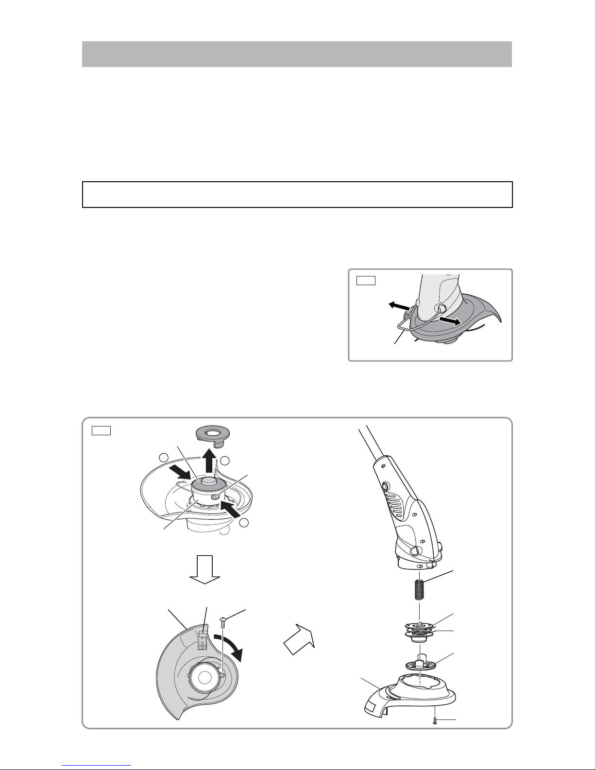
1. Disassembling the housing section
(1) Open the Guide [43] wide and detach it from the housing
as shown in Fig. 1.
(2) Pull up the Upper Cover [49] from the Wire Roll Support [41] while pushing in its two latches together.
Remove the Wire Roll [47] with the nylon wire and Spring (D) [46]. Next, remove the Screws ST4 x 12
[10]. Turn the Protecting Cover [50] in the arrow direction as shown in Fig. 2 to remove it.
[41]
[49]
Latch (2 pcs.)
[47]
[49]
[50]
[10]
[46]
Disassembly of the Model CG 25SC
REPAIR GUIDE
[43]
1
1
2
[50]
[10]
[48]
[51]
-2-
Fig. 3
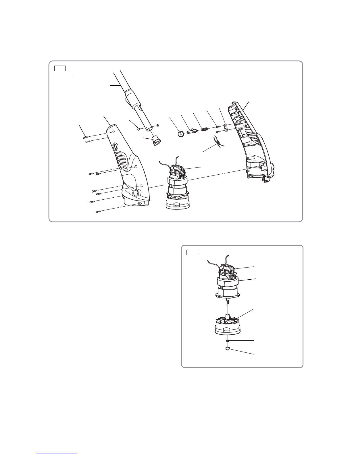
(3) Remove the eight Screws ST4 x 16 [4] from Housing (R) [29] and Housing (L) [35]. Detach the Motor
[39] with the Wire Roll Support [41], Button [32], Lock Pin [33], and Spring (C) [34] as shown in Fig. 3.
(4) Remove the two Screws ST3 x 6 [30] from the Pipe Ass'y [24] to remove the Spacer [31] as shown in
Fig. 3.
2. Removing the motor
(1) Use a hex. bar wrench to turn the Cap [45]
inside the Wire Roll Support [41]. The Cap [45]
comes off together with the M5 Nut [44].
(2) The Wire Roll Support [41] is press-fitted to the
Motor [39]. Use a large bearing puller to remove
it. For easy removal of the support, use the two
side holes of the Wire Roll Support [41] and the
end of the Motor [39] shaft. The Wire Roll
Support [41] is in contact with the ball bearing
of the Motor [39] as shown in Fig. 4.
[4]
[32]
[33]
[34]
[10]
[11]
[38]
[39]
[29]
Fig. 4
[39]
[41]
[44]
[45]
[35]
[30]
[24]
[31]
[40]
-3-
Fig. 6
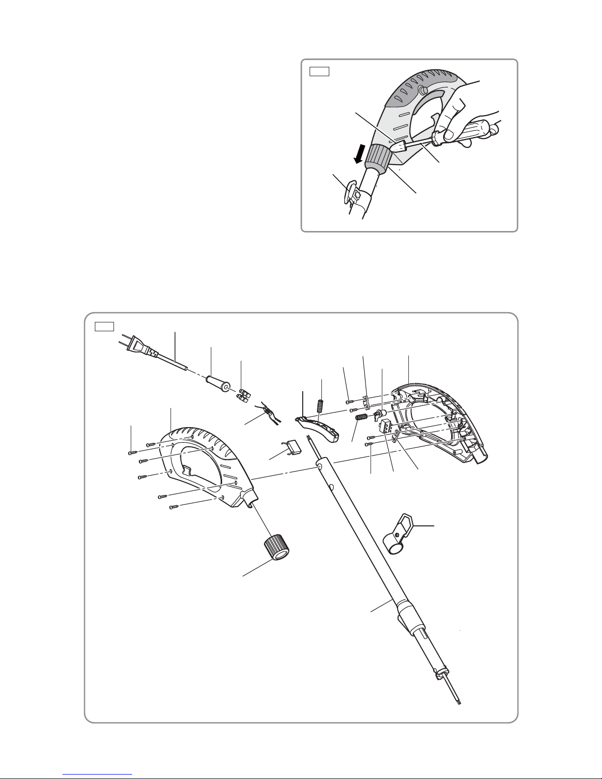
3. Disassembling the handle section
(1) First, remove the Hanger Ass'y [16] and then
use a flat-blade screwdriver to pry off the
Handle Ring [25].
NOTE: Apply a piece of cloth to the flat
end of the screwdriver to protect
parts.
(2) Remove the six Screws ST4 x 16 [4] from Handle (R) [5] and Handle (L) [13]. Remove the Trigger [8],
Spring (A) [9], Spring (B) [14], and the Lock Off Button [12] as shown in Fig. 6.
(3) Remove the two Screws ST4 x 12 [10] from each of the three Cord Clips [11] to remove the Cord [1]
from the body.
Fig. 5
[1]
[2]
[3]
[8]
[9]
[10]
[11]
[12]
[13]
[11]
[16]
[15]
[24]
[25]
[10]
[14]
[7]
[6]
[5]
[4]
[25]
Apply a piece
of cloth here.
Flat-blade screwdriver
[16]
-4-
Fig. 8
Reverse the disassembly procedure to reassemble the Model CG 25SC. However, pay particular attention
to the following.
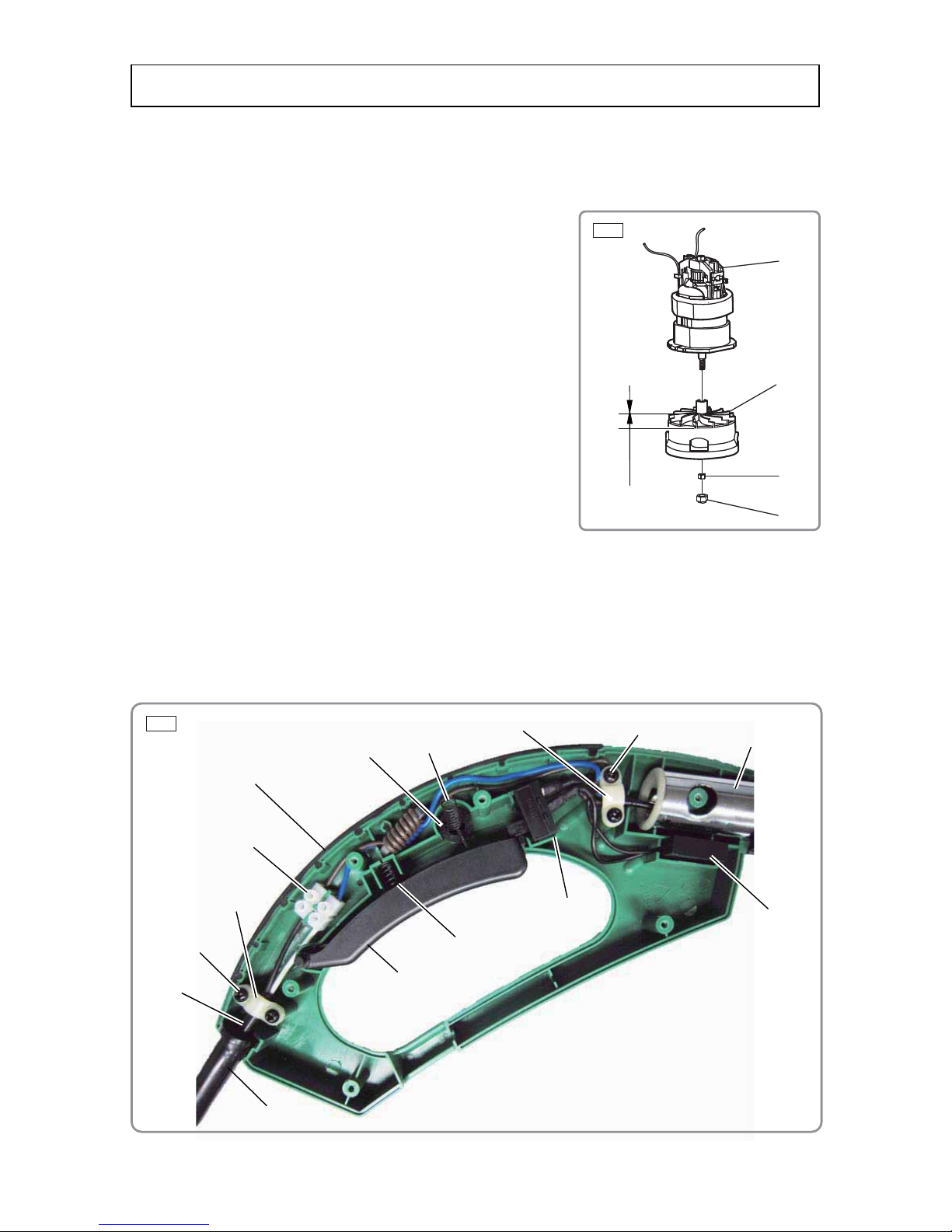
1. Notices on reassembly
(1) Press-fit the Wire Roll Support [41] to the Motor [39] until the
Wire Roll Support [41] contacts the ball bearing of the Motor
[39].
NOTE: Do not press-fit with excessive force. Otherwise,
the Wire Roll Support [41] may be broken.
After press-fitting, put the Cap [45] on the M5 Nut [44] and
tighten it to the shaft of the Motor [39].
NOTE: Do not press-fit with excessive force. Otherwise,
the Cap [45] may fall off.
NOTE: The wire roll support of the Model CG 25SC is
similar to that of the Model CG 30SC but they are
not interchangeable (13.5-mm portion is slightly
different in shape.) Do not mismount.
NOTE: Replace the Wire Roll Support [41] with new one
without fail when replacing the Motor [39].
(2) Mount the Lock Off Button [12] and Spring (B) [14] into Handle (L) [13], and then put Handle (L) [13]
and Handle (R) [5] together aligning the position of Spring (B) [14].
NOTE: When putting Handle (R) [5] and Handle (L) [13] together, completely fit the internal
wires into the grooves of the handle ribs so that the internal wires are not pinched by
the handle bodies.
NOTE: The position of the Lock Off Button [12] is predetermined. Fit the protrusion of the Lock
Off Button [12] in the recessed portion of Handle (L) [13].
[13]
[12]
[14]
Fig. 7
[39]
[41]
[44]
[45]
13.5 mm
[11]
[10]
[2]
[1]
[3]
[8]
[9]
[15]
[24]
[10]
[11]
Reassembly of the Model CG 25SC
[7]

-5-
2. Checking after reassembly
(1) Check that the Lock Off Button [12] can be operated normally. Check that the trimmer does not
operate just by pulling the Trigger [8].
(2) Push the Button [32] and check that Housing (R) [29] and Housing (L) [35] can be turned 180° and
locked correctly .
(3) Check the handle portion (Pipe Ass'y [24]) can be smoothly extended and retracted, and firmly locked.
 Loading...