

Page 1
Model
Modèle
Modelo
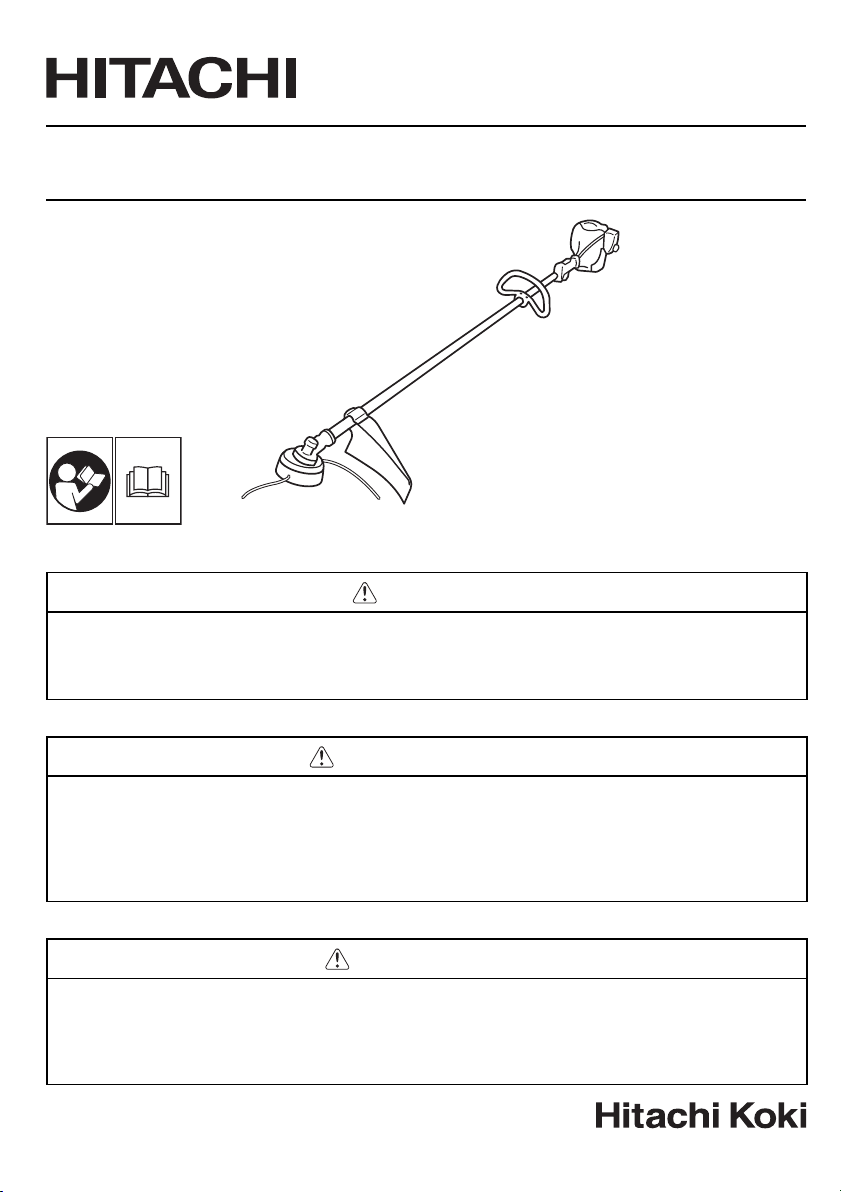
CG 25EUS (L)
Grass Tri m me r/ Br u sh Cutter
Coupe-Herbes/Débroussailleuse
Motoguadañas/Desbrozadoras
SAFETY INSTRUCTIONS AND INSTRUCTION MANUAL
WARNING
IMPROPER OR UNSAFE use of this power tool can result in death or serious bodily injury!
This manual contains important information about product safety. Please read and understand this manual
BEFORE operating the power tool. Please keep this manual available for other users and owners before they
use the power tool. This manual should be stored in safe place.
INSTRUCTIONS DE SECURITE ET MODE D’EMPLOI
AVERTISSEMENT
Une utilisation INCORRECTE OU DANGEREUSE de cet outil motorisé peut entraîner la mort ou de
sérieuses blessures corporelles !
Ce mode d’emploi contient d’importantes informations à propos de la sécurité de ce produit. Prière de
lire et de comprendre ce mode d’emploi AVANT d’utiliser l’outil motorisé. Garder ce mode d’emploi à la
disponibilité des autres utilisateurs et propriétaires avant qu’ils utilisent l’outil motorisé. Ce mode d’emploi
doit être conservé dans un endroit sûr.
INSTRUCCIONES DE SEGURIDAD Y MANUAL DE INSTRUCCIONES
ADVERTENCIA
¡La utilización INAPROPIADA O PELIGROSA de esta herramienta eléctrica puede provocar lesiones
graves o la muerte!
Este manual contiene información importante sobre la seguridad del producto. Lea y comprenda este manual
ANTES de utilizar la herramienta eléctrica. Guarde este manual para que puedan leerlo otras personas
antes de utilizar la herramienta eléctrica. Este manual debe ser guardado en un lugar seguro.
Page 2
English
Meanings of symbols NOTE: Some units do not carry them
Symbols
WARNING
The following show symbols used for the machine. Be sure that you understand their meaning
before use.
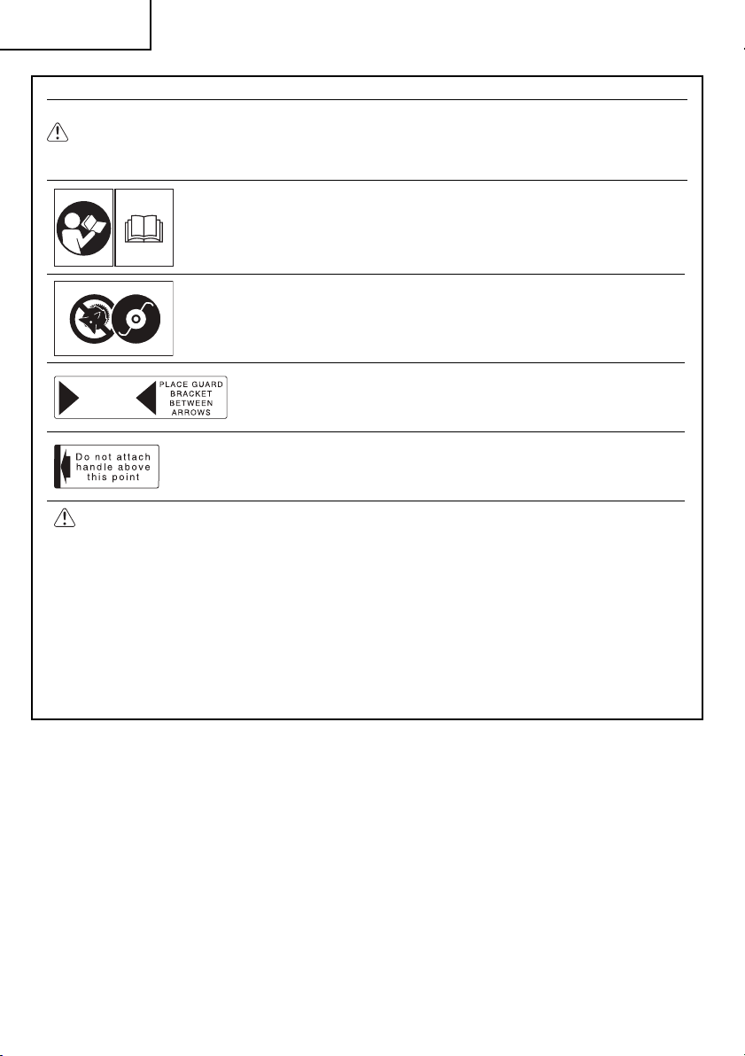
It is important that you read, fully understand and observe the following
safety precautions and warnings. Careless or improper use of the unit
may cause serious or fatal injury.
Do not use metal/rigid blades when this sign is shown on the unit.
Indicates blade guard location for a trimmer head or Brain head.
Indicate handle location. Do not attach handle above this point.
WARNING
● Read the operator’s manual and follow all warnings and safety instructions. Failure to do
so can result in serious injury to the operator and /or bystanders.
● Objects may be thrown or ricochet in all directions. ALWAYS WEAR EYE PROTECTION.
● Keep bystanders at least 50 feet (15 m) away.
● To reduce the chance of hearing loss, always wear ear protection.
● To reduce the risk of injury from loss of control, never use a metal blade on a curved shaft
grass trimmer. Never use a metal blade on any brush cutter without barrier bar or bicycle
handle confi guration and safety strap.
● Use of a blade may cause a sudden sideways, forward or backward motion of the brush
cutter when the blade contacts a solid object. See the owner’s manual for model specifi c
details.
Contents
WHAT IS WHAT? ...................................................3
WARNINGS AND SAFETY INSTRUCTIONS .........4
SPECIFICATIONS ..................................................6
ASSEMBLY PROCEDURES ..................................6
OPERATING PROCEDURES ................................. 8
MAINTENANCE ...................................................11
IMPORTANT NOTICE ..........................................14
2
Page 3
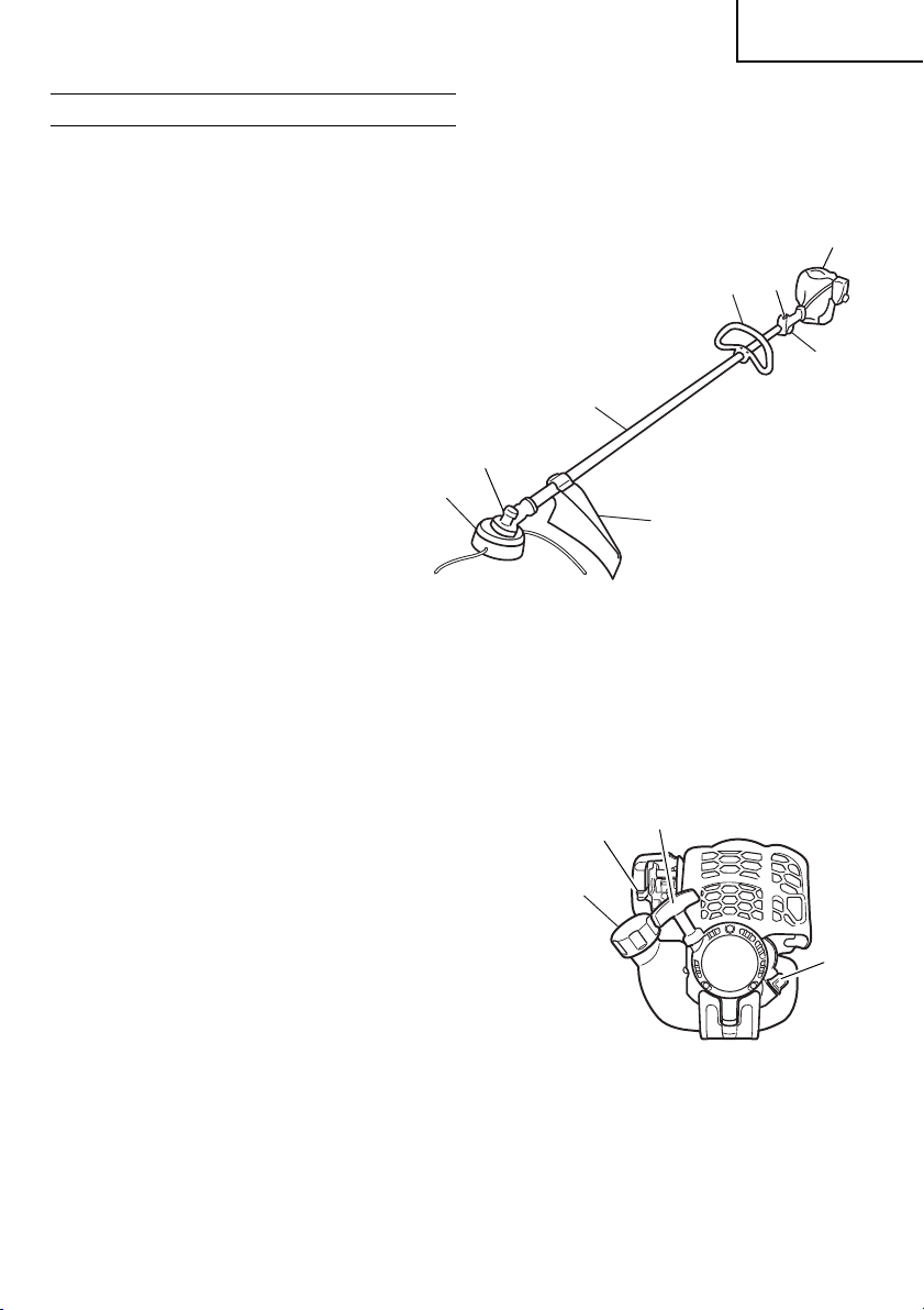
WHAT IS WHAT?
Since this manual covers several models, there may
be some diff erence between these illustrations and
your unit. Use the instructions that apply to your unit.
English
1. Fuel cap
2. Throttle trigger
3. Starter handle
4. Blade guard
5. Cutting attachment
6. Drive shaft tube
7. Handle
8. Ignition switch
9. Choke lever
10. Engine
11. Angle transmission
12. Oil cap
10
8
7
2
6
11
5
4
3
9
1
12
3
Page 4

English
WARNINGS AND SAFETY
INSTRUCTIONS
Operator safety
○ Always wear a safety face shield or goggles.
○ Always wear heavy, long pants, boots and gloves.
Do not wear loose clothing, jewelry, short pants,
sandals or go barefoot.
Secure hair so it is above shoulder length.
○ Do not operate this tool when you are tired,
ill or under the infl uence of alcohol, drugs or
medication.
○ Never let a child or inexperienced person operate
the machine.
○ Wear hearing protection. Pay attention to your
surroundings. Be aware of any bystanders who
may be signaling a problem. Remove safety
equipment immediately upon shutting off engine.
○ Wear head protection.
○ Never start or run the engine inside a closed room
or building. Breathing exhaust fumes can kill.
○ Keep handles free of oil and fuel.
○ Keep hands away from cutting equipment.
○ Do not grab or hold the unit by the cutting
equipment.
○ When the unit is turned off , make sure the cutting
attachment has stopped before the unit is set
down.
○ When operation is prolonged, take a break from
time to time so that you may avoid possible Hand-
Arm Vibration Syndrome (HAVS) which is caused
by vibration.
WARNING
● Antivibration systems do not guarantee that
you will not sustain HAVS or carpal tunnel
syndrome. Therefore, continual and regular
users should monitor closely the condition
of their hands and fi ngers. If any symptoms
of the above appear, seek medical advice
immediately.
● If you are using any medical electric/electronic
devices such as a pacemaker, consult your
physician as well as the device manufacturer
prior to operating any power equipment.
Unit/machine safety
○ Inspect the entire unit/machine before each use.
Replace damaged parts. Check for fuel leaks and
make sure all fasteners are in place and securely
tightened.
○ Replace parts that are cracked, chipped or
damaged in any way before using the unit/
machine.
○ Make sure the safety guard is properly attached.
○ Keep others away when making carburetor
adjustments.
○ Use only accessories as recommended for this
unit/machine by the manufacturer.
WARNING
Never modify the unit/machine in any way. Do
not use your unit/machine for any job except
that for which it is intended.
Fuel safety
○ Pour fuel outdoors and where there are no sparks
or fl ames.
○ Use a container approved for fuel and oil.
○ Do not smoke or allow smoking near fuel or the
unit/machine or while using the unit/machine.
○ Wipe up all fuel spills before starting engine.
○ Move at least 10 ft (3 m) away from fueling site
before starting engine.
○ Stop engine before removing fuel cap and oil cap.
○ Empty the fuel tank before storing the unit/
machine. It is recommended that the fuel be
emptied after each use. If fuel is left in the tank,
store so fuel will not leak.
○ Store unit/machine and fuel in area where fuel
vapors cannot reach sparks or open fl ames
from water heaters, electric motors or switches,
furnaces, etc.
WARNING
Fuel is easy to ignite or get explosion or
inhale fumes, so that pay special attention
when handling or fi lling fuel.
Cutting safety
○ Do not cut any material other than grass and
brush.
○ Inspect the area to be cut before each use.
Remove objects which can be thrown or become
entangled.
○ For respiratory protection, wear an aerosol
protection mask when cutting the grass after
insecticide is scattered.
○ Keep others including children, animals,
bystanders and helpers outside the 16 ft. (5 m)
hazard zone. Stop the engine immediately if you
are approached.
○ Always keep the engine on the right side of your
body.
○ Hold the unit/machine fi rmly with both hands.
○ Keep fi rm footing and balance. Do not over-
reach.
○ Keep all parts of your body away from the muffl er
and cutting attachment when the engine is
running.
○ Keep cutting attachment below waist level.
4
Page 5

English
○ When relocating to a new work area, be sure to
shut off the machine and ensure that all cutting
attachments are stopped.
○ Never place the machine on the ground when
running.
○ Always ensure that the engine is shut off and any
cutting attachments have completely stopped
before clearing debris or removing grass from the
cutting attachment.
○ Always carry a fi rst-aid kit when operating any
power equipment.
○ Never start or run the engine inside a closed room
or building and/or near the infl ammable liquid.
Breathing exhaust fumes can kill.
Maintenance safety
○ Maintain the unit/machine according to
recommended procedures.
○ Disconnect the spark plug before performing
maintenance except for carburetor adjustments.
○ Keep others away when making carburetor
adjustments.
○ Use only genuine HITACHI replacement parts as
recommended by the manufacturer.
Transport and storage
○ Carry the unit/machine by hand with the engine
stopped and the muffl er away from your body.
○ Allow the engine to cool, empty the fuel tank,
and secure the unit/machine before storing or
transporting in a vehicle.
○ Empty the fuel tank before storing the unit/
machine. It is recommended that the fuel be
emptied after each use. If fuel is left in the tank,
store so fuel will not leak.
○ Store unit/machine out of the reach of children.
○ Clean and maintain the unit carefully and store it
in a dry place.
○ Make sure engine switch is off when transporting
or storing.
○ When transporting in a vehicle, cover blade with
blade cover.
CAUTION
Indicates a possibility of personal injury or
equipment damage if instructions are not
followed.
NOTE
Helpful information for correct function and use.
CAUTION
Do not disassemble the recoil starter. You
may get a possibility of personal injury with
recoil spring.
If situations occur which are not covered in this
manual, take care and use common sense. Contact
HITACHI dealer if you need assistance. Pay special
attention to statements preceded by the following
words:
WARNING
Indicates a strong possibility of severe
personal injury or loss of life if instructions
are not followed.
5
Page 6
English
SPECIFICATIONS
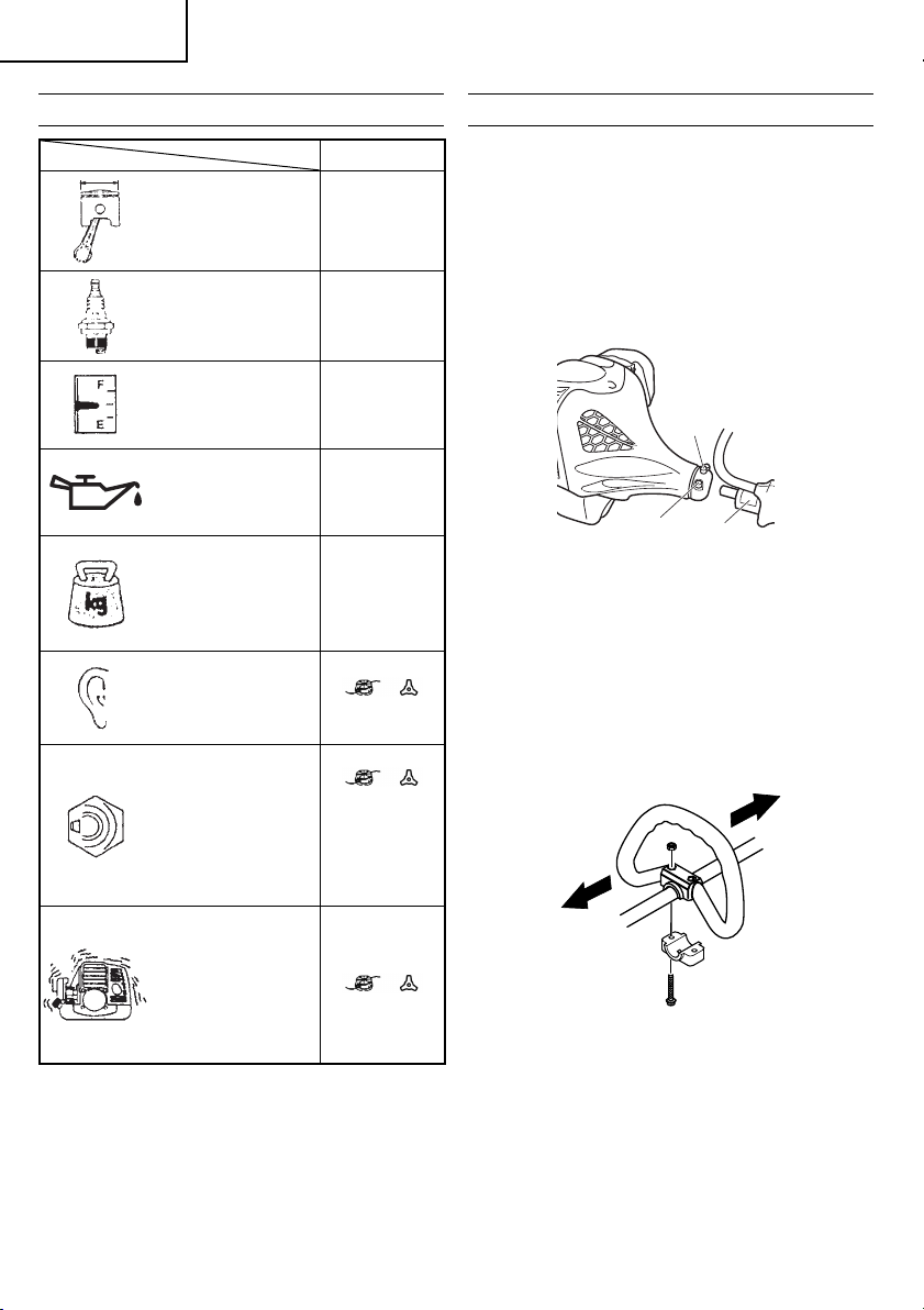
Engine Size
(cu. in.)
Spark Plug
Fuel Tank Capacity
(fl . oz)
Engine Oil Capacity
(fl . oz)
Dry Weight (lbs) 11.0 (5.0 kg)
Sound pressure
level
LpA (dB (A))
(EN27917)
Measured sound
power level LwA
(dB (A))
Model CG25EUS (L)
1.53 (25 mℓ)
NGK CMR5H
or equivalent
16.7 (0.5ℓ)
2.7 (80 mℓ)
81.8 78.6
101.8 98.6
ASSEMBLY PROCEDURES
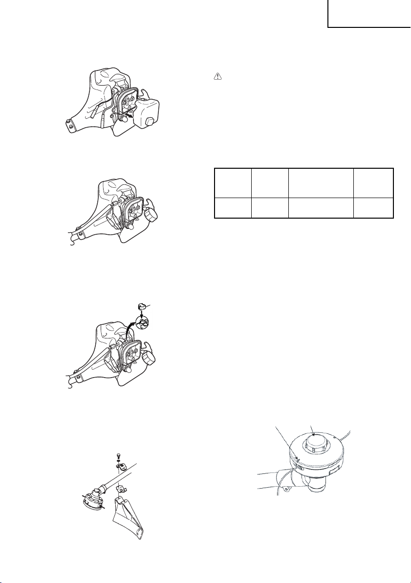
Drive shaft to engine (Fig. 1)
Loosen tube locking bolt (1) so that the bolt point will
not obstruct drive shaft tube to be inserted. When
inserting drive shaft tube, hold the tube locking bolt
outward preventing inside fi tting from obstructing as
well.
Insert the drive shaft into the clutch case of the
engine properly until the marked position (2) on the
drive shaft tube meets the clutch case.
1
3
2
Fig. 1
NOTE
○ When it is hard to insert drive shaft up to the
marked position on the drive shaft tube, turn drive
shaft by the cutter mounting end clockwise or
counter-clockwise. Tighten tube locking bolt lining
up the hole in the shaft tube.
Then tighten clamp bolt securely (3).
Installation of handle (Fig. 2)
Guaranteed sound
power level LwA
(dB (A))
Vibration level
(m/s2) (ISO7916)
Front handle
Rear handle
NOTE
Equivalent noise level/vibration level are
calculated as the time-weighted energy total
for noise/vibration levels under various working
conditions with the following time distribution: 1/2
Idle, 1/2 racing.
* All data is subject to change without notice.
6
104 101
4.8 4.5
3.2 4.6
Fig. 2
Attach the handle to the drive shaft tube with the
angle towards the engine.
Adjust the location to the most comfortable position
before operation.
NOTE
If your unit has handle location label on drive shaft
tube, follow indication.
Page 7
English
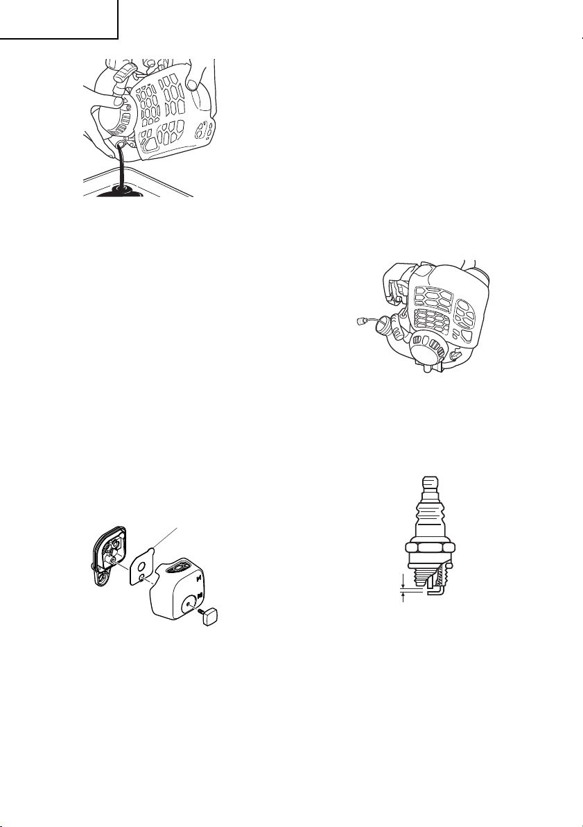
Throttle wire/stop cord
Remove air cleaner cover. (Fig. 3)
Fig. 3
Connect stop cords. (Fig. 4)
Fig. 4
Connect throttle wire end to carburetor and install
swivel cap (4) (if so equipped) where is included in
tool bag, onto swivel. (Fig. 5)
4
Fig. 5
NOTE
If your unit has guard location label on drive shaft
tube, follow the indication.
CAUTION
● Some blade guards are equipped with sharp
line limiters. Be careful with handling it.
Installation of semi-auto cutting head
1. Function
Automatically feeds more nylon cutting line when
it is tapped at low rpm (not greater than 4,500
rpm).
Specifi cations
Code
6696454
Applicable nylon cord
2. Precautions
○ The case must be securely attached to the cover.
○ Check the cover, case and other components for
○ Check the case and button for wear.
If the wear limit mark on the case is no longer
○ The cutting head must be securely mounted to the
○ For outstanding performance and reliability,
Type of
attaching
No.
screw
Female
screw
Cord diameter: 0.12 in. (Φ3.0 mm)
Length: 6.56 ft. (2 m)
Cord diameter: 0.10 in. (Φ2.4 mm)
Length: 13.12 ft. (4 m)
cracks or other damage.
visible or there is a hole in the bottom of the button,
change the new parts immediately. (Fig. 7)
unit’s gear case.
always use Hitachi nylon cutting line. Never
use wire or other materials that could become a
dangerous projectile.
Direction of
rotation
Counterclockwise
Size of
attaching
screw
M10×
P1.25-LH
Attach the air cleaner cover.
Installation of blade guard (Fig. 6)
Install the blade guard as shown in Fig. 6.
Fig. 6
5
○ If the cutting head does not feed cutting line
properly, check that the nylon line and all
components are properly installed. Contact your
Hitachi dealer if you need assistance.
6
Fig. 7
7
Page 8
English
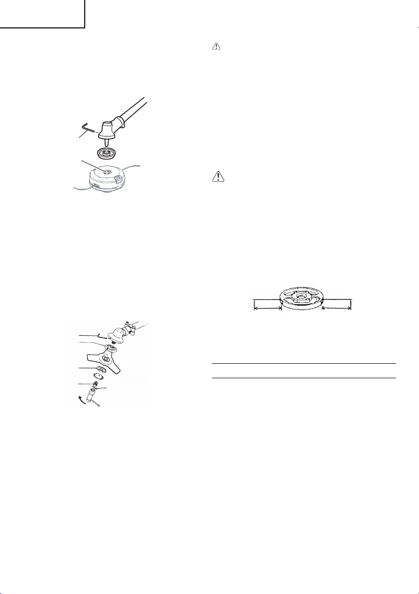
3. Installation (Fig. 8)
○ Install cutting head on gear case of grass
trimmers/brush cutters. The mounting nut (7) is
left-hand-threaded. Turn clockwise to loosen/
counterclockwise to tighten.
8
7
Fig. 8
NOTE
○ Since the cutter holder cap is not used here, keep
it for when a metal blade is used, if so equipped.
○ Insert Allen wrench (8) into the hole of the gear
case in order to lock the cutter holder.
Installation of cutting blade (Fig. 9)
(If so equipped)
When installing a cutting blade, make sure that there
are no cracks or any damage to it and that the cutting
edges are facing the correct direction.
10
11
9
12
NOTE
○ When installing cutter holder cap (9), be sure to
set concave side upward.
Insert the allen wrench (10) into the hole of the
angle transmission in order to lock the cutter
holder (11). Please note that the cutter fi xing bolt
or nut (12) has left-handed threads, (clockwise to
loosen/counter-clockwise to tighten). Tighten the
fi xing bolt or nut with the box wrench.
○ If your unit is of a nut securing type and equipped
with a cotter pin, the blade must be retained with a
new cotter pin (13) each time installed.
13
Fig. 9
CAUTION
● Before operation, make sure the blade has
been properly installed.
● If your unit is equipped with protection cover
under a cutting blade, check it for wear or
cracks before operation. If any damage or
wear is found, replace it, as it is an article of
consumption.
Installation of
NOTE
For installation see your BRAIN owner’s manual,
provided with the BRAIN cutting head.
the BRAIN cutting head
WARNING
For HITACHI BRAIN heads or HITACHI alloy
head, use only fl exible, non-metallic line
recommended by the manufacturer. Never
use wire or wire ropes. They can break off
and become a dangerous projectile.
NOTE
When using HITACHI alloy head (CH-100), initial
cutting line length should be about 6-11/16˝
(17 cm) each. (Fig. 10)
6-11/16˝ (17 cm)
OPERATING PROCEDURES
Engine oil
○ Always use the specifi ed engine oil (multigrade oil
of classifi cation SAE 10W-30). Insuffi cient engine
oil or using engine oil other than the specifi ed type
may cause breakdown of the unit.
Filling up with engine oil
○ Place the unit horizontally on a clean, fl at surface.
○ Remove the oil cap and check whether the engine
oil comes up to the mouth of the oil tank opening.
(Fig. 11)
6-11/16˝ (17 cm)
CH-100
Fig. 10
8
Page 9

English
1.
Set ignition switch (14) to ON position. (Fig. 12)
14
Fig. 11
○ If the oil level is low or when using the unit for the
fi rst time, fi ll the oil tank with engine oil up to the
mouth of the oil tank opening.
○ If the engine oil is conspicuously dirty or discolored,
change the oil.
○ Tighten the oil cap securely after fueling.
○ When using the unit for the fi rst time, change
the engine oil after running the engine for
approximately 10 hours. Subsequently, change
the oil after every 50 hours of operation.
CAUTION
● To avoid the risk of burn injury, allow the
engine to cool thoroughly before changing
the engine oil.
● To prevent breakdown, ensure that no sand
or dirt gets into the oil tank while refueling.
Fuel
○ Always use branded 89 octane unleaded
gasoline.
○ Do not use a mixture of gasoline and engine oil as
this may lead to starter failure or power reduction.
Fueling
WARNING
● Always shut off the engine before refueling.
● Slowly open the fuel tank, when fi lling up
with fuel, so that possible overpressure
disappears.
● Tighten the fuel cap carefully, after fueling.
● Always move the trimmer at least 10 ft. (3 m)
from the fueling area before starting.
Before fueling, clean the tank cap area carefully, to
ensure that no dirt falls into the tank.
Starting (Fig. 12)
CAUTION
Before starting, make sure the cutting
attachment does not touch anything.
Fig. 12
* Push priming bulb (15) several times so that fuel
fl ows through return pipe. (If so equipped) (Fig.
13)
15
16
Fig. 13
2. Set choke lever to CLOSED position (16). (Fig.
13)
3. Pull recoil starter briskly, taking care to keep the
handle in your grasp and not allowing it to snap
back. (Fig. 14)
Fig. 14
4. When you hear the engine want to start, return
choke lever to RUN position (open). Then pull
recoil starter briskly again.
NOTE
If engine does not start, repeat procedures from 2
to 4.
5. After starting engine, allow the engine about 2–3
minutes to warm up before subjecting it to any
load.
9
Page 10
English
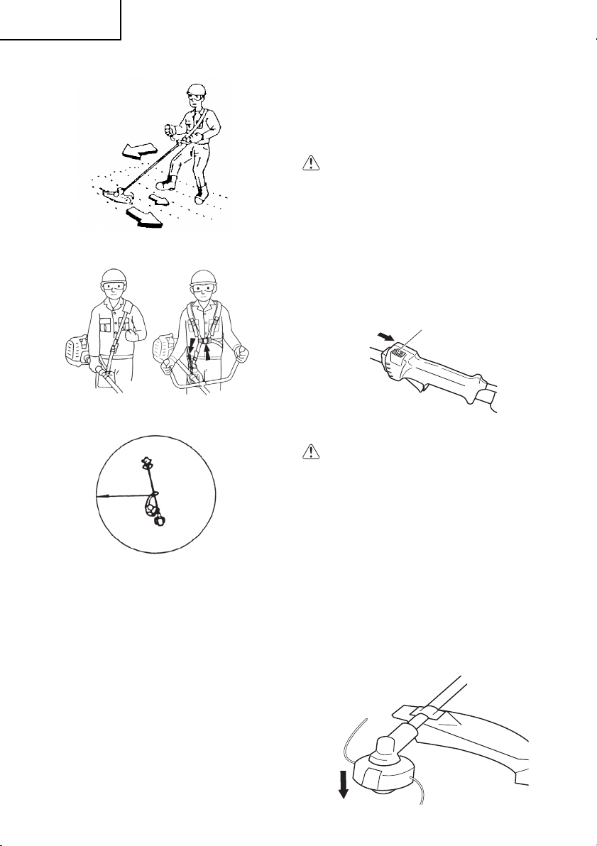
Cutting (Fig. 15, 16, 17)
Fig. 15
Fig. 16
50 ft
(15 m)
Fig. 17
○ When cutting, operate engine at over 6,500/min.
Extended time of use at low rpm may wear out the
clutch prematurely.
○ Cut grass from right to left.
○ Blade thrust may occur when the spinning blade
contacts a solid object in the critical area.
A dangerous reaction may occur causing the
entire unit and operator to be thrust violently. This
reaction is called blade thrust. As a result, the
operator may lose control of the unit which may
cause serious or fatal injury. Blade thrust is more
likely to occur in areas where it is diffi cult to see
the material to be cut.
○ Wear the harness as shown in the fi gure (if so
equipped). The blade turns counterclockwise,
therefore, be advised to operate the unit from right
10
to left for effi cient cutting. Keep onlookers out of
working area at least 50 ft. (15 m).
NOTE
Press the quick release button or pull emergency
release fl ap (If so equipped) in the event of
emergency.
WARNING
If cutting attachment should strike against
stones or other debris, stop the engine and
make sure that the attachment and related
parts are undamaged. When grass or vines
wrap around attachment, stop engine and
attachment and remove them.
Stopping (Fig. 18)
○ Decrease engine speed and run at an idle for a
few minutes, then turn off ignition switch (17).
17
Fig. 18
WARNING
A cutting attachment can injure while it
continues to spin after the engine is stopped
or power control is released. When the unit is
turned off , make sure the cutting attachment
has stopped before the unit is set down.
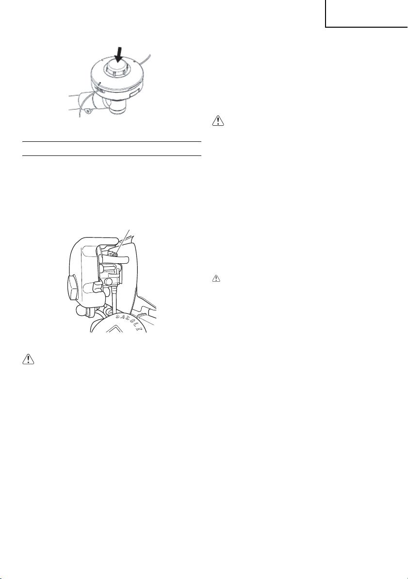
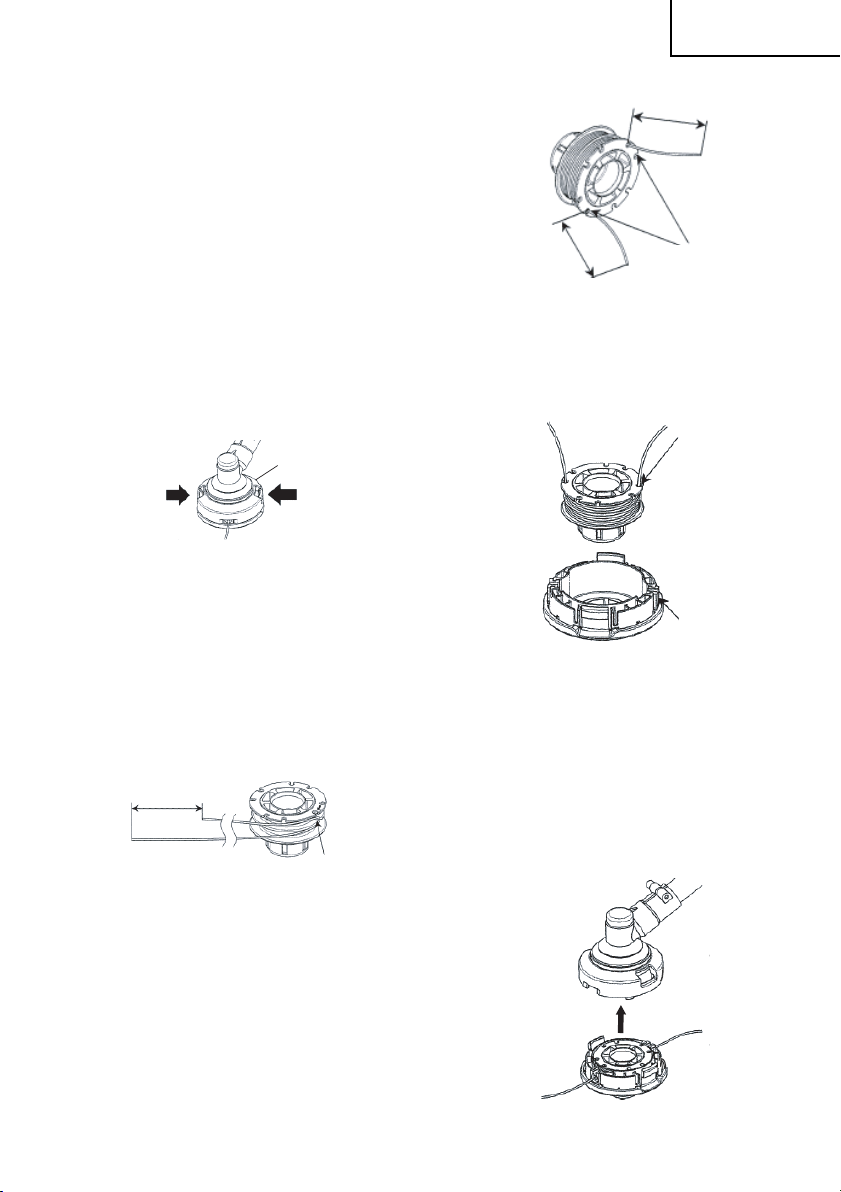
Semi-auto cutting head
Adjusting line length
○ Set the engine speed as low as possible and tap
the head on the ground. The nylon line will be
drawn out about 3 cm with each tap. (Fig. 19)
Also, you can extend the nylon line by hand but
the engine must be completely stopped. (Fig. 20)
○ Adjust the nylon line to the proper length of 11–14
cm before each operation.
Fig. 19
Page 11
English
the correct idle speed when the engine runs smoothly
in all positions well below the rpm when the cutting
attachment starts to rotate.
If the cutting attachment still rotates after idle speed
adjustment, contact HITACHI dealer.
NOTE
Standard idle rpm is 3,000/min.
Fig. 20
MAINTENANCE
MAINTENANCE, REPLACEMENT OR REPAIR
OF THE EMISSION CONTROL DEVICES AND
SYSTEMS MAY BE PERFORMED BY ANY NONROAD ENGINE REPAIR ESTABLISHMENT OR
INDIVIDUAL.
Carburetor adjustment (Fig. 21)
T
Fig. 21
WARNING
● The cutting attachment may be spinning
during carburetor adjustments.
● Never start the engine without the complete
fan case and tube assembled! Otherwise the
clutch can come loose and cause personal
injuries.
In the carburetor, fuel is mixed with air. When the
engine is test run at the factory, the carburetor is
basically adjusted. A further adjustment may be
required, according to climate and altitude. The
carburetor has one adjustment possibility:
T = Idle speed adjustment screw.
Idle speed adjustment (T)
Check that the air fi lter is clean. When the idle speed
is correct, the cutting attachment will not rotate. If
adjustment is required, close (clockwise) the T-screw,
with the engine running, until the cutting attachment
starts to rotate. Open (counter-clockwise) the screw
until the cutting attachment stops. You have reached
WARNING
When the engine is idling the cutting
attachment must under no circumstances
rotate.
NOTE
Some models sold areas with strict exhaust
emission regulation do not have high and low
speed carburetor adjustments. Such adjustments
may allow the engine to be operated outside of
their emission compliance limits. For these models,
the only carburetor adjustment is idle speed.
Changing the engine oil
Dirty engine oil will considerably reduce the service
life of the engine. Check and change the engine oil
regularly.
CAUTION
● To avoid risk of burn injury, allow the engine
to cool thoroughly before changing the
engine oil.
● To prevent breakdown, ensure that no sand
or dirt gets into the tank while refueling.
When to change the oil: When fi rst using the unit, after
approximately 10 hours of operation or after 1 month,
whichever occurs earlier; subsequently, after every
50 hours of operation or every 6 months, whichever
occurs earlier.
Specifi ed engine oil: Multigrade oil of classifi cation SAE
10W-30
Engine oil capacity: 4.88 cu. in. (80 ml)
1. Turn off the ignition switch.
2. Check that the fuel cap is securely tightened.
3. Remove the oil cap, tilt the unit so that the oil tank
opening is on the underside and drain the engine
oil into a container. (Fig. 22)
11
Page 12
English
Fig. 22
4. When all the engine oil has been drained, place
the unit horizontally on a clean, fl at surface.
5. Fill the oil tank with engine oil up to the mouth of
the oil tank opening. (Fig. 11)
6. Tighten the oil cap securely by hand.
NOTE
○ Do not dispose of waste engine oil with garbage
or into the ground.
Dispose of the oil according to the specifi ed
method in your area.
If you are unsure, contact the retailer where the oil
was purchased.
○ Fill the oil tank with the specifi ed amount of engine
oil.
Too much or too little engine oil may result in
engine breakdown.
○ Engine oil deteriorates naturally even if unused.
Change the engine oil regularly.
Air fi lter (Fig. 23)
Cleaning the air fi lter
Remove the air fi lter cover and the fi lter (18). Rinse it
in warm soap suds. Check that the fi lter is dry before
reassembly. An air fi lter that has been used for some
time cannot be cleaned completely. Therefore, it must
regularly be replaced with a new one. A damaged
fi lter must always be replaced.
Fuel fi lter (Fig. 24)
Drain all fuel from fuel tank and pull fuel fi lter line from
tank. Pull fi lter element out of holder assembly and
rinse element in warm water with detergent.
Rinse thoroughly until all traces of detergent are
eliminated. Squeeze, do not wring, away excess
water and allow element to air dry.
Fig. 24
NOTE
If element is hard due to excessive dirt buildup,
replace it.
Spark plug (Fig. 25)
18
Fig. 23
The air fi lter must be cleaned from dust and dirt in
order to avoid:
○ Carburetor malfunctions.
○ Starting problems.
○ Engine power reduction.
○ Unnecessary wear on the engine parts.
○ Abnormal fuel consumption.
Clean the air fi lter daily or more often if working in
exceptionally dusty areas.
12
.024˝
(0.6 mm)
Fig. 25
The spark plug condition is infl uenced by:
○ An incorrect carburetor setting.
○ A dirty air fi lter.
○ Hard running conditions (such as cold weather).
○ Too much engine oil
These factors cause deposits on the spark plug
electrodes, which may result in malfunction and
starting diffi culties. If the engine is low on power,
diffi cult to start or runs poorly at idling speed, always
check the spark plug fi rst. If the spark plug is dirty,
Page 13
English
clean it and check the electrode gap. Readjust if
necessary. The correct gap is .024˝ (0.6 mm). The
spark plug should be replaced after about 100
operation hours or earlier if the electrodes are badly
eroded.
NOTE
In some areas, local law requires using a resistor
spark plug to suppress ignition signals. If this
machine was originally equipped with resistor
spark plug, use same type of spark plug for
replacement.
Semi-auto cutting head
Nylon line replacement
(1) Remove the case (19) by fi rmly pushing inward
the locking tabs with your thumbs as shown in Fig.
26.
19
Fig. 26
(2) After removing the case, take out the reel and
discard the remaining line.
(3) Fold the new nylon line unevenly in half as shown
in picture.
Hook the U-shaped end of the nylon line into the
groove (20) on the center partition of the reel.
Wind both halves of the line on the reel in the
same direction, keeping each half of the line on its
own side of the partition. (Fig. 27)
4˝ (10 cm)
4˝ (10 cm)
21
Fig. 28
(5) Insert both loose ends of the line through the cord
guide (22) when placing the reel in the case. (Fig.
29)
21
22
Fig. 29
NOTE
When placing a reel in the case, try to line up the
stopper holes (21) with the cord guide (22) for
easier line release later.
4˝ (10 cm)
20
Fig. 27
(4) Push each line into the stopper holes (21), leaving
the loose ends approx. 4˝ (10 cm) in length.
(Fig. 28)
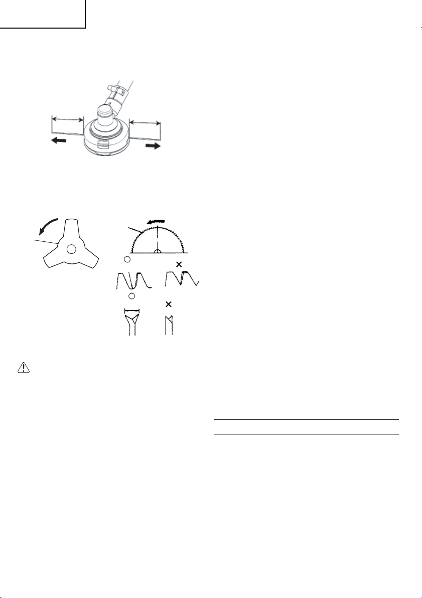
(6) Place the cover over the case so that the cap
locking tabs on the case meet the long holes on
the cover. Then push the case securely until it
clicks into place. (Fig. 30)
Fig. 30
13
Page 14
English
(7) The initial cutting line length should be approx.
4-11/32˝–5-1/2˝ (11-14 cm) and should be equal
on both sides. (Fig. 31)
4-11/32˝–5-1/2˝
(11-14 cm)
Blade (Fig. 32)
23
4-11/32˝–5-1/2˝
(11-14 cm)
Fig. 31
24
R1 – 1.5 mm
1.9 – 2.2 mm
Fig. 32
WARNING
Wear protective gloves when handling or
performing maintenance on the blade.
○ Use a sharp blade. A dull blade is more likely to
snag and thrust. Replace the fastening nut if it is
damaged and hard to tighten.
○ When replacing blade, purchase one
recommended by HITACHI, with a 1˝ (25.4 mm)
fi tting hole.
○ When installing saw blade (24), always face the
stamped side up. In the case of a 4-tooth blade
(23), it can be used on either side.
○ Use correct blade for the type of work.
○ When replacing blade, use appropriate tools.
○ When cutting edges become dull, re-sharpen or
fi le as shown in fi gure. Incorrect sharpening may
cause excessive vibration.
○ Discard blades that are bent, warped, cracked,
broken or damaged in any way.
NOTE
When sharpening blades it is important to maintain
an original shape of radius at the base of the tooth
to avoid cracking.
Maintenance schedule
Below you will fi nd some general maintenance
instructions. For further information please contact
your HITACHI dealer.
Daily maintenance
○ Clean the exterior of the unit.
○ Check that the harness is undamaged.
○ Check the blade guard for damage or cracks.
Change the guard in case of impacts or cracks.
○ Check that the cutting attachment is properly
centred, sharp, and without cracks. An off - centred
cutting attachment induces heavy vibrations that
may damage the unit.
○ Check that the cutting attachment nut is suffi ciently
tightened.
○ Make sure that the blade transport guard is
undamaged and that it can be securely fi tted.
○ Check that nuts and screws are suffi ciently
tightened.
○ Check the volume and condition of the engine oil.
Weekly maintenance
○ Check the starter, especially cord and return
spring.
○ Clean the exterior of the spark plug.
○ Remove the spark plug and check the electrode
gap. Adjust it to .024˝ (0.6 mm), or change the
spark plug.
○ Clean the air fi lter.
Monthly maintenance
○ Rinse the fuel tank with gasoline.
○ Clean the exterior of the carburetor and the space
around it.
○ Clean the fan and the space around it.
IMPORTANT NOTICE
THIS INFORMATION IS FOR THE US AND
CANADIAN MARKETS ONLY.
○ Never use a metal blade on any brush cutter
without barrier bar or bicycle handle confi guration
and safety strap and a safety guard specifi cally
designed and approved for blade use.
○ Use only attachments or accessories designed for
your unit and off ered by HITACHI. Although some
unauthorized parts may be adaptable, their use
may be extremely dangerous and could cause
serious injury or death.
14
Page 15

HITACHI off ers a complete line of trimmer/brush
cutter accessories to accomplish any job while
ensuring safe operation.
The following models are sold as grass trimmers
capable of being converted to blade-capable brush
cutters: CG25EUS (L)
Blade adapter kits for this model can be purchased
at your local HITACHI dealer. These kits contain
a safety barrier bar and shoulder strap as well as
the necessary blade guard and blade mounting
hardware.
WARNING
The blade conversion kit MUST be used when
operating these models with steel blades.
Never install a steel blade without the use of
the blade-securing cotter pins included in the
kit. Proper installation of all blade-mounting
components is required when converting
a grass trimmer to a blade-capable brush
cutter. Consult your Tanaka dealer if you are
uncertain about any aspect of blade use on
your Tanaka unit.
Bicycle Style Handle Kit #748502
This kit converts model CG25EUS (L) from “D” style
front handles to dual handled style brush cutters.
English
15
Page 16

Français
Signifi cation des symboles REMARQUE : Certaines machines n’en sont pas pourvues
Symboles
AVERTISSEMENT
Les symboles suivants sont utilisés pour l’outil. Bien se familiariser avec leur signifi cation avant
d’utiliser l’outil.
II est essentiel que vous lisiez et compreniez parfaitement les
consignes de sécurités et autres avertissements suivants et que vous
les observiez strictement. L’utilisation inattentive ou inadéquate de
cette machine risque de provoquer des blessures graves ou fatales.
Ne pas utiliser de lames métalliques/rigides lorsque ce signe apparaît
sur la machine.
Indique l’emplacement du carter de protection de la lame pour une
tête à fi l nylon ou pour une tête automatique BRAIN.
Indique l’emplacement du guidon. Ne pas positionner le guidon audessus de ce point.
AVERTISSEMENT
● Lire attentivement le Manuel et respecter l’ensemble des mises en garde et consignes
de sécurité. Négliger cet avertissement peut exposer l’opérateur et/ou les personnes
présentes alentour à des blessures sévères.
● Il se peut que des objets soient lancés ou ricochent en tous sens. PORTER TOUJOURS
DES LUNETTES DE SÉCURITÉ.
● Éloigner les badauds jusqu’à une distance d’au moins de 50 pieds (15 mètres).
● Porter toujours des pare-oreilles pour éviter la possibilité d’une perte auditive.
● Ne jamais utiliser une lame métallique attachée à un coupe-herbes à l’arbre courbé pour
ne pas courir le risque de blessure à cause d’une perte de commande. Ne jamais employer
une lame métallique attachée à une débroussailleuse sans un barreau protecteur ou sans
une confi guration de guidon avec une bandoulière de sûreté.
● L’emploi d’une lame peut occasionner des mouvements soudains en avant, de côté ou en
arrière de la débroussailleuse lorsque la lame entre en contact avec un objet solide. Voir
le manuel de propriétaire pour des détails spécifi ques sur les modèles.
Table des matières
DESCRIPTION .....................................................17
PRÉCAUTIONS ET CONSIGNES DE SÉCURITÉ
CARACTÉRISTIQUES .........................................20
MONTAGE ...........................................................20
UTILISATION ........................................................23
ENTRETIEN .........................................................25
AVIS IMPORTANT................................................29
16
...18
Page 17

DESCRIPTION
Comme ce manuel se réfère à plusieurs modèles, il
se peut qu’il y ait des diff érences entre les images
et votre machine. Suiver les instructions concernant
votre modèle.
1. Bouchon de remplissage du carburant
2. Levier de commande des gaz
3. Poignée de démarrage
4. Carter de protection de la lame
5. Outil de coupe
6. Tube d’arbre de transmission
7. Guidon
8. Interrupteur marche-arrêt
9. Levier de starter
10. Moteur
11. Boîtier de renvoi d’angle
12. Bouchon d’huile
5
11
Français
10
8
7
2
6
4
3
9
1
12
17
Page 18

Français
PRÉCAUTIONS ET CONSIGNES
DE SÉCURITÉ
Sécurité de l’utilisateur
○ Portez toujours une visière et des lunettes de
protection.
○ Portez toujours un pantalon, des chaussures
et des gants de sécurité. Evitez les vêtements
amples, les bjioux, les shorts, les sandales et
les pieds nus. Veillez à ce que vos cheveux ne
descendent pas au-dessous des épaules.
○ N’utilisez cette machine que si vous êtes en pleine
possession de vos moyens physiques. Evitez
strictement la consommation d’alcool, de drogue
ou de médicaments.
○ Ne laissez jamais un enfant ou une personne
inexpérimentée se servir de la machine.
○ Portez un dispositif de protection contre le bruit
pour vos oreilles. Restez vigilant à tout ce qui
vous entoure. Soyez attentif dans l’éventualité où
une personne située à proximité vous signalerait
un problème. Retirez les équipements de sécurité
immédiatement après avoir coupé le moteur de
l’appareil.
○ Protégez-vous la tête.
○ Ne mettez jamais le moteur en marche dans un
local clos, les gaz d’échappement étant toxiques.
○ Nettoyez les poignées de toute trace d’huile ou de
carburant.
○ N’approchez jamais les mains de l’outil de
coupe.
○ N’attrapez pas ni ne tenez la machine par l’outil de
coupe.
○ Après l’arrêt de la machine, attendez l’arrêt
complet de l’outil de coupe avant de poser la
machine.
○ Lors d’une utilisation prolongée, veillez à faire une
pause périodiquement, afi n d’éviter des troubles
éventuels provoqués par les vibrations.
AVERTISSEMENT
● Les systèmes anti-vibrations, aussi bon
soient-ils, ne garantissent pas que vous
ne puissiez pas souff rir de la maladie des
doigts blancs, ni du syndrome du canal
carpien. Par conséquent, si vous vous servez
de façon régulière et continue de votre
machine, surveillez soigneusement l’état
de vos mains et de vos doigts. Si l’un des
symptômes ci-dessus venait à apparaître, il
serait indispensable de vous faire examiner
immédiatement par votre médecin.
● Si vous êtes équipé d’un appareillage
médical électrique/électronique (par ex. un
pacemaker), consultez votre médecin et le
fabricant de cet appareillage avant d’utiliser
tout appareil électrique/ thermique.
Règles de
machine
○ Contrôlez entièrement votre machine avant
○ Remplacez les pièces de la machine qui
○ Vérifi ez que les systèmes de sécurité sont bien
○ Ne laissez personne s’approcher lorsque vous
○ Utilisez uniquement les accessoires recommandés
Ne modifi ez en aucun cas la machine. N’utilisez
Sécurité au niveau du carburant
○ Versez le mélange et le plein à l’air libre, à distance
○ Utilisez un récipient agréé pour l’essence et
○ Ne fumez pas et ne laissez personne fumer
○ Essuyez soigneusement toutes les traces de
○ Pour démarrer la machine, écartez vous d’au
○ Arrêtez le moteur avant de dévisser les bouchons
○ Vidangez le réservoir de carburant avant de
○ Rangez la machine et le carburant dans un endroit
sécurité concernant l’utilisation de la
chaque utilisation. Remplacez les pièces
endommagées. Vérifi ez l’absence de fuites de
carburant et assurez-vous que tous les dispositifs
de fi xation sont en place et solidement fi xés.
présentent des fi ssures, des ébréchures ou toute
autre avarie.
fi xés en place.
réglez le carburateur.
par le fabricant pour cette machine.
AVERTISSEMENT
jamais la machine pour tout autre tâche que
celles auxquelles elle est destinée.
de toute étincelle ou fl amme.
l’huile.
à proximité du carburant ou de la machine, ni
lorsque vous utilisez la machine.
carburant avant de mettre le moteur en marche.
moins 10 pieds (3 m) de l’endroit où vous avez fait
le plein.
des réservoirs de carburant ou d’huile.
remiser la machine. Il est en fait recommandé de
le faire après chaque utilisation. Si le réservoir
n’est pas vide, rangez alors la machine dans une
position telle que le carburant ne risque pas de
couler.
où les vapeurs d’essence ne risquent pas d’entrer
en contact avec des étincelles ou une fl amme
en provenance d’un chauff e-eau, d’un moteur
électrique, d’un commutateur, d’une chaudière,
etc.
18
Page 19

Français
AVERTISSEMENT
Le carburant peut s’enfl ammer facilement ou
exploser et l’inhalation de ses vapeurs est
dangereuse. Faites particulièrement attention
lorsque vous manipulez le carburant ou faites
l’appoint du réservoir.
Sécurité au niveau de la coupe
○ Ne coupez au moyen de l’outil que de l’herbe et
des broussailles et rien d’autre.
○ Inspecter la zone à débroussailler avant chaque
utilisation. Retirer les objets susceptibles d’être
projetés ou de s’enchevêtrer.
○ Pour la protection des voies respiratoires, portez
un masque de protection contre les aérosols
lorsque vous coupez de la végétation traitée avec
des insecticides.
○ Veillez à ce que personne, enfants, animaux,
badauds ou aides, ne se tienne à l’intérieur d’une
zone de sécurité de 16 pieds (5 m). Arrêtez
immédiatement le moteur si quelqu’un s’approche
de vous.
○ Tenez toujours le moteur à votre droite.
○ Maintenez fermement la machine des deux
mains.
○ Tenez-vous bien en équilibre sur les deux jambes.
Ne travaillez jamais en porte-à-faux.
○ Demeurez toujours éloigné du silencieux
d’échappement et de l’outil de coupe lorsque le
moteur est en fonctionnement.
○ Maintenez l’outil de coupe en-dessous du niveau
de la taille.
○ Quand vous déplacez l’appareil d’un lieu à un
autre, vérifi ez que l’appareil est complètement
arrêté et que tous les accessoires de coupe sont
à l’arrêt.
Ne placez jamais l’appareil sur le sol en cours de
○
fonctionnement.
○ Assurez-vous toujours que le moteur est
arrêté et que tous les accessoires de coupe
sont complètement à l’arrêt avant de nettoyer
l’accessoire principal de coupe de tout débris ou
amas d’herbe.
○ Lors de l’utilisation de tout appareil électrique/
thermique, emportez toujours avec vous une
trousse de premiers soins.
○ Ne démarrez jamais le moteur de l’appareil/
N’utilisez jamais l’appareil dans un local clos ou
à l’intérieur d’un bâtiment et/ou à proximité d’un
produit infl ammable. L’inhalation des fumées
d’échappement peut être mortelle.
Sécurité au niveau de l’entretien
○ Entretenez votre machine selon les
recommandations du fabricant.
○ Débranchez la bougie avant toute intervention
d’entretien, à l’exception des opérations de
réglages du carburateur.
○ Ne laissez personne s’approcher de la
machine lorsque vous procédez au réglage du
carburateur.
○ Utilisez uniquement des pièces de rechange
d’origine HITACHI conformément aux
recommandations du fabricant.
Transport et rangement
○ Portez la machine avec moteur arrêté et silencieux
orienté vers l’extérieur.
○ Laissez le moteur refroidir, videz le réservoir
de carburant et veillez à ce que la machine ne
risque pas de tomber lorsque vous la rangez ou la
chargez à bord d’un véhicule.
○ Vidangez le réservoir de carburant avant de
remiser la machine. Il est en fait recommandé de
le faire après chaque utilisation. Si le réservoir
n’est pas vide, rangez alors votre machine dans
une position telle que le carburant ne risque pas
de couler.
○ Remisez la machine hors de portée des enfants.
○ Nettoyez et entretenez l’outil soigneusement et
remisez-le dans un endroit sec.
○ Assurez vous que le commutateur d’arrêt du
moteur est bien sur la position “stop” lors du
transport ou du remisage de la machine.
○ Lors du transport dans un véhicule, couvrez la
lame du capot.
Dans l’éventualité de situations qui ne seraient pas
prises en compte par le présent manuel, redoublez
d’attention et usez de bon sens. Contactez un
concessionnaire HITACHI pour toute assistance.
Faites particulièrement attention aux stipulations
introduites par les mots ci-dessous.
AVERTISSEMENT
Information de première importance pour
éviter des dommages corporels graves ou
mortels.
PRECAUTION
Information importante afi n d’éviter des
dommages corporels ou matériels.
REMARQUE
Information importante pour la compréhension
d’une intervention, évitant ainsi des erreurs.
PRECAUTION
Ne démontez pas le démarreur manuel. Vous
pourriez vous blesser avec le ressort de
rappel.
19
Page 20

Français
CARACTÉRISTIQUES
Modèle CG25EUS (L)
Taille du moteur
(cu. in.)
Bougie d’allumage
Contenance
du réservoir de
carburant (fl . oz)
Contenance en
huile moteur (fl . oz)
Poids à sec (livre) 11.0 (5.0 kg)
Niveau de pression
acoustique
LpA (dB (A))
(EN27917)
Niveau de
puissance
acoustique mesuré
LwA (dB (A))
Niveau de
puissance
acoustique garanti
LwA (dB (A))
1.53 (25 mℓ)
NGK CMR5H
ou équivalent
16.7 (0.5ℓ)
2.7 (80 mℓ)
81.8 78.6
101.8 98.6
104 101
* Toutes les données sont sujettes à modifi cation
sans préavis.
MONTAGE
Arbre d’entraînement du moteur (Fig. 1)
Desserrer la vis de blocage du tube (1) pour que la
pointe de la vis n’entrave pas le tube de l’arbre de
transmission à insérer. Lorsqu’on insère le tube,
maintenir la vis de blocage du tube vers l’extérieur
pour empêcher que la garniture intérieure puisse
devenir un obstacle. Insérer l’arbre de transmission
dans le carter d’embrayage du moteur d’une façon
appropriée jusqu’à ce que la position marquée
(2) sur le tube de l’arbre de transmission soit en
correspondance avec le carter d’embrayage.
1
3
2
Fig. 1
REMARQUE
○ Lorsqu’il est diffi cile d’insérer l’arbre de
transmission jusqu’à la position marquée sur
le tube de l’arbre de transmission, faire tourner
l’arbre de transmission au moyen de l’embout
d’entraînement de l’outil de coupe dans le sens des
aiguilles d’une montre ou inversement. Resserrer
la vis de blocage du tube tout en alignant l’orifi ce
sur le tube de l’arbre de transmission.
Ensuite, resserrer fermement la vis de blocage
(3).
Montage du guidon (Fig. 2)
Niveau de vibrations
(m/s2) (ISO7916)
Poignée avant
Poignée arrière
REMARQUE
Les niveaux de bruit/vibrations équivalents sont
calculés comme total d’énergie pondérée en
fonction du temps pour les niveaux de bruit/
vibrations dans diverses conditions de travail
avec la répartition temporelle suivante: 1/2 ralenti,
1/2 vitesse de course.
20
4.8 4.5
3.2 4.6
Fig. 2
Page 21

Français
Fixer le guidon au tube de l’arbre de transmission
avec la partie inclinée orientée vers le moteur. Régler
l’emplacement sur la position la plus pratique, avant
la mise en marche.
REMARQUE
Si votre machine porte un autocollant montrant
la position du guidon sur le tube de l’arbre de
transmission, veuillez suivre ses indications.
Câble de marche-arrêt / câble de commande des
gaz
Retirer le couvercle du fi ltre à air. (Fig. 3)
Fig. 3
Relier les câbles de marche-arrêt. (Fig. 4)
Fig. 4
Connecter le càble de commande des gaz au
carburateur et installer le capuchon du pivot (4) (le
cas échéant) s’il fi gure dans le sac à outils, sur le
pivot. (Fig. 5)
4
Fig. 5
Fixez le couvercle du fi ltre à air.
Mise en place du carter de protection de lame
(Fig. 6)
Installer le carter de protection de lame
conformément à la Fig. 6.
Fig. 6
REMARQUE
Si votre machine porte un autocollant montrant
la position du carter de protection sur le tube
de l’arbre de transmission, veuillez suivre ses
indications.
PRECAUTION
● Quelques carters de protection sont munis
de couteaux tranchants pour limiter la
longueur du fi l. Prendre garde lors de leur
manipulation.
Montage de la tête de coupe semi-automatique
1. Fonction
Fait avancer automatiquement le fi l de coupe en
nylon lorsqu’elle est tapotée à bas régime (au plus
4,500 tr/min).
Caractéristiques
N° de code
6696454 Vis creuse
Cordon de nylon applicable
Diamètre du cordon : 0.12 pouce (Φ3.0 mm)
Longueur : 6.56 pieds (2 m)
Diamètre du cordon : 0.10 pouce (Φ2.4 mm)
Longueur : 13.12 pieds (4 m)
2. Précautions
○ Le boîtier doit être attaché solidement au
couvercle.
○ Vérifi ez s’il y a des fi ssures ou d’autres
dommages sur le couvercle, le boîtier et les autres
composants.
○ Vérifi ez si le boîtier et le bouton sont usés.
Si la marque de limite d’usure sur le boîtier n’est
plus visible ou qu’il y a un trou au bas du bouton,
changez immédiatement les nouvelles pièces.
(Fig. 7)
Type de vis
de fi xation
Sens de la
rotation
Sens
antihoraire
Taille de vis
de fi xation
M10×
P1.25-LH
21
Page 22

Français
○ La tête de coupe doit être montée solidement sur
le boîtier d’engrenages de l’appareil.
○ Pour bénéfi cier d’un rendement et d’une fi abilité
remarquables, utilisez toujours du fi l de coupe en
nylon Hitachi. N’utilisez jamais de fi l métallique ou
d’autres matériaux qui pourraient constituer de
dangereux projectiles.
5
○ Si le fi l de coupe n’avance pas bien dans la tête de
coupe, vérifi ez si le fi l nylon et tous les composants
sont bien installés. Contactez un concessionnaire
Hitachi pour toute assistance.
3. Installation (Fig. 8)
○ Installez la tête de coupe sur le boîtier
d’engrenages du coupe-herbes ou de la
débroussailleuse. L’écrou de montage (7) est
muni d’un fi let à gauche. Tournez dans le sens
des aiguilles d’une montre pour desserrer et dans
le sens inverse pour serrer.
8
7
REMARQUE
○ Puisque le capuchon de porte-lame n’est pas
utilisé ici, conservez-le en vue d’une utilisation
ultérieure d’une lame métallique, le cas échéant.
○ Insérez la clé Allen (8) dans le trou du boîtier
d’engrenages afi n de bloquer le porte-lame.
Mise en place d’une lame de coupe (Fig. 9)
(Si la machine en est munie)
22
6
Fig. 7
Fig. 8
Lorsqu’on installe une lame de coupe, veiller à ce
que celle-ci ne soit pas fi ssurée ou endommagée et
à ce que les bords tranchants soient dirigés dans la
direction appropriée.
10
11
9
12
REMARQUE
○ Lorsqu’on installe le capuchon du support de
lame (9), s’assurer que le côté concave est tourné
vers le haut.
Insérer la clé de serrage (10) dans le trou du
boîtier de renvoi d’angle afi n de bloquer le porte-
lame (11). Il convient de remarquer que le fi letage
de la vis ou de l’écrou de fi xation (12) est un pas
à gauche (desserrer dans le sens des aiguilles
d’une montre, serrer en sens inverse des aiguilles
d’une montre). Serrer la vis ou l’écrou de fi xation
avec la clé à douille.
○ Si votre machine est du type à écrou de blocage
et munie d’une goupille, il faut retenir la lame au
moyen d’une goupille neuve (13) qu’on remplace
à chaque fois.
PRECAUTION
● Avant de faire fonctionner la machine, vérifi er
que la lame a été montée correctement.
● Si votre machine est munie d’un capot de
protection sous la lame tranchante, s’assurer
avant la fonctionnement qu’il ne présente
pas d’usure excessive ou de fi ssures. Si on
trouve quelques avaries ou de l’usure, il faut
le remplacer puisqu’il s’agit d’une pièce de
consommation courante.
Mise en place d’une tête de coupe automatique
BRAIN
REMARQUE
Pour l’installation, veuillez vous référer au
manuel d’utilisation fourni avec la tête de coupe
automatique BRAIN.
AVERTISSEMENT
Pour les têtes automatiques HITACHI BRAIN
ou la tête manuelle HITACHI en alliage ;
utiliser uniquement des fi ls non métalliques
recommandés par le fabricant. Ne jamais
13
Fig. 9
Page 23

Français
utiliser du fi l de fer ou de câble métallique. Ils
peuvent se rompre et devenir de dangereux
projectiles.
REMARQUE
Lorsque vous utilisez la tête manuelle HITACHI
en alliage (CH-100), la longueur initiale du fi l
de coupe sera d’environ 6-11/16˝ (17 cm) pour
chacun. (Fig. 10)
6-11/16˝ (17 cm)
6-11/16˝ (17 cm)
CH-100
Fig. 10
UTILISATION
Huile moteur
○ Utilisez toujours l’huile moteur spécifi ée (huile
multigrade de classifi cation SAE 10W-30). Un
manque d’huile moteur ou l’emploi d’une autre
huile moteur que le type spécifi é peut causer une
défaillance de l’appareil.
Faire le plein d’huile moteur
○ Placez l’appareil à l’horizontale sur une surface
plane et propre.
○ Retirez le bouchon du réservoir d’huile et vérifi ez
si l’huile moteur arrive à la bouche de l’ouverture.
(Fig. 11)
PRECAUTION
● Pour éviter les risques de brûlures, laissez
le moteur refroidir complètement avant de
procéder à la vidange.
● Pour éviter les défaillances, prenez garde
à ce que du sable ou des saletés pénètrent
dans le réservoir d’huile lors du plein.
Essence
○ Toujours utiliser de l’essence sans plomb avec un
taux d’octane de 89.
○ Ne mélangez pas d’essence à l’huile moteur,
car une panne du démarreur ou une perte de
puissance pourrait en résulter.
Faire le plein
AVERTISSEMENT
● Ne jamais faire le plein lorsque le moteur est
en fonctionnement.
● Desserrer lentement le bouchon du réservoir
de carburant pour eff ectuer le remplissage
afi n de laisser échapper une surpression
éventuelle.
● Serrer le bouchon soigneusement après avoir
rempli le réservoir de carburant.
● Avant de redémarrer le moteur, toujours
s’éloigner d’au moins 10 pieds (3 m) de
l’endroit où a été fait le plein de carburant.
Essuyer autour du bouchon du réservoir afi n d’éviter
que des corps étrangers ne pénètrent dans le
réservoir.
Démarrage (Fig. 12)
PRECAUTION
Avant le démarrage, vérifi er que la lame ne
touche rien.
Fig. 11
○ Si le niveau d’huile est bas ou que vous utilisez
l’appareil pour la première fois, remplissez le
réservoir d’huile moteur jusqu’à la bouche de
l’ouverture du réservoir.
○ Si l’huile moteur est visiblement sale ou décolorée,
vidangez l’huile.
○ Serrez bien le bouchon après avoir rempli le
réservoir d’huile.
○ La première fois, vidangez l’huile moteur après
environ 10 heures de marche. Par la suite,
vidangez l’huile toutes les 50 heures de marche.
1. Placer l’interrupteur marche-arrêt (14) en position
marche (ON). (Fig. 12)
14
Fig. 12
* Presser la poire d’amorçage (15) (Si la machine
en est munie) à plusieurs reprises pour que le
carburant puisse s’écouler dans le tuyau de
retour. (Fig. 13)
23
Page 24

Français
15
16
Fig. 13
2. Régler le levier de starter sur la position fermée
(16). (Fig. 13)
3. Tirer vivement sur la corde du démarreur, en
faisant attention de bien tenir la poignée sans la
laisser se détacher brusquement. (Fig. 14)
Fig. 14
4. Lorsqu’on sent que le moteur va démarrer,
repousser le levier de starter dans la position de
fonctionnement (ouverte). Puis tirer à nouveau
vivement sur le démarreur.
REMARQUE
Si le moteur ne démarre pas, répéter la procédure
à partir de 2 à 4.
5. Après avoir démarré le moteur, laissez le moteur
chauff er pendant 2 à 3 minutes avant de le
soumettre à une charge quelconque.
Débroussaillage (Fig. 15, 16, 17)
24
Fig. 15
Fig. 16
50 pieds
(15 m)
Fig. 17
○ Faire fonctionner le moteur à un régime supérieur
à 6,500/min lors du débroussaillage. Il se peut
que l’utilisation prolongée de la machine au ralenti
aboutisse à l’usure prématurée de l’embrayage.
○ Couper l’herbe de la droite vers la gauche.
○ Une réaction de poussée de la lame peut survenir
lorsque la lame en rotation entre en contact avec
un objet solide dans la zone critique. Une réaction
dangereuse peut alors survenir provoquant
un mouvement incontrôlé et violent de toute la
machine et de l’utilisateur. Cette réaction est
appelée rebond de la lame. Il peut en résulter une
perte de contrôle de la machine par l’utilisateur
pouvant entraîner des blessures sérieuses voire
fatales. Cette réaction incontrôlée de la lame
risque de survenir plus fréquemment dans les
zones où il est diffi cile de se rendre compte de ce
que l’on coupe.
○ Porter le harnais comme indiqué sur la fi gure (Si
la machine en est munie). La lame tourne dans
le sens inverse des aiguilles d’une montre et, par
conséquent, il est préférable d’utiliser la machine
de la droite vers la gauche pour assurer un
débroussaillage effi cace. Eloigner les personnes
se trouvant à proximité de la zone de travail d’une
distance d’au moins 50 pieds (15 m).
REMARQUE
Appuyer sur le bouton de déclenchement
instantané ou tirer la languette de décrochage
d’urgence (si le harnais en est muni) en cas de
danger.
Page 25

AVERTISSEMENT
Si l’outil de coupe bute contre des pierres ou
d’autres débris, arrêter le moteur et s’assurer
que l’outil de coupe n’est pas endommagé et
que les accessoires et pièces connexes sont
également en bon état. Lorsque des herbes
ou des plantes grimpantes s’enroulent autour
de l’outil de coupe, arrêter le
que la lame s’arrête de tourner et retirer les
herbes et les plantes grimpantes.
Arrêt de l’unité (Fig. 18)
○ Ralentir le moteur et le faire fonctionner au ralenti
pendant quelques minutes, ensuite, mettre
l’interrupteur marche-arrêt (17) sur la position
“STOP”.
17
moteur, attendre
Français
Fig. 19
Fig. 20
Fig. 18
AVERTISSEMENT
L’outil de coupe peut blesser lorsqu’il continue
de tourner après l’arrêt du moteur ou lorsque
l’on déclenche la commande d’alimentation
du moteur. Lorsque la machine est arrêtée,
s’assurer que l’outil de coupe a cessé de
tourner avant de déposer la machine sur le
sol.
Tête de coupe semi-automatique
Ajustement de la longueur du fi l
○ Réglez le moteur sur la vitesse la plus faible
possible et tapotez la tête de coupe contre le sol.
Le fi l nylon avancera d’environ 3 cm pour chaque
coup donné. (Fig. 19)
Vous pouvez également étendre le fi l nylon à la
main, mais uniquement après l’arrêt complet du
moteur. (Fig. 20)
○ Ajustez le fi l nylon à une longueur comprise entre
11 et 14 cm avant chaque utilisation.
ENTRETIEN
L’ENTRETIEN, LE REMPLACEMENT OU LA
RÉPARATION DES DISPOSITIFS ET SYSTÈMES
DE CONTRÔLE DE L’ÉCHAPPEMENT PEUVENT
ÊTRE EFFECTUÉS PAR N’IMPORTE QUEL
ATELIER DE RÉPARATION OU MÉCANICIEN DE
MOTEUR NON AUTOMOBILE.
Réglage du carburateur (Fig. 21)
T
Fig. 21
AVERTISSEMENT
● Il se peut que la lame entre en mouvement
pendant le réglage du carburateur.
● N’essayez jamais de démarrer le moteur tant
que le carter de la turbine et le tube ne sont pas
parfaitement en place ! Dans le cas contraire,
l’embrayage risquerait de se détacher,
entraînant des blessures corporelles.
25
Page 26

Français
Dans le carburateur, l’air est mélangé à l’essence. Le
carburateur est préréglé pendant les essais en usine.
Ce réglage peut nécessiter des modifi cations selon
les conditions climatiques et d’altitude. Le carburateur
ne propose qu’une seule possibilité de réglage.
T = Vis de réglage du ralenti.
Réglage du ralenti (T)
Commencer par vérifi er la propreté du fi ltre à air.
Lorsque le ralenti est correct, l’outil de coupe ne
doit pas tourner. Si un réglage s’avère nécessaire,
visser (dans le sens des aiguilles d’une montre) la
vis T, le moteur en marche, jusqu’à ce que l’outil
de coupe commence à tourner. Dévisser alors en
sens contraire (sens inverse des aiguilles d’une
montre) jusqu’à ce que l’outil de coupe s’immobilise
à nouveau. Un ralenti correct permet au moteur de
tourner sans variation de régime dans toutes les
positions ce qui assure une marge de sécurité avant
la mise en rotation de l’outil de coupe.
Si l’outil de coupe tourne encore après le réglage
du régime de ralenti, contacter un concessionnaire
HITACHI.
REMARQUE
Le nombre normal de tours par minute au ralenti
est de 3,000/min.
AVERTISSEMENT
L’outil de coupe doit être absolument
immobile lorsque le moteur tourne au ralenti.
REMARQUE
Certains modèles vendus dans des régions aux
réglementations strictes en matière d’émission
d’échappement ne sont pas dotés de réglages
avec vitesses élevée et basse du carburateur.
Ces réglages peuvent permettre au moteur de
fonctionner en dehors de sa limite de conformité
en matière d’émission. Pour ces modèles, le seul
réglage possible sur le carburateur est le ralenti.
Vidange de l’huile moteur
L’huile moteur sale réduit considérablement la durée
de vie du moteur. Vérifi ez et vidangez l’huile moteur
régulièrement.
PRECAUTION
● Pour éviter les risques de brûlures, laissez
le moteur refroidir complètement avant de
procéder à la vidange.
● Pour éviter les défaillances, prenez garde
à ce que du sable ou des saletés pénètrent
dans le réservoir lors du plein.
Quand procéder à la vidange d’huile : lors de la
première utilisation de l’appareil, au bout de 10 heures
ou 1 mois d’utilisation, la première de ces échéances
étant retenue. Ensuite, toutes les 50 heures ou tous
les 6 mois d’utilisation, la première de ces échéances
étant retenue.
Huile moteur spécifi ée : huile multigrade de classifi cation
SAE 10W-30.
Contenance en huile moteur : 4.88 cu. in. (80 ml)
1. Mettez l’interrupteur de marche/arrêt sur arrêt.
2. Vérifi ez si le bouchon du réservoir de carburant
est bien serré.
3. Retirez le bouchon du réservoir d’huile, inclinez
l’appareil pour orienter l’ouverture du réservoir
vers le bas et versez l’huile moteur dans un
récipient. (Fig. 22)
Fig. 22
4. Une fois que toute l’huile moteur s’est écoulée,
placez l’appareil à l’horizontale sur une surface
plane et propre.
5. Remplissez le réservoir d’huile moteur jusqu’à la
bouche de l’ouverture. (Fig. 11)
6. Serrez bien le bouchon du réservoir d’huile à la
main.
REMARQUE
○ Ne jetez pas l’huile moteur usagée dans les
poubelles ou sur le sol.
Éliminez l’huile suivant la méthode prescrite dans
votre région.
En cas d’incertitude, contactez le détaillant duquel
vous avez acheté l’huile.
○ Remplissez le réservoir d’huile de la quantité
spécifi ée d’huile moteur.
Un excès ou un manque d’huile moteur peut
entraîner une défaillance du moteur.
○ L’huile moteur se détériore naturellement même
si elle ne sert pas.
Vidangez l’huile moteur régulièrement.
26
Page 27

Français
Filtre à air (Fig. 23)
18
Fig. 23
Nettoyer le fi ltre à air régulièrement pour éviter :
○ Les troubles de fonctionnement du carburateur.
○ Les problèmes de démarrage.
○ Les pertes de puissance.
○ L’usure prématurée des organes du moteur.
○ Une consommation anormalement élevée.
Nettoyer le fi ltre à air tour les jours, plus fréquemment
en milieu poussiéreux.
Nettoyage du fi ltre à air
Démonter le couvercle du fi ltre à air, et le fi ltre (18).
Les laver dans de l’eau savonneuse chaude. Vérifi er
ensuite que le fi ltre est bien sec avant de le remonter.
Un fi ltre à air ayant servi longtemps ne peut être
parfaitement nettoyé. Par conséquent, il doit être
remplacé régulièrement par un fi ltre neuf. Un fi ltre
endommagé doit toujours être remplacé.
Filtre à carburant (Fig. 24)
Purger tout le carburant qui se trouve dans le
réservoir de carburant et retirer la durite du fi ltre à
carburant du réservoir. Détacher la cartouche du fi ltre
de l’ensemble et rincer la cartouche dans de l’eau
chaude contenant un produit détersif.
Rincer soigneusement jusqu’à ce que toutes traces
de détergent aient été éliminées. Presser la cartouche
sans la tordre afi n d’éliminer l’excès d’eau et laisser
celle-ci sécher à l’air libre.
Bougie (Fig. 25)
.024˝
(0.6 mm)
Fig. 25
L’état de la bougie est infl uencé par :
○ Le mauvais réglage du carburateur.
○ Un fi ltre à air sale.
○ De dures conditions d’utilisation, (comme par
temps froid, par exemple)
○ Trop d’huile moteur
Ces facteurs contribuent à la formation de
dépôts sur les électrodes de la bougie et peuvent
entraîner troubles de fonctionnement et diffi cultés
au démarrage. Si la débroussailleuse manque de
puissance, si elle démarre mal ou si le ralenti est
irrégulier, toujours commencer par vérifi er l’état de
la bougie. Si la bougie est encrassée, la nettoyer et
vérifi er l’écartement des électrodes qui doit être de
.024 pouce (0.6 mm). La bougie devra être remplacée
toutes les 100 heures d’utilisation ou avant si les
électrodes sont endommagées.
REMARQUE
Dans certaines régions, la réglementation locale
exige l’utilisation d’une bougie équipée d’une
résistance d’antiparasitage afi n d’éliminer les
signaux d’allumage. Si cette machine était
équipée à l’origine d’une bougie avec résistance
d’antiparasitage, utiliser le même type de bougie
lorsque vous la remplacez.
Tête de coupe semi-automatique
Remplacement du fi l nylon
(1) Retirez le boîtier (19) en poussant fermement
les attaches de blocage vers l’intérieur avec les
pouces comme l’illustre la Fig. 26.
Fig. 24
REMARQUE
Si le fi ltre a durci à cause des impuretés contenues
dans le carburant, il convient de le remplacer.
19
Fig. 26
27
Page 28

Français
(2) Après avoir retiré le boîtier, extrayez la bobine et
jetez le fi l restant.
(3) Pliez le nouveau fi l nylon inégalement en deux
comme dans l’illustration.
Accrochez le bout en U du fi l nylon dans la rainure
(20) du séparateur central de la bobine.
Enroulez les deux moitiés du fi l sur la bobine dans
le même sens en gardant chaque moitié de son
côté du séparateur. (Fig. 27)
4˝ (10 cm)
20
Fig. 27
(4) Poussez chaque fi l dans les trous d’arrêt (21) en
laissant des bouts libres d’environ 4˝ (10 cm).
(Fig. 28)
4˝ (10 cm)
4˝ (10 cm)
21
Fig. 28
REMARQUE
Lors de la mise en place d’une bobine dans le
boîtier, essayez d’aligner les trous d’arrêt (21) sur
le guide-cordon (22) pour faciliter le dégagement
ultérieur du fi l.
(6) Placez le couvercle sur le boîtier de façon à ce que
les attaches de blocage sur le boîtier rencontrent
les longs trous sur le couvercle. Ensuite, appuyez
bien sur le boîtier jusqu’à ce qu’il s’enclenche.
(Fig. 30)
Fig. 30
(7) La longueur initiale du fi l de coupe devrait être
d’environ 4-11/32˝–5-1/2˝ (11-14 cm), égale des
deux côtés. (Fig. 31)
4-11/32˝–5-1/2˝
(11-14 cm)
4-11/32˝–5-1/2˝
(11-14 cm)
(5) Insérez les deux bouts libres du fi l dans le guide-
cordon (22) lorsque vous placez la bobine dans le
boîtier. (Fig. 29)
21
22
Fig. 29
28
Fig. 31
Page 29

Français
Lame (Fig. 32)
24
23
R1 – 1.5 mm
1.9 – 2.2 mm
Fig. 32
AVERTISSEMENT
Porter des gants de protection lors du
maniement ou des opérations d’entretien
relatif à la lame.
○ Utiliser une lame bien aiguisée. Une lame
émoussée risque plus facilement de se bloquer
ou de provoquer des mouvements incontrôlés. Si
le boulon de fi xation est endommagé ou diffi cile à
resserrer, le remplacer par un nouveau.
○ Lors du remplacement de la lame, n’utiliser qu’une
lame recommandée par HITACHI, ayant un trou
de montage de 1 pouce (25.4 mm).
○ Lors de l’installation d’une lame de scie (24),
mettre toujours le côté poinçonné vers le haut.
Dans le cas d’une lame à 4 dents (23), celle-ci peut
être employée de n’importe quel des deux côtés.
○ Employer la lame la mieux adaptée au genre de
travail à exécuter.
○ Lors du remplacement de la lame, employer les
outils appropriés.
○ Quand les bords tranchants deviennent
émoussés, les aiguiser de nouveau ou les limer,
comme indiqué sur la fi gure. L’aiguisage incorrect
peut causer des vibrations excessives.
○ Mettre au rebut les lames qui seraient courbées,
tordues, fi ssurées, cassées ou avariées de
quelque façon.
REMARQUE
Lors de l’aiguisage de la lame, il importe de garder
la forme originale de la courbe à la base de la dent
pour en empêcher la fi ssuration.
Entretien
Vous trouverez ci-dessous quelques conseils
d’entretien d’ordre général. Pour plus d’informations,
veuillez contacter un concessionnaire HITACHI.
Entretien quotidien
○ Nettoyer extérieurement le taille-haies.
○ Contrôler l’état du harnais.
○ Vérifi er que le carter de protection de la lame n’est
pas fi ssuré. S’il l’est ou s’il a subi des chocs, le
remplacer. S’assurer que la lame est bien aff ûtée
et qu’elle ne comporte pas de fi ssures.
○ Vérifi er que l’outil de coupe est bien centré,
aiguisé et sans fêlures. Un outil de coupe décentré
provoque d’importantes vibrations susceptibles
d’endommager la machine.
○ Vérifi er que l’écrou de l’outil de coupe est
suffi samment serré.
○ S’assurer que le protecteur de lame pour le
transport est en bon état et que sa fi xation ne
pose aucun problème.
○ Vérifi er le serrage de tous les écrous et vis, surtout
les écrous fi xant le fi ltre à air.
○ Vérifi ez le volume et l’état de l’huile moteur.
Entretien hebdomadaire
○ Contrôler le démarreur, sa corde et son ressort de
rappel.
○ Nettoyer la bougie extérieurement.
○ Démonter la bougie d’allumage et contrôler
l’écartement de ses électrodes, qui doit être
de .024 pouce (0.6 mm), ou la remplacer le cas
échéant.
○ Nettoyer le fi ltre à air.
Entretien mensuel
○ Rincer le réservoir de carburant à l’essence.
○ Nettoyer extérieurement le carburateur et son
logement.
○ Nettoyer le ventilateur et son logement.
AVIS IMPORTANT
CES INFORMATIONS SONT DESTINÉES
AUX MARCHÉS AMÉRICAIN ET CANADIEN
SEULEMENT.
○ Ne jamais utiliser une lame métallique sur une
débroussailleuse sans barre de protection ou
confi guration de guidon à vélo, bandoulière
de sûreté et dispositif de sécurité conçus
spécialement et approuvés pour une utilisation
avec une lame.
○ Utiliser uniquement les fi xations et accessoires
conçus pour votre machine et proposés par
HITACHI. Même si certaines pièces non
autorisées peuvent s’adapter, leur utilisation peut
se révéler dangereuse et entraîner des blessures
graves voire mortelles.
29
Page 30

Français
HITACHI propose une gamme complète
d’accessoires pour coupe-herbes/broussailleuse
permettant de réaliser n’importe quelle tâche tout en
garantissant un fonctionnement sans danger.
Les modèles suivants sont vendus comme coupeherbes transformables en débroussailleuses à lame :
CG25EUS (L)
Des kits d’adaptateur pour lame pour ce modèle
peuvent être achetés auprès de votre concessionnaire
HITACHI local. Ces kits contiennent une barre de
protection et une bandoulière de sûreté, ainsi que
le carter de protection de la lame et le matériel pour
fi xation de la lame nécessaires.
AVERTISSEMENT
Le kit de conversion de la lame DOIT être
utilisé lorsque ces modèles sont utilisés
avec des lames en acier. Ne jamais installer
une lame en acier sans utiliser les goupilles
fendues tenant la lame comprises dans le kit.
Une installation correcte des composants
de fi xation de la lame est nécessaire lors
de la transformation d’un coupe-herbes
en débroussailleuse à lame. Consulter un
concessionnaire Tanaka en cas de doute sur
un quelconque aspect de l’utilisation de la
lame avec une machine Tanaka.
Kit de guidon de style vélo n°748502
Ce kit transforme le modèle CG25EUS (L) avec
guidon frontal de type D en débroussailleuse à
double guidon.
30
Page 31

Español
Los signifi cados de los símbolos NOTA: Algunos aparatos no están provistos de ellos
Símbolos
ADVERTENCIA
A continuación se muestran los símbolos usados para la máquina. Asegúrese de comprender
su signifi cado antes del uso.
Es importante que usted lea, entienda totalmente y observe las
siguientes precauciones y advertencias de seguridad. El uso
descuidado o incorrecto de la unidad podrá causarle lesiones serias
o mortales.
No usar las cuchillas metálicas/rígidas cuando esta señal esté
indicada en la unidad.
Indica el lugar del protector de cuchilla para un cabezal recortador o
para un cabezal BRAIN.
Indica el lugar del manillar. No conecte el manillar encima de este
punto.
ADVERTENCIA
● Lea el manual / las instrucciones y observe todas las advertencias e instrucciones de
seguridad. Su inobservancia puede conducir a graves lesiones al operador y/o a personas
circundantes.
● Podrían lanzarse o rebotar objetos en todas las direcciones. LLEVE SIEMPRE ANTEOJOS
PROTECTORES PUESTOS.
● Aléjense los circunstantes a una distancia de 50 pies (15 metros) por lo menos.
● Lleve siempre protectores de oído puestos para evitar la posibilidad de la sordera
parcial.
● No émplee nunca una cuchilla metálica montada sobre la recortadora de césped para
cortar un árbol torcido para no correr el riesgo de herida por causa de la pérdida de
mando. No émplee una cuchilla metálica montada sobre cualquier desbrozadora sin una
barrera de guardia o sin una confi guración de manubrio con un arnés de seguridad.
● La utilización de una cuchilla podría causar un movimiento súbito de la desbrozadora
hacia adelante, de lado o hacia atrás cuando la cuchilla choque con un objeto sólido.
Véase el manual del propietario para obtener una información más detallada.
Índice
¿QUÉ ES QUÉ? .................................................... 32
ADVERTENCIAS E INSTRUCCIONE DE
SEGURIDAD ...................................................33
ESPECIFICACIONES ...........................................35
PROCEDIMIENTO DE MONTAJE .......................35
MODO DE USO ....................................................38
MANTENIMIENTO ...............................................40
NOTA IMPORTANTE ...........................................44
31
Page 32

Español
¿QUÉ ES QUÉ?
Ya que este manual es aplicable a varios modelos
es posible que haya diferencias entre las imagenes y
su aparato. Utilice las instrucciones relevantes para
su unidad.
1. Tapón del combustible
2. Acelerador
3. Manilla de arranque
4. Protector de cuchilla
5. Aditamento de corte
6. Tubo del eje de transmisión
7. Asidero
8. Llave de ignición
9. Estrangulador
10. Motor
11. Transmisión angular
12. Tapa del aceite
10
8
7
2
6
11
5
4
3
9
1
12
32
Page 33

Español
ADVERTENCIAS E INSTRUCCIONE
DE SEGURIDAD
Seguridad del usuario
○ Lleve siempre protecciones tales como, la pantalla
o gafas de seguridad.
○ Use siempre pantalones largos gruesos, botas
y guantes. No utilice prendas sueltas, adornos,
pantalón corto, sandalias ni ande descalzo.
Sujete el cabello para que quede por encima de
los hombros.
○ No opere esta máquina cuando esté cansado,
enfermo o bajo la infl uencia del alcohol, drogas o
medicamentos.
○ No deje que los niños o personas inexpertas
operen esta máquina.
○ Lleven las protecciones de oídos. Preste atención
a su entorno. Observe a los asistentes que
pudiesen estar señalizando un problema. Quite el
equipo de seguridad inmediatamente después de
parar el motor.
○ Use casco protector.
○ Nunca ponga en marcha esta máquina dentro de
un local cerrado o edifi cio. La inhalación de los
gases de escape puede causar la muerte.
○ Mantenga la manilla libre de aceite y
combustible.
○ Mantenga las manos alejadas de la cuchilla de
corte.
○ No agarre esta unidad por el equipo de corte.
○ Cuando pare la unidad, asegúsere de que el
aditamento de corte se haya detenido antes de
apoyarla sobre el suelo.
○ Durante una operación prolongada, se recomienda
interrumpir de vez en cuando el trabajo para evitar
una excesiva exposición a las vibraciones que
podría ocasionar los llamados “dedos blancos”.
ADVERTENCIA
● Los sistemas antivibratorios no garantizan
de que no sufra el síndrome de dedos
blancos o síndrome de túnel carpiano. Por
lo tanto, los usuarios continuos o regulares
deberán controlar frecuentemente el estado
de sus manos y dedos. Si aparecen alguno
de los síntomas citados, deberá solicitarse
inmediatamente asistencia médica.
● Si Ud. usa algún dispositivo médico eléctrico
o electrónico tales como marcapasos,
consulte a su médico así como al fabricante
del dispositivo antes de operar cualquier
equipo de potencia.
Seguridad de máquina
○ Inspeccione siempre la máquina antes de usarla.
Sustituya las piezas dañadas. Compruebe que no
haya fugas de combustible y asegúrese de que
todas las piezas estén bien apretadas en su sitio.
○ Sustituya las piezas agrietadas, rotas o
deterioradas antes de poner en marcha la
máquina.
○ Asegúrese de que el protector de seguridad esté
perfectamente colocado.
○ Al ajustar el carburador no permita que se
acerquen otras personas.
○ Utilice únicamente los accesorios para esta
máquina que hayan sido recomendados por el
fabricante.
ADVERTENCIA
No modifi que de ninguna manera la maquina.
No usar su unidad de máquina de corte para
cualquier tarea excepto para la cual se haya
destinado.
Seguridad sobre el combustible
○ Vierta el combustible al aire libre, en lugares
donde no se produzcan chispas ni llamas.
○ Utilice un recipiente homologado para
combustible y aceite.
○ No fume ni deje fumar a otras personas en las
cercanías del combustible o de la unidad de
maquina mientras esta está en marcha.
○ Limpie los residuos de combustible antes de
poner en marcha el motor.
○ Antes de poner en marcha el motor, apártese
como mínimo 10 pies (3 m) del lugar en el que se
ha repostado.
○ Detenga el motor antes de quitar la tapa del
depósito de combustible y la tapa del aceite.
○ Antes de guardar la máquina, vacíe el depósito de
combustible. Es conveniente vaciar el depósito
cada vez que se ha usado la máquina. Si se deja
combustible en el depósito, asegúrese de que no
puedan producirse fugas.
○ Guarde la unidad de máquina y el combustible en
un lugar donde los vapores del combustiblé no
puedan entrar en contacto con chispas o llamas
de calentadores de agua, motores eléctricos,
interruptores, hornos, etc.
ADVERTENCIA
El combustible puede encenderse o explotar
fácilmente o ser inhalados los humos, por
lo tanto preste especial atención cuando
maneje o cargue combustible.
33
Page 34

Español
Seguridad en el corte
○ No cortar cualquier material que no sea hierba o
maleza.
○ Inspeccione siempre el área que hay que cortar
antes de iniciar el trabajo. Quite los objetos
que puedan salir despedidos o enredarse en el
cabezal de corte.
○ Para proteger las vías respiratorias durante el
corte de plantas que hayan sido fumigadas,
deberá usarse la máscara de protección contra
aerosoles.
○ Mantenga a otras personas, niños, animales,
ayudantes y personas de alrededor fuera de la
zona de peligro de 16 pies (5 m). Pare el motor
inmediatamente si se acerca alguien.
○ Mantenga siempre el motor al lado derecho del
cuerpo.
○ Sujete fi rmemente la máquina con ambas
manos.
○ Mantenga estable el cuerpo, con los pies bien
apoyados sobre el suelo. No estire demasiado el
cuerpo.
○ Mantenga su cuerpo apartado del silenciador de
escape y del aditamento de corte mientras está
en marcha el motor.
○ Mantenga el aditamento de corte por debajo de la
cintura.
○ Cuando se reubique en una nueva área de trabajo,
asegúrese de parar la máquina y asegure que
todos los accesorios de corte se hayan detenido.
○ Jamás coloque la máquina sobre el suelo cuando
esté en marcha.
○ Asegúrese siempre de que el motor esté parado y
todos los accesorios de corte se hayan detenido
completamente antes de eliminar escombros o
quitar pasto de los accesorios de corte.
○ Lleve siempre un botiquín de primeros auxilios
consigo cuando opere cualquier equipo de
potencia.
○ Jamás arranque o haga funcionar el motor dentro
de un recinto o edifi cio cerrado y/o cerca del
líquido infl amable. La inhalación de los humos de
escape puede ser letal.
Seguridad en el mantenimiento
○ Mantenga la unidad de máquina según las
recomendaciones.
○ Antes de iniciar el mantenimiento desconecte la
bujía, excepto si hay que ajusfar el carburador.
○ No permita que se acerquen otras personas
mientras está ajustando el carburador.
○ Utilice únicamente repuestos y accesorios
originales de HITACHI recomendados por el
fabricante.
Transporte y almacenamiento
○ Transporte la unidad de máquina con el motor y el
silenciador apartado de¡ cuerpo.
○ Antes de almacenar o transportar la unidad de
máquina en un vehículo espere a que se haya
enfriado el motor, vacíe el depósito de combustible
y asegúrela bien.
○ Vacíe el depósito antes de guardar la unidad de
la máquina. Es recomendable vaciar el depósito
cada vez que se ha usado la máquina. Si se deja
combustible en el depósito, asegúrese de que no
puedan producirse fugas.
○ Almacene la unidad de máquina fuera del alcance
de los niños.
○ Limpie y mantenga la unidad en perfecto estado,
y guárdela en un lugar seco.
○ Asegúrese de que está desconectado el
conmutador del motor al transportarlo o al
almacenarlo.
○ Cubra la hoja con la cubierta de hoja durante el
transporte.
Si ocurren situaciones que no se han previsto en
este manual, utilice el sentido común. Contacte con
un distribuidor HITACHI si necesita ayuda. Dedique
especial atención a los apartados precedidos por las
palabras siguientes:
ADVERTENCIA
Indica gran peligro de daños personales
graves e incluso la muerte, si no se siguen
las instrucciones.
PRECAUCIÓN
Indica posibilidad de daños personales o
materiales, si no se siguen las instrucciones.
NOTA
Indica información útil para un correcto uso y
funcionamiento de la máquina.
PRECAUCIÓN
No se desmonte el dispositivo de arranque
de retroceso sobre el aparato. Uno podría
herirse a causa del resorte de retroceso.
34
Page 35

Español
ESPECIFICACIONES
Modelo CG25EUS (L)
Tamaño del motor
(cu. in.)
Bujía
Capacidad del
depósito de
combustible (fl . oz)
Capacidad del
aceite de motor
(fl . oz)
Peso en seco
(libras)
Nivel de presión
sonora
LpA (dB (A))
(EN27917)
Nivel de potencia
correcta medida
LwA (dB (A))
Nivel de potencia
correcta garantizada
LwA (dB (A))
1.53 (25 mℓ)
NGK CMR5H
o equivalente
16.7 (0.5ℓ)
2.7 (80 mℓ)
11.0 (5.0 kg)
81.8 78.6
101.8 98.6
104 101
PROCEDIMIENTO DE MONTAJE
Árbol de transmisión del motor (Fig. 1)
Afl oje el perno de fi jación (1) para que no obstaculice
el paso del tubo del árbol de transmisión que
desea introducir. Al introducir el tubo del árbol de
transmisión, mantenga el perno trabador hacia afuera
evitando que el accesorio interno pueda obstaculizar
su paso.
Introducir el árbol de transmisión en la caja del
embrague del motor correctamente hasta que la
marca (2) del árbol de transmisión toque la caja del
embrague.
1
3
2
Fig. 1
NOTA
○ Si es difícil introducir el árbol de transmisión hasta
la marca, hacer girar el árbol por el extremo de
la hoja cortadora hacia la derecha y hacia la
izquierda. Apretar el perno de fi jación haciendo
que coincida con el orifi cio del tubo del árbol.
A continuación, apretar fi rmemente el perno (3).
Montaje del manillar (Fig. 2)
Nivel vibratorio
(m/s2) (ISO7916)
Asidero frontal
Asidero trasero
NOTA
Los niveles de ruido/vibración equivalentes se
calculan como la energía ponderada en tiempo en
varias condiciones de trabajo con la distribución
de tiempo siguiente: 1/2 de ralentí, 1/2 de
velocidad de aceleración al máximo.
* Todos los datos están sujetos a cambios sin
previo aviso.
4.8 4.5
3.2 4.6
Fig. 2
Acoplar el manillar al tubo del árbol de propulsión
con el ángulo orientado hacia el motor.
Ajustar el manillar de la forma que resulte más
cómoda.
35
Page 36

Español
NOTA
Si su equipo tiene un rótulo de ubicación
de empuñadura sobre el tubo del eje de
accionamiento, siga la indicación.
Cordón de parada / alambre del acelerador
Desmontar la tapa del purifi cador de aire. (Fig. 3)
Fig. 3
Conectar los cables de parada. (Fig. 4)
Fig. 4
Conectar el extremo del alambre del acelerador al
carburador e instalar la tapa de rótula (4) (si existe)
incluida en la bolsa de herramientas, en la rótula
giratoria. (Fig. 5)
4
Fig. 5
Coloque la cubierta del limpiador de aire.
Instalación del protector de cuchilla (Fig. 6)
Instale la protección de las cuchillas tal y como se
muestra en las fi guras Fig. 6.
Fig. 6
NOTA
Si su aparato tiene la etiqueta indicante el lugar
de la guardia sobre el tubo del eje motor, siga las
indicaciones.
PRECAUCIÓN
● Algunos protectores de cuchilla están
equipados con limitadores de linea afi lados.
Tenga cuidado al manejarlo.
Instalación del cabezal de corte semiautomático
1. Función
Alimenta automáticamente más líneas de corte
de nylon a menos rpm (no más de 4,500 rpm).
Especifi caciones
No de
código.
6696454
Cable de nylon aplicable
Diámetro del cable: 0.12 pulgada (Φ3.0 mm)
Longitud: 6.56 pies (2 m)
Diámetro del cable: 0.10 pulgada (Φ2.4 mm)
Longitud: 13.12 pies (4 m)
2. Precauciones
○ La caja debe fi jarse bien a la cubierta.
○ Compruebe si l cubierta, la caja y otros
componentes tiene grietas u otros daños.
○ Compruebe el desgaste de la caja y el botón.
Si la marca del límite de desgaste en la caja ya
no se ve o hay un agujero en la parte inferior del
botón, cambie las piezas nuevas inmediatamente.
(Fig. 7)
○ El cabezal de corte debe montarse bien en la caja
de engranajes de la unidad.
○ Para un rendimiento y una fi abilidad excelentes,
utilice siempre la línea de corte de nylon de
Hitachi. No utilice alambre u otro material que
pueda ser un proyectil peligroso.
Tipo de
tornillo de
sujeción
Tornillo
hembra
Dirección de
giro
Dirección
contraria a las
agujas del reloj
Tamaño de
tornillo de
sujeción
M10×
P1.25-LH
36
Page 37

Español
5
○ Si el cabezal de corte no alimenta bien la línea de
corte, compruebe que la línea de nylon y todos los
componentes están bien instalados. Póngase en
contacto con su distribuidor de Hitachi si necesita
ayuda.
3. Instalación (Fig. 8)
○ Instale el cabezal de corte en la caja de engranajes
del montaguadañas/desbrozadora. La tuerca de
montje (7) se enrosca hacia la izquierda. Gire en
dirección de las agujas del reloj para afl ojar y en
dirección contraria para apretar.
8
7
NOTA
○ Como la tapa del soporte de la cuchilla no se
utiliza aquí, guárdela para cuando se utilice una
cuchilla de metal, si se proporciona.
○ Introduzca la llave Allen (8) en el orifi cio de la
caja de engranajes para bloquear el soporte de la
cortadora.
Montaje de la cuchilla (Fig. 9)
(Si lo tiene equipado)
Al montar una cuchilla, asegúrese de que no haya
grietas u otros daños y de que los bordes cortantes
se hallan en la dirección correcta.
6
Fig. 7
Fig. 8
10
11
9
12
NOTA
○ Al montar el soporte de la hoja (9), asegúrese de
que el lado cóncavo quede hacia arriba. Introducir
la llave Allen (10) en el orifi cio del ángulo de
transmisión con el fi n de fi jar el portacuchilla (11).
Obsérvese que el perno o tuerca de fi jación (12)
de la cuchilla tiene las roscas a la izquierda (afl ojar
hacia la derecha y apretar en sentido contrario).
Apretar el perno de fi jación o la tuerca con una
llave de cubo.
○ Si su aparato es del tipo de tuerca trabada y
provisto de una clavija hendida, hay que sujetar el
cuchillo mediante un pasador de chaveta nuevo
(13) que se monta cada vez.
PRECAUCIÓN
● Antes de poner en marcha la máquina,
revisar la cuchilla para asegurarse de que se
ha montado correctamente.
● Si su aparato está equipado con tapa
protectora debajo de la hoja cortadora,
asegúrese antes del funcionamiento de que
no hay desgaste excesivo o grietas. Si se
halla alguna avería o desgaste, reemplácese
ya que es que se gasta fácilmente.
Instalación del cabezal de corte BRAIN
NOTA
Para la instalación, se ruega ver el manual de
operación de su máquina BRAIN equipada con el
cabezal de corte BRAIN.
ADVERTENCIA
Para el cabezal HITACHI BRAIN o el cabezal
de aleación HITACHI, se ruega usar sólo la
cuerda fl exible no metálica recomendada por
el fabricante. Jamás podrán usar alambres o
cables de acero, ya que podrán romperse y
transformarse en proyectiles peligrosos.
NOTA
Cuando se use el cabezal de aleación HITACHI
(CH-100), la longitud de la línea de corte inícial
deberá ser alrededor de 6-11/16˝ (17 cm)
respectivamente. (Fig. 10)
13
Fig. 9
37
Page 38

Español
6-11/16˝ (17 cm)
6-11/16˝ (17 cm)
CH-100
Fig. 10
MODO DE USO
Aceite de motor
○ Utilice siempre el aceite de motor especifi cado
(aceite multigrado de clasifi caicón SAE 10W-30).
Un aceite de motor insufi ciente o la utilización de
aceite de motor diferente del tipo especifi cado
puede hacer que la unidad falle.
Llenar con aceite de motor
○ Coloque la unidad horizontalmente sobre una
superfi cie limpia y plana.
○ Retire la tapa del depósito de aceite y compruebe
que el aceite del motor llega hasta la boca de la
apertura del depósito de aceite. (Fig. 11)
Gasolina
○ Utilice siempre gasolina sin plomo de marca de
89 octanos.
○ No utilice una mezcla de gasolina y aceite de
motor, ya que podría hacer que falle el starter o se
reduzca la potencia.
Repostar
ADVERTENCIA
● Parar siempre el motor antes de repostar.
● Para llenar el combustible del tanque, deberá
abrirse lentamente la tapa del tanque de
combustible para que escape la sobrepresión
que pueda contener.
● Después de haber repostado, apretar bien la
tapa.
● Antes de arrancar la unidad, deberá alejarse
por lo menos 10 pies (3 m) del área de carga
de combustible.
Antes de repostar, limpiar cuidadosamente el área
del tapón del tanque, para garantizar que no entra
suciedad en el depósito.
Arranque (Fig. 12)
PRECAUCIÓN
Antes del arranque, asegúrense de que el
aditamento de corte no esté rozado con
nada.
○ Si el nivel de aceite o cuando se utilice la unidad
por primera vez, llene el depósito con aceite de
motor hasta la boca de la apertura del depósito de
aceite.
○ Si el aceite de motor está sucio o descolorido,
cambie el aceite.
○ Después de llenarlo, cierre y apriete bien la tapa.
○ Cuando utilice la unidad por primera vez,
cambie el aceite del motor después de utilizar
el motor durante 10 horas aproximadamente.
Posteriormente, cambie el aceite cada 50 horas
de funcionamiento.
PRECAUCIÓN
● Para evitar el riesgo de daños por quemaduras,
deje que el motor se enfríe completamente
antes de cambiar el aceite del motor.
● Para evitar daños, asegúrese de que no entra
arena o suciedad en el depósito de aceite
durante el llenado.
38
1. Fijar la llave de ignición (14) en la posición ON
(encendida). (Fig. 12)
14
Fig. 12
* Presione el cebador (15) repetidamente para que
el combustible fl uya por todo el canal de retorno
(si viene suministrado). (Fig. 13)
Page 39

15
Español
16
Fig. 13
2. Poner la palanca del estrangulador en la posición
cerrada (CIOSED) (16). (Fig. 13)
3. Tirar enérgicamente del arrancador de retroceso
y teniendo cuidado de no soltar el mango.
(Fig. 14)
Fig. 14
4. Cuando escuche que el motor intenta arrancar,
poner el estrangulador en la posición de
funcionamiento (abierto). Tirar entonces
enérgicamente del arrancador una vez más.
NOTA
Si el motor no se pone en marcha, repítanse los
puntos 2 al 4.
5. Después de arrancar el motor, permita que el
motor se caliente unos 2–3 minutes antes de
sujetarlo a cualquier carga.
Corte (Fig. 15, 16, 17)
Fig. 15
Fig. 16
50 pies
(15 m)
Fig. 17
○ Hágase funcionar el motor a la velocidad de más
de 6,500/min al cortar. La utilización prolongada
de la máquina a baja velocidad de revoluciones
por minuto podría desgastar prematu-ramente el
embrague.
○ Cortar la hierba deode la derecha hacia la
izquierda.
○ El empuje de la cuchilla puede ocurrir cuando
la cuchilla en giro haga contacto con objetos en
el área crítica. Puede producirse una reacción
peligrosa causando un empuje violento a toda la
unidad y al operador. Esta reacción se denomina
empuje de cuchilla. Consecuentemente, el
oper-ador puede perder el control de la unidad
causando lesiones serias o fatales. El empuje
de cuchilla suele ocurrir en áreas donde existan
difi cultades para visualizar el material a cortar.
○ Colocarse el arnés como lo indica la fi gura (si
está provisto). Debido a que la cuchilla gira en
sentido contrario a las agujas del reloj, para una
mayor efi ciencia de corte se recomienda operar la
unidad de la derecha hacia la izquierda. Mantener
las personas alejadas a una distancia de por lo
menos 50 pies (15 m).
NOTA
Apriétese el botón de desenganche instantáneo
o tírese de la oreja de desenganche de seguridad
(si está equipado con tal dispositivo) en el caso
de una emergencia.
39
Page 40

Español
ADVERTENCIA
En el caso de tropezar con piedras u otros
objetos, parar el motor y comprobar que
el aditamento y las partes relativas no
hayan sufrido daños. Cuando la hierba o
las malezas hayan quedado enredadas en
el aditamento, deberá pararse el motor y la
cuchilla para eliminarlas.
Parada (Fig. 18)
○ Redúzcase la velocidad del motor y hágase
marchar en vacío durante algunos minutos y,
entonces, desconéctese la llave de encendido
(17).
17
Fig. 18
ADVERTENCIA
El aditamento de corte puede causar
heridas mientras continúe girando después
que el motor se pare o se libere el control
de potencia. Al desconectarse la unidad,
asegurar que el aditamento de corte se haya
parado antes de apoyar la unidad sobre el
suelo.
Cabezal de corte semiautomático
Ajuste de la longitud de línea
○ Opere el motor a una velocidad baja y golpee el
cabezal contra el suelo. La línea de nylon saldrá
unos 3 cm con cada golpe. (Fig. 19)
Además, puede extender las líneas de nylon
manualmente pero el motor debe estar
completamente parado. (Fig. 20)
○ Ajuste la línea de nylon a una longitud de 11-14
cm antes de cada funcionamiento.
Fig. 19
40
Fig. 20
MANTENIMIENTO
MANTENIMIETNO, REEMPLAZO O REPARACÓN
DE DISPOSITIVOSY SIS-TEMAS DE CONTROL
DE GAS PUEDEN HACERSE EN CUALQUIER
TALLER DE RE PARACIÓN DE MOTOR NO PARA
CARRERAS O PERSONALMENTE.
Ajuste del carburador (Fig. 21)
T
Fig. 21
ADVERTENCIA
● Es posible que el accesorio de corte dé
vueltas durante los ajustes del carburador.
● Nunca arranque el motor sin que la caja y
el tubo del ventilador estén montados. De
lo contrario, el embrague podría soltarse y
provocar lesiones personales.
En el carburador se mezcla el combustible con el aire.
El carburador sale ajustado de fábrica, sin embargo,
puede ser necesario reajustarlo según el clima y la
altitud. El carburador tiene una posibilidad de ajuste:
T = Tornillo para el ajuste de las revoluciones
de ralentí.
Ajuste de precisión de ralentí (T)
Comprueben que el fi ltro de aire esté limpio. Cuando
la velocidad de ralentí es correcta, el aditamento
de corte no ha de girar. Si necesita ajustarlo, cierre
(hacia la derecha) el tornillo T con el motor en
marcha hasta que el aditamento de corte empiece a
Page 41

girar. Abra (hacia la izquierda) el tornillo T hasta que
la cuchilla se detenga. Se habrá alcanzado el ralentí
correcto cuando el motor funcione con regularidad
en cualquier posición por debajo de las revoluciones
por minuto en las que empieza a girar el aditamento
de corte. Si la cuchilla de corte todavía gira después
del ajuste de la velocidad al ralentí, comuníqúese
con un distribuidor HITACHI.
NOTA
Las rpm normal de marcha en vacío es de
3,000/min.
ADVERTENCIA
En ningún caso se permitirá que el aditamento
de corte gire incidentemente mientras que el
motor funcione en ralentí.
NOTA
Algunos modelos comercializados en áreas con
regulaciones estrictas de emisión de escape no
tienen los ajustes altos y bajos de carburador de
velocidad. Tales ajustes pueden permitir que el
motor funcione fuera de los límites de emisión.
Para estos modelos, el ajuste del único carburador
es la velocidad vago.
Cambiar el aceite de motor
El aceite de motor sucio reducirá considerablemente
la vida del motor. Compruebe y cambie el aceite de
motor regularmente.
PRECAUCIÓN
● Para evitar el riesgo de daños por quemaduras,
deje que el motor se enfríe completamente
antes de cambiar el aceite del motor.
● Para evitar daños, asegúrese de que no entra
arena o suciedad en el depósito durante el
llenado.
Español
Fig. 22
4. Cuando se haya vaciado el aceite de motor,
coloque la unidad horizontalmente sobre una
superfi cie limpia y plana.
5. Llene el depósito de aceite con aceite de motor
hasta la boca de la apertura del depósito de
aceite. (Fig. 11)
6. Cierre y apriete bien la tapa a mano.
NOTA
○ No deseche aceite de motor residual con la
basura o en el suelo.
Deseche el aceite de acuerdo con el método
especifi cado en su zona.
Si no está seguro, póngase en contacto con el
distribuidor al que le adquirió el aceite.
○ Llene el depósito de aceite con la cantidad de
aceite de motor especifi cada.
Una cantidad excesiva o escasa de aceite de
motor podría hacer que se estropee el motor.
○ El aceite de motor se estropea de forma natural
incluso si no se utiliza.
Cambie el aceite de motor con regularidad.
Filtro de aire (Fig. 23)
Cuándo cambiar el aceite: Cuanto utilice la
unidad por primera vez, después de 10 horas
aproximadamente de funcionamiento o después de
1 mes, lo que se produzca antes, y luego cada 50
horas de funcionamiento o cada 6 meses, lo que se
produzca antes.
Aceite de motor especifi cado: Aceite multigrado de
clasifi cación SAE 10W-30
Capacidad de aceite de motor: 4.88 cu. in. (80 ml)
1. Apague el interruptor de encendido.
2. Compruebe que la tapa del depósito de
combustible está bien apretado.
3. Retire la tapa del depósito de aceite, incline la
unidad de forma que la apertura del depósito de
aceite esté en la parte inferior y vacíe el aceite de
motor en un contenedor. (Fig. 22)
18
Fig. 23
Este fi ltro debe limpiarse con regularidad quitando
polvo y suciedad a fi n de evitar:
○ Perturbaciones en el funcionamiento del
carburador.
○ Problemas de arranque.
○ Pérdidas de potencia.
○ Desgaste innecesario de las piezas del motor.
○ Consumo de combustible excesivo.
41
Page 42

Español
Limpie el fi ltro de aire diariamente; si las condiciones
de trabajo son desfavorables, más a menudo.
Limpieza del fi ltro de aire
Desmontar la cubierta del fi ltro y el fi ltro (18).
Limpiarlos con agua jabonosa caliente. Antes de
volver a montar el fi ltro, comprobar que el fi ltro está
seco. Un fi ltro de aire que ha prestado largo servicio,
nunca podrá quedar completamente limpio, por lo
que los fi ltros deberán sustituirse por otros nuevos a
intervalos regulares. Cambie siempre los fi ltros que
estén dañados.
Filtro de gasolina (Fig. 24)
Vaciar todo el combustible del tanque de gasolina y
sacar la línea de fi ltro de gasolina del tanque. Sacar
el elemento de fi ltro de la unidad de soporte y lavar el
elemento en agua caliente con detergente.
Lavar bien hasta que el detergente se haya eliminado
completamente. Exprimirlo sin torcer para quitar el
exceso de agua y dejar el elemento secar al aire.
Fig. 24
NOTA
Si el fi ltro estuviera obstruido debido al polvo y la
suciedad, deberá reemplazarse.
Bujía (Fig. 25)
.024˝
(0.6 mm)
Fig. 25
Todos estos factores dan lugar a la formación de
sedimentos en los electrodos pudiendo causar
perturbaciones en el funcionamiento y difi cultades de
arranque. Si en la cortadora se nota falta de potencia,
si los arranques son difíciles y si el ralentí es inestable,
controlar siempre primero la bujía antes de adoptar
otras medidas. Si la bujía está muy sucia, limpiarlay
controlar la separación entre electrodos, que ha
de ser de .024˝ (0.6 mm). La bujía debe cambiarse
después de unas 100 horas de funcionamiento o
antes si los electrodos están muy gastados.
NOTA
En algunas áreas, los reglamentos locales
requieren el uso de una bujía de encendido de
resistencia para eliminar señales de ignición. En
el caso de que esté máquina estaba equipada
originalmente de la bujía de encendido de
resistencia, debe usar algún tipo de bujía de
encendido de resistencia como repuesto.
Cabezal de corte semiautomático
Sustitución de la línea de nylon
(1) Retire la caja (19) pulsando fi rmemente hacia
dentro las pestañas de bloqueo con los pulgares,
tal y como se muestra en la Fig. 26.
19
Fig. 26
(2) Tras retirar la caja, saque el rollo y deseche la
línea restante.
(3) Doble la nueva línea de nylon por la mitad tal y
como se muestra en la imagen.
Enganche el extremo en forma de U de la línea de
nylon en la ranura (20) de la división central del
rollo.
Bobine ambas mitades de la línea en el rollo en
la misma dirección, manteniendo cada mitad de
la línea en su propio lado de la separación. (Fig.
27)
4˝ (10 cm)
El estado de la bujía depende de lo siguiente:
○ Carburador mal ajustado.
○ Filtro de aire sucio.
○ Condiciones de funcionamiento difíciles (como
clima frío)
○ Demasiado aceite de motor
42
20
Fig. 27
Page 43

(4) Pulse cada línea en los orifi cios del tope (21),
dejando los extremos sueltos aprox. 4˝ (10 cm)
de largo. (Fig. 28)
4˝ (10 cm)
4˝ (10 cm)
21
Fig. 28
(5) Introduzca ambos extremos sueltos de la línea a
través de la guía de cuerda (22) cuando coloque
el rollo en la caja. (Fig. 29)
21
Español
Fig. 30
(7) La longitud inicial de la línea de corte deberá ser
de 4-11/32˝–5-1/2˝ (11-14 cm) aproximadamente
e igual a ambos lados. (Fig. 31)
4-11/32˝–5-1/2˝
(11-14 cm)
4-11/32˝–5-1/2˝
(11-14 cm)
Fig. 31
22
Fig. 29
NOTA
Cuando coloque un rollo en la caja, intente alinear
los orifi cios del tope (21) con la guía del cable
(22) para poder soltar luego la línea de corte más
facilmente.
(6) Coloque la cubierta sobre la caja de forma que
las pestañas de bloqueo de la tapa en la caja
coincidan con los orifi cios grandes de la tapa. A
continuación, empuje la caja hasta que se oiga un
clic. (Fig. 30)
Hoja (Fig. 32)
24
23
R1 – 1.5 mm
1.9 – 2.2 mm
Fig. 32
ADVERTENCIA
Pónganse guantes protectores durante el
manejo o el mantenimiento de la cuchilla.
43
Page 44

Español
○ Usar una cuchilla afi lada. La cuchilla desafi lada
resultará más pesada ofreciendo mayor
resistencia. Si la tuerca de ajuste está dañada
y difi culta el ajuste, deberá reemplazarse la
misma.
○ Al reemplazar la hoja, cómprese una recomendada
por HITACHI con un orifi cio adaptador de 1˝ (25.4
mm).
○ Al instalar la hoja de sierra (24), coloque siempre
el lado marcado para arriba. En caso de una hoja
de 4 dientes (23), puede emplearse de cualquier
lado.
○ Empléese la hoja correcta para el tipo de trabajo.
○ Al reemplazar la hoja, utilícense las herramientas
apropiadas.
○ Cuando se embote el fi lo cortante, reafílese o
límese según lo indicado en la fi gura. La afi ladura
incorrecta puede causar vibraciones excesivas.
○ Descártense las hojas encorvadas, alabeadas,
agrietadas fracturadas o dañadas de cualquier
manera.
NOTA
Al afi lar la hoja, es importante mantener la forma
original del radio a la base del diente para evitar la
fi suración.
Esquema de mantenimiento
Siguen a continuación algunas instrucciones
generales de mantenimiento. Para obtener
información adicional, sírvase contactar a un
distribuidor HITACHI.
Cuidados diarios
○ Limpie la máquina por fuera.
○ Compruebe que el atalaje no está deteriorado.
○ Compruebe que la protección de la hoja no esté
deteriorada y no tiene grietas. Compruebe que
esté bien apretada la tuerca de la hoja.
○ Comprueben que el aditamento de corte esté bien
centrado, afi lado adecuadamente y esté libre de
fi suras. El desalineamiento y mal centrado del
aditamento de corte producen vibraciones graves
que causan el daño de la unidad.
○ Comprueben que la tuerca fi jadora del aditamento
está lo sufi cientemente apretada.
○ Compruebe que esté entera la protección de
transporte de la hoja y que pueda sujetarse bien.
○ Compruebe que las tuercas y tornillos estén
apretados.
○ Compruebe el volumen y el estado del aceite de
motor.
Cuidados semanales
○ Compruebe el aparato de arranque, la cuerda y el
muelle de recuperación.
○ Limpie la bujía por fuera.
44
○ Desmóntar la bujía y compruebe que la distancia
entre los electrodos sea de .024˝ (0.6 mm), o
cambie la bujía.
○ Limpie el fi ltro de aire.
Cuidados mensuales
○ Limpie el depósito de combustible con gasolina.
○ Limpie el carburador por fuera y los alrededores
del mismo.
○ Limpie el ventilador y sus alrededores.
NOTA IMPORTANTE
ESTA INFORMACIÓN ES PARA LOS EEUU Y
MERCADOS DE CANADIENSE SOLO.
○ No utilice una cuchilla metálica en una
desbrozadora sin la barra de protección ni
manillar y sin el resto de elementos de seguridad
necesarios específi camente diseñados y
aprobados para su uso en esta máquina.
○ Utilice únicamente fi jaciones y accesorios
deseñados para esta unidad y fabricados por
HITACHI. Si bien algunos componentes no
autorizados pueden ser compatibles, el uso de
los mismos puede resultar peligroso y producir
heridas graves e incluso la muerte.
HITACHI ofrece una línea completa de accesorios
de motoguadañas y desbrozadoras aptos para todos
los trabajos y con garantía de seguridad.
Los modelos siguientes se venden como
motoguadañas, si bien pueden ser utilizados como
desbrozadoras también. CG25EUS (L)
Los juegos del adaptador de la hoja para este
modelo se pueden comprar en su distribuidor local
de HITACHI. Estos juegos contienen una barra de
la barrera de seguridad y la bandolera así como
la protección de cuchilla necesaria y la cuchilla
metálica.
ADVERTENCIA
El juego de la conversión de la hoja se debe
utilizar al operar estos modelos con hojas de
acero. Nunca instale una hoja de acero sin el
uso de los alfi leres de chaveta de protección
cuchillas incluidos en el juego. Es necesario
montar correctamente todos los componentes
de la motoguadaña para convertirla en una
desbrozadora. Contacte con su distribuidor
Tanaka si no está seguro sobre el uso de la
cuchilla de su unidad Tanaka.
Kit de manillar estilo bicicleta número 748502
Este kit convierte el modelo CG25EUS (L) modelo
D de manillar frontal en desbrozadoras de doble
manillar.
Page 45

454647
Page 46

Page 47

Page 48

WARNING:
Hitachi Koki Co., Ltd.
Hitachi Koki U.S.A., Ltd.
Hitachi Koki Canada Co.
Some dust created by power sanding, sawing, grinding, drilling, and other construction activities contains
chemicals known to the State of California to cause cancer, birth defects or other reproductive harm.
Some examples of these chemicals are:
• Lead from lead-based paints,
• Crystalline silica from bricks and cement and other masonry products, and
• Arsenic and chromium from chemically-treated lumber.
Your risk from these exposures varies, depending on how often you do this type of work. To reduce your
exposure to these chemicals: work in a well ventilated area, and work with approved safety equipment,
such as those dust masks that are specially designed to fi lter out microscopic particles.
AVERTISSEMENT:
La poussière résultant d’un ponçage, d’un sciage, d’un meulage, d’un perçage ou de toute autre activité
de construction renferme des produits chimiques qui sont connus par I’Etat de Californie pour causer
des cancers, des malformations congénitales et autres anomalies de reproduction. Nous énumérons
ci-dessus certains de ces produits chimiques :
• Plomb des peintures à base de plomb,
• Silice cristalline des briques et du ciment et autres matériaux de maçonnerie, et
• Arsenic et chrome du bois d’œuvre traite chimiquement.
Le risque d’exposition à ces substances varie en fonction de la fréquence d’exécution de ce genre de
travail. Pour réduire I’exposition à ces produits chimiques, travailler dans un lieu bien ventilé, et porter un
équipement de protection agréé, par exemple un masque anti-poussière spécialement conçu pour fi ltrer
les particules microscopiques.
ADVERTENCIA:
Algunos polvos creados por el lijado mecánico, el aserrado, el esmerilado, el taladrado y otras
actividades de construcción contienen sustancias quimicas consideradas por el Estado de California
como cancerígenas, causantes de defectos en el feto y otros daños reproductivos. Algunos ejemplos de
estas sustancias químicas son:
• El plomo de las pinturas a base de plomo,
• El sílice cristalino de los ladrillos y cemento y otros productos de mamposteria, y
• El arsénico y el cromo de la madera tratada químicamente.
El riesgo resultante de la exposición varía según la frecuencia con que se realiza este tipo de trabajo.
Para reducir la exposicíon a estas sustancias químicas: trabaje en un lugar bien ventilado y realice
el trabajo utilizando el equipamiento apropiado, tal como las máscaras para el polvo especialmente
diseñadas para eliminar las particulas minuscúlas.
Issued by
Shinagawa Intercity Tower A, 15-1, Konan 2-chome,
Minato-ku, Tokyo 108-6020, Japan
Distributed by
3950 Steve Reynolds Blvd.
Norcross, GA 30093
450 Export Blvd. Unit B,
Mississauga ON L5T 2A4
909
Code No. E99004761 G
Printed in China
 Loading...