

Hitachi 62VS69A, 55VS69A, 50VS69A Owner’s Manual
HiTACHi
Inspire the Ne×
LCD REAR PROJECTION
TELEVISION
Operating Guide for 50VS69A
55VS69A and 62VS69A
IMPORTANT SAFETY INSTRUCTIONS ....................................................................................... 2-3
FIRST TIME USE ....................................................................................................................... 4-18
THE REMOTE CONTROL ........................................................................................................ 19-30
ON-SCREEN DISPLAY ................................................................ 31-55
LAMP REPLACEMENT .................................................................................... 56-59
USEFUL INFORMATION .......................................................................................................... 60-64
LICENSE AGREEMENT ................................................................................................................. 65-73
APPENDIXES ........................................................................................................ 74-75
NDEX ............................................................................................................................................. 76
As an Energy Star®Partner,
HitachL Ltd. has determined
that this product meets the
Energy Star _guidelines for
energy efficiency.
SAFETY POINTS YOU SHOULD KNOW ABOUT
YOUR HITACHI LCD REAR PROJECTION
TELEVISION
Our reputation has been built on the quality,
performance, and ease of sewice of HITACHI
televisions.
Safety is also foremost in our minds in the design of
these units. To help you operate these products
properly, this section illustrates safety tips which will be
of benefit to you. Please read it carefully and apply the
knowledge you obtain from it to the proper operation of
your HITACHI television.
Please fill out your warranty card and mail it to
HITACHI. This will enable HITACHI to notify you
promptly in the improbable event that a safety problem
should be discovered in your product model.
Follow all warnings and instructions marked on
this television.
CAUTION
CAUTION: TO REDUCE THE RISK OF ELECTRIC SHOCK,
DO NOT REMOVE COVER (OR BACK).
NO USER SERVICEABLE PARTS INSIDE.
REFER SERVICING TO QUALIFIED SERVICE PERSONNEL.
,_The lightning flash with arrowhead symbol,
within an equilateral triangle, is intended to
alert the user to the presence of
uninsulated "dangerous voltage" within the
product's enclosure that may be of a sufficient
magnitude to constitute a risk of electric shock to a
person.
The exclamation point within an equilateral
triangle, is intended to alert the user to the
presence of important operating and
maintenance (servicing) instructions in the
literature accompanying the appliance.
READ BEFORE OPERATING EQUIPMENT
Follow all warnings and instructions marked on this
television.
1. Read these instructions.
2. Keep these instructions.
3. Heed all warnings.
4. Follow all instructions.
5. Do not use this apparatus near water.
6. Clean only with a dry cloth.
7. Do not block any ventilation openings. Install in
accordance with the manufacturer's instructions.
8. Do not install near any heat sources such as
radiators, heat registers, stoves, or other apparatus
(including amplifiers) that produce heat.
9. Do not defeat the safety purpose of the polarized or
grounding-type plug. A polarized plug has two
blades with one wider than the other. A grounding
type plug has two blades and a third grounding
prong. The wide blade or the third prong are
provided for your safety. If the provided plug does
not fit into your outlet, consult an electrician for
replacement of the obsolete outlet.
10. Protect the power cord from being walked on or
pinched particularly at plugs, convenience
receptacles, and the point where they exit from the
apparatus.
11. ©nly use the attachments/accessories specified by
the manufacturer.
12. Use only with the cart, stand, tripod,
bracket, or table specified by the
) manufacturer, or sold with the
apparatus. When a cart is used, use
caution when moving the cart/apparatus
combination to avoid injury from tip-over.
13. Unplug this apparatus during lightning storms or
when unused for long periods of time.
14. Refer all servicing to qualified service personnel.
Servicing is required when the apparatus has been
damaged in any way, such as power-supply cord or
plug is damaged, liquid has been spilled or objects
have fallen into apparatus, the apparatus has been
exposed to rain or moisture, does not operate
normally, or has been dropped.
15. Televisions are designed to comply with the
recommended safety standards for tilt and stability.
Do not apply excessive pulling force to the front, or
top, of the cabinet which could cause the product
to overturn resulting in product damage and/or
personal injury.
16. Follow instructions for wall, shelf or ceiling
mounting as recommended by the manufacturer.
17. An outdoor antenna should not be located in the
vicinity of overhead power lines or other electrical
circuits.
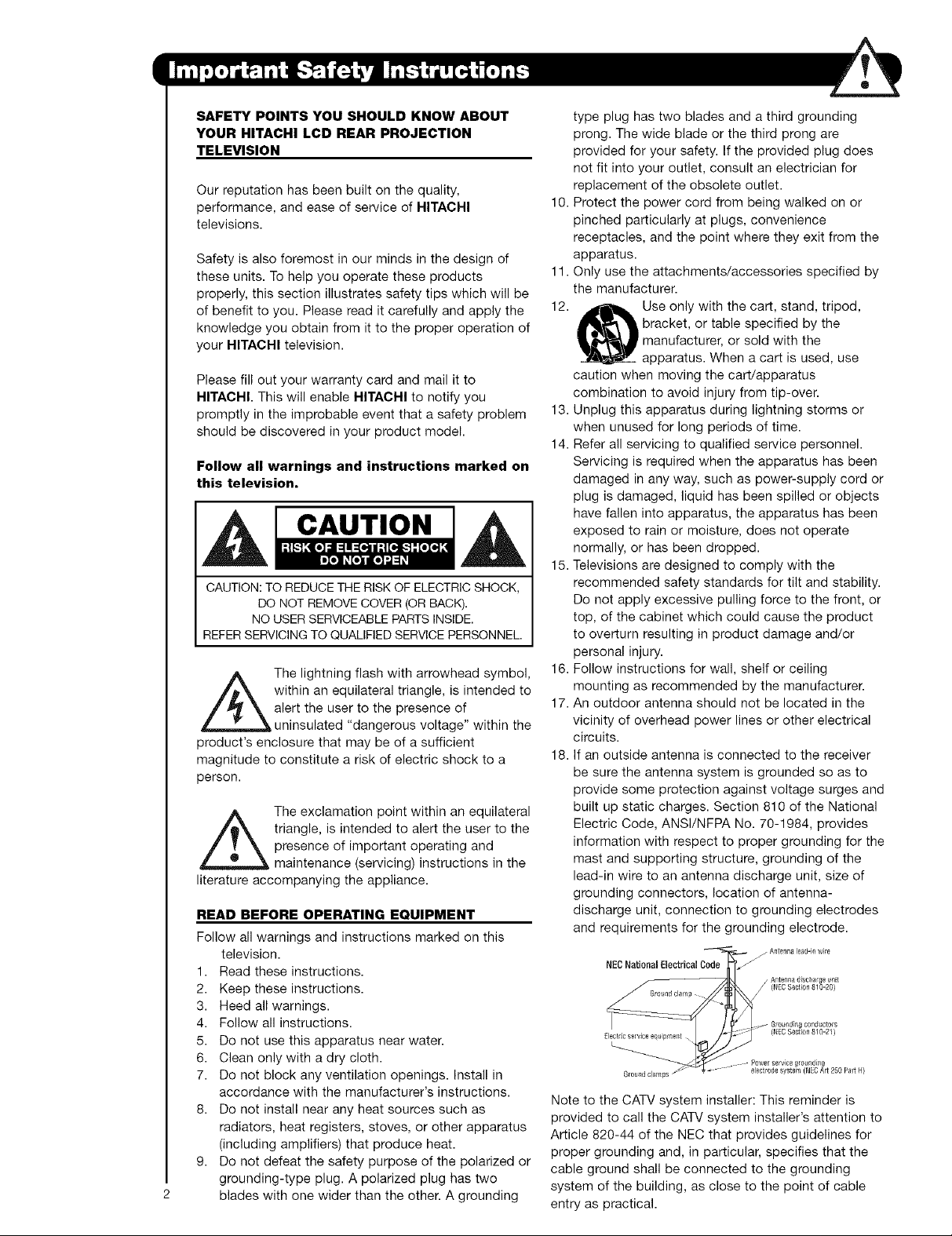
18. If an outside antenna is connected to the receiver
be sure the antenna system is grounded so as to
provide some protection against voltage surges and
built up static charges. Section 810 of the National
Electric Code, ANSl/NFPA No. 70-1984, provides
information with respect to proper grounding for the
mast and supporting structure, grounding of the
lead-in wire to an antenna discharge unit, size of
grounding connectors, location of antenna-
discharge unit, connection to grounding electrodes
and requirements for the grounding electrode.
NEO National Electfi_l O_f _j
Eledricservice equpme_t. ' - '
_ Anterma 'Jischar0e _nit
Grou_,dclamps _ " _ _ " - "
III
Antenna le_d-in Wi_e
(NECSection 810-20}
.,_ Groundbg conductors
(NECSection 810 21_
. - Power service gr0und_no
ode svstelfl N_-CArt 250 Palt H
Note to the CATV system installer: This reminder is
provided to call the CATV system installer's attention to
Article 820-44 of the NEC that provides guidelines for
proper grounding and, in particular, specifies that the
cable ground shall be connected to the grounding
system of the building, as close to the point of cable
entry as practical.
Power source
This television is designed to operate on 120 volts
60 Hz, AC current. Insert the power cord into a 120 volt
60 Hz outlet. The power cord is used as the disconnect
device and shall remain readily operable.
Public viewing of copyrighted material
Public viewing of programs broadcast by TV stations
and cable companies, as well as programs from other
sources, may require prior authorization from the
broadcaster or owner of the video program material.
To prevent electric shock, do not use the television's
(polarized) plug with an extension cord, receptacle, or
other outlet unless the blades and ground terminal can
be fully inserted to prevent blade exposure.
Never connect the television to 50 Hz, direct current, or
anything other than the specified voltage.
Caution
television as this can expose you to very
Never remove the back cover of the
high voltages and other hazards. If the
television does not operate properly,
unplug the television and call your authorized dealer or
service center.
Caution
Adjust only those controls that are covered in the
instructions, as improper changes or modifications not
expressly approved by HITACHI could void the user's
warranty.
Warning
o To reduce the risk of fire or electric shock, do not
expose this apparatus to rain or moisture.
o The television should not be exposed to dripping or
splashing and objects filled with liquids, such as
vases, should not be placed on the television.
Warning
o Do not place any objects on the top of the television
which may fall or cause a child to climb to retrieve the
objects.
This product incorporates copyright protection
technology that is protected by U.S. patents and other
intellectual property rights. Use of this copyright
protection technology must be authorized by
Macrovision Corporation, and is intended for home and
other limited consumer uses only unless otherwise
authorized by Macrovision. Reverse engineering or
disassembly is prohibited.
Note
This digital television is capable of receiving analog
basic, digital basic and digital premium cable television
programming by direct connection to a cable system
providing such programming. A CableCARD provided
by your cable operator is required to view encrypted
digital programming. Certain advanced and interactive
digital cable services such as video-on-demand, a cable
operator's enhanced program guide and data-enhanced
television services may require the use of a set-top box.
For more information call your local cable company.
Note
o There are no user serviceable parts inside the
television.
o Model and serial numbers are indicated on back side
of the television.
Lead/Mercury Notice
f-_ ,
_Hg/,Th_sproduct contains lead and a lamp that contains
mercury. Dispose of this product and its lamp in
accordance with applicable environmental laws. For
lamp recycling and disposal information, go to
www.lamprecycle.org. For product recycling and
disposal information contact your local government
agency or www.eRecycle.org (in California), the
Electronic Industries Alliance at www.eiae.erg (in the
US) or the Electronic Product Stewardship Canada at
www.epsc.ca (in Canada).
FOR MORE INFORMATION, CALL 1-800-HITACHI.
Checktomakesureyouhavethefollowingaccessoriesbeforedisposingofthepackingmaterial.
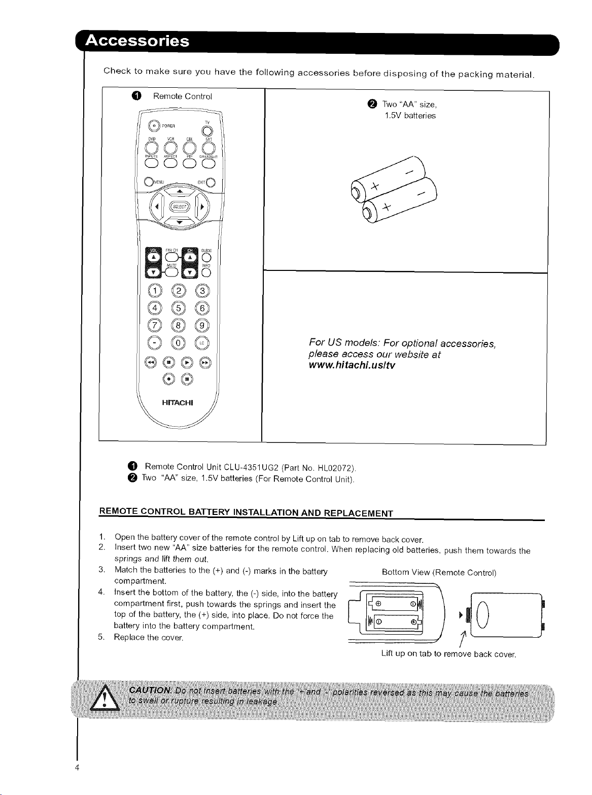
_]P RemoteControl
©00©
O00O
.u0
®@@
®@@
©@@
O@©
®®®®
®®
O Two "AA" size,
1.5V batteries
For US models: For optional accessories,
please access our website at
www.hitachi.usltv
_D Remote Control Unit CLU-4351UG2 (Part No. HL02072).
Two "AA" size, 1.5V batteries (For Remote Control Unit).
REMOTE CONTROL BATTERY INSTALLATION AND REPLACEMENT
1,
Open the battery cover of the remote control by Lift up on tab to remove back cover.
2.
Insert two new "AA" size batteries for the remote control. When replacing old batteries, push them towards the
springs and lift them out.
3.
Match the batteries to the (+) and (-) marks in the battery
compartment.
4.
Insert the bottom of the battery, the (-) side, into the battery / ,.r_,
top of the battery, the (+) side, into place. Do not force the _
compartment first, push towards the springs and insert the L_ h__
battery into the battery compartment.
Replace the cover.
Bottom View (Remote Control)
lrL-_
Lift up on tab to remove back cover
ANTENNA
Unless your LCD Rear PTV is connected to a cable TV system or to a centralized antenna system, a good outdoor
TV antenna is recommended for best performance. However, if you are located in an exceptionally good signal
area that is free from interference and multiple image ghosts, an indoor antenna may be sufficient.
LOCATION
Select an area where sunlight or bright indoor illumination will not fall directly on the picture screen. Also, be sure
that the location selected allows a free flow of air to and from the perforated back cover of the set. To avoid
cabinet warping, cabinet color changes, and increased chance of set failure, do not place the TV where
temperatures can become excessively hot, for example, in direct sunlight or near a heating appliance, etc. When
using your LCD Rear PTV against a wall, keep it at least 10cm (4 inches) from the wall.
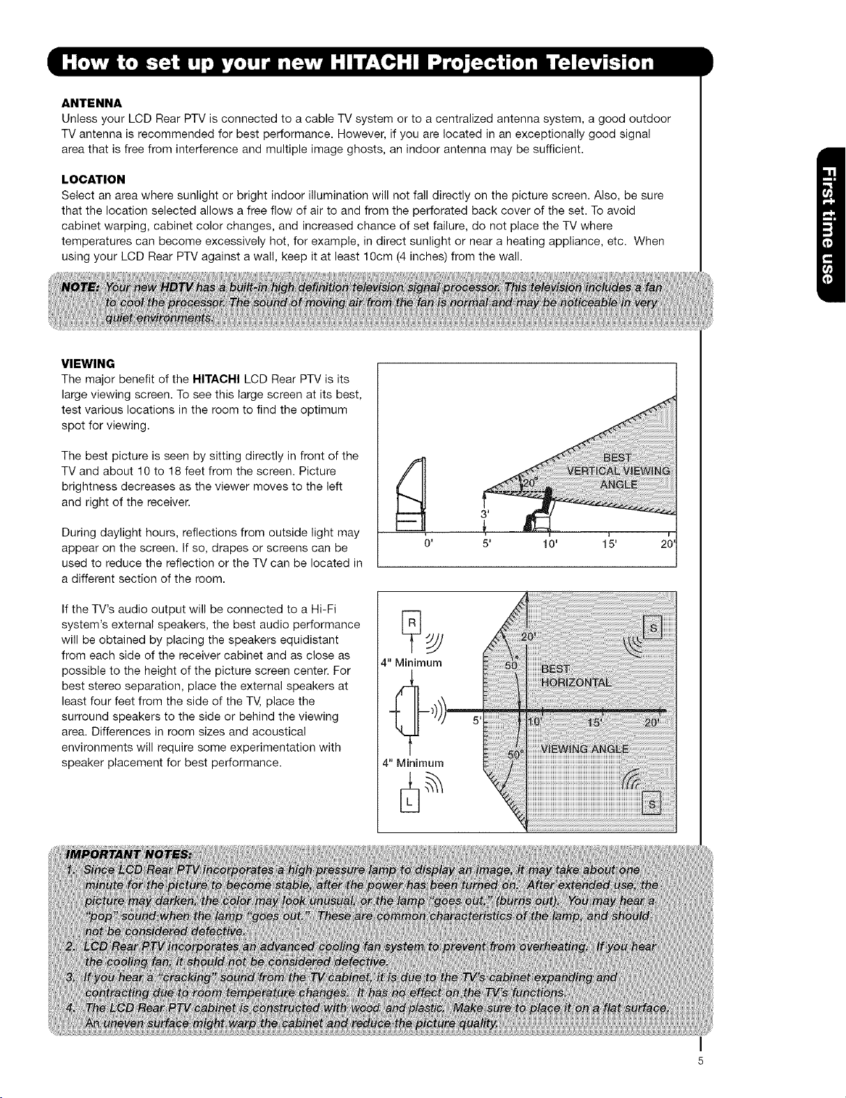
VIEWING
The major benefit of the HITACHI LCD Rear PTV is its
large viewing screen. To see this large screen at its best,
test various locations in the room to find the optimum
spot for viewing.
The best picture is seen by sitting directly in front of the
TV and about 10 to 18 feet from the screen. Picture
brightness decreases as the viewer moves to the left
and right of the receiver.
During daylight hours, reflections from outside light may
appear on the screen. If so, drapes or screens can be
used to reduce the reflection or the TV can be located in
a different section of the room.
If the TV's audio output will be connected to a Hi-Fi
system's external speakers, the best audio performance
will be obtained by placing the speakers equidistant
from each side of the receiver cabinet and as close as
possible to the height of the picture screen center. For
best stereo separation, place the external speakers at
least four feet from the side of the TV, place the
surround speakers to the side or behind the viewing
area. Differences in room sizes and acoustical
environments will require some experimentation with
speaker placement for best performance.
10' 1_5'
4" Minimum
4" Minimum
Mostvideo/audioconnectionsbetweencomponentscanbemadewithshieldedvideoandaudiocablesthathave
phonoconnectors.Forbestperformance,videocablesshoulduse75-Ohmcoaxialshieldedwire.Cablescanbe
purchasedfrommoststoresthatsellaudio/videoproducts.Belowareillustrationsandnamesofcommon
connectors.Beforepurchasinganycables,besureoftheoutputandinputconnectortypesrequiredbythe
variouscomponentsand the length of each cable.
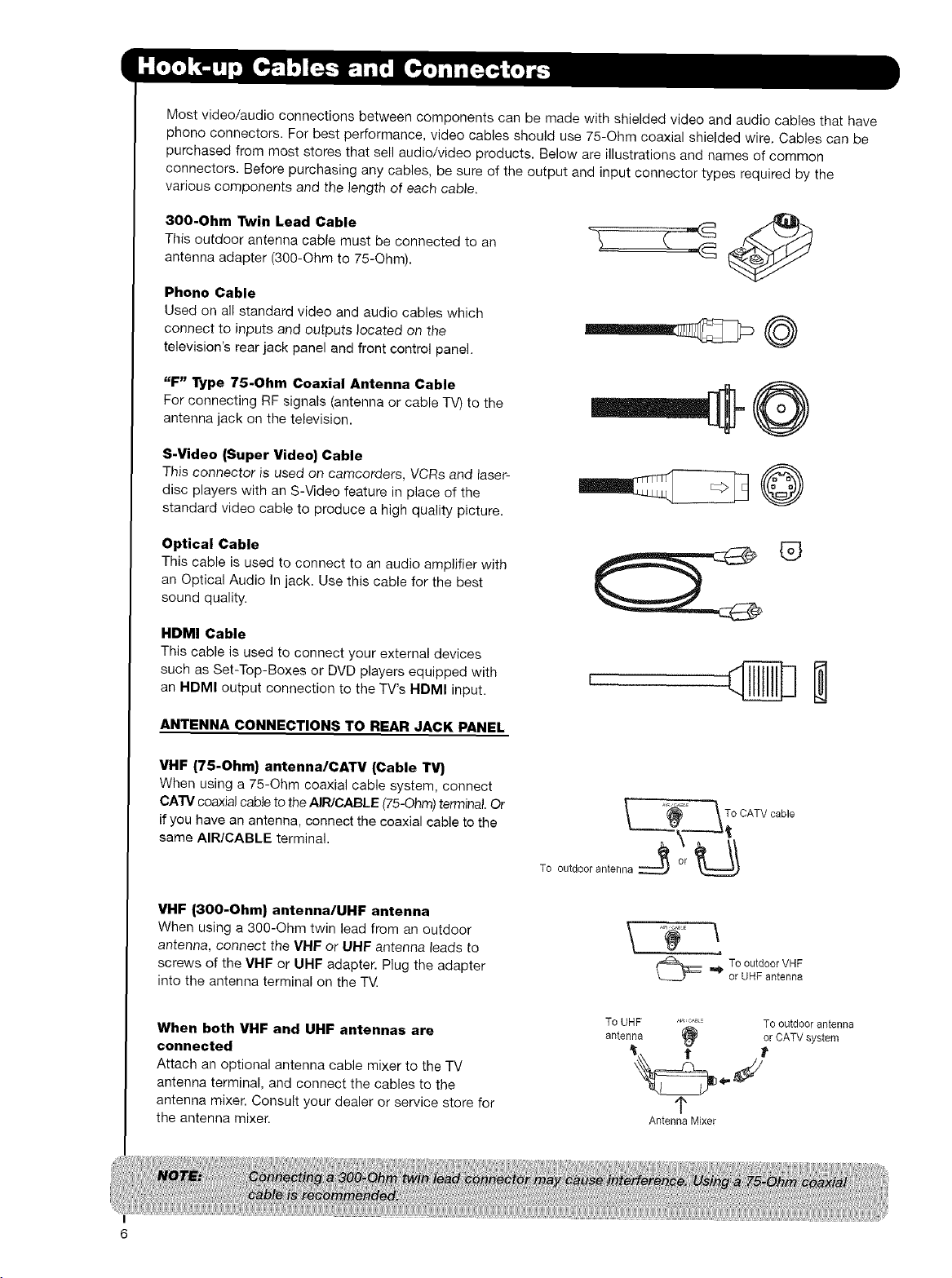
300-Ohm Twin Lead Cable
This outdoor antenna cable must be connected to an
antenna adapter (300-Ohm to 75-Ohm).
Phone Cable
Used on all standard video and audio cables which
connect to inputs and outputs located on the
television's rear jack panel and front control panel.
"F" l_pe 75-Ohm Coaxial Antenna Cable
For connecting RF signals (antenna or cable TV) to the
antenna jack on the television.
S-Video (Super Video) Cable
This connector is used on camcorders, VCRs and laser-
disc players with an S-Video feature in place of the
standard video cable to produce a high quality picture.
Optical Cable
This cable is used to connect to an audio amplifier with
an Optical Audio In jack. Use this cable for the best
sound quality.
HDMI Cable
This cable is used to connect your external devices
such as Set-Top-Boxes or DVD players equipped with
an HDMI output connection to the TV's HDMI input.
ANTENNA CONNECTIONS TO REAR JACK PANEL
VHF (75-Ohm) antenna/CATV (Cable TV)
When using a 75-Ohm coaxial cable system, connect
CA'I'V coaxial cable to the AIR/CABLE (75-Ohm) terminal. Or
if you have an antenna, connect the coaxial cable to the
same AIR/CABLE terminal.
VHF |300-Ohm} antenna/UHF antenna
When using a 300-Ohm twin lead from an outdoor
antenna, connect the VHF or UHF antenna leads to
screws of the VHF or UHF adapter. Plug the adapter
into the antenna terminal on the T_
When both VHF and UHF antennas are
connected
Attach an optional antenna cable mixer to the TV
antenna terminal, and connect the cables to the
antenna mixer. Consult your dealer or service store for
the antenna mixer.
_ _To CATV cable
To outdoorantenna_ er
To UHF ........ To od[doerantenna
antenna
Antenna Mixer
®
To outdoorVHF
or UHF antenna
(_ or CATVsystem
1"
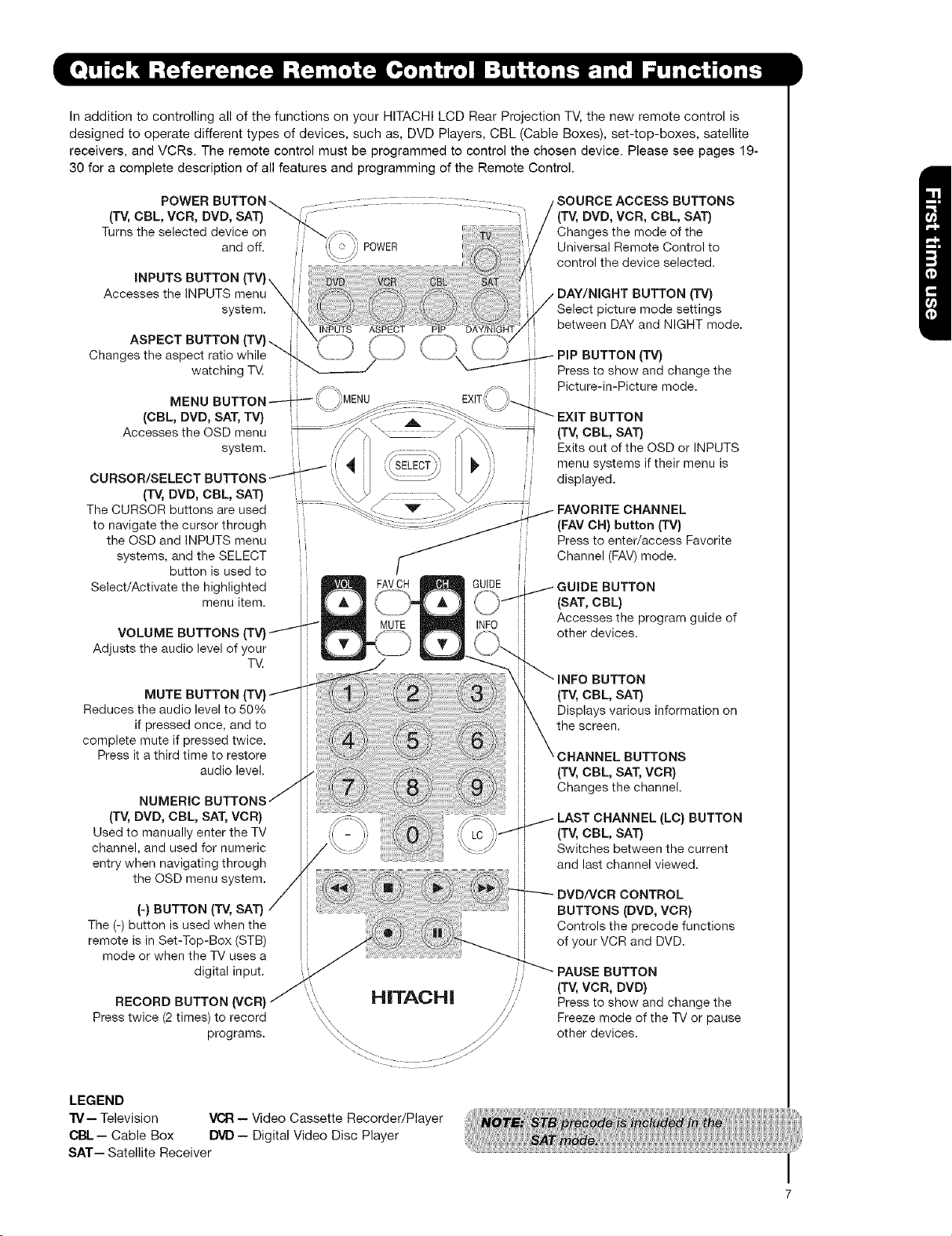
In addition to controlling all of the functions on your HITACHI LCD Rear Projection TV, the new remote control is
designed to operate different types of devices, such as, DVD Players, CBL (Cable Boxes), set-top-boxes, satellite
receivers, and VCRs. The remote control must be programmed to control the chosen device. Please see pages 19-
30 for a complete description of all features and programming of the Remote Control.
(TV, CBL, VCR, DVD, SAT) "-.
Turns the selected device on
Accesses the INPUTS menu \
Changes the aspect ratio while _ ==_/
POWER BUTTON
and off. POWER
INPUTS BUTTON (TV} \
system.
INPUTS ASPECT
ASPECT BUTTON (TV}. /= =_
watching TV.
i
MENU BUTTON
(CBL, DVD, SAT, TV} i
Accesses the OSD menu
system.
CURSOR/SELECT BUTTONS_ I 1
The CURSOR buttons are used
to navigate the cursor through
Select/Activate the highlighted
Adjusts the audio level of your
Reduces the audio level to 50%
complete mute if pressed twice.
(TV, DVD, CBL, SAT}
the OSD and INPUTS menu
systems, and the SELECT i
button is used to
menu item.
VOLUME BUTTONS
TV.
MUTE BUTTON
if pressed once, and to
Press it a third time to restore
audio level.
SOURCE ACCESS BUTTONS
(TV, DVD, VCR, CBL, SAT}
Changes the mode of the
Universal Remote Control to
control the device selected.
DAY/NIGHT BUTTON ('IV}
Select picture mode settings
between DAY and NIGHT mode.
ProPBUTTON (TM)
Press to show and change the
Picture-in-Picture mode.
EXIT BUTTON
(TV, CBL, SAT}
Exits out of the OSD or INPUTS
menu systems if their menu is
displayed.
FAVORITE CHANNEL
(FAV CH} button (TV}
Press to enter/access Favorite
Channel (FAV) mode.
GUIDE BUTTON
(SAT, CBL}
Accesses the program guide of
other devices.
INFO BUTTON
(TV, CBL, SAT}
Displays various information on
the screen.
CHANNEL BUTTONS
(TV, CBL, SAT, VCR}
Changes the channel.
(TV, DVD, CBL, SAT, VCR}
Used to manually enter the TV
channel, and used for numeric
entry when navigating through
the OSD menu system.
(-} BUTTON (TV, SAT}
The (-) button is used when the
remote is in Set-Top-Box (STB)
mode or when the "iV uses a
digital input.
RECORD BUTTON (VCR}
Press twice (2 times) to record
programs.
LEGEND
"IV-- Television VCR -- Video Cassette Recorder/Player
CBL- Cable Box DVD- Digital Video Disc Player
SAT-- Satellite Receiver
' Freeze mode of the "iV or pause
"'_i_ H|TAOH| ,......
LAST CHANNEL (LC} BUTTON
(TV, CBL, SAT)
Switches between the current
and last channel viewed.
DVD/VCR CONTROL
BUTTONS (DVD, VCR)
Controls the precode functions
of your VCR and DVD.
PAUSE BUTTON
/ .... (TV, VCR, DVD}
to
Press show and the
other devices.
change
I
7
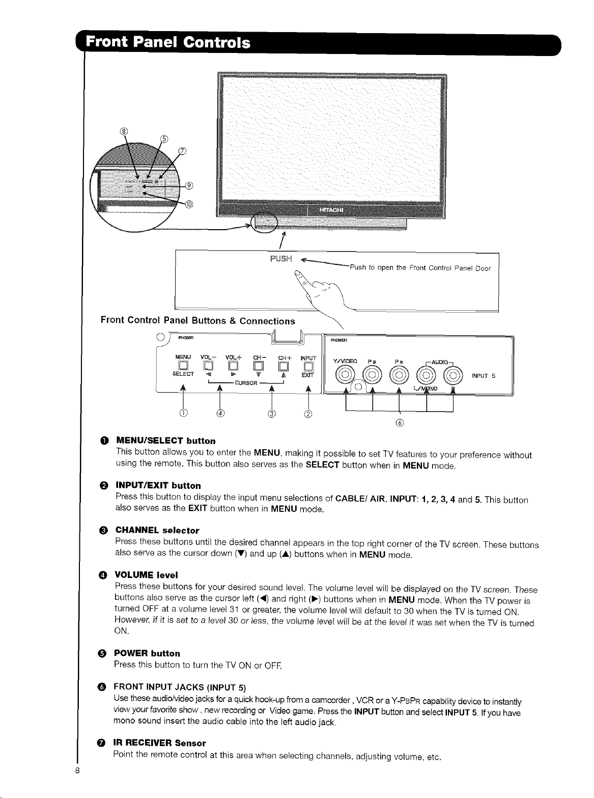
Front Control Panel Buttons & Connections
_P_sh to open the Front Control Panel D
,5= O TILY,v.oooo. oR oo,o.
INPUT 5
®
O MENU/SELECT button
This button allows you to enter the MENU, making it possible to set TV features to your preference without
using the remote. This button also serves as the SELECT button when in MENU mode.
O INPUT/EXIT button
Press this button to display the input menu selections of CABLE/AIR, INPUT: 1, 2, 3, 4 and 5. This button
also serves as the EXIT button when in MENU mode.
O CHANNEL selector
Press these buttons until the desired channel appears in the top right corner of the TV screen. These buttons
also serve as the cursor down (V) and up (A) buttons when in MENU mode.
VOLUME level
O
Press these buttons for your desired sound level. The volume level will be displayed on the TV screen. These
buttons also serve as the cursor left (_i) and right (1_) buttons when in MENU mode. When the TV power is
turned OFF at a volume level 31 or greater, the volume level will default to 30 when the TV is turned ON.
However, if it is set to a level 30 or less, the volume level will be at the level it was set when the TV is turned
ON.
O POWER button
Press this button to turn the TV ON or OFF.
O FRONT INPUT JACKS (INPUT 5)
Use these audio/Video jacks for a quick hook-up from a camcorder, VCR or a Y-PBPR capability device to instantly
view your favorite show, new recording or Video game. Press the INPUT button and select INPUT 5. If you have
mono sound insert the audio cable into the left audio jack.
O IR RECEIVER Sensor
Point the remote control at this area when selecting channels, adjusting volume, etc.
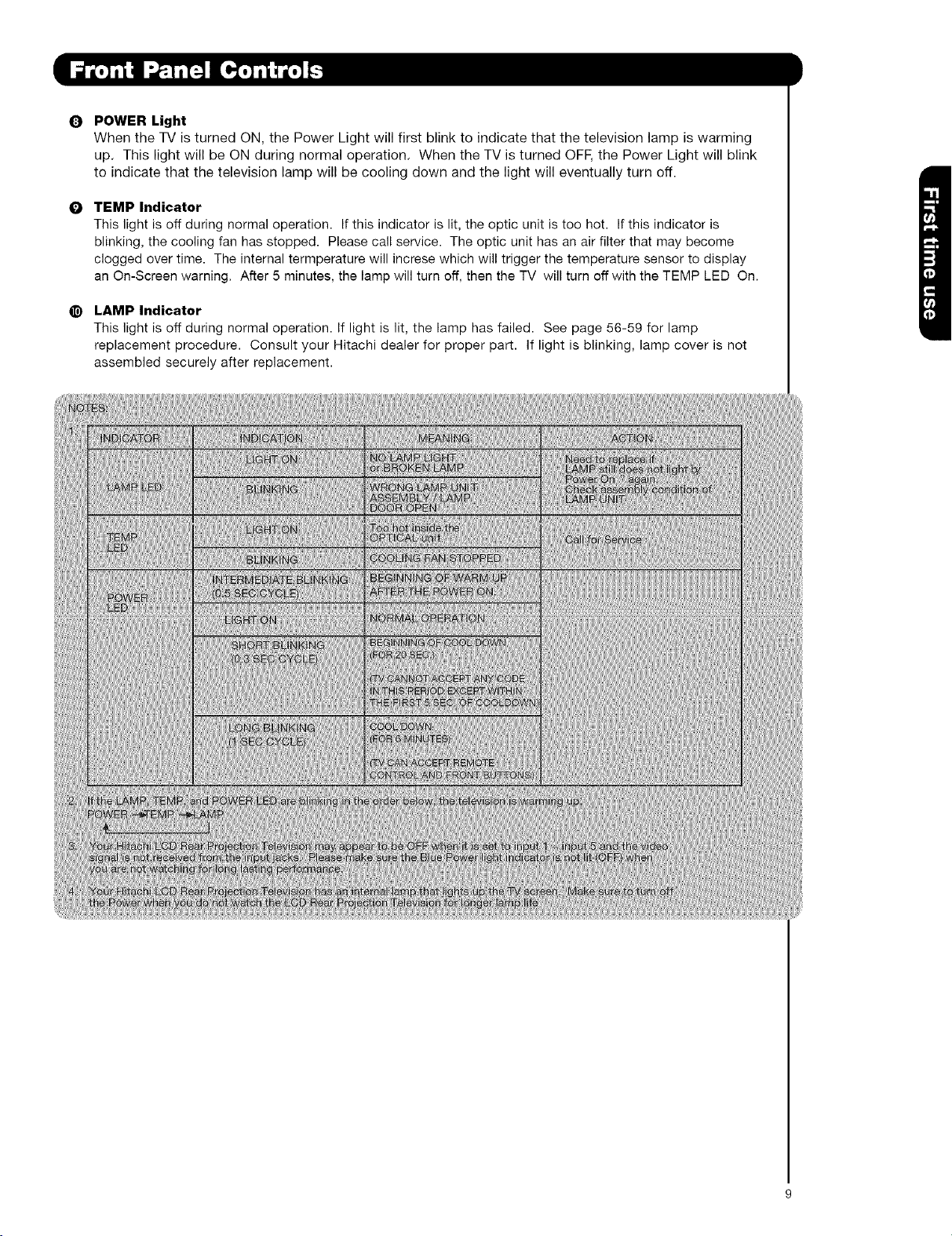
Q POWER Light
When the TV is turned ON, the Power Light will first blink to indicate that the television lamp is warming
up. This light will be ON during normal operation. When the TV is turned OFF, the Power Light will blink
to indicate that the television lamp will be cooling down and the light will eventually turn off.
TEMP Indicator
O
This light is off during normal operation. If this indicator is lit, the optic unit is too hot. If this indicator is
blinking, the cooling fan has stopped. Please call service. The optic unit has an air filter that may become
clogged over time. The internal termperature will increse which will trigger the temperature sensor to display
an On-Screen warning. After 5 minutes, the lamp will turn off, then the TV will turn off with the TEMP LED On.
LAMP Indicator
@
This light is off during normal operation. If light is lit, the lamp has failed. See page 56-59 for lamp
replacement procedure. Consult your Hitachi dealer for proper part. If light is blinking, lamp cover is not
assembled securely after replacement.
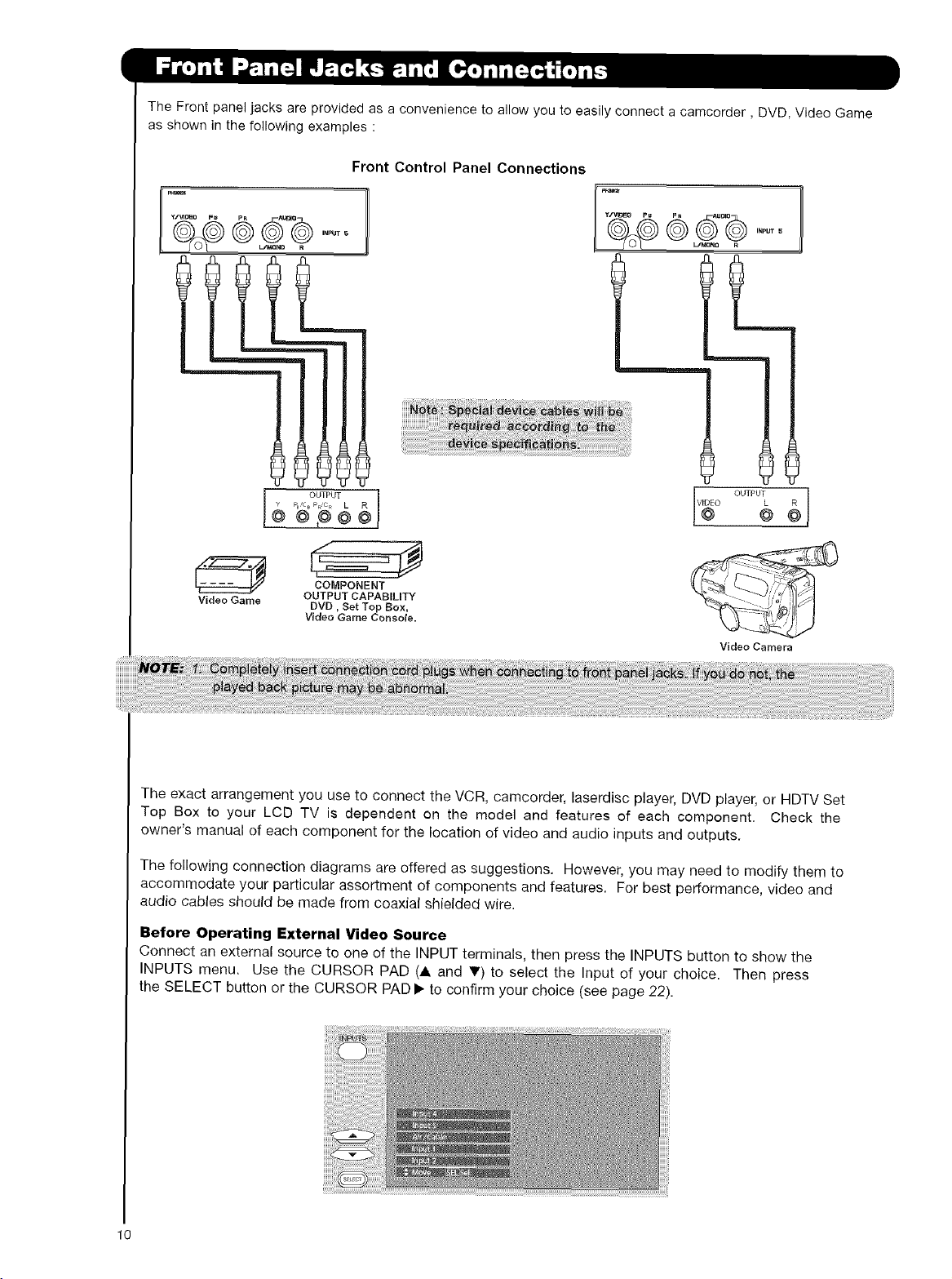
TheFrontpaneljacksareprovidedasaconveniencetoallowyoutoeasilyconnectacamcorder,DVD,VideoGame
asshowninthefollowingexamples:
Front Control Panel Connections
D
INPUT S
OOTPOTPB'CBPRC_ L
©,@@
L/_ R
COMPONENT
Video Game DVD, Set Top Box,
OUTPUT CAPABILITY
Video Game Console.
Video Camera
The exact arrangement you use to connect the VCR, camcorder, laserdisc player, DVD player, or HDTV Set
Top Box to your LCD TV is dependent on the model and features of each component. Check the
owner's manual of each component for the location of video and audio inputs and outputs.
The following connection diagrams are offered as suggestions. However, you may need to modify them to
accommodate your particular assortment of components and features. For best performance, video and
audio cables should be made from coaxial shielded wire.
Before Operating External Video Source
Connect an external source to one of the INPUT terminals, then press the INPUTS button to show the
INPUTS menu, Use the CURSOR PAD (A and V) to select the Input of your choice. Then press
the SELECT button or the CURSOR PAD I_ to confirm your choice (see page 22).
10
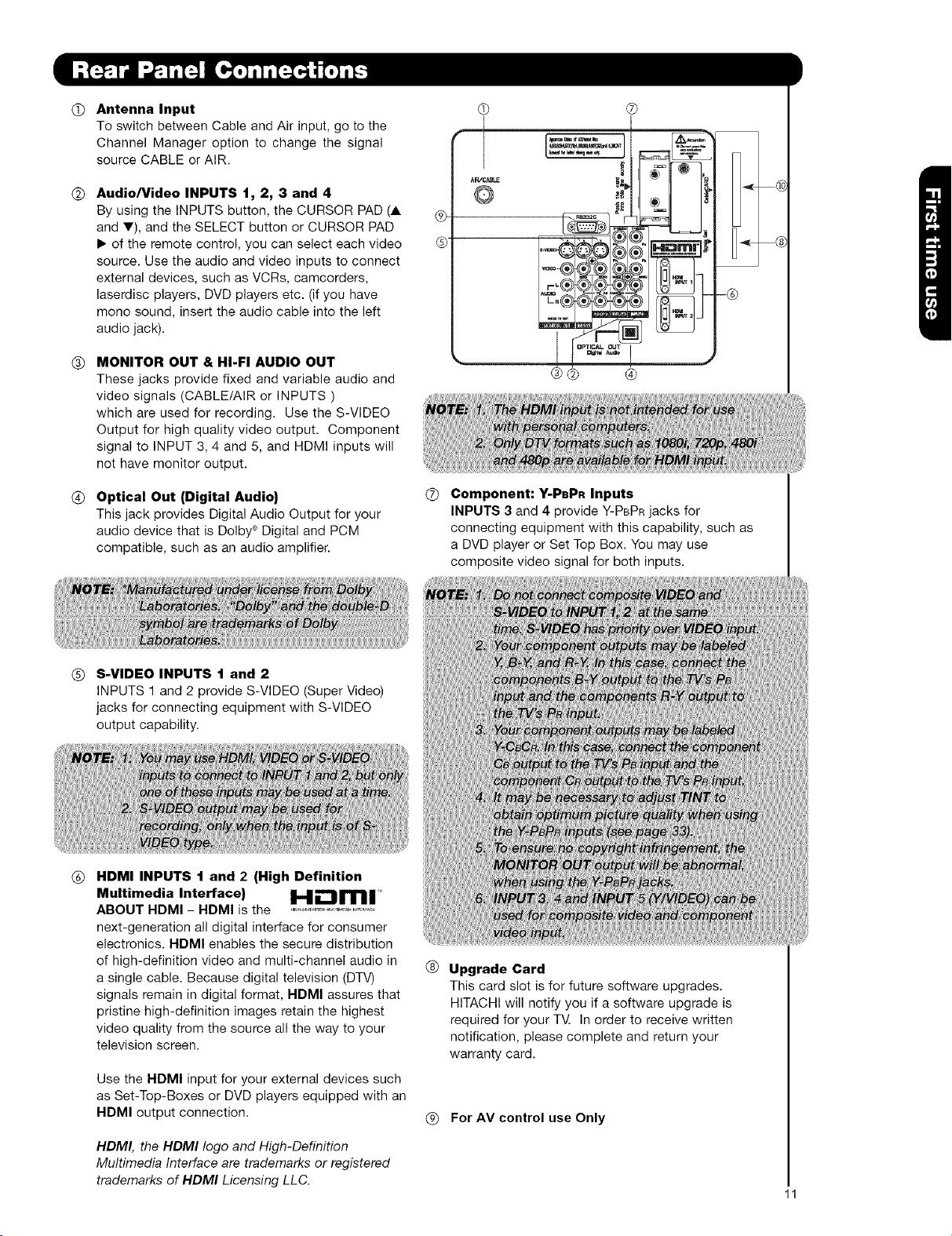
(_)Antenna Input
To switch between Cable and Air input, go to the
Channel Manager option to change the signal
source CABLE or AIR.
(_) Audio/Video INPUTS 1, 2, 3 and 4
By using the INPUTS button, the CURSOR PAD (A
and T), and the SELECT button or CURSOR PAD
• of the remote control, you can select each video
source. Use the audio and video inputs to connect
external devices, such as VCRs, camcorders,
laserdisc players, DVD players etc. (if you have
mono sound, insert the audio cable into the left
audio jack).
(_T) MONITOR OUT & HI-FI AUDIO OUT
These jacks provide fixed and variable audio and
video signals (CABLE/AIR or INPUTS )
which are used for recording. Use the S-VIDEO
Output for high quality video output. Component
signal to INPUT 3, 4 and 5, and HDMI inputs will
not have monitor output.
®
¢
-®
(_ Optical Out (Digital Audio)
This jack provides Digital Audio Output for your
audio device that is Dolby ® Digital and PCM
compatible, such as an audio amplifier.
(_) S-VIDEO INPUTS 1 and 2
INPUTS 1 and 2 provide S-VIDEO (Super Video)
jacks for connecting equipment with S-VIDEO
output capability.
(_) HDMI INPUTS 1 and 2 (High Definition
Multimedia Interface)
ABOUT HDMI - HDMI is the ....................,...............
next-generation all digital interface for consumer
electronics. HDMI enables the secure distribution
of high-definition video and multi-channel audio in
a single cable. Because digital television (DTV)
signals remain in digital format, NDMI assures that
pristine high-definition images retain the highest
video quality from the source all the way to your
television screen.
Use the HDMI input for your external devices such
as Set-Top-Boxes or DVD players equipped with an
HDMI output connection.
0 Component: Y-PBPR Inputs
INPUTS 3 and 4 provide Y-PBPR jacks for
connecting equipment with this capability, such as
a DVD player or Set Top Box. You may use
composite video signal for both inputs.
(_) Upgrade Card
This card slot is for future software upgrades.
HITACHI will notify you if a software upgrade is
required for your T_ In order to receive written
notification, please complete and return your
warranty card.
For AV control use Only
HDMI, the HDMI logo and High-Definition
Multimedia Interface are trademarks or registered
trademarks of HDMI Licensing LL C.
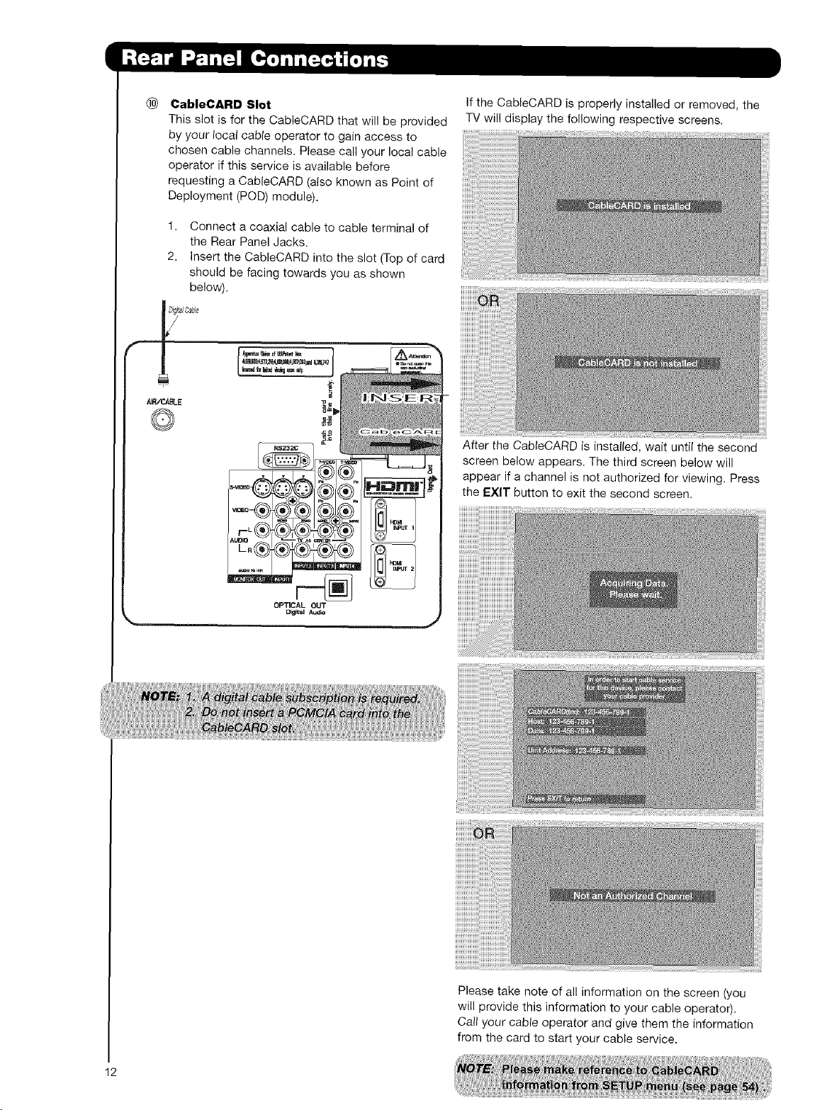
® CableCARD Slot
This slot is for the CableCARD that will be provided
by your local cable operator to gain access to
chosen cable channels. Please call your local cable
operator if this service is available before
requesting a CableCARD (also known as Point of
Deployment (POD) module).
1. Connect a coaxial cable to cable terminal of
the Rear Panel Jacks.
2. Insert the CableCARD into the slot (Top of card
should be facing towards you as shown
below).
AN_AN_E
®
If the CableCARD is properly installed or removed, the
TV will display the following respective screens.
After the CabteCARD is instatied, wait until the second
screen below appears. The third screen below will
appear if a channel is not authorized for viewing. Press
the EXIT button to exit the second screen.
Please take note of all information on the screen (you
will provide this information to your cable operator).
Call your cable operator and give them the information
from the card to start your cable service.
12
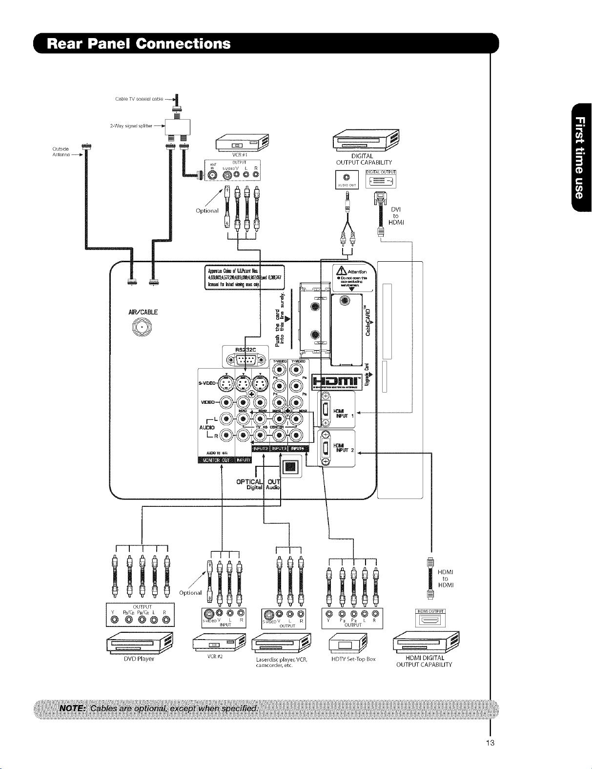
Cable TV coaxial cable
Otltside
AIR/CABLE
©
DIGITAL
OUTPUT CAPABILITY
q DVl
HDMI
_ ,o
L__
I
i i i i i
OUTPUT
DVD Player
OPTICAL
Oioital
r
to
HDMI
HDMI
,==_ _
HDMI DIGITAL
OUTPUT CAPABILITY
I
13
S-VIDEO,Y-PBPR,orHDMIconnectionsareprovidedforhighperformancelaserdiscplayers,VCRsetc.that
havethisfeature.Usetheseconnectionsinplaceoftilestandardvideoconnectionifyourdevicehasthis
feature.
Ifyourdevicehasonlyoneaudiooutput(monosound),connectittotheleftaudiojackon(L/(MONO))the
RearPanel
Refertotheoperatingguideofyourotherelectronicequipmentforadditionalinformationonconnecting
yourhook-upcables.
AsingleVCRcanbeusedforVCR#1andVCR#2,butnotethataVCRcannotrecorditsown video or line
output (INPUT: 1 in the example on page 14). Refer to your VCR operating guide for more information on
line input-output connections.
Connect only 1 component NCR, DVD player, camcorder, etc.) to each input jack.
COMPONENT: Y-PBPR (Input 3, 4 & 5) connections are provided for high performance components, such as
DVD players and set-top-boxes. Use these connections in place of the standard video connection if your
device has this feature.
Your component outputs may be labeled Y, B-Y, and R-Y. In this case, connect the components B-Y
output to the TV's PB input and the components R-Y output to the TV's PR input.
Your component outputs may be labeled Y-CBC R. In this case, connect the components C B output to the
TV's PB input and the components CR output to the TV's PR input.
It may be necessary to adjust TINT to obtain optimum picture quality when using the Y-PBPR inputs. (See
page 33)
• To ensure no copyright infringement, the MONITOR OUT output will be abnormal, when using the Y-PBPR , and
HDMI input jacks.
• Input 1 or 2 can accept HDMI signal.
• S-VIDEO monitor output may be used for recording only when the input is of S-VIDEO type.
• When using a HDMI input from a Set-Top-Box, it is recommended to use a 1080i or 720p input signal.
14
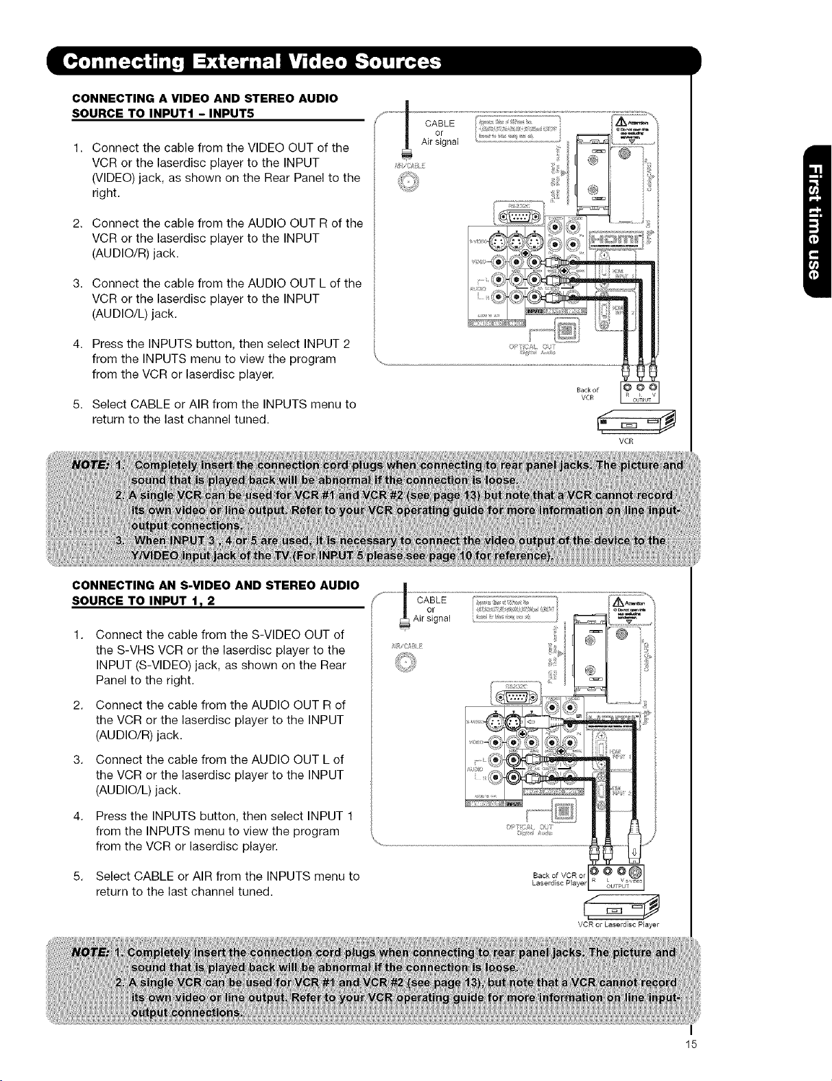
CONNECTING A VIDEO AND STEREO AUDIO
SOURCE TO INPUT1 - INPUT5
Connect the cable from the VIDEO OUT of the
VCR or the laserdisc player to the INPUT
(VIDEO) jack, as shown on the Rear Panel to the
right.
Connect the cable from the AUDIO OUT R of the
VCR or the laserdisc player to the INPUT
(AUDIO/R) jack.
Connect the cable from the AUDIO OUT L of the
VCR or the laserdisc player to the INPUT
(AUDIO/L) jack.
Press the INPUTS button, then select INPUT 2
from the INPUTS menu to view the program
from the VCR or laserdisc player.
Select CABLE or AIR from the INPUTS menu to
return to the last channel tuned.
CABLE
or
Air signal
VCR
CONNECTING AN S-VIDEO AND STEREO AUDIO
SOURCE TO INPUT 1T 2
1.
Connect the cable from the S-VIDEO OUT of
the S-VHS VCR or the laserdisc player to the
INPUT (S-VIDEO) jack, as shown on the Rear
Panel to the right.
2.
Connect the cable from the AUDIO OUT R of
the VCR or the laserdisc player to the INPUT
(AUDIO/R) jack.
3.
Connect the cable from the AUDIO OUT L of
the VCR or the laserdisc player to the INPUT
(AUDIO/L) jack.
4.
Press the INPUTS button, then select INPUT 1
from the INPUTS menu to view the program
from the VCR or laserdisc player.
5. Select CABLE or AIR from the INPUTS menu to
return to the last channel tuned.
VCR or Laserdisc Player
15

CONNECTING A COMPONENT SOURCE WITH
HDMI OR DVI CAPABILITY TO INPUT 1 OR 2
Connect the HDMI or DVI to HDMI connection
cable from the output of the HDTV set top box
or DVD player to the HDMI
input as shown on the Rear panel below.
With DVl output, connect the cable from the
AUDIO OUT R of the HDTV set top box or DVD
player to the INPUT (AUDIO/R) jack as shown on
the Rear Panel below.
3,
With DVl output, connect the cable from the
AUDIO OUT L of the HDTV set top box or DVD
player to the INPUT (AUDIO/L) jack as shown
on the Rear Panel below,
4,
Press the INPUTS button, then select INPUTS 1,
or 2 to view the program from the HDTV set
top box or DVD player.
Select CABLE or AIR from the INPUTS menu to
return to the last channel viewed.
HDMI input
Cable
iHDM _
©k,
HDTV Set Tol) Box or
DVD Payer
DVI to HDMI !Bj_ut
--;q 1
B ckofHDTV Set Top Box or
HDT//Set Top Box or
DS/D P_sy÷_
16
DVD Player
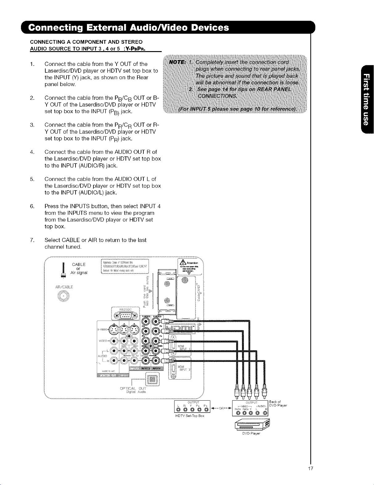
CONNECTINGA COMPONENT AND STEREO
AUDIO SOURCE TO INPUT 3 _4 or 5 :Y-PePR.
Connect the cable from the Y OUT of the
Laserdisc/DVD player or HDTV set top box to
the INPUT (Y)jack, as shown on the Rear
panel below.
Connect the cable from the PB/CB OUT or B-
Y OUT of the Laserdisc/DVD player or HDTV
set top box to the INPUT (PB) jack.
Connect the cable from the PR/CR OUT or R-
Y OUT of the Laserdisc/DVD player or HDTV
set top box to the INPUT (PR) jack.
Connect the cable from the AUDIO OUT R of
the Laserdisc/DVD player or HDTV set top box
to the INPUT (AUDIO/R) jack.
5. Connect the cable from the AUDIO OUT L of
the Laserdisc/DVD player or HDTV set top box
to the INPUT (AUDIO/L) jack.
Press the INPUTS button, then select INPUT 4
from the INPUTS menu to view the program
from the Laserdisc/DVD player or HDTV set
top box.
Select CABLE or AIR to return to the last
channel tuned.
oF
Air signal
CABLE
Back of
DVD Player
DVD Player
17
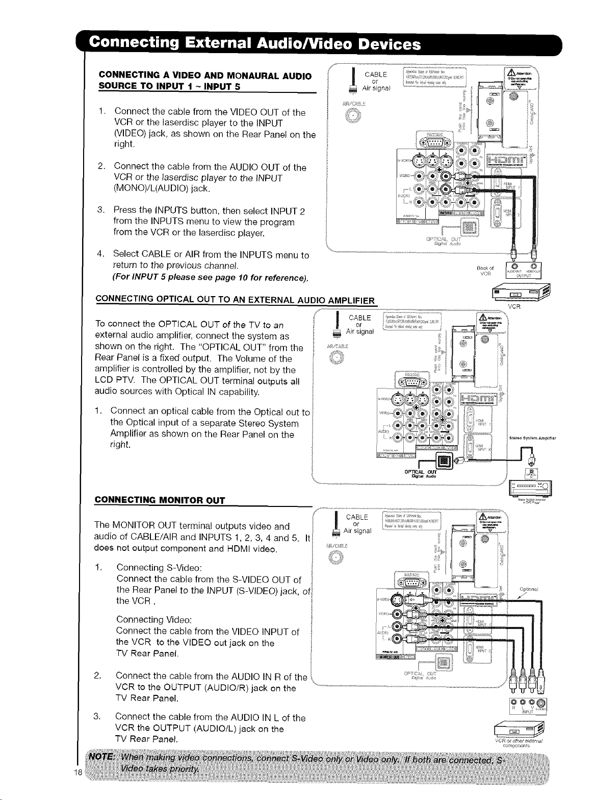
CONNECTING A VIDEO AND MONAURAL AUDIO
SOURCE TO INPUT 1 ~ INPUT 5
Connect the cable from the VIDEO OUT of the
VCR or the laserdisc player to the INPUT
(VIDEO) jack, as shown on the Rear Panel on the
right.
Connect the cable from the AUDIO OUT of the
VCR or the laserdisc player to the INPUT
(MONO)/L(AUDIO) jack
3,
Press the INPUTS button, then select INPUT 2
from the INPUTS menu to view the program
from the VCR or the laserdisc player.
Select CABLE or AIR from the INPUTS menu to
return to the previous channel.
(For INPUT 5 please see page 10 for reference).
or
CABLE
Air signal
CONNECTING OPTICAL OUT TO AN EXTERNAL AUDIO AMPLIFIER
f
To connect the OPTICAL OUT of the TV to an
external audio amplifier, connect the system as
CABLE
or
Airsignal
shown on the right, The "OPTICAL OUT" from the
Rear Panel is a fixed output The Volume of the
amplifier is controlled by the amplifier, not by the
LCD PTV The OPTICAL OUT terminal outputs all
audio sources with Optical IN capability.
1.
Connect an optical cable from the Optical out to
the Optical input of a separate Stereo System
Amplifier as shown on the Rear Panel on the
right.
CONNECTING MONITOR OUT
The MONITOR OUT terminal outputs video and Airsignal
or
audio of CABLE/AIR and INPUTS 1,2, 3, 4 and 5. It
does not output component and HDMI video. _'_"
1,
Connecting S-Video:
Connect the cable from the S-VIDEO OUT of
the Rear Panel to the INPUT (S-VIDEO) jack, of
the VCR
VCR
Optional
18 ¸
Connecting Video:
Connect the cable from the VIDEO INPUT of
the VCR to the VIDEO out jack on the
TV Rear Panel.
2.
Connect the cable from the AUDIO IN R of the
VCR to the OUTPUT (AUDIOIR) jack on the
TV Rear Panel.
3,
Connect the cable from the AUDIO IN L of the
VCR the OUTPUT (AUDIO/L) jack on the
TV Rear Panel
VCR or other extert_at
components
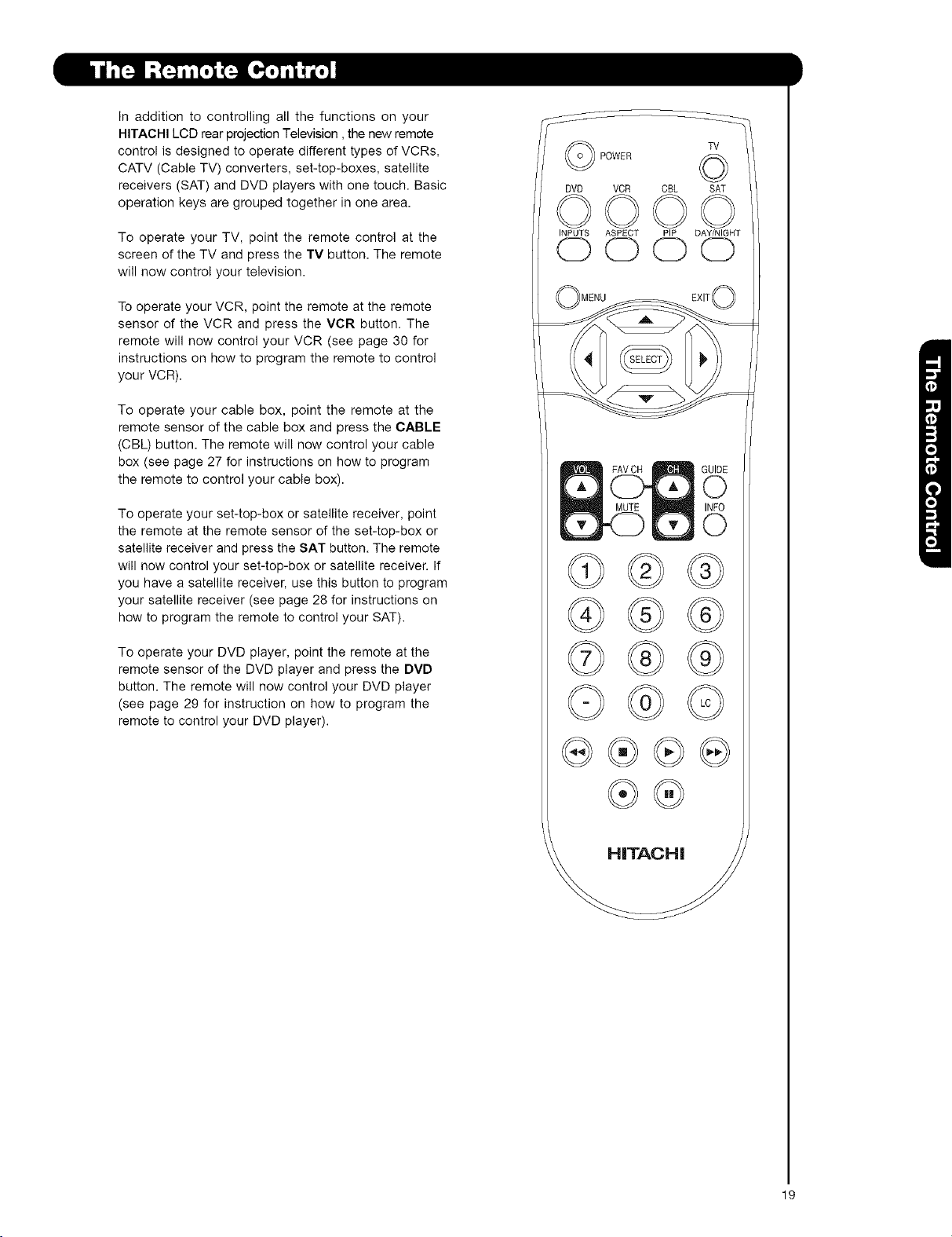
Inadditiontocontrollingallthefunctionsonyour
HITACHILCDrearprojectionTelevision,thenewremote
controlisdesignedtooperatedifferenttypesofVCRs,
CATV(CableTV)converters,set-top-boxes,satellite
receivers(SAT)andDVDplayerswithonetouch.Basic
operationkeysaregroupedtogetherinonearea.
POWER O
DVD
VCR CBL SAT
TV
TooperateyourTV,pointtheremotecontrolatthe
screenoftheTVandpresstheTVbutton.Theremote
willnowcontrolyourtelevision.
TooperateyourVCR,pointtheremoteattheremote
sensoroftheVCRandpresstheVCRbutton.The
remotewillnowcontrolyourVCR(seepage30for
instructionsonhowtoprogramtheremotetocontrol
yourVCR).
Tooperateyourcablebox,pointtheremoteatthe
remotesensorofthecableboxandpresstheCABLE
(CBL)button.Theremotewillnowcontrolyourcable
box(seepage27forinstructionsonhowtoprogram
theremotetocontrolyourcablebox).
Tooperateyourset-top-boxorsatellitereceiver,point
theremoteattheremotesensoroftheset-top-boxor
satellitereceiverandpresstheSATbutton.Theremote
willnowcontrolyourset-top-boxorsatellitereceiver.If
youhaveasatellitereceiver,usethisbuttontoprogram
yoursatellitereceiver(seepage28forinstructionson
howtoprogramtheremotetocontrolyourSAT).
TooperateyourDVDplayer,pointtheremoteatthe
remotesensoroftheDVDplayerandpresstheDVD
button.TheremotewillnowcontrolyourDVDplayer
(seepage29forinstructiononhowtoprogramthe
remotetocontrolyourDVDplayer).
INPUTS ASPECT PIP DAY/NIGHT
Cb C) C) C)
©
®®
HITACHI
19
0-
......
@-
INPUTS ASPECT PIP
-0
--0
@
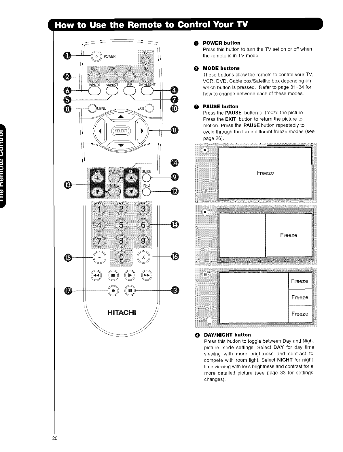
POWER button
0
Press this button to turn the TV set on or off when
the remote is in TV mode.
MODE buttons
0
These buttons allow the remote to control your TV,
VCR, DVD, Cable box/Satellite box depending on
which button is pressed. Refer to page 31 ~34 for
how to change between each of these modes.
PAUSE button
0
Press the PAUSE button to freeze the picture.
Press the EXIT button to return the picture to
motion. Press the PAUSE button repeatedly to
cycle through the three different freeze modes (see
page 26).
Freeze
O DAY/NIGHT button
Press this button to toggle between Day and Night
picture mode settings. Select DAY for day time
viewing with more brightness and contrast to
compete with room light. Select NIGHT for night
time viewing with less brightness and contrast for a
more detailed picture (see page 33 for settings
changes).
20
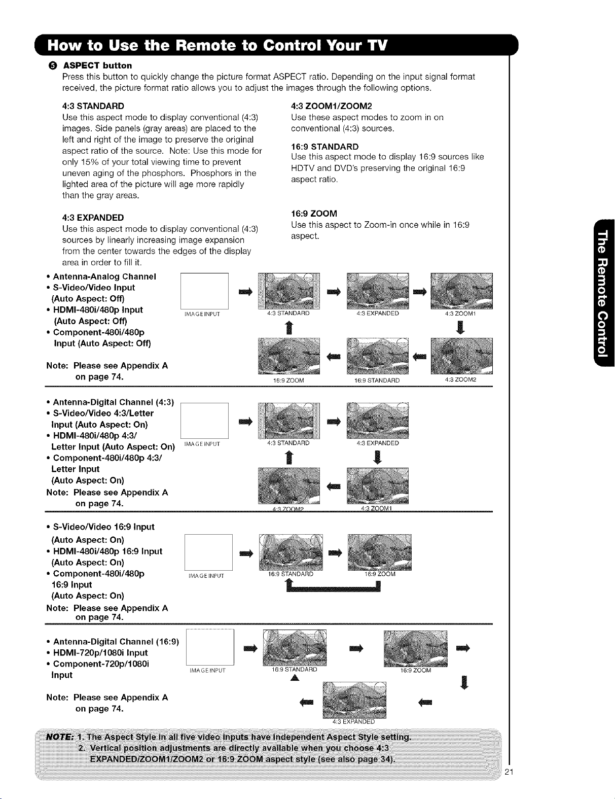
O ASPECT button
Press this button to quickly change the picture format ASPECT ratio. Depending on the input signal format
received, the picture format ratio allows you to adjust the images through the following options.
4:3 STANDARD
Use this aspect mode to display conventional (4:3)
images. Side panels (gray areas) are placed to the
left and right of the image to preserve the original
aspect ratio of the source. Note: Use this mode for
only 15% of your total viewing time to prevent
uneven aging of the phosphors. Phosphors in the
lighted area of the picture will age more rapidly
than the gray areas.
4:3 EXPANDED
Use this aspect mode to display conventional (4:3)
sources by linearly increasing image expansion
from the center towards the edges of the display
area in order to fill it.
• Antenna-Analog Channel
• S-Video/video Input
(Auto Aspect: Off)
• HDMI-480i/48Op Input IMAGEINPUT
(Auto Aspect: Off)
• Component-480i/480p
Input (Auto Aspect: Off)
4:3 ZOOMI/ZOOM2
Use these aspect modes to zoom in on
conventional (4:3) sources.
16:9 STANDARD
Use this aspect mode to display 16:9 sources like
HDTV and DVD's preserving the original 16:9
aspect ratio.
16:9 ZOOM
Use this aspect to Zoom-in once while in 16:9
aspect.
4:3 STANDARD
4:3 EXPANDED
l
4:3 ZOOM1
!
Note: Please see Appendix A
on page 74.
16:9 ZOOM
• Antenna-Digital Channel (4:3)
• S-Video/Video 4:3/Letter
Input (Auto Aspect: On)
• HDMI-480i/48Op 4:3/
Letter Input (Auto Aspect: On) 4:3STANDARD
IMAGE INPUT
=O
• Component-480i/480p 4:3/ "_
Letter Input
(Auto Aspect: On)
Note: Please see Appendix A
on page 74.
• S-Video/Video 16:9 Input
(Auto Aspect: On)
• HDMI-480i/48Op 16:9 Input
(Auto Aspect: On)
• Component-480i/480p
IMA G EINPUT
16:9 STANDARD 16:9 ZOOM
16:9 Input
(Auto Aspect: On)
Note: Please see Appendix A
on page 74.
• Antenna-Digital Channel (16:9)
• HDMI-72Op/1080i Input
• Component-720p/1080i
Input
Note: Please see Appendix A
on page 74.
IMAGE INPUT
gin,
16:9 STANDARD
A
_g
,I
4:3 EXPANDED
16:9 STANDARD
4:3 EXPANDED
!
4:3ZOOM1
4:3 ZOOM2
16:9 ZOOM
!
21
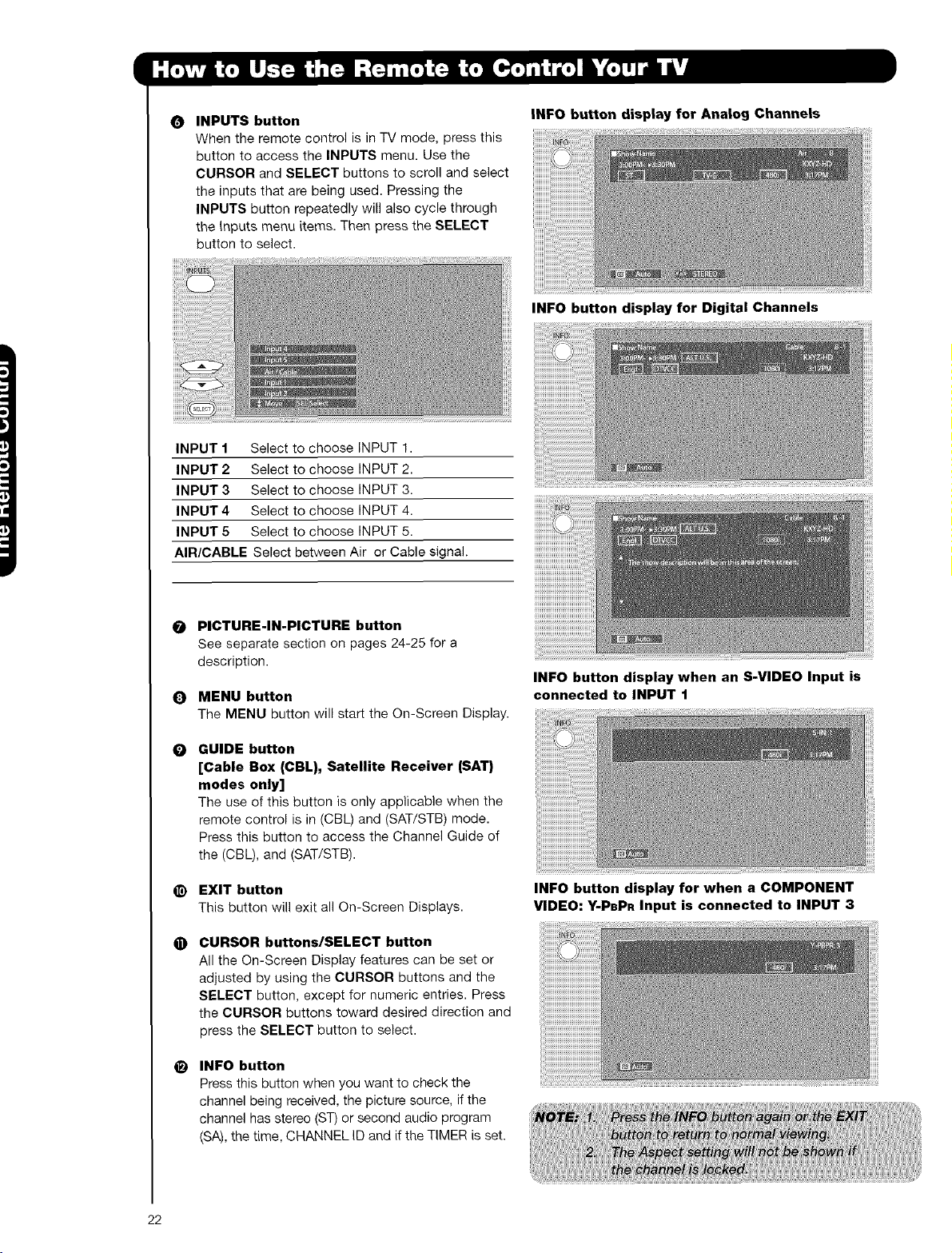
INPUTS button
0
When the remote control is in TV mode, press this
button to access the INPUTS menu. Use the
CURSOR and SELECT buttons to scroll and select
the inputs that are being used. Pressing the
INPUTS button repeatedly will also cycle through
the inputs menu items. Then press the SELECT
button to select.
INPUT 1 Select to choose INPUT 1.
INPUT 2 Select to choose INPUT 2.
INPUT 3 Select to choose INPUT 3.
INPUT 4 Select to choose INPUT 4.
INPUT 5 Select to choose INPUT 5.
AIR/CABLE Select between Air or Cable signal.
INFO button display for Analog Channels
INFO button display for Digital Channels
PICTURE-IN-PICTURE button
O
See separate section on pages 24-25 for a
description.
MENU button
Q
The MENU button will start the On-Screen Display.
GUIDE button
O
[Cable Box (CBL), Satellite Receiver (SAT)
modes only]
The use of this button is only applicable when the
remote control is in (CBL) and (SAT/STB) mode.
Press this button to access the Channel Guide of
the (CBL), and (SAT/STB).
EXIT button
@
This button will exit all On-Screen Displays.
CURSOR buttons/SELECT button
O
All the On-Screen Display features can be set or
adjusted by using the CURSOR buttons and the
SELECT button, except for numeric entries. Press
the CURSOR buttons toward desired direction and
press the SELECT button to select.
INFO button
e)
Press this button when you want to check the
channel being received, the picture source, if the
channel has stereo (ST) or second audio program
(SA), the time, CHANNEL ID and if the TIMER is set.
INFO button display when an S-VIDEO Input is
connected to INPUT 1
INFO button display for when a COMPONENT
VIDEO: Y-PBPR Input is connected to INPUT 3
22
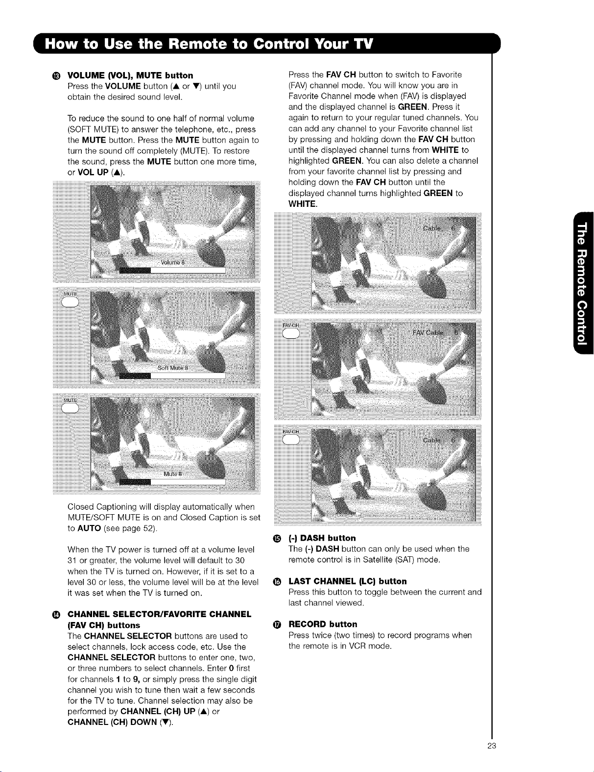
_) VOLUME {VOL), MUTE button
Press the VOLUME button (A or V) until you
obtain the desired sound level.
To reduce the sound to one half of normal volume
(SOFT MUTE) to answer the telephone, etc., press
the MUTE button. Press the MUTE button again to
turn the sound off completely (MUTE). To restore
the sound, press the MUTE button one more time,
or VOL UP (A).
Press the FAV CH button to switch to Favorite
(FAY) channel mode. You will know you are in
Favorite Channel mode when (FAV) is displayed
and the displayed channel is GREEN. Press it
again to return to your regular tuned channels. You
can add any channel to your Favorite channel list
by pressing and holding down the EAV OH button
until the displayed channel turns from WHITE to
highlighted GREEN. You can also delete a channel
from your favorite channel list by pressing and
holding down the FAV OH button until the
displayed channel turns highlighted GREEN to
WHITE.
Closed Captioning will display automatically when
MUTE/SOFT MUTE is on and Closed Caption is set
to AUTO (see page 52).
When the TV power is turned off at a volume level
31 or greater, the volume level will default to 30
when the TV is turned on. However, if it is set to a
level 30 or less, the volume level will be at the level
it was set when the TV is turned on.
CHANNEL SELECTOR/FAVORITE CHANNEL
(FAV CH) buttons
The CHANNEL SELECTOR buttons are used to
select channels, lock access code, etc. Use the
CHANNEL SELECTOR buttons to enter one, two,
or three numbers to select channels. Enter 0 first
for channels I to 9, or simply press the single digit
channel you wish to tune then wait a few seconds
for the TV to tune. Channel selection may also be
performed by CHANNEL (OH) UP (A) or
CHANNEL (CH) DOWN (V).
_t (-) DASH button
The (-) DASH button can only be used when the
remote control is in Satellite (SAT)mode.
(_ LAST CHANNEL (LC) button
Press this button to toggle between the current and
last channel viewed.
(_ RECORD button
Press twice (two times) to record programs when
the remote is in VCR mode.
23
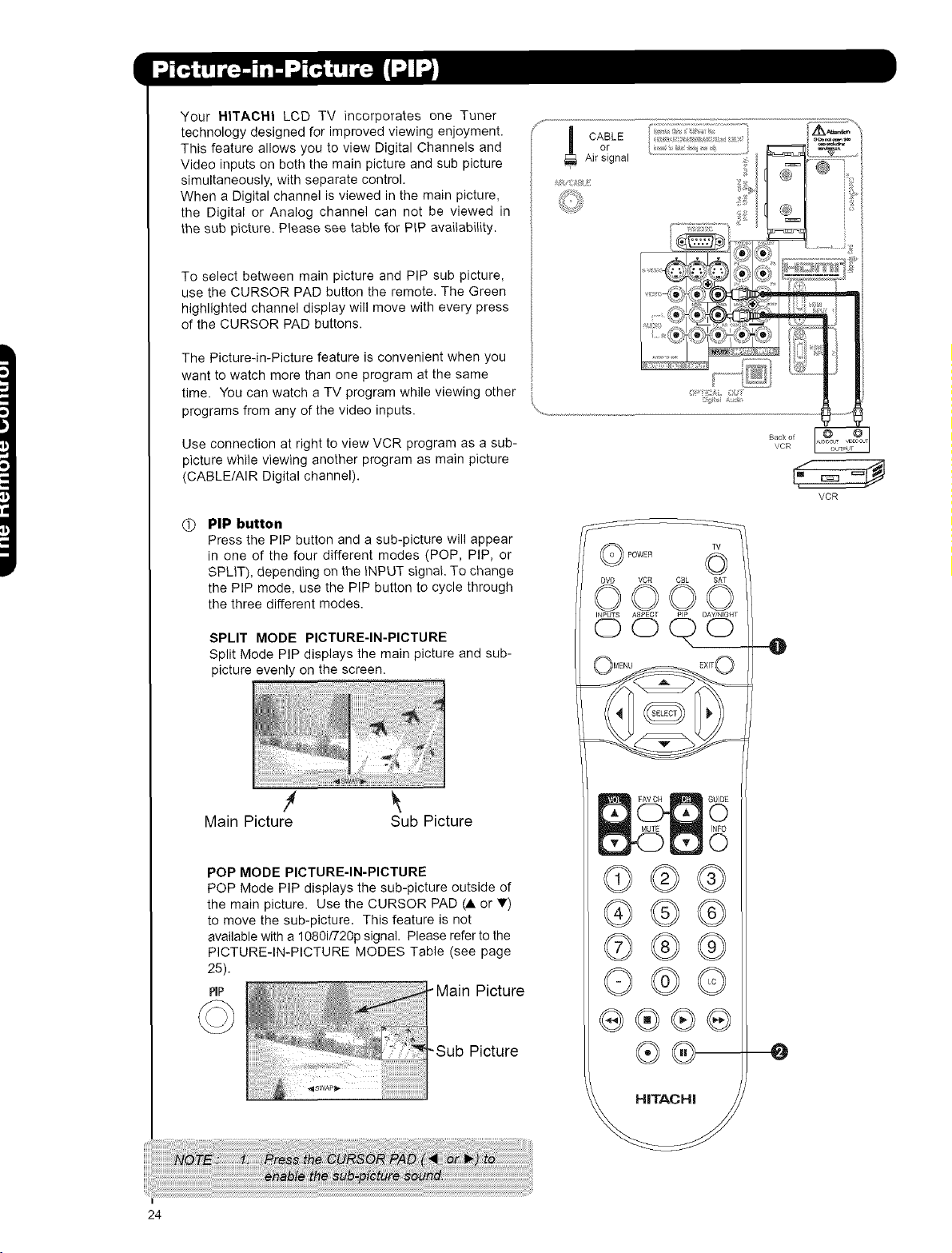
Your HITACHI LCD TV incorporates one Tuner
technology designed for improved viewing enjoyment.
This feature allows you to view Digital Channels and
Video inputs on both the main picture and sub picture
simultaneously, with separate control.
When a Digital channel is viewed in the main picture,
the Digital or Analog channel can not be viewed in
the sub picture. Please see table for PiP availability.
To select between main picture and PIP sub picture,
use the CURSOR PAD button the remote, The Green
highlighted channel display will move with every press
of the CURSOR PAD buttons.
The Picture-in-Picture feature is convenient when you
want to watch more than one program at the same
time. You can watch a TV program while viewing other
programs from any of the video inputs.
Use connection at right to view VCR program as a sub-
picture while viewing another program as main picture
(CABLE/AIR Digital channel).
PiP button
O
Press the PIP button and a sub-picture will appear
in one of the four different modes (POP, PIP, or
SPLIT), depending on the iNPUT signal. To change
the PIP mode, use the PIP button to cycle through
the three different modes.
SPLIT MODE PICTURE-IN-PICTURE
Split Mode PiP displays the main picture and sub-
picture evenly on the screen.
f_
or
CABLE
Airsignal
VCR
DVD VCR CBL SAT
oo©o
INPUTS ASPECT DAY/NIGHT
OO( O O
Main Picture Sub Picture
POP MODE PICTURE-IN-PICTURE
POP Mode PiP displays the sub-picture outside of
the main picture. Use the CURSOR PAD (A or T)
to move the sub-picture. This feature is not
available with a 1080i/720p signal. Please refer to the
PICTURE-IN-PICTURE MODES Table (see page
25).
PIP
24
©®®
®®®
©®®
©®©
®®
O
 Loading...