

Hitachi 61UDX10B, 43FDX11B, 43FDX10B, 53UDX10B Owner’s Manual
PROJECTION COLOR TV
OPERATING GUIDE
IMPORTANT SAFETY INSTRUCTIONS
FIRST TIME USE
THE GENIUS
REMOTE CONTROL
ULTRATEC BIT-MAP
ON-SCREEN DISPLAY
2-4
5-19
20-32
33-60
USEFUL INFORMATION INDEX 61-67
As an ENERGYSTAR ® Partner, Hitachi, Ltd. has determined that this
product meets the ENERGYSTAR® guidelines for energy efficiency.
//_ IMPORTANT
Follow all warnings and instructionsmarked on this projection television.
WARNING
RISK OF ELECTRIC SHOCK
DO NOT OPEN
CAUTION: TO REDUCE THE RISK OF ELECTRIC SHOCK,
DO NOT REMOVE COVER (OR BACK)
NO USER SERVICEABLE PARTS INSIDE
REFER SERVICING TO QUALIFIED SERVICE PERSONNEL
WARNING:
TO REDUCE THE RISK OF FIRE OR ELECTRIC SHOCK, DO NOT
EXPOSE THIS APPARATUS TO RAIN OR MOISTURE.
NOTE: • There are no user serviceable parts inside the television.
• Model and serial numbers are indicated on back side of the television.
• This television is not intended for use in a computer room.
CAUTION: Adjust only those controls that are covered in the instructions, as improper changes or modifications not
expressly approved by HITACHI could void the user's warranty.
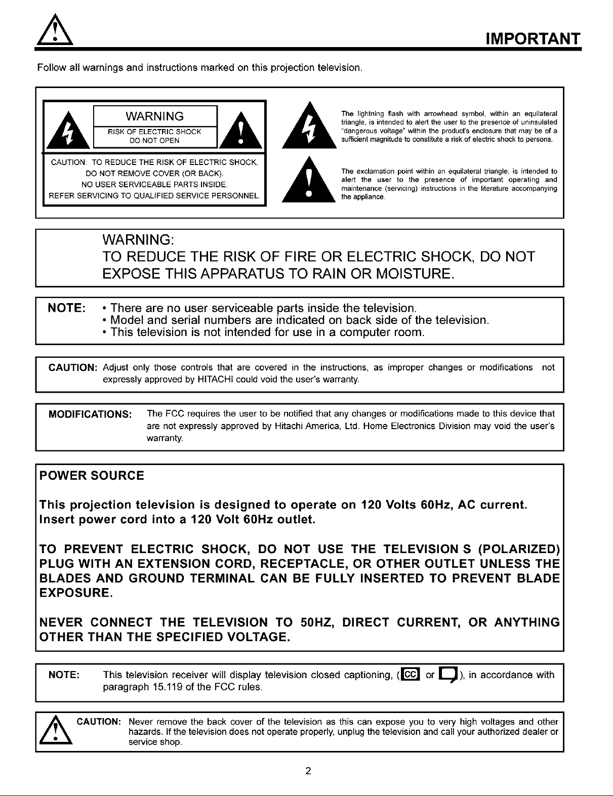
The Iightning flash with arrowhead symbol, within an equilatoral
triangle, is intended to atart the user to the presence of uninsulatad
"dangerous voltage" within the product's enclosure that may be of a
sufficient magnitude to constitute a risk of electric shock to persons¸
The exclamation point within an equilateral triangle, is intended to
alert the user to the presence of important operating and
maintenance (servicing) instructions in the literature accompanying
the appliance
I
I
I
MODIFICATIONS: The FCC requires the user to be notified that any changes or modifications made to this device that
are not expressly approved by Hitachi America, Ltd. Home Electronics Division may void the user's
warranty.
POWER SOURCE
This projection television is designed to operate on 120 Volts 60Hz, AC current.
Insert power cord into a 120 Volt 60Hz outlet.
TO PREVENT ELECTRIC SHOCK, DO NOT USE THE TELEVISION S (POLARIZED)
PLUG WITH AN EXTENSION CORD, RECEPTACLE, OR OTHER OUTLET UNLESS THE
BLADES AND GROUND TERMINAL CAN BE FULLY INSERTED TO PREVENT BLADE
EXPOSURE.
NEVER CONNECT THE TELEVISION TO 50HZ, DIRECT CURRENT, OR ANYTHIN(
OTHER THAN THE SPECIFIED VOLTAGE.
NOTE:
This television receiver will display television closed captioning, (rc_ or [_), in accordance with I
paragraph 15.119 of the FCC rules.
I
I
,_ CAUTION: Never remove the back cover of the television as this can expose you to very high voltages and other I
servicehazards,shop.If the television does not operate properly, unplug the television and call your authorized dealer or
2
SAFETY TIPS
IMPORTANT SAFETY INSTRUCTIONS
CAUTION: • Read these instructions.
• Keep these instructions.
SAFETY POINTS YOU SHOULD KNOW ABOUT
YOUR HITACHI PROJECTION TELEVISION
• Heed ai] warnings.
• Follow all instructions
Our reputation has been built on the quality, performance, and ease of service of HiTACHi televisions.
Safety is also foremost in our minds in the design of these units. To help you operate these products properly, this section illustrates safety tips which
will be of benefit to you. Please read it carefully and apply the knowledge you obtain from it to the proper operation of your HITACHI television.
Please fill out your warranty card and mail it to HiTACHi. This will enable HiTACHi to notify you promptly in the improbable event that a safety
problem should be discovered in your product model.
FOR YOUR PERSONAL SAFETY
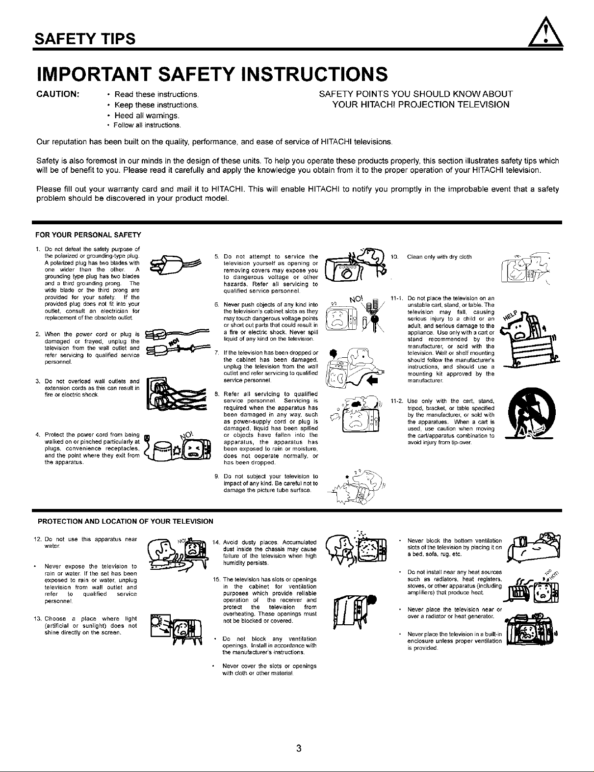
1 DO not defeat the safety purpose of
the polarized or grounding4ype plug
A poiddzed plug has two blades with
one wider than the other A
grounding type plug has two blades
and a third grounding prong¸ The
wide blade or the third prong are
provided for your safety¸ If the
provided plug does not t_t into your
otJtlet, consuR an electrician for
replaceme_ of the obsolete outlet
2 When the power cord or ptug is
damaged or frayed, unptog the
television from the wall outlet and
refer servtoing to qualified service
personnel
3 DO not overload wall outlets and
extension cords as this c_n result in
f_reor electricshock
4 Protect the power cord from being O \
walked on or pinched partidtJla fly at
plugs_ eonvenience receptacEes_
and the point where they e×it from
the apparatus_
5 DO not attempt to service the
television yourself as opening or
removing covers may expose you
to dangerous vottage or other
hazards Refer alt servicing to
qualified service personnel
6.
Never push objects of any kind into
the teEevision's c_binet stots as they
may touch dangerous vo_fege points
or short out pads that could res_t in
a fire Or eidctdo shock¸ Never spill
liquid of any kind on the televidton
Ifthe tefevisidn has been dropped or
the cabinet has been damaged,
unplug the tefevisidn from the wall
outlet and refer servicing to qualified
selvice personnel
Refer all servicing to qualified
service personnel Servicing is
required when the apparatus has
been damaged in any way, such
as power-supply cord or plug is
damaged, liquid has been spHted
or objects have felten into the
apparatus, the apparatus has
been exposed _o rain or moislure,
does not ooperate normally, Or
has been dropped¸
9.
Do not subject your television to
impact of any kind Be careful not to
damage the picture tube surface¸
Clean onlywith dry idoth
11-t Do not place the tetoviston on an
unstable c_rt, stand, or table The
televiston may fell, causing
serious injury to a child Or an
adult, and serious damage to the
appliance Use only with a r_rt or
stand recommended by the
mantJfecturer, or sold with the
television¸ Walt or she_f mounting
should fellow the manufectorer's
instructions, and should USe a
mounting kit approved by the
manufecturer
11-2 Use only with the cart, stand,
tripod, bracket, or table spedfied
by the manotacture_ or sold with
the apparatues t_.,_qena C_rt is
used, use cautton when moving
the carflapparatus combina_on to
avoid injury from tip-ove_
PROTECTION AND LOCATION OF YOUR TELEVISION
12 DO not use lhis apparatus near
water
• Never expose the tetovision to
rain or water If the set has been
exposed to rain or water, unptog
tetovidion from wall outlet and
refer to qualified service
personnel
13 Choose a place where Eight
(artificial or sunlight) does not
shine directly on the screen¸
14 Avoid dusty places Accumu_afed _" _'f_.-_n
dust inside the chassis may cause
feitore of the teidvidton when high
humidity persists¸
15 The television has stots or openings
in the cabinet for ventilabon
purposes which provide reliabto
operation Of the receiver and
protect the television from
overheating These openings must
not be blocked or covered¸
• O0 not block any ventilation
openings Install in accordance with
the manufacturer's instructions
• Never cover the sidts or openings
with idoth or other material
3
°*,,
Never block the bottom ventiidtion
slots of the television by placing it on
a bed, sofa, rtJg, etc
• Do not install near any heat sources ,,_o_,\
such as radiators, heat registers, #'m"r___3 _
stoves,orotherapparatus(inolt_dingt,_j_'_l
amplifiers) that produce heat _
• Never place the television near or
over a radiator or heat generator
• Never p_ace the television in a built-in _l|
enclosure unless proper ventilation
is provided
PROTECTION AND LOCATION OF YOUR TELEVISION
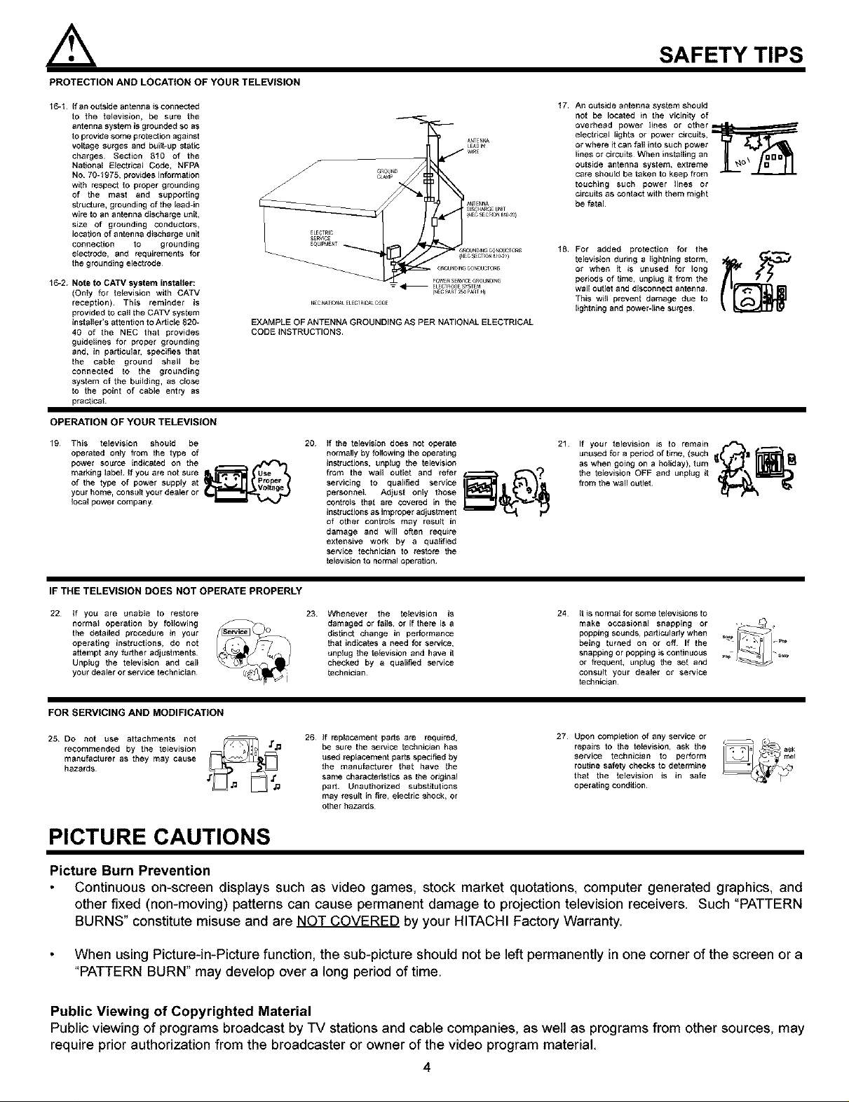
16-1 If an outside antenna is eonnectsd
to the television, be sure the
antenna system is grotJnded so as
to prov_e some protection against
voltsge surges and buig-up static
charges¸ Section 810 of the
National E_ectrieal Code, NFPA
NO 70-1975, prov_es information
with respect to proper grotJndieg
of the mast and supporting
structure, grounding of the lead-in
wire to an antenna discharge unit,
size of grounding eonduetsrs,
Iocagon of antenna discharge unit
connection to grounding
electrode, and requirements for
the grotJnding electrode
16-2. Note to CATV system installer:
(Onty for teievieien with CATV
reception)¸ This reminder is
provided to call the CATV system
iestsllerie attention to Article 820-
40 of the NEC that provides
gtJideliees for proper grounding
and, in pargoiear, specifies that
the cable ground shall be
connected to the grounding
system of the building, as close
to the point of cable entry as
pracgcal
OPERATION OF YOUR TELEVISION
19 This television should be
operated only from the type of
power source indicated on the
marking iebeL If you are not sure
of _he type of power supply at
your home_ eonstJE_your dea_er or
tocal p_wer eompany_
20 If the tsievision does not operate
normally by following the operating
instructions, unplug the tsievi$ion
from the wall outlet and refer
servicing to qualified service
personnel Adjust only those
controls that are covered in the
instructions as improper _djustment
of other controls may result in
damage and will often requ_e
extensive work by a qualified
se_ice technician to restore lhe
televieion to normal operation¸
SAFETY TIPS
17
An outside antenna system should
not be located in the vicinity of
overhead power tines or Other_
electrical lights or power circuits,
or where it can foil into such power
lines or circuits¸ When installing an
outside antenna system, extreme
care shoutd be taken to keep from
touching such power lines or
circuits as contact with them might
be falal
18
For added protection for the
television during a lightning storm,
or when it is unused for long
periods of time, unplug it from the
wail outlet and disconnect antenna¸
This will prevent damage due to
ligfoning and power-line surges¸
21 If your television is to female
unused for a period of time, (such I
as whengoingonaholidsy),tum _(_ _11_
the television OFF and unplug it
from the wa,l outlet _dll_
IF THE TELEVISION DOES NOT OPERATE PROPERLY
22 If yOU are unable to restore
normal operation by toliewing
the detsiied procedure in your
operating instructions, do not
attempt any further adjustments¸
Unplug the teievieion and calt
your dealer or service technician¸
23 Whenever the te[evieion is
damaged or foiie, or if there is a
distinct change in performance
that indieafe$ a need for service,
_nplug the television and have it
checked by a qualdfed service
technician
24 It i$ normal for some teievieions to
make occasional snapping or -_
being turned on or off If the
popo,ngsound,,pa,t,cuier,ywhen
snapping or popping is continuous
or frequent, unplug the set and
COnSUg your dealer ol service
technician
FOR SERVICING AND MODIFICATION
27
25 DO not use attachments not
recommended by the television
manuf_ctorer as they may cause
hazards¸
26 If replacement parts are required,
be sure the service teehnic, lan has
used redt_cemenl parts specified by
the manufocto_er that have the
same characteristics as the original
part¸ Unauthorized substitutions
rosy resort in f_re, electric shock, or
other hazards
Upon completion of any selvice or
repairs to the te{evision, ask the
service technician to perform
routine safety checks to determine
that the television _s in safe
operating condition¸
PICTURE CAUTIONS
Picture Burn Prevention
Continuous on-screen displays such as video games, stock market quotations, computer generated graphics, and
other fixed (non-moving) patterns can cause permanent damage to projection television receivers. Such "PATTERN
BURNS _constitute misuse and are NOT COVERED by your HITACHI Factory Warranty.
When using Picture-in-Picture function, the sub-picture should not be left permanently in one corner of the screen or a
"PATTERN BURN" may develop over a long period of time.
Public Viewing of Copyrighted Material
Public viewing of programs broadcast by "iV stations and cable companies, as well as programs from other sources, may
require prior authorization from the broadcaster or owner of the video program material.
4
ACCESSORIES
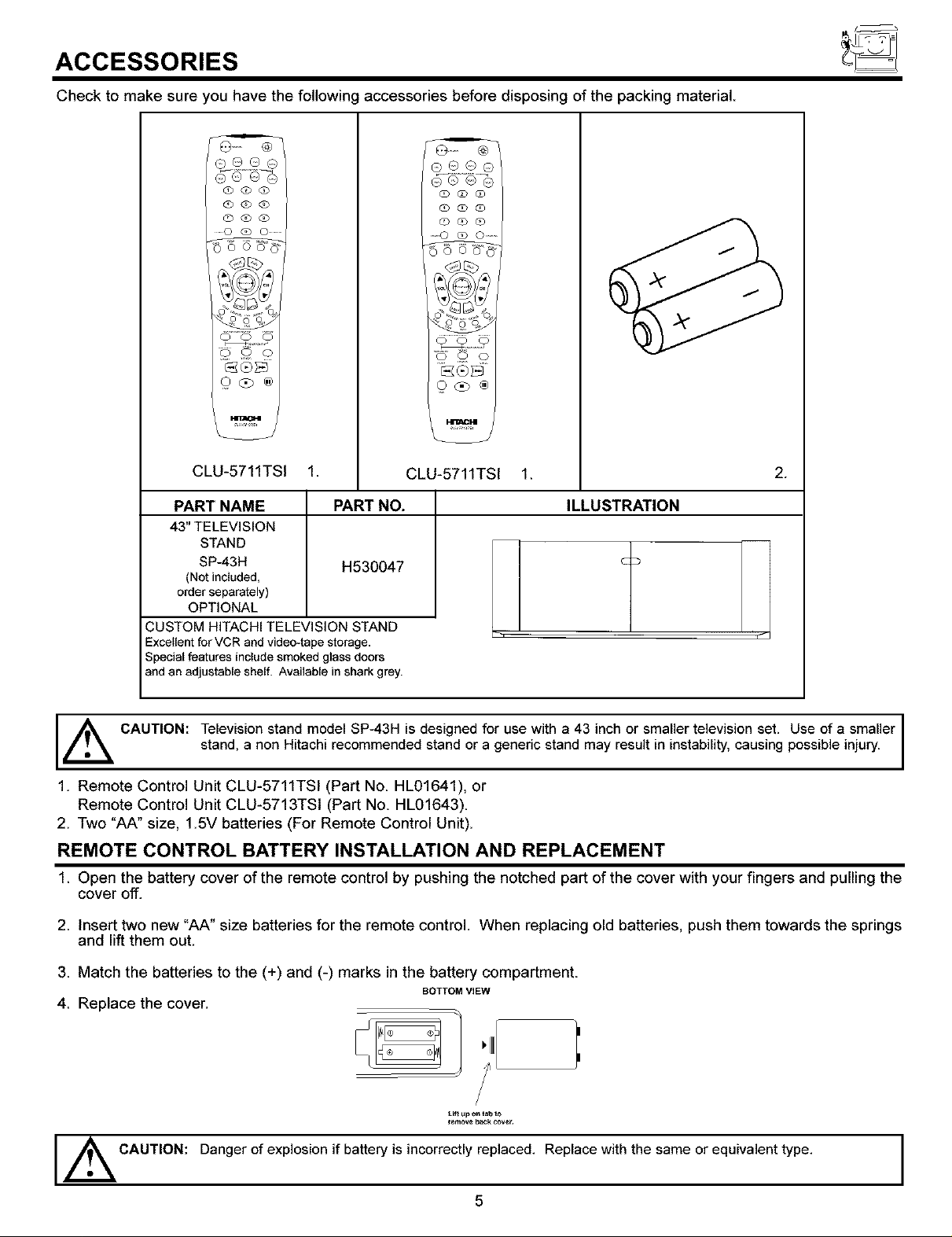
Check to make sure you have the following accessories before disposing of the packing material
(1) 600
@ (b (]D
(Z%q0 (!)
......0(300 ........
/,4 tt : _);/,. /
Q@o ®
CLU-5711TSI 1.
PART NAME PART NO.
43" TELEVISION
STAND
SP-43H
(Not included,
orderseparately)
OPTIONAL
CUSTOM HITACHI TELEVISION STAND
Excellent for VCR and video-tape storage.
Special features include smoked glass doors
and an adjustable shelf. Available in shark grey.
H530047
0@o
Q_o
o o o
(2 (?o ®
CLU-5711TSI 1.
2.
ILLUSTRATION
_ CAUTION: Television stand model SP-43H is designed for use with a 43 inch or smaller television set. Use of a smaller
stand, a non Hitachi recommended stand or a generic stand may result in instability, causing possible injury.
1. Remote Control Unit CLU-5711TSI (Part No HL01641), or
Remote Control Unit CLU-5713TSI (Part No. HL01643).
2. Two "AA" size, 1.5V batteries (For Remote Control Unit).
REMOTE CONTROL BATTERY INSTALLATION AND REPLACEMENT
1 Open the battery cover of the remote control by pushing the notched part of the cover with your fingers and pulling the
cover off.
2 Insert two new "AA" size batteries for the remote control. When replacing old batteries, push them towards the springs
and lift them out.
3 Match the batteries to the (+) and (-) marks in the battery compartment
BOTTOM ViEW
4 Replace the cover.
t.lft up o_ tz,b to
_en,ove b_$: cove:.
Danger ofexplosion if battery is incorrectly replaced. Replace with the same orequivalent type.
CAUTION:
5
I
HOW TO SET UP YOUR NEW HITACHI PROJECTION TV
ANTENNA
Unless your TV is connected to a cable TV system or to a centralized antenna system, a good outdoor color TV antenna is
recommended for best performance. However, if you are located in an exceptionally good signal area that is free from interference and
multiple image ghosts, an indoor antenna may be sufficient.
LOCATION
Select an area where sunlight or bright indoor illumination will not fall directly on the picture screen. Also, be sure that the location
selected allows a free flow of air to and from the perforated back cover of the set.
To avoid cabinet warping, cabinet color changes, and increased chance of set failure, do not place the TV where temperatures can
become excessively hot, for example, in direct sunlight or near a heating appliance, etc.
VIEWING
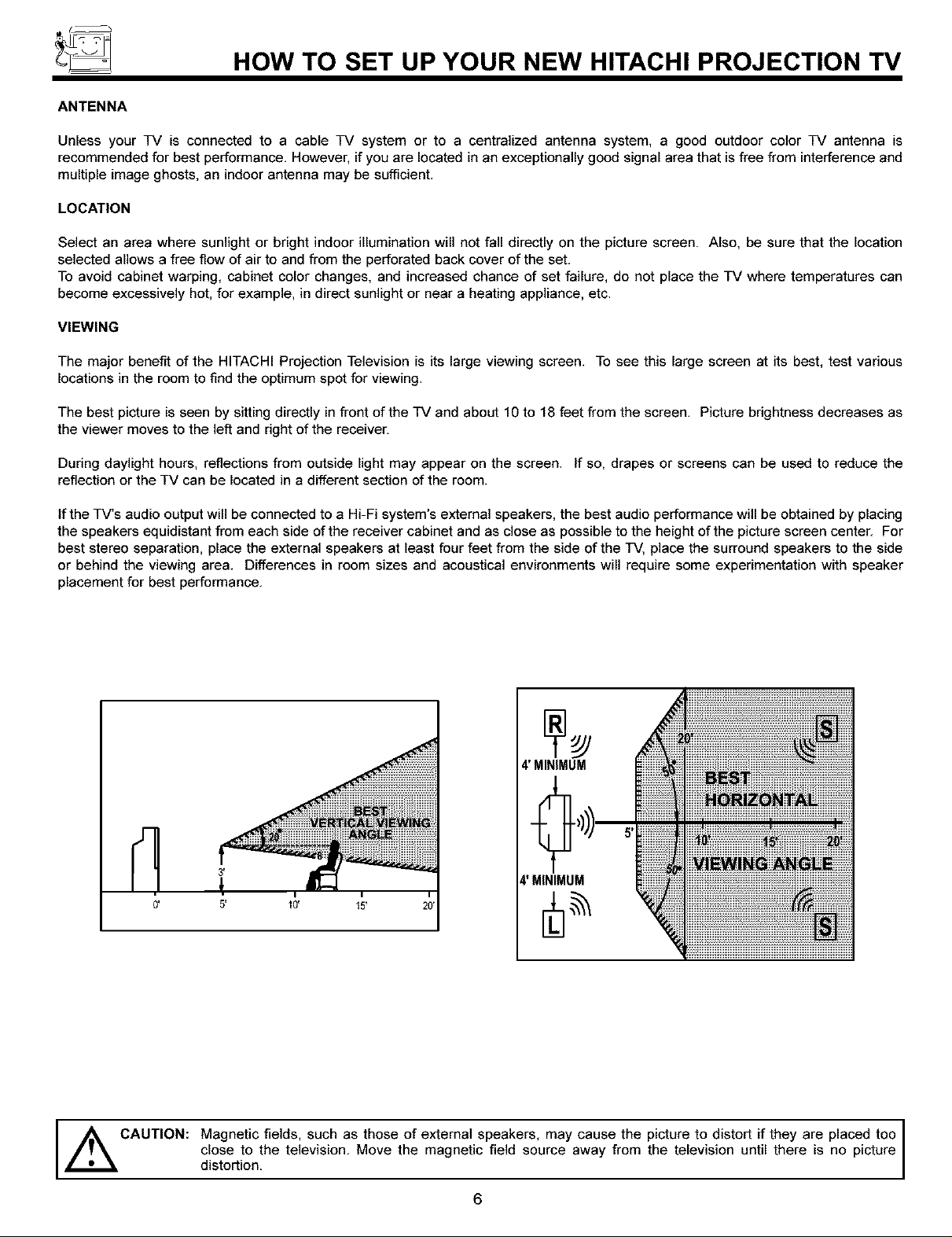
The major benefit of the HITACHI Projection Television is its large viewing screen. To see this large screen at its best, test various
locations in the room to find the optimum spot for viewing.
The best picture is seen by sitting directly in front of the TV and about 10 to 18 feet from the screen. Picture brightness decreases as
the viewer moves to the left and right of the receiver.
During daylight hours, reflections from outside light may appear on the screen. If so, drapes or screens can be used to reduce the
reflection or the TV can be located in a different section of the room.
ffthe TV's audio output will be connected to a Hi-Fi system's external speakers, the best audio performance will be obtained by placing
the speakers equidistant from each side of the receiver cabinet and as close as possible to the height of the picture screen center. For
best stereo separation, place the external speakers at least four feet from the side of the TV, place the surround speakers to the side
or behind the viewing area. Differences in room sizes and acoustical environments will require some experimentation with speaker
placement for best performance.
1
4' MINIMUM
4'MINIMUM
CAUTION: Magnetic fields, such as those of external speakers, may cause the picture to distort if they are placed too
close to the television. Move the magnetic field source away from the television until there is no picture
distortion.
6
HOOK-UP CABLES AND CONNECTORS
Most video/audio connections between components can be made with shielded video and audio cables that have phono connectors.
For best performance, video cables should use 75-Ohm coaxial shielded wire. Cables can be purchased from most stores that sell
audio/video products. Below are illustrations and names of common connectors. Before purchasing any cables, be sure of the output
and input connector types required by the various components and the length of each cable.
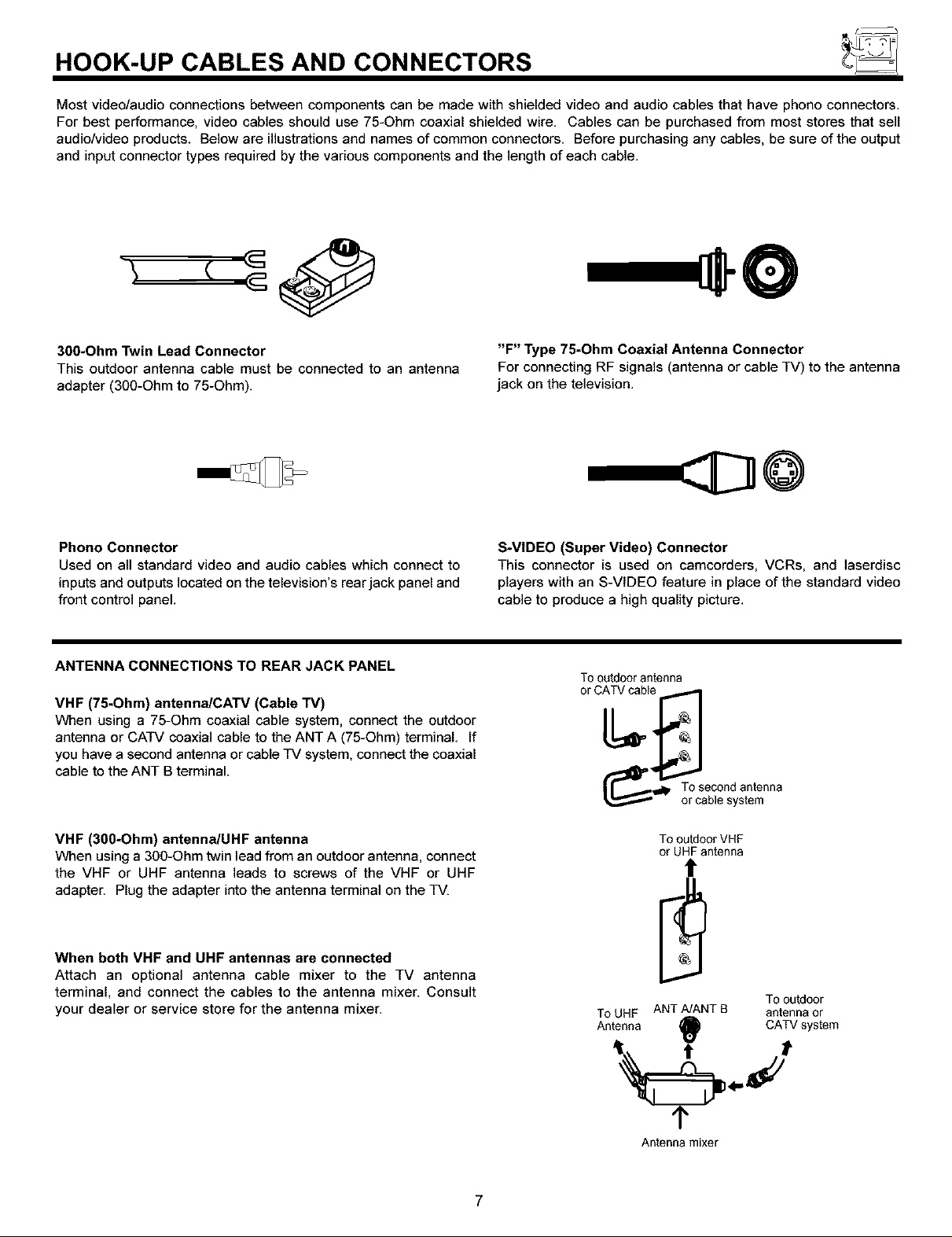
30O*Ohm Twin Lead Connector
This outdoor antenna cable mast be connected to an antenna
adapter (300-Ohm to 75-Ohm).
Phono Connector
Used on all standard video and audio cables which connect to
inputs and outputs located on the television's rear jack panel and
front control panel.
ANTENNA CONNECTIONS TO REAR JACK PANEL
VHF (75-Ohm) antenna/CATV (Cable TV)
When using a 75-Ohm coaxial cable system, connect the outdoor
antenna or CATV coaxial cable to the ANT A (75-Ohm) terminal. If
you have a second antenna or cable TV system, connect the coaxial
cable to the ANT B terminal.
"F" Type 75-Ohm Coaxial Antenna Connector
For connecting RF signals (antenna or cable TV) to the antenna
jack on the television.
@
S-VIDEO (Super Video) Connector
This connector is used on camcorders, VCRs, and ]aserdisc
players with an S-VIDEO feature in place of the standard video
cable to produce a high quality picture.
Tooutdoorantenna
('_'_=_ Tosecondantenna
or cablesystem
VHF (30O*Ohm) antenna/UHF antenna
When using a 300-Ohm twin lead from an outdoor antenna, connect
the VHF or UHF antenna leads to screws of the VHF or UHF
adapter. Plug the adapter into the antenna terminal on the TV.
When both VHF and UHF antennas are connected
Attach an optional antenna cable mixer to the TV antenna
terminal, and connect the cables to the antenna mixer. Consult
your dealer or service store for the antenna mixer.
To outdoor VHF
or UHF antenna
t
Tooutdoor
ToUHF ANTA/ANT B antennaor
Antenna
9 C, aystem
1'
Antenna mixer
7
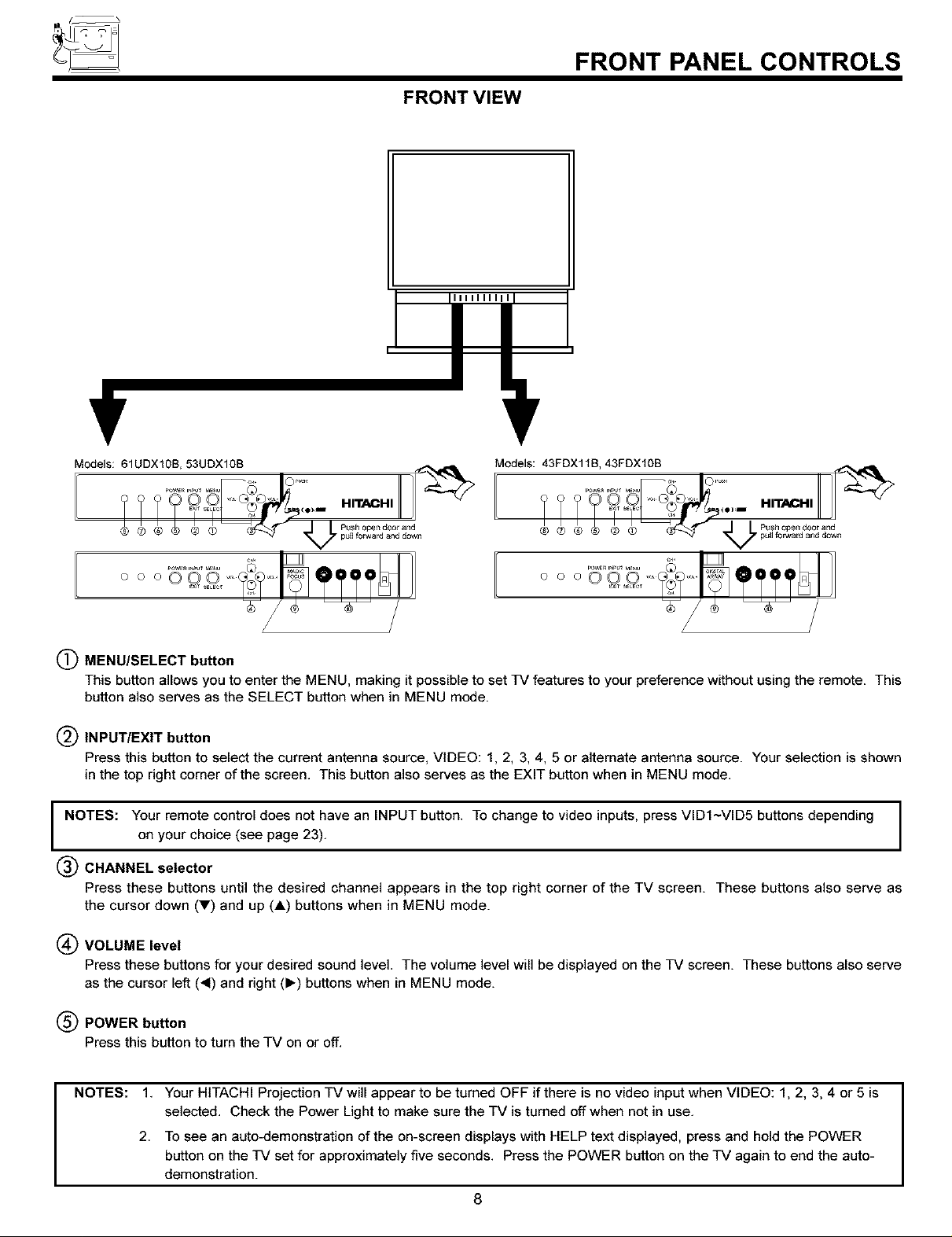
FRONT VIEW
FRONT PANEL CONTROLS
Modets: 61UDX10B, 53UDX108
oooO0 0 ....
(_ MENU/SELECT button
This button allows you to enter the MENU, making it possible to set 17/features to your preference without using the remote. This
button also serves as the SELECT button when in MENU mode.
(_ INPUT/EXIT button
Press this button to select the current antenna source, VIDEO: 1, 2, 3, 4, 5 or alternate antenna source. Your selection is shown
in the top right corner of the screen. This button also serves as the EXIT button when in MENU mode.
NOTES: Your remote control does not have an INPUT button. To change to video inputs, press VIDI~VlD5 buttons depending
on your choice (see page 23).
(_) CHANNEL selector
Press these buttons until the desired channel appears in the top right corner of the TV screen. These buttons also serve as
the cursor down (_') and up (A) buttons when in MENU mode.
_×l_ SELEC_
Models: 43FDX118, 43FDXIOB
HITACHI _
oooo9,2 TTT I ]1
/
(_) VOLUME level
Press these buttons for your desired sound level. The volume level will be displayed on the TV screen. These buttons also serve
as the cursor left (_1) and right (1_) buttons when in MENU mode.
(_ POWER button
Press this button to turn the TV on or off.
NOTES:
1. Your HITACHI Projection TV will appear to be turned OFF if there is no video input when VIDEO: 1, 2, 3, 4 or 5 is
selected. Check the Power Light to make sure the TV is turned off when not in use.
2. To see an auto-demonstration of the on-screen displays with HELP text displayed, press and hold the POWER
button on the 17/set for approximately five seconds. Press the POWER button on the TV again to end the auto-
demonstration.
8

FRONT PANEL CONTROLS
(_) POWER light
You will see a red light when the TV is turned on.
(_ PERFECT PICTURE sensor
The Perfect Picture sensor will make automatic picture adjustments depending on the amount of light in the room to give the best
picture. (see page 54)
(_) REMOTE CONTROL sensor
Point your remote at this area when selecting channels, adjusting volume, etc.
(_ DIGITAL ARRAY (Model: 43FDXlOB/43FDX11B)
MAGIC FOCUS (Models: 53UDX10/61UDX10B)
Use this button to adjust your picture quality to optimum performance. (see pages 42 and 43)
(_) FRONT INPUT JACKS (for VIDEO: 3)
Use these audio/video jacks for a quick hook-up from a camcorder or VCR to instantly view your favorite show or new recording.
Press the INPUT button until VIDEO: 3 appears in the top right corner of the TV screen. If you have mono sound, insert the audio
cable into the left audio jack.
9
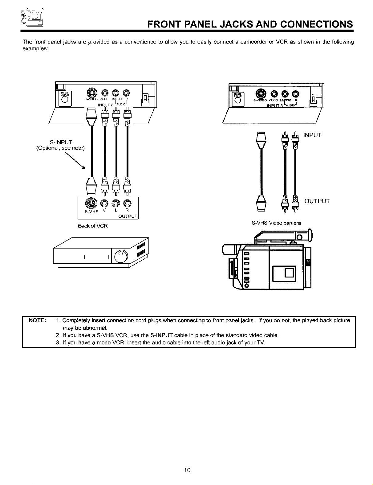
FRONT PANEL JACKS AND CONNECTIONS
The front panel jacks are provided as a convenience to allow you to easily connect a camcorder or VCR as shown in the following
examples:
S.V_DEO VIDEO
ii LAUD_O]
J
@ooo
S-INPUT
(Optional, see note)
l l! INPUT
OUTPUT
S-VHS V
Back c_ VCR
UT
S-VHS Video camera
NOTE: 1, Completely insert connection cord plugs when connecting to front panel jacks. If you do not, the played back picture
may be abnormal,
2, If you have a S-VHS VCR, use the S-INPUT cable in place of the standard video cable.
3, If you have a mono VCR, insert the audio cable into the left audio jack of your TV.
10
REAR PANEL JACKS
AUDIOTO HI-FI
R L
@@,
®
ANTA
TO
CONVERTER
ANTB
(!i) ®
"S-VtOE0 S-VtOE0
66
VIDEO VIDEO
@
(MONO)<
AUDI0
INPUT1
®
CO
AUDIO AUDIO
INPUT2 INPUT4
@ C
c
AUDIO AU[
INPUT5 MON
Ot
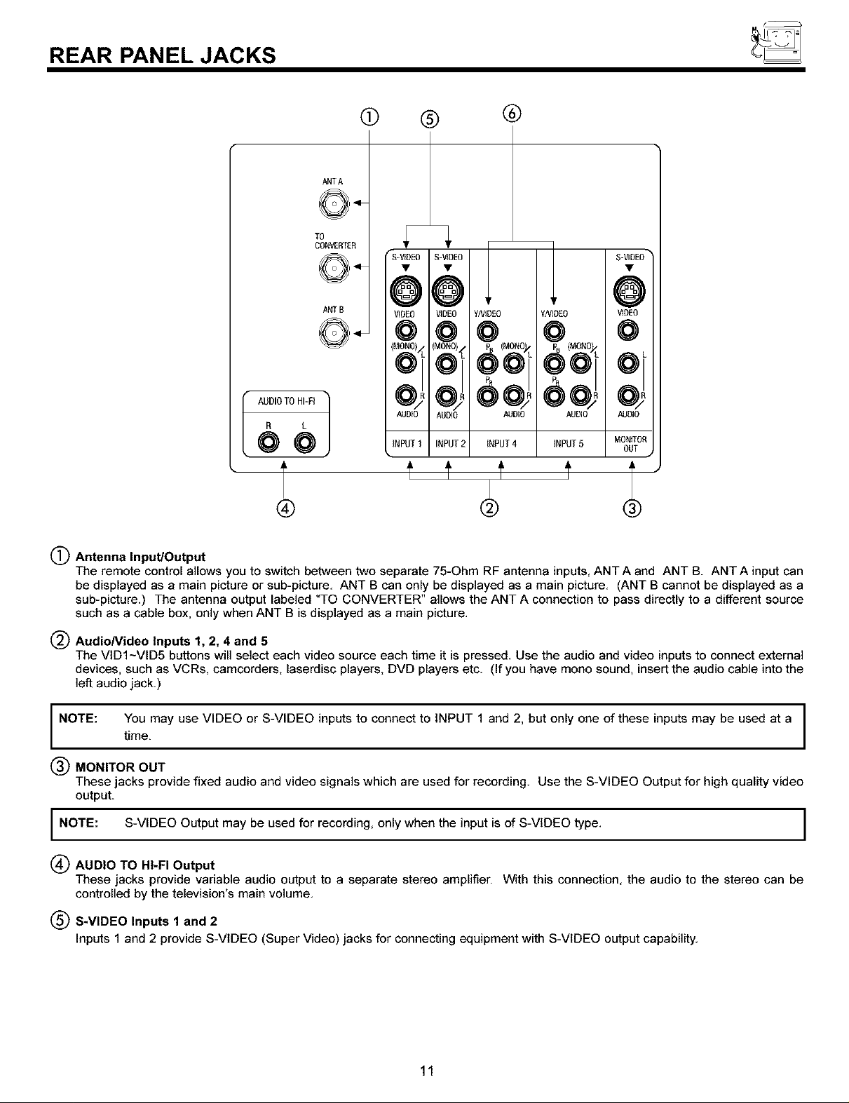
(_ Antenna Input/Output
The remote control allows you to switch between two separate 75-Ohm RF antenna inputs, ANT A and ANT B. ANT A input can
be displayed as a main picture or sub-picture. ANT B can only be displayed as a main picture. (ANT B cannot be displayed as a
sub-picture.) The antenna output labeled "TO CONVERTER" allows the ANT A connection to pass directly to a different source
such as a cable box, only when ANT B is displayed as a main picture.
(_ AudioNideo Inputs 1, 2, 4 and 5
The VtDI~VID5 buttons will select each video source each time it is pressed. Use the audio and video inputs to connect external
devices, such as VCRs, camcorders, laserdisc players, DVD players etc. (If you have mono sound, insert the audio cable into the
]eft audio jack.)
NOTE: You may use VIDEO or S-VIDEO inputs to connect to INPUT 1 and 2, but only one of these inputs may be used at a I
time.
MONITOR OUT
These jacks provide fixed audio and video signals which are used for recording. Use the S-VIDEO Output for high quality video
output.
I NOTE: S-VIDEO Output may be used for recording, only when the input is of S-VIDEO type. I
(_ AUDIO TO HI-FI Output
These jacks provide variable audio output to a separate stereo amplifier. With this connection, the audio to the stereo can be
controlled by the television's main volume.
(_ S-VIDEO Inputs 1 and 2
Inputs 1 and 2 provide S-VIDEO (Super Video) jacks for connecting equipment with S-VIDEO output capability.
I
I
I
11
REAR PANEL JACKS
Component: Y-PBPR Inputs
Inputs 4 and 5 provide Y-PBPR jacks for connecting equipment with this capability, such as a DVD player or Set Top Box. You may
use standard video signal for INPUT:4 and 5.
NOTES: 1. Your component outputs may be labeled Y, B-Y, and R-Y. In this case, connect the components B-Y output to the TV's PB input and
the components R-Y output to the TV's PR input.
2. Your component outputs may be labeled Y-CBC R. In this case, connect the component C B output to the TV's PB input and the
component CR output to the TV's PR input.
3. It may be necessary to adjust TINT to obtain optimum picture quality when using the Y-PBPR inputs. (See pages 53 and 54)
4. To ensure no copyright infringement, the MONITOR OUT output will be abnormal, when using the Y-PBPR jacks.
5. VVnen using Y-PBPR input, only 480i signal can be viewed as a sub-picture.
6. Input 4 and 5 (YNIDEO) can be used for standard video input.
12
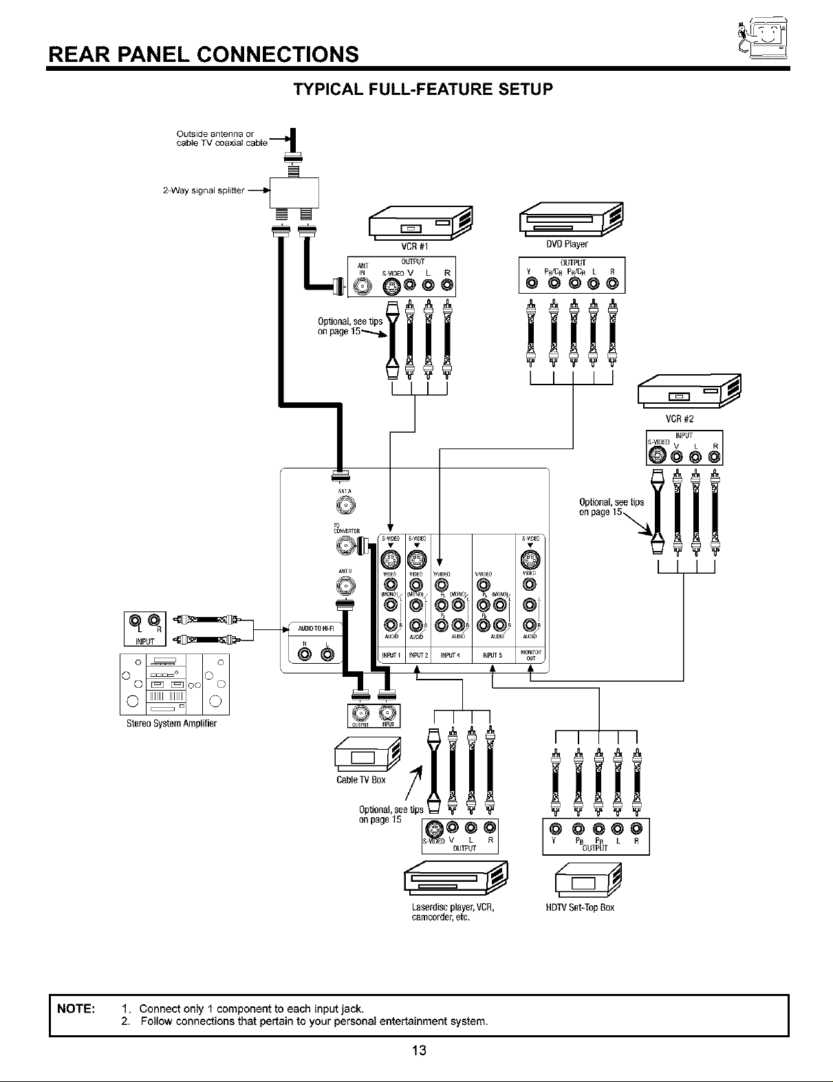
REAR PANEL CONNECTIONS
TYPICAL FULL-FEATURE SETUP
2=Waysignalsplitter
VCR#1
L i,_= °#
Q Q**
!?"
, @
AUDI0 A_I0 NJD_
OVOP_yer
Y P_]CB PR/Cn L R
OUTPUT ]
@ @@@O
iiiii
I I I
OptiOnal,seetips
@
NOTE:
StereoSystemAmplifier
CableTVBox
0pt_0nal,seetips
onpage15
Laserdiseplayer,VCR,
eamcorder,etc.
1. Connect only 1 component to each input jack.
2. Follow connections that pertain to your personal entertainment system.
13
I I I I
iiiii
Y PB PR L R
@@@@@]
OUTPUT
HDTVSet-TopBox
I
TIPS ON REAR PANEL CONNECTIONS
TIPS ON REAR PANEL CONNECTIONS
S-VIDEO connections are provided for high performance laserdisc players, VCRs etc. that have this feature. Use these connections
in place of the standard video connection if your device has this feature.
If your device has only one audio output (mono sound), connect it to the left audio jack on the television.
Refer to the operating guide of your other electronic equipment for additional information on connecting your hook-up cables.
A single VCR can be used for VCR #1 and VCR #2, but note that a VCR cannot record its own video or line output (INPUT: 1 in the
example on page 13). Refer to your VCR operating guide for more information on line input-output connections.
You may use VIDEO or S-VIDEO inputs to connect to Input 1 or Input 2, but only one of these may be used at a time.
Connect only 1 component (VCR, DVD player, camcorder, etc.) to each input jack.
COMPONENT: Y-PBPR (Input 4 &5) connections are provided for high performance components, such as DVD players and set-
top-boxes. Use these connections in place of the standard video connection if your device has this feature.
Your component outputs may be labeled Y, B-Y, and R-Y. In this case, connect the components B-Y output to the TV's PB input
and the components R-Y output to the TV's PR input.
Your component outputs may be labeled Y-CBC R. In this case, connect the components CB output to the TV's PB input and the
components C R output to the TV's PR input.
You may use standard video signal for INPUT:4 and 5.
It may be necessary to adjust TINT to obtain optimum picture quality when using the Y-PBPR inputs. (See pages 53 and 54)
To ensure no copyright infringement, the MONITOR OUT output will be abnormal, when using the Y-PBPR jacks.
14
CONNECTING EXTERNAL AUDIO SOURCES
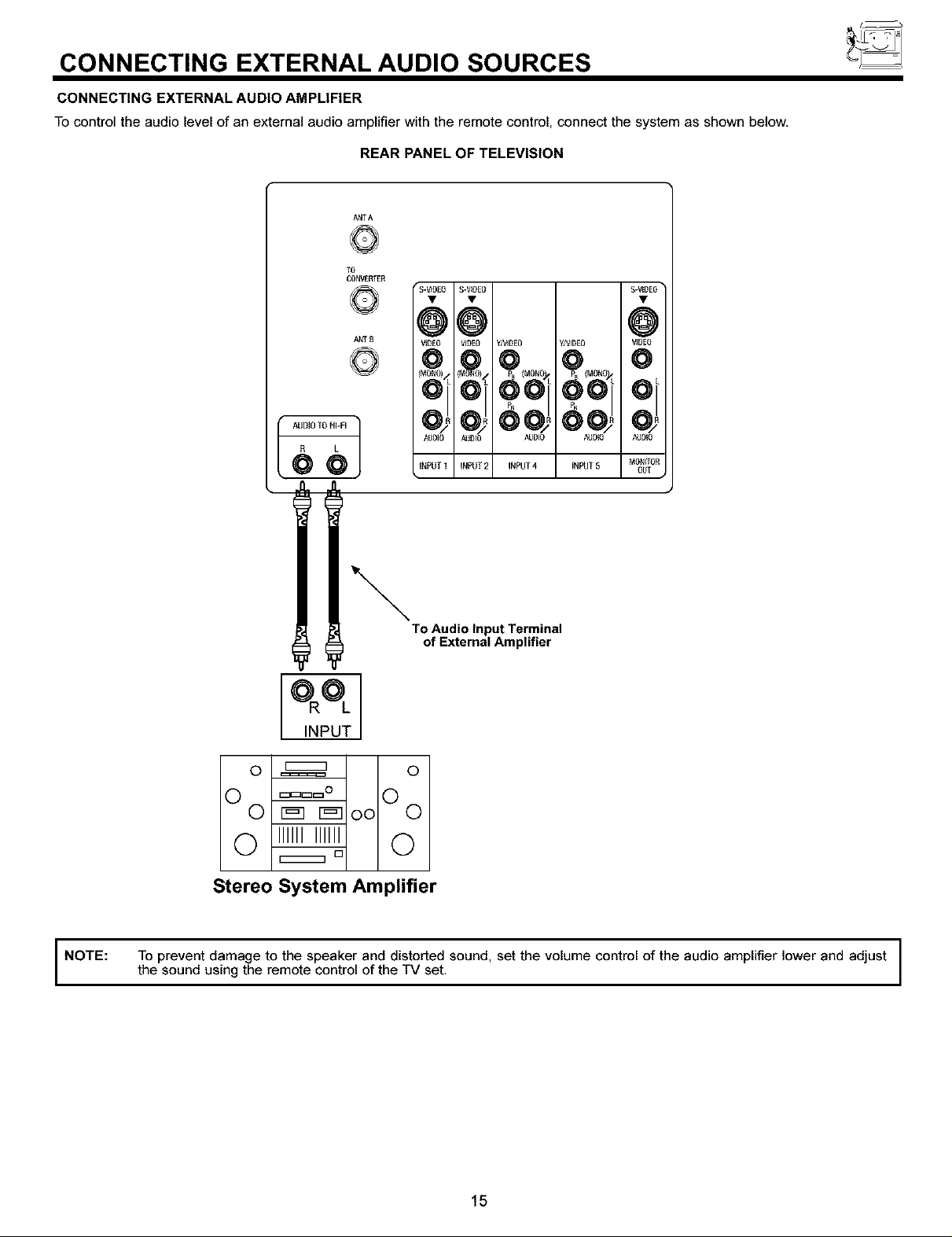
CONNECTING EXTERNAL AUDIO AMPLIFIER
To control the audio level of an external audio amplifier with the remote control, connect the system as shown below,
REAR PANEL OF TELEVISION
ANTA
TO
CONVE_ER
S-VID£0• S-_0E0• $ ]
ANT B
@@
VIOE0 VIOE0 yA_0E0 y/V_D£0 O /
AUDIO AUDIO AUDIO AUDIO
INPUT 1 iNPUT2 iNPUT4 iNPUT5
To Audio Input Terminal
of External Amplifier
INPUT
O _ ©
v r_q r_q oo v
© IlllllIlllll ©
[]
Stereo System Amplifier
NOTE: To prevent damage to the speaker and distorted sound, set the volume control of the audio amplifier lower and adjust
the sound using the remote control of the TV set,
15
CONNECTING EXTERNAL VIDEO SOURCES
The exact arrangement you use to connect the VCR, camcorder, laserdisc player, DVD player, or HDTV Set Top Box to your TV set is
dependent on the model and features of each component. Check the owner's manual of each component for the location of video
and audio inputs and outputs.
The following connection diagrams are offered as suggestions. However, you may need to modify them to accommodate your
particular assortment of components and features. For best performance, video and audio cables should be made from coaxial
shielded wire.
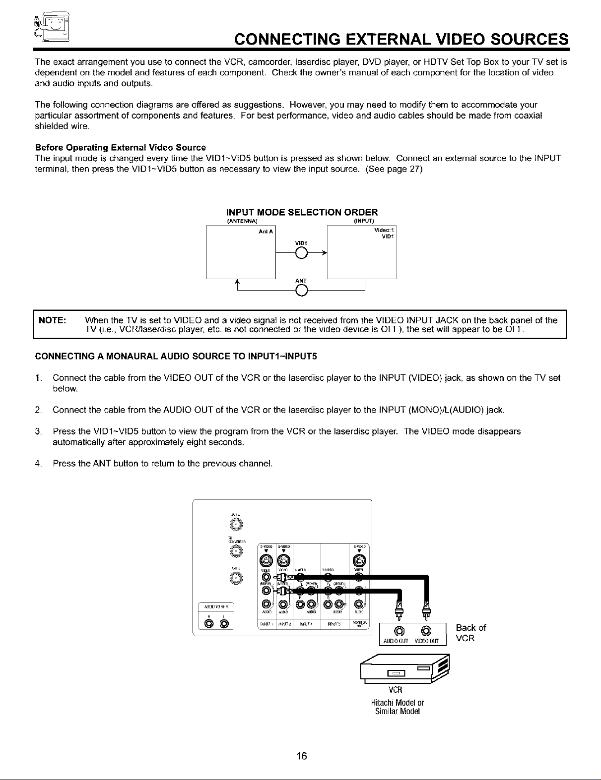
Before Operating External Video Source
The input mode is changed every time the VIDI~VlD5 button is pressed as shown below. Connect an external source to the INPUT
terminal, then press the VlDI-VlD5 button as necessary to view the input source. (See page 27)
INPUT MODE SELECTION ORDER
(ANTENNA) (INPUT)
AntA
A ANT
NOTE:
CONNECTING A MONAURAL AUDIO SOURCE TO INPUTI-INPUT5
1. Connect the cable from the VIDEO OUT of the VCR or the laserdisc player to the INPUT (VIDEO) jack, as shown on the TV set
below.
2. Connect the cable from the AUDIO OUT of the VCR or the laserdisc player to the INPUT (MONO)/L(AUDIO) jack.
3. Press the VlDI~VID5 button to view the program from the VCR or the laserdisc player. The VIDEO mode disappears
automatically after approximately eight seconds.
4, Press the ANT button to return to the previous channel,
When the TV is set to VIDEO and a video signal is not received from the VIDEO INPUT JACK on the back panel of the I
TV (i.e., VOR/laserdisc player, etc. is not connected or the video device is OFF), the set will appear to be OFF.
To
©
88 @
I
I
16
@ @
AUDIOOUT VIDEOotr{
VCR
HitachiModelor
SimilarModel
Back of
VCR
CONNECTING EXTERNAL VIDEO SOURCES
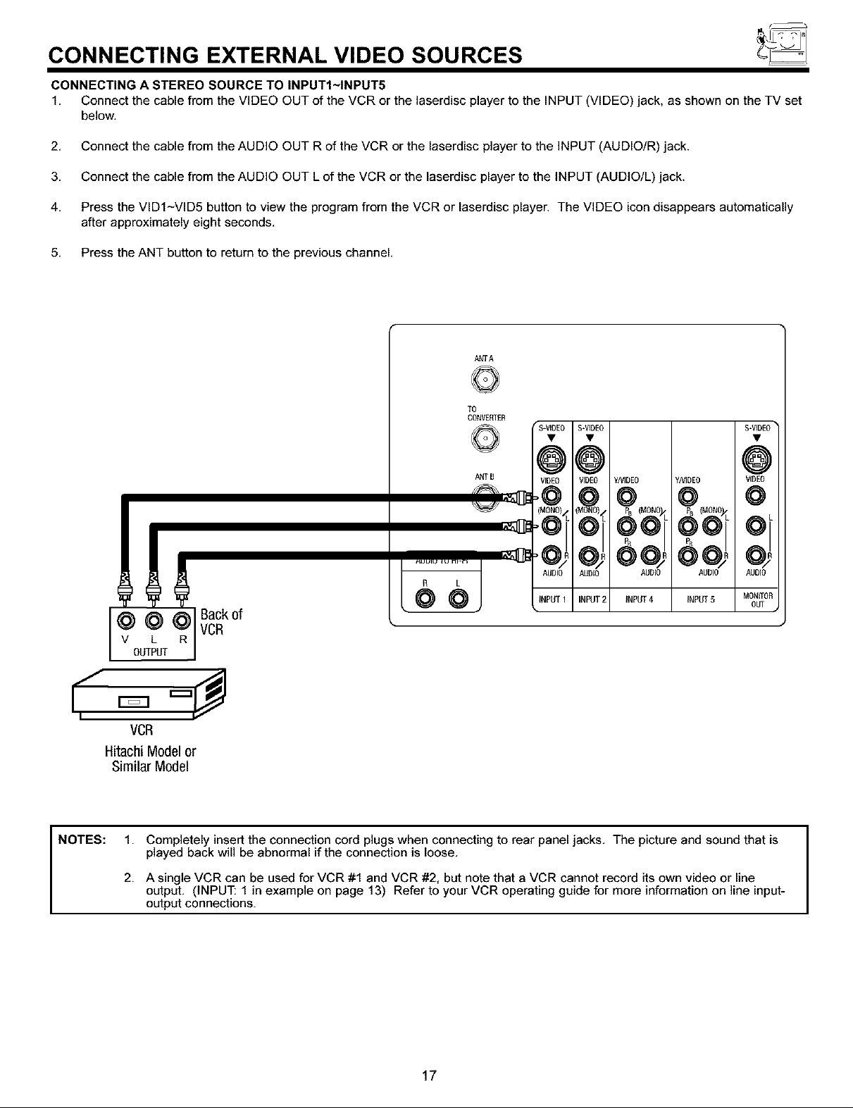
CONNECTING A STEREO SOURCE TO INPUTI-INPUT5
1. Connect the cable from the VIDEO OUT of the VCR or the laserdisc player to the INPUT (VIDEO) jack, as shown on the TV set
below.
2. Connect the cable from the AUDIO OUT R of the VCR or the laserdisc player to the INPUT (AUDIO/R) jack.
3. Connect the cable from the AUDIO OUT Lof the VCR or the laserdisc player to the INPUT (AUDIO/L) jack.
4. Press the VIDI~VID5 button to view the program from the VCR or laserdisc player. The VIDEO icon disappears automatically
after approximately eight seconds.
5. Press the ANT button to return to the previous channel.
ANTA
TO
CONVEFffER
NOTES:
ANTB
R L
@ @ @ Back0f
v L R
OUTPUT
VCR
VCR
Hitachi Model or
Similar Model
1. Completely insert the connection cord plugs when connecting to rear panel jacks. The picture and sound that is
played back will be abnormal if the connection is loose.
2. A single VCR can be used for VCR #1 and VCR #2, but note that a VCR cannot record its own video or line
output. (INPUT: 1 in example on page 13) Refer to your VCR operating guide for more information on line input-
output connections.
MONITOF
OUT
17
CONNECTING EXTERNAL VIDEO SOURCES
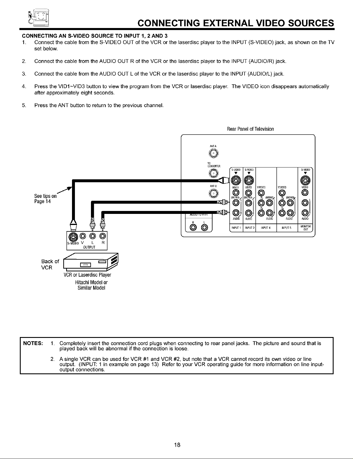
CONNECTING AN S-VIDEO SOURCE TO INPUT 1, 2 AND 3
1. Connect the cable from the S-VIDEO OUT of the VCR or the laserdisc player to the INPUT (S-VIDEO) jack, as shown on the TV
set below.
2. Connect the cable from the AUDIO OUT R of the VCR or the laserdisc player to the INPUT (AUDIO/R) jack.
3. Connect the cable from the AUDIO OUT L of the VCR or the laserdisc player to the INPUT (AUDIO/L) jack.
4. Press the VIDI~VID3 button to view the program from the VCR or laserdisc player. The VIDEO icon disappears automatically
after approximately eight seconds.
5. Press the ANT button to return to the previous channel.
RearPanelofTelevision
Seetipson
Page14
NOTES:
V L R
0Lf[PL_
Oac.
VCR _
VCRor LaserdiscPlayer
HitachiModel or
SimilarModel
1. Completely insert the connection cord plugs when connecting to rear panel jacks. The picture and sound that is
played back will be abnormal if the connection is loose.
2. A single VCR can be used for VCR #1 and VCR #2, but note that a VCR cannot record its own video or line
output. (INPUT: 1 in example on page 13) Refer to your VCR operating guide for more information on line input-
output connections.
18
CONNECTING EXTERNAL VIDEO SOURCES
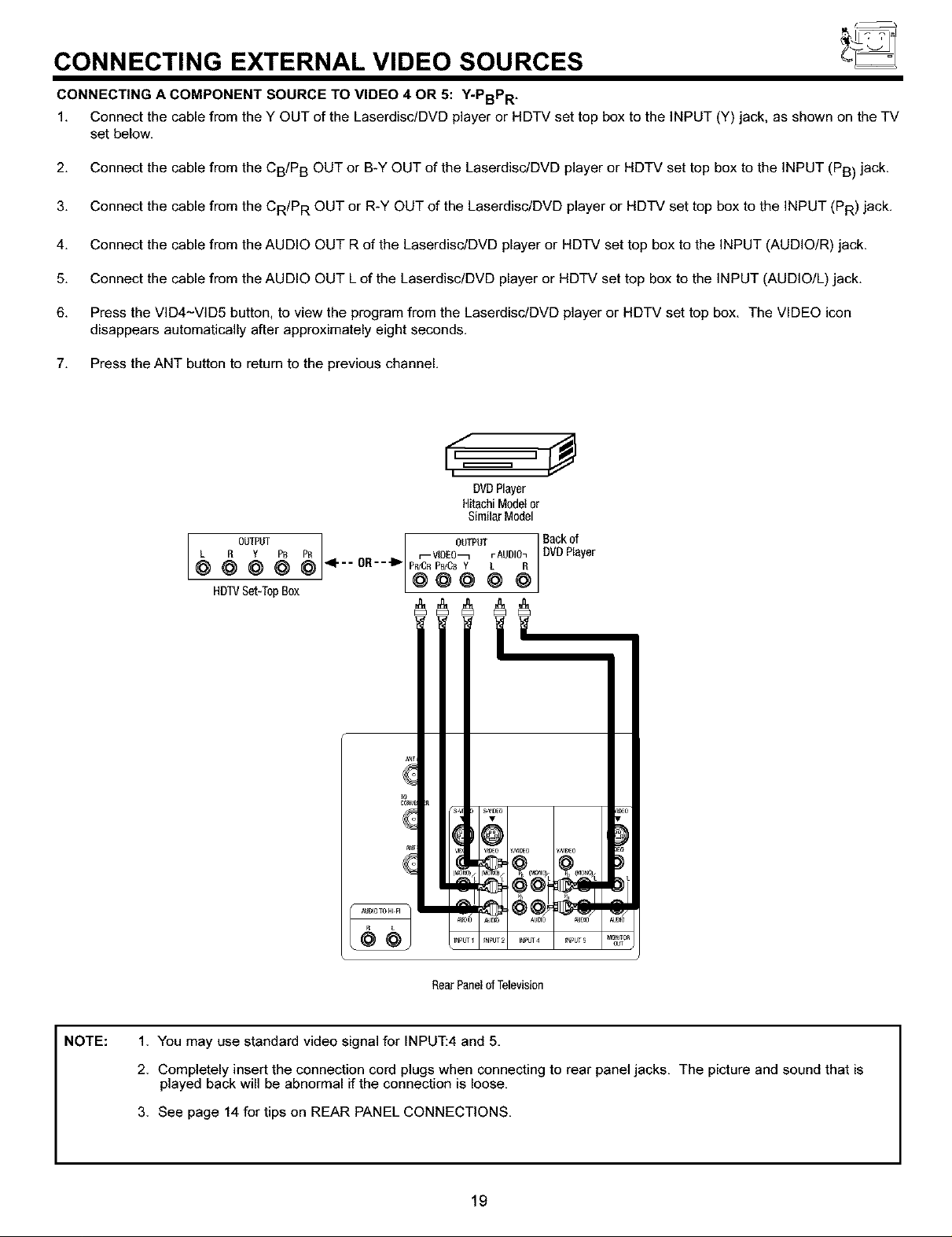
CONNECTING A COMPONENT SOURCE TO VIDEO 4 OR 5: Y-PBPR .
1. Connect the cable from the Y OUT of the Laserdisc/DVD player or HDTV set top box to the INPUT (Y) jack, as shown on the TV
set below.
2. Connect the cable from the CB/P B OUT or B-Y OUT of the Laserdisc/DVD player or HDTV set top box to the INPUT (PB) jack.
3. Connect the cable from the CR/P R OUT or R-Y OUT of the Laserdisc/DVD player or HDTV set top box to the INPUT (PR) jack.
4. Connect the cable from the AUDIO OUT R of the Laserdisc/DVD player or HDTV set top box to the INPUT (AUDIO/R) jack.
5. Connect the cable from the AUDIO OUT Lof the Laserdisc/DVD player or HDTV set top box to the INPUT (AUDIO/L) jack.
6. Press the VID4-VID5 button, to view the program from the Laserdisc/DVD player or HDTV set top box. The VIDEO icon
disappears automatically after approximately eight seconds.
7. Press the ANT button to return to the previous channel.
DVDPlayer
HitachiModelor
SimilarModel
OUTPUT
L R Y PB PR
@ @ @ @ @ _I'--OR--"I_
HDTVSet-TopBox
OUT_m ] Backof
r--VlDEO_ rAUDIO_| DVDPlayer
NOTE:
s_E El
_OlO AUBp3 ' _J#}0
_JPUTI _NPUT; IN_u_4 _NPUT5
RearPanelof Television
_0_
1. You may use standard video signal for INPUT:4 and 5,
2. Completely insert the connection cord plugs when connecting to rear panel jacks. The picture and sound that is
played back will be abnormal if the connection is loose.
3. See page 14 for tips on REAR PANEL CONNECTIONS.
19
THE GENIUS REMOTE CONTROL
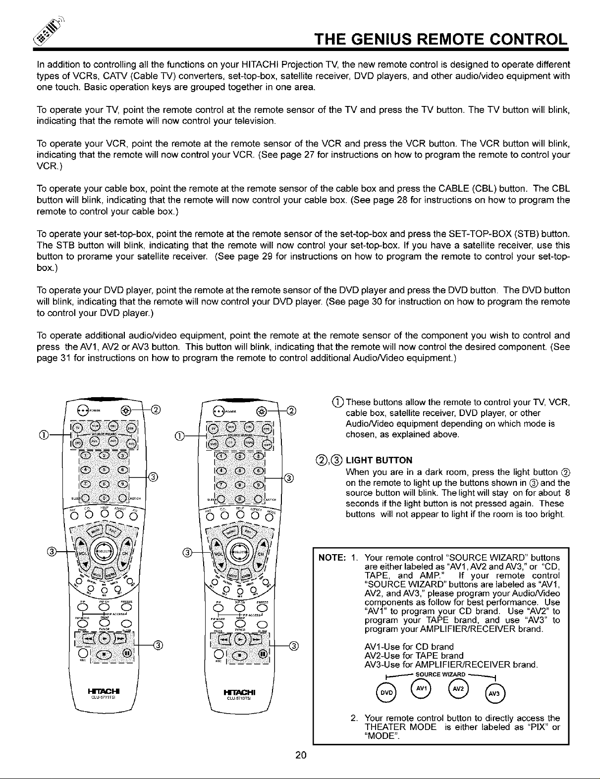
In addition to controlling all the functions on your HITACHI Projection TV, the new remote control is designed to operate different
types of VCRs, CATV (Cable TV) converters, set-top-box, satellite receiver, DVD players, and other audio/video equipment with
one touch. Basic operation keys are grouped together in one area.
To operate your TV, point the remote control at the remote sensor of the TV and press the TV button. The TV button will blink,
indicatingthat the remote will now control your television.
To operate your VCR, point the remote at the remote sensor of the VCR and press the VCR button. The VCR button will blink,
indicatingthat the remote will now control your VCR. (See page 27 for instructions on how to program the remote to control your
VCR)
Tooperate your cable box, point the remote at the remote sensor of the cable box and press the CABLE (CBL) button. The CBL
button will blink, indicating that the remote will now control your cable box. (See page 28 for instructions on how to program the
remote to control your cable box.)
Tooperate your set-top-box, point the remote at the remote sensor of the set-top-box and press the SET-TOP-BOX (STB) button.
The STB button will blink, indicatingthat the remote will now control your set-top-box. If you have a satellite receiver, use this
button to prorame your satellite receiver. (See page 29 for instructionson how to program the remote to control your set-top-
box.)
Tooperate your DVD player, point the remote at the remote sensor of the DVD player and press the DVD button. The DVD button
will blink, indicatingthat the remote will now control your DVD player. (See page 30 for instruction on how to program the remote
to control your DVD player.)
To operate additional audio/video equipment, point the remote at the remote sensor of the component you wish to control and
press the AV1, AV2 orAV3 button. This button will blink, indicating that the remote will now control the desired component. (See
page 31 for instructionson how to program the remote to control additional AudioNideo equipment.)
(_) These buttons allow the remote to control your TV, VCR,
cable box, satellite receiver, DVD player, or other
AudioNideo equipment depending on which mode is
chosen, as explained above.
@,®
LIGHT BUTTON
When you are in a dark room, press the light button (_
on the remote to light up the buttons shown in 0 and the
source button will blink. The light will stay on for about 8
seconds if the light button is not pressed again. These
buttons will not appear to light if the room is too bright.
NOTE: 1. Your remote control "SOURCE WIZARD" buttons
are either labeled as "AV1, AV2 and AV3," or "CD,
TAPE, and AMP." If your remote control
"SOURCE WIZARD" buttons are labeled as "AV1,
AV2, and AV3," please program your AudioNideo
components as follow for best performance. Use
"AVI" to program your CD brand. Use "AV2" to
program your TAPE brand, and use "AV3" to
program your AMPLIFIER/RECEIVER brand.
AV1-Use for CD brand
@-
0 O O
_PiP_cas_J
-@
.®
o
-@
AV2-Use for TAPEbrand
AV3-Use for AMPLIFIER/RECEIVER brand.
I'i'llACl-II
2O
2. Your remote control button to directly access the
THEATER MODE is either labeled as "PIX" or
"MODE".
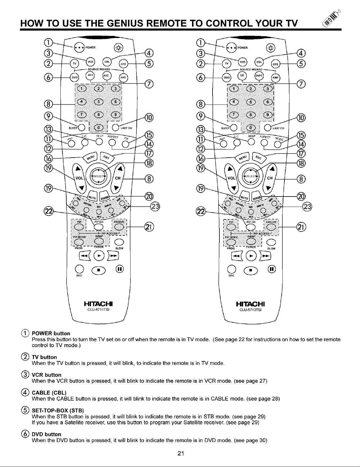
HOW TO USE THE GENIUS REMOTE TO CONTROL YOUR TV
REC
HITACHI
C_LU-5711 TSI
(_) POWER button
Press this button to turn the TV set on or off when the remote is in TV mode. (See page 22 for instructions on how to set the remote
control to TV mode.
(_TV button
When the TV button is pressed, it will blink, to indicate the remote is in TV mode.
(_) VCR button
When the VCR button is pressed, it will blink to indicate the remote is in VCR mode. (see page 27)
(_ CABLE (CBL)
When the CABLE button is pressed, it will blink to indicate the remote is in CABLE mode. (see page 28)
(_) SET-TOP-BOX (STB)
When the STB button is pressed, it will blinkto indicate the remote is in STB mode. (see page 29)
If you have a Satellite receiver, use this button to program your Satellite receiver. (see page 29)
(_) DVD button
When the DVD button is pressed, it will blink to indicate the remote is in DVD mode. (see page 30)
®
R£C
HITACHI J
CLU-5713TSl
®
21
 Loading...