

Hitachi 61SWX12B, 61SWX10B, 53SWX12B, 53SWX10B, 43UWX10B Owner’s Manual
',CTION COLOR TV
_TING GUIDE
IMPORTANT SAFETY INSTRUCTIONS
FIRST TIME USE
THE GENIUS
REMOTE CONTROL
ULTRATEC BIT-MAP
ON-SCREEN DISPLAY
2-4
5-22
23-35
36-70
,_,_ ASK
USEFUL INFORMATION INDEX 71-75
-_-RGYSTAR ® Partner, Hitachi, Ltd. has determined that this
_eets the ENERGYSTAR ® guidelines for energy efficiency.
Follow all warnings and instructions marked on this projection television.
IMPORTANT
WARNING
RISK OF ELECTRIC SHOCK
DO NOT OPEN
CAUTION: TO REDUCE THE RISK OF ELECTRIC SHOCK,
DO NOT REMOVE COVER (OR BACK).
NO USER SERVICEABLE PARTS INSIDE.
REFER SERVICING TO QUALIFIED SERVICE PERSONNEL.
WARNING:
TO REDUCE THE RISK OF FIRE OR ELECTRIC SHOCK, DO NOT
EXPOSE THIS APPARATUS TO RAIN OR MOISTURE.
NOTE: • There are no user serviceable parts inside the television.
• Model and serial numbers are indicated on back side of the television.
• This television is not intended for use in a computer room.
CAUTION: Adjust only those controls that are covered in the instructions, as improper changes or modifications not
expressly approved by HITACHI could void the user's warranty.
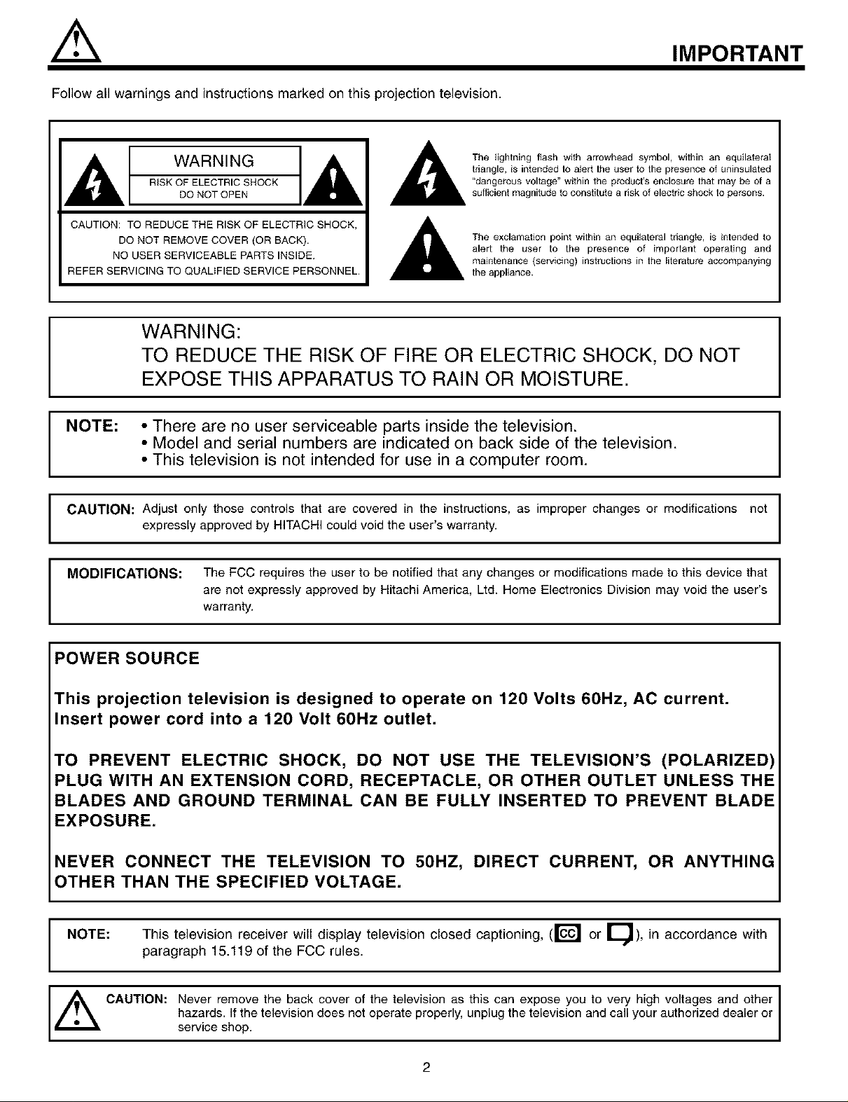
The lightning flash with arrowhead symbol, within an equilateral
triangle, is intended to alert the user to the presence of uninsulated
"dangerous voltage" within the products enclosure lhat may be of a
sufficient magnitude to constitute a risk of electric shock 1o persons.
The exclamation point within an equilateral triangle, is intended to
alert the user to the presence of imporlant operating and
maintenance (servicing) instruclions in lhe lilerature accompanying
the appliance.
I
I
I
MODIFICATIONS: The FCC requires the user to be notified that any changes or modifications made to this device that
are not expressly approved by Hitachi America, Ltd. Home Electronics Division may void the user's
warranty.
POWER SOURCE
This projection television is designed to operate on 120 Volts 60Hz, AC current.
Insert power cord into a 120 Volt 60Hz outlet.
TO PREVENT ELECTRIC SHOCK, DO NOT USE THE TELEVISION'S (POLARIZED)
PLUG WITH AN EXTENSION CORD, RECEPTACLE, OR OTHER OUTLET UNLESS THE
BLADES AND GROUND TERMINAL CAN BE FULLY INSERTED TO PREVENT BLADE
EXPOSURE.
NEVER CONNECT THE TELEVISION TO 50HZ, DIRECT CURRENT, OR ANYTHIN(
OTHER THAN THE SPECIFIED VOLTAGE.
NOTE:
This television receiver will display television closed captioning, (r_ or E_), in accordance with I
paragraph 15.119 of the FCC rules.
I
I
_ CAUTION: Never remove the back cover of the television as this can expose you to very high voltages and other
servicehazards'shop,f the te ev s on does not operate proper y, unp ug the te ev s on and ca your author zed dea er or
2
SAFETY TIPS
IMPORTANT SAFETY INSTRUCTIONS
CAUTION: • Read these instructions.
• Keep these instructions.
SAFETY POINTS YOU SHOULD KNOW ABOUT
YOUR HITACHI PROJECTION TELEVISION
• Heed all warnings.
• Follow ait instructions.
Our reputation has been built on the quality, performance, and ease of service of HITACHI televisions.
Safety is also foremost in our minds in the design of these units. To help you operate these products properly, this section illustrates safety tips which
will be of benefit to you. Please read it carefully and apply the knowledge you obtain from it to the proper operation of your HITACHI television.
Please fill out your warranty card and mail it to HITACHI. This will enable HITACHI to notify you promptly in the improbable event that a safety
problem should be discovered in your product model.
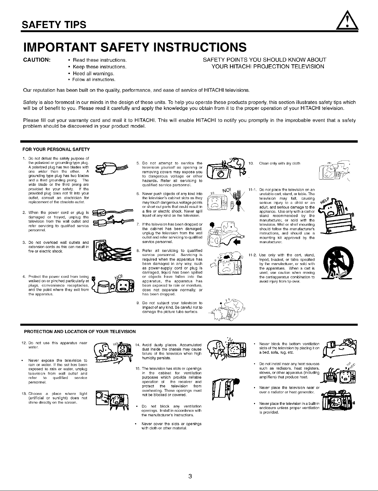
FORYOURPERSONALSAFETY
1 Do not defeat the safety purpose of
tile pa[adzed or grounding type plug
A polarized plug has _o blades with
one wider than the othe_ A
grounding type plug has two blades
and a third grounding prong¸ The
wide blage or the _ird prong are
provided for your safety¸ If the
prowded plug does not fit into your
outlet, consult an eJectriclan for
replacement of the obsoJete outlet¸
2 When the power cord or plug is
damaged or frayed, unplug the
television from the wall outlet and
refer servicing to qualified service
personnel¸
3 DO not overload walt outlets and
extension cords as this can resuJt in
fire or electric shock¸
4 Protect the power cord from being O_-
walked on or pinched particularly at
plugs, convenience receptacles,
and the point where they exit from
the apparatus
5 DO not attempt to service the
teJevision yourself as opening or
removing covers may expose you
to dangerous voltage or other
hazards. Refer all servicing to
qualified service personnel
6.
Never push objects of any kind into
the television's cabinet slots as they
may touch dangerous voltage points
or short out parts that could result in
a fire or electric shock Never spill
liquid of any kind on the television
ifthe television has been dropped or
the cabinet has been damaged,
unplug the television from the wall
outlet and refer servicing to qualified
service personnel
Refer all servicing to qualified
service personnel Servicing [s
required when the apparatus has
been damaged [n any way, such
as power supaty cord or plug [s
damaged, liquid has been ag[lled
or objects have fallen into the
apparatus, the apparatus has
been exposed to rain or moisture,
does not ooparate normalty, or
has been dropped
g.
Do not subject your television to
impact of any kind Be careful not to
damage the picture tube surface
Clean only with dry cloth
11 1 Do not place the television on an
unstable cart, stand, or table The
television may fall, causing
serious lniury to a child or an
adult, and serious damage to the
appliance Use only with a cart or
stand recommended by the
manufacturer, or sold with the
television¸ Wall or shelf moun_Jng
should follow the manufacturer's
instructions, and should use a
mounting kit approved by the
manulacturer
11 2 Use only with the cart, stand,
tripod, bracket, or table specified
by the manufacturer, or sold with
the agparatues When a cart [s
used, use caution when moving
the cart/apparatus combination to
avoid iniury from tip over
PROTECTION AND LOCATION OF YOUR TELEVISION
12 Do not use this apparatus near
water
• Never expose the television to
rain or water If the set has been
exposed to rain or water, unplug
television from wail outlet and
refer to qualified service
personnel¸
13 Choose a place where light
(artificial or sunlight) does not
shine directly on the screen
14 Avoid dusty places Accumulated _" _.e?_-.j$_¥'_j
dust inside the chassis may cause
failure of the television when high
humidity persists
15 The television has slots or openings
[n the cabinet for ventilation
purposes which provide reliable
operation ol the receiver and
protect the television from
overheating These openings must
not be bJocked or covered¸
• Do not block any ventilation
openings Installin accordance with
the manufacturer's instructions
• Never cover the slots or openings
with cloth or other material
3
Never block the bottom ventilation rJ[_
slots of the television by placing [ton
a bed, sofa, rug, etc
• Do not install near any heat sources ,,u%,_,
such as radiators, heat registers, _ _j'_
stoves, or other apparatus (including f_,_'_'_'_
amplifiers) that produce heat¸
• Never place the television near or
over a radiator or heat generator¸
• Never place the television in a built in l_l|
encJosure unless proper ventilation
is provided¸
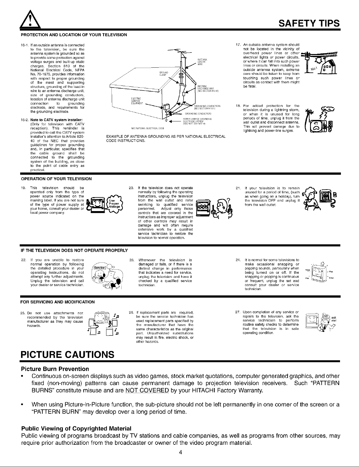
PROTECTION AND LOCATION OF YOUR TELEVISION
16 1 If an outside antenna is connected
to the tetevision, be sure the
antenna system ls grounded so as
to provide some protection against
voltage surges and buildup static
charges¸ Section 810 of the
National Electrical Code, NFPA
No 70 1975, provides information
with respect to proper grounding
of the mast and supporting
structure, grounding of the lead-in
wire to an antenna discharge unit,
size of grounding conductors,
IDeation of antenna discharge unit
connection to grounding
electrode, and requirements for
the grounding eJectrode
16 2. Note to CATV system installer;
(Only for television with CATV
reception) This reminder ls
provided to call the CATV system
[nstafler's attention to Ar tlcle 820
40 of the NEC that provides
guidelines for proper grounding
and, [n particular, specifies that
the cable ground shall be
connected to the grounding
system of the building, as ctose
to the point of cable entry as
practical
EXAMPLE OF ANTENNA GROUNDING AS PER NATIONAL ELECTRICAL
CODE iNSTRUCTIONS
OPERATION OF YOUR TELEVISION
19 This television should be
operated only from the type of
power source indicated on the
marking [abel If you are not sure
of the type of power supply at
your home, consult you_ dealer or
local power company¸
20 If the telewsion does not operate
normally by following the opera_ng
instructions, unplug the television
from the waft outlet and refer
servicing to qualified service
personnel Adjust only those
controls that are covered in the
instructions as improper adjustment
of other controls may result in
damage and will often require
extensive work by a qualified
service technlciaJ_ to restore the
television to normal operation
SAFETY TIPS
17
An outside antenna system should
not be located in the vicinity of
overhead power lines or other_
electrical tights or power circuits,
or where it can fail into such power
lines o_ circuits When installing an
outside antenna system, extreme
care should be taken to keep from
touching such power fines or
circuits as contact with them might
be fatal
18
For added protection for the
television dunng a lightning stom_,
or when it is unused for long
periods of time, unplug it from the
wa_ out_et and disconnect antenna
This will prevent damage due to
lightning and power line surges¸
21 if your television is to remain
unused for a period of _me, (such j
as whel_goh_gonaholiday),tum _ _
the teJevision OFF and unplug it
from the wal_ outlet _/_1 _'_
IF THE TELEVISION DOES NOT OPERATE PROPERLY
22 if you are unable to restore
normal operation by foflow[ng
the detailed procedure in your
operating instructions, do not
attempt any further adjustments
Unplug the television and call
you_ deale_ or service technician¸
23 Whenever the television [s
damaged or fails, or if there is a
distinct change in pe#ormaRce
that indicates a need for service,
unpEug the television and have it
checked by a qualified service
technician¸
24 it is normal for some teEevisions to
make occasional snapping or -_+
popping sounds, par tlcuEady when _+
being turned on or off If the
snapping or popping is continuous _.+p
or frequent, unplug the set and
consult your dea_er or service
technician
FOR SERVICING AND MODIFICATION
27
25 Do not use attachments not
recommended by the television
manufacturer as they may cause
hazards
26 If replacement parts are required,
be sure the service technician has
used replacement parts specified by
the manufacturer that have the
same characteristics as +J_eoriginal
part Unauthorized substitutions
may result iR fire, electric shock, or
other hazards
Upon completion of any service or
repairs to the television, ask the
service technician to perform
rou_ne safety checks to determine
that the television is in safe
operating condition¸
PICTURE CAUTIONS
Picture Burn Prevention
• Continuous on-screen displays such as video games, stock market quotations, computer generated graphics, and other
fixed (non-moving) patterns can cause permanent damage to projection television receivers. Such "PATTERN
BURNS" constitute misuse and are NOT COVERED by your HITACHI Factory Warranty.
• When using Picture-in-Picture function, the sub-picture should not be left permanently in one corner of the screen or a
"PATTERN BURN" may develop over a long period of time.
Public Viewing of Copyrighted Material
Public viewing of programs broadcast by TV stations and cable companies, as well as programs from other sources, may
require prior authorization from the broadcaster or owner of the video program material.
4
ACCESSORIES
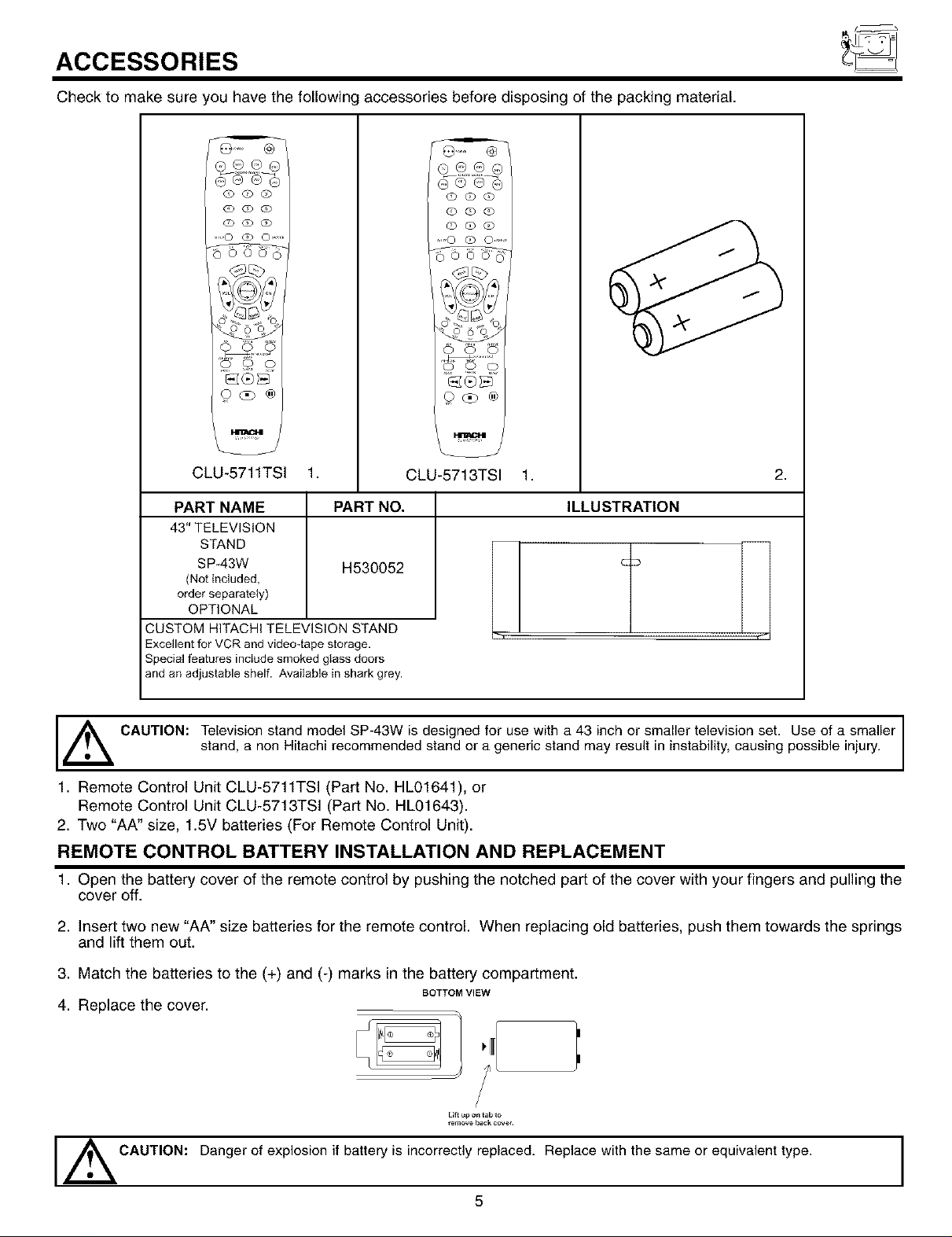
Check to make sure you have the following accessories before disposing of the packing material.
O(D#O
QQOD
(OC) O)
.....O'(QO .......
0 0 0
o
CLU-5711TSI 1.
PART NAME
43" TELEVISION
STAND
SP-43W
(Notincluded,
orderseparately)
OPTIONAL
CUSTOM HITACHI TELEVISION STAND
Excellent for VCR and video4ape storage.
Special features include smoked glass doors
and an adjustable shelf. Available in shark grey.
PART NO,
H530052
(D(DQ
(D C) (b
(o q) qo
....0 (o 0 ......
_®_
0_o®
CLU-5713TSI 1.
2,
ILLUSTRATION
,_ CAUTION: Television stand model SP-43W is designed for use with a 43 inch or smaller television set. Use of a smaller
stand, a non Hitachi recommended stand or a generic stand may result in instability, causing possible injury.
1. Remote Control Unit CLU-5711TSI (Part No. HL01641), or
Remote Control Unit CLU-5713TSI (Part No. HL01643).
2. Two "AA" size, 1.5V batteries (For Remote Control Unit).
REMOTE CONTROL BATTERY INSTALLATION AND REPLACEMENT
1. Open the battery cover of the remote control by pushing the notched part of the cover with your fingers and pulling the
cover off.
2. Insert two new "AA" size batteries for the remote control. When replacing old batteries, push them towards the springs
and lift them out.
3. Match the batteries to the (+) and (-) marks in the battery compartment.
BOTTOM VIEW
4. Replace the cover.
Lilt _p o_ tab to
_emove _a_k eeve_.
Danger of explosion if battery is incorrectly replaced. Replace with the same or equivalent type.
CAUTION:
5
I
HOW TO SET UP YOUR NEW HITACHI PROJECTION TV
ANTENNA
Unless your TV is connected to a cable TV system or to a centralized antenna system, a good outdoor color TV antenna is
recommended for best performance. However, if you are located in an exceptionally good signal area that is free from interference and
multiple image ghosts, an indoor antenna may be sufficient.
LOCATION
Select an area where sunlight or bright indoor illumination will not fall directly on the picture screen. Also, be sure that the location
selected allows a free flew of air to and from the perforated back cover of the set.
To avoid cabinet warping, cabinet color changes, and increased chance of set failure, do net place the TV where temperatures can
become excessively hot, for example, in direct sunlight or near a heating appliance, etc.
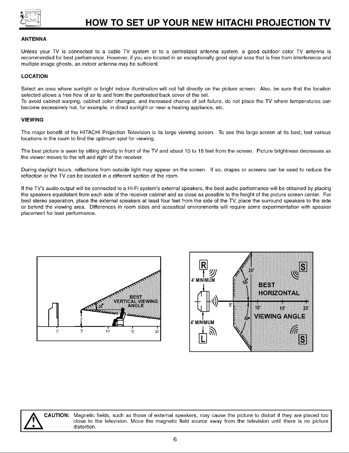
VIEWING
The major benefit of the HITACHI Projection Television is its large viewing screen. To see this large screen at its best, test various
locations in the room to find the optimum spot for viewing.
The best picture is seen by sitting directly in front of the TV and about 10 to 18 feet from the screen. Picture brightness decreases as
the viewer moves to the left and right of the receiver.
During daylight hours, reflections from outside light may appear on the screen. If so, drapes or screens can be used to reduce the
reflection or the TV can be located in a different section of the room.
If the TV's audio output will be connected to a Hi-Fi system's extemal speakers, the best audio performance will be obtained by placing
the speakers equidistant from each side of the receiver cabinet and as close as possible to the height of the picture screen center. For
best stereo separation, place the external speakers at least four feet from the side of the TV, place the surround speakers to the side
or behind the viewing area. Differences in room sizes and acoustical environments will require some experimentation with speaker
placement for best performance.
1
0'
,_ CAUTION: Magnetic fields, such as those of external speakers, may cause the picture to distort if they are placed tee
close to the television. Move the magnetic field source away from the television until there is no picture
distortion.
6
HOOK-UP CABLES AND CONNECTORS
Most video/audio connections between components can be made with shielded video and audio cables that have phono connectors.
For best performance, video cables should use 75-Ohm coaxial shielded wire. Cables can be purchased from most stores that sell
audio/video products. Below are illustrations and names of common connectors. Before purchasing any cables, be sure of the output
and input connector types required by the various components and the length of each cable.
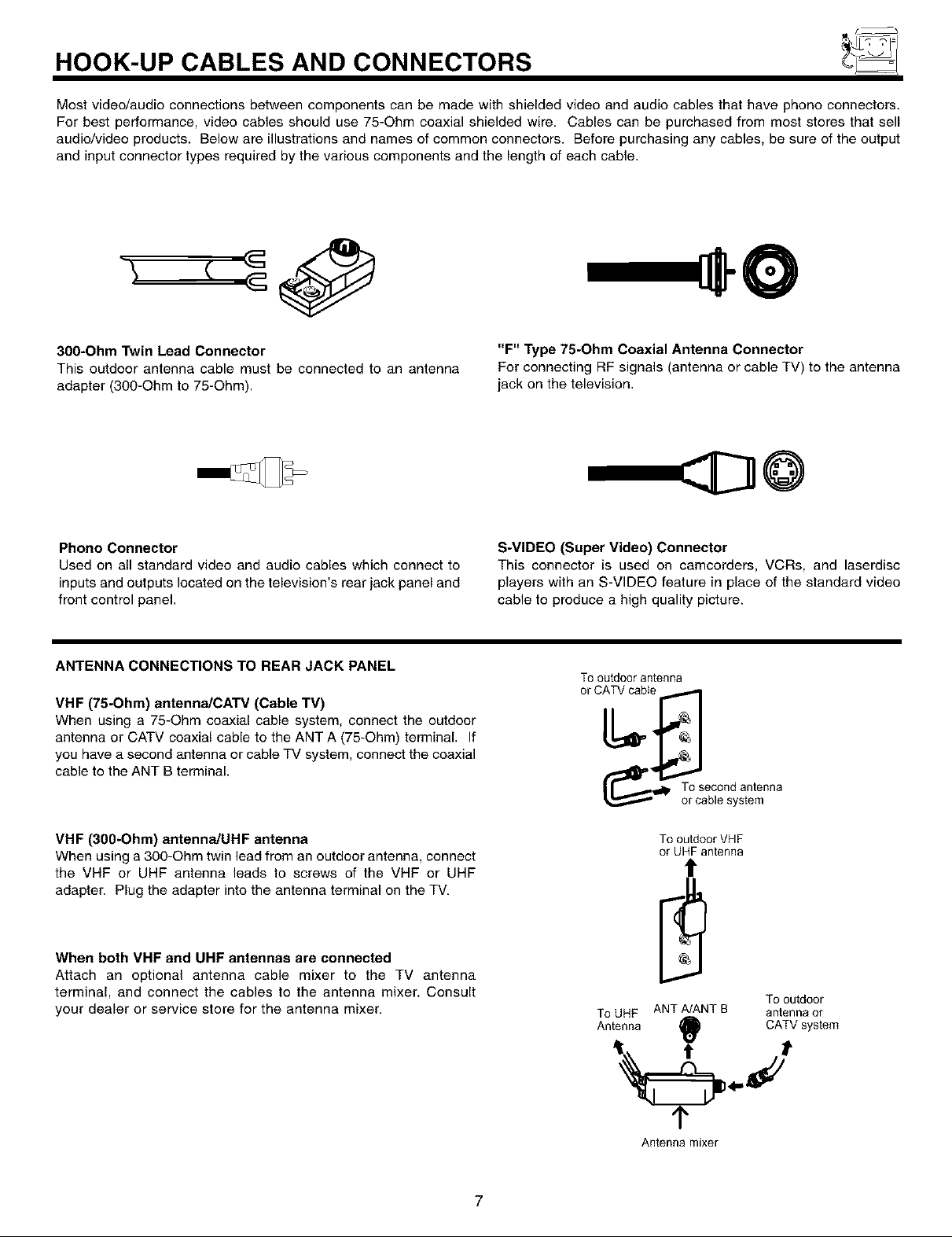
3O0-Ohm Twin Lead Connector
This outdoor antenna cable must be connected to an antenna
adapter (300-Ohm to 75-Ohm).
Phono Connector
Used on all standard video and audio cables which connect to
inputs and outputs located on the television's rear jack panel and
front control panel.
ANTENNA CONNECTIONS TO REAR JACK PANEL
VHF (75-Ohm) antenna/CATV (Cable TV)
When using a 75-Ohm coaxial cable system, connect the outdoor
antenna or CATV coaxial cable to the ANT A (75-Ohm) terminal. If
you have a second antenna or cable TV system, connect the coaxial
cable to the ANT B terminal.
"F" Type 75-Ohm Coaxial Antenna Connector
For connecting RF signals (antenna or cable TV) to the antenna
jack on the television.
@
S-VIDEO (Super Video) Connector
This connector is used on camcorders, VCRs, and laserdisc
players with an S-VIDEO feature in place of the standard video
cable to produce a high quality picture.
Tooutdoorantenna
r__l_. Tosecondantenna
or cablesystem
VHF (3O0-Ohm) antenna!UHF antenna
When using a 3gO-Ohm twin lead from an outdoor antenna, connect
the VHF or UHF antenna leads to screws of the VHF or UHF
adapter. Plug the adapter into the antenna terminal on the TV.
When both VHF and UHF antennas are connected
Attach an optional antenna cable mixer to the TV antenna
terminal, and connect the cables to the antenna mixer. Consult
your dealer or service store for the antenna mixer.
To outdoor VHF
or UHF antenna
t
Tooutdoor
ToUHF ANT A/ANTB antennaor
Antenna
, _ C'_ system
¢
Antenna mixer
7
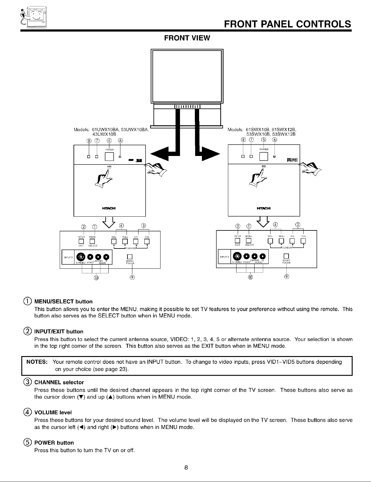
FRONT VIEW
IIIIIIIIII
FRONT PANEL CONTROLS
Models: 61UWX10BA, 53UWX10B, _
43UWX10B
Models: 61SWX10B, 61SWX12B,
53SWX10B, 53SWX12B
@0 ® ®
,!
_ [_
HITACHI
......oo i o%
..... T
® ®
(_) MENU/SELECT button
This button allows yeu te enter the MENU, making it possible to set TV features to your preference without using the remote. This
button also serves as the SELECT button when in MENU mode.
® ®
(_) INPUT/EXIT button
Press this button to select the current antenna source, VIDEO: 1, 2, 3, 4, 5 or alternate antenna source. Your selection is shown
in the top right corner of the screen. This button also serves as the EXIT button when in MENU mode.
NOTES: Your remote control does not have an INPUT button. To change to video inputs, press VIDI-VID5 buttons depending
on your choice (see page 23).
(_ CHANNEL selector
Press these buttons until the desired channel appears in the top right corner of the TV screen. These buttons also serve as
the cursor down (_') and up (A) buttons when in MENU mode.
(_ VOLUME level
Press these buttons for your desired sound level. The volume level will be displayed on the TV screen. These buttons also serve
as the cursor left (4) and right (>-) buttons when in MENU mode.
(_) POWER button
Press this button to turn the TV on or off.
8
FRONT PANEL CONTROLS
(_) POWER light
You will see a red light when the TV is turned on.
(_) PERFECT PICTURE sensor
The Perfect Picture sensor will make automatic picture adjustments depending on the amount of light in the room to give the best
picture. (see page 57)
(_ REMOTE CONTROL sensor
Point your remote at this area when selecting channels, adjusting volume, etc.
(_) MAGIC FOCUS
Use this button to adjust your picture quality to optimum performance.
(_) FRONT INPUT JACKS (for VIDEO: 3)
Use these audio/video jacks for a quick hook-up from a camcerder or VCR to instantly view your favorite show or new recording.
Press the INPUT button until VIDEO: 3 appears in the top right corner of the TV screen. If you have mene sound, insert the audio
cable into the left audio jack.
NOTES:
1. Your HITACHI Projection TV will appear to be turned OFF if there is no video input when VIDEO: 1, 2, 3, 4 or 5 is
selected. Check the Power Light to make sure the TV is turned off when net in use.
2. To see an auto-demonstration of the on-screen displays with HELP text displayed, press and hold the POWER
button on the TV set for approximately five seconds. Press the POWER button on the TV again to end the auto-
demonstration.
9
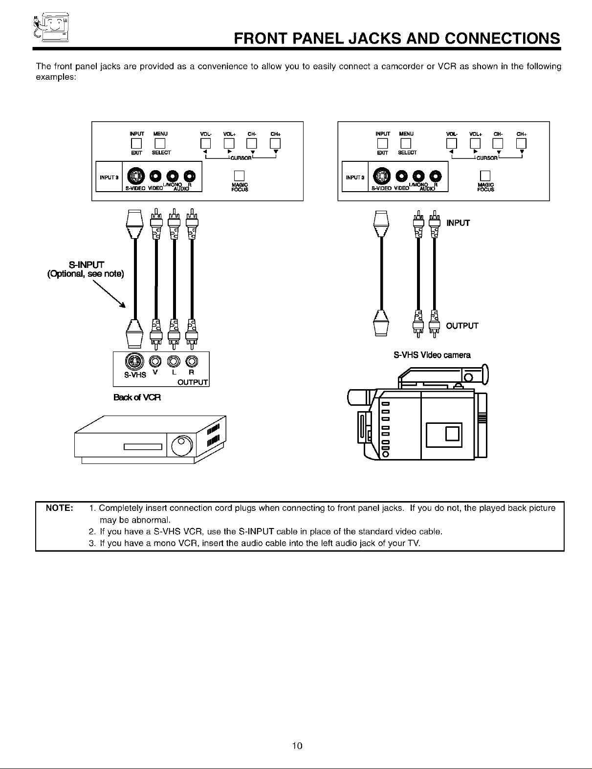
FRONT PANEL JACKS AND CONNECTIONS
The front panel jacks are provided as a convenience to allow you to easily connect a camcorder or VCR as shown in the following
examples:
S-INPUT
(Optional, see note)
Backot VCR
INPUT MENU
[] []
EgQT SELE,_r
OO
VOL- VOI.+ CH- CH+
D D D D
I ,%_o.-, T
]o
_ic
_IC_
INPUT MENU VOI.- VOI.+ CH- CH+
D D D D D D
_,r_,ELE_ " 'OU_." "
I,.-,10o o] []
IllNPUT
OUTPUT
@ _) _Lou_ P S-VHS Video camera
S-VHS V UT
FOCUS
J,
NOTE: 1. Completely insert connection cord plugs when connecting to front panel jacks. If you do not, the played back picture
may be abnormal.
2. If you have a S-VHS VCR, use the S-INPUT cable in place of the standard video cable.
3. If you have a mono VCR, insert the audio cable into the left audio jack of your TV.
10
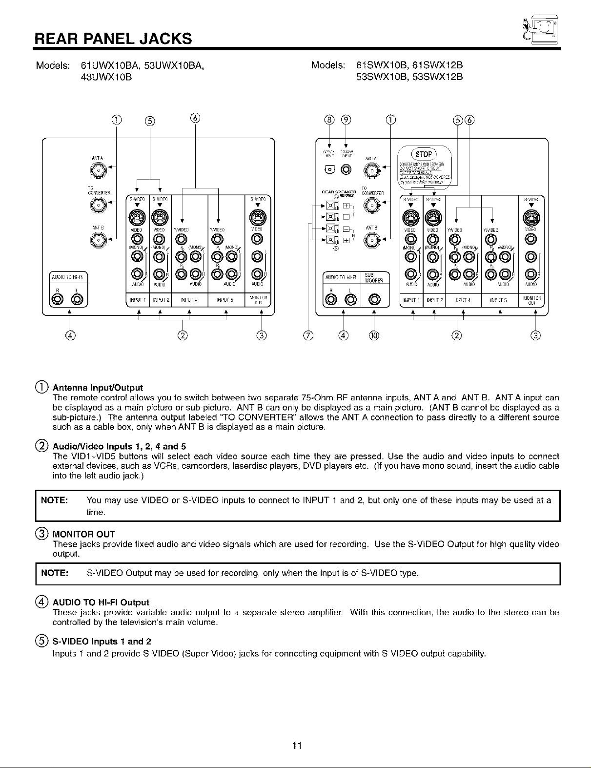
REAR PANEL JACKS
Models: 61UWX10BA, 53UWX10BA,
43UWX10B
@ ® ®
ANTA
ANT B
SVDE1
Y/VIDEO_ YIVIOEO
AUBIO AgBO AUglO
I INPUT2 INPUT4 JNPU[5
T@ f t t t .
SVIDEO
!
oo.
OIJT
Models: 61SWX10B, 61SWX12B
53SWX10B, 53SWX12B
NP[_
ANTA
@@
.... _ CO_VERTEn
÷[_ _ 0 ÷
_ _1 ANrB
TO
®
f t t t
S VI,_EO•
y/VIDEO VOEO
NPUT4 INPUT5 MO_I_TO£
(_) Antenna Input/Output
The remote control allows you to switch between two separate 75-Ohm RF antenna inputs, ANT A and ANT B. ANT A input can
be displayed as a main picture or sub-picture. ANT B can only be displayed as a main picture. (ANT B cannot be displayed as a
sub-picture.) The antenna output labeled "TO CONVERTER" allows the ANT A connection to pass directly to a different source
such as a cable box, only when ANT B is displayed as a main picture.
Audio/Video Inputs 1, 2, 4 and 5
The VIDI-VID5 buttons will select each video source each time they are pressed. Use the audio and video inputs to connect
external devices, such as VCRs, camcorders, laserdisc players, DVD players etc. (If you have mono sound, insert the audio cable
into the left audio jack.)
NOTE: You may use VIDEO or S-VIDEO inputs to connect to INPUT 1 and 2, but only one of these inputs may be used at a I
time.
MONITOR OUT
These jacks provide fixed audio and video signals which are used for recording. Use the S-VIDEO Output for high quality video
output.
I NOTE: S-VIDEO Output may be used for recording, only when the input is of S-VIDEO type. I
(_ AUDIO TO HI-FI Output
These jacks provide variable audio output to a separate stereo amplifier. With this connection, the audio to the stereo can be
controlled by the television's main volume.
(_) S-VIDEO Inputs 1 and 2
Inputs 1 and 2 provide S-VIDEO (Super Video) jacks for connecting equipment with S-VIDEO output capability.
I
I
I
11
REAR PANEL JACKS
(_) Component: Y-PBPR Inputs
Inputs 4 and 5 provide Y-PBPR jacks for connecting equipment with this capability, such as a DVD player or Set Top Box. You may
use standard video signal for INPUT:4 and 5.
Items (_ - (_ are for 53/61SWX10B and 53/61SWX12B only.
(_) REAR SPEAKER Output Terminals
These terminals are used to connect external speakers, which are used for the surround sound feature. The volume level is
controlled by the television's main volume. These speaker output terminals can be turned on and off in the THEATER-SPEAKER
SETUP menu. Use speakers with 8-Ohm impedance only.
(_ Optical Input
This jack provides high quality audio input from a Dolby Digital DVD player or HDTV Set Top Box. Use a digital optical cable to
connect your TV to a compatible device. This input can be used for VIDEO: 4 or VIDEO: 5 audio, as selected in the THEATER-
INPUT SOURCE menu. (see page 68)
(_) Coaxial Input
This jack provides high quality audio input from a Dolby Digital DVD player or HDTV Set Top Box. This input can be used for
VIDEO: 4 or VIDEO: 5 audio, as selected in the THEATER-INPUT SOURCE menu. (see page 68)
(_) SUB WOOFER Output
This jack provides variable audio output to a sub-woofer accessory. With this connection, the audio can be controlled by the
television's main volume. This feature can be turned on and off in the THEATER-SPEAKER SETUP menu.
NOTES:
1. DO NOT connect standard VIDEO and S-VIDEO to Input 1, 2 or 3 at the same time. S-Video has a higher priority over video input.
2. When using the Y-PBPR input jacks, connect your components audio output to the TV's Input 4 or 5 Left and Right Audio input jacks.
If your component has a Coaxial Out or Optical Out, use these connectors in place of the standard Audio L/R output jacks.
3. Your component outputs may be labeled Y, B-Y, and R-Y. In this case, connect the components B-Y output to the TV's PB input and
the components R-Y output to the TV's PR input.
4. Your component outputs may be labeled Y-CBC R. In this case, connect the component CB output to the TV's PB input and the
component CR output to the TV's PR input.
5. It may be necessary to adjust TINT to obtain optimum picture quality when using the Y-PBPR inputs. (See page 56)
6. To ensure no copyright infringement, the MONITOR OUT output will be abnormal, when using the Y-PBPR jacks.
7. This TV's optical digital input jack fully complies with the international standard governing this type of jack (IEC958), and is designed
for connection to a Dolby Digital (AC-3 or PCM) DVD Player or Dolby Digital (AC-3 or PCM) HDTV Set Top Box. Older equipment,
some of which is not fully compliant with IEC958, may not be compatible with the Dolby Digital bitstream. Such a connection using
anything other than Dolby Digital AC-3 or PCM bitstream could create a high noise level, causing damage to your speakers.
12
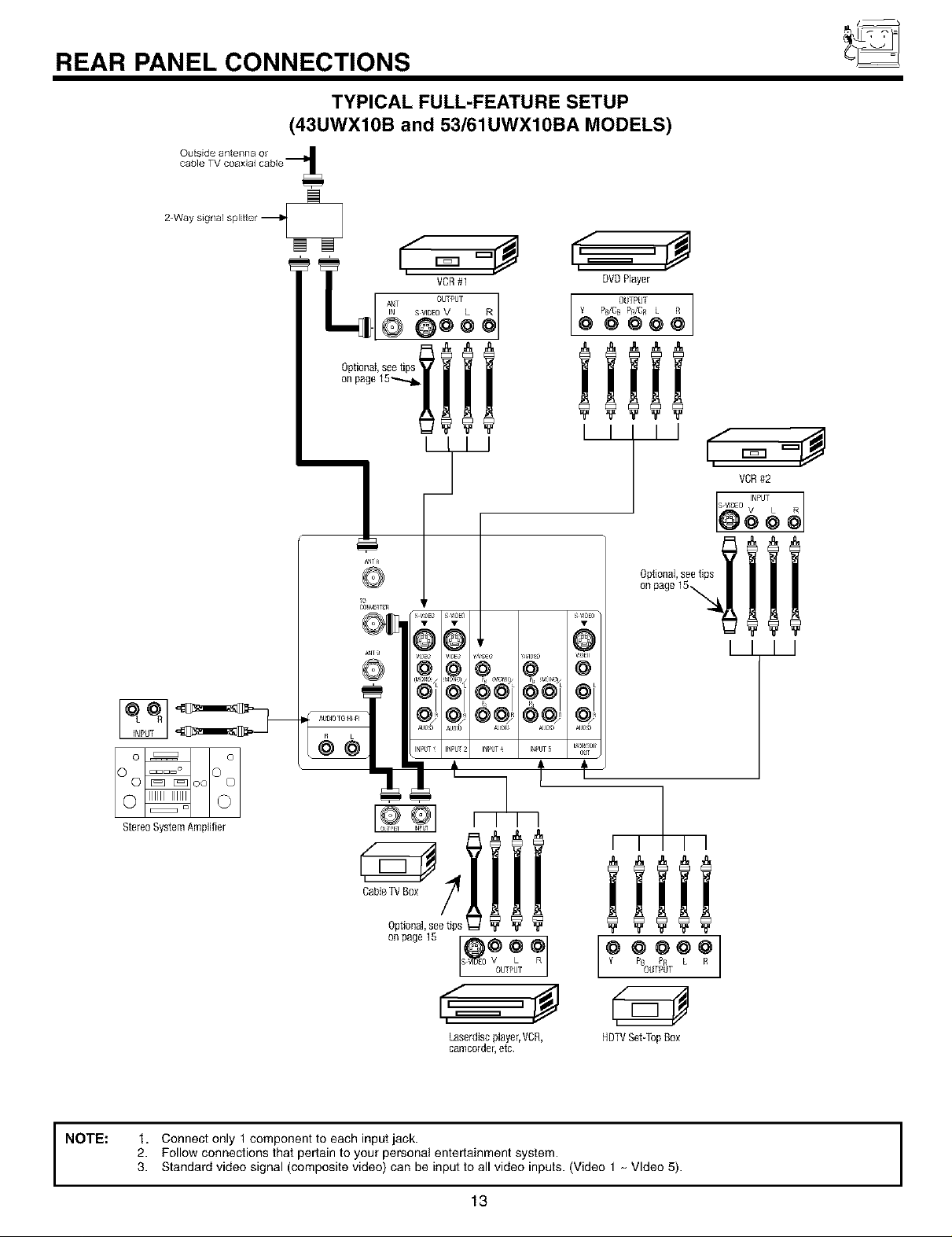
REAR PANEL CONNECTIONS
TYPICAL FULL-FEATURE SETUP
(43UWX10B and 53/61UWX10BA MODELS)
DVDPlayer
Ps/CB P_/CR L
OUTPUT
@@@
iiiii
I I I I I
Stereo System Amplifier
CableTVBox
Optional,seetips
F m
[s o
Optional,see
on page15,
I I I I
iiiii
P8 PR L
ooo?
OUTPUT
NOTE:
I
Laserdisc player,VCR,
camcordel, etc
1. Connect only 1 component to each input jack.
2. Follow connections that pertain to your personal entertainment system.
3. Standard video signal (composite video) can be input to all video inputs. (Video 1 _ Video 5).
13
HDTVSet-TopBox
I
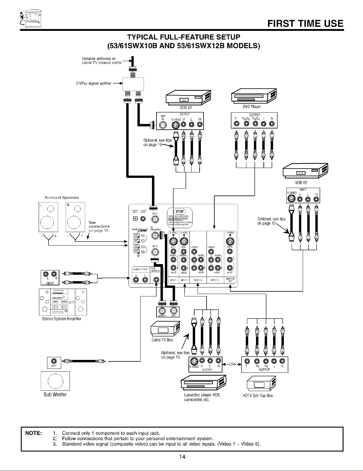
TYPICAL FULL-FEATURE SETUP
(53/61SWX10B AND 53/61SWX12B MODELS)
FIRST TIME USE
Surround Speakers
-y+
L[ =
_NT S V OEOOv_JT L 0]
© @oo
®@
II,
VCR#1
k_l I I
s VlOE0• s _
DVOPlayer
Y P_CB PR/CR L R
OUTPUT ]
@ @ @@@
i!iii
[ I 11
Optional, see tips
on page 15%
\
L_ m
Stereo System Amplifier
Cable[_/Box
SubWoofer Laserdisc player,VCR, HDTVSet-[bp Box
NOTE: 1. Connect only 1 component to each input jack.
2. Followconnections that pertain to your personal entertainment system.
3. Standard video signal (composite video) can be input to all video inputs. (Video 1 _ Video 5).
• * t
Optional,see tips
on page 15
14
F m
J
ca_]lcolder, etc.
I I I I
iiiii

REAR SPEAKER TERMINAL CONNECTIONS
CONNECT AFTER TURNING THE POWER TO THE TV OFF,
(Rear speaker connection applies to SWX model only)
Press the Right Speaker red button and insert the positive (+) lead wire into the hole next to the button. Once the wire is
in place, pull the red button back to original position and the wire is locked into place. In the same manner, press the
Right Speaker black button and insert the negative (-) lead wire. Repeat this procedure for the Left Speaker.
,_ CAUTION: Do not short speaker terminal, (do not connect a wire directly across any two terminals). This could cause I
damage to your audio outputs or other damage to your TV.
REAR SPEAKER
TO
EXTERNAL_
SPEAKER
®
®
I
I
,_ CAUTION: Do not connect speakers simultaneously to the REAR SPEAKER terminal of the Projection TV and an external
amplifier. This could damage both the TV and the speakers. Your TV was designed to use 8-Ohm speakers
only. Any other type may degrade the audio performance of your entertainment system.
Proiection T.V. Speaker Amplifier
TIPS ON REAR PANEL CONNECTIONS
-S-VIDEO connections are provided for high performance laserdisc players, VCRs etc. that have this feature. Use these connections
in place of the standard video connection if your device has this feature.
If your device has only one audio output (mono sound), connect it to the left audio jack on the television.
Refer to the operating guide of your other electronic equipment for additional information on connecting your hook-up cables.
A single VCR can be used for VCR #1 and VCR #2, but note that a VCR cannot record its own video or line output (INPUT: 1 in the
example on page 13 or 14). Refer to your VCR operating guide for more information on line input-output connections.
You may use VIDEO or S-VIDEO inputs to connect to Input 1 or Input 2, but only one of these may be used at a time.
Connect only 1 component (VCR, DVD player, camcorder, etc.) to each input jack.
COMPONENT: Y-PBPR (Input 4 &5) connections are provided for high performance components, such as DVD players and set-
top-boxes. Use these connections in place of the standard video connection if your device has this feature.
Your component outputs may be labeled Y, B-Y, and R-Y. In this case, connect the components B-Y output to the TV's PB input
and the components R-Y output to the TV's PR input.
Your component outputs may be labeled Y-CBC R. In this case, connect the components CB output to the TV's PB input and the
components CR output to the TV's PR input.
You may use standard video signal for INPUT:4 and 5.
It may be necessary to adjust TINT to obtain optimum picture quality when using the Y-PBPR inputs. (See page 56)
To ensure no copyright infringement, the MONITOR OUT output will be abnormal, when using the Y-PBPR jacks.
15
f_
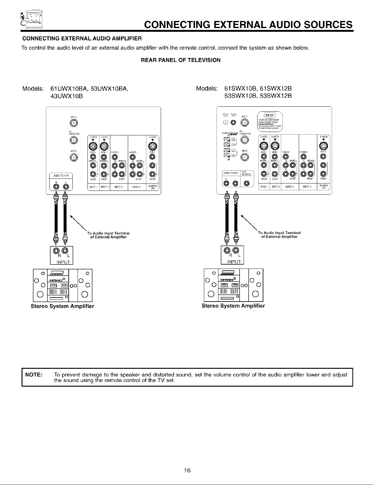
_ CONNECTING EXTERNAL AUDIO SOURCES
CONNECTING EXTERNAL AUDIO AMPLIFIER
To control the audio level of an external audio amplifier with the remote control, connect the system as shown below.
REAR PANEL OF TELEVISION
Models: 61UWX10BA, 53UWX10BA,
43UWX10B
To
s qaE0 s _laE8
66
_NPUT4 I_PUT_ _at_l_On
To Audio Input Terminal
of External Anlplifier
s v_E0
@
4a
OUT
Models: 61SWX10B, 61SWX12B
53SWX10B, 53SWX12B
o 9
To Audio Input Terminal
of External Amplifier
0u_
Oo ooOo
o_ o
Stereo System Amplifier
NOTE: To prevent damage to the speaker and distorted sound, set the volume control of the audio amplifier lower and adjust
the sound using the remote control of the TV set.
Oo ooOo
o_ o
Stereo System Amplifier
16
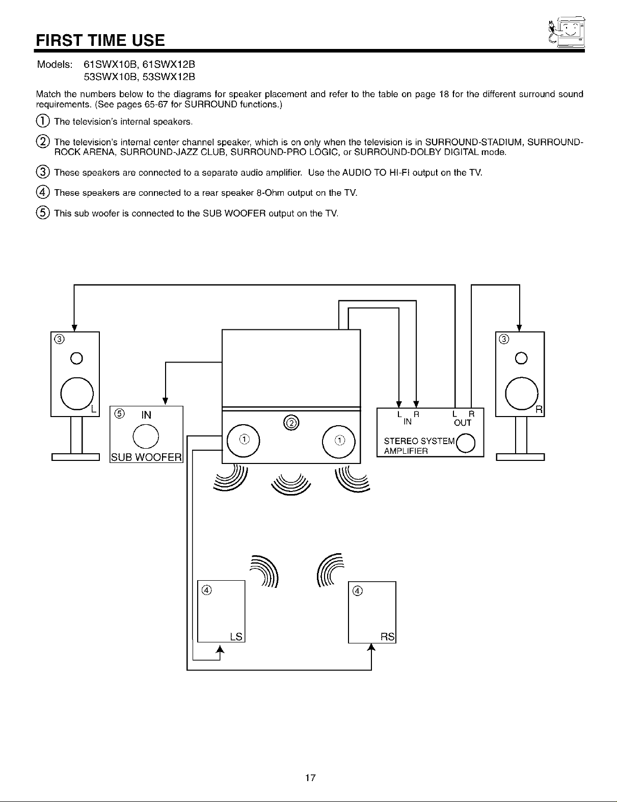
FIRST TIME USE
Models: 61SWX10B, 61SWX12B
53SWX10B, 53SWX12B
Match the numbers below to the diagrams for speaker placement and refer to the table on page 18 for the different surround sound
requirements. (See pages 65-67 for SURROUND functions.)
(_The television's internal speakers.
The television's internal center channel speaker, which is on only when the television is in SURROUND-STADIUM, SURROUND-
ROCK ARENA, SURROUND-JAZZ CLUB, SURROUND-PRO LOGIC, or SURROUND-DOLBY DIGITAL mode.
(_ These speakers are connected to a separate audio amplifier. Use the AUDIO TO HI-FI output on the TV.
(_ These speakers are connected to a rear speaker 8-Ohm output on the TV.
(_ This sub woofer is connected to the SUB WOOFER output on the TV.
O
©
UB WOOFER
© ©
®
y 'r
STEREO SYSTEM ['_
l LINR L R
AMPLIFIER
®
®
©
OUT
LS
17

FIRST TIME USE
Models: 61SWX10B,61SWX12B
53SWX10B,53SWX12B
SURROUND REQUIRED OPTIONAL EFFECT
FEATURE CONNECTION CONNECTION
OFF _ Receive mono and stereo sound.
STADIUM Listener has feeling of being at a stadium.
ROCK ARENA Listener has feeling of being at a rock concert.
JAZZ CLUB _ _2__4_ Listener has feeling of being at a jazz club.
DOLBY Movie theater reproduction, with separate left,
PRO LOGIC center, right, and surround channels.
DOLBY DIGITAL _3_ To be used with a DVD player or HDTV Set Top
Box with Dolby Digital output. This provides up to
6 channels of all-digital surround sound. There are
3 full-range channels for the front (FL, C, FR) plus
separate, full-range left and right surround
channels (SL, SR). The sixth channel is Low
Frequency Effects for a sub woofer (SW),
supplying those room-shaking rumbles
experienced in the best movie theaters.
When left and right speakers are connected (_3_), the internal speakers (_) can be disabled, creating better separation between left, center and right
channeis. The center channel audio will be heard from (_2_),this speaker cannot be disabled.
18
CONNECTING EXTERNAL VIDEO SOURCES
The exact arrangement you use to connect the VCR, camcorder, laserdisc player, DVD player, or HDTV Set Top Box to your TV set is
dependent on the model and features of each component. Check the owner's manual of each component for the location of video
and audio inputs and outputs.
The following connection diagrams are offered as suggestions. However, you may need to modify them to accommodate your
particular assortment of components and features. For best performance, video and audio cables should be made from coaxial
shielded wire.
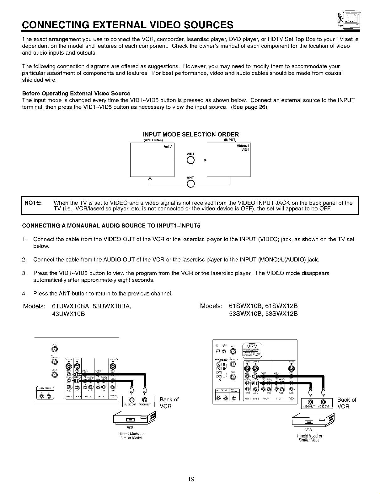
Before Operating External Video Source
The input mode is changed every time the VID1-VID5 button is pressed as shown below. Connect an external source to the INPUT
terminal, then press the VID1-VID5 button as necessary to view the input source. (See page 26)
INPUT MODE SELECTION ORDER
(ANTENNA)
AntA
A ANT
NOTE:
CONNECTING A MONAURAL AUDIO SOURCE TO INPUTI~INPUT5
1. Connect the cable from the VIDEO OUT of the VCR or the laserdisc player to the INPUT (VIDEO) jack, as shown on the TV set
below.
2. Connect the cable from the AUDIO OUT of the VCR or the laserdisc player to the INPUT (MONO)/L(AUDIO) jack.
3. Press the VID1-VID5 button to view the program from the VCR or the laserdisc player. The VIDEO mode disappears
automatically after approximately eight seconds.
4. Press the ANT button to return to the previous channel.
Models: 61UWX10BA, 53UWX10BA, Models: 61SWX10B, 61SWX12B
When the TV is set to VIDEO and a video signal is not received from the VIDEO INPUT JACK on the back panel of the I
TV (i.e., VCR/laserdisc player, etc. is net connected or the video device is OFF), the set will appear to be OFF.
43UWX10B 53SWX10B, 53SWX12B
0
(INPUT)
%;',
I
I
O
I o IBackef
A DI00T V9EO0UT VCR
VCR
HtachiModelor
Sim larMo6M
19
®oO
[ O O ] Back of
_u0_T _D_OO_TVCR
VCR
HitachiModelor
SimilarModel

f_
CONNECTING EXTERNAL VIDEO SOURCES
CONNECTING A STEREO SOURCE TO INPUTI~INPUT5
1. Connect the cable from the VIDEO OUT of the VCR or the laserdisc player to the INPUT (VIDEO) jack, as shown on the TV set
below.
2. Connect the cable from the AUDIO OUT R of the VCR or the laserdisc player to the INPUT (AUDIO/R) jack.
3. Connect the cable from the AUDIO OUT L of the VCR or the laserdisc player to the INPUT (AUDIO/L) jack.
4. Press the VID1-VID5 button to view the program from the VCR or laserdisc player. The VIDEO icon disappears automatically
after approximately eight seconds.
5. Press the ANT button to return to the previous channel.
Models: 61UWX10BA, 53UWX10BA,
43UWX10B
T_
cor_Em_
oo 9
_Back of
VCR
VCR
Mlachi Model or
SimilarModel
<ooi
Models: 61SWX10B, 61SWX12B
53SWX10B, 53SWX12B
6o0
Backof
VCR
Jr i
VCR
Hitac_i M0del or
SimilarModel
s_F_ __,iD_) s.l_ ¸
@8 @
I_,F_IT I _pU 4 IN#IJT 5 51_t _ R
NOTES: 1,
Completely insert the connection cord plugs when connecting to rear panel jacks. The picture and sound that is
played back will be abnormal if the connection is loose.
2.
A single VCR can be used for VCR #1 and VCR #2, but note that a VCR cannot record its own video or line
output. (INPUT: 1 in example on page 13 or 14) Refer to your VCR operating guide for more information on line
input-output connections.
20
f_
CONNECTING EXTERNAL VIDEO SOURCES
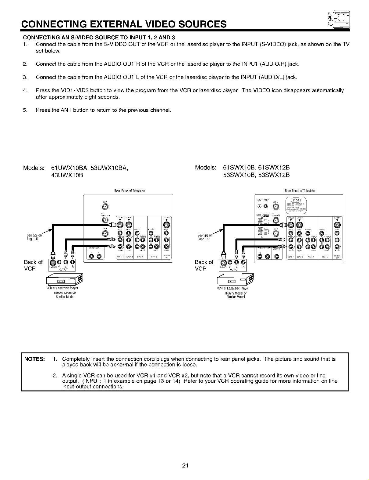
CONNECTING AN S-VIDEO SOURCE TO INPUT 1, 2 AND 3
1. Connect the cable from the S-VIDEO OUT of the VCR or the laserdisc player to the INPUT (S-VIDEO) jack, as shown on the TV
set below.
2. Connect the cable from the AUDIO OUT R of the VCR or the laserdisc player to the INPUT (AUDIO/R) jack.
3. Connect the cable from the AUDIO OUT L of the VCR or the laserdisc player to the INPUT (AUDIO/L) jack.
4. Press the VID1 -VID3 button to view the program from the VCR or laserdisc player. The VIDEO icon disappears automatically
after approximately eight seconds.
5. Press the ANT button to retum to the previous channel.
Models: 61UWX10BA, 53UWX10BA,
43UWX10B
RearPaneldrdevision
Page15 Page15
Back of _@, OO Back of @v@@L_1
VCR _' '0_> 'J VCR ["uE° 0 .....
VCRorLaserdiscPlayer VCRorLaserdiscPlayer
Hitachi M_el or HElachiModelor
Similar Model Similar M_el
Models: 61SWX10B, 61SWX12B
53SWX10B, 53SWX12B
Seetips on
RearPand of Idev s on
NOTES:
1. Completely insert the connection cord plugs when connecting to rear panel jacks. The picture and sound that is
played back will be abnormal if the connection is loose.
2. A single VCR can be used for VCR #1 and VCR #2, but note that a VCR cannot record its own video or line
output. (INPUT: 1 in example on page 13 or 14) Refer to your VCR operating guide for more information on line
input-output connections.
21
f_
CONNECTING EXTERNAL VIDEO SOURCES
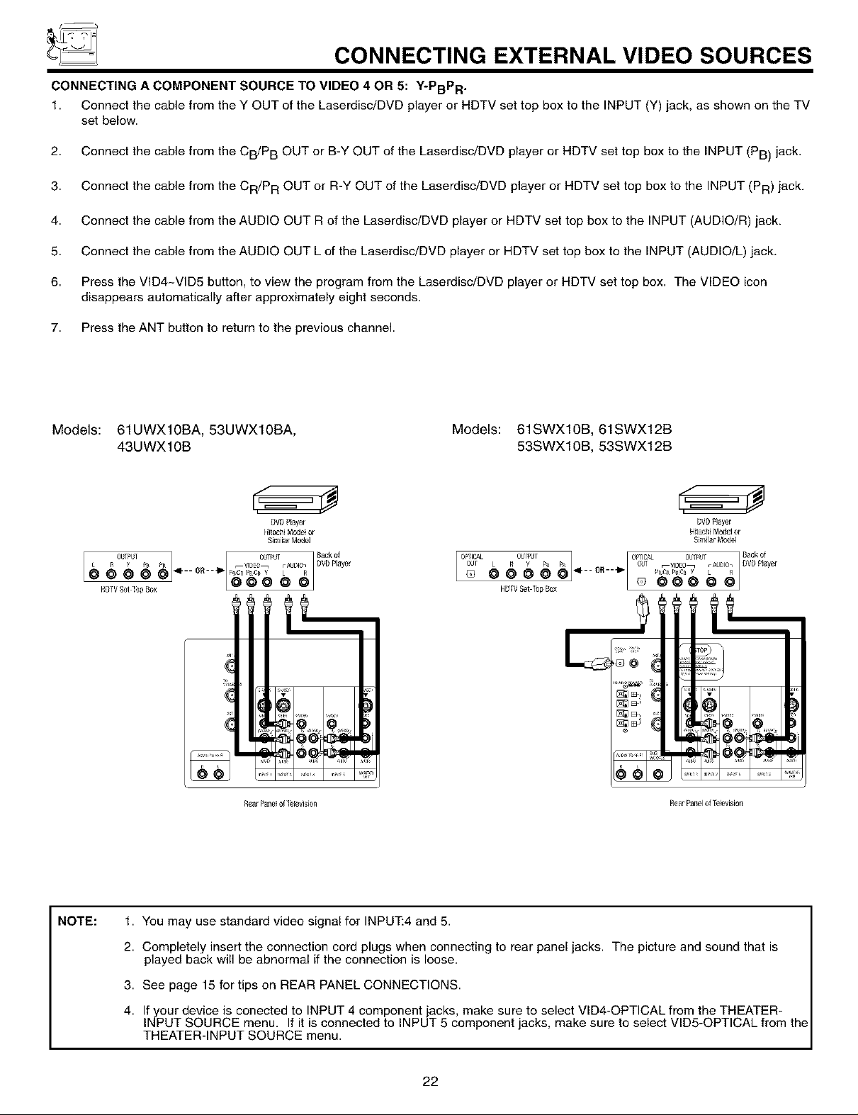
CONNECTING A COMPONENT SOURCE TO VIDEO 4 OR 5: Y-PBPR ,
1. Connect the cable from the Y OUT of the Laserdisc/DVD player or HDTV set top box to the INPUT (Y) jack, as shown on the TV
set below.
2. Connect the cable from the CB/P B OUT or B-Y OUT of the Laserdisc/DVD player or HDTV set top box to the INPUT (PB) jack.
3. Connect the cable from the CR/P R OUT or R-Y OUT of the Laserdisc/DVD player or HDTV set top box to the INPUT (PR) jack.
4. Connect the cable from the AUDIO OUT R of the Laserdisc/DVD player or HDTV set top box to the INPUT (AUDIO/R) jack.
5. Connect the cable from the AUDIO OUT L of the Laserdisc/DVD player or HDTV set top box to the INPUT (AUDIO/L) jack.
6. Press the VID4-VID5 button, to view the program from the Laserdisc/DVD player or HDTV set top box. The VIDEO icon
disappears automatically after approximately eight seconds.
7. Press the ANT button to return to the previous channel.
Models: 61UWX10BA, 53UWX10BA,
43UWX10B
DVDPlayer DVDPlayer
HitachiMode[ or HEtachiModelor
SimilarModel Simi]ar M_el
pR OR _" _D£{_ rAUDI07 DVD Player
a6oa, o.oeo
HD_VSet _bp _ox HDTVSetlbp Box
.... p_gR PBCB Y L R
RearPanelof ]%levision RearPaneloffeleuision
Models: 61SWX10B, 61SWX12B
53SWX10B, 53SWX12B
Backer
DVDPlayer
!
.... ....
NOTE:
1. You may use standard video signal for INPUT:4 and 5.
2. Completely insert the connection cord plugs when connecting to rear panel jacks. The picture and sound that is
played back will be abnormal if the connection is loose.
3. See page 15 for tips on REAR PANEL CONNECTIONS.
4. If your device is conected to INPUT 4 component jacks, make sure to select VID4-OPTICAL from the THEATER-
INPUT SOURCE menu. If it is connected to INPUT 5 component jacks, make sure to select VID5-OPTICAL from the
THEATER-INPUT SOURCE menu.
22
THE GENIUS REMOTE CONTROL
In addition to controlling all the functions on your HITACHI Projection TV, the new remote control is designed to operate different
types of VCRs, CATV (Cable TV) converters, set-top-box, satellite receiver, DVD players, and other audio/video equipment with
one touch. Basic operation keys are grouped together in one area.
To operate your TV, point the remote control at the remote sensor of the TV and press the TV button. The TV button will blink,
indicating that the remote will now control your television.
To operate your VCR, point the remote at the remote sensor of the VCR and press the VCR button. The VCR button will blink,
indicating that the remote will now control your VCR. (See page 30 for instructions on how to program the remote to control your
VCR.)
To operate your cable box, point the remote at the remote sensor of the cable box and press the CABLE (CBL) button. The CBL
button will blink, indicating that the remote will now control your cable box. (See page 31 for instructions on how to program the
remote to control your cable box.)
To operate your set-top-box or satellite receiver point the remote at the remote sensor of the set-top-box and press the SET-TOP-
BOX (STB) button. The STB button will blink, indicating that the remote will now control your set-top-box. If you have a satellite
receiver, use this button to prorame your satellite receiver. (See page 32 for instructions on how to program the remote to control
your set-top-box.)
To operate your DVD player, point the remote at the remote sensor of the DVD player and press the DVD button. The DVD button
will blink, indicating that the remote will now control your DVD player. (See page 33 for instruction on how to program the remote
to control your DVD player.)
To operate additional audio/video equipment, point the remote at the remote sensor of the component you wish to control and
press the AVl, AV2 or AV3 button. This button will blink, indicating that the remote will now control the desired component. (See
page 34 for instructions on how to program the remote to control additional AudioNideo equipment.)
-@
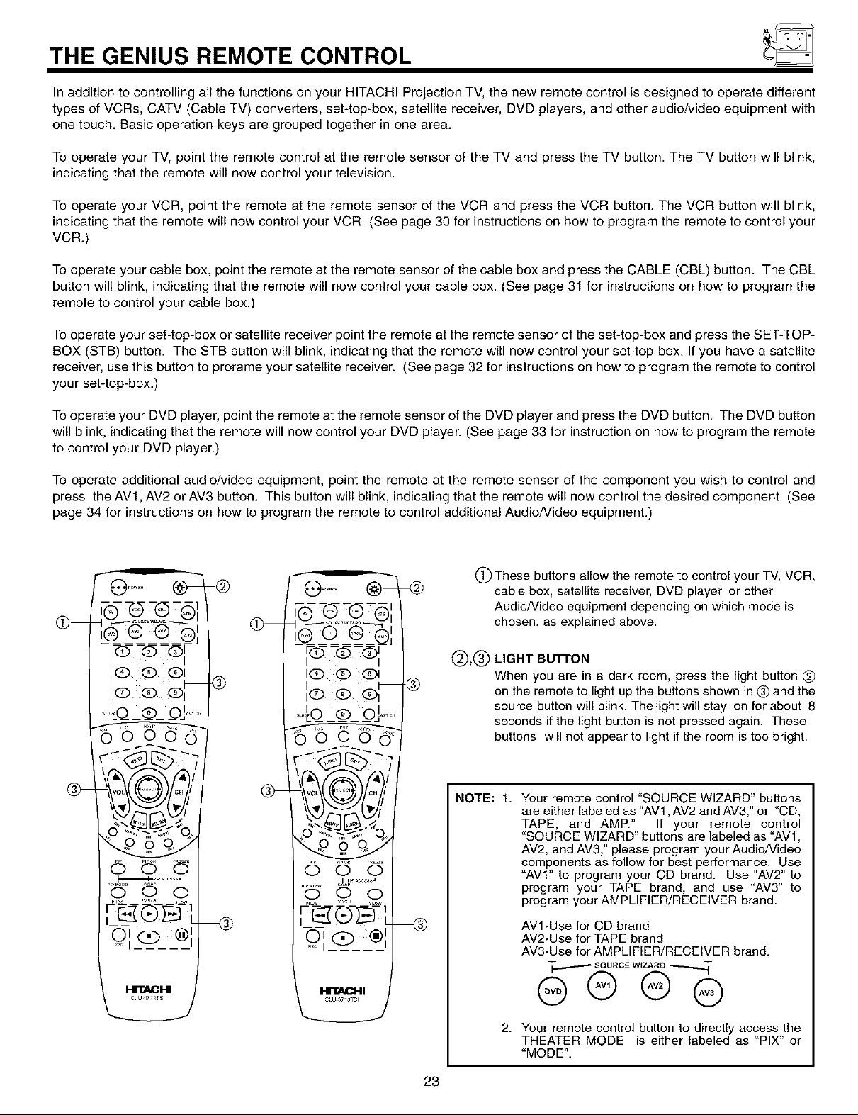
(_ These buttons allow the remote to control your TV, VCR,
cable box, satellite receiver, DVD player, or other
Audio/Video equipment depending on which mode is
chosen, as explained above.
le@ e @,
(_)_(_) LIGHT BUTTON
@-
I(E) qD qDI
I(z) C) C) II
I I
®
-@
When you are in a dark room, press the light button @)
on the remote to light up the buttons shown in (_ and the
source button will blink. Thelight will stay on for about 8
seconds if the light button is net pressed again. These
buttons will net appear to light if the room is too bright.
NOTE: 1. Your remote control "SOURCE WIZARD" buttons
are either labeled as "AV1, AV2 and AV3," or "CD,
TAPE, and AMP." If your remote control
"SOURCE WIZARD" buttons are labeled as "AVl,
AV2, and AV3," please program your Audio/Video
components as follow for best performance. Use
"AVl" to program your CD brand. Use "AV2" to
program your TAPE brand, and use "AV3" to
program your AMPLIFIER/RECEIVER brand.
AVl-Use for CD brand
AV2-Use for TAPE brand
AV3-Use for AMPLIFIER/RECEIVER brand.
I--ll"_O_H
c_u5711r_
23
2. Your remote control button to directly access the
THEATER MODE is either labeled as "PIX" or
"MODE".
 Loading...