

Hitachi 61SWX01W User Manual
PROJECTION COLOR TV
OPERATING GUIDE
_1__.,_1_
IMPORTANT SAFEGUARDS
FIRST TIME USE
THE GENIUS
REMOTE CONTROL
ULTRATEC BIT-MAP
ON-SCREEN DISPLAY
2-4
5-24
25-37
38-68
USEFUL INFORMATION INDEX 69-72
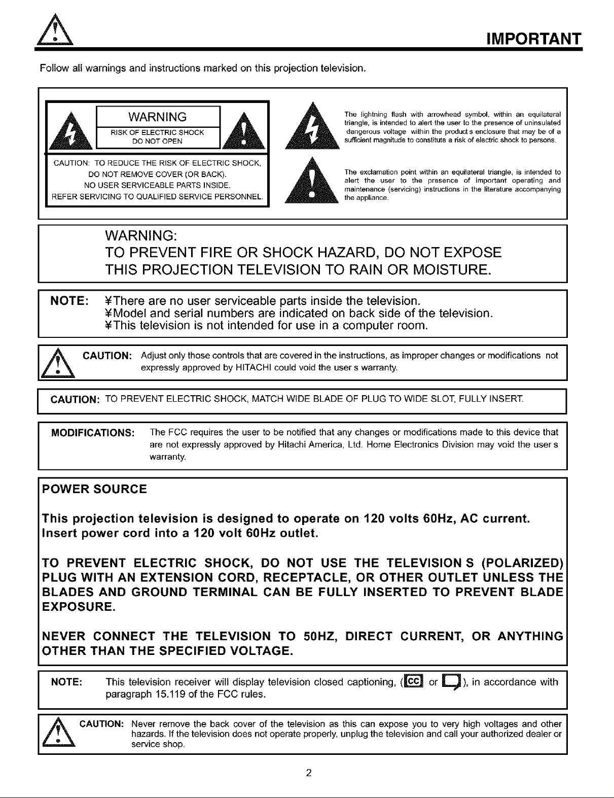
Follow all warnings and instructions marked on this projection television.
IMPORTANT
WARNING
RISK OF ELECTRIC SHOCK
DO NOT OPEN
CAUTION: TO REDUCE THE RISK OF ELECTRIC SHOCK,
DO NOT REMOVE COVER (OR BACK).
NO USER SERVICEABLE PARTS INSIDE.
REFER SERVICING TO QUALIFIED SERVICE PERSONNEL.
triangle, is intended to alert the user to the presence of uninsulatod
dangerous voltage within the products enclosure that may be of a
The lightning flash with arrowhead symbol, within an equilateral
sufficient magnitude to constitute a risk of electric shock to persons.
The exclamation point within an equilateraltriangle, is intended to
alert the user to the presence of impo_ant operating and
maintenance (servicing)instructions in the literature accompanying
the appliance.
WARNING:
TO PREVENT FIRE OR SHOCK HAZARD, DO NOT EXPOSE
THIS PROJECTION TELEVISION TO RAIN OR MOISTURE.
NOTE: ¥There are no user serviceable parts inside the television.
¥Model and serial numbers are indicated on back side of the television.
¥This television is not intended for use in a computer room.
CAUTION: Adjust only those controls that are covered in the instructions, as improper changes or modifications notexpressly approved by HITACHI could void the user s warranty.
CAUTION: TO PREVENT ELECTRIC SHOCK, MATCH WIDE BLADE OF PLUG TO WIDE SLOT, FULLY INSERT.
I
I
MODIFICATIONS: The FCC requires the user to be notified that any changes or modifications made to this device that
are not expressly approved by Hitachi America, Ltd. Home Electronics Division may void the user s
I
POWER SOURCE
This projection television is designed to operate on 120 volts 60Hz, AC current.
Insert power cord into a 120 volt 60Hz outlet.
TO PREVENT ELECTRIC SHOCK, DO NOT USE THE TELEVISION S (POLARIZED)
PLUG WITH AN EXTENSION CORD, RECEPTACLE, OR OTHER OUTLET UNLESS THE
BLADES AND GROUND TERMINAL CAN BE FULLY INSERTED TO PREVENT BLADE
EXPOSURE.
NEVER CONNECT THE TELEVISION TO 50HZ, DIRECT CURRENT, OR ANYTHIN(
OTHER THAN THE SPECIFIED VOLTAGE.
NOTE: This television receiver will display television closed captioning, (_C'_ or _U ), in accordance with
paragraph 15.119 of the FCC rules.
warranty.
I
_ CAUTION: Never remove the back cover of the television as this can expose you to very high voltages and other
hazards. If the television does not operate properly, unplug the television and call your authorized dealer or
service shop.
2
SAFETY TIPS
IMPORTANT SAFEGUARDS
CAUTION: ¥ Read all of these instructions. SAFETY POINTS YOU SHOULD KNOW ABOUT
¥ Save these instructions for later use. YOUR HITACHI PROJECTION TELEVISION
¥ Follow all warnings and instructions marked
on the television.
Our reputation has been built on the quality, performance, and ease of service of HITACHI televisions.
Safety is also foremost in our minds in the design of these units. To help you operate these products properly, this section illustrates safety tips which
will be of benefit to you. Please read it carefully and apply the knowledge you obtain from it to the proper operation of your HITACHI television.
Please fill out your warranty card and mail it to HITACHI. This will enable HITACHI to notify you promptly in the improbable event that a safety
problem should be discovered in your product model.
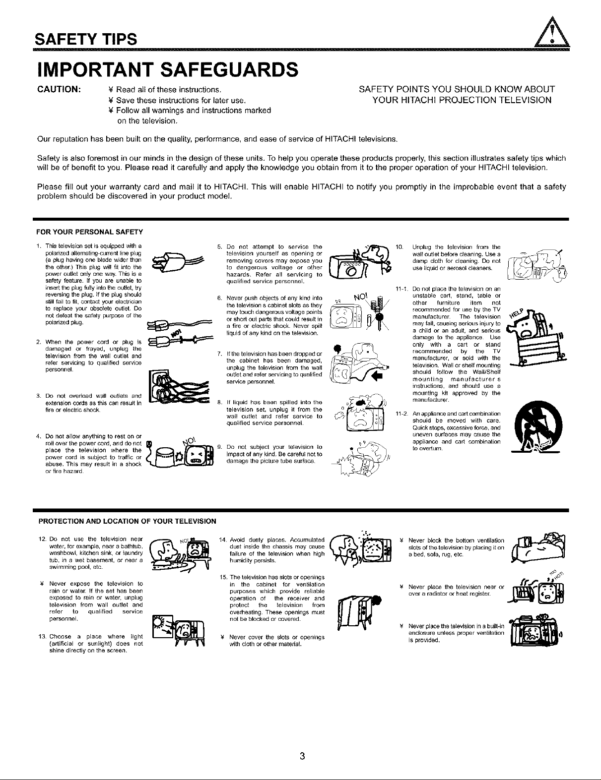
FORYOURPERSONALSAFETY
t This television set is equipped with a
polarized altemating-c=trrent line pl=_g
(a p_ug having one blade wider than
Re othen) This plug will _ into the
power cutlet only one way This is a
safety festure If you are unable to
insert the plug fully into the ou_Jst,ay
reversing the plug. If the plug should
still fail to fit, contact your electridan
to replace your obsolete outlet¸ Do
not defeat Re safety purpose of the
polarized plug¸
2 When the power cord or plug is
damaged or frayed, unplug the
television from the wall outlet and
refer servicing to qualified service
personnel¸
3 DO not overload wail ont_ets and
extens{on cords as this can result in
fire or electric shock¸
4 Do not allow anything to rest on or
roll over the power cord, and do not _ _P_L"_-_ 9.
place the television where the
power cord is suPject to traffic or
abuse_ This may result in a shock
or fire hazard_
5. Do not attempt to service the
television yourself as opening or
removing covers may expose you
to dangerous voltage or other
hazards¸ Refer all servicing to
qualified service personnel.
6.
Never p=tsh objects of any kind into
the television s cabinet slots as they
may touch dangerous voltage points
or short out pads that could result in
a fee or electric shock¸ Never spili
liquid of any kind on the television¸
7.
If the television has been dropped or
the cabinet has been damaged,
unplug the television from the walt
oubet and refer servicing to qualified
service personl3el
If liquid has been spilled into the
television set, unplug it from the
wall outlet and refer service to
qualified service personnel¸
Do not subject your television to
impact of any kind 8e careful not to
damage the picture tube sur fece
10. Unplug the television from the
wall outlel before cleaning. Use a
damp cloth for cleaning¸ DO not
use liquid or aero_ot cfeaners
11-t Do not ptace the television on an
unstabte cart, stand, table or
other furniture item not
recommended for use by the TV
manufacturer¸ The television
may fall causing serious injury to
a child or an adutt, and serious
damage to the appliance¸ Use
only with a cart or stand
recommended by the TV
manufacturer, or sold with the
television. Wall or shelf mounting
should follow the Wall/Shelf
mounting m_nufacturer s
thsfructJons, and shouid use a
mounting kit approved by the
manufecturer
11-2 An apsliance and cant combinatbn
should be moved with care
Quick stops, excessive force, and
uneven surfeoes may cause the
appliance and cart combination
to overturn¸
PROTECTION AND LOCATION OF YOUR TELEVISION
t2 Do not use the television near
water, for exampIe, near a bathtub,
washbowl, kitchen sink, or laundry
tub, in a wel basement, or near a
swimming pool, etc
¥ Never expose the television to
rain or water If the set has been
exposed to rain or water, unplug
television from wall outlet and
refer to qualified service
personnel¸
t3 Choose a place where light
(artificial or sunlight) does not
shine direc_y on the screen¸
dust inside the chassis may cause
failure of the television when high
humidity persists
15 The television has slots or openings
in the cabinet for ventilstion
purposes which provide reliable
operation of the receiver and
protect the television from
overheating¸ These openings must
not be blocked or covered¸
¥ Never cover the slots or openings
with cloth or other material.
3
¥ Never block the bottom ventilation FrlL_J_
sfets of the television by placing it on
a bed, sofa, rug, etc
¥ Never place the television near or I,_=_ ''
over a radiator or heat register
¥ Never place the television in a built-in '_
is provided
enclosure unless proper ventilation _1_
IfJ- Ii"_°_
PROTECTION AND LOCATION OF YOUR TELEVISION
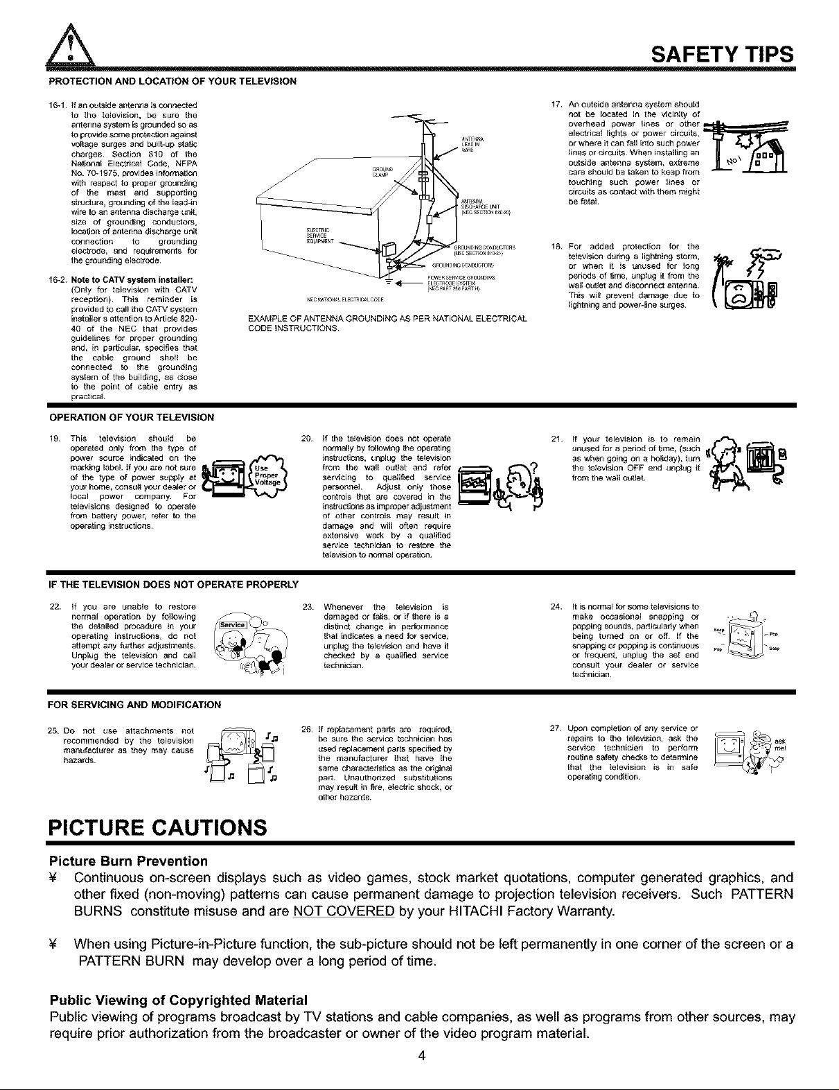
16-1. if an o=_tside antenna is connected
to the television, be s=_re the
antenna system is grounded so as
to provide some protection against
volfage surges and buithup static
charges¸ Section 810 of the
National Elecfacal Code, NFPA
No 70-1975, provides information
with respect to proper grounding
of the mast and supporting
structure, grounding of the tead-in
wire to an antenna discharge unit,
size of grounding conductors,
location of antenna discharge unit
connection to grounding
electrode, and requirements for
the grounding electrode
16-2. Note to CATV system installer:
(Only for television with CATV
reception)¸ This reminder is
provided to call the CATV system
installer s at fantion to Article 820-
40 of the NEC that provides
guidelines for proper grounding
and, in particular, specifies that
the cable ground shstl be
connected to the grounding
system of the building, 8s close
to the point of cable entry as
practical¸
OPERATION OF YOUR TELEVISION
19 This television should be
operated only from the type of
power source indicated on the
marking label. If you are not sure
of _he type of power suppEy at
your home_ consctl your dealer or
IocaE power oompany_ For
_elevisions designed to ogerate
from battery power, refer to the
operating instructions_
20 If the tstewsion does not operate
normally by following the operating
insttusttons, unplug the tetewsion
from the wall outlet and refar
servicing to qualified service
personnel¸ A_ust onty those
controls thst are covered in the
instructions as improper adjustment
of other controls may result in
damage and will often require
extensive work by a qualified
service fachnician to restore the
television to normal operation¸
_NTEN_
LE^DI_
SAFETY TIPS
17
An outside antenna system should
not be located in the vicinity of
overhead power lines or other_
electrical lights or power circuits,
or where it can fall into such power
tines or circuits¸ When installing an
outside antenna system, extreme
care should be taken to keep from
touching such power lines or
circuits as coofact with them might
be fatal.
18
For added protection for the
television dudng 8 lightning storm,
or when it is unused for long
periods of time, unplug it from the
wall oufiet and disconnect antenna¸
This wilt prevent damage due to
lightning and power-line surges¸
21 if yo=_r television is to remain
unused for 8 period of time, (such j
as whengoingonaholiday),t=_rn _ _11_
the television OFF and unplag it
from the wal, o.,t,et _1_
IF THE TELEVISION DOES NOT OPERATE PROPERLY
22. If yOU are unable to restore
normal operation by foltowing
the detailed procedure in your
operating instructions, do not
attempt any further adjustments
Unplug the television and call
your dealer or service technician¸
23 Whenever the television is
damaged or fails, or if there is a
distinct change in pe_farmance
that indicates a need for service,
unplug the television and have it
checked by a qualified service
technician¸
24. It iS normal for some televisions to
make occasional snapping or -_
being turned on or Off If the
0o00agsounds0ortc., ,tywhen
snapping or popping is cOngRUOUS
or frequent, unplug the set and
consult your dealer or service
technidan
FOR SERVICING AND MODIFICATION
27.
25 DO not use attachments not
recommended by the television
man_dacthret as they may cause
hazards
26 if replacement parts are required,
be s=_re the service technician has
used replacement parts specified by
the manufacturer that have the
same characfadstJcs as the odginal
part Unauthorized substitutions
may result in fire, elecfac shock, or
other hazards.
Upon complefion of any service or
repairs to the telewsion, ask the
service technician to perform
routine safety cheeks to determine
that the television is in safe
operating condition
PICTURE CAUTIONS
Picture Burn Prevention
¥ Continuous on-screen displays such as video games, stock market quotations, computer generated graphics, and
other fixed (non-moving) patterns can cause permanent damage to projection television receivers. Such PATTERN
BURNS constitute misuse and are NOT COVERED by your HITACHI Factory Warranty.
¥ When using Picture-in-Picture function, the sub-picture should not be left permanently in one corner of the screen or a
PATTERN BURN may develop over a long period of time.
Public Viewing of Copyrighted Material
Public viewing of programs broadcast by TV stations and cable companies, as well as programs from other sources, may
require prior authorization from the broadcaster or owner of the video program material.
4
ACCESSORIES
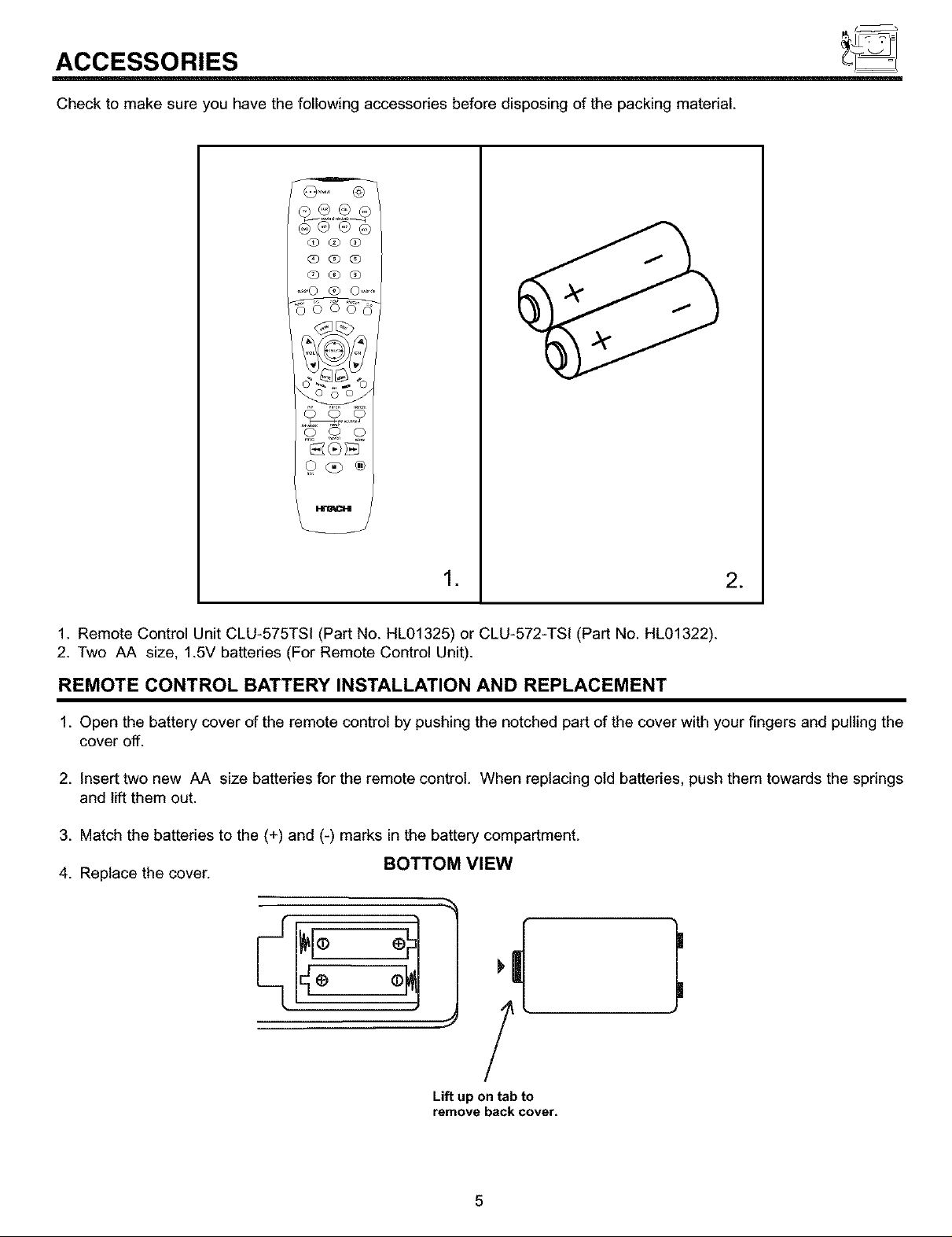
Check to make sure you have the following accessories before disposing of the packing material.
G G G
G Q Q
Q O G
.... 0 @ 0 ......
o o o
.
*
1. Remote Control Unit CLU-575TSI (Part No. HL01325) or CLU-572-TSI (Part No. HL01322).
2. Two AA size, 1.5V batteries (For Remote Control Unit).
REMOTE CONTROL BATTERY INSTALLATION AND REPLACEMENT
1. Open the battery cover of the remote control by pushing the notched part of the cover with your fingers and pulling the
cover off.
2. Insert two new AA size batteries for the remote control. When replacing old batteries, push them towards the springs
and lift them out.
3. Match the batteries to the (+) and (-) marks in the battery compartment.
4. Replace the cover.
BOTTOM VIEW
Lift up on tab to
remove back cover.
5
HOW TO SET UP YOUR NEW HITACHI PROJECTION TV
ANTENNA
Unless your TV is connected to a cable TV system or to a centralized antenna system, a good outdoor color TV antenna is
recommended for best performance. However, if you are located in an exceptionally good signal area that is free from interference and
multiple image ghosts, an indoor antenna may be sufficient.
LOCATION
Select an area where sunlight or bright indoor illumination will not fall directly on the picture screen. Also, be sure that the location
selected allows a free flow of air to and from the perforated back cover of the set.
To avoid cabinet warping, cabinet color changes, and increased chance of set failure, do not place the TV where temperatures can
become excessively hot, for example, in direct sunlight or near a heating appliance, etc.
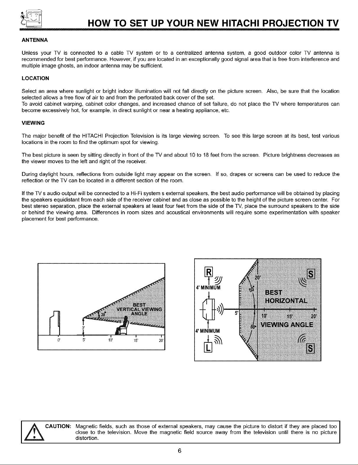
VIEWING
The major benefit of the HITACHI Projection Television is its large viewing screen. To see this large screen at its best, test various
locations in the room to find the optimum spot for viewing.
The best picture is seen by sitting directly in front of the TV and about 10 to 18 feet from the screen. Picture brightness decreases as
the viewer moves to the left and right of the receiver.
During daylight hours, reflections from outside light may appear on the screen. If so, drapes or screens can be used to reduce the
reflection or the TV can be located in a different section of the room.
If the TV s audio output will be connected to a Hi-Fi system s external speakers, the best audio performance will be obtained by placing
the speakers equidistant from each side of the receiver cabinet and as close as possible to the height of the picture screen center. For
best stereo separation, place the external speakers at least four feet from the side of the TV, place the surround speakers to the side
or behind the viewing area. Differences in room sizes and acoustical environments will require some experimentation with speaker
placement for best performance.
I
4' MINIMUM
3,
0'
5' I0' 15'
i
4'MINIMUM
CAUTION: Magnetic fields, such as those of external speakers, may cause the picture to distort if they are placed too
close to the television. Move the magnetic field source away from the television until there is no picture
distortion.
6
HOOK-UP CABLES AND CONNECTORS
Most video/audio connections between components can be made with shielded video and audio cables that have phono connectors.
For best performance, video cables should use 75-Ohm coaxial shielded wire. Cables can be purchased from most stores that sell
audio/video products. Below are illustrations and names of common connectors. Before purchasing any cables, be sure of the output
and input connector types required by the various components and the length of each cable.
-\
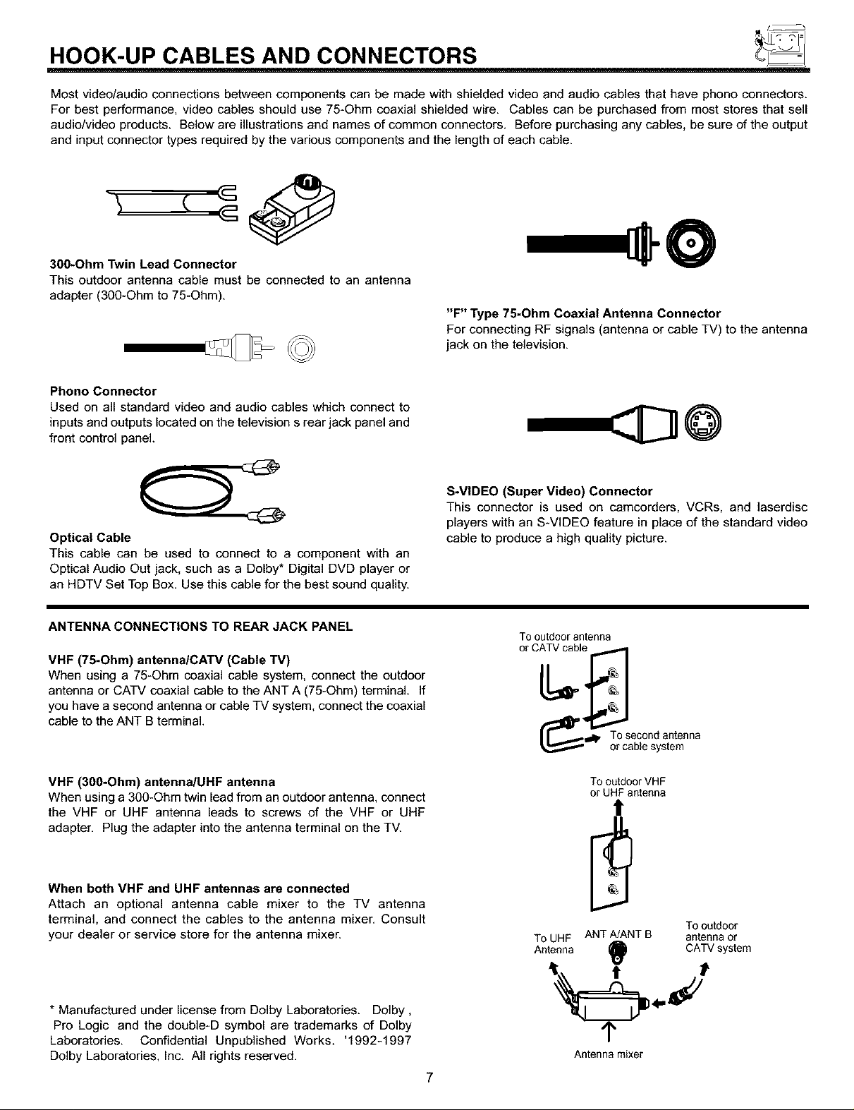
300-Ohm Twin Lead Connector
This outdoor antenna cable must be connected to an antenna
adapter (300-Ohm to 75-Ohm).
"F" Type 75-Ohm Coaxial Antenna Connector
For connecting RF signals (antenna or cable TV) to the antenna
jack on the television.
Phono Connector
Used on all standard video and audio cables which connect to
inputs and outputs located on the television s rear jack panel and
front control panel.
@
Optical Cable
This cable can be used to connect to a component with an
Optical Audio Out jack, such as a Dolby* Digital DVD player or
an HDTV Set Top Box. Use this cable for the best sound quality.
ANTENNA CONNECTIONS TO REAR JACK PANEL
VHF (75-Ohm) antennalCATV (Cable TV)
When using a 75-Ohm coaxial cable system, connect the outdoor
antenna or CATV coaxial cable to the ANT A (75-Ohm) terminal. If
you have a second antenna or cable TV system, connect the coaxial
cable to the ANT B terminal.
VHF (300-Ohm) antennalUHF antenna
When using a 300-Ohm twin lead from an outdoor antenna, connect
the VHF or UHF antenna leads to screws of the VHF or UHF
adapter. Plug the adapter into the antenna terminal on the TV.
When both VHF and UHF antennas are connected
Attach an optional antenna cable mixer to the TV antenna
terminal, and connect the cables to the antenna mixer. Consult
your dealer or service store for the antenna mixer.
S-VIDEO (Super Video) Connector
This connector is used on camcorders, VCRs, and laserdisc
players with an S-VIDEO feature in place of the standard video
cable to produce a high quality picture.
To outdoor antenna
or CATV cable
To second antenna
or cable system
To outdoor VHF
or UHF antenna
!
Tooutdoor
ToUHF ANTAJANTB antennaor
Antenna
_) C,_;Vsystem
* Manufactured under license from Dolby Laboratories. Dolby,
Pro Logic and the double-D symbol are trademarks of Dolby
Laboratories. Confidential Unpublished Works. '1992-1997
Dolby Laboratories, Inc. All rights reserved.
1"
Antenna mixer
7
POWER INPUT
FRONT PANEL CONTROLS
FRONT VIEW
HITACHI
®®® @ @
,_ Push open door and
CH+
POWER INPUT
© o o
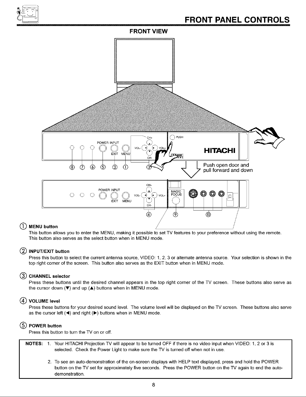
(_ MENU button
This button allows you to enter the MENU, making it possible to set TV features to your preference without using the remote.
This button also serves as the select button when in MENU mode.
(_ INPUT/EXIT button
Press this button to select the current antenna source, VIDEO: 1, 2.3 or alternate antenna source. Your selection is shown in the
top right corner of the screen. This button also serves as the EXIT button when in MENU mode.
(_) CHANNEL selector
Press these buttons until the desired channel appears in the top right corner of the TV screen. These buttons also serve as
the cursor down (T) and up (A) buttons when in MENU mode.
(_ VOLUME level
Press these buttons for your desired sound level. The volume level will be displayed on the TV screen. These buttons also serve
as the cursor left (,) and right (1_) buttons when in MENU mode.
©©©
EXIT MENU
pull forward and down
(_ POWER button
Press this button to turn the TV on or off.
NOTES: 1. Your HITACHI Projection TV will appear to be turned OFF if there is no video input when VIDEO: 1, 2 or 3 is
selected. Check the Power Light to make sure the TV is turned off when not in use.
2. To see an auto-demonstration of the on-screen displays with HELP text displayed, press and hold the POWER
button on the TV set for approximately five seconds. Press the POWER button on the TV again to end the auto-
demonstration.
8
FRONT PANEL CONTROLS
(_) POWER light
You will see a red light when the TV is turned on.
(_ AI (Artificial Intelligence) sensor
The Artificial Intelligence sensor will make automatic picture adjustments depending on the amount of light in the room to give the
best picture, (see page 60)
(_) REMOTE CONTROL sensor
Point your remote at this area when selecting channels, adjusting volume, etc.
(_ MAGIC FOCUS
Use this button to adjust your picture quality to optimum performance, (see page 47)
(_) FRONT INPUT JACKS (for VIDEO: 3)
Use these audio/video jacks for a quick hook*up from a camcorder or VCR to instanBy view your favorite show or new recording.
Press the INPUT button until VIDEO: 3 appears in the top right corner of the TV screen. If you have mono sound, insert the audio
cable into the left audio jack.
9
FRONT PANEL JACKS AND CONNECTIONS
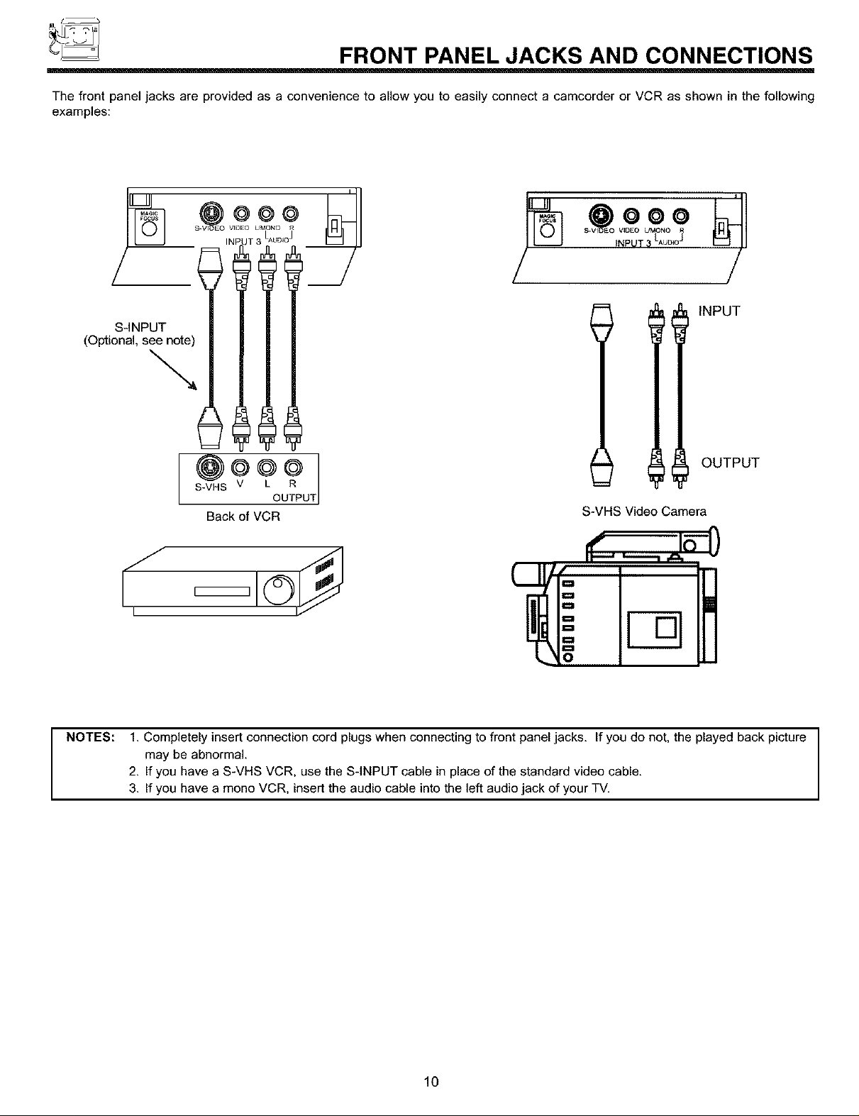
The front panel jacks are provided as a convenience to allow you to easily connect a camcorder or VCR as shown in the following
examples:
s- IDEO NPUT_AuDIo j
Qvo
(Optional, S__
. _UT 3 LAUD_°]
/
IllNPuT
OUTPUT
S-VHS V
Back of VCR
UT
S-VHS Video Camera
NOTES: 1. Completely insert connection cord plugs when connecting to front panel jacks. If you de not, the played back picture
may be abnormal.
2. If you have a S-VHS VCR, use the S-INPUT cable in place of the standard video cable.
3. If you have a mone VCR, insert the audio cable into the left audio jack of your TV.
10
REAR PANEL JACKS
(_ OPTICAL
iNPUT
@ ®®
ANTA
O COAXIALiNPUT
REAR SPI_KER
_O_LY
TO
CONVERTER
ANT B
VIDEO y
@O
S-ViDEO
V
V@EO Y
S-VIDE0•
Y
V@EO
@
MONO)/L
AUDIO
AUDIO iNPUT1 iNPUT2 MONITOR
TOHi-Fi OUT j
AUDIO
AUDIO
T T ' T
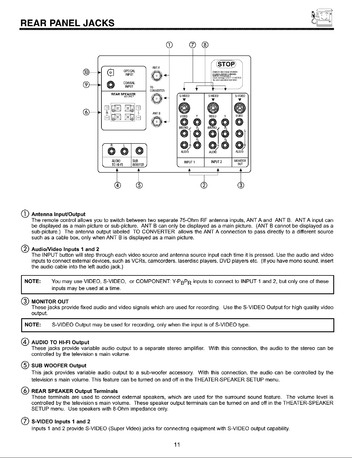
(_) Antenna Input/Output
The remote control allows you to switch between two separate 75-Ohm RF antenna inputs, ANT A and ANT B. ANT A input can
be displayed as a main picture or sub-picture. ANT B can only be displayed as a main picture. (ANT B cannot be displayed as a
sub-picture.) The antenna output labeled TO CONVERTER allows the ANT A connection to pass directly to a different source
such as a cable box, only when ANT B is displayed as a main picture.
(_) AudioNideo Inputs 1 and 2
The INPUT button will step through each video source and antenna source input each time it is pressed. Use the audio and video
inputs to connect external devices, such as VCRs, camcorders, laserdisc players, DVD players etc. (If you have mono sound, insert
the audio cable into the left audio jack.)
NOTE: You may use VIDEO, S-VIDEO, or COMPONENT: Y-PBPR inputs to connect to INPUT 1 and 2, but only one of these I
inputs may be used at a time.
I
I
MONITOR OUT
These jacks provide fixed audio and video signals which are used for recording. Use the S-VIDEO Output for high quality video
output.
NOTE: S-VIDEO Output may be used for recording, only when the input is of S-VIDEO type. I
(_) AUDIO TO HI-FI Output
These jacks provide variable audio output to a separate stereo amplifier. With this connection, the audio to the stereo can be
controlled by the television s main volume.
(_SUB WOOFER Output
This jack provides variable audio output to a sub-woofer accessory. With this connection, the audio can be controlled by the
television s main volume. This feature can be turned on and off in the THEATER-SPEAKER SETUP menu.
(_ REAR SPEAKER Output Terminals
These terminals are used to connect external speakers, which are used for the surround sound feature, The volume level is
controlled by the television s main volume. These speaker output terminals can be turned on and off in the THEATER-SPEAKER
SETUP menu. Use speakers with 8-Ohm impedance only.
(_) S-VIDEO Inputs 1 and 2
Inputs 1 and 2 provide S-VIDEO (Super Video) jacks for connecting equipment with S-VIDEO output capability.
11
I
REAR PANEL JACKS
Component: Y-PBPR Inputs
Inputs 1 and 2 provide Y-PBPR jacks for connecting equipment with this capability, such as a DVD player or Set Top Box.
NOTES:
(_ Coaxial Input
This jack provides high quality audio input from a Dolby Digital DVD player or HDTV Set Top Box. This input can be used for
VIDEO: 1 or VIDEO: 2 audio, as selected in the THEATER-INPUT SOURCE menu. (see page 67)
_ Optical Input
This jack provides high quality audio input from a Dolby Digital DVD player or HDTV Set Top Box. Use a digital optical cable to
connect your TV to a compatible device. This input can be used for VIDEO: 1 or VIDEO: 2 audio, as selected in the THEATER-
INPUT SOURCE menu. (see page 67)
1. DO NOT connect standard VIDEO or S-VIDEO to Input 1 or 2 when using Y-PBPR input.
2. When using the Y-PBP R input jacks, connect your components audio output to the TV s Input 1 or2 Left and Right Audio input jacks.
If your component has a Coaxial Out or Optical Out, use these connectors in place of the standard Audio L/R output jacks.
3. Your component outputs may be labeled Y, B-Y, and R-Y. In this case, connect the components B-Y output to the TV s PB input and
the components R-Y output to the TV a PR input.
4. Your component outputs may be labeled Y-CBC R. In this case, connect the component CB output to the TV s PB input and the
component CR output to the TV s PR input.
5. It may be necessary to adjust TINT to obtain optimum picture quality when using the Y-PBPR inputs. (See pages 59 and 60)
6. To ensure no copyright infringement, the MONITOR OUT output will be abnormal, when using the Y-PBPR jacks.
7. When using the Y-PBPR jacks, TV will automaticaUy change to SPLIT PIP mode. When you have Picture-in-Picture on and are
viewing a Y-PBPR input, only SPLIT mode is possible. (see page 29)
NOTE:
I
This TV s optical digital input jack fully complies with the international standard governing this type of jack (IEC958), and
is designed for connection to a Dolby Digital (AC-3 or PCM) DVD Player or Dolby Digital (AC-3 or PCM) HDTV Set Top
Box. Older equipment, some of which is not fully compliant with IEC958, may not be compatible with the Dolby Digital
bitstream. Such a connection using anything other than Dolby Digital AC-3 or PCM bitstream could create a high noise
level, causing damage to your speakers.
12
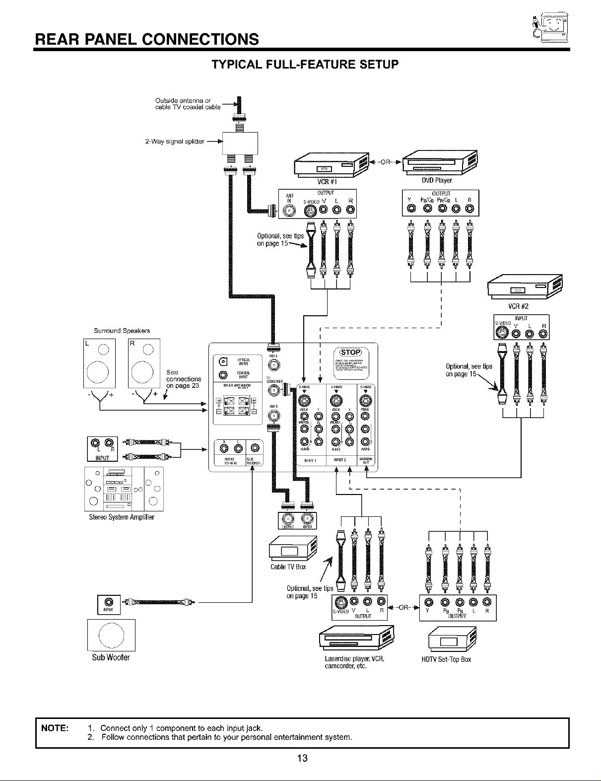
REAR PANEL CONNECTIONS
TYPICAL FULL-FEATURE SETUP
2-Waysignalsplitter
SurroundSpeakers
I
Illl
I
I
I
I
i
I
StereoSystemAmplifier
connections
]NFa_r
COAXI_IN_T
REaRS_EA_ER
Optional,seetips
onpage15
NOTE:
SubWoofer
1. Connect only 1 component to each input jack.
2, Follow connections that pertain to your personal entertainment system,
13
I
L
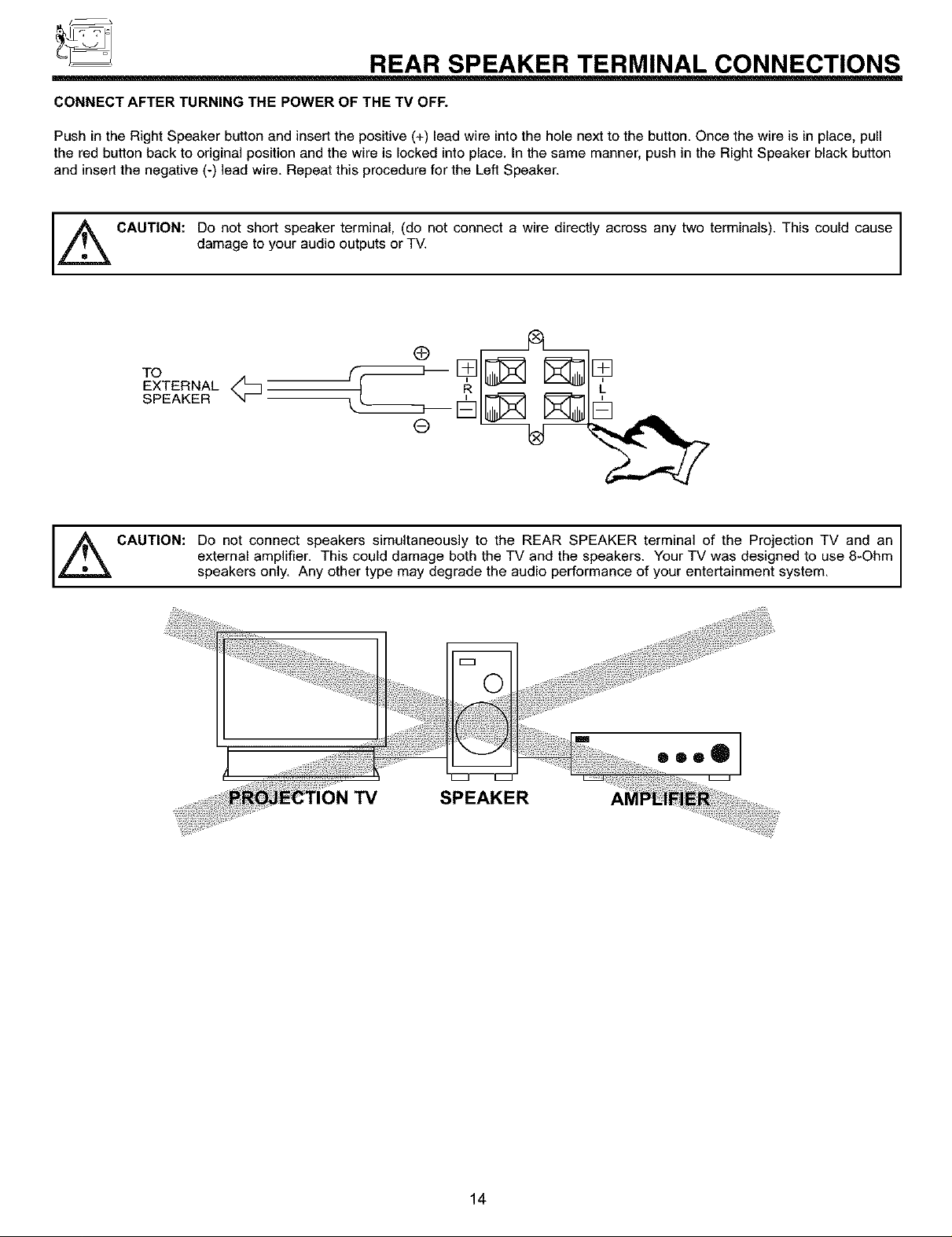
_ REAR SPEAKER TERMINAL CONNECTIONS
CONNECT AFTER TURNING THE POWER OF THE TV OFF.
Push in the Right Speaker button and insert the positive (+) lead wire into the hole next to the button. Once the wire is in place, pull
the red button back to original position and the wire is locked into place. In the same manner, push in the Right Speaker black button
and insert the negative (-) lead wire. Repeat this procedure for the Left Speaker.
IZ_. CAUTION: Do not short speaker terminal, (do not connect a wire directly across any two terminals). This could cause
damage to your audio outputs or TV.
To r
SPEAKER
®
_ CAUTION: Do not connect speakers simultaneously to the REAR SPEAKER terminal of the Projection TV and an
external amplifier. This could damage both the TV and the speakers. Your TV was designed to use 8-Ohm
speakers only. Any other type may degrade the audio performance of your entertainment system.
TV SPEAKER
14
TIPS ON REAR PANEL CONNECTIONS
TIPS ON REAR PANEL CONNECTIONS
S-VIDEO connections are provided for high performance laserdisc players, VCRs etc. that have this feature. Use these connections
in place of the standard video connection if your device has this feature.
If your device has only one audio output (mono sound), connect it to the left audio jack on the television.
Refer to the operating guide of your other electronic equipment for additional information on connecting your hook-up cables.
A single VCR can be used for VCR #1 and VCR #2, but note that a VCR cannot record its own video or line output (INPUT: 1 in the
example on page 13). Refer to your VCR operating guide for more information on line input-output connections.
You may use VIDEO, S-VIDEO, or COMPONENT: Y-PBPR inputs to connect to Input 1 or Input 2, but only one of these may be
used at a time.
Connect only 1 component (VCR, DVD player, camcorder, etc.) to each input jack.
COMPONENT: Y-PBPR connections are provided for high performance components, such as DVD players. Use these connections
in place of the standard video connection if your device has this feature.
When using the Y-PBPR input jacks, connect your components audio output to the TV s Input 1 or 2 Left and Right Audio input
jacks.
When using high performance equipment for VIDEO: 1 or VIDEO: 2 inputs, if it has an optical or coaxial output, you can use these
connections in place of the standard audio L/R connections.
Your component outputs may be labeled Y, B-Y, and R-Y. In this case, connect the components B-Y output to the TV s Pb input
and the components R-Y output to the TV s PR input.
Your component outputs may be labeled Y-CBC R, In this case, connect the components C B output to the TV s PB input and the
components CR output to the TV s PR input.
It may be necessary to adjust TINT to obtain optimum picture quality when using the Y-PBPR inputs. (See pages 59 and 60)
To ensure no copyright infringement, the MONITOR OUT output will be abnormal, when using the Y-PBPR jacks.
15
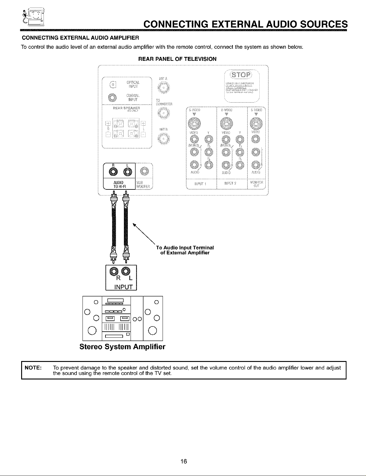
_ CONNECTING EXTERNAL AUDIO SOURCES
CONNECTING EXTERNAL AUDIO AMPLIFIER
TOcontrol the audio level of an external audio amplifier with the remote control, connect the system as shown below.
REAR PANEL OF TELEVISION
_0
RI£/',R t_t: EA_ El
N
R L
@@
AUDIO
TO HI-FI
To Audio Input Terminal
of External Amplifier
INPUT
0 _ 0
v A v A
v F_I F_- O0 v
0 iiiiiiiiiiii0
Stereo System Amplifier
NOTE: To prevent damage to the speaker and distorted sound, set the volume control of the audio amplifier lower and adjust
the sound using the remote control of the TV set.
16
CONNECTING EXTERNAL VIDEO SOURCES
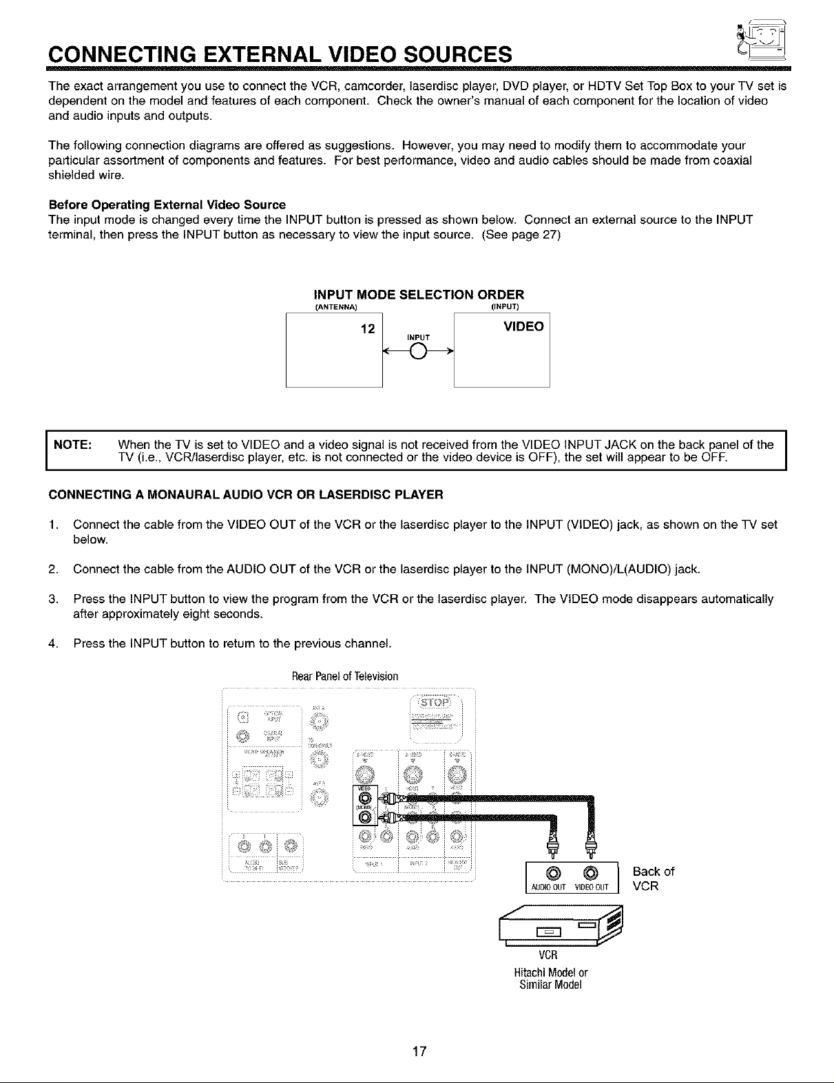
The exact arrangement you use to connect the VCR, camcorder, laserdisc player, DVD player, or HDTV Set Top Box to your TV set is
dependent on the model and features of each component. Check the owner's manual of each component for the location of video
and audio inputs and outputs.
The following connection diagrams are offered as suggestions. However, you may need to modify them to accommodate your
particular assortment of components and features. For best performance video and audio cables should be made from coaxial
shielded wire.
Before Operating External Video Source
The input mode is changed every time the INPUT button is pressed as shown below. Connect an external source to the INPUT
terminal, then press the INPUT button as necessary to view the input source. (See page 27)
INPUT MODE SELECTION ORDER
(ANTENNA) (INPUT)
12 VIDEO
INPUT
NOTE:
CONNECTING A MONAURAL AUDIO VCR OR LASERDISC PLAYER
1. Connect the cable from the VIDEO OUT of the VCR or the laserdisc player to the INPUT (VIDEO) jack, as shown on the TV set
below.
2. Connect the cable from the AUDIO OUT of the VCR or the laserdisc player to the INPUT (MONO)/L(AUDIO) jack.
3. Press the INPUT button to view the program from the VCR or the laserdisc player. The VIDEO mode disappears automatically
after approximately eight seconds.
4. Press the INPUT button to return to the previous channel.
When the TV is set to VIDEO and a video signal is not received from the VIDEO INPUT JACK on the back panel of the I
TV (i.e., VCR/laserdisc player, etc. is not connected or the video device is OFF), the set will appear to be OFF.
RearPanelof Television
_?_ %1_¸¸
4;'
<,<
i _•_..... _!_ i_'_ ii
I
I
17
i ii
AUDI VIDEOOUT
VCR
HitachiModelor
SimilarModel
l
Back of
VCR
CONNECTING EXTERNAL VIDEO SOURCES
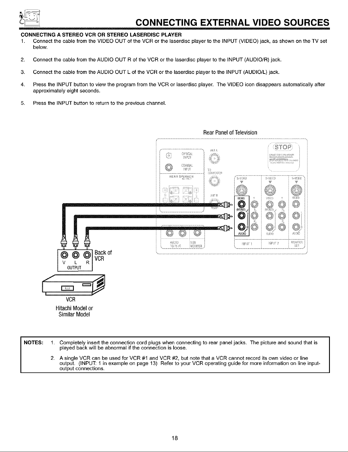
CONNECTING A STEREO VCR OR STEREO LASERDISC PLAYER
1. Connect the cable from the VIDEO OUT of the VCR or the laserdisc player to the INPUT (VIDEO) jack, as shown on the TV set
below.
2. Connect the cable from the AUDIO OUT R of the VCR or the laserdisc player to the INPUT (AUDIO/R) jack.
3. Connect the cable from the AUDIO OUT L of the VCR or the laserdisc player to the INPUT (AUDIO/L) jack.
4. Press the INPUT button to view the program from the VCR or laserdisc player. The VIDEO icon disappears automatically after
approximately eight seconds.
5. Press the INPUT button to return to the previous channel.
RearPanelof Television
I]'01;_,
i i w>,i,_i
I _.......................................................................CO?iiiilyii
i i I
i !i _ i i
=1111!iYIIK!!i=ii!1111;ii i
i I
NOTES: 1.
VCR
Hitachi Modelor
Similar Model
Completely insert the connection cord plugs when connecting to rear panel jacks. The picture and sound that is
played back will be abnormal if the connection is loose.
2.
A single VCR can be used for VCR #1 and VCR #2, but note that a VCR cannot record its own video or line
output. (INPUT: 1 in example on page 13) Refer to your VCR operating guide for more information on line input-
output connections.
18
CONNECTING EXTERNAL VIDEO SOURCES
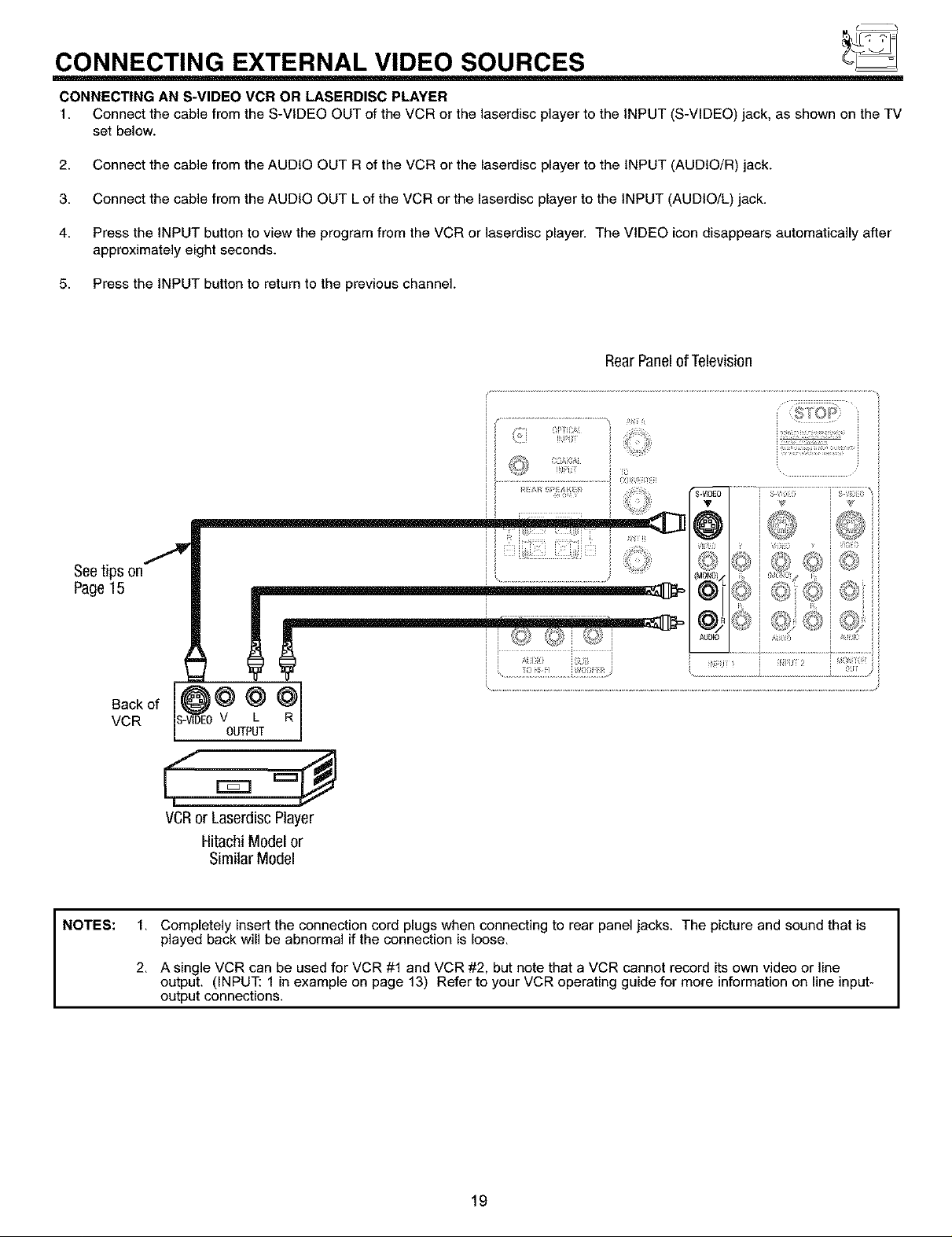
CONNECTING AN S-VIDEO VCR OR LASERDISC PLAYER
1. Connect the cable from the S-VIDEO OUT of the VCR or the laserdisc player to the INPUT (S-VIDEO) jack, as shown on the TV
set below.
2. Connect the cable from the AUDIO OUT R of the VCR or the laserdisc player to the INPUT (AUDIO/R) jack.
3. Connect the cable from the AUDIO OUT L of the VCR or the laserdisc player to the INPUT (AUDIO/L) jack.
4. Press the INPUT button to view the program from the VCR or laserdisc player. The VIDEO icon disappears automatically after
approximately eight seconds.
5. Press the INPUT button to return to the previous channel.
RearPanelof Television
Seetips on
Page15
NOTES:
7
Back of
VCR
VCRor LasercliscPlayer
1. Completely insert the connection cord plugs when connecting to rear panel jacks. The picture and sound that is
played back will be abnormal if the connection is loose.
2. A single VCR can be used for VCR #1 and VCR #2, but note that a VCR cannot record its own video or line
output. (INPUT: 1 in example on page 13) Refer to your VCR operating guide for more information on line input-
output connections.
V L R
OUTPUT
Hitachi Modelor
Similar Model
19
CONNECTING EXTERNAL VIDEO SOURCES
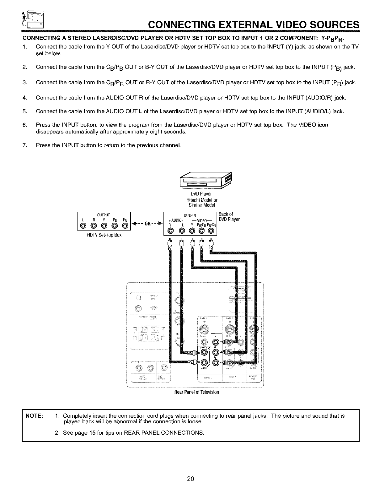
CONNECTING A STEREO LASERDISC/DVD PLAYER OR HDTV SET TOP BOX TO INPUT 1 OR 2 COMPONENT: Y-PBPR .
1. Connect the cable from the Y OUT of the Laserdisc/DVD player or HDTV set top box to the INPUT (Y) jack, as shown on the TV
set below.
2. Connect the cable from the CB/P B OUT or B-Y OUT of the Laserdisc/DVD player or HDTV set top box to the INPUT (PB) jack.
3. Connect the cable from the CR/P R OUT or R-Y OUT of the Laserdisc/DVD player or HDTV set top box to the INPUT (PR) jack.
4. Connect the cable from the AUDIO OUT R of the Laserdisc/DVD player or HDTV set top box to the INPUT (AUDIO/R) jack.
5. Connect the cable from the AUDIO OUT L of the Laserdisc/DVD player or HDTV set top box to the INPUT (AUDIO/L) jack.
6. Press the INPUT button, to view the program from the Laserdisc/DVD player or HDTV set top box. The VIDEO icon
disappears automatically after approximately eight seconds.
7. Press the INPUT button to return to the previous channel.
,#
DVDPlayer
HitachiModelor
SimilarModel
OUTPUT
L a Y PB PB
@@@@@
HDTVSet-TopBox
4 -- O_UT Back of
OR---ll_- _} __P_BP_I_rAUOIOnr--VIDEO_ DVDPIayeF
i/ .......................................................
<iii _i_iil_
_ _:{_i?¸¸
RearPanelofTelevision
NOTE: 1. Completely insert the connection cord plugs when connecting to rear panel jacks. The picture and sound that is
played back will be abnormal if the connection is loose.
2. See page 15 for tips on REAR PANEL CONNECTIONS.
2O
CONNECTING EXTERNAL VIDEO SOURCES
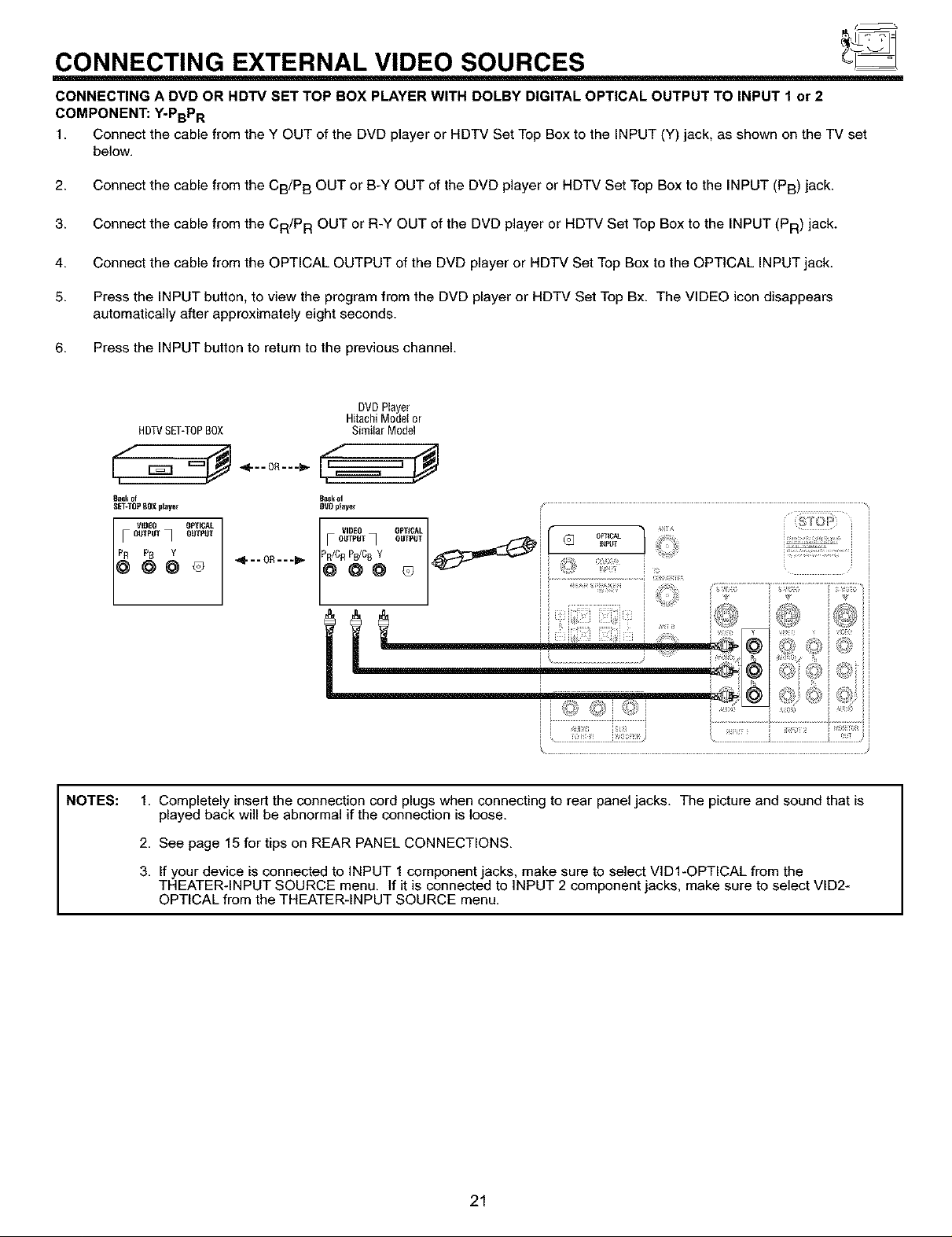
CONNECTING A DVD OR HDTV SET TOP BOX PLAYER WITH DOLBY DIGITAL OPTICAL OUTPUT TO INPUT 1 or 2
COMPONENT: Y-PBPR
1. Connect the cable from the Y OUT of the DVD player or HDTV Set Top Box to the INPUT (Y) jack, as shown on the TV set
below.
2. Connect the cable from the CB/P B OUT or B-Y OUT of the DVD player or HDTV Set Top Box to the INPUT (PB) jack.
3. Connect the cable from the CR/P R OUT or R-Y OUT of the DVD player or HDTV Set Top Box to the INPUT (PR) jack.
4. Connect the cable from the OPTICAL OUTPUT of the DVD player or HDTV Set Top Box to the OPTICAL INPUT jack.
5. Press the INPUT button, to view the program from the DVD player or HDTV Set Top Bx. The VIDEO icon disappears
automatically after approximately eight seconds.
6. Press the INPUT button to return to the previous channel.
DVDPlayer
HDTVSET-TOPBOX SimilarModel
8_lck of _ck OI
SET-TOP80X playe_ DVOplayer
HitachiModelor
NOTES:
F
1. Completely insert the connection cord plugs when connecting to rear panel jacks. The picture and sound that is
played back will be abnormal if the connection is loose.
2. See page 15 for tips on REAR PANEL CONNECTIONS.
3. If your device is connected to INPUT 1 component jacks, make sure to select VID1-OPTICAL from the
THEATER-INPUT SOURCE menu. If it is connected to INPUT 2 component jacks, make sure to select VID2-
OPTICAL from the THEATER-INPUT SOURCE menu.
J
21
CONNECTING EXTERNAL VIDEO SOURCES
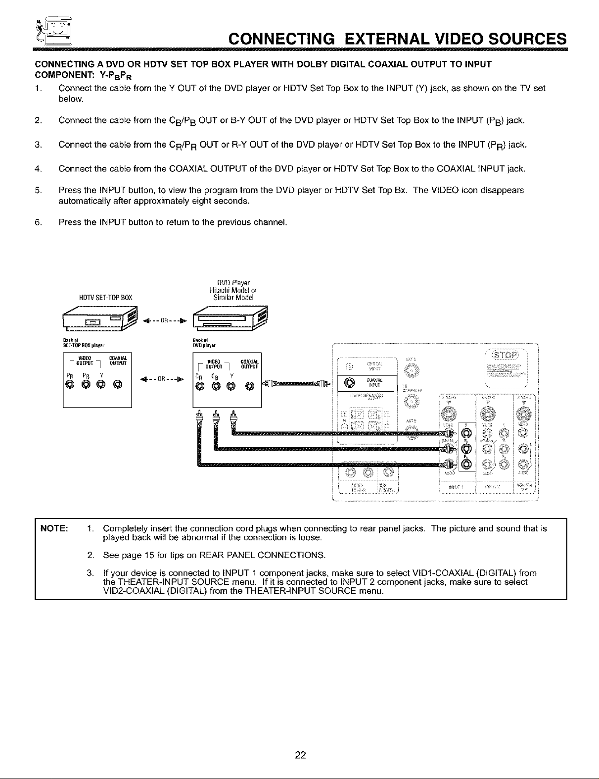
CONNECTING A DVD OR HDTV SET TOP BOX PLAYER WITH DOLBY DIGITAL COAXIAL OUTPUT TO INPUT
COMPONENT: Y-PBPR
1. Connect the cable from the Y OUT of the DVD player or HDTV Set Top Box to the INPUT (Y) jack, as shown on the TV set
below.
2. Connect the cable from the CB/P B OUT or B-Y OUT of the DVD player or HDTV Set Top Box to the INPUT (PB) jack.
3. Connect the cable from the CR/P R OUT or R-Y OUT of the DVD player or HDTV Set Top Box to the INPUT (PR) jack.
4. Connect the cable from the COAXIAL OUTPUT of the DVD player or HDTV Set Top Box to the COAXIAL INPUT jack.
5. Press the INPUT button, to view the program from the DVD player or HDTV Set Top Bx. The VIDEO icon disappears
automatically after approximately eight seconds.
6. Press the INPUT button to return to the previous channel.
DVDPlayer
HOWSET-TOPBOX SimiIarModel
HitachiModelor
Bad(ot lack ot
SET-TOp BOX player DVD player
VIDEO COP,XIAL
F OUTPUT_ OUTPUT
NOTE: 1.
Completely insert the connection cord plugs when connecting to rear panel jacks. The picture and sound that is
played back will be abnormal if the connection is loose.
2.
See page 15 for tips on REAR PANEL CONNECTIONS.
3.
If your device is connected to INPUT 1 component jacks, make sure to select VID1-COAXIAL (DIGITAL) from
the THEATER-INPUT SOURCE menu. If it is connected to INPUT 2 component jacks, make sure to select
VID2-COAXIAL (DIGITAL) from the THEATER-INPUT SOURCE menu.
L ' '
22
f_
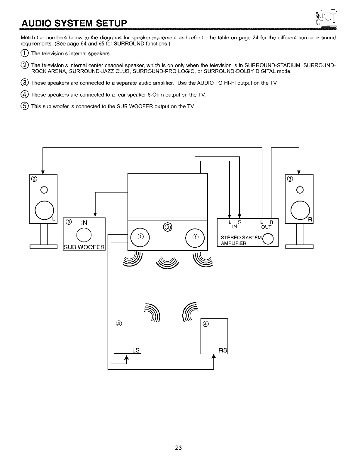
AUDIO SYSTEM SETUP
Match the numbers below to the diagrams for speaker placement and refer to the table on page 24 for the different surround sound
requirements. (See page 64 and 65 for SURROUND functions.)
(_The television s internal speakers.
The television s internal center channel speaker, which is on only when the television is in SURROUND-STADIUM, SURROUND-
ROCK ARENA, SURROUND-JAZZ CLUB, SURROUND-PRO LOGIC, or SURROUND-DOLBY DIGITAL mode.
(_) These speakers are connected to a separate audio amplifier. Use the AUDIO TO HI-FI output on the TV.
(_ These speakers are connected to a rear speaker 8-Ohm output on the TV.
(_) This sub woofer is connected to the SUB WOOFER output on the TV.
&
®
O
©
UB WOOFER
© ©
%
®
y 'V
OUT
STEREO SYSTEM ("'_
LINR L R
AMPLIFIER _-J
®
O
LS
23
 Loading...