

Page 1

LCD REAR PROJECTION
TELEVISION
Operating Guide for
50VG825, 55VG825, 60VG825
IMPORTANT SAFETY INSTRUCTIONS....................................................................................... 2-3
FIRST TIME USE ....................................................................................................................... 4-20
THE REMOTE CONTROL........................................................................................................ 21-38
ON-SCREEN DISPLAY............................................................................................................ 39-88
LAMP REPLACEMENT .............................................................................................................88-91
USEFUL INFORMATION.......................................................................................................... 92-97
LICENSE AGREEMENT..................................................................................................................98
APPENDIXES ..........................................................................................................................99-100
INDEX ...........................................................................................................................................101
As an Energy Star®Partner,
Hitachi, Ltd. has determined
that this product meets the
Energy Star®guidelines for
energy efficiency.
Page 2
2
SAFETY POINTS YOU SHOULD KNOW ABOUT
YOUR HITACHI LCD REAR PROJECTION
TELEVISION
Our reputation has been built on the quality,
performance, and ease of service of HITACHI
televisions.
Safety is also foremost in our minds in the design of
these units. To help you operate these products
properly, this section illustrates safety tips which will be
of benefit to you. Please read it carefully and apply the
knowledge you obtain from it to the proper operation of
your HITACHI television.
Please fill out your warranty card and mail it to
HITACHI. This will enable HITACHI to notify you
promptly in the improbable event that a safety problem
should be discovered in your product model.
Follow all warnings and instructions marked on
this television.
The lightning flash with arrowhead symbol,
within an equilateral triangle, is intended to
alert the user to the presence of
uninsulated “dangerous voltage” within the
product’s enclosure that may be of a sufficient
magnitude to constitute a risk of electric shock to a
person.
The exclamation point within an equilateral
triangle, is intended to alert the user to the
presence of important operating and
maintenance (servicing) instructions in the
literature accompanying the appliance.
READ BEFORE OPERATING EQUIPMENT
Follow all warnings and instructions marked on this
television.
1. Read these instructions.
2. Keep these instructions.
3. Heed all warnings.
4. Follow all instructions.
5. Do not use this apparatus near water.
6. Clean only with a dry cloth.
7. Do not block any ventilation openings. Install in
accordance with the manufacturer’s instructions.
8. Do not install near any heat sources such as
radiators, heat registers, stoves, or other apparatus
(including amplifiers) that produce heat.
9. Do not defeat the safety purpose of the polarized or
grounding-type plug. A polarized plug has two
blades with one wider than the other. A grounding
type plug has two blades and a third grounding
prong. The wide blade or the third prong are
provided for your safety. If the provided plug does
not fit into your outlet, consult an electrician for
replacement of the obsolete outlet.
10. Protect the power cord from being walked on or
pinched particularly at plugs, convenience
receptacles, and the point where they exit from the
apparatus.
11. Only use the attachments/accessories specified by
the manufacturer.
12. Use only with the cart, stand, tripod,
bracket, or table specified by the
manufacturer, or sold with the
apparatus. When a cart is used, use
caution when moving the cart/apparatus
combination to avoid injury from tip-over.
13. Unplug this apparatus during lightning storms or
when unused for long periods of time.
14. Refer all servicing to qualified service personnel.
Servicing is required when the apparatus has been
damaged in any way, such as power-supply cord or
plug is damaged, liquid has been spilled or objects
have fallen into apparatus, the apparatus has been
exposed to rain or moisture, does not operate
normally, or has been dropped.
15. Televisions are designed to comply with the
recommended safety standards for tilt and stability.
Do not apply excessive pulling force to the front, or
top, of the cabinet which could cause the product
to overturn resulting in product damage and/or
personal injury.
16. Follow instructions for wall, shelf or ceiling
mounting as recommended by the manufacturer.
17. An outdoor antenna should not be located in the
vicinity of overhead power lines or other electrical
circuits.
18. If an outside antenna is connected to the receiver
be sure the antenna system is grounded so as to
provide some protection against voltage surges and
built up static charges. Section 810 of the National
Electric Code, ANSI/NFPA No. 70-1984, provides
information with respect to proper grounding for the
mast and supporting structure, grounding of the
lead-in wire to an antenna discharge unit, size of
grounding connectors, location of antennadischarge unit, connection to grounding electrodes
and requirements for the grounding electrode.
Note to the CATV system installer: This reminder is
provided to call the CATV system installer’s attention to
Article 820-44 of the NEC that provides guidelines for
proper grounding and, in particular, specifies that the
cable ground shall be connected to the grounding
system of the building, as close to the point of cable
entry as practical.
Important Safety Instructions
CAUTION: TO REDUCE THE RISK OF ELECTRIC SHOCK,
DO NOT REMOVE COVER (OR BACK).
NO USER SERVICEABLE PARTS INSIDE.
REFER SERVICING TO QUALIFIED SERVICE PERSONNEL.
CAUTION
RISK OF ELECTRIC SHOCK
DO NOT OPEN
Page 3
Power source
This television is designed to operate on 120 volts
60 Hz, AC current. Insert the power cord into a 120 volt
60 Hz outlet.
To prevent electric shock, do not use the television’s
(polarized) plug with an extension cord, receptacle, or
other outlet unless the blades and ground terminal can
be fully inserted to prevent blade exposure.
Never connect the television to 50 Hz, direct current, or
anything other than the specified voltage.
Caution
Never remove the back cover of the
television as this can expose you to very
high voltages and other hazards. If the
television does not operate properly,
unplug the television and call your authorized dealer or
service center.
Caution
Adjust only those controls that are covered in the
instructions, as improper changes or modifications not
expressly approved by HITACHI could void the user’s
warranty.
Warning
• To reduce the risk of fire or electric shock, do not
expose this apparatus to rain or moisture.
• The television should not be exposed to dripping or
splashing and objects filled with liquids, such as
vases, should not be placed on the television.
Warning
• Do not place any objects on the top of the television
which may fall or cause a child to climb to retrieve
the objects.
Modifications
The FCC requires the user to be notified that any
changes or modifications made to this device that are
not expressly approved by Hitachi America, Ltd. Home
Electronics Division may void the user’s authority to
operate the equipment.
Note
This television receiver will display television closed
captioning, ( or ), in accordance with paragraph
15.119 and 15.122 of the FCC rules.
Public viewing of copyrighted material
Public viewing of programs broadcast by TV stations
and cable companies, as well as programs from other
sources, may require prior authorization from the
broadcaster or owner of the video program material.
This product incorporates copyright protection
technology that is protected by U.S. patents and other
intellectual property rights. Use of this copyright
protection technology must be authorized by
Macrovision Corporation, and is intended for home and
other limited consumer uses only unless otherwise
authorized by Macrovision. Reverse engineering or
disassembly is prohibited.
Note
This digital television is capable of receiving analog
basic, digital basic and digital premium cable television
programming by direct connection to a cable system
providing such programming. A CableCARD provided
by your cable operator is required to view encrypted
digital programming. Certain advanced and interactive
digital cable services such as video-on-demand, a cable
operator’s enhanced program guide and data-enhanced
television services may require the use of a set-top box.
For more information call your local cable company.
Note
• There are no user serviceable parts inside the
television.
• Model and serial numbers are indicated on back side
of the television.
Lead Notice
This product contains lead and a lamp that contains
mercury. Dispose of this product and its lamp in
accordance with applicable environmental laws. For
lamp recycling and disposal information, go to
www.lamprecycle.org. For product recycling and
disposal information contact your local government
agency or www.eRecycle.org (in California), the
Electronic Industries Alliance at www.eiae.org (in the
US) or the Electronic Product Stewardship Canada at
www.epsc.ca (in Canada).
FOR MORE INFORMATION, CALL 1-800-HITACHI.
3
Important Safety Instructions
Page 4
4
Accessories
First time use
Check to make sure you have the following accessories before disposing of the packing material.
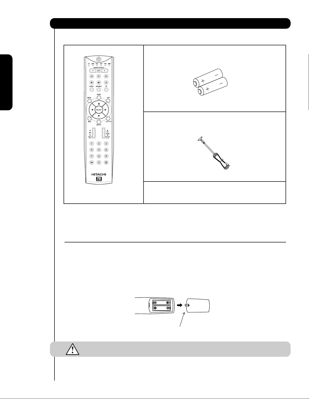
Remote Control Unit CLU-3851WL
(Part No. HL02065).
Two “AA” size, 1.5V batteries (P# FQ00021).
Two IR Mouse cables (P# EY01641).
REMOTE CONTROL BATTERY INSTALLATION AND REPLACEMENT
1. Open the battery cover of the remote control by pushing down and sliding the back cover off.
2. Insert two new “AA” size batteries for the remote control. When replacing old batteries, push them towards the
springs and lift them out.
3. Match the batteries to the (+) and (-) marks in the battery compartment.
4. Replace the cover.
CAUTION: Do not insert batteries with the ‘+’and ‘-’ polarities reversed as this may cause the
batteries to swell or rupture resulting in leakage.
Remote Control
Two “AA” size,
1.5V batteries
BOTTOM VIEW
(Remote Control)
Press down and slide back to remove.
IR Mouse Cable
For U.S. models:
For optional accessories, please access our web site at:
www.hitachi.us/tv
/
Page 5
5
How to set up your new HITACHI Projection Television
ANTENNA
Unless your LCD Rear PTV is connected to a cable TV system or to a centralized antenna system, a good outdoor
TV antenna is recommended for best performance. However, if you are located in an exceptionally good signal
area that is free from interference and multiple image ghosts, an indoor antenna may be sufficient.
LOCATION
Select an area where sunlight or bright indoor illumination will not fall directly on the picture screen. Also, be sure
that the location selected allows a free flow of air to and from the perforated back cover of the set. To avoid
cabinet warping, cabinet color changes, and increased chance of set failure, do not place the TV where
temperatures can become excessively hot, for example, in direct sunlight or near a heating appliance, etc. When
using your LCD Rear PTV against a wall, keep it at least 10cm (4 inches) from the wall.
NOTE: Your new HDTV has a built-in high definition television signal processor. This television includes a fan
to cool the processor. The sound of moving air from the fan is normal and may be noticeable in very
quiet environments.
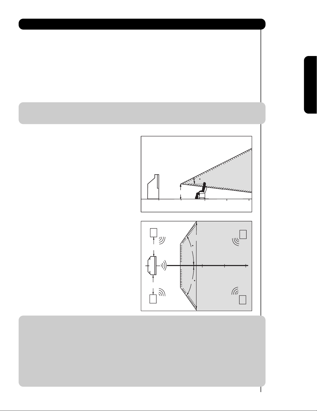
VIEWING
The major benefit of the HITACHI LCD Rear PTV is its
large viewing screen. To see this large screen at its best,
test various locations in the room to find the optimum
spot for viewing.
The best picture is seen by sitting directly in front of the
TV and about 10 to 18 feet from the screen. Picture
brightness decreases as the viewer moves to the left
and right of the receiver.
During daylight hours, reflections from outside light may
appear on the screen. If so, drapes or screens can be
used to reduce the reflection or the TV can be located in
a different section of the room.
If the TV’s audio output will be connected to a Hi-Fi
system’s external speakers, the best audio performance
will be obtained by placing the speakers equidistant
from each side of the receiver cabinet and as close as
possible to the height of the picture screen center. For
best stereo separation, place the external speakers at
least four feet from the side of the TV, place the
surround speakers to the side or behind the viewing
area. Differences in room sizes and acoustical
environments will require some experimentation with
speaker placement for best performance.
IMPORTANT NOTES:
1. Since LCD Rear PTV incorporates a high pressure lamp to display an image, it may take about one
minute for the picture to become stable, after the power has been turned on. After extended use, the
picture may darken, the color may look unusual, or the lamp “goes out,” (burns out). You may hear a
“pop” sound when the lamp “goes out.” These are common characteristics of the lamp, and should
not be considered defective.
2. LCD Rear PTV incorporates an advanced cooling fan system to prevent from overheating. If you hear
the cooling fan, it should not be considered defective.
3. If you hear a “cracking” sound from the TV cabinet, it is due to the TV’s cabinet expanding and
contracting due to room temperature changes. It has no effect on the TV’s functions.
4. The LCD Rear PTV cabinet is constructed with all plastic. Make sure to place it on a flat surface. An
uneven surface might warp the cabinet and reduce the picture quality.
First time use
20
BEST
VERTICAL VIEWING
ANGLE
3'
0'
5'
10'
15'
R
4" Minimum
20'
50
BEST
HORIZONTAL
4" Minimum
L
5'
10'
VIEWING ANGLE
50
15'
20'
S
20'
S
Page 6
6
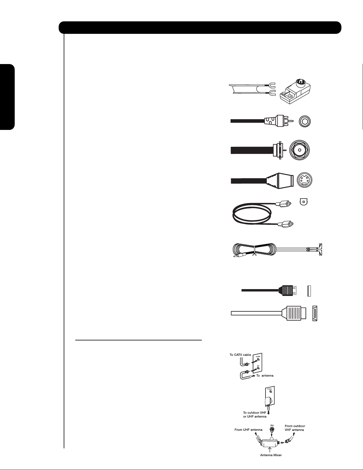
Most video/audio connections between components can be made with shielded video and audio cables that have
phono connectors. For best performance, video cables should use 75-Ohm coaxial shielded wire. Cables can be
purchased from most stores that sell audio/video products. Below are illustrations and names of common
connectors. Before purchasing any cables, be sure of the output and input connector types required by the
various components and the length of each cable.
300-Ohm Twin Lead Connector
This outdoor antenna cable must be connected to an
antenna adapter (300-Ohm to 75-Ohm).
Phono Connector
Used on all standard video and audio cables which
connect to inputs and outputs located on the
television’s rear jack panel and side control panel.
“F” Type 75-Ohm Coaxial Antenna Connector
For connecting RF signals (antenna or cable TV) to the
antenna jack on the television.
S-Video (Super Video) Connector
This connector is used on camcorders, VCRs and laserdisc players with an S-Video feature in place of the
standard video cable to produce a high quality picture.
Optical Cable
This cable is used to connect to an audio amplifier with
an Optical Audio In jack. Use this cable for the best
sound quality.
IR Mouse Cable/G-LINK Cable (Provided)
Connect the IR Mouse to the IR Blaster output of your
LCD Television when A/V Network is used. You must
place the IR Mouse in front of the corresponding IR
window of your cable box and VCR. This connection
allows your TV, and the TV Guide On Screen
TM
system,
to control your cable box and/or VCR.
USB Cable
This cable is used to connect your digital camera to the
Photo Input in the side of the LCD television.
HDMI Cable
This cable is used to connect your external devices
such as Set-Top-Boxes or DVD players equipped with
an HDMI output connection to the TV’s HDMI input.
ANTENNA CONNECTIONS TO REAR JACK PANEL
VHF (75-Ohm) antenna/CATV (Cable TV)
When using a 75-Ohm coaxial cable system, connect
CATV coaxial cable to the CABLE (75-Ohm) terminal. If
you have an antenna, connect the coaxial cable to the
AIR terminal.
VHF (300-Ohm) antenna/UHF antenna
When using a 300-Ohm twin lead from an outdoor
antenna, connect the VHF or UHF antenna leads to
screws of the VHF or UHF adapter. Plug the adapter
into the antenna terminal on the TV.
When both VHF and UHF antennas are
connected
Attach an optional antenna cable mixer to the TV
antenna terminal, and connect the cables to the
antenna mixer. Consult your dealer or service store for
the antenna mixer.
Hook-up Cables and Connectors
First time use
Page 7
7
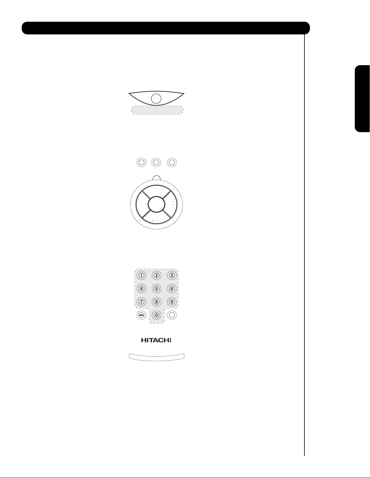
Quick Reference Remote Control Buttons and Functions
First time use
Page 8
8
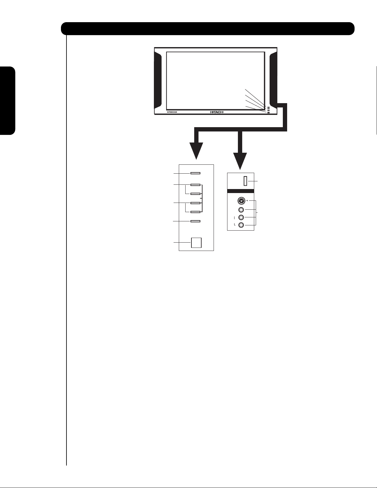
Front Panel Controls
First time use
MENU/SELECT button
This button allows you to enter the MENU, making it possible to set TV features to your preference without
using the remote. This button also serves as the SELECT button when in MENU mode.
INPUT/EXIT button
Press this button to display the input menu, CABLE, AIR, INPUT: 1, 2, 3, 4 and 5. This button also serves as
the EXIT button when in MENU mode.
CHANNEL selector
Press these buttons until the desired channel appears in the top right corner of the TV screen. These buttons
also serve as the cursor down (
) and up () buttons when in MENU mode.
VOLUME level
Press these buttons for your desired sound level. The volume level will be displayed on the TV screen. These
buttons also serve as the cursor left (
) and right () buttons when in MENU mode. When the TV power is
turned OFF at a volume level 31 or greater, the volume level will default to 30 when the TV is turned ON.
However, if it is set to a level 30 or less, the volume level will be at the level it was set when the TV is turned
ON.
POWER button
Press this button to turn the TV on or off.
SIDE INPUT JACKS (INPUT 5)
Use these audio/video jacks for a quick hook-up from a camcorder or VCR to instantly view your favorite
show or new recording. Press the INPUT button and select INPUT 5. If you have mono sound, insert the
audio cable into the left audio jack.
LEARNING AV NET Sensor
Point your equipment’s remote control at this area while using the AV NET Learning Wizard.
IR RECEIVER Sensor
Point the remote control at this area when selecting channels, adjusting volume, etc.
Lamp
Temp
Power
MENU/SELECT
CHANNEL
CURSOR
VOLUME
INPUT/EXIT
POWER
PHOTO
INPUT
VIDEO
L/MONO
AUDIO
INPUT 5
S-VIDEO
R
Page 9
9
Front Panel Controls
First time use
POWER Light
This light is on during normal operation. Light Blinking Slowly (2 seconds): television lamp is cooling down.
It takes 12-15 seconds to warm up and about 2 minutes to cool down.
TEMP Indicator
This light is off during normal operation. If this indicator is lit, the optic unit is too hot. If this indicator is
blinking, the cooling fan has stopped. Please call service. The optic unit has an air filter that may become
clogged over time. The ternal termperature will increse which will trigger the temperature sensor to display an
On-Screen warning. After 5 minutes, the lamp will turn off, then the TV will turn off with the TEMP LED On.
LAMP Indicator
This light is off during normal operation. If light is lit, the lamp has failed. See page 89-92 for lamp
replacement procedure. Consult your Hitachi dealer for proper part. If light is blinking, lamp cover is not
assembled securely after replacement.
PHOTO INPUT
Insert USB cable from your digital camera, USB memory or memory card USB drive to view your digital
still pictures (see page 25).
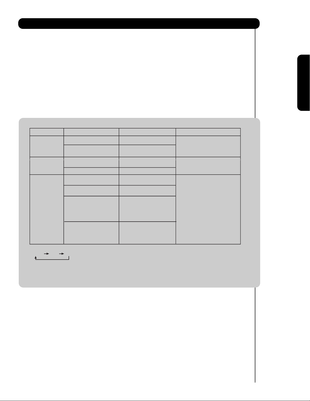
NOTES:
1.
INDICATOR INDICATION MEANING ACTION
LIGHT ON
LAMP LED
TEMP
LED
POWER
LED
2. If the LAMP, TEMP, and POWER LED are blinking in the order below, the television is warming up.
POWER TEMP LAMP
BLINKING
LIGHT ON
BLINKING
INTERMEDIATE BLINKING
(0.5 SEC CYCLE)
LIGHT ON
SHORT BLINKING
(0.3 SEC CYCLE)
LONG BLINKING
(1 SEC CYCLE)
NO LAMP LIGHT
or BROKEN LAMP
WRONG LAMP UNIT
ASSEMBLY / LAMP
DOOR OPEN
Too hot inside the
OPTIC unit
COOLING FAN STOPPED
BEGINNING OF WARM UP
AFTER THE POWER ON.
NORMAL OPERATION
BEGINNING OF COOL DOWN
(FOR 20 SEC.)
(TV CANNOT ACCEPT ANY CODE
IN THIS PERIOD EXCEPT WITHIN
THE BEGINNING 5 SEC.)
COOL DOWN
(FOR 6 MINUTES)
(TV CAN ACCEPT REMOTE
CONTROL AND SIDE BUTTONS)
Need to replace if
LAMP still does not light by
ìPower On ” again.
Check assembly condition of
LAMP UNIT
Call for Service
3. Your Hitachi LCD Rear Projection Television may appear to be OFF when it is set to input 1 ~ input 5 and the video
signal is not received from the input jacks. Please make sure the Blue Power light indicator is not lit (OFF) when
you are not watching for long lasting performance.
4. Your Hitachi LCD Rear Projection Television has an internal lamp that lights up the TV screen. Make sure to turn off
the Power when you do not watch the LCD Rear Projection Television for longer lamp life.
Page 10

10
First time use
Side Panel Jacks and Connections
The side panel jacks are provided as a convenience to allow you to easily connect a camcorder or VCR as shown
in the following examples:
NOTE: 1. Completely insert connection cord plugs when connecting to side panel jacks. If you do not, the
played back picture may be abnormal.
2. If you have a S-VHS VCR, use the S-INPUT cable in place of the standard video cable.
3. If you have a mono VCR, insert the audio cable into the left audio jack of your TV.
Page 11
11
First time use
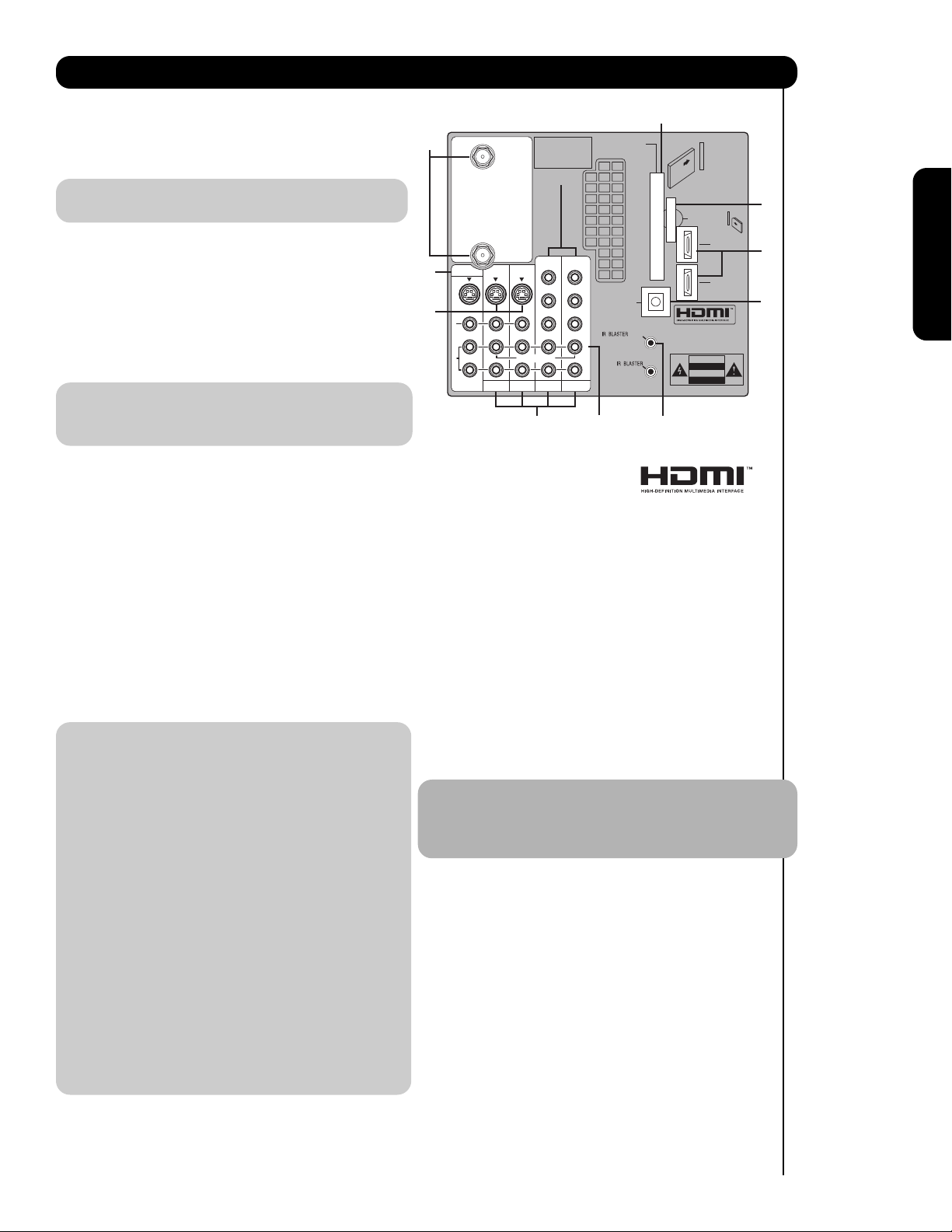
Rear Panel Connections
Antenna Input
CABLE – CATV (Cable TV) input.
AIR – RF antenna input.
NOTE: You may ask your local cable company
whether DTV services are available.
Audio/Video Inputs 1, 2, 3 and 4
By using the INPUTS button, CURSOR buttons
and SELECT button of the remote control you can
select each video source. Use the audio and video
inputs to connect external devices, such as VCRs,
camcorders, laserdisc players, DVD players etc. (If
you have mono sound, insert the audio cable into
the left audio jack.)
NOTE: You may use VIDEO or S-VIDEO inputs to
connect to INPUT 1 and 2, but only one of
these inputs may be used at a time.
Monitor Out
These jacks provide fixed or variable audio and video
signals which are used for recording. Use the S-Video
Output for high quality video output (see page 86).
S-Video Inputs 1 and 2
INPUTS 1 and 2 provide S-Video (Super Video)
jacks for connecting equipment with S-Video
output capability.
Component: Y-P
BPR Inputs
INPUTS 3 and 4 provide Y-P
BPR jacks for
connecting equipment with this capability, such as
a DVD player or Set Top Box. You may use
composite video signal for both inputs.
NOTE: 1. Do not connect composite VIDEO and
S-VIDEO to INPUT 1, 2 or 5 at the same
time. S-VIDEO has priority over VIDEO input.
2. Your component outputs may be labeled
Y, B-Y, and R-Y. In this case, connect the
components B-Y output to the TV’s P
B
input and the components R-Y output to
the TV’s P
R input.
3. Your component outputs may be labeled
Y-C
BCR. In this case, connect the component
C
B output to the TV’s PB input and the
component C
R output to the TV’s PR input.
4. It may be necessary to adjust TINT to
obtain optimum picture quality when using
the Y-P
BPR inputs (see page 41).
5. To ensure no copyright infringement, the
MONITOR OUT output will be abnormal,
when using the Y-P
BPR jacks.
6. INPUT 3 and INPUT 4 (Y/VIDEO) can be
used for composite video and component
video input.
HDMI (High Definition Multimedia Interface)
(INPUTS 1 and 2)
ABOUT HDMI – HDMI is the
next-generation all digital interface for consumer
electronics. HDMI enables the secure distribution
of high-definition video and multi-channel audio in
a single cable. Because digital television (DTV)
signals remain in digital format, HDMI assures that
pristine high-definition images retain the highest
video quality from the source all the way to your
television screen.
Use the HDMI input for your external devices such
as Set-Top-Boxes or DVD players equipped with an
HDMI output connection.
HDMI, the HDMI logo and High-Definition
Multimedia Interface are trademarks or registered
trademarks of HDMI Licensing LLC.
NOTE: 1. The HDMI input is not intended for use
with personal computers.
2. Only DTV formats such as 1080i, 720p, 480i
and 480p are available for HDMI INPUTS.
Optical Out (Digital Audio)
This jack provides Digital Audio Output for your
audio device that is Dolby
®
Digital and PCM
compatible, such as an audio amplifier.
Manufactured under license from Dolby
Laboratories. “DOLBY” and the DOUBLE-D
symbol are trademarks of Dolby Laboratories.
Upgrade Card
This card slot is for future software upgrades.
Hitachi will notify you if a software upgrade is
required for your TV. In order to receive written
notification, please complete and return your
warranty card.
Apparatus Claims of U.S.
CABLE
Patent Nos. 4,631,603;
4,577,216; 4,819,098;
4,907,093; and 6,381,747
licensed for limited
viewing uses only.
CableCARD™
(Top of card faces right)
Top faces
Upgrade Card
AIR
MONITOR OUT
쐋
S
I
V
I
D
E
O
V
I
D
E
O
A
U
D
I
O
AUDIO
TO HI-FI
INPUT 1
TV AS CENTER
INPUT 2
Y/
VIDEO
P
P
B
B
P
P
R
R
INPUT 3 INPUT 4
Y/
VIDEO
P
P
B
B
OPTICAL OUT
Digital Audio
P
P
R
R
/
(MONO)(MONO)(MONO)(MONO)
G-LINK
L
R
HDMI INPUT 1
HDMI INPUT 2
CAUTION
Page 12
12
First time use
TV AS CENTER (INPUTS 1-4)
These jacks are for stereo amplifiers with center
signal output capability. This feature allows the TV
speakers to be used as a center speaker. The TV
must be set as a center channel by selecting TV
AS CENTER on the Internal Speakers Settings of
the Audio Menu (see page 45).
IR Blaster/G-LINK
This jack provides IR output to your external
components (VCR, Cable box, DVD player, etc.).
With this connection, your external components
can automatically be controlled by the A/V network
feature. This connection will allow you to control
the external components with your LCD Television’s
remote control in TV mode. The G-LINK
connection will enable the TV Guide On Screen
TM
recording feature.
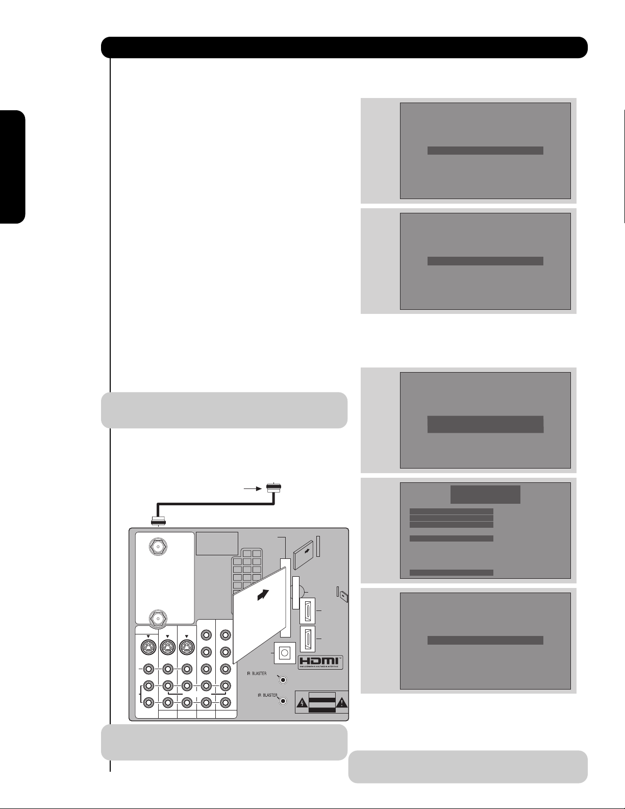
CableCARD Slot
This slot is for the CableCARD that will be provided
by your local cable operator to gain access to
chosen cable channels. The CableCARD will allow
you to tune digital and high definition cable
channels. Please call your local cable operator if
this service is available before requesting a
CableCARD (also known as Point of Deployment
(POD) module).
IMPORTANT: Please read the “Lamp Power
Control” feature on page 75 before installing the
CableCARD.
1. Connect a coaxial cable to cable terminal of the
Rear Panel Jacks.
2. Insert the CableCARD into the slot (Top of card
should be facing right as shown below).
NOTE: 1. A digital cable subscription is required.
2. Do not insert a PCMCIA card into the
CableCARD slot.
If the CableCARD is properly installed or not installed,
the TV will display the following respective screens.
After the CableCARD is installed, wait until the second
screen below appears. The third screen below will
appear if a channel is not authorized for viewing. Press
the EXIT button to exit the second screen.
Please take note of all information on the screen (you
will provide this information to your cable operator).
Call your cable operator and give them the information
from the card to start your cable service.
NOTE: Please see Appendix E on page 100 for
additional CableCARD information.
Rear Panel Connections
R
L
A
U
D
I
O
V
I
D
E
O
S
I
V
I
D
E
O
(MONO)(MONO)(MONO)(MONO)
P
R
P
B
Y/
VIDEO
Y/
VIDEO
P
R
P
B
P
R
P
B
P
R
P
B
MONITOR OUT
AUDIO
TO HI-FI
INPUT 1
CABLE
AIR
INPUT 2
TV AS CENTER
INPUT 3 INPUT 4
CableCARD™
CAUTION
(Top of card faces right)
Top faces
OPTICAL OUT
Digital Audio
Upgrade Card
HDMI INPUT 1
Apparatus Claims of U.S.
Patent Nos. 4,631,603;
4,577,216; 4,819,098;
4,907,093; and 6,381,747
licensed for limited
viewing uses only.
Digital Cable
CableCARD™
Top faces this
way
HDMI INPUT 2
G-LINK
/
CableCARD is installed
OR
CableCARD is not installed
Acquiring Data.
Please wait.
In order to start cable service
for this device, please contact
your cable provider
CableCARD(tm): 123-456-789-1
Host: 123-456-789-1
Data: 123-456-789-1
Unit Address: 123-456-789-1
Press EXIT to return
OR
Not an Authorized Channel
Page 13
13
First time use
TIPS ON REAR PANEL CONNECTIONS
• S-VIDEO, Y- P
BPR and HDMI
connections are provided for
high performance laserdisc
players, VCRs etc. that have
this feature. Use these
connections in place of the
standard video connection if
your device has this feature.
• If your device has only one
audio output (mono sound),
connect it to the left audio jack
on the television.
• Refer to the operating guide of
your other electronic equipment
for additional information on
connecting your hook-up
cables.
• A single VCR can be used for
VCR #1 and VCR #2, but note
that a VCR cannot record
its own video or line output
(INPUT 1 in the example on
this page). Refer to your VCR
operating guide for more
information on line input-output
connections.
• You may use VIDEO or
S-VIDEO inputs to connect to
INPUT 1, INPUT 2 or INPUT 5,
but only one of these may be
used at a time.
• Connect only one component
(VCR, DVD player, camcorder,
etc.) to each input jack.
• COMPONENT: Y- P
BPR (INPUT 3 and INPUT 4)
connections are provided for high performance
components, such as DVD players and set-topboxes. Use these connections in place of the
standard video connection if your device has this
feature. INPUT 3 and INPUT 4 accepts both
composite and component video signals.
• Your component outputs may be labeled Y, B-Y,
and R-Y. In this case, connect the components
B-Y output to the TV’s P
B input and the
components R-Y output to the TV’s P
R input.
• Your component outputs may be labeled Y- C
BCR.
In this case, connect the components C
B output to
the TV’s P
B input and the components CR output to
the TV’s P
R input.
• You may use composite and component video
signals for INPUT 3 and INPUT 4.
• It may be necessary to adjust TINT to obtain
optimum picture quality when using the Y- P
BPR
inputs (see page 41).
• To ensure no copyright infringement, the
MONITOR OUT output may be abnormal, when
using the Y- P
BPR jacks.
• When using an HDMI input from a Set-Top-Box, it
is recommended that a 1080i or 720p input signal
is used.
NOTE: 1. Connect only one component to each
input jack.
2. Follow connections that pertain to your
personal entertainment system.
3. INPUT 3 and INPUT 4 can accomodate
Composite and Component video signals.
4. Cables are not included with the purchase
of this TV, except when noted as
“provided”.
MACROVISION NOTES:
1. Video signals fed through a VCR may be
affected by copyright protection systems
and the picture will be distorted on the
television.
2. Connecting the television directly to the
Audio /Video output of a Set-Top-Box will
assure a more normal picture.
Rear Panel Connections
MONITOR OUT
S
I
V
I
D
E
O
V
I
D
E
O
A
U
D
I
O
AUDIO
TO HI-FI
INPUT 1
CABLE
AIR
INPUT 2
Apparatus Claims of U.S.
Patent Nos. 4,631,603;
4,577,216; 4,819,098;
4,907,093; and 6,381,747
licensed for limited
viewing uses only.
Y/
VIDEO
TV AS CENTER
INPUT 3 INPUT 4
Outside Antenna
or Digital Cable
CableCARD™
(Top of card faces right)
Top faces
Upgrade Card
HDMI INPUT 1
Y/
VIDEO
P
P
P
P
B
B
B
B
P
P
R
R
OPTICAL OUT
Digital Audio
P
P
R
R
(MONO)(MONO)(MONO)(MONO)
L
R
CAUTION
Page 14
14
First time use
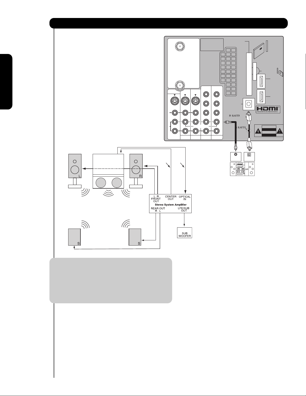
Match the numbers below to the diagram for
speaker placement.
The television’s internal speakers will act as
center speaker (select AUDIO - INTERNAL
SPEAKERS - TV AS CENTER).
These FRONT left and right speakers are
connected to the FRONT output of a
separate audio amplifier.
These REAR left and right speakers are
connected to the Rear output of a separate
audio amplifier.
This subwoofer is connected to the LFE/SUB
Out output of a separate audio amplifier.
NOTE: 1. The Optical Out (Digital Audio) provides a
fixed digital audio output to your external
component such as an A/V receiver with
optical input capability. The audio level
can only be controlled through the volume
control of the external audio amplifier.
2. See page 46 for AUDIO-Digital Output.
Connecting External Audio Sources
MONITOR OUT
S
I
RCA
Cable
V
I
D
E
O
V
I
D
E
O
A
U
D
I
O
AUDIO
TO HI-FI
Optical
Cable
INPUT 1
CABLE
AIR
INPUT 2
Apparatus Claims of U.S.
Patent Nos. 4,631,603;
4,577,216; 4,819,098;
4,907,093; and 6,381,747
licensed for limited
viewing uses only.
Y/
VIDEO
TV AS CENTER
INPUT 3 INPUT 4
CableCARD™
(Top of card faces right)
Top faces
Upgrade Card
HDMI INPUT 1
Y/
VIDEO
P
P
P
P
B
B
B
B
P
P
R
R
OPTICAL OUT
Digital Audio
P
P
R
R
/
(MONO)(MONO)(MONO)(MONO)
L
R
G-LINK
CENTER
OPTICAL
OUT
IN
Stereo System Amplifier
or DVD Player
HDMI INPUT 2
CAUTION
쐋쐋
Page 15
15
First time use
BEFORE OPERATING
EXTERNAL VIDEO SOURCE
Connect an external source to the INPUT terminal, then
press the INPUTS button to show the INPUTS menu.
Use the CURSOR PAD to select the CABLE, AIR or
INPUT of your choice. Then press the SELECT button
to confirm your choice (see page 24).
NOTE: When the TV is set to VIDEO and a video
signal is not received from the VIDEO INPUT
JACK on the back panel of the TV (i.e.,
VCR/laserdisc player, etc. is not connected or
the video device is OFF), the set will appear
to be OFF.
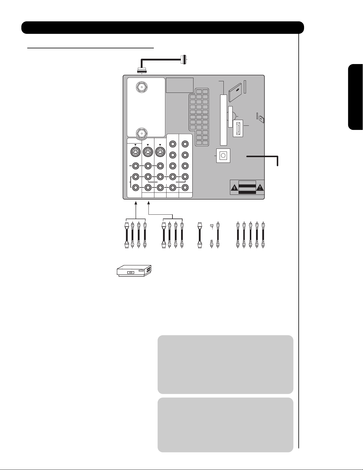
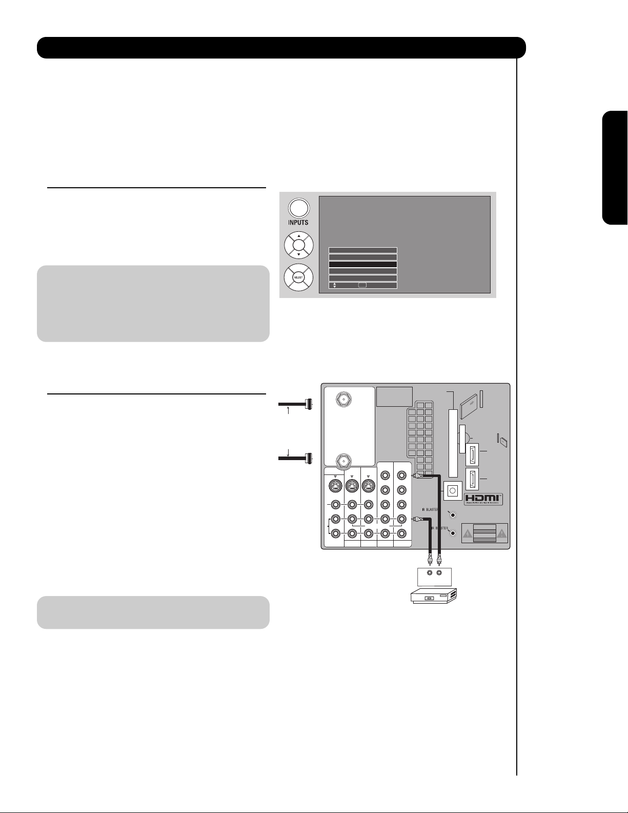
CONNECTING A COMPOSITE VIDEO AND
MONAURAL AUDIO SOURCE TO INPUT1 –
INPUT5
1. Connect the cable from the VIDEO OUT of the VCR
or the laserdisc player to the INPUT (VIDEO) jack,
as shown on the TV set on the right.
2. Connect the cable from the AUDIO OUT of the
VCR or the laserdisc player to the INPUT
(MONO)/L(AUDIO) jack.
3. Press the INPUTS button, then select INPUT 4
from the INPUTS menu to view the program from
the VCR or the laserdisc player. The VIDEO OSD
label disappears automatically after approximately
four seconds.
4. Select CABLE from the INPUTS menu to return to
the last channel tuned.
NOTE: The INPUT 3 can be used in the same
manner as INPUT 4.
The exact arrangement you use to connect the VCR, camcorder, laserdisc player, DVD player, or HDTV Set Top
Box to your TV set is dependent on the model and features of each component. Check the owner’s manual of
each component for the location of video and audio inputs and outputs.
The following connection diagrams are offered as suggestions. However, you may need to modify them to
accommodate your particular assortment of components and features. For best performance, video and audio
cables should be made from coaxial shielded wire.
Connecting External Video Sources
R
L
A
U
D
I
O
V
I
D
E
O
S
I
V
I
D
E
O
(MONO)(MONO)(MONO)(MONO)
P
R
P
B
Y/
VIDEO
Y/
VIDEO
P
R
P
B
P
R
P
B
P
R
P
B
MONITOR OUT
AUDIO
TO HI-FI
INPUT 1
CABLE
AIR
INPUT 2
TV AS CENTER
INPUT 3 INPUT 4
CableCARD™
CAUTION
(Top of card faces right)
Top faces
OPTICAL OUT
Digital Audio
Upgrade Card
HDMI INPUT 1
Apparatus Claims of U.S.
Patent Nos. 4,631,603;
4,577,216; 4,819,098;
4,907,093; and 6,381,747
licensed for limited
viewing uses only.
Audio Video
VCR
OUTPUT
HDMI INPUT 2
Connect the
Cable and/or
Air cables
G-LINK
/
Input 5
Photo Input
Cable
Air
Input 1
Move SEL Sel.
Page 16
16
First time use
Connecting External Video Sources
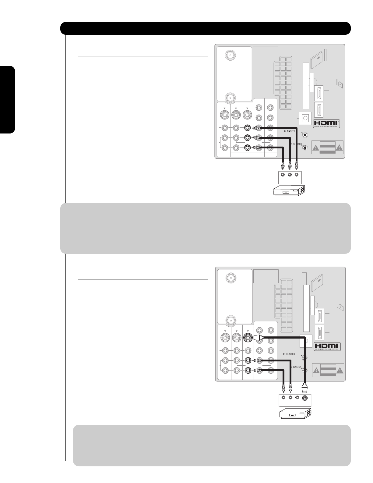
CONNECTING A COMPOSITE VIDEO AND
STEREO AUDIO SOURCE TO INPUT1 – INPUT5
1. Connect the cable from the VIDEO OUT of the VCR
or the laserdisc player to the INPUT (VIDEO) jack,
as shown on the TV set on the right.
2. Connect the cable from the AUDIO OUT R of the
VCR or the laserdisc player to the INPUT
(AUDIO/R) jack.
3. Connect the cable from the AUDIO OUT L of the
VCR or the laserdisc player to the INPUT (AUDIO/L)
jack.
4. Press the INPUTS button, then select INPUT 2
from the INPUTS menu to view the program from
the VCR or laserdisc player. The VIDEO OSD label
disappears automatically after approximately four
seconds.
5. Select CABLE from the INPUTS menu to return to
the last channel tuned.
NOTE: 1. Completely insert the connection cord plugs when connecting to rear panel jacks. The picture and
sound that is played back will be abnormal if the connection is loose.
2. A single VCR can be used for VCR #1 and VCR #2 (see page 13), but note that a VCR cannot record
its own video or line output. Refer to your VCR operating guide for more information on line inputoutput connections.
3. When INPUT 3 or 4 are used, it’s necessary to connect the video output from the device to the
Y/Video input jack of the TV.
CONNECTING AN S-VIDEO
SOURCE TO INPUT 1, 2 AND 5
1. Connect the cable from the S-VIDEO OUT of the
VCR or the laserdisc player to the INPUT (S-VIDEO)
jack, as shown on the TV set on the right.
2. Connect the cable from the AUDIO OUT R of the
VCR or the laserdisc player to the INPUT
(AUDIO/R) jack.
3. Connect the cable from the AUDIO OUT L of the
VCR or the laserdisc player to the INPUT (AUDIO/L)
jack.
4. Press the INPUTS button, then select INPUT 2
from the INPUTS menu to view the program from
the VCR or laserdisc player. The VIDEO OSD label
disappears automatically after approximately four
seconds.
5. Select CABLE from the INPUTS menu to return to
the last channel tuned.
NOTE: 1. Completely insert the connection cord plugs when connecting to rear panel jacks. The picture and
sound that is played back will be abnormal if the connection is loose.
2. A single VCR can be used for VCR #1 and VCR #2 (see page 13), but note that a VCR cannot record
its own video or line output. Refer to your VCR operating guide for more information on line inputoutput connections.
CABLE
Apparatus Claims of U.S.
Patent Nos. 4,631,603;
4,577,216; 4,819,098;
4,907,093; and 6,381,747
licensed for limited
viewing uses only.
CableCARD™
(Top of card faces right)
Top faces
MONITOR OUT
S
I
V
I
D
E
O
V
I
D
E
O
A
U
D
I
O
AUDIO
TO HI-FI
INPUT 1
AIR
TV AS CENTER
INPUT 2
Y/
Y/
VIDEO
VIDEO
P
P
P
P
B
B
B
B
P
P
P
P
R
R
R
R
(MONO)(MONO)(MONO)(MONO)
INPUT 3 INPUT 4
OPTICAL OUT
Digital Audio
L
R
/
G-LINK
Upgrade Card
HDMI INPUT 1
HDMI INPUT 2
CAUTION
OUTPUT
VLR
VCR
CABLE
Apparatus Claims of U.S.
Patent Nos. 4,631,603;
4,577,216; 4,819,098;
4,907,093; and 6,381,747
licensed for limited
viewing uses only.
CableCARD™
(Top of card faces right)
MONITOR OUT
S
I
V
I
D
E
O
V
I
D
E
O
A
U
D
I
O
AUDIO
TO HI-FI
INPUT 1
AIR
TV AS CENTER
INPUT 2
Y/
Y/
VIDEO
VIDEO
P
P
P
P
B
B
B
B
P
P
P
P
R
R
R
R
(MONO)(MONO)(MONO)(MONO)
INPUT 3 INPUT 4
OPTICAL OUT
Digital Audio
L
R
/
G-LINK
LR
OUTPUT
V
S-VIDEO
VCR
Top faces
Upgrade Card
HDMI INPUT 1
HDMI INPUT 2
CAUTION
Page 17
17
First time use
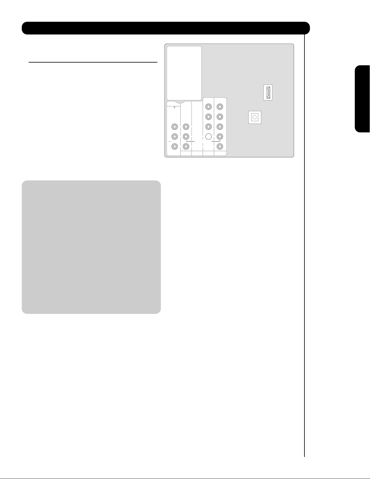
CONNECTING A COMPONENT SOURCE WITH
HDMI OR DVI CAPABILITY TO INPUT 1 OR
INPUT 2
1. Connect the HDMI or DVI to HDMI connection
cable from the output of the HDTV set top box or
DVD player to the HDMI input as shown on the TV
set on the right. When using a component with DVI
output, you also have to connect the AUDIO OUT
(R/L) of the component to the AUDIO IN (R/L) of
INPUT 1 or INPUT 2.
2. Press the INPUTS button, then select INPUT 1 or
INPUT 2 from the INPUTS menu to view the
program from the HDTV set top box or DVD player.
The VIDEO OSD label disappears automatically
after approximately four seconds.
3. Select CABLE from the INPUTS menu to return to
the last channel tuned.
NOTE: 1. Completely insert the connection cord
plugs when connecting to rear panel jacks.
The picture and sound that is played back
will be abnormal if the connection is loose.
2. The HDMI input on INPUT 1 or 2 contains
the copy protection system called Highbandwidth Digital Content Protection
(HDCP). HDCP is a cryptographic system
that encrypts video signals when using
HDMI connections to prevent illegal
copying of video contents.
3. HDMI is not a “NETWORK” technology. It
establishes a one-way point-to-point
connection for delivery of uncompressed
video to a display.
4. The connected digital output device
controls the HDMI interface so proper setup of device user settings determines final
video appearance.
Connecting External Video Sources
Page 18
18
First time use
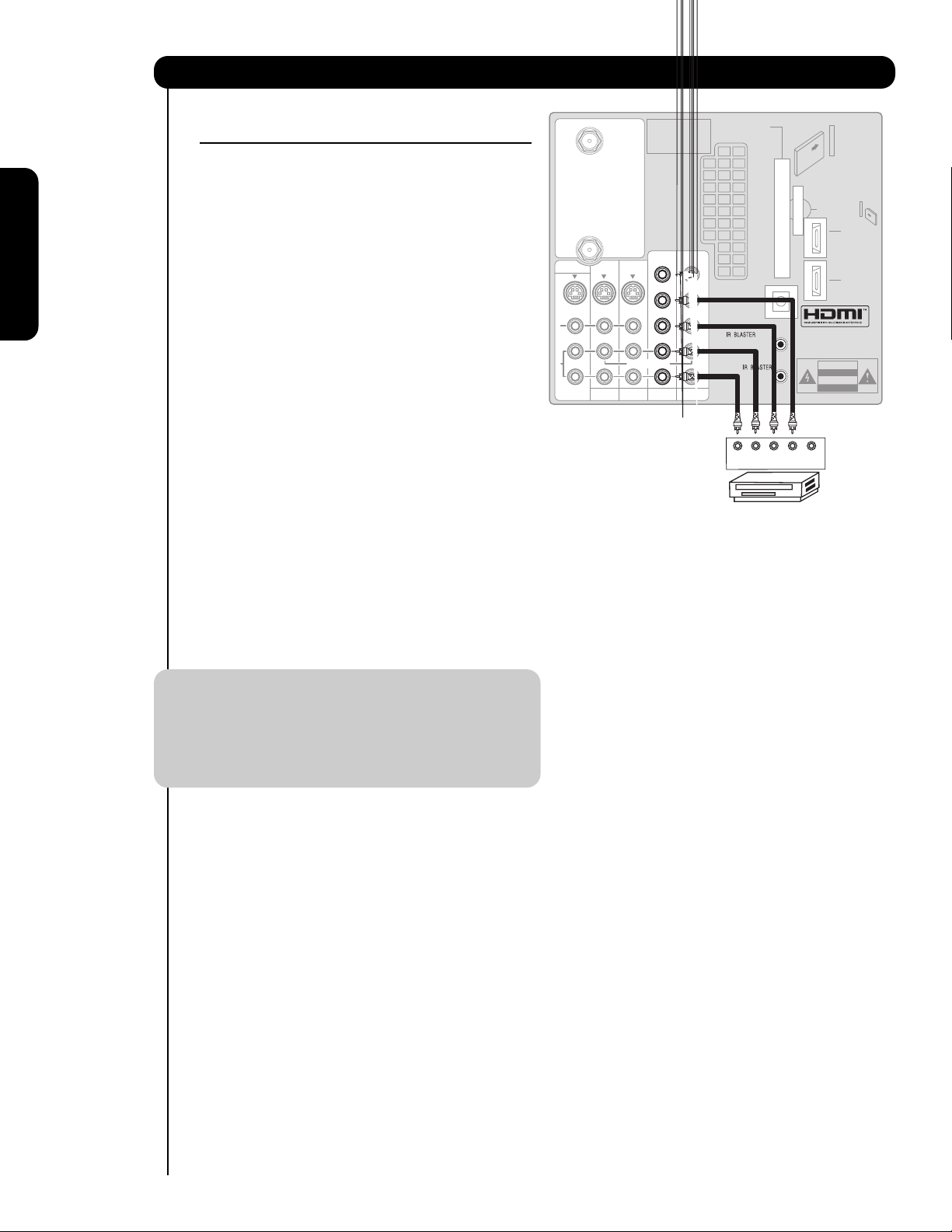
CONNECTING A COMPONENT
SOURCE TO INPUT 3 OR 4: Y-PBPR.
1. Connect the cable from the Y OUT of the
Laserdisc/DVD player or HDTV set top box to the
INPUT (Y) jack, as shown on the TV set on the
right.
2. Connect the cable from the C
B/PB OUT or B-Y OUT
of the Laserdisc/DVD player or HDTV set top box
to the INPUT (P
B) jack.
3. Connect the cable from the C
R/PR OUT or R-Y OUT
of the laserdisc/DVD player or HDTV set top box to
the INPUT (P
R) jack.
4. Connect the cable from the AUDIO OUT R of the
Laserdisc/DVD player or HDTV set top box to the
INPUT (AUDIO/R) jack.
5. Connect the cable from the AUDIO OUT L of the
Laserdisc/DVD player or HDTV set top box to the
INPUT (AUDIO/L) jack.
6. Press the the INPUTS button, then select INPUT 3
from the INPUTS menu to view the program from
the Laserdisc/DVD player or HDTV set top box. The
VIDEO OSD label disappears automatically after
approximately four seconds.
7. Select CABLE from the INPUTS menu to return to
the last channel tuned.
NOTE: 1. Completely insert the connection cord
plugs when connecting to rear panel jacks.
The picture and sound that is played back
will be abnormal if the connection is loose.
2. See page 13 for tips on REAR PANEL
CONNECTIONS.
Connecting External Video Sources
MONITOR OUT
S
I
V
I
D
E
O
V
I
D
E
O
A
U
D
I
O
AUDIO
TO HI-FI
INPUT 1
CABLE
AIR
TV AS CENTER
INPUT 2
Apparatus Claims of U.S.
Patent Nos. 4,631,603;
4,577,216; 4,819,098;
4,907,093; and 6,381,747
licensed for limited
viewing uses only.
Y/
Y/
VIDEO
VIDEO
P
P
P
P
B
B
B
B
P
P
P
P
R
R
R
R
(MONO)(MONO)(MONO)(MONO)
INPUT 3 INPUT 4
OPTICAL OUT
Digital Audio
L
R
CableCARD™
(Top of card faces right)
/
G-LINK
OUTPUT
DVD Player
Top faces
Upgrade Card
HDMI INPUT 1
HDMI INPUT 2
CAUTION
PR PB YLR
Page 19
19
Connecting External Video Sources
First time use
Your HITACHI LCD Rear Projection Television is equipped with an AV Network feature. This feature helps to
control your external Audio/Video equipment (VCR, Set Top Box, DVD, etc.). Once this is setup, it allows
your IR Mouse connector to control your equipment using your HITACHI LCD Rear PTV Remote Control.
You can use your HITACHI remote control to control the Audio/Video equipment command without the
equipment’s remote control.
The LCD Rear PTV Rear Panel has 2 IR BLASTER jacks. Each IR Mouse cable can connect up to 2
external Audio/Video components. Therefore, you can connect the LCD Rear PTV with up to four
components. Please see the following example of an AV Network setup between your HITACHI LCD Rear
PTV and external Audio/Video equipment (VCR and DVD Player).
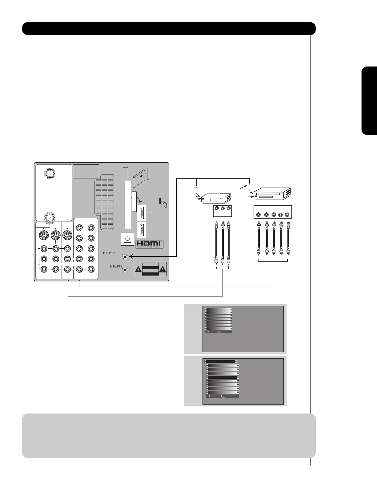
CONNECTING EXTERNAL AUDIO/VIDEO COMPONENTS TO IR BLASTER FOR AV NETWORK
1. Connect your external Audio/Video components to the Rear Panel shown below.
2. Connect the IR Mouse cable to the IR BLASTER output of the Rear Panel.
3. Place the IR Mouse in front of the infrared sensor of the external components you wish to control.
NOTE: 1. The Rear Panel has two IR BLASTER outputs which can control up to a total of four external
components.
2. The IR Mouse must be placed in front of the external components infrared sensor for the AV
Network to work. Double-sided mounting tape may be used to hold the IR Mouse in place.
3. The correct codes must be chosen for each of the Audio/Video components for the AV Network to
function properly.
4. ACCESS THE AV NET SETUP WIZARD
Press the MENU button.
5. Use the CURSOR PAD or channel scroll down
to highlight SETUP.
6. Press the SELECT or CURSOR PAD button to
select.
7. Use the CURSOR PAD or channel scroll to
highlight the SET AV NET features then press the
SELECT button.
8. Follow the Setup procedure on pages 76-83.
Apparatus Claims of U.S.
MONITOR OUT
S
I
V
I
D
E
O
V
I
D
E
O
A
U
D
I
O
AUDIO
TO HI-FI
INPUT 1
CABLE
AIR
INPUT 2
Patent Nos. 4,631,603;
4,577,216; 4,819,098;
4,907,093; and 6,381,747
licensed for limited
viewing uses only.
Y/
VIDEO
TV AS CENTER
INPUT 3 INPUT 4
P
P
B
B
P
P
R
R
(MONO)(MONO)(MONO)(MONO)
Y/
VIDEO
P
P
B
B
P
P
R
R
OPTICAL OUT
Digital Audio
L
R
CableCARD™
(Top of card faces right)
/
G-LINK
Top faces
Upgrade Card
CAUTION
HDMI INPUT 1
HDMI INPUT 2
Infrared
Sensor
VCR
V L R
OUTPUT
IR
Mouse
Infrared
Sensor
DVD Player
YP
OUTPUT
B/CBPR/CR
R L
Video
Audio
TV Guide On Screen
Channel Manager
Locks
Timers
Setup
Move SEL Select
Setup
Menu Preference
Lamp Power Control
Set The Inputs
Set AV NET
Set Closed Captions
Set Monitor Out
Upgrades
Quick Start Up
Move SEL Set
Page 20
20
Connecting External Video Sources
First time use
Your HITACHI LCD Rear Projection Television is equipped with a G-LINK feature. This connection is
necessary for the TV Guide On Screen
TM
system to work with your cable box to receive program listings and
to enable VCR recording features. Once you setup the G-LINK (IR Mouse) connector, then you can use
your HITACHI LCD Rear PTV Remote Control and the TV Guide On Screen system to control your cable box
and VCR recording features.
The LCD Rear PTV Rear Panel has 2 IR BLASTER jacks. One IR Mouse cable can connect up to 2 external
Audio/Video components. Please see the following example of a G-LINK setup between your HITACHI LCD
Rear PTV and external Audio/Video equipment (VCR and Cable box).
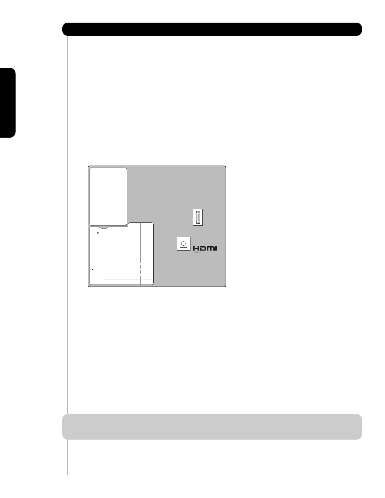
CONNECTING THE CABLE BOX/VCR TO G-LINK FOR TV GUIDE ON SCREEN
TM
SYSTEM
1. Connect your external Audio/Video components to the Rear Panel shown below.
2. Connect the IR Mouse cable to the IR BLASTER/G-LINK output of the Rear Panel.
3. Place the IR Mouse in front of the infrared sensor of the external components you want to control.
NOTE: The IR Mouse must be placed in front of the external components infrared sensor for the AV
Network to work.
4. To access the TV Guide On-ScreenTMsystem,
press the MENU button.
5. Use the CURSOR PAD or channel scroll down
to highlight TV GUIDE ON SCREEN.
6. Press the SELECT or CURSOR PAD button to
select.
7. Follow the Setup procedure on pages 47-51.
Page 21

21
The Remote Control
The Remote Control
In addition to controlling all the functions on your
HITACHI LCD Rear Projection TV, the new remote
control is designed to operate different types of
VCRs, CATV (Cable TV) converters, set-top-box,
satellite receiver, DVD players, and other
audio/video equipment with one touch. Basic
operation keys are grouped together in one area.
To operate your LCD Rear Projection TV, point the
remote control at the remote sensor of the
television and select the TV by pressing the or
button of the Source Access on the remote. The
TV mode indicator will blink, indicating that the
remote will now control your television.
To operate your VCR, point the remote at the
remote sensor of the VCR and select PVR by
pressing the or button of the Source Access
on the remote. The PVR mode indicator will blink,
indicating that the remote will now control your
VCR (see page 34 for instructions on how to
program the remote to control your VCR).
To operate your PVR (Personal Video Recorder),
point the remote at the remote sensor of the PVR
and select PVR by pressing the or button of
the Source Access on the remote. The PVR mode
indicator will blink, indicating that the remote will
now control your PVR (see page 34 for instruction
on how to program the remote to control your
PVR).
To operate your cable box, point the remote at the
remote sensor of the cable box and select the
CABLE (CBL) by pressing the or button of the
Source Access on the remote. The CBL mode
indicator will blink, indicating that the remote will
now control your cable box (see page 31 for
instructions on how to program the remote to
control your cable box).
To operate your set-top-box or satellite receiver
point the remote at the remote sensor of the settop-box and select the SET-TOP-BOX (STB) by
pressing the or button of the Source Access
on the remote. If you have a satellite receiver, use
this button to program your satellite receiver. The
STB mode indicator will blink, indicating that the
remote will now control your set-top-box (see
page 32 for instructions on how to program the
remote to control your set-top-box).
To operate your DVD player, point the remote at
the remote sensor of the DVD player and select
DVD by pressing the or button of the Source
Access on the remote. The DVD mode indicator
will blink, indicating that the remote will now
control your DVD Player (see page 33 for
instruction on how to program the remote to
control your DVD
player).
To operate additional audio equipment, point the
remote at the remote sensor of the component you
wish to control and select AMP by pressing the
or button of the Source Access on the remote.
The AMP mode indicator will blink, indicating that
the remote will now control your audio equipment
(see page 35 for instructions on how to program
the remote to control additional Audio/Video
equipment).
NOTE: When you press any remote control button,
the buttons will light up. The illumination will
light a few seconds during this time. The
buttons will appear to light if the room is
dark.
There are two modes of lighting the Remote Control buttons.
They are the Automatic and Manual modes.
AUTOMATIC MODE (Default mode)
In Automatic mode, if any button is pressed (including the
LIGHT button), the illumination will light for 4 seconds.
MANUAL MODE (Optional mode)
In Manual mode, the illumination will only work when the
LIGHT button is pressed. When the LIGHT button is pressed,
the illumination will light for 8 seconds. During the illumination, if the LIGHT button is pressed, the illumination will turn
off.
CHANGING LIGHTING MODES (Automatic to
Manual/Manual to Automatic)
1. Place the Remote Control in TV Mode by using the
SOURCE ACCESS
and buttons. The TV mode
indicator will blink 3 times to confirm the remote control
mode.
2. Press and hold the LIGHT button for 10 seconds. After
releasing the LIGHT button, the TV mode indicator will
blink 3 times to confirm the mode switch.
A/V NET
/
Page 22

22
The Remote Control
How to Use the Remote to Control Your TV
POWER button
Press this button to turn the TV set on or off when
the remote is in TV mode. (See page 21 for
instructions on how to set the remote control to TV
mode.)
MODE Indicator
Turns on or blinks to show remote control mode.
햴 SOURCE ACCESS ( or ) buttons
Press these buttons to select remote control mode.
SOURCE ACCESS (ENT) button
Hold down this button while entering your device
code to program the remote (see pages 31-38).
You can also use this button in an optional Input
access feature (see page 36).
PAUSE button
Press the PAUSE button to freeze the picture.
Press the EXIT button to return the picture to
motion. Press the PAUSE button repeatedly to
cycle through the three different freeze modes (see
page 30).
Page 23

23
The Remote Control
How to Use the Remote to Control Your TV
ASPECT button
Press this button to quickly change the picture format ASPECT ratio. Depending on the input signal format
received, the picture format ratio allows you to adjust the images through the following options.
• Antenna-Analog
• S-Video/Video Input
(Auto Aspect: Off)
• HDMI-480i/480p Input
(Auto Aspect: Off)
• Component-480i/480p
Input (Auto Aspect: Off)
Note: Please see Appendix A
on page 99.
• Antenna-Digital (4:3)
• S-Video/Video 4:3/Letter
Input (Auto Aspect: On)
• HDMI-480i/480p 4:3/
Letter Input (Auto Aspect: On)
• Component-480i/480p 4:3/
Letter Input
(Auto Aspect: On)
Note: Please see Appendix B
on page 99.
• S-Video/Video 16:9 Input
(Auto Aspect: On)
• HDMI-480i/480p 16:9 Input
(Auto Aspect: On)
• Component-480i/480p
16:9 Input
(Auto Aspect: On)
Note: Please see Appendix C
on page 99.
• Antenna-Digital (16:9)
• HDMI-720p/1080i Input
• Component-720p/1080i
Input
Note: Please see Appendix D
on page 99.
NOTE: 1. The Aspect Style setting you select for an ANT input will automatically be set for the other ANT
input. However, all five video inputs have independent Aspect Style settings.
2. Vertical position adjustments are directly available when you choose 4:3
EXPANDED/ZOOM1/ZOOM2 or 16:9 ZOOM aspect style (see also pages 42-43).
4:3 STANDARD
Use this aspect mode to display conventional (4:3)
images. Side panels (gray areas) are placed to the
left and right of the image to preserve the original
aspect ratio of the source.
4:3 EXPANDED
Use this aspect mode to display conventional (4:3)
sources by linearly increasing image expansion
from the center towards the edges of the display
area in order to fill it.
4:3 ZOOM1/ZOOM2
Use these aspect modes to zoom in on
conventional (4:3) sources.
16:9 STANDARD
Use this aspect mode to display 16:9 sources like
HDTV and DVD’s preserving the original 16:9
aspect ratio.
16:9 ZOOM
Use this aspect to Zoom-in once while in 16:9
aspect.
IMAGE INPUT
IMAGE INPUT
IMAGE INPUT
IMAGE INPUT
Page 24

24
The Remote Control
How to Use the Remote to Control Your TV
DAY/NIGHT button
Press this button to toggle between Day and Night
picture mode settings. Select Day for day time
viewing with more brightness and contrast to
compete with room light. Select Night for night
time viewing with less brightness and contrast for a
more detailed picture (see page 46 for settings
changes).
NOTE: For automatic DAY/NIGHT picture mode
settings, see page 41.
PICTURE-IN-PICTURE button
See separate section on pages 28-30 for a
description.
MENU button
The MENU button will start the On-Screen Display.
INFO button
Press this button when you want to check the
channel being received, the picture source, if the
channel has stereo (ST) or second audio program
(SAP), the time, CHANNEL ID and if the TIMER is
set.
NOTE: 1. The Sleep Timer info will show
momentarily after releasing INFO button.
2. The Aspect setting will not be shown if
the channel is locked.
EXIT button
This button will exit all On-Screen Displays.
CURSOR PAD/SELECT button
All the On-Screen Display features can be set or
adjusted by using the CURSOR PAD, except for
numeric entries. The CURSOR PAD will highlight
functions or adjust and set different features. Press
the CURSOR PAD toward desired direction and
press the SELECT button to select.
GUIDE button
Press this button to access the TV Guide On
Screen
TM
interactive display (see page 57). Press
this button to access the Channel Guide of the
(CBL), and (SAT/STB) while in (CBL)(SAT/STB)
mode.
INPUTS button
When the remote control is in TV mode, press this
button to access the INPUTS menu. Use the
CURSOR PAD and SELECT button to select the
inputs that are being used. Pressing the INPUTS
button repeatedly will also cycle through the Inputs
menu items. Then press the SELECT button to
select.
INPUT 1 Select to choose INPUT 1.
INPUT 2 Select to choose INPUT 2.
INPUT 3 Select to choose INPUT 3.
INPUT 4 Select to choose INPUT 4.
INPUT 5 Select to choose INPUT 5.
CABLE Select to choose Cable.
AIR Select to choose Air.
PHOTO INPUT Select to access your pictures from a
digital camera, USB memory or
memory card USB drive connected to
the Photo Input in the side panel of
the LCD TV (see pages 25-26).
ANALOG/DIGITAL CHANNELS
When an S-VIDEO Input is connected
to INPUT 3
When a Component Video: Y-PbPr
Input is connected to INPUT 1
Program Information
Event Timer
INFO
No Info Cable 6
--:-- AM --:-- PM
ST TV-14 V
Broadcast
Audio
Day/Night
Mode
Broadcast
Rating
Closed
Captioning
CC
Day Off 16:9 Standard
Aspect Mode
11:00PM
Main Picture
Source
Time
Input 5
Photo Input
Cable
Air
Input 1
Move SEL Sel.
S-IN:3
480i
INFO
CC
Day Off 4:3 Expanded
11:00PM
YPBPR:1
480i
INFO
CC
Day Off 4:3 Expanded
11:00PM
Page 25

25
The Remote Control
How to Use the Remote to Control Your TV
1. Press the INPUTS button to cycle through the
INPUTS selections until the PHOTO INPUT is
selected. Press the SELECT button or
CURSOR PAD .
2. Press the CURSOR PAD or to access the
next or previous photo.
3. Press the SELECT button to view
THUMBNAIL.
4. Use the CURSOR PAD buttons , , or
and the SELECT button to navigate and select
individual chosen photos.
5. Press the picture number to jump from picture
to picture.
6. Press the INFO button to access PHOTO Input
menu and to view Photo information.
7. Press the CURSOR PAD or and the
SELECT button to navigate and select the
PHOTO Input menu.
PHOTO INPUT
This feature is useful for viewing digital still pictures from your digital camera, USB Drive or memory cards USB
drive using the Photo Input in the right side panel of the TV.
Please Enter
Picture Number
--
Input 5
Photo Input
Cable
Air
Input 1
Move SEL Sel.
SEL Thumbnail [0-9] Jump
Next
Page 26

26
The Remote Control
How to Use the Remote to Control Your
ROTATE
Select this menu item to rotate selected photos
either clockwise (CURSOR PAD ) and
counterclockwise (CURSOR PAD ).
SLIDESHOW
Select this menu item to start a slideshow of the
digital photos. While the Interval sub menu is
highlighted, press the SELECT button to cycle
through the interval time from 5, 10 and 30 seconds.
Press the SELECT button to stop on a chosen
picture of the slideshow. After 30 seconds, the
slideshow will resume or press the SELECT button
again to continue with the slideshow.
DEVICE
Select this menu item to select the Photo Input
Device Drive when using a USB Drive device. Use
the CURSOR PAD or to select Device Drive.
Press the INFO button to highlight a device, then
press the SELECT button or CURSOR PAD to
access it. Use the CURSOR PAD or to choose
the device to read.
NOTES: 1. Photo file names modified on a computer should be 8 characters (Ex. ABCD1234.jpg). 1st
character: letters; 2nd to 4th: letters or numbers; 5th to 8th: numbers. Photo files should be
first placed on a sub directory name with 8 characters (Ex. 123ABCDE). 1st to 3rd: number;
4th to 8th: letters. The sub directory then should be placed on a main directory with a
“dcim” file name format.
2. Supported image types are up to 3072 x 2304; JPEG format should conform with DCF
Standard (Design rule for Camera File System).
3. This TV set displays only digital pictures from digital cameras which meet DCF Standard.
Pictures that were copied, edited or modified on a computer may not be displayed on the TV
set.
Rotate
Slideshow Start
Device Interval 30sec
Rotate
Slideshow
Device Drive B
Page 27

27
How to Use the Remote to Control Your TV
The Remote Control
LAST CHANNEL (LAST CH) button
Press this button to toggle between the current and
last channel viewed.
VOLUME (VOL) WHEEL, MUTE button
Use the VOL WHEEL ( or ) until you obtain the
desired sound level.
To reduce the sound to one half of normal volume
(SOFT MUTE) to answer the telephone, etc., press
the VOL wheel down. Press the VOL wheel again
to turn the sound off completely (MUTE). To
restore the sound, press the VOL wheel one more
time or VOL Up ().
Closed Captioning will display automatically when
MUTE/SOFT MUTE is on and Closed Caption is set
to AUTO (see page 84).
When the TV power is turned off at a volume level
31 or greater, the volume level will default to 30
when the TV is turned on. However, if it is set to a
level 30 or less, the volume level will be at the level
it was set when the TV is turned ON.
CHANNEL (CH) WHEEL/CHANNEL SELECTOR
buttons
The CHANNEL wheel or the CHANNEL SELECTOR
buttons are used to select channels, lock access
code, etc. Use the CHANNEL WHEEL ( or ) to
select the desired channel. Use the CHANNEL
SELECTOR buttons to enter one, two, or three
numbers to select channels. Enter “0” first for
channels 1 to 9, or simply press the single digit
channel you wish to tune then wait a few seconds
for the TV to tune. For Digital Channels, use the
CHANNEL SELECTOR buttons with the (-) DASH
button. Channel selection may also be performed
by CHANNEL WHEEL up () or CHANNEL WHEEL
down ().
Press the channel (CH) wheel to switch to Favorite
(FAV) channel mode. You will know you are in
Favorite Channel mode when (FAV) is displayed
and the displayed channel is GREEN. Press it
again to return to your regular tuned channels. You
can add any channel to your Favorite channel list
by pressing and holding down the Channel (CH)
wheel until the displayed channel turns from WHITE
to highlighted GREEN. You can also delete a
channel from your favorite channel list by pressing
and holding down the Channel (CH) wheel until the
displayed channel turns highlighted GREEN to
WHITE.
(-) DASH button
Use the (-) DASH button with the CHANNEL
SELECTOR buttons to enter Digital Channels that
have subchannel numbers indicated by (-) DASH
(example 15-1).
BACKLIGHT button
Press this button to light up and illuminate the
buttons of the remote control.
Volume 8
Soft Mute 8
Cable 22
Cable 22
Mute 8
Cable 22
/
/
Page 28

28
Picture-In-Picture (PIP)
The Remote Control
Your HITACHI LCD Rear PTV incorporates Two Tuner
technology designed for improved viewing enjoyment.
This Two Tuner feature allows you to view antenna
inputs on both the main picture and sub picture
simultaneously, with separate tuning control for each.
When a Digital channel is viewed in the main picture,
the Digital channel can not be viewed in the sub
picture. And when the Analog channel input is viewed
in the main picture, the Analog channel input can not
be viewed in the sub picture.
To select between main picture and PIP sub picture
tuning, use the CURSOR PAD button on the remote.
The Green highlighted channel display will move with
every press of the CURSOR PAD buttons.
The Picture-in-Picture feature is convenient when you
want to watch more than one program at the same
time. You can watch a TV program while viewing other
programs from any of the video inputs.
Use the connection diagram to the right to view VCR
program (from Input 1-5) as a sub-picture while viewing
another program as main picture (CABLE, AIR). You
may also view the VCR program (from Input 1-5) as a
main picture while viewing another program as a subpicture (CABLE or AIR).
When installing a CableCARD, connect your coaxial
cable to CABLE (see page 12). AIR will not be available
while using a CableCARD.
PIP button
Press the PIP button and a sub-picture will appear
in one of the four different modes (POP, PIP, SPLIT
or SURF), depending on the INPUT signal. To
change the PIP mode, use the PIP button to cycle
through the four different modes.
POP MODE PICTURE-IN-PICTURE
POP Mode PIP displays the sub-picture outside of
the main picture. Use the CURSOR PAD ( or )
to move the sub-picture. This feature is not
available with a 1080i signal. Please refer to the
PICTURE-IN-PICTURE MODES Table (see page
29).
NOTES: 1. PIP MODE Picture-in-Picture is only
available with a 1080i signal.
2. Press the CURSOR PAD ( or ) to
enable the sub-picture sound.
3. Sub-picture channel availability
depends on the channel list.
4. Two INPUTS cannot be viewed in PIP
mode. Only one INPUT (1-5) and one
antenna (Cable or Air).
Main Picture
Sub Picture
Connect the
Cable and/or
Air cables
MONITOR OUT
S
I
V
I
D
E
O
V
I
D
E
O
A
U
D
I
O
AUDIO
TO HI-FI
INPUT 1
CABLE
AIR
TV AS CENTER
INPUT 2
Apparatus Claims of U.S.
Patent Nos. 4,631,603;
4,577,216; 4,819,098;
4,907,093; and 6,381,747
licensed for limited
viewing uses only.
Y/
Y/
VIDEO
VIDEO
P
P
P
P
B
B
B
B
P
P
P
P
R
R
R
R
(MONO)(MONO)(MONO)(MONO)
INPUT 3 INPUT 4
OPTICAL OUT
Digital Audio
L
R
CableCARD™
(Top of card faces right)
/
G-LINK
Top faces
Upgrade Card
HDMI INPUT 1
HDMI INPUT 2
CAUTION
Audio Video
OUTPUT
VCR
Page 29

29
The Remote Control
Picture-in-Picture (PIP)
PIP MODE PICTURE-IN-PICTURE
Select AIR from the INPUTS menu. Select a channel
that has a 1080i signal. To prevent a pattern burn,
occasionally move the sub-picture using the CURSOR
PAD.
SPLIT MODE PICTURE-IN-PICTURE
Split Mode PIP displays the main picture and subpicture evenly on the screen.
SURF MODE PICTURE-IN-PICTURE
Surf Mode PIP automatically scans all active channels
(those set in Memory) and displays them as PIP subpictures or Thumbnails. Press the SELECT button to
stop on a chosen channel. Use the remote CURSOR
PAD
, , or to navigate the Thumbnails.
Press the SELECT button to restart channel scan or
press the EXIT button to enable your chosen
channel and return to normal viewing.
Main Picture
Sub Picture
Main Picture
Sub Picture
1
234
5
678
9
10 11 12
SUB-IMAGE
MAIN PICTURE Digital Tuner
1080i /
720p
480p / 480i / Analog
Tuner / Video / S-Video
PIP
Mode
Format Aspect 16 : 9 4: 3 16 : 9 16 : 9 4 : 3
ANT Digital 4 : 3
- - YES YES YES
16 : 9
YES YES - - -
POP
480p/480i
ANT Analog
Video / S-Video
4 : 3
YES YES - - -
ANT Digital 16 : 9
- - - YES YES
PIP
4 : 3
1080i / 720p 16 : 9
-YES- - -
ANT Digital 16 : 9
- - YES YES YES
PIP
16 : 9
1080i / 720p 16 : 9
YES - - - -
16 : 9
- - YES YES YES
ANT Digital
4 : 3
- - YES YES YES
1080i / 720p 16 : 9
YES YES - - -
16 : 9
YES YES - - -
SPLIT
480p / 480I
ANT Analog
Video / S-Video
4 : 3
YES YES - - -
SURF
12 PIX
--- ---
YES YES - - YES
1
Yes - Available only in analog tuner.
1
Page 30

30
The Remote Control
Picture-in-Picture (PIP)
PAUSE button
If you wish to freeze the sub-picture, press the
PAUSE button. This is convenient when trying to
write down the address for a mail order company,
recording statistics for a sporting event, etc. To
return the picture to motion, press the EXIT
button. Press the PAUSE button repeatedly to
toggle between FREEZE modes (Main Freeze,
SPLIT and STROBE).
MAIN FREEZE
Press the PAUSE button to freeze one frame of the
picture you are currently viewing and the frozen
frame will show in the Main Picture. Press the EXIT
button to return to normal viewing. This feature is
useful for freezing a picture frame with addresses.
SPLIT FREEZE
Press the PAUSE button to freeze the picture you
are currently viewing (only the right sub-picture will
freeze). Press the EXIT button to return to normal
viewing.
STROBE FREEZE
Press the PAUSE button to freeze three frames of
the picture you are currently viewing (only the 3
sub-pictures will freeze). Press the EXIT button to
return to normal viewing. This feature is useful for
viewing a moving picture that has many details, for
example, a close play in a sporting event or a golf
swing.
NOTE: 1. The default FREEZE mode is the MAIN
freeze followed by the SPLIT freeze and
then the STROBE freeze. The last FREEZE
mode you selected before you pressed the
EXIT button will be the one that comes up
after pressing the PAUSE button again.
2. Each freeze frame in Strobe Freeze is
delayed about 0.1 (1/10) second.
Main Picture
Sub Picture
Hot Springs Clay Mask
C/O John Doe
Run-Spa Retreat
P.O. Box 55512
Any Town, USA 98765
Check or
Money Order Only
1-800-555-1212
Freeze
Freeze
Freeze
Freeze
Freeze
Page 31

31
Page 32

32
The Remote Control
The Remote Control for Set-Top Box/Satelite Receiver Functions
Operating the precoded function for your set-topbox/satellite receiver.
This remote is designed to operate different types of
set-top-box/satellite systems. You must first program
the remote to match the remote system of your settop-box/satellite systems (refer to pages 37-38 for precodes).
1. Turn ON your set-top-box/satellite systems.
2. Aim the remote control at the front of your set-topbox/satellite systems.
3. To switch to set-top-box/satellite (STB) pre-coded
mode, use the SOURCE ACCESS buttons ( or )
on the remote control to position the LED light to
the corresponding selection.
4. Hold down the ENT button on the remote and enter
the four digit preset code that matches your settop-box/satellite receiver as shown on page 37-38.
Release the ENT button. The indicator light will
flash 3 times if the code was accepted.
5. Aim the remote at the set-top-box/satellite receiver
and press the POWER button. The remote will turn
off your set-top-box/satellite receiver when the
correct four digit preset code is entered. When this
occurs, the remote control is programmed for your
set-top-box/satellite receiver. If the set-topbox/satellite receiver does not turn off, try a
different four digit preset code.
6. The remote will now control your set-topbox/satellite receiver.
NOTE: 1. If your set-top-box/satellite receiver
cannot be operated after performing the
above procedures, your set-top-box/
satellite receiver code has not been
precoded into the remote.
2. In the unlikely event that your set-topbox/satellite receiver cannot be operated
after performing the above procedures,
please consult your set-top-box/satellite
receiver operating guide.
3. The remote control will remember the
codes you have programmed until the
batteries are removed from the from the
remote control. After replacing the
batteries repeat the entire programming
procedure as stated above.
PRE-CODED SET-TOP-BOX/SATELLITE
RECEIVER buttons
These buttons transmit the chosen pre-coded settop-box/satellite codes.
EXCLUSIVE TV buttons
These buttons are for operating the TV.
MY Satellite RECEIVER/
SET-TOP-BOX CODE IS:
NOTE: Refer to instruction manual of the Set-Top-
Box/Satellite Receiver for operation of the
buttons exclusively for the Set-TopBox/Satellite Receiver.
Page 33

33
The Remote Control
The Remote Control for DVD Functions
Operating the precoded function for your DVD
player.
This remote is designed to operate different types of
DVD players. You must first program the remote to
match the remote system of your DVD player (refer to
pages 37-38 for pre-codes).
1. Turn ON your DVD player.
2. Aim the remote control at the front of your DVD
player.
3. To switch to DVD pre-coded mode, use the
SOURCE ACCESS buttons ( or ) on the remote
control to position the LED light to the
corresponding selection.
4. Hold down the ENT button on the remote and enter
the four digit preset code that matches your DVD
player, as shown on pages 37-38. Release the
ENT button. The indicator light will flash 3 times if
the code was accepted.
5. Aim the remote at the DVD player and press the
POWER button. The remote will turn off your DVD
player when the correct four digit preset code is
entered. When this occurs, the remote control is
programmed for your DVD player. If the DVD
player does not turn off, try a different four digit
preset code.
6. The remote will now control your DVD player.
7. You will need to set the display type of your DVD
player to 16:9 widescreen.
NOTE: 1. If your DVD player cannot be operated
after performing the above procedures,
your DVD player code has not been
precoded into the remote.
2. In the unlikely event that your DVD player
cannot be operated after performing the
above procedures, please consult your
DVD player operating guide.
3. The remote control will remember the
codes you have programmed until the
batteries are removed from the from the
remote control. After replacing the
batteries repeat the entire programming
procedure as stated above.
PRECODED DVD Buttons
These buttons transmit the chosen precoded DVD
codes.
EXCLUSIVE TV Buttons
These buttons are for operating the TV.
MY DVD PLAYER CODE IS:
NOTE: Refer to instruction manual of the DVD Player
for operation of the buttons exclusively for
the DVD Player.
/
Page 34

34
The Remote Control
The Remote Control for VCR/PVR Functions
Operating the precoded function for your
VCR/PVR (Personal Video Recorder).
This remote is designed to operate different types of
VCRs/PVRs. You must first program the remote to
match the remote system of your VCR/PVR (refer to
pages 37-38 for pre-codes).
1. Turn ON your VCR/PVR.
2. Aim the remote control at the front of your
VCR/PVR.
3. To switch to VCR/PVR pre-coded mode, use the
SOURCE ACCESS buttons ( or ) on the remote
control to position the LED light to the
corresponding selection.
4. Hold down the ENT button on the remote and enter
the four digit preset code that matches your
VCR/PVR, as shown on pages 37-38. Release the
ENT button. The indicator light will flash 3 times if
the code was accepted.
5. Aim the remote at the VCR/PVR and press the
POWER button. The remote will turn off your PVR
when the correct four digit preset code is entered.
When this occurs, the remote control is
programmed for your VCR/PVR. If the VCR/PVR
does not turn off, try a different four digit preset
code.
6. The remote will now control your VCR/PVR.
NOTE: 1. If your VCR/PVR cannot be operated after
performing the above procedures, your
VCR/PVR code has not been precoded
into the remote.
2. In the unlikely event that your VCR/PVR
cannot be operated after performing the
above procedures, please consult your
VCR/PVR operating guide.
3. The remote control will remember the
codes you have programmed until the
batteries are removed from the from the
remote control. After replacing the
batteries repeat the entire programming
procedure as stated above.
PRECODED VCR/PVR Buttons
These buttons transmit the chosen precoded
VCR/PVR codes.
EXCLUSIVE TV Buttons
These buttons are for operating the TV.
MY VCR/PVR CODE IS:
NOTE: Refer to instruction manual of the VCR/PVR
for operation of the buttons exclusively for
the VCR/PVR.
/
Page 35

35
The Remote Control for Additional Audio Equipment
The Remote Control
Operating the precoded function for your Audio
component.
This remote is designed to operate different types of
Audio component. You must first program the remote
to match the remote system of your Audio component
(refer to pages 37-38 for pre-codes).
1. Turn ON your Audio component you wish to control
with the Remote.
2. Aim the remote control at the front of your Audio
component.
3. To switch to Audio (AMP) component pre-coded
mode, use the SOURCE ACCESS buttons ( or )
on the remote control to position the LED light to
the corresponding selection.
4. Hold down the ENT button on the remote and enter
the four digit preset code that matches your Audio
component, as shown on pages 37-38. Release
the ENT button. The indicator light will flash 3
times if the code was accepted.
5. Aim the remote at the Audio component and press
the POWER button. The remote will turn off your
Audio component when the correct four digit
preset code is entered. When this occurs, the
remote control is programmed for your Audio
component. If the Audio component does not turn
off, try a different four digit preset code.
6. The remote will now control your Audio
component.
7. Repeat steps 1 - 6 if you wish to program the
remote to control another Audio component.
NOTE: 1. If your Audio component cannot be
operated after performing the above
procedures, your Audio component code
has not been precoded into the remote.
2. In the unlikely event that your Audio
component cannot be operated after
performing the above procedures, please
consult your Audio component operating
guide.
3. The remote control will remember the
codes you have programmed until the
batteries are removed from the from the
remote control. After replacing the
batteries repeat the entire programming
procedure as stated above.
PRECODED AUDIO Buttons
These buttons transmit the chosen precoded Audio
component codes.
EXCLUSIVE TV Buttons
These buttons are for operating the TV.
MY AUDIO COMPONENT
CODE IS:
NOTE: Refer to instruction manual of the VCR/PVR
for operation of the buttons exclusively for
the VCR/PVR.
/
Page 36

36
How to Use the ENT Button
The Remote Control
INPUT ACCESS
This optional feature allows the user of the remote
control to setup it’s ENTER (ENT) button to access the
specified input of the TV. Setup for this feature is
applicable to the remote control’s normal mode only
and only applies to the DVD, CBL, STB, PVR and AMP
modes.
1. Select the desired device mode (DVD, CBL, STB,
PVR, or AMP) by using your SOURCE ACCESS
buttons ( or ) to position the LED indicator to
the corresponding selection.
2. Hold down the ENTER (ENT) button on the remote
and enter the four digit preset code that
matches your device as shown on pages 37-38.
3. Then enter the assigned input number (1-5) that the
device is related to.
4. Release ENTER (ENT) button.
5. If done correctly, the device LED indicator will flash
3 times to confirm proper setup.
6. The remote will now control the desired device.
7. Pressing the ENTER (ENT) button will now access
the video input (1-5) of the desired device.
SETUP EXAMPLE (Hitachi DVD with precode
0573 connected to INPUT 1 of the TV)
Select DVD mode by using your SOURCE ACCESS
buttons ( or ) to position the LED indicator to
DVD.
Hold down the ENTER (ENT) button and press the
numbers 0, 5, 7 and 3.
Then press the number 1 for the assigned input
number of the DVD player.
Release ENTER (ENT) button.
If done correctly, the device LED indicator will flash
3 times to confirm proper setup.
The remote will now control the DVD player.
Press the ENTER (ENT) button to instantly access
the video input of your DVD on Input 1.
NOTE: 1. This feature is optional
2. Assigned input numbers can be used more
than once if applicable.
, ,
, ,
/
Page 37

37
Remote Control Codes
The Remote Control
VCR BRAND ..................CODE
ABS ..................................1972
Admiral ....................0048, 0209
Adventura .........................0000
Aiko....................................0278
Aiwa ..............0000, 0037, 0307
Akai ..............0041, 0061, 0106
Alienware ..........................1972
America Action ..................0278
American High ..................0035
Asha ..................................0240
Audiovox..................0037, 0278
Beaumark ..........................0240
Bell & Howell ....................0104
Broksonic................0121, 0184,
......................0002, 0209, 0479
CCE ........................0072, 0278
Calix ..................................0037
Canon ................................0035
Carver................................0081
Cineral ..............................0278
Citizen......................0278, 0037
Colt ....................................0072
Craig ......................0037, 0072,
......................0047, 0240, 0271
Curtis Mathes ........0035, 0041,
................................0060, 0162
CyberPower ......................1972
Cybernex ..........................0240
Daewoo ........0278, 0045, 0561
Dell ....................................1972
Denon ................................0042
Durabrand................0039, 0038
Dynatech ..........................0000
Electrohome ......................0037
Electrophonic ....................0037
Emerex ..............................0032
Emerson0037, 0184, 000, 0121,
0043, 0209, 0002, 0278, 0061,
..0208, 0212, 0479, 0561, 1593
Fisher ............0104, 0047, 0066
Fuji ..........................0033, 0035
Funai........................0000, 1593
GE ................0035, 0060, 0240,
................................0202, 0761
Garrard ..............................0000
Gateway ..........................1972
Go Video ................0432, 0526
GoldStar ..................0037, 0038
Gradiente ................0000, 0008
HI-Q ..................................0047
HP......................................1972
Harley Davidson ................0000
Harman/Kardon ......0038, 0081
Harwood ............................0072
Headquarter ......................0046
Hewlett Packard ................1972
Hitachi 0000, 0041, 0042, 0105
Howard Computers............1972
Hughes Network Systems 0042
iBuy Power ........................1972
JVC................0067, 0041, 0008
Jensen ..............................0041
KEC ........................0037, 0278
KLH....................................0072
Kenwood ......0041, 0067, 0038
Kodak ......................0035, 0037
LG......................................0037
LXI ....................................0037
Lloyd's ....................0000, 0208
Logik ..................................0072
MEI ....................................0035
MGA ..............0043, 0240, 0061
MGN Technology ..............0240
MTC ........................0000, 0240
Magnasonic ......................0593
Magnavox ....0035, 0081, 0563,
0000, 0039, 0593
Magnin ..............................0240
Marantz....................0081, 0035
Marta ................................0037
Matsushita ....0035, 0162, 1162
Media Center PC ..............1972
Memorex ......0035, 0162, 0037,
..........0048, 0039, 0047, 0240,
..........0000, 0104, 0209, 0046,
..0307, 0479, 1037, 1162, 1262
Microsoft ............................1972
Mind ..................................1972
Minolta ....................0042, 0105
Mitsubishi .... 0061, 0043, 0067
Motorola ..................0035, 0048
Multitech ..................0000, 0072
NEC ....0038, 0041, 0067, 0104
Nikko..................................0037
Noblex ..............................0240
Northgate ..........................1972
Olympus ............................0035
Optimus ........0593, 1062, 0162,
..........0037, 0048, 0104, 0432,
......................1048, 1162, 1262
Optonica ............................0062
Orion....0184, 0209, 0002, 0479
Panasonic ....0162, 1062, 0035,
......................0616, 1162, 1262
Penney0035, 0037, 0240, 0042,
..........................................0038
Pentax ....................0042, 0105
Philco ..0035, 0209, 0479, 0561
Philips ..........0081, 0035, 0618,
......................1081, 1181, 0062
Pilot....................................0037
Pioneer ..............................0067
Polk Audio..........................0081
Profitronic ..........................0240
Proscan ........0060, 0202, 0761
Protec ................................0072
Pulsar ................................0039
Quarter ..............................0046
Quartz................................0046
Quasar ..........0035, 0162, 1162
RCA....0060, 0240, 0042, 0105,
............0106, 0202, 0761, 0880
Radio Shack ............0000, 1037
Radix ................................0037
Randex. ............................0037
Realistic........0035, 0037, 0048,
..........0047, 0000, 0104, 0046,
................................0062, 0066
ReplayTV ................0614, 0616
Runco ................................0039
STS....................................0042
Samsung ......0045, 0240, 0432
Sanky ......................0039, 0048
Sansui ..........0000, 0067, 0209,
............0041, 0479, 1479, 0271
Sanyo ..0047, 0240, 0104, 0046
Scott ............0184, 0045, 0121,
......................0043, 0210, 0212
Sears..0035, 0037, 0047, 0000,
0042, 0104, 1237, 0046, 0066,
..........................................0105
Semp. ................................0045
Sharp ............0048, 0848, 0062
Shintom ............................0072
Shogun ..............................0240
Singer ................................0072
Sonic Blue ..............0614, 0616
Sony ............0035, 0032, 0000,
............0033, 0636, 1032, 1972
Sylvania........0035, 0081, 0000,
......................0043, 0593, 1593
Symphonic ....0000, 0593, 1593
Systemax ..........................1972
TMK ........................0240, 0208
Tagar Systems ..................1972
Tatung................................0041
Teac ........................0000, 0041
Technics ..................0035, 0162
Teknika ..........0000, 0035, 0037
Thomas..............................0000
Tivo................0618, 0636, 1503
Toshiba ........0045, 0043, 0066,
..........0210, 0212, 0366, 0845,
............1008, 1145, 1503, 1972
Totevision ................0037, 0240
Touch ................................1972
Unitech ..............................0240
Vector ................................0045
Vector Research................0038
Video Concepts ......0045, 0061
Videomagic........................0037
Videosonic ........................0240
Viewsonic ..........................1972
Wards 0060, 0062, 0035, 0048,
..........0047, 0081, 0240, 0000,
......................0042, 0072, 0212
White Westinghouse..................
................................0072, 0209
XR-1000 ........0072, 0000, 0035
Yamaha ............................0038
ZT Group ..........................1972
Zenith 0039, 0000, 0209, 0033,
................................0479, 1479
DVD BRAND ..................CODE
AMW..................................0872
Aiwa ..................................0641
Allegro ..............................0869
Apex Digital ..0672, 0717, 0755,
0794, 0796, 0797, 1004, 1020,
..1056, 1061, 1100, 1915, 1937
Audiovox..................0790, 1072
Axion..................................1072
Blaupunkt ..........................0717
Blue Parade ......................0571
Brooksonic ........................0695
CAVS ................................1057
CineVision ..............0876, 0869
Classic ..............................1917
Coby ..................................1086
Curtis Mathes ....................1087
CyberHome ..0816, 1023, 1024
DVD2000 ..........................0521
Daewoo ..................0784, 0705,
......................0833, 0869, 1918
Denon......................0490, 0634
Dual ........................1068, 1085
Emerson ..................0591, 0675
Enterprise ..........................0591
Fisher ................................0670
Funai..................................0675
GE ................0522, 0717, 0815
GPX ........................0699, 0769
Gateway ............................1073
Go Video ......0744, 0715, 0783,
......................0833, 0869, 1075
Gradiente ..........................0651
Greenhill ............................0717
Grundig..............................0705
Harman/Kardon ................0702
Hitachi ..........0573, 0664, 0695
Hiteker ..............................0672
IRT ....................................0783
Initial ..................................0717
Integra ..............................0627
Hiteker ..............................0672
JBL ....................................0702
JVC......0623, 0558, 0867, 1901
KLH ..............0717, 0790, 1020
Kawasaki ..........................0790
Kenwood..................0490, 0534
Koss ..................................0651
Lasonic ..............................0798
Lite-On ..............................1058
Magnavox ..............0503, 0675,
................................1914, 1976
Marantz..............................0539
Memorex............................0695
Microsoft ............................0522
Mintek......................0717, 0839
Mitsubishi ................0521, 1521
Nesa ..................................0717
Norcent....................1003, 0872
Onkyo ......................0627, 0503
Oritron................................0651
Panasonic..........................0490
Philco ................................0790
Philips..0503, 0539, 0646, 0854
Pioneer ..........0525, 0571, 1902
Polaroid ..................1061, 1086
Polk Audio..........................0539
Proscan ............................0522
Qwestar ............................0651
RCA..............0522, 0571, 0717,
......................0790, 0822, 1974
Recco ................................0698
Rio ....................................0869
Rotel ..................................0623
Rowa ................................0823
Sampo ....................0698, 0752
Samsung ................0490, 0573,
......................0820, 0744, 1075
Sansui................................0695
Sanyo ............0670, 0695, 0873
Semp ................................0503
Sharp ......................0630, 0752
Shinsonic ................0533, 0839
Sonic Blue ........................0869
Sony ..................................0533
Sylvania ............................0675
Symphonic ........................0675
TYT....................................0705
Teac ..................................0790
Technics ............................0490
Theta Digital ......................0571
Tivo....................................1996
Toshiba ........0503, 0695, 1045,
......................1988, 1996, 2006
Tredex ....................0799, 0803
US Logic............................0839
Urban Concepts ................0503
Venturer ............................0790
XBox ..................................0522
Yamaha ........0490, 0545, 0539
Zenith ............0591, 0503, 0869
CABLE BRAND..............CODE
ABC ....0003, 0008, 0011, 0013,
................................0014, 0017
Allegro ....................0153, 0315
Americast ..........................0899
Antronix ..............................022
Archer..............022, 0153, 0797
Bell & Howel .....................0014
Bell South ..........................0899
Cabletenna ........................0022
Cableview ..........................0022
Century ..............................0153
Citizen......................0153, 0315
ClearMax ..........................0883
Clearmaster ......................0883
Colour Voice............0025, 0031
Comtronics ........................0040
Contec ..............................0019
Coolmax ............................0883
Digi ....................................0637
Director ..............................0476
Dumont ..............................0637
Emerson ............................0797
Everquest ................0015, 0040
Focus ................................0400
Garrard ..............................0153
Gemini ....................0015, 0797
General Instrument 0003, 0011,
......................0476, 0276, 0810
GoldStar ..................0040, 0144
Goodmind ..........................0797
Hamlin 0009, 0020, 0034, 0273
Hitachi................................0011
Page 38

38
Remote Control Codes
The Remote Control
Jasco ............0015, 0153, 0315
Jerrold ......... 0003, 0011, 0012,
0014, 0015, 0024, 0276, 0476,
..........................................0810
Memorex ...........................0000
Motorola ...... 0276, 0476, 0810,
......................1106, 1254, 1376
Movie Time ........................0063
Multivision..........................0012
NSC ..................................0063
Novaplex............................0618
Oak ....................................0019
Optimus ............................0021
Pace ........................0237, 1877
Panasonic......0000, 0021, 0107
Panther ..............................0637
Paragon ............................0000
Philips......................0305, 0317
Pioneer0023, 0025, 0031, 0153,
............0144, 0533, 0877, 1877
Popular Mechanics............0400
Pulsar ................................0000
Quasar...............................0000
RCA ..................................0021
RadioShack ..0015, 0315, 0797,
..........................................0883
Recoton ............................0400
Regal .............0020, 0273, 0279
Rembrandt ........................0011
Runco ...............................0000
SL Marx ............................0040
Samsung .................0040, 0144
Scientific Atlanta ....0877, 0008,
......................0017, 0477, 1877
Signal ......................0015, 0040
Signature ..........................0011
Sony ..................................1006
Sprucer ..............................0021
Starcom ..................0003, 0015
Stargate ........0015, 0040, 0797
Starquest ..........................0015
Supercable ........................0276
Supermax ..........................0883
TFC....................................0310
TV86 ..................................0063
Tandy ................................0258
TeleCaption........................0221
Teleview ............................0040
Timeless ............................0040
Tocom ......................0012, 0013
Torx....................................0003
Toshiba ..............................0000
Tristar ................................0883
Tusa ..................................0015
Unika ......................0022, 0153
Universal ......0022, 0153, 0191
V2 ......................................0883
ViewMaster........................0883
Viewstar ..................0063, 0258
Vision ................................0883
Vortex View........................0883
Zenith ..0000, 0054, 0525, 0899
Zentek................................0400
SATELLITE BRAND (Set-Top-
Box) ................................CODE
AlphaStar ..........................0772
Amway ....................0043, 0075
Astro Industries..................0095
BSR ..................................0095
Cable Innovations..............0554
Capetronic ........................0095
Century ..............................0856
Channel Master ......0018, 0212
Chapparral ....0053, 0209, 0216
Conifer ..............................0004
Crossdigital ........................1109
Curtis Mathes ......................061
DX Antenna ......................0041
DirecTV ........0392, 0566, 0639,
............1639, 1142, 0247, 0749,
..........1749, 0724, 0819, 1856,
............1076, 1109, 0099, 1052,
..1053, 1054, 1442, 1443, 1444
Dish Network System ......1005,
0775, 1170
DishPro....................1005, 0775
Drake ............0018, 0064, 0245
Echostar ......1005, 0775, 0148,
......................0269, 0280, 1170
Expressvu..........................0775
GE ....................................0566
GOI ....................................0775
General Instrument ..........0869,
................................0547, 0554
Gradiente ..........................0856
HTS ..................................0775
Hitachi................................0819
homecable ........................0238
Hughes Network Systems 1142,
..0749, 1749, 1442, 1443, 1444
Hytek ................................0095
IQ ......................................0210
IQ Prism ............................0210
Innova................................0099
Intersat ..............................0043
JVC ..........................0775, 1170
Janeil ................................0152
Legend ..............................0269
Macom ....................0018, 0061
Magnavox................0724, 0722
Memorex..................0724, 0269
Mitsubishi ..........................0749
Motorola ............................0869
Netsat ................................0099
Next Level..........................0869
Norsat ................................0004
Pace ..................................0455
Panasonic......0247, 0701, 0152
Paysat................................0724
Philips 1142, 0749, 0724, 1076,
............0722, 1749, 0856, 0099
Pico....................................0075
Proscan ..................0392, 0566
RCA ....0392, 0566, 0855, 0143
Radioshack..............0869, 0554
Ramsey ............................0075
Realistic ............................0052
SKY ..............0856, 1856, 0099
STS..........................0041, 0210
Samsung..................1276, 1109
Sony ........................0639, 1639
Star Choice........................0869
Star Trak........0180, 0421, 0547
Strong ................................0421
Tivo......1142, 1442, 1443, 1444
Toshiba ........0749, 1749, 0790,
..........0061, 0082, 1052, 1053,
..1054, 1285, 1286, 1287, 1289
Town & Country ................0547
Uniden0724, 0722, 0052, 0074,
............0076, 0238, 0370, 0554
Zenith ..0856, 1856, 0061, 0064
AMPLIFIER BRAND ......CODE
Aiwa...................................0406
Bose ..................................0674
Carver................................0269
Curtis Mathes ...................0300
Denon ...............................0160
Durabrand..........................1561
GE .....................................0078
Harman/Kardon .................0892
JVC ...................................0331
Left Coast ..........................0892
Lenoxx ..............................1561
Linn ...................................0269
Luxman..............................0165
Magnavox ..........................0269
Marantz ........0269, 0321, 0892
NEC ..................................0264
Nakamichi..........................0321
Optimus ..................0395, 0300
Panasonic................0308, 0521
Parasound ........................0246
Philips......................0269, 0892
Pioneer ....................0013, 0300
Polk Audio ..............0269, 0892
RCA ..................................0300
Realistic .............................0395
Sansui................................0321
Shure ................................0264
Sony ..............0815, 0689, 0220
Soundesign..............0078, 0211
Technics ..................0308, 0521
Toshiba ..............................0353
Victor ................................0331
Wards ............0013, 0078, 0211
Yamaha ..................0354, 0133
RECEIVER BRAND (Amplifier)
CODE
ADC ..................................0531
Aiwa....1405, 0121, 0158, 0189,
0405
Anam ......................1074, 1609
Arcam ................................1120
Audiotronic ........................1189
Bose ..............0639, 1229, 1253
Capetronic .........................0531
Carver............1189, 0042, 0189
Casio ................................0195
Clarinette ..........................0195
Coby ..................................1263
Compaq ............................1136
Curtis Mathes ....................0080
Dell ....................................1383
Denon .....................0004, 1360
Fisher ................................0042
Garrard ..............................0463
Glory Horse ......................1263
Harman/Kardon ......0891, 0110,
0189
Hewlett Packard ................1181
Hitachi................................0228
Integra ..............................0135
JBL ....................................0110
JVC..........................0074, 1263
KLH....................................1428
Kenwood ......1313, 1570, 1569,
............0027, 0042, 0186, 0239
LXI ....................................0181
Linn ...................................0189
Lloyd's................................0195
MCS ..................................0039
Magnavox ....1189, 1269, 0189,
0195, 0391, 0531
Marantz1189, 0039, 0189, 1269
Mitsubishi ..........................1393
Modulaire ..........................0195
Musicmagic........................1089
Nakamichi..........................0097
Onkyo ......................0135, 0842
Optimus ........1023, 0042, 0080,
..........0177, 0181, 0186, 0219,
..0531, 0670, 0738, 0801, 1074
Panasonic ....1518, 0039, 0309,
0367
Penney ..............................0195
Philips ..........1189, 1269, 0189,
................................0391, 1120
Pioneer ........1023, 0014, 0080,
............0150, 0244, 0531, 0630
Polk Audio..........................0189
Proscan ............................1254
Quasar ..............................0039
RCA..............1023, 1254, 0080,
......................0531, 1074, 1609
Radio Shack ......................1263
Realistic ..................0181, 0195
Rio ....................................1383
Sansui................................0189
Sanyo ......................0801, 1251
Scott ........................0163, 0322
Sharp ................................0186
Sharper Image ..................1263
Sherwood ................0491, 0502
Sonic Blue ........................1383
Sony ..1058, 1441, 1759, 0158,
............0474, 1349, 1406, 1442
Soundesign........................0670
Stereophonics....................1023
Sunfire ..............................1313
Teac ........................0463, 1074
Technics..................1308, 1518,
................................0039, 0309
Thorens..............................1189
Toshiba ..............................1572
Victor ................................0074
Wards .0014, 0080, 0158, 0189
Yamaha..........0176, 0186, 1176
Yorx. ..................................0195
Zenith ................................0857
AUDIO BRAND ..............CODE
Aiwa ........................0010, 0159
AudioSource ......................0351
Cambridge Soundworks ....0351
Carver................................0351
Fisher ................................0052
Fosgate..............................0259
Harmon/Kardon ................0477
JBL ....................................0477
JVC....................................0073
KLH....................................0351
Magnavox ..........................0325
Nikko..................................0376
Paramount Pictures 0317, 0351
RCA ..................................0056
SSI ....................................0317
Sansui................................0325
Schneider ..........................0376
Sony ........................0010, 0576
Soundesign........................0376
Yorx....................................0376
SET TOP BOX BRAND..CODE
Panasonic ..........................1120
Pioneer ..............................1010
Princeton..................0113, 0295
Samsung............................1190
Sensory Science................1126
Sharp ................................1010
Sony ..................................0639
PERSONAL VIDEO
RECORDER BRAND......CODE
Panasonic..........................0616
Philips ................................0618
ReplayTV ................0614, 0616
SonicBlue ................0614, 0616
Sony ..................................0636
Tivo..........................0618, 0636
Page 39

39
On-Screen Display
1. Press MENU on the remote control to display the
different features on your HITACHI LCD Rear
Projection TV.
2. Press the CURSOR buttons to navigate and
highlight a different feature of the On-Screen
Display menu. Press the SELECT button to select.
3. Press EXIT on the remote control to quickly exit
from a menu.
On-Screen Display
This part of the screen shows
which selections are available.
This part of the screen shows which
Remote Control buttons to use.
Video
Audio
TV Guide On Screen
Channel Manager
Locks
Timers
Setup
Move SEL Select
Lamp
Temp
Power
Page 40

40
On-Screen Display
Picture Mode Select between the two picture
modes; Day and Night.
Contrast Adjust contrast.
Brightness Adjust brightness.
Color Adjust color.
Tint Adjust tint.
Sharpness Adjust sharpness.
Color Temperature Set this to High for less intense
color with more blue, set to
Medium for natural color, set to
Standard for standard colors or
Black and White for more
reddish color.
Black Enhancement Enhance picture brightness in
light scenes.
Contrast Mode Choose Automatic Contrast
settings.
Noise Reduction Reduces conspicuous noise in
the picture.
Auto Movie Mode Turn ON/OFFthe 3:2 Pulldown
detection feature.
Aspect Choose the picture format
aspect ratio.
Black Side Panel Set the gray side bars on/off
when watching 4:3 signals in
standard mode.
Reset Video Settings Choose the Reset Video
settings.
Treble Adjust the treble.
Bass Adjust the bass.
Balance Adjust the balance.
SRS Select SRS settings (Off, Wide,
Normal)
BBE Select BBE settings (Off, Soft,
Hard)
Audio Source Select between three Audio
Sources.
Internal Speakers Select internal or external
speakers.
Auto Noise Cancel Eliminates the noise between
stations.
Perfect Volume Adjust volume in fixed setting.
Loudness Adjust Loudness.
Language Select Language options if
available.
Digital Output Select Optical Output options.
DRC Select Dynamic Range
Compression to ON or OFF.
TV Guide On Screen Set, Control and navigate the
system.
Signal Meter Access Signal Meter.
Auto Channel Scan Set Auto Channel Scan.
Channel List Set Channel List.
Change Access Code Change Lock access code.
Engage Lock Choose to lock channel or
front panel.
Movie Ratings Block various types of movies
and video types based on
motion picture ratings.
TV Ratings Block various types of movies
and television programming
based on a parental guide
ratings.
Canadian Ratings (ENG)
Block various types of movies
and television programming
based on the Canadian ratings
system.
Canadian Ratings (FRN)
Block various types of movies
and television programming
based on the Canadian French
ratings system.
Set the Clock Set Clock Settings.
Set Sleep Timer Set Sleep Timer intervals
(30 min. intervals, 00:30-3:00).
Set Day/Night Timer Set Day/Night picture mode
settings.
Menu Preference Choose English, French, or
Spanish text.
Lamp Power Control Automatic Power Saving
Feature.
Set The Inputs
Label Video Inputs, VCR, DVD,
etc.
Set AV NET Set AV NET Wizard
Set Closed Captions Feature to display dialogue/text.
Set Monitor Out Set Monitor Out source.
Upgrades Select to upgrade TV software.
Quick Start Up Select the TV Quick Start Up
options.
NOTES: 1. The Signal Meter feature of the Channel
Manager OSD is only available for
Digital signals.
2. The Language, Digital Output, and the
Dynamic Range Compression feature of
the Audio OSD are only available for
Digital channels.
On-Screen Display
Video
Audio
TV Guide On Screen
Channel Manager
Locks
Timers
Setup
Page 41

41
On-Screen Display
Select VIDEO to adjust picture settings and improve
picture quality. You can independently customize each
of the Video Inputs to your preference to increase
viewing performance and pleasure depending upon the
video program being viewed. If RESET is selected, only
the selected input will reset to initial conditions.
Picture Mode
Use this function to choose from automatic picture
settings to optimize your TV’s performance.
1. Use the CURSOR PAD
or to highlight and
select PICTURE MODE settings.
2. Press EXIT to quit menu or select PICTURE
MODE to return to previous menu.
Function Day Night
Contrast 100% 90%
Brightness 50% 50%
Color 50% 30%
Tint 50% 50%
Sharpness 50% 20%
Color Temperature High Standard
Black Enhancement Middle Off
Contrast Mode Dynamic Normal
Noise Reduction Low Low
Black Side Panel On On
1. Use the CURSOR PAD or to highlight the
function to be adjusted.
2. Press the CURSOR PAD
or to adjust the function. Press the SELECT button to select the function
settings.
3. Press MENU to return to main menu or select PICTURE MODE to return to previous menu.
4. Press EXIT to quit menu.
Contrast
Use this function to change the contrast between black
and white levels in the picture.
Brightness
Use this function to adjust overall picture brightness.
Color
Use this function to adjust the level of color in the
picture.
Tint
Use this function to adjust flesh tones so they appear
natural.
Sharpness
Use this function to adjust the amount of fine detail in
the picture. Sharpness function will be disabled when
Noise Reduction is set to High.
Page 42

42
On-Screen Display
Color Temperature
Set this to High for cooler color with more blue, set to Medium for more natural color, set to Standard for accurate
color or set to Black/White for more reddish color.
Black Enhancement
Use this function to enhance Picture brightness in light scenes using the settings off, low, middle and high.
Contrast Mode
Use this function to choose between 2 Contrast Mode settings. Set to Dynamic for darker images more in the
level of Black and set to Normal for a balanced White to Black level.
NOTE: 1. If CONTRAST is selected, you are adjusting CONTRAST. The additional menu items BRIGHTNESS,
COLOR, TINT, and SHARPNESS can be selected and adjusted in the same manner.
2. It may be necessary to adjust TINT to obtain optimum picture quality when using the COMPONENT
VIDEO Y-P
BPR input jacks.
3. CABLE and AIR share a Video setting. Also, each of the video inputs have their own independent
settings.
4. If CONTRAST is set to minimum level, the OSD will be difficult to see.
Noise Reduction
The NOISE REDUCTION function automatically reduces conspicuous noise in the picture without degrading
picture quality. Set NOISE REDUCTION to OFF if the TV experiences picture blocking. When Noise Reduction is
set to High, Sharpness function is disabled (grayed out).
Auto Movie Mode
The Auto Movie Mode turns the 3:2 PULLDOWN DETECTION SPECIAL FEATURE ON or OFF. Theatrical movies
are shot on film at 24 frames or still pictures per second, instead of 30 frames or 60 fields like video. When film is
transferred to video for television viewing, the disparity between the two frame rates must be reconciled. This
involves a process known as 3:2 pulldown.
When Auto Movie Mode is turned ON from the VIDEO menu, your Hitachi LCD Rear Projection Television will
activate the circuitry for this special feature to improve video performance when watching film based sources.
NOTE: 1. When using Progressive Scan Component, HDMI or DVI input (ex. 480p, 740p, 1080i), Auto Movie
Mode will not be available (grayed out).
2. All video settings are independent of each other based on it’s input (Cable, Air, Input 1~5, Photo
Input).
Aspect
Use this function to select the Picture Format Aspect
Ratio.
1. Use the CURSOR PAD
or to highlight the
function to be adjusted.
2. Press the CURSOR PAD
or to select ON or
OFF.
3. Press the CURSOR PAD
or to select ASPECT
MODE.
Auto Aspect
Automatically adjust the Aspect Ratio depending on the input signal to fill the screen.
NOTE: 1. The Auto Aspect function is recommended on an input signal with VIDEO ID.
2. The Auto Aspect function is best used on COMPOSITE VIDEO, S-VIDEO, 480i and 480p
COMPONENT/HDMI signals.
3. See page 23 for ASPECT MODE availability.
4. Press the CURSOR PAD
or to select VERTICAL POSITION.
Auto Aspect : Off
Mode : 16:9 Standard
Vertical Position : 0
Aspect
Video
Move
SEL Return
Video
Page 43

43
On-Screen Display
Vertical Position
This function allows you to select when aspect style is either 4:3 EXPANDED/ZOOM1/ZOOM2 or
16:9 ZOOM. Vertical position can be changed with these modes. For example, it will be useful for
centering the picture area at both the top and bottom of the picture with 480i/480P signal. Adjustable
range is -10 (video center is toward bottom of screen) to +10 (video center is toward top of screen).
NOTE: Vertical Position will not be available in 4:3 STANDARD and 16:9 STANDARD MODES.
5. Press MENU to return to main menu or select PICTURE MODE to return to previous menu.
6. Press EXIT to quit menu.
Black Side Panel
The BLACK SIDE PANEL function turns the gray side bars on/off when watching 4:3 signals in Standard mode.
The top/bottom gray bar will appear in SPLIT MODE PIP and SPLIT FREEZE. The TV set will always return to “Set
Black Side Panel - OFF” setting every time the TV is powered “OFF”.
Reset Video Settings
This function allows you to Reset the Video Menu
Settings of the present input and return it to the Day
VIDEO mode.
1. Use the CURSOR PAD
or to highlight the
function to be adjusted.
2. Press the SELECT button to select RESET VIDEO
SETTINGS.
3. Use the CURSOR PAD
to access other video
settings.
You can customize each of the Video Inputs to your
preference to increase viewing performance and
pleasure, depending upon the video program being
viewed. If RESET is selected, only the selected Input
will reset to the initial conditions as explained above.
If RESET is selected in INPUT 1, only INPUT 1 will
return to factory conditions.
NOTE: 1. If YES is selected, the VIDEO MENU
SETTINGS will be reset to the original
factory settings on all modes during the
next power on/off
2. Channel List, Volume level and Last-CH
selection remains unchanged.
Video
Video
Sharpness
Color Temperature
Black Enhancement
Contrast Mode
Noise Reduction
Auto Movie Mode
Aspect
Black Side Panel
Reset Video Settings
Move
SEL Return
50%
High
Middle
Dynamic
Off
Off
On
Video
or
Reset Video Settings
Select “Reset” to return the video menu settings
on this Input to the original factory settings.
Reset
Select “Yes” to fix the Video Menu Settings to the
original factory Settings on all modes after
Power “ON”.
No Yes
SEL Return
Move
Page 44

44
On-Screen Display
Select AUDIO to adjust the TV to your preference and
to improve the sound quality.
1. Use the CURSOR PAD
or to highlight the
function to be adjusted.
2. Press the CURSOR PAD
or to adjust the
function.
3. Press EXIT to quit the menu or select AUDIO to
return to the main menu.
NOTE: If TREBLE is selected you are adjusting
TREBLE. The additional menu items BASS
and BALANCE can be selected and adjusted
in the same manner.
Treble
This function controls the high frequency audio to all speakers.
Bass
This function controls the low frequency audio to all speakers.
Balance
This function will control the left to right balance of the Projection TV internal speakers.
SRS
Based on the principles of the human hearing system, SRS technology delivers and exciting and
realistic 3D Sound experience from just two external speakers (or) the two internal speakers of your HITACHI
Television. If your HITACHI Television is connected to an external audio system, SRS will also create an incredible
3D sound experience from two speakers and even enhance a complete multi-speaker surround sound system.
SRS and the symbol are trademarks of SRS Labs, Inc. SRS technology is incorporated under license from
SRS Labs, Inc.
BBE
Sound reproduction quality enhancement system. The BBE technology produces sound that is
natural and crisp from just two speakers or the two internal speakers found in your HITACHI television. If your
HITACHI television is connected to an external audio system, BBE will also create an incredible crisp sound
experience from two speakers. BBE brings to the listener’s ear a more complete and accurate reproduction of the
original performance. Each voice, speaking or singing, each instrument or sound effect is presented with its
attendant harmonics or partials more clearly audible. The ear can then more easily recognize the unique tonal
colors of each sound as though the sound was being produced live.
Licensed by BBE Sound, Inc. under USP5510752 and 5736897. BBE and BBE symbol are registered
trademarks of BBE Sound, Inc. Manufactured under license from BBE Sound, Inc.
Audio
Audio
Video
Audio
TV Guide On Screen
Channel Manager
Locks
Timers
Setup
Move SEL Select
Audio
or
Tre bl e
Bass
Balance
SRS
BBE
Audio Source
Internal Speakers
Auto Noise Cancel
Perfect Volume
Move
SEL Return
50%
50%
L R
Off
Hard
Stereo
On
Off
Off
Page 45

45
On-Screen Display
Audio Source
Multi-Channel Television Sound will allow you to select
STEREO (a stereo broadcast), MONO (monaural sound)
used when receiving a weak stereo broadcast or
SECOND AUDIO PROG (SA) which may be a
secondary language, weather report, etc.
The sources received will be displayed at the top left
edge of the TV. See example to the right for each
source received..
1. Press the INFO button to display your settings.
NOTE: 1. When a monaural (MONO)audio broadcast
source is received, no label will be
displayed.
2. When a ST/SA label is displayed, the audio
source being received will be both STEREO
and SECOND AUDIO.
Internal Speakers
This function is useful when setting up the external speakers.
ON Select this feature if using the internal speakers only.
TV as Center Select this feature when setting up external speakers from a separate stereo system. The
TV’s speakers will work as the center speaker.
OFF Select this feature if you prefer to use only speakers from a separate stereo system.
Auto Noise Cancel
This function eliminates the noise between stations. If a channel is tuned and is noisy, this function will
automatically eliminate the audio for that channel.
Perfect Volume
This function will automatically adjust volume so each channel and input has the same average volume level.
Loudness
This function turns loudness ON or OFF. It will improve the quality of both low and high frequency sounds when
listening at low volume levels.
Audio
Show Name Cable 3
3:00PM-3:30PM KXYZ-HD
ST TV-G 480i 3:17PM
Day Off 16:9 Standard
Show Name Cable 3
3:00PM-3:30PM KXYZ-HD
TV-G 480i 3:17PM
Day Off 16:9 Standard
STEREO (ST)
MONO
SECOND AUDIO PROGRAM (SA)
Show Name Cable 3
3:00PM-3:30PM KXYZ-HD
ST/SA TV-G 480i 3:17PM
Day Off 16:9 Standard
Page 46

46
On-Screen Display
Use the functions below if your TV is connected to an
amplifier/receiver with OPTICAL DIGITAL INPUT with
Dolby Digital or PCM decoder capabilities.
1. Use the CURSOR PAD
or to highlight the
function to be adjusted.
2. Press the CURSOR PAD
or to adjust the
function.
3. Press EXIT to quit the menu or select AUDIO to
return to the main menu.
Language
Some programs transmit more than one DTV language option. Most will have English as a default language. The
language function will allow you to select up to 4 language options (if available).
Digital Output
This function allows you to select between Dolby
®
Digital and PCM.
Dolby®Digital Select this feature if the TV is connected to an amplifier/ receiver with a Dolby®Digital only
decoder; it will provide six independent soundtrack channels through the optical output
jack (Digital Audio).
PCM Select this feature if the TV is connected to an amplifier/ receiver with a PCM only
decoder; it will provide two independent soundtrack channels through the optical output
jack (Digital Audio).
Manufactured under license from Dolby Laboratories. “Dolby” and the double-D symbol are trademarks of
Dolby Laboratories.
DRC
Dynamic Range Compression - Use this function to compress the range of sound volume. By compressing the
range of sound volume, it is possible not only to suppress the output of loud sound at night but also to raise the
volume of low sound. This is only effective when the TV is connected via the optical out (digital audio) to an
amplifier/receiver with a Dolby® Digital decoder. The default setting is ON. Use the CURSOR PAD
or to
select the chosen options.
NOTE: These functions are only available when viewing digital programs.
Audio
Audio
Tre bl e
Bass
Balance
SRS
BBE
Audio Source
Internal Speakers
Auto Noise Cancel
Perfect Volume
Move
SEL Return
Audio
BBE
Audio Source
Internal Speakers
Auto Noise Cancel
Perfect Volume
Loudness
Language
Digital Output
DRC
Move
SEL Return
50%
50%
L R
Off
Hard
Stereo
On
Off
Off
Hard
Stereo
On
Off
Off
Off
1 [Unknown]
Dolby Digital
On
Page 47

47
TV Guide On Screen
On-Screen Display
The TV Guide On-Screen system is a built-in feature
that provides a channel lineup and program listings in
your area. Once the setup process is complete, the
program listings are automatically updated several
times a day. This interactive guide can also be
programmed to receive listings from a cable box or
record your favorite shows using a VCR.
If using a Cable Box or VCR, you must first setup the
LCD Rear PTV as shown on Page 20.
To Setup the TV Guide On Screen System:
1. Press the MENU button. Use the CURSOR PAD
to highlight TV GUIDE ON SCREEN, then press the
SELECT button.
Note: Pressing the GUIDE button also allows you
immediate access to this feature.
2. Press the SELECT button to continue.
Setup Procedure:
Screen 1: Select which country your TV is located in:
Use the CURSOR PAD and to highlight your
TV location (USA or CANADA), then press the
SELECT button to continue.
Screen 2: Enter the ZIP code (USA) or postal code
(Canada):
Use the Numeric buttons and the CURSOR PAD
and for letter entries to enter the ZIP code (USA)
or postal code (CANADA) of your location.
Screen 3:
Do you have Cable service connected?
Use the CURSOR PAD and to highlight your
choice, then press the SELECT button to continue.
If YES: Please see Screen 4.
If NO: Please see Screen 12.
TV Guide On Screen
Video
Audio
TV Guide On Screen
Channel Manager
Locks
Timers
Setup
Move SEL Select
Page 48

48
TV Guide On Screen
On-Screen Display
Screen 4:
Do you have a Cable box connected?
Use the CURSOR PAD and to highlight your
choice, then press the SELECT button to continue.
If YES: Please see Screen 5.
If NO: Please see Screen 12.
Screen 5:
Which TV input is the Cable box plugged into?
AIR/CABLE: Please see Screen 6.
INPUT 1/2: Please see Screen 7.
Screen 6:
Select the channel your TV is tuned to when using
a Cable box. Use the CURSOR PAD and to
highlight your choice, then press the SELECT
button to continue.
Screen 7:
This screen shows the correct way to setup the
Cable box with the G-LINK. Please confirm
connection (see Page 20). Press the SELECT
button to continue.
Screen 8:
Use the CURSOR PAD and to highlight your
Cable box brand or choose “Not Listed” if not
listed, then press the SELECT button to continue.
Screen 9:
To allow the TV Guide On-Screen system to find
the correct code for your brand of Cable box, tune
the Cable box to channel 2. Please make sure that
the Cable box and TV are ON. Press the SELECT
button to continue.
Page 49

49
TV Guide On Screen
On-Screen Display
Screen 10:
The TV Guide On Screen system will test the code
of your Cable box. No TV, Cable or remote buttons
should be pressed while performing the automatic
test. After the testing process is complete, the
setup procedure will continue, see screen 11.
Screen 11:
Did your Cable box tune to channel 28?
Use the CURSOR PAD and to highlight your
choice, then press the SELECT button to continue.
If YES: Please see screen 12.
If NO: Select NO to test a different code or select
TEST THIS CODE AGAIN to test the same code.
Screen 12:
Do you have an antenna connected? Use the
CURSOR PAD and to highlight your choice,
then press the SELECT button to continue.
NOTE: In order to receive the program listings, you
must select YES in this screen if you chose
NO in Screen 3.
Screen 13:
Please confirm your initial settings. Use the
CURSOR PAD and to highlight your choice,
then press the SELECT button to continue.
If YES, FINISH SETUP PROCESS: Please see
screen 14.
If NO, REPEAT SETUP PROCESS: Please see
screen 1.
Screen 14:
The Basic TV Guide On Screen system setup has
just been completed. Press the SELECT button to
continue.
Screen 15:
Would like the TV Guide On-Screen system to
control the recording of your VCR?
Use the CURSOR PAD and to highlight your
choice, then press the SELECT button to continue.
If YES: Please see Screen 16.
If NO: Please see Screen 21.
Page 50

50
TV Guide On Screen
On-Screen Display
Screen 16:
This screen shows the correct way to setup the
VCR with the G-LINK. Please confirm connection
(see Page 20). Press the SELECT button to
continue.
Screen 17:
Use the CURSOR PAD and to highlight your
VCR brand or choose “Not Listed” if not listed,
then press the SELECT button to continue.
Screen 18:
Please turn on your VCR and insert a tape for
recording purposes. Press PLAY from the VCR,
then press the SELECT button to continue.
Screen 19:
The TV Guide On Screen system will test the code
of your VCR. No TV, VCR or remote buttons
should be pressed while performing the automatic
test. After the testing process is complete, the
setup procedure will continue, see Screen 20.
Screen 20:
Did your VCR stop playing?
Use the CURSOR PAD and to highlight your
choice, then press the SELECT button to continue.
If YES: Please see screen 21.
If NO: Select NO to test a different code or select
TEST THIS CODE AGAIN to test the same code.
Screen 21:
Please confirm your initial settings. Use the
CURSOR PAD and to highlight your choice,
then press the SELECT button to continue.
If YES, FINISH SETUP PROCESS: Please see
screen 22.
If NO, REPEAT SETUP PROCESS: Please see
screen 1.
Page 51

51
TV Guide On Screen
On-Screen Display
Screen 22:
Congratulations! The TV Guide On Screen system
setup is complete. Press the SELECT button to
finalize.
Screen 23:
The last screen gives tips on using the TV Guide
On Screen system. Press the SELECT button to
exit the Setup.
NOTE: 1. The LCD Rear PTV should be in standby
mode in order to continually receive
updated program listings from your cable
company.
2. If using a Cable box, please leave it ON to
continually receive updated program
listings from your cable company.
Page 52

52
TV Guide On Screen
On-Screen Display
Using the TV Guide On Screen System
This free interactive program guide provides up to 8 days of TV programming. The advanced program listings
make watching and recording TV shows and programs much easier.
The TV Guide On Screen system consists of 4 main services:
• Listings: Displays the available program listings and descriptions.
• Search: Allows you to find shows by keyword, alphabetically, or by program category.
• Schedule: Allows you to review, edit or delete “Record/Remind” events that were previously set.
• Setup: Allows you to make changes to System Settings, Channel Display and Default Options.
NOTE: 1. After initial setup it may take up to 24 hours to receive initial program listings. It may take up to one
week to receive a full 8 days of program listings.
2. The Program Guide provides listings for cable-ready, cable box, and digital cable services as well as
over-the-air programs. It does not support satellite services.
3. The Program Guide lets you directly schedule and control VCR recordings.
4. The TV Guide On Screen representations shown in this Operating Guide are for illustration purposes
only. Channels and program availability will depend on your location.
5. If Cable and Air are both connected, channels from both antennas will be downloaded and shown
grouped together in the listings.
• Video Window- Displays the current TV program while the Guide is enabled.
• Clock Window- Displays the current time.
• Tile Highlight- Indicates the current active tile.
• Current Services Label- Indicates currently viewed Service Label.
• Service Bar- Provides access to the 4 main Guide services.
• Time Slot- Provides the program broadcast time frame.
• Info Icon- Indicates additional information is available, or the Info Box has additional sizes.
• Info Box- Provides information on the highlighted program.
• Tile- Displays the program’s title.
• Remind Icon- Indicates the program is set to remind and the remind frequency (Once, Daily, Weekly, or
Regularly).
• Record Icon- Indicates the program is set to record and the record frequency (Once, Daily, Weekly, or
Regularly).
• Channel Logo- Indicates the channel logo for easy identification.
• Panel Menu/Panel Ad- Displays Menu options and program advertising.
Page 53

53
TV Guide On Screen
On-Screen Display
NAVIGATING THE TV GUIDE ON SCREEN SYSTEM
• Press the GUIDE button while watching TV
to access the TV Guide On Screen system.
The LISTINGS screen will be presented with
the current show displayed in the Video Window.
• Use the CURSOR PAD , , , and to highlight any
program, and press the SELECT button to tune to that
program (if it is currently airing) or channel (if the
program airs in the future). You can also press the
GUIDE button to exit the Guide and automatically tune
to the program displayed in the Video Window.
• Press the MENU button to access the Panel Menu
where you can set reminders and recordings for
the highlighted program.
• To access another Service screen:
1. Press the MENU button to access the Panel Menu. Press the CURSOR PAD to highlight “GO TO
SERVICE BAR”. Press the SELECT button to jump to the Service Bar. You can also jump to the Service Bar
by repeatedly pressing PAGE UP or CURSOR PAD .
2. Press the CURSOR PAD or to highlight a different Service (LISTINGS, SEARCH, SETUP and
SCHEDULE).
3. Press the CURSOR PAD to use the highlighted Service.
Video Window: Press the PIP button to Lock the Video
Window to one single channel. Press the PIP
button again to Unlock the Video Window so it
displays the channels as you navigate through
the listings.
Panel Menus: Press the MENU button to access the Panel
Menus.
Info Box: Press the INFO button to access or resize the
Info Box. Info Boxes contain information about
a show, Service or Panel Ad, or Help
information for a Panel Menu.
Remote Control Functions of the TV Guide On Screen system
Button Function
GUIDE - Press to access the TV Guide On Screen system.
- Press again to exit the TV Guide On Screen system.
CHANNEL - For Channel Tuning, Channel editing
SELECTOR
(Numbers)
햴 (-) DIGITAL - For entering Digital Channels.
SEPARATOR
MENU - Press to access the Panel Menu
for other options.
INFO - Press to cycle between levels of Information.
SELECT - Press to enable your selection.
- Press to directly tune to a currently airing program.
- Press to display Panel Menu while checking
future program tiles.
CURSOR PAD - Press to navigate the Cursor.
RECORD - Press to record current program.
PIP - Press to toggle the Lock and Unlock feature
of the Video Window.
PAGE UP / - Rotate the Channel Wheel one click up or down
PAGE DOWN to move one set of screen information up or down.
Page 54

54
TV Guide On Screen
On-Screen Display
TV Guide On Screen Icons
Icon NAME DESCRIPTION
1. Progress Bar - Elapsed time in current program
2. Info Icon - Indicates Info Box has additional sizes and information.
3. HDTV - Program is presented in High Definition.
4. New - Program is new (not a repeat).
5. CC - Closed Captioning is available.
6. TV Rating - TV rating for the program.
7. Record Once - Program is set to record one time.
8. Record Daily - Program is set to record every weekday that it airs on the same
channel and starts at the same time. (Only available in manual
recording).
9. Record Regularly - Program is set to record every time it airs on the same channel and
starts at the same time.
10. Record Weekly - Program is set to record every time it airs on the same day of the
week and on the same channel, and starts at the same time.
11. Record Off - Program is set to record but is currently Off (Still in Schedule) until
the frequency is changed.
12. Record Suspended - Program recording is suspended due to a schedule conflict (Still in
Schedule).
- The Recording will resume when the conflict no longer exists.
13. Remind Once - Program is set to remind one time.
14. Remind Daily - Program is set to remind every weekday that it airs on the channel
and starts at the same time (Only available when setting a manual
reminder).
15. Remind Regularly - Program is set to remind every time it airs on the same channel and
starts at the same time.
16. Remind Weekly - Program is set to remind every time it airs on the same day of the
week and on the same channel, and starts at the same time.
17. Remind Off - Program is set to remind but is currently Off (Still in Schedule) until
the frequency is changed.
18. Remind Suspended – Program reminder is suspended due to a schedule conflict (Still in
Schedule).
- The Reminder will resume when the conflict no longer exists.
19. Stereo - Program is available in stereo.
20. AC3 Dolby Digital - Program is presented in High-Definition, if available.
21. Keep Recording - Indicates recording will not be deleted until done so by user.
Page 55

55
TV Guide On Screen
On-Screen Display
Four (4) Services:
• LISTINGS
• SEARCH
• SCHEDULE
• SETUP
NOTE: Recording to a VCR is available in the
LISTINGS, SEARCH and SCHEDULE services.
LISTINGS:
The LISTINGS service screen is always the first service
displayed when accessing the TV Guide On Screen
system.
Use the CURSOR PAD and SELECT buttons to
navigate the LISTINGS screen.
• View current day and up to 7 days of future
programs.
• Read program information.
• Press the SELECT button to tune directly to a
current program.
• Lock and Unlock the Video Window.
• Set a program to remind.
• Set a program to Record.
• Access the panel ads and channel ads when
available.
• Use the CHANNEL SELECTOR (Number) buttons
to jump to a specific channel.
Press the INFO button while the LISTINGS service is
highlighted on the Service Bar to display a Help screen.
Press the MENU button while a program is highlighted
to access the Episode Options Panel Menu.
EPISODE OPTIONS Panel Menu:
• Go to Service Bar
• Watch Now
• Set a recording
• Set a reminder
• Tune to the channel
GO TO SERVICE BAR:
Select to highlight the Service Bar.
TUNE TO CHANNEL / WATCH NOW:
Select to exit the TV Guide On Screen system and tune
to the program or channel of the highlighted current
and future program tile respectively.
SET RECORDING:
Select to display the Record Options Panel Menu from
which you can set a program to record (see page 58).
SET REMINDER:
Select to display the Remind Options Panel Menu from
which you can set a reminder for a program (see page
60).
CANCEL:
Select to close the menu and return to the highlighted
program.
Press Select to watch a currently airing show
Page 56

56
TV Guide On Screen
On-Screen Display
SEARCH:
The SEARCH service screen allows you to find
programs by the following:
• Keyword
• Alphabetical
• Category
• HDTV
• Movies
• Sports
• Children
• Educational
• News
• Variety
• Series
Press the INFO button while the SEARCH service is
highlighted on the Service Bar to display a Help screen.
Example Category Search (Movies)
1. From the Search Screen, press the CURSOR PAD
to highlight a category (Example: Movies).
2. Press the CURSOR PAD to highlight a
subcategory (Example: ALL).
3. Press the SELECT button to display a list of all
movies organized by date and time.
4. Use the CURSOR PAD and to highlight a
current program, and then press the SELECT
button to watch now. You can also press the
MENU button to access the Episode Options Panel
Menu (see page 55).
Page 57

57
TV Guide On Screen
On-Screen Display
Example: Keyword Search
The Keyword search allows you to enter a word or
words to find a program title that matches.
1. From the Search Screen, use the CURSOR PAD
or to highlight KEYWORD, and then press the
SELECT button.
2. Use the CURSOR PAD or to highlight NEW
SEARCH in the Panel Menu, and then press the
SELECT button.
3. After the Search Options Panel Menu is accessed,
use the CURSOR PAD or to highlight
CATEGORY. Then, use the CURSOR PAD or
to highlight a category to search (ALL, HDTV,
Children, Sports, etc.).
4. Press the CURSOR PAD to highlight ENTER
KEYWORD, and then press the SELECT button.
5. A keyboard is displayed. Use the CURSOR PAD ,
, and to highlight a letter, and then press the
SELECT button to enter it. After entering all
necessary letters, highlight DONE and press the
SELECT button.
6. A list of all the shows that matched the keyword is
displayed.
7. Use the CURSOR PAD and to highlight a
program, and then press the SELECT button to
display all play times. Use the CURSOR PAD
and to highlight a chosen listing, then press the
SELECT button to watch a current program or
press the MENU button to display the Episode
Options menu (see page 55).
NOTE: The TV Guide On Screen system stores up to
250 keywords.
To Edit or Delete a keyword:
From the SEARCH/KEYWORD screen, use the
CURSOR PAD and to highlight the keyword you
want to edit or delete. Press the MENU button to
access the Search Options Panel Menu.
GO TO SERVICE BAR:
Select to highlight the Service Bar.
EDIT SEARCH:
Select to display the keyboard for editing the keyword.
DELETE SEARCH:
Select to display the Search Options Menu. Select “edit
search” or “delete search” to exit the Panel Menu.
CANCEL:
Select to close the Panel Menu and return to the
highlighted program.
Page 58

58
On-Screen Display
TV Guide On Screen
SCHEDULE:
The SCHEDULE Service screen allows you to review,
edit and delete Record and Remind events.
Press the INFO button while the SCHEDULE Service is
highlighted on the Service Bar to display a Help screen.
Use the CURSOR PAD or to highlight an event,
and then press the MENU button to display the
applicable Schedule Options Panel Menu options.
GO TO SERVICE BAR:
Select to highlight the Service Bar.
WATCH NOW/TUNE TO CHANNEL:
Select to exit the TV Guide On Screen system and tune
to the highlighted program.
SET RECORDING:
Select to open a menu in which you can set a
recording for the program (see page 58).
DELETE RECORDING:
Select to remove the recording from the schedule.
A confirmation Panel Menu will display. Select YES to
delete the recording or NO to exit the Panel Menu.
EDIT RECORDING:
Select to open a menu in which you can edit existing
information (see page 58).
SET REMINDER:
Select to open a menu in which you can set a reminder
for the program (see page 60).
DELETE REMINDER:
Select to remove the reminder from the schedule. A
confirmation panel menu will display. Select YES to
delete the reminder or NO to exit the panel menu.
EDIT REMINDER:
Select to open a menu in which you can edit existing
reminder information (see page 60).
CANCEL:
Select to exit the Panel Menu.
How to Record:
The Record options can be set in the LISTINGS,
SEARCH, and SCHEDULE Services. You can also edit
record settings for a program in the SCHEDULE
Services. There are 3 ways to set a program to record.
• Use the RECORD button on the Remote Control.
Press the RECORD button to record the program
Once with the current default setting. Each press
of the RECORD button cycles through the
RECORD frequency of Once (default), Regularly,
Weekly and Cancel.
NOTE: The specific Record Icon appears on the tile
each time the RECORD button is pressed.
• Use the Panel Menu record features.
1. Use the CURSOR PAD or to highlight a
program and press the MENU button to access the
Panel Menu.
2. Use the CURSOR PAD to highlight Set
Recording and press the SELECT button to display
the Record Options Panel Menu.
3. Use the CURSOR PAD or to highlight the
Frequency field and press the CURSOR PAD or
to select among Once, Regularly, Weekly or Off.
4. Press the CURSOR PAD to highlight the Start
field, and then press the CURSOR PAD or to
select in the range from 120 minutes early to 120
minutes late. The default time is ON Time.
5. Repeat step 4 for the End Field.
NOTE: Default options can be set for the values in
the Record Options Panel menu fields (see
page 63).
Page 59

59
On-Screen Display
TV Guide On Screen
• Use Manual Recording:
1. From the SERVICE bar, use the CURSOR PAD
or to highlight the SCHEDULE. Press the
MENU button to display the Schedule Options
Panel Menu.
2. Use the CURSOR PAD or to highlight New
Manual Recording, and then press the SELECT
button to access the Record Options Panel Menu.
3. Set the information in the Panel Menu fields.
4. After completing the information in the fields, press
the SELECT button to highlight SCHEDULE
RECORDING, and then press the SELECT button
again to exit the menu or use the CURSOR PAD
or to highlight CANCEL then press the SELECT
button to exit the menu.
NOTE: 1. When setting Manual recording, the option
DAILY is available instead of Regularly.
2. A specific Record icon appears on the tile.
Recording Notification Banner:
If the channel you are watching is different from the one
that is set to record, a notification banner appears and
will prompt you before recording starts. The banner will
ask you to choose to start or cancel recording. If no
choice is made within 3 minutes, the banner will close
automatically and the channel will tune to the one set
to record. If you want the recording cancelled, select
“Don’t change; cancel recording” in the banner and
press the SELECT button.
Recording Conflict:
A recording conflict message will appear if:
• A program set to record overlaps with part of
another program previously set to record.
• A program set to record overlaps with the program
previously set to auto-tune (see page 60).
Select these options:
• Record Anyway – The selected program will
override an existing program set to record or autotune.
• Don’t record this show – Cancels the recording.
How to Remind:
The Remind options can be set in the LISTINGS,
SEARCH, and SCHEDULE Services. You can also edit
remind settings for a program in the SCHEDULE
Services. Set the Reminder to perform the following
functions.
• Set to automatically turn ON the TV and tune to the
channel at the scheduled reminder time.
• Set to automatically tune the TV, at the scheduled
reminder time, to the channel specified by the
reminder.
• Set to display an on-screen notification banner that
reminds you that the program is about to start. You
will be given the choices to tune to the program
channel or cancel the reminder.
Page 60

60
On-Screen Display
TV Guide On Screen
How to set a reminder:
• Set from the Panel Menu
1. Use the CURSOR PAD or to highlight a
program and press the MENU button to access the
Episode Options Panel Menu.
2. Use the CURSOR PAD to highlight SET
REMINDER and press the SELECT button to
access the Remind Options Panel Menu.
3. Use the CURSOR PAD or to highlight the
frequency field, and then use the CURSOR PAD
or to select from Once, Regularly, Weekly or
Off.
4. Use the CURSOR PAD to highlight the Power on
TV field, and then use the CURSOR PAD or to
select YES ( Turns the TV On automatically at the
specified reminder time) or NO (Default setting).
5. Use the CURSOR PAD to highlight the Auto Tune
TV field, and then use the CURSOR PAD or to
select YES (Tunes the TV which is currently ON
automatically to the channel specified at specified
reminder time).
6. Use the CURSOR PAD to highlight the When
field (set the time for displaying the reminder
screen), and then use the CURSOR PAD or to
select from 15 minutes early to 15 minutes late or
On time (Default is 1 minute early).
7. Press the SELECT button to highlight Schedule
reminder, and then press the SELECT button again
to exit the menu or you can highlight Cancel and
press the SELECT button to exit the menu.
NOTE: Default options can be set for the values of
the Remind Options Panel Menu fields (see
page 63).
• Set Manual reminder
1. From the Service bar, use the CURSOR PAD or
to highlight SCHEDULE, and then press the
MENU button to access the Schedule Options
Panel Menu.
2. Use the CURSOR PAD or to highlight New
Manual Reminder and then press the SELECT
button to access the Remind Options Panel Menu.
3. Use the CURSOR PAD , , , to
highlight and enter information in the panel
menu fields ( Date, start/end time, channel, input,
power on TV, auto tune TV and frequency).
4. Press the SELECT button to highlight
SCHEDULE REMINDER, and then press the
SELECT button again to exit the menu or you
can highlight Cancel and press the SELECT
button to exit the menu.
NOTE: 1. When setting Manual Reminders, the
option Daily is available instead of
Regularly.
2. A specific Reminder icon appears on the
tile.
Page 61

61
On-Screen Display
TV Guide On Screen
Reminder Notification Banner
Depending on your option settings, a notification
banner will appear at the scheduled reminder time.
Press the SELECT button to hide the Reminder banner,
or, if more than one reminder appears, use the
CURSOR PAD or to highlight a program. Press the
SELECT button to tune to the program.
If no choice is made within 3 minutes, the banner
closes automatically.
Remind Conflict
A remind conflict message will appear if:
• A program set with an auto-tune reminder has the
same start time as an existing auto-tune reminder.
• A program set with an auto-tune reminder overlaps
with a scheduled recording.
Select these options:
• Auto-Tune anyway – The selected program will
override an existing program set to auto-tune.
• Proceed, No Auto-Tune – Set the program as a
reminder but do not auto-tune.
• Don’t set this reminder – Cancels the reminder.
SETUP:
The SETUP Service screen allows you to modify
settings that were entered at initial TV Guide On Screen
system setup (see page 47). The 3 settings will be the
following:
• Change System settings
• Change channel display
• Change default options
Press the INFO button while the SETUP Service is
highlighted on the Service Bar to display a Help screen.
Use the CURSOR PAD to highlight a setting option,
and then press the SELECT button to access each
setting.
Page 62

62
On-Screen Display
TV Guide On Screen
CHANGE SYSTEM SETTINGS:
Use this option if you want to change something after
completing initial TV Guide On Screen system setup.
1. From the SETUP screen, use the CURSOR PAD
to highlight Change system settings, and then
press the SELECT button to reconfirm your
settings.
2. Use the CURSOR PAD or to highlight your
selected options, and then press the SELECT
button. Follow the On Screen instructions.
CHANGE CHANNEL DISPLAY:
Use this option to edit channel information that appears
in the LISTINGS Service screen. The channel
information that can be edited includes:
• Change the position order channels appear in the
LISTINGS Service screen.
• Change the tune channel number.
• Change a channel to one of the following settings:
- ON (Channel is displayed in LISTINGS)
- OFF (Channel is not displayed in LISTINGS)
- AUTO-HIDE (Channel is displayed in LISTINGS
only when program information is available
• Change the service type for the source:
- Cable
- Cable Box
- Over-the-Air
- Antenna
- Etc.
1. From the SETUP Screen, use the CURSOR PAD
to highlight Change Channel Display, and then
press the SELECT button.
2. Highlight a channel row and press the SELECT
button.
3. Press the INFO button to view the On-Screen
instructions.
4. Use the CURSOR PAD or to highlight one of
the options, and make any necessary changes, and
then press the SELECT button.
NOTE: The Tune channel is the channel on which the
TV receives a station depending on its type of
cable, cable box, or antenna services.
Page 63

63
On-Screen Display
TV Guide On Screen
CHANGE DEFAULT OPTIONS:
Use this option to change default settings:
• General Defaults
• Record Defaults
• Remind Defaults
• IR Defaults
GENERAL DEFAULT OPTIONS
1. From the SETUP screen, use the CURSOR PAD
or to highlight Change Default Options and then
press the SELECT button
2. Use the CURSOR PAD or to highlight General
Default Options, and then press the MENU button
to access the General Default Options Panel Menu.
3. Enter your choices in the Panel Menu fields:
• BOX SIZE: The initial Info box size ( No,
Small, Large, and Last Used -default)
• BOX CYCLE: The Info Box size rotation when the
INFO button is pressed. (No Only, Small Only,
Large Only, No and Small, No and Large, Small and
Large, and All –default).
• AUTO GUIDE: Automatic access into the TV Guide
On Screen system when the TV is turned ON (Ondefault and Off).
4. Press the SELECT button to highlight Done, and
then press the SELECT button again to exit the
menu or use the CURSOR PAD or to highlight
Cancel. Then press the SELECT button to exit the
menu.
RECORD DEFAULTS
1. From the SETUP screen, use the CURSOR PAD
or to highlight Change Default Options and then
press the SELECT button.
2. Use the CURSOR PAD or to highlight Record
defaults and then press the MENU button to
access the Record Defaults Panel Menu.
3. The following options woud not appear in the panel
menu and should be deleted from the list and the
screen “recorder choice, how long to keep a
Record event, the quality of the recording.”
4. Press the SELECT button to highlight Done, and
then press the SELECT button to exit the menu or
use the CURSOR PAD to highlight Cancel. Then
press the SELECT button to exit the menu.
REMIND DEFAULTS
1. From the SETUP screen, use the CURSOR PAD
or to highlight Change Default Options and then
press the SELECT button.
2. Use the CURSOR PAD or to highlight Remind
defaults and then press the MENU button to
access the Remind Defaults Panel Menu.
3. Enter the chosen information in the Panel Menu
fields (Power On TV, auto-tune, when to display the
Remind screen).
4. Press the SELECT button to highlight Done, and
then press the SELECT button to exit the menu or
use the CURSOR PAD to highlight Cancel. Then
press the SELECT button to exit the menu.
Page 64

64
On-Screen Display
TV Guide On Screen
IR DEFAULTS
IR Defaults lets you modify the channel dialing defaults
if your cable box and/or VCR is not changing channels
properly.
1. From the SETUP screen, use the CURSOR PAD
to highlight Change Default Options and then press
the SELECT button.
2. Use the CURSOR PAD or to highlight IR
defaults and then press the MENU button to
access the IR Defaults Panel Menu.
3. Enter the chosen information in the Panel Menu
fields.
• Cable box – if you have a cable box, indicates
whether or not you want to modify the default
channel dialing options.
Choices are Yes and No (default).
• Dial mode – select whether you must enter 2-
digit or 3-digit (default) channel numbers to
change channels on your cable box.
• Enter key – indicate if you currently press the
Enter key after you enter a channel number
with your cable box remote.
Choices are Yes and No (default).
• VCR – if you have a VCR, indicates whether or
not you want to modify the default channel
dialing options.
Choices are Yes and No (default).
• Dial mode – select whether you must enter 2-
digit (default) or 3-digit channel numbers to
change channels on your VCR.
• Enter key – indicate if you currently press the
Enter key after you enter a channel number
with your VCR remote.
Choices are Yes and No (default).
4. Press the SELECT button to highlight Done, and
then press the SELECT button to exit the menu or
use the CURSOR PAD to highlight Cancel. Then
press the SELECT button to exit the menu.
 Loading...