

Hitachi 60UX57B, 50UX57B Owner’s Manual
OPERATING GUIDE
• /'i._..___.__ '_
_,,_1 _
IMPORTANT SAFEGUARDS
FIRST TIME USE
THE GENIUS
REMOTE CONTROL
ULTRATEC BIT-MAP
ON-SCREEN DISPLAY
2-4
5-18
19-30
31-58
USEFUL INFORMATION INDEX 59-63
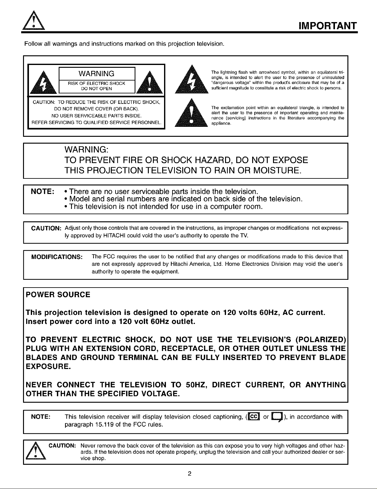
Follow atl warnings and instructions marked on this projection television.
IMPORTANT
WARNING
RISK OF ELECTRIC SHOCK
DO NOT OPEN
CAUTION: TO REDUCE THE RISK OF ELECTRIC SHOCK,
DO NOT REMOVE COVER (OR BACK).
NO USER SERVICEABLE PARTS INSIDE.
REFER SERVICING TO QUALIFIED SERVICE PERSONNEL.
WARNING:
TO PREVENT FIRE OR SHOCK HAZARD, DO NOT EXPOSE
I
NOTE: • There are no user serviceable parts inside the television.
I
CAUTION: Adjust only those controls that are covered in the instructions, as improper changes or modifications not express-
THIS PROJECTION TELEVISION TO RAIN OR MOISTURE.
• Model and serial numbers are indicated on back side of the television.
• This television is not intended for use in a computer room.
ly approved by HITACHI could void the user's authority to operate the TV.
angle, is intended to alert the user to the presence of uninsulated
"dangerous vottage" within the product's enclosure that may be of a
The lightning flash with arrowhead symbol, within an equilataral tri-
sufficient magnitude to constitute a risk of electric shock to persons.
The exclamation point within an equilataral triangle, is intended to
alert the user to the presence of important operating and mainte-
nance (servicing) instructions in the literature accompanying the
appliance.
I
I
I
MODIFICATIONS: The FCC requires the user to be notified that any changes or modifications made to this device that
are not expressly approved by Hitachi America, Ltd. Home Electronics Division may void the user's
authority to operate the equipment.
POWER SOURCE
This projection television is designed to operate on 120 volts 60Hz, AC current.
Insert power cord into a 120 volt 60Hz outlet.
TO PREVENT ELECTRIC SHOCK, DO NOT USE THE TELEVISION'S (POLARIZED)
PLUG WITH AN EXTENSION CORD, RECEPTACLE, OR OTHER OUTLET UNLESS THE
BLADES AND GROUND TERMINAL CAN BE FULLY INSERTED TO PREVENT BLADE
EXPOSURE.
NEVER CONNECT THE TELEVISION TO 50HZ, DIRECT CURRENT, OR ANYTHING
OTHER THAN THE SPECIFIED VOLTAGE.
This television receiver will display television closed captioning, ([1"_ or _), in accordance with I
I NOTE:
paragraph 15.119 of the FCC rules.
I
I
_ CAUTION: Never remove the back cover of the television as this can expose you to very high voltages and other haz-
viceards'shop,f the te ev s on does not operate properly, unp ug the te ev s on and ca your author zed dea er or ser-
2
SAFETY TIPS
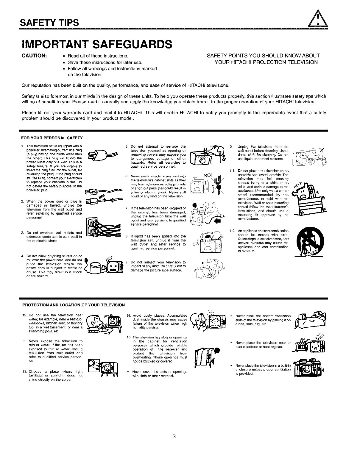
IMPORTANT SAFEGUARDS
CAUTION: • Read all of these instructions.
• Save these instructions for later use.
SAFETY POINTS YOU SHOULD KNOW ABOUT
YOUR HITACHI PROJECTION TELEVISION
• Follow all warnings and instructions marked
on the television.
Our reputation has been built on the quality, performance, and ease of service of HITACHI televisions.
Safety is also foremost in our minds in the design of these units. To help you operate these products properly, this section illustrates safety tips which
will be of benefit to you. Please read it carefully and apply the knowledge you obtain from it to the proper operation of your HITACHI television.
Please fill out your warranty card and mail it to HITACHI, This will enable HITACHI to notify you promptly in the improbable event that a safety
problem should be discovered in your product model.
FORYOURPERSONALSAFETY
1. This telewsion set is equipped with a
polarized aJfemating*current line plug J_t--"_ _
(a plug having one blade wider than
the other¸) This plug will fit into the
power ou'_af only one way_ This is a
safety feature¸ If you are unable to
insert the plug fully into the outlet, try
reversing the plug. If the plug should 6
still faJt to _, contact your efectdcian
to replace your obsolete outfet. Do
not defeat the safety purpose of the
peladzab plug¸ _
2_ When the power cord or plug is _
damaged or frayed_ unpEug the
_ievision _rom the wotl outlet and 7_
refer servicing to guaEtlied service
personnel
3. DO nol overload wail outlets and
extension cords as this can result in
fire or eleafric shock¸
4. DO not allow anything to rest on or ._,,
place the television where the 9
power cord is subject to traffic Or
rafl over the power cord, and do not _
abuse¸ This may result in a shock
or fire hazard¸
5 Do not attempt to service the
television yourself as opening or
removing covers may expose you
to dangerous voltage or other
hazards¸ Refer all servicing to
qualified service personnel¸
Never push objects of any kind into
the television's cabinet stets as they
may touch dangerous voltage poinfe
or short out parts that could tesutt in
a fire or electdc shock¸ Never spill
liquid of any kind on the television¸
If the television has been dropped or
the cabinet has beer* damaged,
unplug the television from the wall
outlet and refer serwcing to qualified
service pe_sonneJ
If iiquid has been apilied into the
teievisfen set, unplug it from the
wall outlet and refer service to
qualified service personnel.
DO not subject your television to
impact of any kind Be carafui not to
damage the picture tube surface.
10 UapIug the tefevision from the
wail outlet before cleaning Use a
damp cloth for cleaning. Do not
use liquid or aerosol cleaqers
11÷1. DO not ptace the television on an
unstable cart, stand, or table The
television may fail, causing
serious injury to a child or an
adult, and serious damage to the
appliance. Use only with a cart or
stand recommended by the
manufacturer, or sold with the
television. Wall Or shelf mounting
should follow the manufacturer's
instrtJafions, and should use a
mounting kit approved by the
manufaafure_
11+2. An appliance and car t combination
should be moved with care
Quick stops, excessive force, and
uneven surfaces m_y cause the
appliance and cart combinalion
to overturn¸
PROTECTION AND LOCATION OF YOUR TELEVISION
12 DO not use the television near
water, for example, near a balhtap,
washbowl, kitchen sink, or laundry
tub, in a wet basement, or near a
swimming pool, etc
• Never expose the television to
rain or wafer If the set has been
exposed to rain or wate_ unplug
television from walt outlet and
refer to qu_gied service person_
nel
13 Choose a place where light
(artgiciai or sunlight) does not
shine directly on the screen.
14 Avoid dusty places Accumulated _"t_ "-]_'_"i'3
dust inside the chassis may cause
failure of the television when high
humidity persists
15 The tefewsion has slots or openings
in the cabinet for ventilation
purposes which provide reliable
operation of the receiver and
protect the television from
overheating These openings must
not be blocked or covered¸
• Never cover the slofe or openings
with cloth or o_her matedaJ
".€,
3
• Never block the bottom ventilation
slofe of the television by placing it on
a bed, sofa, rug, efe
frl'_
• Never place the television near or _j_-_
over a radiator or heat register _
• Never place the television in a built-in
enclosure unless proper veafttafJon
is provided¸
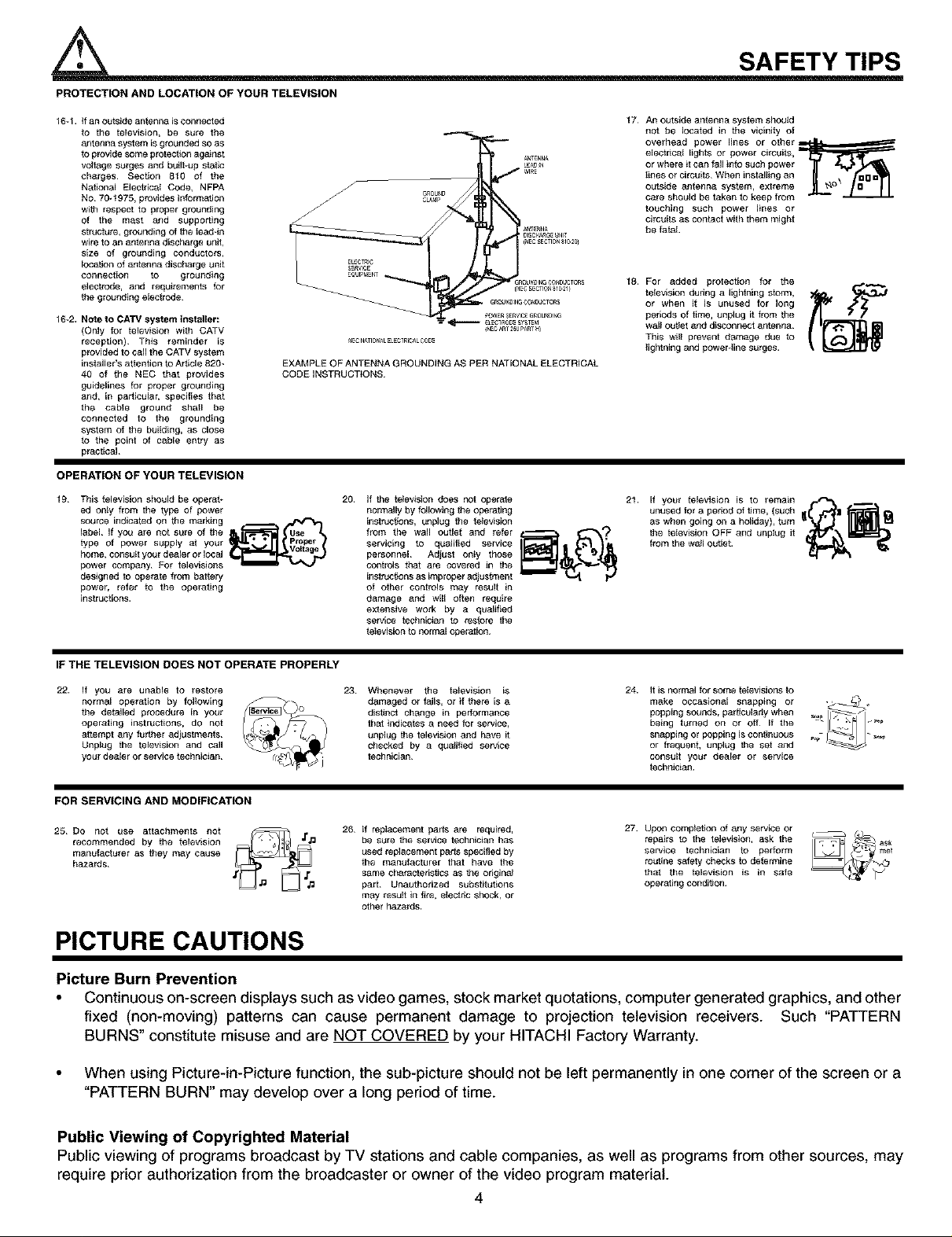
PROTECTION AND LOCATION OF YOUR TELEVISION
16-1. if an outside antenna isconnected
to the television, be sure the
antenna system is grounded so as
to provide some protection ag_nst
voltage surges and buithup static
charges¸ Section 810 of the
National Electhcat Code, NFPA
NO 70_t975, provides informa]Jon
with respect to proper grounding
of the mast and supporting
strdsture, grounding of the tead-in
wire to an antenna discharge unit,
size of grounding conductors,
location of 8ntsnna discharge unit
connection to grounding
electrode, and requirements for
the grounding elestrode
16-2. Note to CATV system installer:
(Only for televistsn with CATV
reception)¸ This reminder is
provided to call the CATV system
installer's attention to Article 820_
40 of the NEC that provides
guidelines for proper grounding
and, in particular, specifies that
the cabta ground shatl be
connected to the grounding
system of the building, as close
to the point of c_le entry as
practical
EXAMPLE OF ANTENNA GROUNDING AS PER NATIONAL ELECTRICAL
CODE iNSTRUCTIONS
OPERATION OF YOUR TELEVISION
19 This television should be operat÷
ed only from the type of power
source indicated on the marking
label if you are not sure of the
type of power suppEy at yeur
home_ consLItt your deaEer or Ioeal
power company_ Fer televisions
designed to eperate from battorg
power_ refer to the operating
instrucdons_
20.
if the telewsJon does Pot operate
normally by tollowing the operating
instructions, unplug the te_ewsion
from the wall outlet and refer _ _"--_)
servicing to qualified service lily.all _'_=_
personnel Adjust on_y those
controls that are covered in the
instruc_ons as improper adjustment
of other controls may result in
damage and will oftsn require
extensive work by a qua_gied
service tschnici_m to restore the
television to norma_ operation
SAFETY TIPS
17
An outside antenna system should
not be located in the vicinity of
overhead power lines or other L=,_=._===_"
eleofrtsat lights or power circuits,
or where it can fall into such power
tines or circuits¸ When inst allin gan
outside antenna system, extreme
care should be taken to keep from
touching such power lines or
circuits as contact with them might
be fatal
18
For added protection for the
television dudng a lightning storm,
or when it is un_Jsed for long
periods Of time, unplug it from the
wall out_et and disconnect antenna¸
This wilt prevent damage due to
lightning and powergine surges.
21. if your talevision is to remain
unused for a period of lime, (such
as when going on a holiday), thin _'_1 _
the television OFF _nd unplug it
from the w,, oL_t,et. _
IF THE TELEVISION DOES NOT OPERATE PROPERLY
22. if you are unable to restore
norma_ operation by foltowing
the detailed procedure in your
operating instructions, do not
a_tempt any further adjustments¸
Unplug the television and call
your dealer or service technician¸
23 Whenever the television is
damaged or fai_S, or if there is a
disSnof change in performance
thatindicatesa need for service,
unplug the telewsionand have it
checked by a doalg_ed service
technician¸
24. it iS normal for some televisions to
make occasional
being tomed on or off _f the
popping SOunds, par{ieL_tstlywhen _ /_11 _::
snapping or popping is continuous
or frequent, unplug the set 4_d
consult your dealer or service
tsehnician
snappmg or -_
FOR SERVICING AND MODIFICATION
27.
25 DO not use attachments not
recommended by the talev[sion
manufacturer as they may e_use
h_zards
26 if replacement parts are required,
be sure the service technician has
used replacement p_ts specified by
the manutacturer that have the
same characteristics as the origin_
part¸ Unauthorized substitutions
may result in fire, electsc shock, or
other hazards.
Upon compIstton of any service or
repairs to the telewsion, ask the
service technician to perform
rou]toe safety checks to determine
that the television is in safe
operating condglon
PICTURE CAUTIONS
Picture Burn Prevention
• Continuous on-screen displays such as video games, stock market quotations, computer generated graphics, and other
fixed (non-moving) patterns can cause permanent damage to projection television receivers. Such "PATTERN
BURNS" constitute misuse and are NOT COVERED by your HITACHI Factory Warranty.
• When using Picture-in-Picture function, the sub-picture should not be left permanently in one corner of the screen or a
"PATTERN BURN" may develop over a long period of time.
Public Viewing of Copyrighted Material
Public viewing of programs broadcast by TV stations and cable companies, as well as programs from other sources, may
require prior authorization from the broadcaster or owner of the video program material.
4
ACCESSORIES
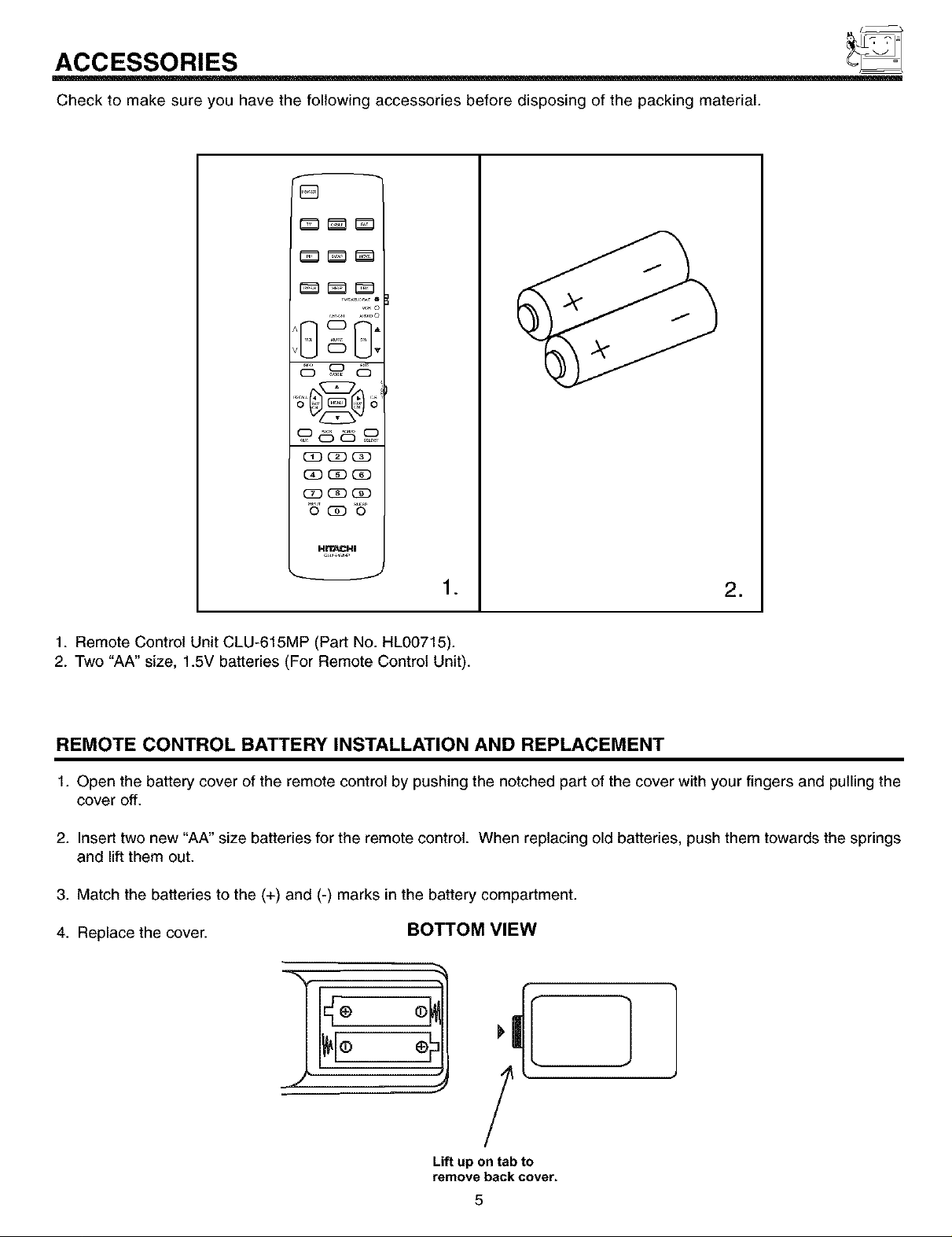
Check to make sure you have the following accessories before disposing of the packing material.
f
[]
(_ (3D(3D
•6' (i) o6r,
•
=
1. Remote Control Unit CLU-615MP (Part No. HL00715).
2. Two "AA" size, 1.5V batteries (For Remote Control Unit).
REMOTE CONTROL BATTERY INSTALLATION AND REPLACEMENT
1. Open the battery cover of the remote control by pushing the notched part of the cover with your fingers and pulling the
cover off.
2. Insert two new "AA" size batteries for the remote control. When replacing old batteries, push them towards the springs
and lift them out.
3. Match the batteries to the (+) and (-) marks in the battery compartment.
4. Replace the cover. BOTTOM VIEW
=
o
Lift up ontab to
remove back cover.
5
HOW TO SET UP YOUR NEW HITACHI PROJECTION TV
ANTENNA
Unless your TV is connected to a cable TV system or to a centralized antenna system, a good outdoor color TV antenna is
recommended for best performance. However, if you are located in an exceptionally good signal area that is free from interference and
multiple image ghosts, an indoor antenna may be sufficient.
LOCATION
Select an area where sunlight or bright indoor illumination will not fall directly on the picture screen. Also, be sure that the location
selected allows a free flow of air to and from the perforated back cover of the set.
To avoid cabinet warping, cabinet color changes, and increased chance of set failure, do not place the TV where temperatures can
become excessively hot, for example, in direct sunlight or near a heating appliance, etc.
VIEWING
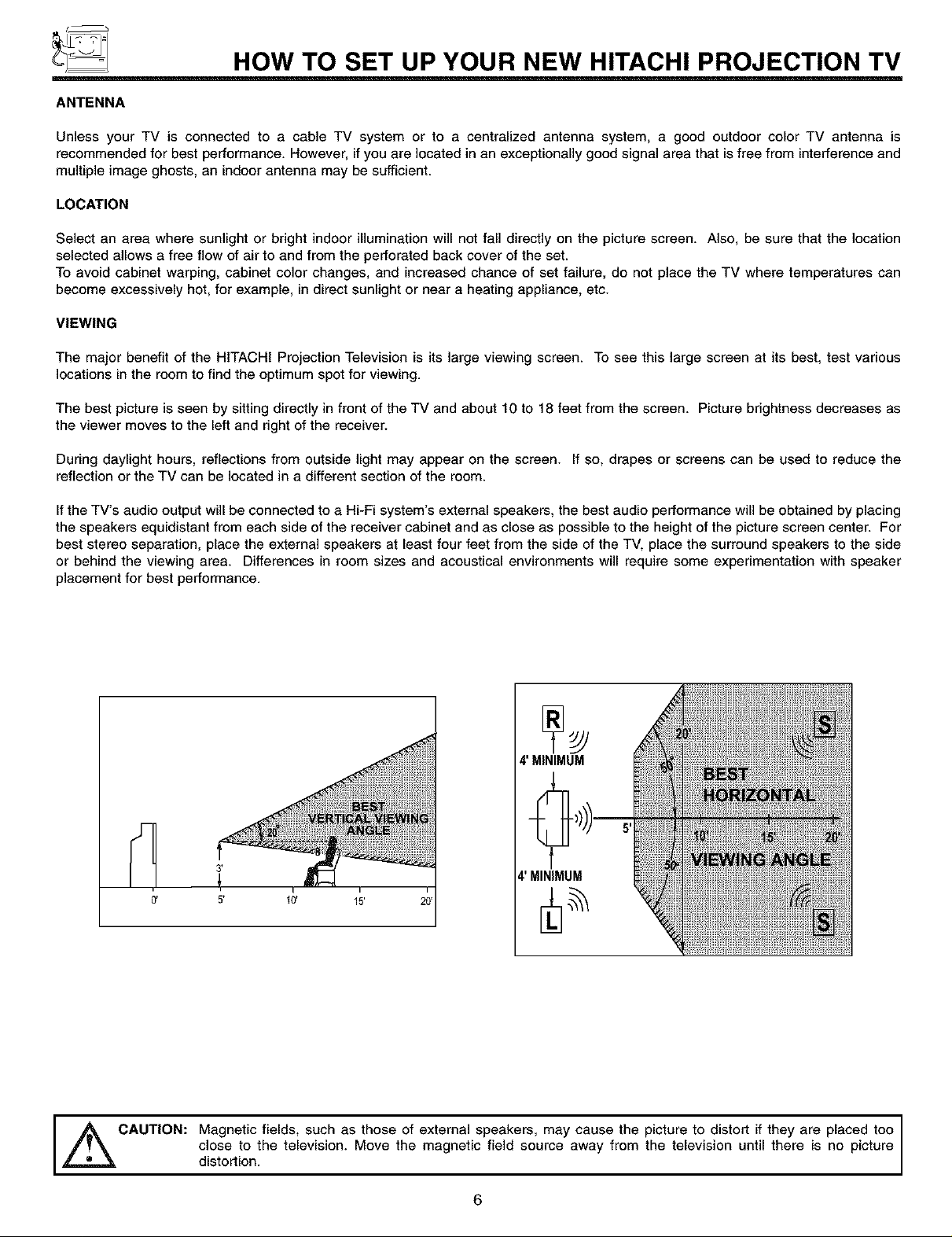
The major benefit of the HITACHI Projection Television is its large viewing screen. To see this large screen at its best, test various
locations in the room to find the optimum spot for viewing.
The best picture is seen by sitting directly in front of the TV and about 10 to 18 feet from the screen. Picture brightness decreases as
the viewer moves to the left and right of the receiver.
During daylight hours, reflections from outside light may appear on the screen. If so, drapes or screens can be used to reduce the
reflection or the TV can be located in a different section of the room.
Ifthe TV's audio output will be connected to a Hi-Fi system's external speakers, the best audio performance will be obtained by placing
the speakers equidistant from each side of the receiver cabinet and as close as possible to the height of the picture screen center. For
best stereo separation, place the external speakers at least four feet from the side of the TV, place the surround speakers to the side
or behind the viewing area. Differences in room sizes and acoustical environments will require some experimentation with speaker
placement for best performance.
4' MINIMUM
4' MINIMUM
0' 5' 40' 15'
i
CAUTION: Magnetic fields, such as those of external speakers, may cause the
,_ picture to distort if they are placed too I
distortion,closeto the television. Move the magnetic field source away from the television until there is no picture
6
I
HOOK-UP CABLES AND CONNECTORS
Most video/audio connections between components can be made with shielded video and audio cables that have phone connectors.
For best performance, video cables should use 75-Ohm coaxial shielded wire. Cables can be purchased from most stores that sell
audio/video products. Below are illustrations and names of common connectors. Before purchasing any cables, be sure of the output
and input connector types required by the various components and the length of each cable.
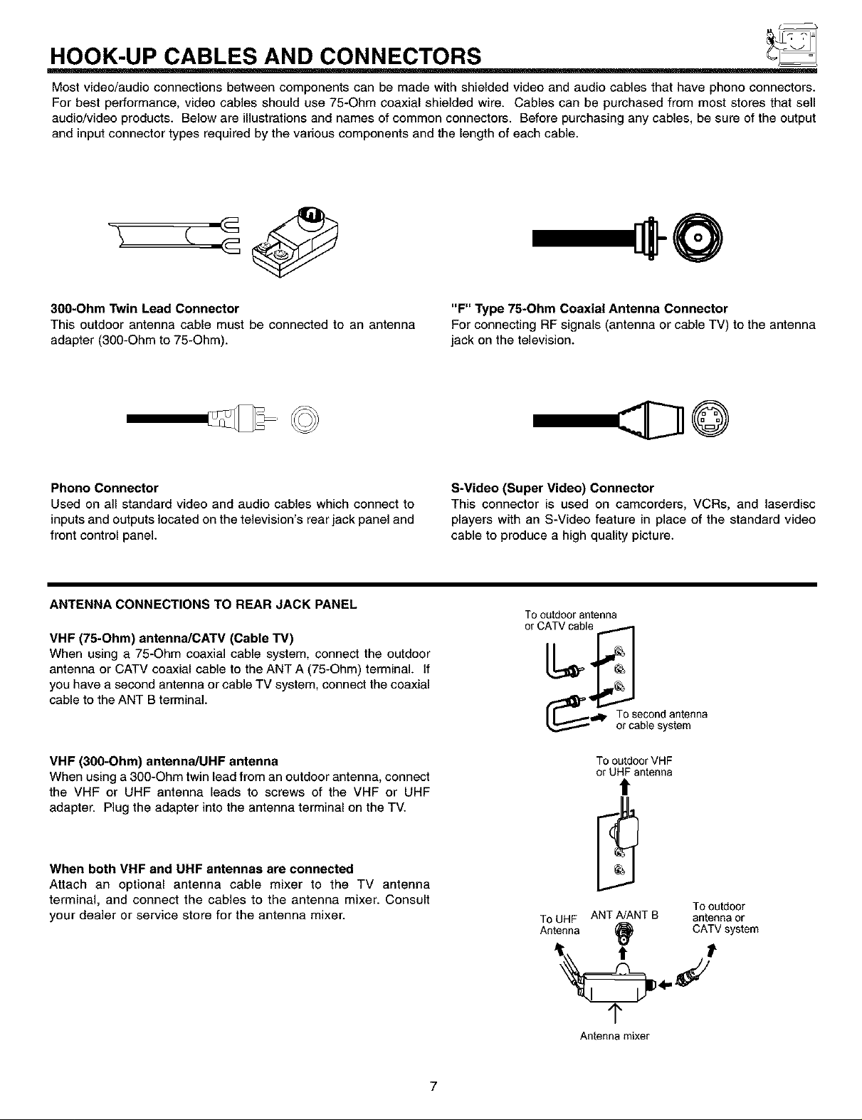
300-Ohm Twin Lead Connector
This outdoor antenna cable must be connected to an antenna
adapter (300-Ohm to 75-Ohm).
Phono Connector
Used on all standard video and audio cables which connect to
inputs and outputs located on the television's rear jack panel and
front control panel.
ANTENNA CONNECTIONS TO REAR JACK PANEL
VHF (75-Ohm) antenna/CATV (Cable TV)
When using a 75-Ohm coaxial cable system, connect the outdoor
antenna or CATV coaxial cable to the ANT A (75-Ohm) terminal. If
you have a second antenna or cable TV system, connect the coaxial
cable to the ANT B terminal.
"F" Type 75-Ohm Coaxial Antenna Connector
For connecting RF signals (antenna or cable TV) to the antenna
jack on the television.
S-Video (Super Video) Connector
This connector is used on camcorders, VCRs, and laserdisc
players with an S-Video feature in place of the standard video
cable to produce a high quality picture.
Tooutdoorantenna
o
_l_lp To second antenna
or cablesystem
VHF (300-Ohm) antenna/UHF antenna
When using a 300-Ohm twin lead from an outdoor antenna, connect
the VHF or UHF antenna leads to screws of the VHF or UHF
adapter. Plug the adapter into the antenna terminal on the TV.
When both VHF and UHF antennas are connected
Attach an optional antenna cable mixer to the TV antenna
terminal, and connect the cables to the antenna mixer. Consult
your dealer or service store for the antenna mixer.
To outdoorVHF
or UHF antenna
!
ToUHF ANT A/ANTB antennaor
Antenna (_ CATVsystem
Tooutdoor
1"
Antenna mixer
7
FRONT VIEW
CH+
FRONT PANEL CONTROLS
HITACHI
_-_ _) Pushopendoorand
pullforwardanddown.
CH+
( Q _ SOUNDR_R_EVALSYST_
POWER INPUT VOL-
® ® @
/
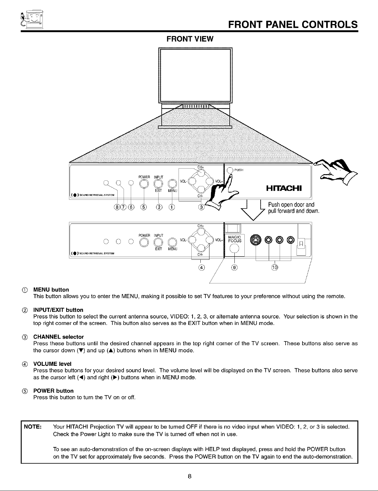
O MENU button
This button allows you to enter the MENU, making it possible to set TV features to your preference without using the remote.
Q INPUT/EXIT button
Press this button to select the current antenna source, VIDEO: 1,2, 3, or alternate antenna source. Your selection is shown in the
top right corner of the screen. This button also serves as the EXIT button when in MENU mode.
Q CHANNEL selector
Press these buttons until the desired channel appears in the top right corner of the TV screen. These buttons also serve as
the cursor down (_') and up (A) buttons when in MENU mode.
(_ VOLUME level
Press these buttons for your desired sound level. The volume level will be displayed on the TV screen. These buttons also serve
as the cursor left (,) and right (1_) buttons when in MENU mode.
(_ POWER button
Press this button to turn the TV on or off.
NOTE:
Your HITACHI Projection TV will appear to be turned OFF if there is no video input when VIDEO: 1,2, or 3 is selected.
Check the Power Light to make sure the TV is turned off when not in use.
To see an auto-demonstration of the on-screen displays with HELP text displayed, press and hold the POWER button
on the TV set for approximately five seconds. Press the POWER button on the TV again to end the auto-demonstration.
8
FRONT PANEL CONTROLS
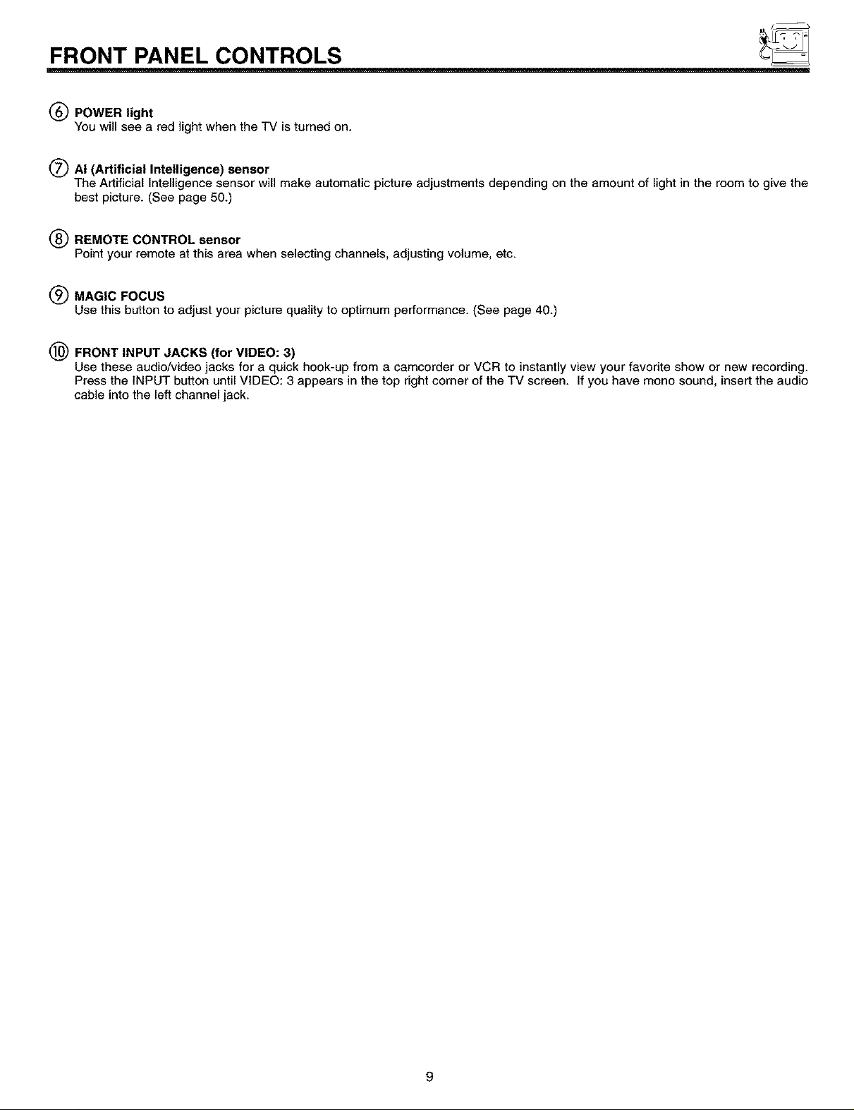
(_) POWER light
YOUwill see a red light when the TV is turned on.
(_ AI (Artificial Intelligence) sensor
The Artificial Intelligence sensor will make automatic picture adjustments depending on the amount of light in the room to give the
best picture. (See page 50.)
(_) REMOTE CONTROL sensor
Point your remote at this area when selecting channels, adjusting volume, etc.
(_ MAGIC FOCUS
Use thisbutton to adjust your picture quality tooptimumperformance.(See page 40.)
(_) FRONT INPUT JACKS (for VIDEO: 3)
Use these audio/video jacks for a quick hook-up from a camcorder or VCR to instantly view your favorite show or new recording.
Press the INPUT button until VIDEO: 3 appears in the top right corner of the TV screen. If you have mono sound, insert the audio
cable into the left channel jack.
9
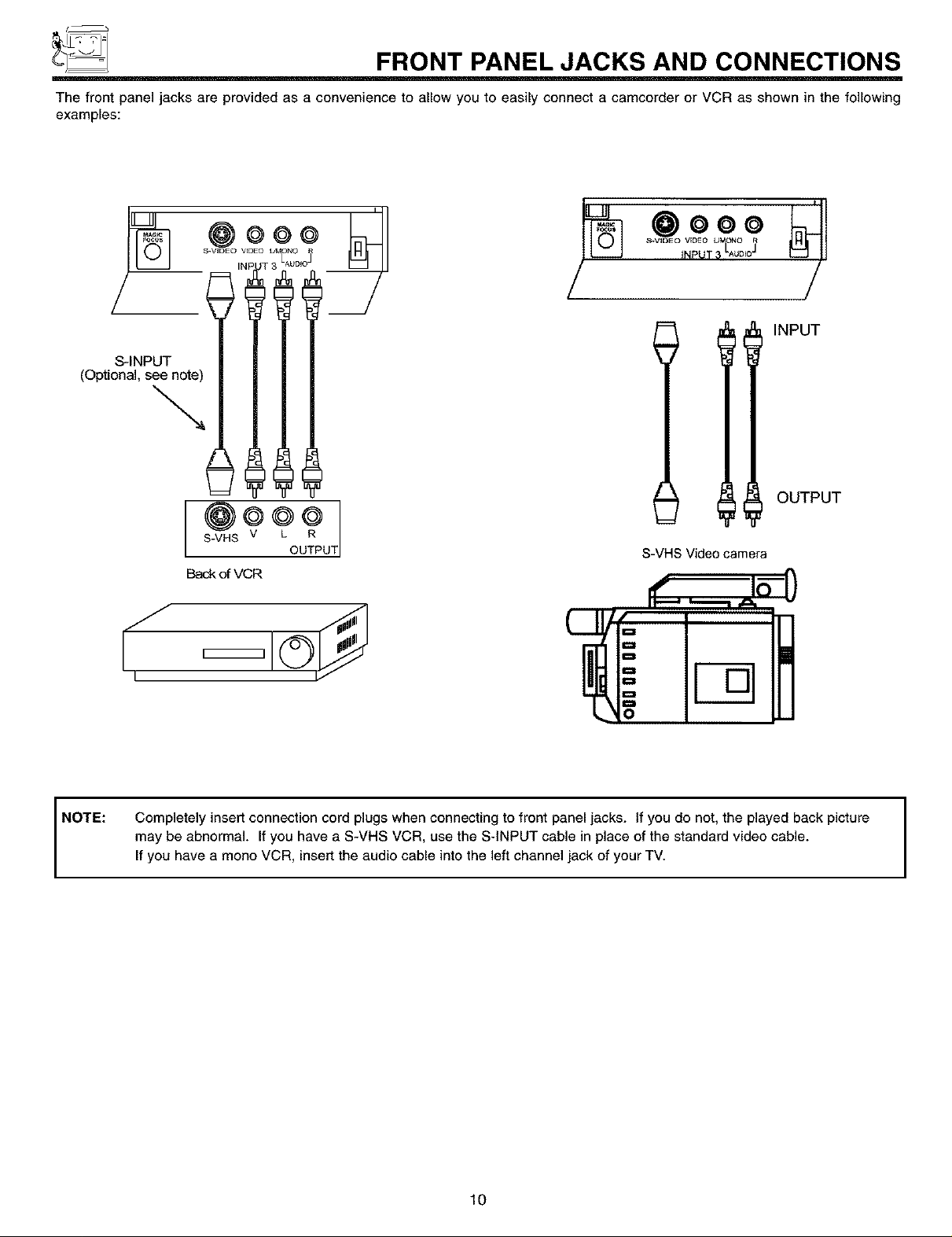
_ FRONT PANEL JACKS AND CONNECTIONS
The front panel jacks are provided as a convenience to allow you to easily connect a camcorder or VCR as shown in the following
examples:
S.VIDEO VEDEO UMONO
INPVT_LAUD=3
.ooo
IllNPuT
OUTPUT
NOTE:
S-VHS V
Back of VCR
Completely insert connection cord plugs when connecting to front panel jacks. If you do not, the played back picture
may be abnormal. If you have a S-VHS VCR, use the S-INPUT cable in place of the standard video cable.
If you have a mono VCR, insert the audio cable into the left channel jack of your TV.
UT
S-VHS Video camera
10
REAR PANEL JACKS
f
o
_ REAR SPRAWLER ][_ _ [_ ANTQ
CONVERTER
ANT£
_EXT
W_'LESS AU
CUr TO
®
®
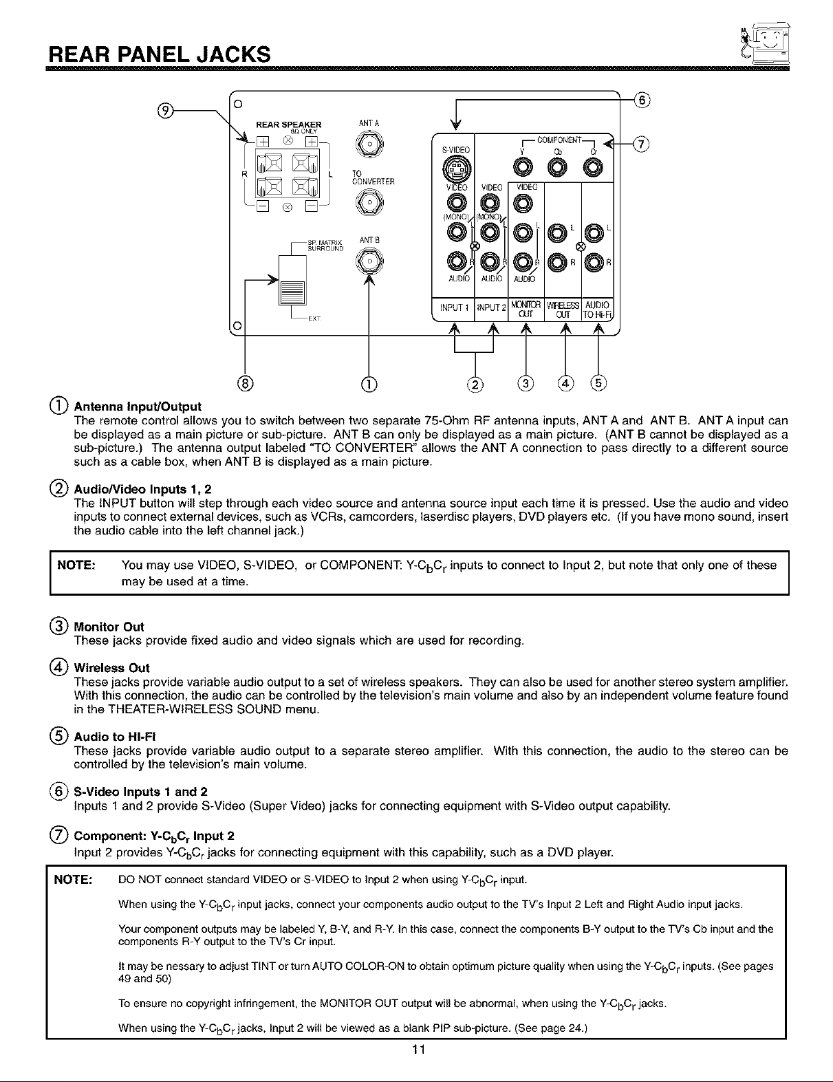
(_ Antenna Input/Output
The remote control allows you to switch between two separate 75-Ohm RF antenna inputs, ANT A and ANT B. ANT A input can
be displayed as a main picture or sub-picture. ANT B can only be displayed as a main picture. (ANT B cannot be displayed as a
sub-picture.) The antenna output labeled "TO CONVERTER" allows the ANT A connection to pass directly to a different source
such as a cable box, when ANT B is displayed as a main picture.
Audio/Video Inputs 1, 2
The INPUT button will step through each video source and antenna source input each time it is pressed. Use the audio and video
inputs to connect external devices, such as VCRs, camcorders, laserdisc players, DVD players etc. (If you have mono sound, insert
the audio cable into the left channel jack.)
NOTE:
You may use VIDEO, S-VIDEO, or COMPONENT: Y-CbC r inputs to connect to Input 2, but note that only one of these
may be used at a time.
(_) Monitor Out
These jacks provide fixed audio and video signals which are used for recording.
(_ Wireless Out
These jacks provide variable audio output to a set of wireless speakers. They can also be used for another stereo system amplifier.
With this connection, the audio can be controlled by the television's main volume and also by an independent volume feature found
in the THEATER-WIRELESS SOUND menu.
(_) Audio to HI-FI
These jacks provide variable audio output to a separate stereo amplifier. With this connection, the audio to the stereo can be
controlled by the television's main volume.
(_ S-Video Inputs 1 and 2
Inputs 1 and 2 provide S-Video (Super Video) jacks for connecting equipment with S-Video output capability.
(_ Component: ¥-CtoCr Input 2
Input 2 provides Y-CbC rjacks for connecting equipment with this capability, such as a DVD player.
NOTE: DO NOT connect standard VIDEO or S-VIDEO to Input 2 when using Y-CbC r input.
When using the Y-CbC r input jacks, connect your components audio output to the TV's Input 2 Left and Right Audio input jacks.
Your component outputs may be labeled Y, B-Y, and R-Y. In this case, connect the components B-Y output to the TV's Cb input and the
components R-Y output to the TV's Cr input.
It may be nessary to adjust TINT or turn AUTO COLOR-ON to obtain optimum picture quality when using the Y-CbC r inputs. (See pages
49 and 50)
To ensure no copyright infringement, the MONITOR OUT output will be abnormal, when using the Y-CbC r jacks.
When usingthe Y-CbCrjacks, Input 2will be viewed as a blank PIP sub-picture. (See page 24.)
11
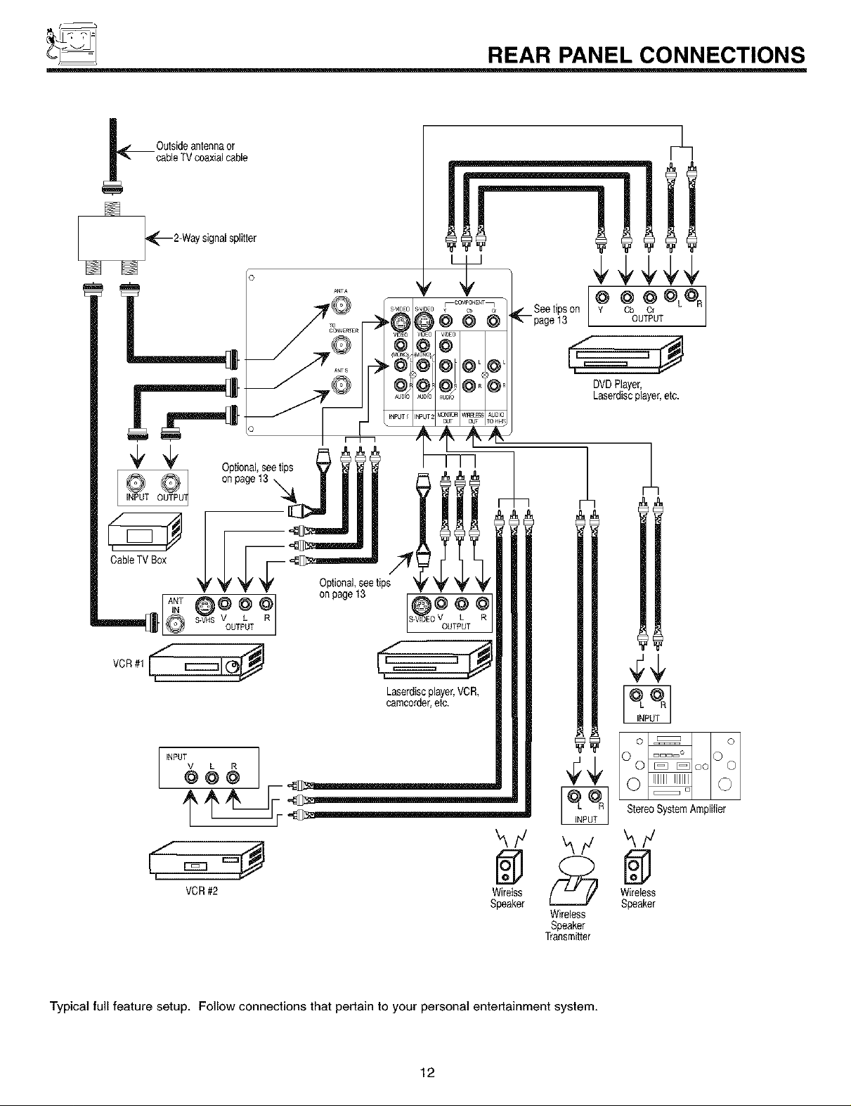
_ REAR PANEL CONNECTIONS
,_=== _
DVDPlayer,
Laserdiscplayer,etc.
k/
VCR#2 Wirelss
Speaker
Typical full feature setup. Follow connections that pertain to your personal entertainment system.
12
_,/ k/
Wireless
Speaker
Transmitter
Oo ooOo
WireleSss
Speaker
TIPS ON REAR PANEL CONNECTIONS
S-Video connections are provided for high performance laserdisc players, VCRs etc. that have this feature. Use these connections
in place of the standard video connection if your device has this feature.
If your device has only one audio output (mono sound), connect it to the left audio jack on the television.
Refer to the operating guide of your other electronic equipment for additional information on connecting your hook-up cables.
A single VCR can be used for VCR #1 and VCR #2, but note that a VCR cannot record its own video or line output (INPUT: 1 in the
example on page 12.) Refer to your VCR operating guide for more information on line input-output connections.
You may use VIDEO, S-VIDEO, or COMPONENT: Y-CbC r inputs to connect to Input 2, but note that only one of these may be used
at a time.
Connect only 1 component to each input jack.
COMPONENT: Y-CbC r connections are provided for high performance components, such as DVD players. Use these connections
in place of the standard video connection if your device has this feature.
When using the Y-CbC r input jacks, connect your components audio output to the TV's Input 2 Left and Right Audio input jacks.
Your component outputs may be labeled Y, B-Y, and R-Y. In this case, connect the components B-Y ouput to the TV's Cb input
and the components R-Y output to the TV's Cr input.
It may be necessary to adjust TINT or turn AUTO COLOR-ON to obtain optimum picture quality when using the Y-CbC r inputs. (See
pages 49 and 50.)
To ensure no copyright infringement, the MONITOR OUT output will be abnormal, when using the Y-CbC r jacks.
When using the Y-CbCr jacks, Input 2 will be viewed as a blank PIP sub-picture. (See page 24.)
13
_ EXTERNAL CONNECTIONS
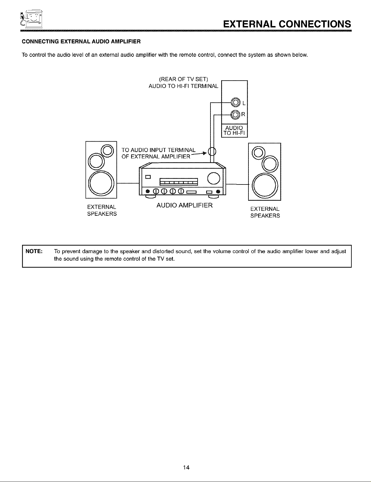
CONNECTING EXTERNAL AUDIO AMPLIFIER
To control the audio level of an external audio amplifier with the remote control, connect the system as shown below.
(REAR OF TV SET)
AUDIO TO HI-FI TERMINAL
-----@L
--OR
AUDIO
TO HI-FI
NOTE:
TO AUDIO INPUT TERMINAL _ (
OF EXTERNAL AMPLIFIER _ k
v J
I
%
©
EXTERNAL AUDIO AMPLIFIER
SPEAKERS SPEAKERS
To prevent damage to the speaker and distorted sound, set the volume control of the audio amplifier lower and adjust
the sound using the remote control of the TV set.
EXTERNAL
14
CONNECTING EXTERNAL VIDEO SOURCES
The exact arrangement you use to connect the VCR, camcorder, laserdisc player, and DVD player to your TV set is dependent on the
model and features of each component. Check the owner's manual of each component for the location of video and audio inputs and
outputs.
The following connection diagrams are offered as suggestions. However, you may need to modify them to accommodate your particular
assortment of components and features. For best performance, video and audio cables should be made from coaxial shielded wire.
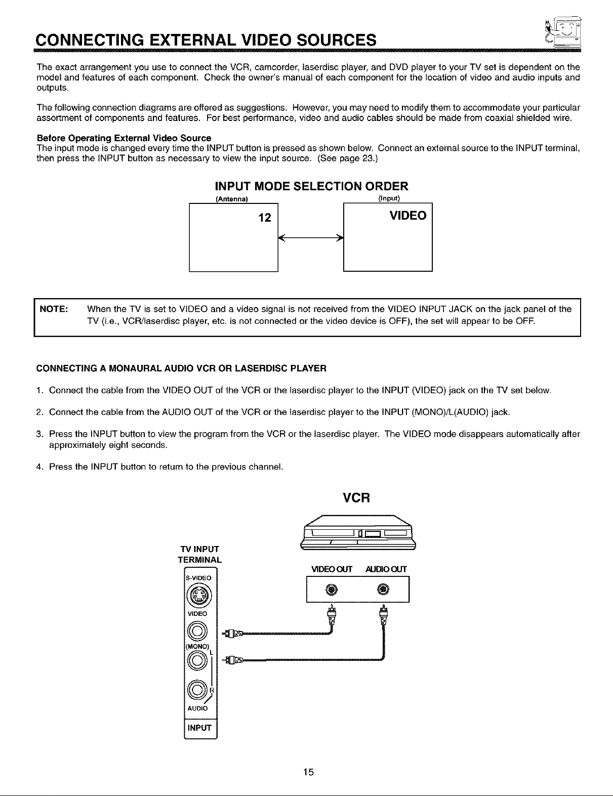
Before Operating External Video Source
The input mode is changed every time the INPUT button is pressed as shown below. Connect an external source to the INPUT terminal,
then press the INPUT button as necessary to view the input source. (See page 23.)
INPUT MODE SELECTION ORDER
(Antenna) (Input)
12 VIDEO
NOTE:
CONNECTING A MONAURAL AUDIO VCR OR LASERDISC PLAYER
1. Connect the cable from the VIDEO OUT of the VCR or the laserdisc player to the INPUT (VIDEO) jack on the TV set below.
2. Connect the cable from the AUDIO OUT of the VCR or the laserdisc player to the INPUT (MONO)/L(AUDIO) jack.
3. Press the INPUT button to view the program from the VCR or the laserdisc player. The VIDEO mode disappears automatically after
approximately eight seconds.
4. Press the INPUT button to return to the previous channel.
When the TV is set to VIDEO and a video signal is not received from the VIDEO INPUT JACK on the jack panel of the
TV (i.e., VCR/laserdisc player, etc. is not connected or the video device is OFF), the set will appear to be OFF.
VCR
g oc:= I
TV INPUT
TERMINAL
_-VIDEC
(@;
VIDEO
f_
(' , , )
VIDEOot.rr AUDIOOUT
® ®
IMONO)
f_
AUDIO
INPU1
15
CONNECTING EXTERNAL VIDEO SOURCES
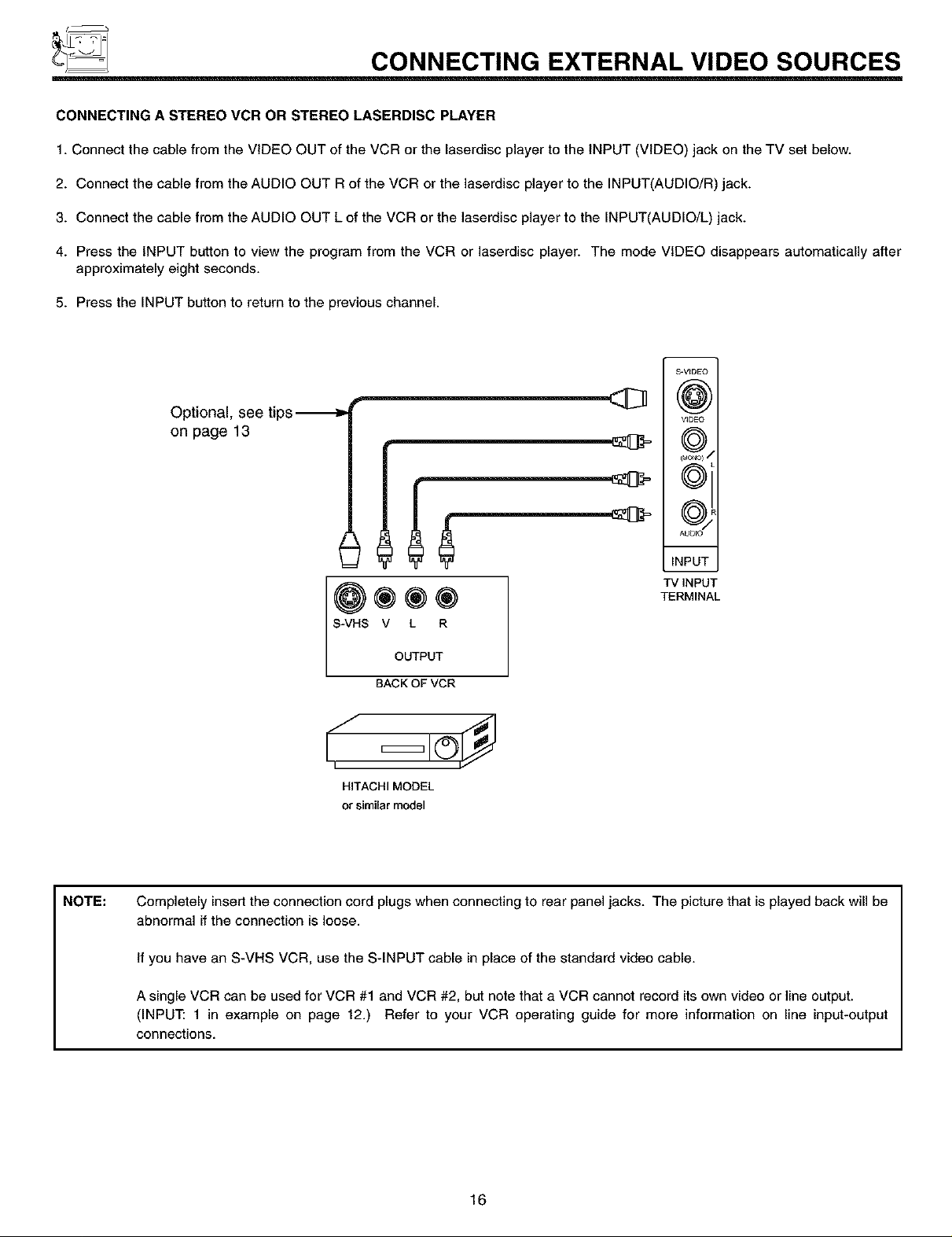
CONNECTING A STEREO VCR OR STEREO LASERDISC PLAYER
1. Connect the cable from the VIDEO OUT of the VCR or the laserdisc player to the INPUT (VIDEO) jack on the TV set below.
2. Connect the cable from the AUDIO OUT R of the VCR or the laserdisc player to the INPUT(AUDIO/R) jack.
3. Connect the cable from the AUDIO OUT L of the VCR or the laserdisc player to the INPUT(AUDIO/L) jack.
4. Press the INPUT button to view the program from the VCR or laserdisc player. The mode VIDEO disappears automatically after
approximately eight seconds.
5. Press the INPUT button to return to the previous channel.
S-VIDEO
(#3)
VIDEO
on page 13
_J
©i
NOTE:
Optional, see tips_
®®®
S-VHS V L R
OUTPUT
BACKOFVCR
HITACHIMODEL
or similarmodel
Completely insert the connection cord plugs when connecting to rear panel jacks. The picture that is played back will be
abnormal if the connection is loose.
If you have an S-VHS VCR, use the S-INPUT cable in place of the standard video cable.
©"
INPUT
TV INPUT
TERMINAL
A single VCR can be used for VCR #1 and VCR #2, but note that a VCR cannot record its own video or line output.
(INPUT: 1 in example on page 12.) Refer to your VCR operating guide for more information on line input-output
connections.
16
CONNECTING EXTERNAL VIDEO SOURCES
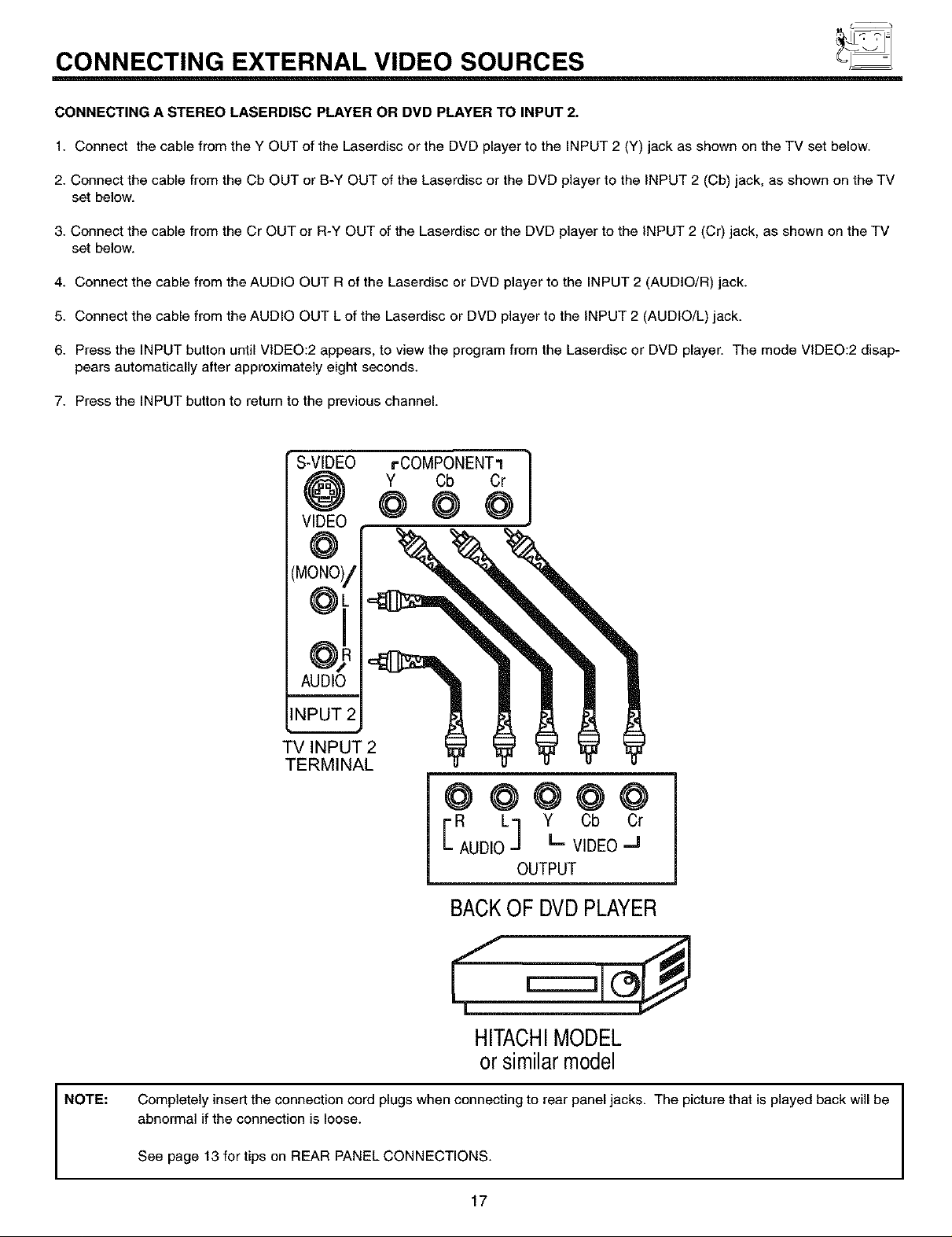
CONNECTING A STEREO LASERDISC PLAYER OR DVD PLAYER TO INPUT 2.
1. Connect the cable from the Y OUT of the Laserdisc or the DVD player to the INPUT 2 (Y) jack as shown on the TV set below.
2. Connect the cable from the Cb OUT or B-Y OUT of the Laserdisc or the DVD player to the INPUT 2 (Cb) jack, as shown on the TV
set below.
3. Connect the cable from the Cr OUT or R-Y OUT of the Laserdisc or the DVD player to the INPUT 2 (Cr) jack, as shown on the TV
set below.
4. Connect the cable from the AUDIO OUT R of the Laserdisc or DVD player to the INPUT 2 (AUDIO/R) jack.
5. Connect the cable from the AUDIO OUT L of the Laserdisc or DVD player to the INPUT 2 (AUDIO/L) jack.
6. Press the INPUT button until VIDEO:2 appears, to view the program from the Laserdisc or DVD player. The mode VIDEO:2 disap-
pears automatically after approximately eight seconds.
7. Press the INPUT button to return to the previous channel.
S-VIDEO
VIDEO
(MONO)/
°oi
INPUT 2
AUDIO
TV INPUT
TERMINAL
rCOMPONENT1
Y Cb Cr
@@@@@
ER obOr
AUD,O" V,DEO"
BACKOF DVDPLAYER
]
OUTPUT
NOTE:
HITACHIMODEL
orsimilarmodel
Completely insert the connection cord plugs when connecting to rear panel jacks. The picture that is played back will be
abnormal if the connection is loose.
See page 13 for tips on REAR PANEL CONNECTIONS.
17
f_
_ AUDIO SYSTEM SETUP
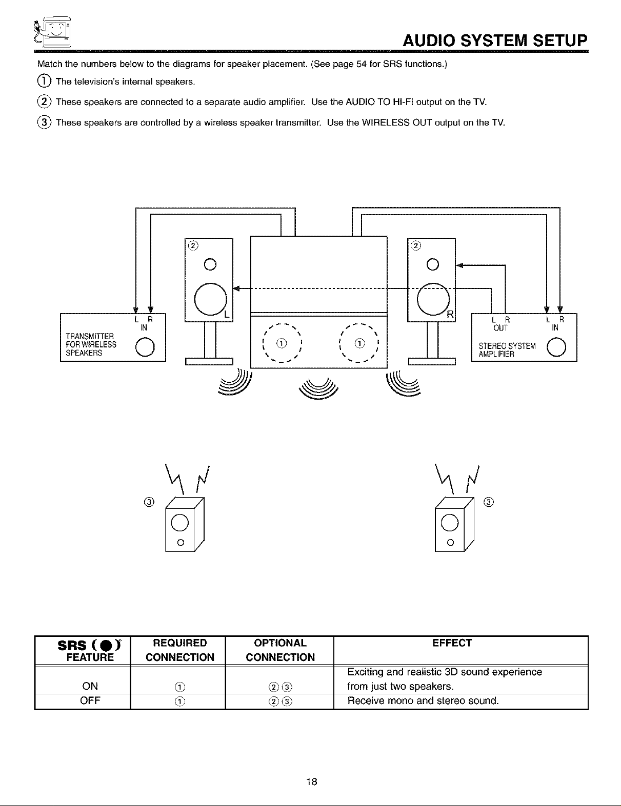
Match the numbers below to the diagrams for speaker placement. (See page 54 for SRS functions.)
(_The television's internal speakers.
(_) These speakers are connected to a separate audio amplifier. Use the AUDIO TO HI-FI output on the TV.
(_ These speakers are controlled by a wireless speaker transmitter. Use the WIRELESS OUT output on the TV.
I [
®
TRANSMITTER
FORWIRELESS 0
SPEAKERS
IN
LR1
®
0
©.
3
,_ % I j %
I \ \
, , _?]I@,
0
½
L R
OUT
STEREOSYSTEM
AMPLIFIER
ir
L R
IN
0
SRS ( • ) REQUIRED OPTIONAL EFFECT
FEATURE CONNECTION CONNECTION
Exciting and realistic 3D sound experience
ON L3_ _ _ from just two speakers.
OFF L3_ _ _ Receive mono and stereo sound.
18
THE GENIUS REMOTE CONTROL (CLU-615MP)
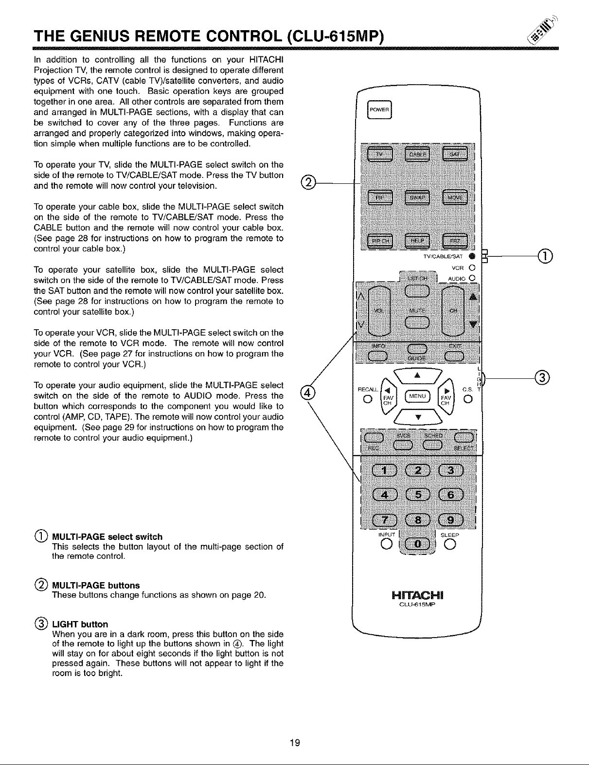
In addition to controlling all the functions on your HITACHI
Projection TV, the remote control is designed to operate different
types of VCRs, CATV (cable TV)/satellite converters, and audio
equipment with one touch. Basic operation keys are grouped
together in one area. All other controls are separated from them
and arranged in MULTI-PAGE sections, with a display that can
be switched to cover any of the three pages. Functions are
arranged and properly categorized into windows, making opera-
tion simple when multiple functions are to be controlled.
To operate your TV, slide the MULTI-PAGE select switch on the
side of the remote to TV/CABLE/SAT mode. Press the TV button
and the remote will now control your television.
To operate your cable box, slide the MULTI-PAGE select switch
on the side of the remote to TV/CABLE/SAT mode. Press the
CABLE button and the remote will now control your cable box.
(See page 28 for instructions on how to program the remote to
control your cable box.)
To operate your satellite box, slide the MULTI-PAGE select
switch on the side of the remote to TV/CABLE/SAT mode. Press
the SAT button and the remote will now control your satellite box.
(See page 28 for instructions on how to program the remote to
control your satellite box.)
TV/CABL_SAT _1
VCR O
AUDIO 0
0
To operate your VCR, slide the MULTI-PAGE select switch on the
side of the remote to VCR mode. The remote will now control
your VCR. (See page 27 for instructions on how to program the
remote to control your VCR.)
To operate your audio equipment, slide the MULTI-PAGE select
switch on the side of the remote to AUDIO mode. Press the
button which corresponds to the component you would like to
control (AMP, CD, TAPE). The remote will now control your audio
equipment. (See page 29 for instructions on how to program the
remote to control your audio equipment.)
(_ MULTI-PAGE select switch
This selects the button layout of the multi-page section of
the remote control.
MULTI-PAGE buttons
These buttons change functions as shown on page 20.
®
(_) LIGHT button
When you are in a dark room, press this button on the side
of the remote to light up the buttons shown in (_. The light
will stay on for about eight seconds if the light button is not
pressed again. These buttons will not appear to light if the
room is too bright.
19
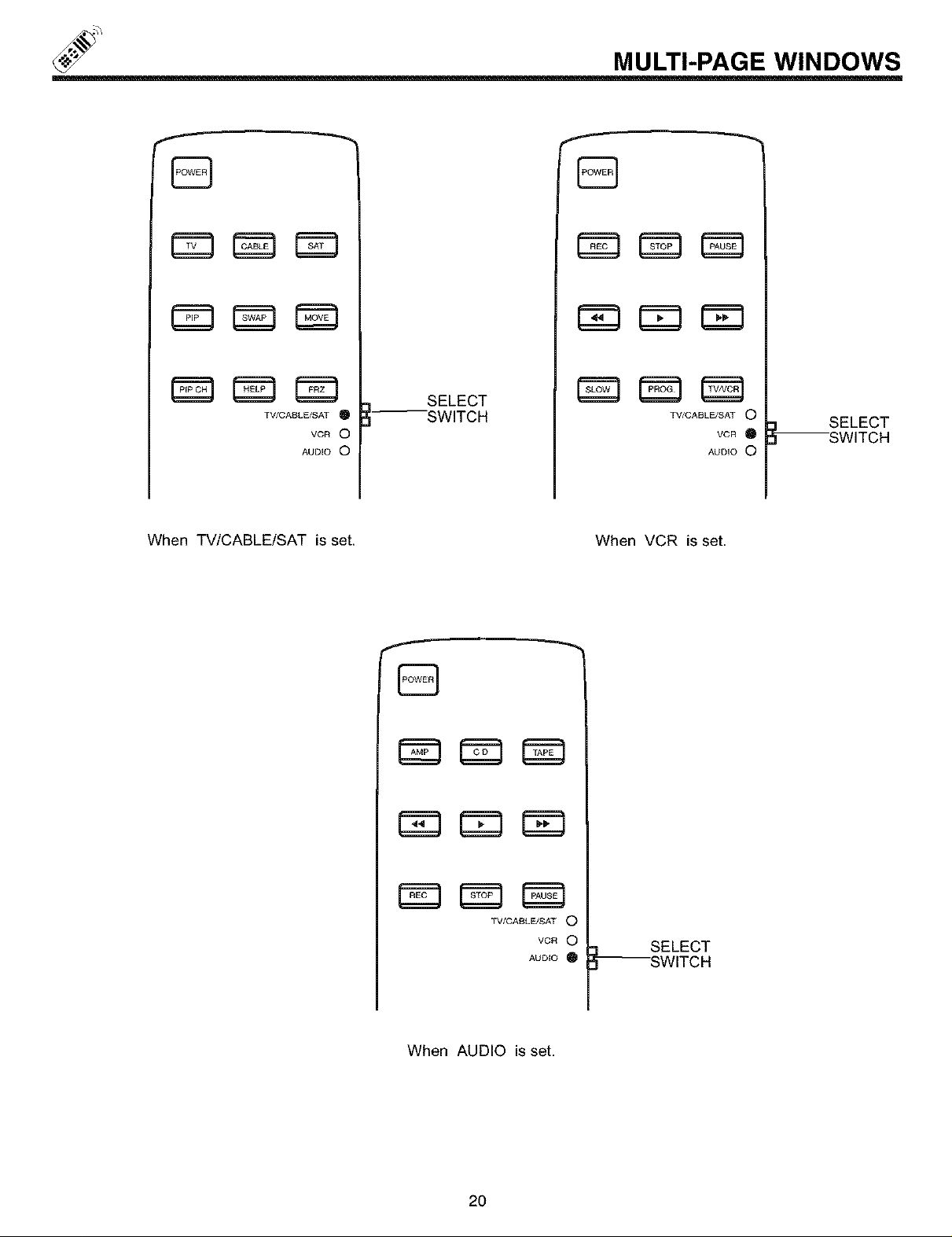
MULTI-PAGE WINDOWS
r_r=_ C_3
TV/CASLE/SAT I_
VCR 0
AUDIO O
When TV/CABLE/SAT is set. When VCR is set.
--SWITCH
SELECT
r_
TV/CABLE/SAT O
AUDIO O
B
r_m r=_ _3
VCR O
SELECT
--SWITCH
TV/CABLE/SAT O
VCR O
AUDIO
When AUDIO is set.
20
--SWITCH
SELECT
 Loading...