

Page 1

IMPORTANT
1
HITACHI
PROJECTION COLOR TV
60SX8B/9K 50SX6P 50UX18B/19K 46UX16B/17K
OPERATING GUIDE
TABLE OF CONTENTS
IMPORTANT......................................................................................................................3
SAFETY TIPS.....................................................................................................................4
PICTURE CAUTIONS.......................................................................................................9
ACCESSORIES................................................................................................................10
REMOTE CONTROL BATTERY INSTALLATION AND REPLACEMENT.......10
HOW TO SET UP YOUR NEW HITACHI PROJECTION TV......................................11
HOOK-UP CABLES AND CONNECTORS...................................................................13
ANTENNA CONNECTIONS TO REAR JACK PANEL.........................................14
FRONT PANEL CONTROLS..........................................................................................15
AVX (Audio/Video) selector..................................................................................15
VOLUME level ........................................................................................................15
CHANNEL selector ................................................................................................15
POWER button.......................................................................................................15
POWER light........................................................................................................... 15
AI (Artificial Intelligence) sensor...........................................................................15
REMOTE CONTROL sensor................................................................................15
V-SYNC (Vertical Hold) knob ...............................................................................15
FRONT INPUT JACKS (for VIDEO :3)...............................................................15
FRONT PANEL JACKS AND CONNECTIONS............................................................16
REAR PANEL JACKS.....................................................................................................17
Antenna Input / Output ..........................................................................................17
Audio/Video Inputs 1, 2.........................................................................................17
Output.......................................................................................................................17
Audio to Hi-Fi ..........................................................................................................17
Rear Speaker Terminals .......................................................................................17
S-Video ....................................................................................................................17
REAR PANEL CONNECTIONS.....................................................................................18
REAR SPEAKER TERMINAL CONNECTIONS ..........................................................19
TIPS ON REAR PANEL CONNECTIONS..............................................................20
AUDIO SYSTEM SET-UP...............................................................................................21
THE REMOTE CONTROL (CLU-850GR).....................................................................22
READY indicator light ............................................................................................22
SEND/LEARN indicator light ................................................................................22
LEARN/USE select switch....................................................................................22
MULTI-PAGE select switch ..................................................................................22
MULTI-PAGE buttons............................................................................................22
, LIGHT BUTTON................................................................................................22
MULTI-PAGE WINDOWS..............................................................................................23
HOW TO USE THE REMOTE TO CONTROL YOUR TV ...........................................24
POWER button.......................................................................................................24
RECALL button.......................................................................................................24
ANT button ..............................................................................................................24
MENU, ENTER, CURSOR buttons .....................................................................24
CHANNEL SELECTOR buttons...........................................................................25
AVX button ..............................................................................................................25
VOLUME, MUTE buttons......................................................................................25
LAST CHANNEL (LST-CH) b utton......................................................................26
PICTURE-IN-PICTURE buttons...........................................................................26
PICTURE-IN-PICTURE (PIP).........................................................................................27
PIP BUTTON..........................................................................................................27
EXCHNG (EXCHANGE) BUTTON.....................................................................27
SHIFT BUTTON.....................................................................................................27
FREEZE BUTTON................................................................................................27
1
Page 2

IMPORTANT
STROBE FREEZE................................................................................................28
USING THE REMOTE TO CONTROL VCR FUNCTIONS..........................................29
PRECODED VCR BUTTONS..............................................................................29
SELECT BUTTON..................................................................................................29
EXCLUSIVE TV BUTTONS..................................................................................29
USING THE REMOTE TO CONTROL CABLE BOX FUNCTIONS........................... 30
PRECODED FOR CABLE BOX...........................................................................30
SELECT BUTTON..................................................................................................30
EXCLUSIVE TV BUTTONS..................................................................................30
VCR AND CABLE BOX CODES ...................................................................................31
TABLE 1. VCR Precoded remote controls.............................................................31
TABLE 2. Cable Box Precoded remote controls...................................................32
USING THE GENIUS REMOTE TO LEARN ADDITIONAL FUNCTIONS...............33
LEARNABLE BUTTONS.......................................................................................33
EXCLUSIVE BUTTONS........................................................................................33
EASY GRAPHIC GUIDE ................................................................................................36
SET UP..............................................................................................................................38
FAVORITE CHANNELS.................................................................................................41
RESET...............................................................................................................................42
PROGRAM.......................................................................................................................43
CLOCK .............................................................................................................................45
VIDEO ..............................................................................................................................47
AUDIO..............................................................................................................................50
CARE OF YOUR HITACHI PROJECTION TV AND YOUR REMOTE CONTROL..54
RECEPTION PROBLEMS...............................................................................................55
CHECK HERE BEFORE CALLING FOR SERVICE.....................................................56
SPECIFICATIONS...........................................................................................................57
NOTES..............................................................................................................................59
WARRANTY CARD, front..............................................................................................61
HITACHI PROJECTION TV LIMITED WARRANTY.............................................61
WARRANTY CARD, back..............................................................................................63
30 - 48
2
Page 3
IMPORTANT
IMPORTANT
Follow all warnings and instructions marked on this television receiver.
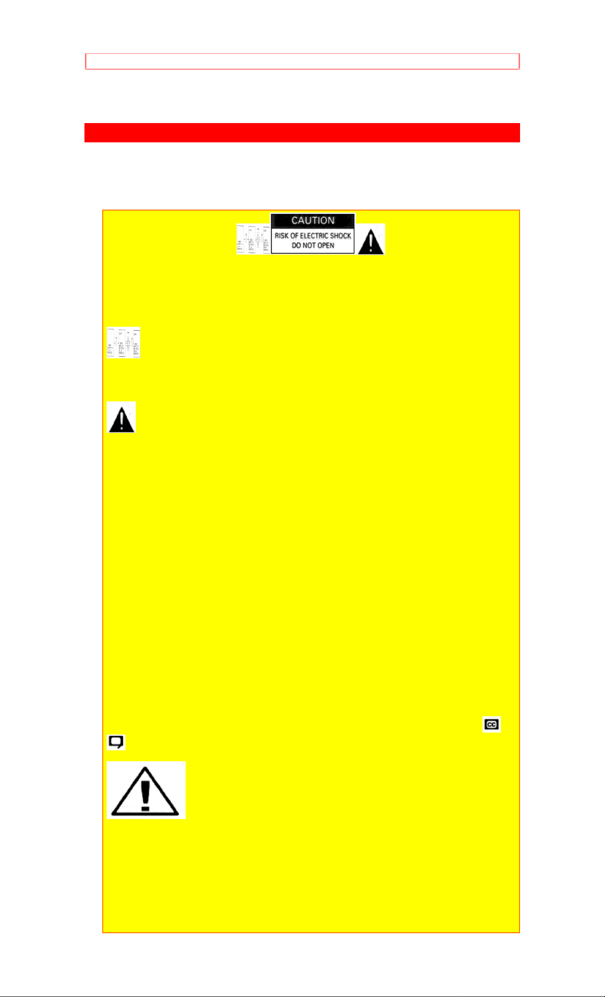
CAUTION: TO REDUCE THE RISK OF ELECTRIC SHOCK,
DO NOT REMOVE COVER (OR BACK).
NO USER-SERVICEABLE PARTS INSIDE.
REFER SERVICING TO QUALIFIED SERVICE PERSONNEL.
The lightning flash with arrowhead symbol, within an equilateral
triangle, is intended to alert the user to the presence of uninsulated
"dangerous voltage" within the product's enclosure that may be of sufficient
magnitude to constitute a risk of electric shock to persons.
The exclamation point within an equilateral triangle is intended to alert
the user to the presence of important operating and maintenance (servicing)
instructions in the literature accompanying the appliance.
WARNING:
TO PREVENT FIRE OR SHOCK HAZARD, DO NOT EXPOSE THIS
TELEVISION SYSTEM TO RAIN OR MOISTURE.
NOTE: • There are no user serviceable parts inside the receiver.
• Model number and serial number are indicated on the back
side of the set.
POWER SOURCE:
This projection color TV is designed to operate on 120 volts 60 Hz, AC
household current.
Insert power cord into a 120 volt 60 Hz outlet.
TO PREVENT ELECTRIC SHOCK, DO NOT USE THE TELEVISION'S
PLUG WITH AN EXTENSION CORD, RECEPTACLE, OR OTHER OUTLET
UNLESS THE BLADES AND GROUND TERMINAL CAN BE FULLY
INSERTED TO PREVENT BLADE EXPOSURE.
NEVER CONNECT THE TV TO 50 Hz, DIRECT CURRENT, OR ANYTHING
OTHER THAN THE SPECIFIED VOLTAGE.
NOTE: This television receiver will display television closed cap t ioning ( or
), in accordance with paragraph 15, 119 of the FCC rules.
CAUTION: Never remove the back cover of the set as this
can expose you to very high voltages and other hazards. If the set does not
operate properly, unplug the set and call your dealer or service shop.
HITACHI's 60SX8B, 60SX9K and 50SX6P employ state-of-the-art computer
circuits to enhance picture performance. Should your projection TV become
unplugged from the AC wall outlet or lose AC power due to a local power
failure, please wait at least 30 seconds following the return of power before
turning on your TV. This will allow the compu t ers time to check/ correct any
internal errors caused by the loss of power.
3
Page 4
SAFETY TIPS
SAFETY TIPS
IMPORTANT SAFEGUARDS
SAFETY POINTS YOU SHOULD KNOW ABOUT
YOUR HITACHI TELEVISION RECEIV ER
CAUTION:
* Read all of these instructions.
* Save these instructions for later use.
* Follow all warnings and instructions marked on the television receiver.
Our reputation has been built on the quality, performance, and ease of
service of HITACHI television receivers.
Safety is also foremost in our minds in the design of these units. To help you
operate these products properly, this section illustrates safety tips which will
be of benefit to you. Please read it carefully and apply the knowledge you
Obtain from it to the proper operation of your HITACHI television receiver.
Please fill out your warranty card at once and mail it to HITACHI. This will
enable HITACHI to notify you promptly in the improbable event that a safety
problem should be discovered in your model of product.
FOR YOUR PERSONAL SAFETY
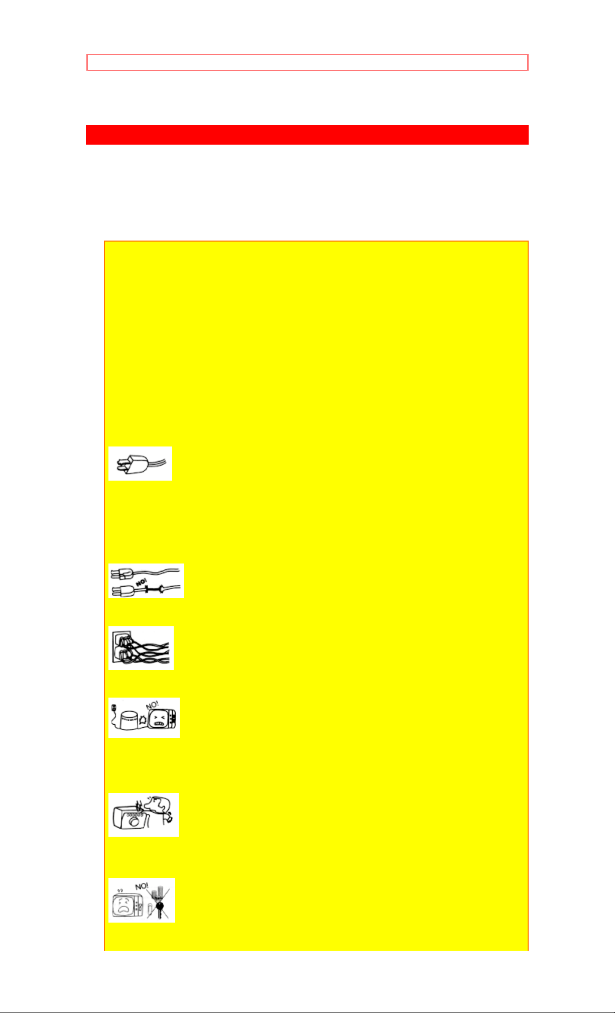
1 This television set is equipped with a polarized alternating-current line plug
(a plug having one blade wider than the other). This plug will fit into the power
outlet only one way. This is a safety feature. If you are unable to insert the
plug fully into the outlet, try reversing the plug. If the plug should still fail to fit,
contact your electrician to replace your obsolete outlet. Do not defeat the
safety purpose of the polarized plug.
2 When the power cord or plug is damaged or frayed, unplug this television
set from the wall outlet and refer servicing to qualified service personnel.
3 Do not overload wall outlets and extension cords as this can result in fire or
electric shock.
4 Do not allow anything to rest on or roll over the power cord, and do not
place the TV where the
power cord is subject to traffic or abuse. This may result in a shock or fire
hazard.
5 Do not attempt to service this television set yourself as opening or removing
covers may expose you to dangerous voltage or other hazards. Refer all
servicing to qualified service personnel.
6 Never push objects of any kind into this television set through cabinet slots
as they may touch dangerous voltage points or short out parts that could
4
Page 5
SAFETY TIPS
result in a fire or electric shock. Never spill liquid of any kind on the television
set.
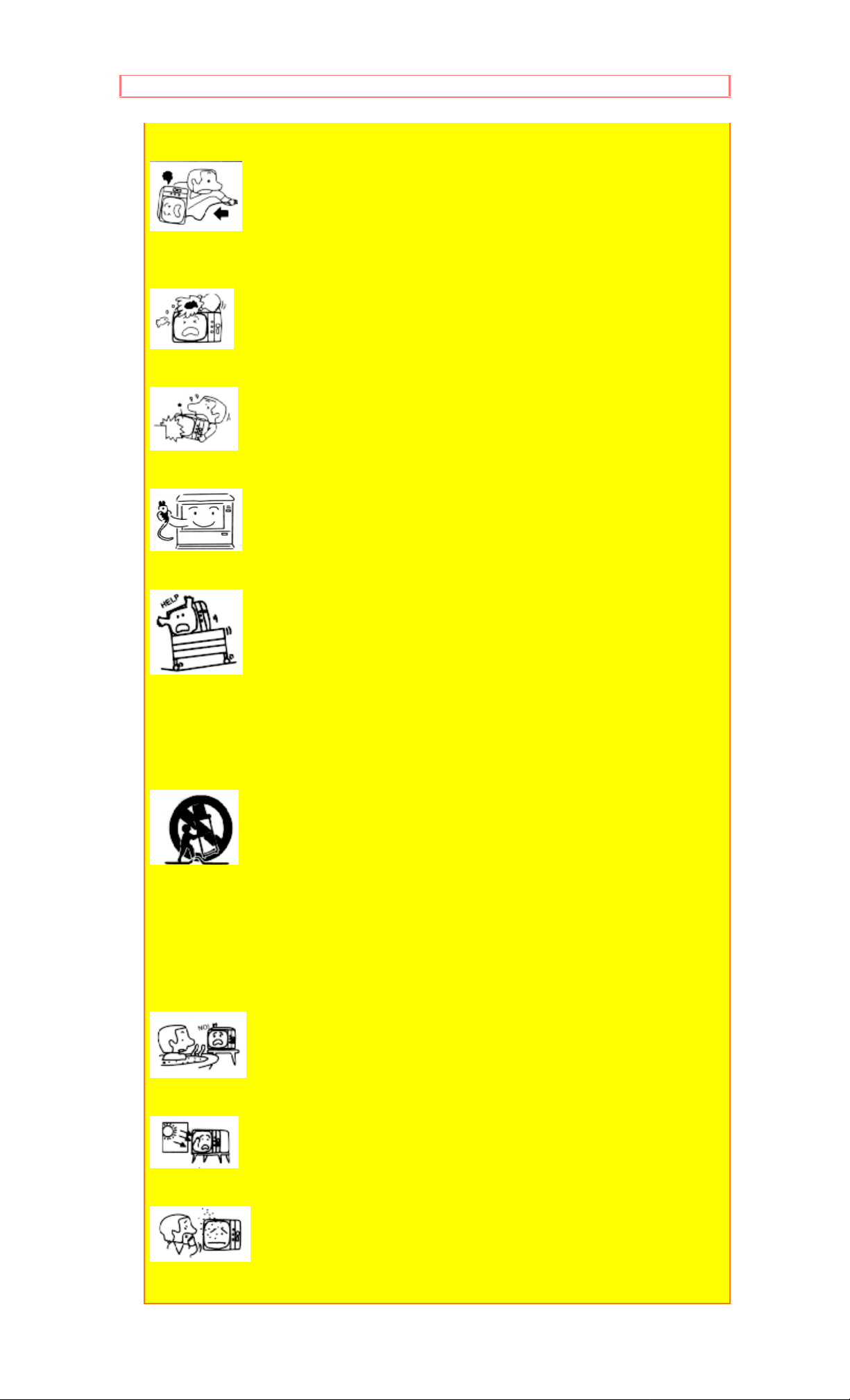
7 If the television set has been dropped or the cabinet has been damaged,
unplug this television set from the wall outlet and refer servicing to qualified
service personnel.
8 If liquid has been spilled into this television set, unplug it from the wall outlet
and refer service to qualified service personnel.
9 Do not subject your television set to impact of any kind. Be particularly
careful not to damage the picture tube surface.
10 Unplug this television set from the wall outlet before cleaning. Do not use
liquid cleaners or aerosol cleaners. Use a damp cloth for cleaning.
11-1 Do not place this television set on an unstable cart, stand, or table. The
television set may fall, causing serious injury to a child or an adult, and
serious damage to the appliance. Use only with a cart or stand recommended
by the manufacturer, or sold with the television set. Wall or shelf mounting
should follow the manufacturer's instructions, and should use a mounting kit
approved by the manufacturer.
11-2 An appliance and cart combination should be moved with care. Quick
stops, excessive force, and uneven surfaces may cause the appliance and
cart combination to overturn.
PROTECTION AND LOCATION OF YOUR SET
12 Do not use this television set near water, for example, near a bathtub,
washbowl, kitchen sink, or laundry tub, in a wet basement, or near a
swimming pool, etc.
• Never expose the set to rain or water. If the set has been exposed to rain or
water, unplug the set from the wall outlet and refer servicing personnel.
13 Choose a place where light (artificial or sunlight) does not shine directly on
the screen.
14 Avoid dusty places, since accumulated dust inside the chassis may cause
failure of the set when high humidity persists.
5
Page 6
SAFETY TIPS
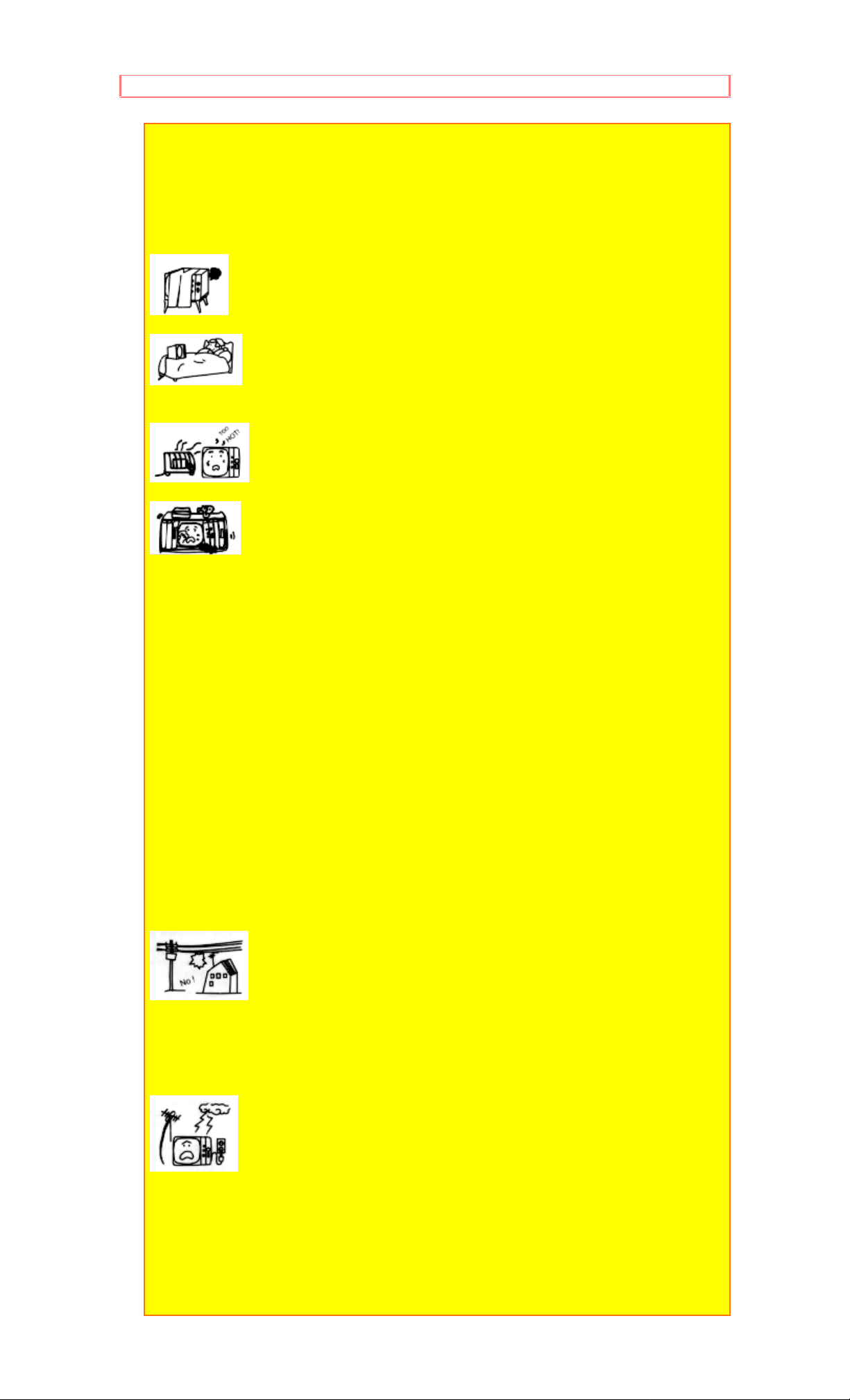
15 The set has slots, or openings in the cabinet for ventilation purposes, to
provide reliable operation of the receiver, and to protect from overheating.
These openings must not be blocked or covered.
• Never cover the slots or openings with cloth or other material.
• Never block the bottom ventilation slots of the set by placing it on a bed,
sofa, rug, etc.
• Never place the set near or over a radiator or heat register.
• Never place the set in a "built-in" enclosure, unless proper ventilation
provided.
PROTECTION AND LOCATION OF YOUR SET
16-1 If an outside antenna is connected to the television set, be sure the
antenna system is protected against voltage surges and built up static
charges, Section 810 of the National Electrical Code, NFPA No. 70-1975,
provides information with respect to proper grounding of the mast and
supporting structure, grounding of the lead-in wire to an antenna discharge
unit, size of grounding conductors, location of antenna discharge unit,
connection to grounding electrode, and requirements for the grounding
electrode.
Click to see antenna grounding diagram.
16-2 Note to CATV system installer: (Only for the television set with CATV
reception) This reminder is provided to call the CATV system installer's
attention to Article 820-40 of the NEC that provides guidelines for proper
grounding and, in particular, specifies that the cable ground shall be
connected to the grounding system of the building, as close to the point of
cable entry as practical.
17 An outside antenna system should not be located in the vicinity of
overhead power lines or other electrical lights or power circuits, or where it
can fall into such power lines or circuits. When installing an outside antenna
system, extreme care should be taken to keep from touching such power
lines or circuits as contact with them might be fatal.
18 For added protection for this television set during a lightning storm, or
when it is left unattended and unused for long periods of time, unplug it from
the wall outlet and disconnect the antenna. This will prevent damage due to
lightning and power-line surges.
6
Page 7
SAFETY TIPS
OPERATION OF YOUR SET
19 This television set should be operated only from the type of power source
indicated on the marking label. If you are not sure of the type of power supply
at your home, consult your television dealer or local power company. For
television sets designed to operate from battery power, refer to the operating
instructions.
20 If the television set does not operate normally by following the operating
instructions, unplug this set television set from the wall outlet and refer
servicing to qualified service personnel. Adjust only those controls that are
covered in the operating instructions as improper adjustment of other controls
may result in damage and will often require extensive work by a qualified
technician to restore the television set to normal operation.
21 When going on a holiday: If your television set is to remain unused for a
period of time, turn the television set "off" and unplug it from the wall outlet.
IF THIS SET DOES NOT OPERATE PROPERLY
22 If you are unable to restore normal operation by following the detailed
procedure in your operating instructions, do not attempt any further
adjustment. Unplug the set and call your dealer or service technician.
23 Whenever the television set is damaged or fails, or a distinct change in
performance indicates a need for service, unplug the set and have it checked
by a professional service technician.
24 It is normal for some TV sets to make occasional snapping or popping
sounds, particularly when being turned on or off. If the snapping or popping is
continuous or frequent, unplug the set and consult your dealer or service
technician.
FOR SERVICING AND MODIFICATION
25 Do not use attachments not recommended by the television set
manufacturer as they may cause hazards.
26 When replacement parts are required, be sure the service technician has
used replacement parts specified by the manufacturer that have the same
characteristics as the original part. Unauthorized substitutions may result in
fire, electric shock, or other hazards.
7
Page 8

SAFETY TIPS
27 Upon completion of any service or repairs to the television set, ask the
service technician to perform routine safety checks to determine that the
television is in safe operating condition.
8
Page 9

PICTURE CAUTIONS
PICTURE CAUTIONS
WARNING
Continuous on-screen displays such as video games, stock market
quotations, computer generated graphics, and other fixed (non-moving)
patterns can cause permanent damage to projection television receivers.
Such "PATTERN BURNS" constitute misuse and are NOT COVERED by
your Hitachi Factory Warranty.
When using the Picture-in-Picture function, the sub-picture should not be
left permanently in one corner of the screen or a "pattern burn" may
develop over a long period of time.
This projection television receiver was intended mainly for the private
viewing of programs broadcast by TV stations and cable companies and
programs from other video sources. Public viewing may require prior
authorization from the broadcaster or owner of the video program.
9
Page 10
ACCESSORIES
ACCESSORIES
Check to make sure you have the following accessories before disposing
of the packing material.
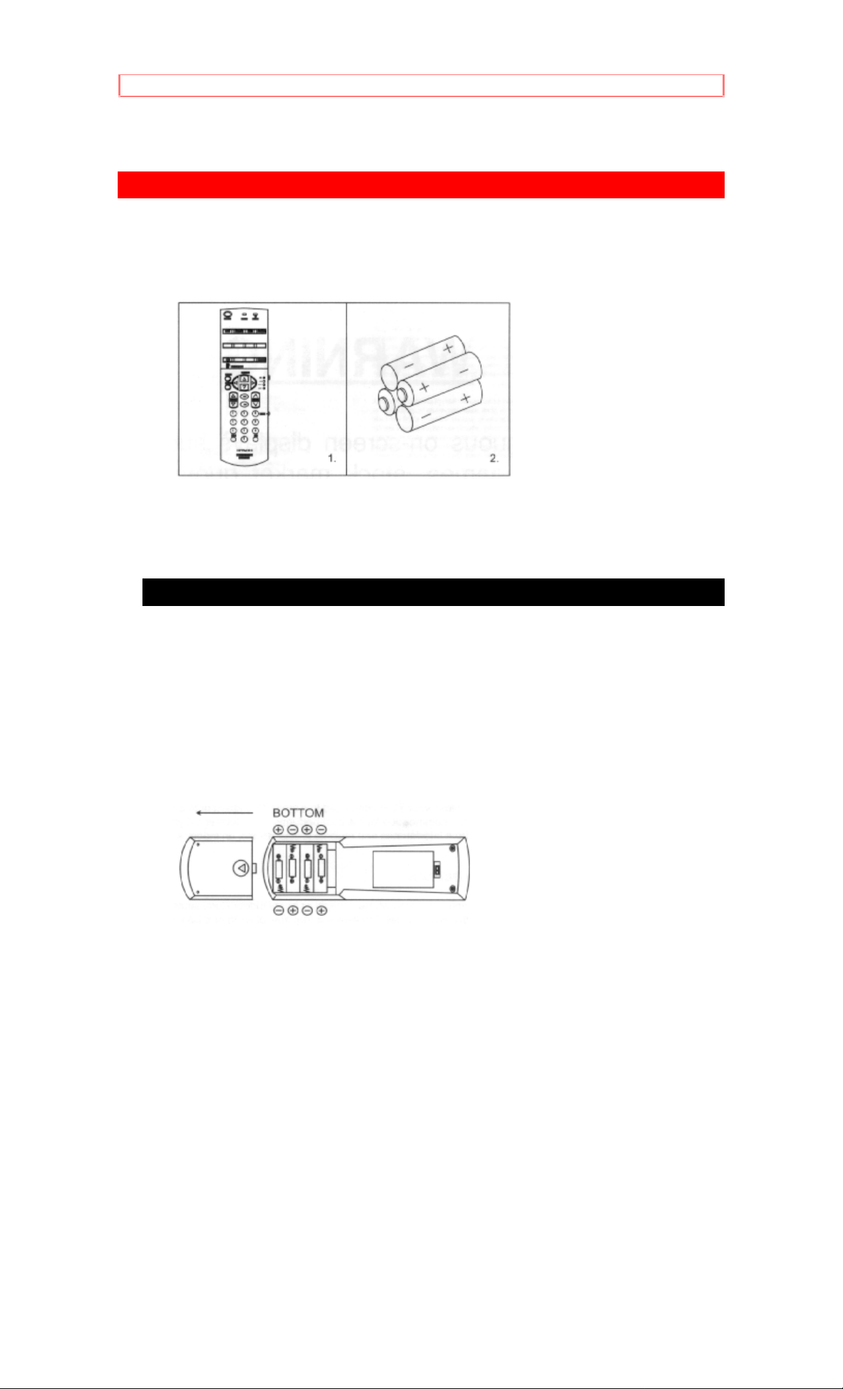
1. Genius Remote Control Unit CLU-850GR (part No.2573971)
2. Four "AA" size (SUM-3), 1.5 V batteries (For Remote Control Unit)
REMOTE CONTROL BATTERY INSTALLATION AND REPLACEMENT
1. Open the battery cover of the remote transmitter by pushing the
notched part of the cover with your fingers.
2. Insert four new "AA" size batteries equivalent for the Genius Remote.
When replacing old batteries, push them towards the springs and lift them
out.
3. Match the (+) and (-) marks in the battery compartment.
4. Replace the cover.
10
Page 11
HOW TO SET UP YOUR NEW HITACHI PROJECTION TV
HOW TO SET UP YOUR NEW HITACHI PROJECTION TV
ANTENNA
Unless your TV is connected to a cable TV system or to a centralized
antenna system, a good outdoor color TV antenna is recommended for
the best performance. However, if you are located in an exceptionally
good signal area that is free from interference, and multiple image ghosts,
an indoor antenna may be sufficient.
LOCATION
Select an area where sunlight or bright indoor illumination will not fall
directly on the picture screen. Also, be sure that the location selected
allows free flow of air to and from the perforated back cover of the set.
To avoid cabinet warping, cabinet color changes, and increased chance of
set failure, do not place the TV where temperatures can become
excessively hot. For example, in direct sunlight or near a heating
appliance, etc.
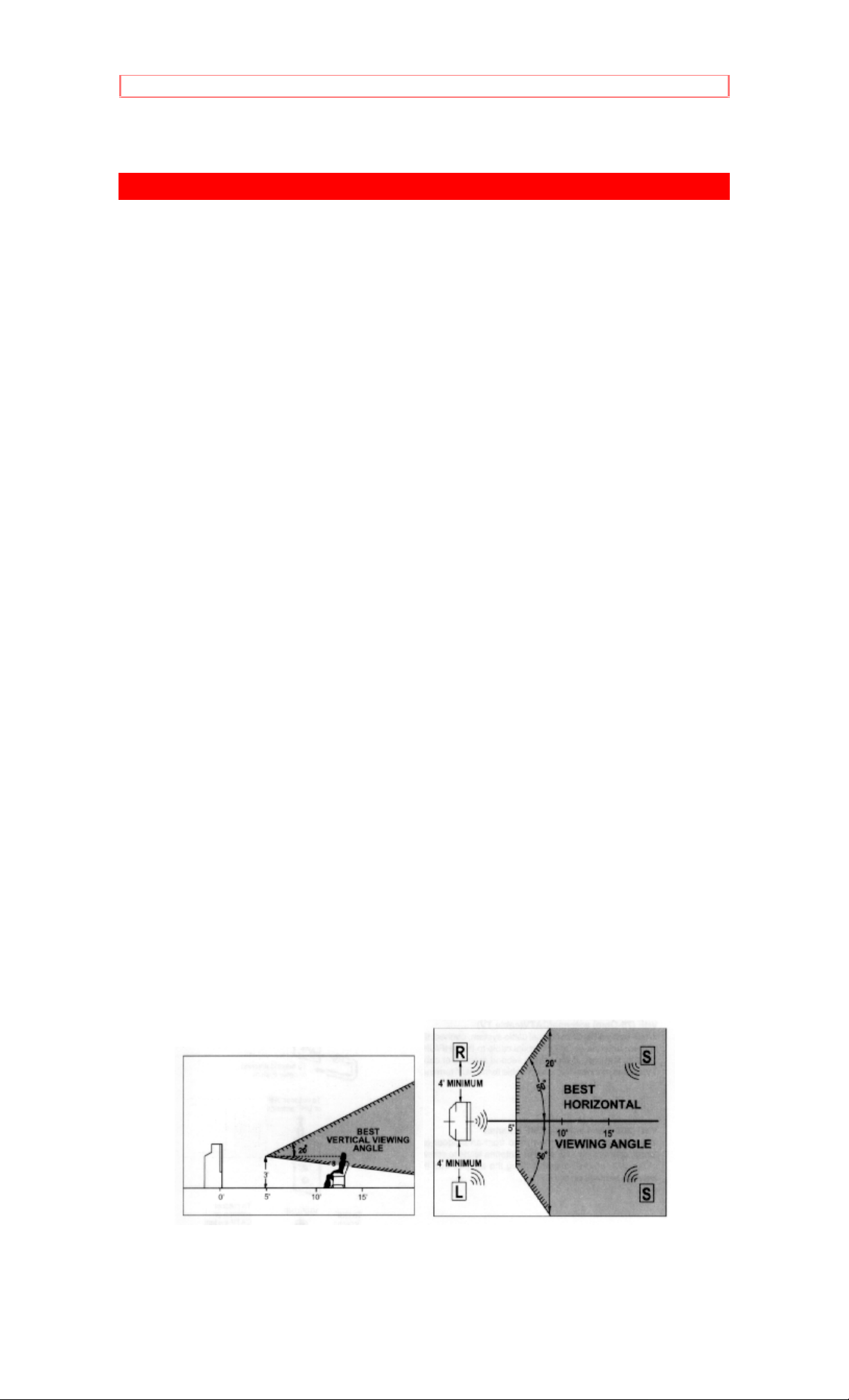
VIEWING
The major benefit of the HITACHI Projection Television is its large viewing
screen. To see this large screen at its best, test various locations in the
room to find the best spot for viewing. The drawings give several
suggestions.
The best picture is seen by sitting directly in front of the TV and about 10
to 18 feet from the screen. Picture brightness decreases as the viewer
moves to the left or right of the receiver.
During daylight hours, reflections from outside light may appear on the
screen. If so, drapes or screens can be used to reduce the reflection or
the TV can be located in a different section of the room.
If the TV's audio output will be connected to a Hi-Fi system's external
speakers, the best audio performance will be obtained by placing the
speakers equidistant from each side of the receiver cabinet and as close
as possible to the height of the picture screen center. For best stereo
separation, place the external speakers at least 4 feet from the side of the
TV. Place the surround speakers to the side or behind the viewing area.
Differences in room sizes and acoustical environments will require some
experimentation with speaker placement for best performance.
11
Page 12

HOW TO SET UP YOUR NEW HITACHI PROJECTION TV
CAUTION: The magnetic field of external speakers may cause
the TV picture to distort if the speakers are placed too close to the television.
Move the speakers away from the TV until there is no picture distortion.
12
Page 13
HOOK-UP CABLES AND CONNECTORS
HOOK-UP CABLES AND CONNECTORS
Most video/audio connections between components can be made with
shielded video and audio cables that have phono connectors. For best
performance, video cables should use 75-Ohm coaxial shielded wire.
Cables can be purchased from most stores that sell audio/video products.
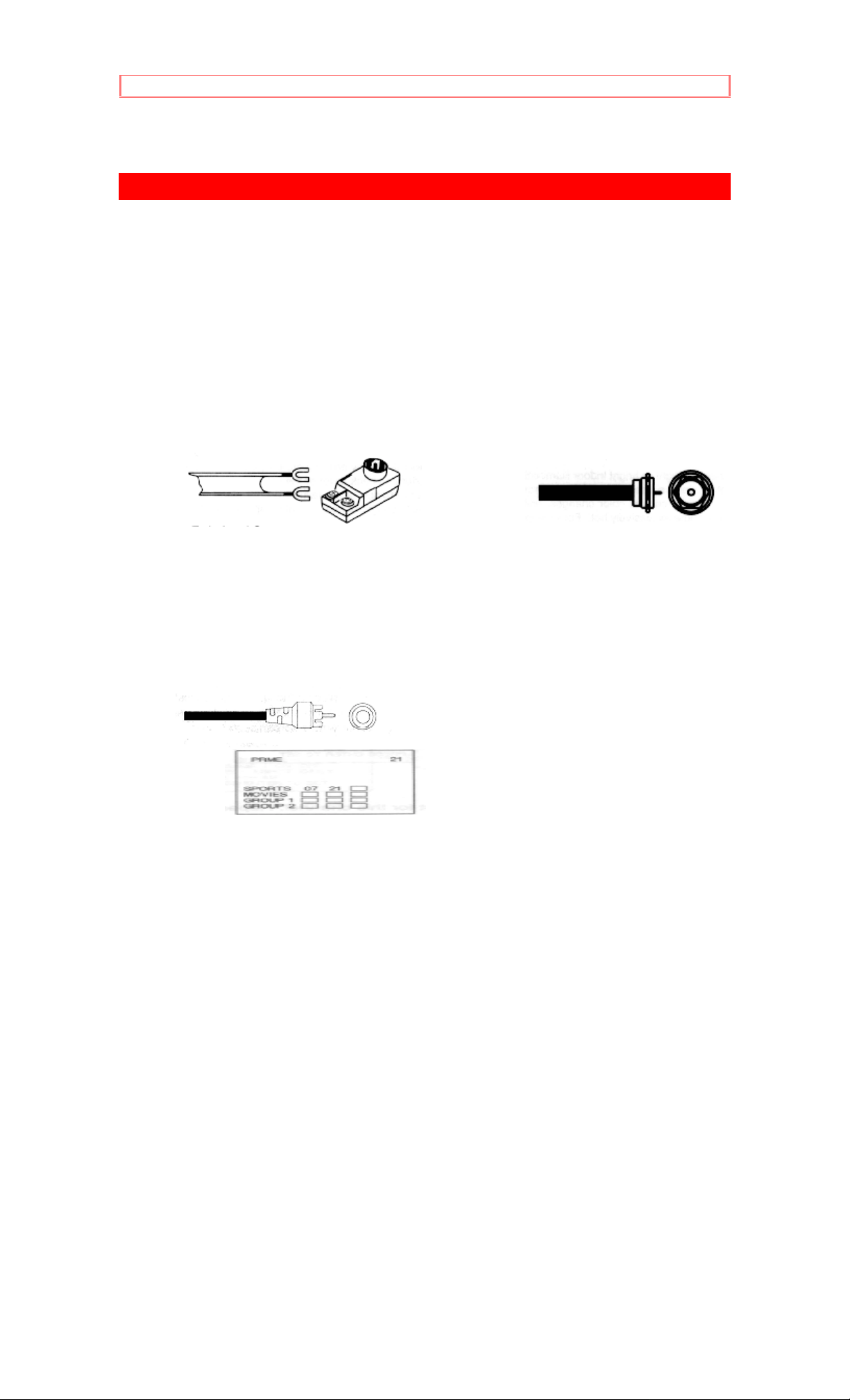
Below are illustrations and names of common connectors.
Before purchasing any cables, be sure of the output and input connector
types required by the various components. Also make sure the cables are
the correct length.
300-Ohm Twin Lead Connector "F" Type 75-Ohm
Coaxial Antenna
Connector
This outdoor antenna cable must be connected For connecting RF
signals (antenna or cable
to an antenna adaptor (300-Ohm to 75-Ohm). TV) to the antenna
jack on the television.
Phono Connector S-Video (Super Video)
Connector
Used on all standard video and audio cables which This connector is
used on camcorders, VCRs,
connect to inputs and outputs located on the and laser disc
players with an S-Video feature
Television's front and rear jack panels. in place of the
standard video cable to produce
a high-quality picture.
13
Page 14
HOOK-UP CABLES AND CONNECTORS
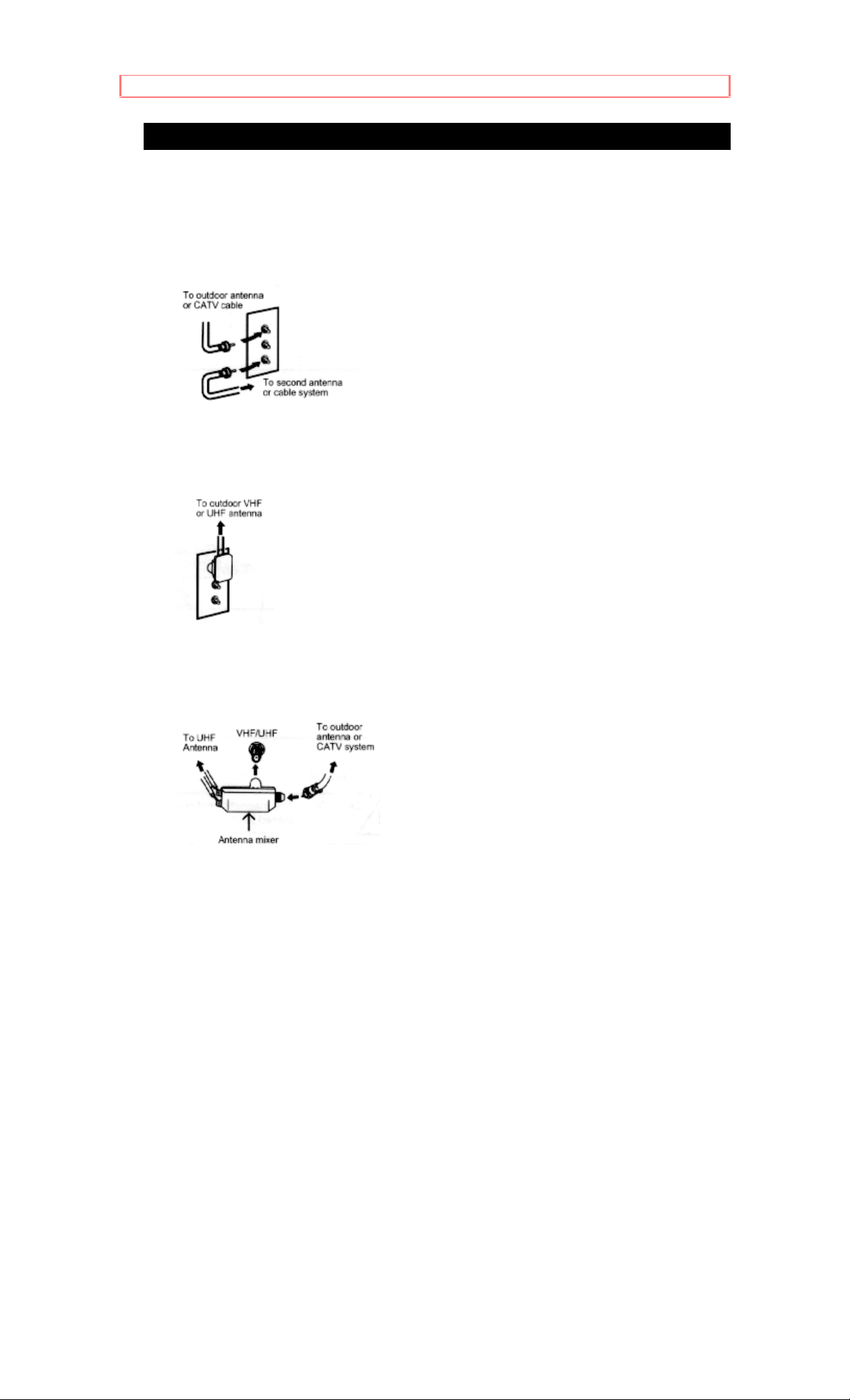
ANTENNA CONNECTIONS TO REAR JACK PANEL
VHF (75-Ohm) antenna/CATV(cable TV)
When using a 75-Ohm coaxial cable system, connect the outdoor antenna
or CATV coaxial cable to the VHF/UHF 75-Ohm terminal. If you have a
second antenna or cable TV system, connect the coaxial cable to the AUX
terminal.
VHF (300-Ohm) antenna/UHF antenna
When using a 300-Ohm twin lead from an outdoor antenna, connect the
VHF or UHF antenna leads to screws of the VHF or UHF adaptor. Plug
the adaptor into the antenna terminal on the TV.
When both VHF and UHF antennas are connected
Attach an optional antenna cable mixer to the TV antenna terminal, and
connect the cables to the antenna mixer. Consult your dealer or service
store for the antenna mixer.
14
Page 15

FRONT PANEL CONTROLS
FRONT PANEL CONTROLS
Click to see front panel diagram.
AVX (Audio/Video) selector
Press this button to select the current antenna source, VIDEO: 1, 2, or 3.
Your selection is shown in the top right corner of the screen.
VOLUME level
Press these buttons for your desired sound level. The volume level will be
displayed on the TV screen.
CHANNEL selector
Press these buttons until the desired channel appears in the top right
corner of the TV screen.
POWER button
Press this button to turn the TV on or off.
POWER light
You will see a red light when the TV is turned on.
NOTE: Your HITACHI TV will appear to be turned "off" if there is no video
input when VIDEO: 1, 2, or 3 is selected. Check the POWER On indicator to
make sure the TV is off when not in use.
AI (Artificial Intelligence) sensor
This "Artificial Intelligence" sensor will make automatic picture adjustments
depending on the amount of light in the room to give the best picture.
(See page 43)
REMOTE CONTROL sensor
Point your Remote at this area when selecting channels, adjusting
volume, etc.
V-SYNC (Vertical Hold) knob
If the TV picture "rolls" up or down, adjust this knob until you get a good
picture. This control seldom needs adjustment.
FRONT INPUT JACKS (for VIDEO :3)
Use these audio/video jacks for a "quick" hook-up from a camcorder or
VCR to instantly view your favorite show or new recording. (Press the AVX
button until VIDEO: 3 appears in the top right corner of the TV screen.)
15
Page 16

FRONT PANEL JACKS AND CONNECTIONS
FRONT PANEL JACKS AND CONNECTIONS
The front panel jacks are provided as a convenience to allow you to easily
connect a camcorder or VCR as shown in the following examples:
Click to see Front Panel Connection examples
NOTE: Completely insert connection cord plugs when connecting to front
panel jacks. If you do not, the played back picture may be abnormal. If you
have a S-VHS VCR, use the S-INPUT cable in place of the standard video
cable.
16
Page 17

REAR PANEL JACKS
REAR PANEL JACKS
Click to see Rear Panel Jacks.
Antenna Input / Output
The "ANT" button on the Genius Remote Control allows you to switch
between two separate 75-Ohm RF antenna inputs, Main (VHF/UHF) and
Auxiliary (AUX). The antenna output labeled "To converter" allows the
Main (VHF/UHF) antenna connection to pass directly to a different source
such as a pay-TV cable decoder.
Audio/Video Inputs 1, 2
The "AVX" (Auxiliary Video) button will step through each video source
and the current antenna input each time it is pressed. Use the audio and
video inputs to connect external devices, such as VCRs, camcorders,
laser disc players, video games, etc.
Output
These jacks provide fixed audio and video signals which are used for
recording.
Audio to Hi-Fi
These jacks provide variable audio output to a separate stereo system
amplifier. With this connection, the audio to the stereo can be controlled
by the television's remote control. Use these jacks for the SURROUND
Left and Right channels. (See page 15)
Rear Speaker Terminals
These terminals are used to connect external speakers, which are used
for the surround sound feature. The volume level is controlled by the
remote control main volume buttons and also by an independent rear
volume feature found in the "sound" function menu. Use speakers with 8
Ohm impedance only.
S-Video
Input 1 provides S-Video (Super Video) jacks for connecting equipment
with S-Video output capability.
17
Page 18

REAR PANEL CONNECTIONS
REAR PANEL CONNECTIONS
Click to see Rear Panel Connections.
Typical full-feature set-up. Follow connections that pertain to your
personal entertainment system.
18
Page 19
REAR SPEAKER TERMINAL CONNECTIONS
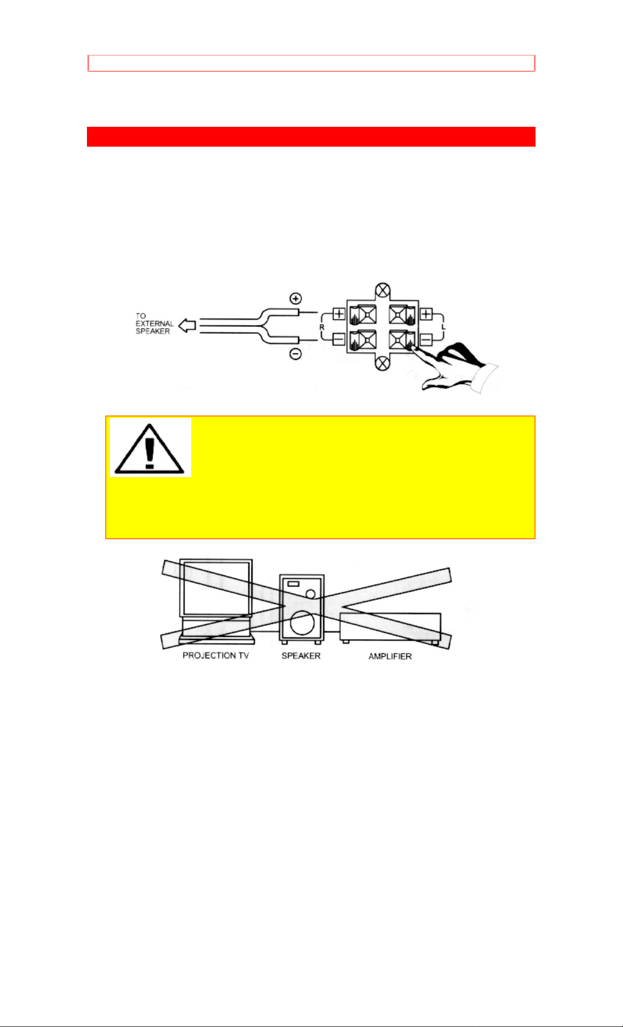
REAR SPEAKER TERMINAL CONNECTIONS
Connect after turning the power to the TV OFF.
Press the Right Speaker red button and insert the positive (+) lead wire
into the hole below the button. When the button is released, the wire is
locked into place. In the same manner, press the Right Speaker black
button and insert the negative (-) lead wire. Repeat this procedure for the
Left Speaker.
CAUTION: Do not connect Speakers simultaneously to the
REAR SPEAKER terminal of the Projection TV and an external amplifier. This
could damage both the TV and the speakers. Your TV was designed to use 8
Ohm speakers only. Any other type may degrade the audio performance of
your entertainment system.
19
Page 20

REAR SPEAKER TERMINAL CONNECTIONS
TIPS ON REAR PANEL CONNECTIONS
The S-Video connection is provided for high performance laser discs,
VCRs, etc., that have this feature. Use this connection in place of the
standard video connection if your device has this feature.
If your device has only one audio output (mono sound), connect it to the
left audio jack on the TV.
Refer to the operating guide of your other electronic equipment for
additional information on connecting your hook-up cables.
A single VCR can be used for VCR#1 and VCR#2, but note that a VCR
cannot record its own video or line output (INPUT: 1 in the example on pg.
13). Refer to your VCR operating guide for more information on the "line"
input-output connections.
20
Page 21

AUDIO SYSTEM SET-UP
AUDIO SYSTEM SET-UP
Match the numbers below to the diagram for speaker placement and refer
to the table for the surround sound requirements. (See page 47 for
SURROUND functions.)
The television's internal speakers.
These speakers are connected to a separate audio amplifier. Use the
"Audio to Hi-Fi" output on the TV.
These speakers are connected to the Rear Speaker 8 Ohm output on
the TV.
Click to see Audio System Set-Up
21
Page 22

THE REMOTE CONTROL (CLU-850GR)
THE REMOTE CONTROL (CLU-850GR)
In addition to controlling all the functions on your HITACHI Color TV, the
new Genius Remote is designed to operate different types of VCR's and
different types of CATV (Cable TV) converters with one touch. Basic
operation keys are grouped together in one area. All other controls are
separated from them and arranged in MULTI-PAGE sections, with a
display that can be switched to cover any of the four pages. Functions are
arranged and properly categorized into windows, making operation simple
when multiple functions are to be controlled
To operate your TV, point the Genius Remote at the remote sensor of the
TV.
To operate your VCR, point the remote at the remote sensor of the VCR.
Click here to see Remote CLU-850GR
READY indicator light
Refer to Page 26.
SEND/LEARN indicator light
Refer to Page 26.
LEARN/USE select switch
(Located on rear side of remote control)
LEARN......Enters the Learning mode. (Refer to page 26.)
USE...........Set for normal use.
MULTI-PAGE select switch
This selects the button layout of the multi-page section of the remote
control.
MULTI-PAGE buttons
These buttons change functions as shown on page 17.
, LIGHT BUTTON
When you are in a dark room, press this button on the side of the remote
to light up the buttons shown in . The light will stay on for about 8
seconds if no button is pressed. The buttons will not appear to light if the
room is too bright.
22
Page 23

MULTI-PAGE WINDOWS
MULTI-PAGE WINDOWS
Click to see the Multi-Page Windows of the Remote.
23
Page 24

HOW TO USE THE REMOTE TO CONTROL YOUR TV
HOW TO USE THE REMOTE TO CONTROL YOUR TV
POWER button
Press this button to turn the TV set on or off. If an automatic message is
set, it will be displayed when the TV is first turned on. (See page 41.)
RECALL button
When you want to check the channel being received, or if it has a stereo
(ST) or second audio program (SAP), press the RECALL button.
You can check the time, and if the ON TIME or OFF TIME has been set.
(See page 40.)
You can also use the RECALL button to quickly clear many of the other
on-screen displays.
Click to see the Remote.
ANT button
Use the ANT (Antenna) button to select between the VHF/UHF and AUX
(Auxiliary) antenna inputs.
NOTE: When VHF/UHF is selected, the channel number in the upper right
corner of the screen is green. When the AUX input is selected, the channel
number is in yellow.
MENU, ENTER, CURSOR buttons
All the on-screen display features can be set or adjusted by using these
buttons.
The "MENU" button will start or exit the on-screen display.
The "CURSOR" buttons will highlight functions or adjust different fea tures.
24
Page 25

HOW TO USE THE REMOTE TO CONTROL YOUR TV
These buttons are also used for FAVORITE CHANNELS. (See page 35)
The "ENTER" button will set fe a t ures to your preference.
"CHANNEL SELECTOR" buttons are used to set the time, for channel
memory, etc..
CHANNEL SELECTOR buttons
Enter two or three numbers to select channels. Enter a "0" first for
channels 1 to 9. Use the "100" button for channels 100 and higher.
Channel selection may also be performed by pressing channel up ( ) or
down ( ).
NOTE: The TV may not receive some channels if you are not in the correct
AIR/CABLE mode. (See page 32)
AVX button
The AVX (Auxiliary Video) button will select between the antenna signal
and the three sets of video input jacks each time the button is pressed. If
the Picture-in-Picture (PIP) is on, the A VX will select between the three
sets of video input jacks. (See page 21)
VOLUME, MUTE buttons
Press the "VOLUME" up ( ) or down ( ) button until you obtain the
desired sound level.
To turn the sound off instantly to answer the telephone, etc., press the
"MUTE" button. Press the "MUTE" button again or press the "VOLUME"
up ( ) button to restore the sound.
The word "MUTE" will remain displayed if the CLOSED CAPT ION feature
is turned off.
The word "MUTE" will not be displa yed if the CLOSED CAPTION f eature
is on.
25
Page 26

HOW TO USE THE REMOTE TO CONTROL YOUR TV
LAST CHANNEL (LST-CH) button
Use this button to select between the last two channels viewed. (Good for
watching two sporting events, etc.)
PICTURE-IN-PICTURE buttons
See separate section on page 21 for a description.
26
Page 27

PICTURE-IN-PICTURE (PIP)
PICTURE-IN-PICTURE (PIP)
The Picture-in-Picture feature is convenient when you want to watch more
than one program at the same time. You can watch a TV program while
viewing a VCR program (TV or tape) on any of the video inputs.
PIP BUTTON
Press the "P IN P" button and a sub-picture appears in one corner of the
screen. Press the button a second time to remove the sub-picture from
the screen. Press the AVX button when the sub-picture is on to change
between VIDEO: 1, VIDEO: 2 and VIDEO: 3. The TV channel will always
be either the main picture or the sub-picture.
EXCHNG (EXCHANGE) BUTTON
If you wish to switch what is being shown on the main picture to the subpicture, press the "EXCHNG" button.
SHIFT BUTTON
To move the sub-picture to another corner, press the "SHIFT" button. The
sub-picture moves one step counter-clockwise every time the "SHIFT"
button is pressed.
FREEZE BUTTON
If you wish to freeze the sub-picture, press the "FREEZE" button. This is
27
Page 28

PICTURE-IN-PICTURE (PIP)
convenient when trying to write down the address for a mail order
company, recording statistics for a sporting event, etc. To return the
picture to motion, press the button again.
STROBE FREEZE
Press this button without a sub-picture to freeze one or four frames of the
picture you are currently viewing. Press this button again or PIP to return
to normal viewing. The four frame strobe freeze is useful for viewing a
moving picture that has many details, for example, a close play in a
sporting event or a golf swing.
CAUTION: A pattern burn may develop if the sub-picture is left in the
same corner permanently. If the PIP feature is used frequently, occasionally
shift the sub-picture to a different corner.
NOTE:
1. Only sound from the main picture can be heard.
2. P-IN-P will not work with a CHILD LOCK channel as the Main Picture but it
will be displayed as a Sub-Picture.
3. The Sub-Picture will not appear while a FAVORITE CHANNEL is being
selected. The Sub-Picture will reappear after the FAVORITE CHANNEL
display is gone.
4. Each strobe freeze frame is delayed about 0.1 (1/10) second.
28
Page 29

USING THE REMOTE TO CONTROL VCR FUNCTIONS
USING THE REMOTE TO CONTROL VCR FUNCTIONS
Operating the pre-coded function for your VCR
This Genius Remote is designed to operate different types of VCRs. You
must first program the Genius Remote to match the remote system in your
VCR. (Refer to Table 1 on page 25).
1. Set the MULTI-PAGE select switch to "VCR".
2. Set the USE/LEARN mode select switch on the rear side of the Genius
Remote to "USE."
3. Turn ON your VCR.
4. Aim the Genius Remote control at the front of your VCR.
5. While holding down the SELECT button, press the button that matches
your VCR as shown on page 25. Continue to hold down both buttons. The
channels of the VCR will begin changing when the correct button is
pressed. When this occurs, the Genius Remote Control is programmed for
your VCR. If the VCR channels do not change after 5 seconds, try a
different Genius Remote button.
6. Release both buttons when the VCR starts to change channels. The
Genius Remote will now control your VCR.
Click here to see the CLU-850GR in the VCR position.
NOTES:
1. If your VCR cannot be operated after performing the above procedures,
this means that your VCR's codes have not been precoded into the GENIUS
REMOTE. Please store your VCR codes in memory by using the USER
mode. (Refer to page 26.)
2. The GENIUS REMOTE CONTROL will remember the codes you have
programmed in until the batteries are removed from the GENIUS REMOTE
CONTROL. After replacing the batteries repeat the entire programming
procedure stated above.
3. If you have a play back only VCR (no CH UP/DOWN function), please
follow operating step 5 described above and then check a VCR function until
you find the button that will allow the precoded VCR buttons to operate your
VCR.
PRECODED VCR BUTTONS
These buttons always transmit the chosen precoded VCR codes.
SELECT BUTTON
This is for setting up the Genius Remote to transmit the VCR's remote
codes.
EXCLUSIVE TV BUTTONS
These buttons are for operating the TV.
29
Page 30

USING THE REMOTE TO CONTROL CABLE BOX FUNCTIONS
USING THE REMOTE TO CONTROL CABLE BOX FUNCTIONS
Operating the pre-coded function for your Cable Box
This Genius Remote is designed to operate different types of cable boxes.
You must first program the Genius Remote to match the remote system in
your cable box. (Refer to Table 2 on page 25).
1. Set the MULTI-PAGE select switch to "CATV".
2. Set the USE/LEARN mode select switch to "USE."
3. Turn ON your cable box.
4. Aim the Genius Remote control at the front of your cable box.
5. While holding down the SELECT button, press the button that matches
our cable box as shown on page 25. Continue to hold down both buttons.
The channels of the cable box will begin changing when the correct button
is pressed. When this occurs, the Genius Remote Control is programmed
for your cable box. If the cable box channels do not change after 5
seconds, try a different Genius Remote button.
6. Release both buttons when the cable box starts to change channels.
The Genius Remote will now control your cable box.
Click here to see the CLU-850GR in the CATV position.
NOTES:
1. If your cable box cannot be operated after performing the above
procedures, this means that your cable box codes have not been precoded
into the GENIUS REMOTE. Please store your cable box codes in memory by
using the USER mode. (Refer to page 26.)
2. The GENIUS REMOTE CONTROL will remember the codes you have
programmed in until the batteries are removed from the GENIUS REMOTE
CONTROL. After replacing the batteries repeat the entire programming
procedure stated above.
PRECODED FOR CABLE BOX
These buttons always transmit the chosen precoded CATV codes.
SELECT BUTTON
This is for setting up the cable box's Pre-code.
EXCLUSIVE TV BUTTONS
These buttons are for operating the TV.
30
Page 31

VCR AND CABLE BOX CODES
VCR AND CABLE BOX CODES
TABLE 1. VCR Precoded remote controls
Press SELECT and this
VCR BRAND button
Audio Dynamics VOLUME
Canon 6
Citizen 0
Craig VOLUME
Curtis Mathis 2 / 6
dbx VOLUME
Dimensia 2
Emerson 100/ENTER
Fisher VOLUME
GE 2 / 6
Goldstar 0
Hitachi 1
Instant Replay 6
JC Penny 1 / 6 / 9 / VOLUME
JVC 0 / VOLUME
Kenwood 0 / VOLUME
Magnavox 4 / 6
Marantz 9 / VOLUME
Marta 0
Memorex 6 / VOLUME
MGA 7
Minolta 1
Mitsubishi 7
Montgomery Wards CHANNEL
NEC 9 / VOLUME
Panasonic 6
Pentex 1
Philco 4 / 6
Philips 4 / 6
Pioneer 1
ProScan 2
Quasar 6
RCA 1 / 2
Realistic 6 / 9 / CHANNEL / VOLUME
Sanyo 9 / VOLUME
Scott 7 / 8
Sears 1 / 9
Sharp CHANNEL
Sony 5 / MUTE / AVX
Sylvania 4 / 6
Tashiko 0
Technics 6
Toshiba 1 / 8
Vector Research VOLUME
Video Concepts VOLUME
Wards CHANNEL
Yamaha 0 / VOLUME
Zenith 3 / 5
31
Page 32

VCR AND CABLE BOX CODES
TABLE 2. Cable Box Precoded remote controls
Press SELECT and this
CATV brand button
General Instrument 0 / 1 / 2 / 3
Hamlin 4
Jerrold 1 / 2 / 3 / 3
Magnavox 9
Panasonic 8
Philips 9
Pioneer 7
Regal 4
Scientific Atlantic 6
Viewstar 9
Zenith 5
32
Page 33

USING THE GENIUS REMOTE TO LEARN ADDITIONAL FUNCTIONS
USING THE GENIUS REMOTE TO LEARN ADDITIONAL FUNCTIONS
The Genius Remote is equipped with a learning function which allows it to
learn additional infrared control codes. This remote will not only control the
television, a VCR, and a cable box, but also other electronic equipment
which uses an infrared remote transmitter, by learning the transmitter's
codes.
Only infrared remote control codes can be stored in memory.
Before starting the memory operation
Since the infrared signals sent from the remote transmitter may be
reflected by a wall, door, etc., even if the transmitter is not pointed directly
at the device, it may operate. When storing the remote control codes of
another device, turn OFF the power of the device (VCR, Cable Converter,
etc.)
If you do not do this, the device may work unexpectedly. The power could
be turned ON, an important tape could be erased, the volume could
increase too much, etc..
Click to see CLU-850GR in the USER position
LEARNABLE BUTTONS
These buttons can "learn" the codes of other remote control transmitters
when the MULTI-PAGE select switch is set to the "USER" mode.
MULTI-PAGE keys (A through L): No codes have been factory stored to
these keys.
Learning buttons other than MULTI-PAGE buttons: the codes for the TV
have been stored in memory. However, the remote control codes of other
equipment (cable converter, audio equipment, etc.) can be stored using
the learning function as shown on page 27, 28.
EXCLUSIVE BUTTONS
These buttons are for operating the TV.
Storing Operation
Set the remote transmitter as shown below.
Put the remote transmitter which contains the codes to be stored and the
GENIUS REMOTE transmitter to face each other. (Distance should be 2 4 inches.)
Set the LEARN/USE mode select switch located on the back of the
Genius Remote to the LEARN position.
33
Page 34

USING THE GENIUS REMOTE TO LEARN ADDITIONAL FUNCTIONS
Set the MULTI-PAGE select switch to "USER" position.
Press one of the learnable buttons on the Genius Remote, ("7" in this
example). This button will be used to store the new code. The READY
indicator will flash at this time. (The light will remain lit for approximately
15 seconds. If no other function is performed at this time, the operation is
canceled.)
The Genius Remote is ready to receive an infrared code from another
remote.
Press and hold the button down on the other transmitter which contains
the code to be stored, while the READY light is flashing on the Genius
Remote. Release the button after both the READY and LEARN indicators
light and then go OFF.
When storing has been performed correctly, the LEARN indicator lights for
about 2 seconds.
If the storing was not done correctly, or the codes are too long to learn, or
no more codes can be stored in memory due to memory overflow, the
LEARN indicator and READY indicator will flash ON and OFF.
Set the LEARN/USE mode select switch on the back of the Genius
Remote to "USE" and check that the button to which the code is stored
operates correctly. If it does not operate correctly, repeat from step 1.
Repeat steps 3 to 5 to store other keys.
To clear the stored codes from the USER mode
Set the MULTI-PAGE select switch to the USER mode and LEARN/USE
mode select switch to "LEARN". Then, press the POWER and the MUTE
buttons simultaneously for 3 seconds. The "READY" and "LEARN" LEDs
will light together. All MULTI-PAGE KEYS with codes are reset to their
initial states.
To remember stored codes, it is convenient to paste the labels (user's
label) provided on the buttons for the USER page. If the correct labels are
not provided, it is possible to write these letters on an empty label with a
ballpoint pen.
Example of User's Labels
NOTE:
1. To operate your TV, be sure to point the Genius Remote at the remote
sensor on the television. To operate other electronic equipment like a VCR,
point the remote at the sensor on the device.
2. Refer to the instruction manual of the VCR for operation on the buttons
exclusively for the VCR.
34
Page 35

USING THE GENIUS REMOTE TO LEARN ADDITIONAL FUNCTIONS
3. Be sure to keep the original remote transmitter even after storing its codes
in the Genius Remote Control.
4. If the Genius Remote is left with its batteries removed, the learned codes in
its memory are erased and will have to be reprogrammed into the memory.
5. The Genius Remote Control may not be able to learn certain special
remote codes.
CAUTION ON BATTERIES:
1. The Genius Remote Control is working when the LEARN indicator lights up
when a button is pressed.
2. When you press a button and the learn indicator will not light up or if the
operation is extremely slow, this is an indication that the batteries should be
replaced.
3. Even if the batteries seem dead, do not remove them until you have
replacement batteries ready to put in. The codes stored in memory will be
erased in a few minutes without power. When replacing batteries, prepare the
new ones first.
35
Page 36

EASY GRAPHIC GUIDE
EASY GRAPHIC GUIDE
Press MENU on the remote control to display the different features on
your HITACHI TV. The f eature to be selected will be highlighted in a
magenta (purple) color.
Press the CURSOR buttons to highlight a different fe ature.
Press ENTER on the remote control to select a feature.
NOTE: Press the CURSOR buttons f irst to view FAVORITE CHANNELS (See
Page 35.)
AIR/CABLE Select antenna or cable TV.
AUTO PROGRAM First time setup for channel buttons.
CHANNEL MEMORY Channel buttons, add or skip.
CLOSED CAPTION Feature to display dialogue/text.
Return video and audio adjustments to factory settings.
CHANNEL CAPTION Label channels PAY1, ABC, etc.
CHILD LOCK Block channel picture & sound.
36
Page 37

EASY GRAPHIC GUIDE
PROGRAM LIST Check channel name, scan, child-lock.
VOLUME CORRECTION Lower volume on selected channels.
CLOCK SET Set before using timer features.
ON/OFF TIMER Turn TV on or off one time or daily.
AUTOMATIC MESSAGE 1 Set for one time or daily.
AUTOMATIC MESSAGE 2 Set for one time or daily.
PREFERENCE ADJUST Adjust color, brightness, etc..
PREFERENCE SETTING Improve picture performance.
CONVERGENCE ADJUST Match red, green, and blue colors to make
white.
PREFERENCE ADJUST Adjust balance, bass, and treble.
PREFERENCE SETTING Improve sound performance.
SURROUND Special sound effects.
37
Page 38

SET UP
SET UP
Select SET UP when setting your TV up for the first time. Use the
CURSOR UP/DOWN b uttons on the remote to h ighlight the function
desired.
AIR/CABLE
Select AIR if you are using an indoor or outdoor antenna. Select CATV if
you have cable TV.
Press the CURSOR buttons to highlight the correct AIR/CABLE mode and
press MENU to exit.
Your choice will be shown on the display.
Reception channels for each mode are shown at the left.
Refer to your cable or TV guide for channel identification standards.
If certain CATV channels are poor or not possible in the CATV1 mode, set
AIR/CABLE to CATV2.
AUTO PROGRAM
This feature will automatically store active TV channels in CHANNEL
MEMORY. This will allow you to skip over unused channels when using
the CHANNEL UP ( ) or DOWN ( ) buttons.
38
Page 39

SET UP
If the MENU button is pressed while the auto programming function is
engaged, programming will stop. If two antennas are connected, switch
antenna inputs with the ANT button and repeat auto programming for the
second antenna input.
Remember to select the correct AIR/CABLE mode before using auto
programming for the second antenna input.
See CHANNEL MEMORY to add or erase additional channels.
CHANNEL MEMORY
Use this function after AUTOPROGRAM to add or erase additional
channels to the remote control CHANNEL ( ), ( ) buttons. Your choice
will be highlighted magenta.
Add or erase additional channels while still in CHANNEL MEMORY using
the CHANNEL , buttons or number buttons and then add or erase
using the CURSOR , buttons.
CLOSED CAPTION
Closed captions are the dialogue, narration, and/or sound effects of a
television program or home video which are displayed on the TV screen.
Your local TV program guide denotes these programs as or .
The selected fu nction will be magenta. Your ch oice for the func tion will be
blue.
DISPLAY: ON/OFF is to turn the cc display on or off.
MODE: C.C. (Closed Caption) is for the program you are viewing.
MODE: TEXT is for additional information such as news reports or a TV
program guide. This information covers the entire screen and viewing the
TV program is not possible. TEXT may not be available with every
program.
CHANNEL: 1 is used for the primary language (usually English).
CHANNEL: 2 is sometimes used for a second language (may vary by
region).
39
Page 40

SET UP
Use the CURSOR or to highlight the function to change, press
ENTER to change the function, and press MENU to exit.
C.C. Selected Text Selected
NOTE: The word MUTE will not be displayed if the DISPLAY is ON. If you do
not have sound, make sure MUTE is not set.
40
Page 41

FAVORITE CHANNELS
FAVORITE CHANNELS
The FAVORITE CHANNELS function will allow you to select up to 16
favorite channels by pressing the cursor buttons.
Use the CHANNEL , or number buttons to select one of your favorite
channels.
Use the CURSOR buttons to select the location (in magenta colo r) for
your favorite channel.
Press ENTER to save the channel location.
Enter channel 00 to erase a favorite channel.
Highlight ACTION and press ENTER to use your favorite channels.
Use the CURSOR buttons to highlight a favorite channel and the TV will
automatically tune to the channel.
Highlight CH SET and Press ENTER to add or erase more favorite
channels.
FAVORITE CHANNEL PREVIEW
Highlight a topic - MOVIE, SPORT, NEWS, or CHOICE and press ENTER
to get a preview of the channels under that topic. The channels will be
displayed for about 15 seconds.
NOTES:
Only the main channel viewed will have a moving picture.
Use the cursor to change the channel and moving picture for the Favorite
Channel Preview.
The Favorite Channel Preview is removed when the cursor , is pressed.
41
Page 42

RESET
RESET
Use the reset to change your preferred video and audio
adjustments to factory settings.
NOTE: This RESET Selection will not change your preferred adjustments. To
change back to your adjustments, see VIDEO (Page 42) or AUDIO (Page 45).
42
Page 43

PROGRAM
PROGRAM
This selection contains a dvanced features which will
make TV viewing easier and more enjoyable.
CHANNEL CAPTION
Use this feature to give channel names to up to 30 channels for each
antenna source.
Press the CURSOR , to select letters.
Press the CURSOR , to change position.
Press ENTER to set the CHANNEL CAPTION and it will appear in the top
left corner of the screen.
Press CHANNEL , or the number buttons to select and label
additional channels.
Press MENU to exit.
The (*) represents a blank space.
Select CANCEL to erase a CHANNEL CA PTION.
PROGRAM LIST
This function allows you to view which channels are labeled in CHANNEL
CAPTION (NAME), which have been added to CHANNEL MEMORY
(SCAN), and are protected by CHILD LOCK (LOCK).
Press CURSOR , to review more channels.
Press MENU to EXIT.
2
CHILD LOCK
This function will block out the picture and sound of the selected channel.
43
Page 44

PROGRAM
The code to set or cancel CHILD LOCK is a three digit key number. The
factor preset key number is 000.
The picture and sound will now be blocked out for this channel. Repeat
the same steps to cancel the CHILD LOCK.
To change the key number, select key number change. Enter the old
number (factory preset 000 for first time use), then enter a new three digit
key number you prefer.
If you forget your key number, use the factory code 777 to erase your key
number. This will reset the key number back to the factory preset 000.
VOLUME CORRECTION
Use this function to reduce the volume level of up to four TV channels that
sound loud compared to other TV channels.
Press the CURSOR , to select one of the four volume corrections.
Use the Channel , or number buttons to select a channel.
Press ENTER to set the channel.
Press the CURSOR , to adjust volume level.
Press MENU to exit.
NOTE:
1. VOLUME CORRECTION adjustment is for the channel displayed in the top
right corner of the screen. To adjust a different channel, you must select the
channel with the channel or number buttons and press ENTER.
2. If the channel has been corrected before, use the cursor , to highlight
that channel then use the cursor , to change the level.
3. To erase a channel from the volume correction, select channel 00 and
press ENTER.
4. The volume level will change from 50% to 100% in 5% steps.
44
Page 45

CLOCK
CLOCK
Use this feature for all time related function.
CLOCK SET
The time must be set before you can use the on/off timer or automatic
message.
Use the NUMBER buttons and CURSOR , to set the time.
The AM or PM selected will be h ighlighted in blue.
ON/OFF TIMER
This function will automatically turn the TV on or off, one time only or
everyday.
The selection to change will be in magenta.
Press the number buttons to select the time the TV will turn on or off. (A M:
1, PM: 2)
Press the CURSOR , buttons for MODE: ONCE (one time only) or
MODE: DAILY (TV will turn on/off at the same time e very day).
Press CHANNEL , or the NUMBER buttons to set the channel the
TV will tune to when it automatically turns on.
Your choice for AM/PM and MODE will appear in blue.
Press ENTER to start.
Select CANCEL and press ENTER to erase times.
NOTE: You can set either ON TIME only, OFF TIME only, or both. The mode
will be the same for bot h.
CAUTION: Do not use your TV as a deterrent when away from
home by using both the ON and OFF TIMERS. For safety, the TV should be
turned off when you are away from home.
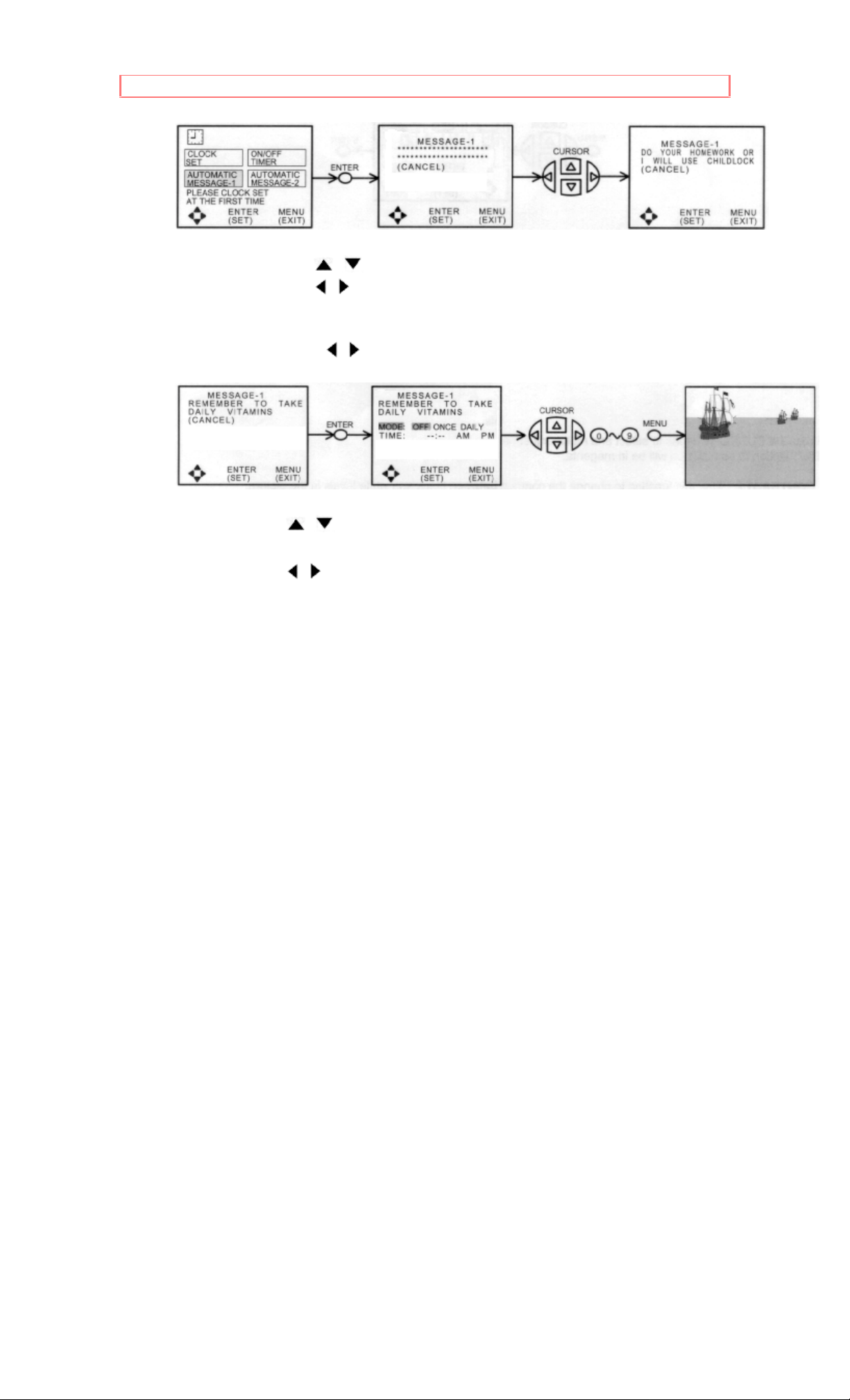
AUTOMATIC MESSAGE
Use this function to set one or two personal message once a day or one
time only.
45
Page 46
CLOCK
Use the CURSOR , to select a letter or other character.
Use the CURSOR , to change position.
Press ENTER when message is finished.
The asterisk (*) represents a blank space.
Move the CURSOR , until (CANC EL) i s mag enta and pr ess ENTER to
erase message.
Use CURSOR , to choose MODE or TIME.
Use CURSOR , to set MODE when it is magenta. Your choice will be
in blue.
Use the NUMBER buttons to set the time.
Press ENTER to start and MENU to exit.
46
Page 47

VIDEO
VIDEO
Select VIDEO to adjust picture settings, improve picture
quality and to adjust convergence.
PREFERENCE ADJUST
Use this feature to adjust contrast, color, etc.
Press the CURSOR buttons to select and make adjustments.
The function to be adjusted will be in magenta .
CONTRAST- Use this function to change the contrast between black and
white level in the picture. This adjustment will only affect the picture when
the PICTURE SETTING AI is OFF. (See page 43)
TINT- Use this function to adjust flesh tones so they appear normal.
COLOR- Use this function to adjust the level of color in the picture.
BRIGHT- Use this function to adjust overall picture brightness.
SHARPNESS- Use this function to adjust the amount of fine detail in the
picture. This adjustment will only affect the picture when PICTURE
SETTING AI is OFF.
RESET- When RESET is selected, press ENTER to return video
adjustments to factory preset conditions.
PREFERENCE SETTING
Your HITACHI TV has an A I (Artificial Intelligence) function which will
automatically adjust picture settings to produce the highest quality picture
possible.
When AI is magenta, use the cursor , to turn the AI on or off. Your
choice will be in blue.
47
Page 48

VIDEO
Use the CURSOR , to select function.
Use the CURSOR , to turn function on or off. Your choice will be in
red.
AI (ARTIFICIAL INTELLIGENCE)
When the AI function is on, the TV's internal computer will perform the
following:
1. Automatically monitor and adjust contrast depending on room lighting
(sensor is located in the front panel), to produce a more natural picture.
2. Automatically monitor and adjust color levels and maintain natural flesh
tones.
3. Automatically compensate for weak or strong TV signals to produce a
clear picture. (The SHARPNESS function is automatically adjusted.)
Turn the AI function off to control other PREFERENCE SETTINGS.
AUTOCOLOR
The AUTOCOLOR function automatically monitors and adj usts the col or to
maintain constant color levels even after a program or channel changes.
It also maintains natural flesh tones while preserving fidelity of background
colors. For best picture performance leave the AUTOCOLOR function on.
NOISE REDUCER
The NOISE REDUCER automatically reduces conspicuous noise in the
picture without degrading picture quality.
SUPER CONTR (SUPER CONTRAST)
Turn on SUPER CONTR to improve picture detail in areas of high
brightness.
CONVERGENCE ADJUST
Your Projection TV has three color projection tubes: one for red, one for
green, one for blue. When mixed together in the proper proportion, the
output of these three color tubes can produce any color. To produce
these colors, however, the beams must be precisely aligned over each
other so that the colors can be mixed. The process of aligning these
picture beams is called "convergence".
Over a period of time, the picture tubes can drift out of alignment due to
normal bumps and vibrations or moving the TV. If you move your TV, or
if, after a time, you notice color rings or halos around objects in the
picture, you may want to converge (align) the colors.
To simplify convergence, the following feature allows you to display a test
pattern of horizontal and vertical lines on the screen. Properly converged,
the lines appear white, which is actually a combination of the outputs of
the three color tubes. The output of the green tube is stationary. The
outputs of the red and blue tubes can be adjusted. When properly
aligned, the outputs of all three tubes should be directly over each other to
produce the white lines.
48
Page 49

VIDEO
Press the CURSOR
, to move the color displayed up or down.
Press the CURSOR , to move the color displayed left or right.
Press ENTER to change the color.
Press MENU to exit.
NOTE: If the 60SX8B/9K or 50SX6P is unplugged from the wall outlet or
there is a power loss, CONVERGENCE may appear to be misadjusted. Wait
30 seconds after the set is plugged in or power returns before turning the set
on.
49
Page 50

AUDIO
AUDIO
Select AUDIO to adjust the TV to your preference, to
improve the sound quality, and to select special sound effects.
PREFERENCE ADJUSTMENT
Use this to set balance, bass, and treble.
Press the CURSOR buttons to select and make adjustments. The
function to be adju sted will be in magenta.
BALANCE- This function will control the left and right balance of the TV
internal speakers, the AUDIO TO HI-FI output, and the surround speaker s.
The balance control is also found in the TEST TONE function (See page
48.)
BASS- This function controls the low frequency audio to all speakers.
TREBLE- This function controls the high frequency audio to all speakers.
RESET- When RESET is selected, press ENTER to return audio
adjustments to factory preset conditions.
PREFERENCE SETTING
Use PREFERENCE SETTING to improve the sound performance of your
TV depending on listening conditions.
Use the CURSOR , to select a function. The function will be in
magenta.
Use the CURSOR , to change a function. Your choice will be in blue.
50
Page 51

AUDIO
MTS MODE (Multi-Channel Television Sound) will allow you to select
STEREO (a stereo broadcast), SAP (second audio program) which may
be a secondary language, weather report, etc. or MONO (monaural
sound) used when receiving a weak stereo broadcast.
The sources received will be displayed below the cha nnel number. The
source you select will be displayed to the left of the channel number. See
example below for each selection when both stereo and second audio are
received (monaural is always received).
DYNAMIC BASS
This function allows you to enjoy spectacular bass sound that would
normally be heard only with expensive home speaker systems.
LOUDNESS
This function will improve the quality of both low and high frequency
sounds when listening at low volume levels.
INT. SPEAKERS
This function is useful when first setting up the external speakers, or if you
prefer to use only speakers from a separate stereo system.
SURROUND
The following surround settings will reproduce the "live" sound you would
hear in concert halls, sports stadiums, movie theaters, etc. when you set
up your speaker system as shown in the section on rear panel
connections on pages 13-15. The surround sound system is most
effective with movie and other stereo material that is Dolby Surround
encoded, and played on a stereo VCR.
Use the CURSOR buttons to select surround setting and to select and
adjust the volume of front and rear speakers. Front volume also controls
AUDIO TO HI-FI. Adjust front volume first.
Each surround setting has separate front & rear volume controls. PRO
LOGIC also has a center volume when CENTER MODE: NORMAL is
selected.
The CENTER and REAR VOLUME will increase or decrease when
FRONT VOLUME is adjusted to keep an equal balance between the
surround channels.
The maximum volume allowed for the CENTER and REAR will depend on
how loud the FRONT volume is set.
The FRONT volume is the same as the main TV volume.
51
Page 52

AUDIO
SURROUND OFF
Use this for normal stereo/mono broadcasts.
MATRIX SURROUND
Listener is surrounded by many sound sources such as a sporting event,
etc.
NOTE: Some TV systems do not transmit optimum audio channel separation
which can reduce the effectiveness of the MATRIX SURROUND function.
HALL SURROUND
Resonant sound - Listener has the feeling of being in a concert hall.
PRO LOGIC
Dolby Pro Logic provides four separate sound channels: left, center, right
and surround. For a properly encoded program marked
the center sound channel contains the dialogue for the
program viewed. The left and right channels produce sound effect that will
match the action on the TV screen. For example, Dolby Pro Logic will
enhance the effect of a car viewed driving from the left side of the TV
screen to the right side. The surround channel (speakers) are placed
behind the viewing area to add additional spatial sound effects.
To fully benefit from Dolby Pro Logic Surround, it is recommended that the
surround speaker system be complete as shown on page 15.
Use the CURSOR buttons to select the surround function.
MODE
Can be set to 3CH LOGIC or PRO LOGIC. When 3CH LOGIC is set, the
CENTER MODE will automatically be set to NORMAL. 3CH Logic
prevents loss of the surround channel sound by splitting it between the left
and right speakers from a separate audio amplifier.
CENTER MODE
This can be set to NORMAL or PHANTOM when using the MODE: PRO
LOGIC. PHANTOM center mode prevents loss of center channel sound by
splitting it equally to the left and right TV speakers.
TEST TONE
A test sound is generated allowing the listener to balance volume from
each channel. Adjust the volume levels until all channels are equal.
Use the CURSOR buttons to select and adjust VOLUME and BALANCE.
Press MENU to exit.
NOTE: The BALANCE in T EST TONE is the same a s the BALANCE in
52
Page 53

AUDIO
AUDIO - PREFERENCE ADJUST.
53
Page 54

CARE OF YOUR HITACHI PROJECTION TV AND YOUR REMOTE CONTROL
CARE OF YOUR HITACHI PROJECTION TV AND YOUR REMOTE CONTROL
DO
Dust the screen and cabinet with a soft cloth.
Clean the screen with a soft cloth moistened in warm water. Dry with a
soft cloth. (A mild soap may be used if the screen is extremely dirty.)
Place your TV and remote control away from extreme heat, humidity and
extremely dusty places.
Remove the plug from the wall outlet if your television set will not be used
for a long period of time, for instance, when you go on vacation.
DO NOT
Do not clean your screen or cabinet with strong cleaners, polishes or
chemically treated cloth.
Do not place rubber or vinyl products or cellophane tape on your set.
Do not touch the screen too often.
Do not subject the Remote Control to shocks such as dropping it on the
floor, etc. Physical damage to the precision parts may result.
Avoid placing the Remote Control in a high humidity place or getting it wet.
Don't leave it on or near a heater. Excessive heat or moisture may cause
the unit to cease operation.
When the batteries run down, remote control operation will become erratic
or possibly stop altogether.
Replace the old batteries with four fresh "AA" size batteries.
Exposure of the viewing screen to prolonged direct sunlight or heat may
cause the screen to permanently warp, resulting in a distorted picture.
54
Page 55

RECEPTION PROBLEMS
RECEPTION PROBLEMS
IGNITION NOISE:
Black spots or horizontal streaks may appear, picture may flutter or drift.
Usually caused by interference from automobile ignition systems, neon
lamps, electrical drills and other electrical appliances.
GHOSTS:
Ghosts are caused by the television signal following two paths. One is the
direct path and the other is reflected from tall buildings, hills or some other
objects. Changing the direction or position of the antenna may improve
reception. Ghosting may also be caused by defects in the antenna
system such as unshielded leads or connecting several sets to the same
antenna without using multiple antenna couplers.
SNOW:
If your receiver is located in the fringe area of a television station where
the signal is weak, your picture may be marred by the appearance of small
dots. When the signal is extremely weak, it may be necessary to install a
special antenna to improve the picture.
RADIO FREQUENCY INTERFERENCE:
The interference produces moving ripples or diagonal streaks, and in
some cases, causes loss of contrast in the picture.
55
Page 56

CHECK HERE BEFORE CALLING FOR SERVICE
CHECK HERE BEFORE CALLING FOR SERVICE
Click here to see Troubleshooting Chart.
This Projection Television incorporates advanced power surge protection
technology designed to protect against component or circuit damage due
to external or internal voltage or power surges.
IF YOUR SET SHOULD APPEAR TO HAVE A LOSS OF POWER,
PLEASE FOLLOW THIS PROCEDURE:
1) Push the power switch (ON/OFF switch) once.
2) If there is still no power, wait 30 seconds and push the power switch
again.
3) If there is still no power, unplug the power cord from the wall. Wait
thirty seconds and plug the power cord back in. Push the power switch
again.
This protective technology should provide for years of lasting
entertainment from your Projection Television.
56
Page 57

SPECIFICATIONS
SPECIFICATIONS
Features:
Superfine Picture Quality
1000 Line Horizontal Resolution (60SX8B, 60SX9K, 50SX6P)
950 Line Horizontal Resolution (other models)
Pure Green and Red Filter Lenses
Artificial Intelligence System
Dolby Pro Logic*/Hall/Matrix 4-Way Surround Sound
Genius Remote (Controls many VCR brands, cable boxes, and other
audio/video equipment)
Easy Graphic Guide On-Screen Display
Favorite Channel Preview
Full set of Input Jacks, Including S-Video
Closed Caption Decoder
High Resolution Picture-In-Picture with Strobe Freeze
Tuned Port Bass Reflex Speakers
* Registered Trademark Dolby Laboratories
Manufactured under license from Dolby Laboratories Licensing
Corporation. Additionally licensed under one or more of the following
patents: U.S. number 3,959,590; Canada numbers 1,004,603 and
1,037,877. "Dolby", "Pro Logic", and the double-D symbol are trademarks
of Dolby Laboratories Licensing Corporation.
Inputs:
Power Input.....AC 120V, 60 Hz
Power consumption (operating)
46UX16B/17K, 50UX18B/19K.....160W
50SX6P, 60SX8B/9K....................161W
Power consumption (maximum)
46UX16B/17K, 50UX18B/19K.....230W
50SX6P, 60SX8B/9K....................240W
Antenna input impedance.....75 Ohm
Channel coverage.....181 ch.
VHF-Band.....2 ~ 13
UHF-Band.....14 ~ 69
CATV Mid Band.....A-5 ~ A-1, A-I
Super Band.....J-W
Hyper Band.....W+1 - W+28
Ultra Band.....W+29 - W+84
Video.....1.0Vp-p, 75 Ohm
S-Video
Luminance (Y).....1.0Vp-p, 75 Ohm
Chrominance (C).....0.286Vp-p, 75 Ohm
Audio input impedance.....47k Ohm
57
Page 58

SPECIFICATIONS
Average input level.....470mVrms
Maximum input level.....940mVrms
Outputs:
Video.....1.0Vp-p, 75 Ohm
Audio (fixed).....470mVrms, 1k Ohm
Dimensions:
46UX16B/17K 50UX18B/19K 50SX6P
60SX8B/9K
Height (in.) 49 1/2 51 7/8 51 7/8
60 1/2
Width (in.) 41 1/8 44 1/8 41 5/8
52 3/8
Depth (in.) 27 27 1/2 27 1/2
27 7/8
Weight (lbs.) 221 250 250
391
NOTE: Due to improvements, specifications in this operating guide are
subject to change without notice.
58
Page 59

NOTES
NOTES
(blank page)
59
Page 60

HITACHI SERVICE HOTLINE
To locate an authorized HITACHI service facility in the continental U.S.A.
DIAL TOLL FREE
7 days a week, 24 hours a day
800 HITACHI
1-800-448-2244
Hitachi Home Electronics (America), Inc.
Hitachi has made every effort to assure y ou hour s of trouble free oper ation
from your unit. However, should you require service, a network of Hitachi
Authorized Service Facilities has been established in all 50 states and
Puerto Rico. Each facility will provide you with convenient and expedient
assistance. Our service "Hotline" operator will direct you to the Hitachi
Authorized Service Facility nearest you. Just present proof of purchase
and/or delivery receipts to the Hitachi Authorized Service Facility, and
service will be rendered in accordance with the terms of the limited
warranty as stated on your warranty card or operating guide.
Should you have any questions regarding in-warranty service,
operation or technical assistance, please contact:
Hitachi Home Electronics (America), Inc
3890 Steve Reynolds Blvd
Norcross, GA 30093
Tel: 404-279-5600
Hitachi Sales Corporation of Hawaii
3219 Koapaka St.
Honolulu, HI 96819
Tel: 808-836-3621
60
Page 61

WARRANTY CARD, front
WARRANTY CARD, front
HITACHI PROJECTION TV LIMITED WARRANTY
Hitachi Home Electronics (America), Inc.
Hitachi Sales Corporation of Hawaii
Hitachi Home Electronics (America), Inc. and Hitachi Sales Corporation of
Hawaii ("Hitachi")
warrant this component in duration as stated below:
Lifetime Lens, 2 Years CRT, 1 Year Parts, 90 Days Screen, 1 Year Labor
Conditions of Hitachi Limited Warranty
Hitachi Projection TVs are warranted to be free of defects in parts and
workmanship from the time of purchase by the original owner. If this
product is found to be defective, Hitachi will repair or replace defective
parts at no charge for the parts to the original owner, subject to the
conditions of the Limit Warranty. The labor for the repair or replacement
of the defective parts will be provided by Hitachi without charge, subject to
the conditions of the Limited Warranty.
1. PARTS - The warranty periods for parts are: Lifetime for main optical
lens, 90 days on the screen, 2 years on the CRTs and 1 year on the
remaining parts from the date of original purchase. During the applicable
limited warranty period for parts, d efective parts will be replaced at n o
charge for the part. Parts used for the rep lacement will be warranted for
the remainder of the original warranty period for that part.
2. LABOR - For a period of 90 days from the date of purchase, Hitach i will
repair or replace the screen if it proves to be defective without charge for
labor. For all other parts, Hitachi will provide the labor for warranty repair
at no charge for the period of one year from date of original purchase.
Except for the screen as noted above, the labor service during this one
year period includes (at Hitachi's option) either in-home repair or free pick
up and delivery.
3. Owner must provide verification of the date of purchase when
requesting Limited
Warranty Service. (Dated Sales Receipt Required)
4. All repairs must be performed by a Hitachi Authorized Service Facility.
For information concerning repairs, operation, technical assistance or for
obtaining the location of the nearest Hitachi Authorized Service Facility or
Parts Distributor, please call the number below.
1-800-HITACHI (1-800-448-2244)
Hitachi Home Electronics (America), Inc
3890 Steve Reynolds Blvd
Norcross, GA 30093
Tel: 1-404-279-5600
Hitachi Sales Corporation of Hawaii
61
Page 62

WARRANTY CARD, front
3219 Koapaka St.
Honolulu, HI 96819
Tel: 1-808-836-3621
62
Page 63

WARRANTY CARD, back
WARRANTY CARD, back
Warranty Limitations
The Limited Warranty provided by Hitachi does not cover:
A. Antennas, cabinet, cabinet parts, knobs, batteries and accessories.
B. Screens that have been cleaned with anything other than water and a
mild soap solution.
C. Lenses from units that have been sold or transferred from the original
purchaser. Any lens element that is permanently attached to the CRT
assembly is excluded from the lifetime warranty. The labor to repair or
replace will be at no charge during the one year warranty duration. Labor
charges to repair or replace lenses found to be defective after the one
year warranty duration will not be covered.
D. Any new product purchased or service performed outside of the
continental United States or its possessions.
E. Uncrating, setup, installation, or adjustments of customer operated
controls.
F. Repairs or replacement parts supplied by other than an Authorized
Hitachi Service Facility.
G. Any defect, malfunction, or failure caused by or resulting from improper
service, maintenance, repair, or from abuse, negl ect, acci dent or any other
cause beyond the control of Hitachi.
H. Any product used for commercial or industrial purpose.
J. Any unit that has been sold or transferred from the original owner.
This limited warranty is made only to the original consumer purchaser of
this Hitachi Projection TV and is effective only upon presentation of
evidence of provable date of purchase.
NO PERSON, AGENT, DISTRIBUTOR, DEALER, SERVICE FACILITY,
OR COMPANY IS AUTHORIZED TO CHANGE, MODIFY OR AMEND
THE TERMS OF THIS LIMITED WARRANTY IN ANY MANNER OR
FASHION WHATSOEVER. EXCEPT AND TO THE EXTENT PROVIDED
IN THIS LIMITED WARRANTY, HITACHI MAKES NO EXPRESS
WARRANTY REGARDING THIS HITACHI PRODUCT. FURTHER, ALL
IMPLIED WARRANTIES RELATING TO ANY PORTION OF THIS
PRODUCT, INCLUDING ANY WARRANTY OF MERCHANTABILITY OR
FITNESS FOR A PARTICULAR PURPOSE, ARE LIMITED TO THE
DURATION OF THE APPLICABLE EXPRESS WARRANTY CONTAINED
ABOVE. HITACHI SHALL NOT BE LIABLE TO THE PURCHASER OR
TO ANY OTHER PERSON FOR A NY INCIDE NTAL OR
CONSEQUENTIAL DAMAGE OR LOSS OF PROFIT OR PRODUCT
RESULTING FROM ANY DEFECT IN OR MALFUNCT ION OR FAILURE
OF THIS HITACHI PRODUCT. SOME STATES DO NOT ALLOW
LIMITATIONS ON HOW LONG AN IMPLIED WARRANTY LASTS, OR
THE EXCLUSION OF INCIDENTAL OR CONSEQUENTIAL DAMAGES,
SO THE ABOVE LIMITATIONS MAY NOT APPLY TO YOU. THIS
WARRANTY GIVES SPECIFIC LEGAL RIGHTS AND YOU MAY ALSO
HAVE OTHER RIGHTS WHICH VARY FROM STATE TO STATE.
Important Notice:
Retain your sales receipts for warranty purposes. Please complete the
section below for your records, as it may be needed in the event of loss.
63
Page 64

WARRANTY CARD, back
HITACHI
Projection TV
Limited Warranty Registration
(For your record - Attach sales receipt to this card)
Model no.
Serial no.
Dealer Name
Date of Purchase
Dealer Address
City
State
Zip
1
Introduced in 94-95 line. Mention as current model!!!
Warranty: 1 yr Labor, 1 yr Parts, Lifetime Lenses, 90 days screen, 2 yrs CRT's.
46UX16B/17K: 950 Lines resolution, Advanced high-resolution PIP, Dolby Pro-Logic
surround sound, Ultrablack high contrast screen, Illuminated genius remote control,
Velocity scan modulation.
50UX18B/19K: 950 Lines resolution, Advanced high-resolution PIP, Dolby Pro-Logic
surround sound, Ultrablack high contrast screen, Illuminated genius remote control,
Velocity scan modulation.
50SX6P | 60SX8B/9K: 1000 Lines resolution, Advanced high-resolution PIP, Dolby
Pro-Logic surround sound, Ultrablack high contrast screen, Illuminated genius remote
control, Velocity scan modulation.
2
You can always either lock or unlock any one of the four channels using code
"777", regardless of what the key number actually is. Code "777" will always lock
or unlock each station.
64
 Loading...