

Page 1
PROJECTION COLOR TV
OPERATING GUIDE
IMPORTANT SAFEGUARDS
FIRST TIME USE
2-5
6-15
THE GENIUS REMOTE CONTROL 16-30
|1
ULTRATEC
31-65
ON SCREEN DISPLAY.
USEFUL INFORMATION INDEX
66-71
Page 2
• IMPORTANT
_rnew HITACHI COLOR TV incorporates a host of features designed to give you excellent performance if.youfollow
instructions in this manual. We recommend that you read the following instructions and "IMPORTANT SAFE-
_,RDS" notice before turning on your TV set forthe firsttime.
ow all warnings and instructions marked on this television receiver.
The lightning flash with arrowhead symbol, within an
equilateral triangle, is intended to alert the user to the
,_ RISK OF ELECTRIC SHOCK
.3AUTION:TO REDUCE THE RISK OF ELECTRIC SHOCK,
EFER SERVICING TO QUALIFIED SERVICE PERSONNEL.
I CAUTION
DO NOT REMOVE COVER (OR BACK)
NO USER-SERVICEABLE PARTS INSIDE.
DONOTOPEN
WARNING:
TO PREVENT FIRE OR SHOCK HAZARD, DO NOT
EXPOSE THIS TELEVISION SYSTEM TO RAIN OR MOISTURE,
presence of uninsulated "dangerous voltage" within
the product's enclosure that may be of sufficient
magnitude to constitute a risk of electric shock to
persons.
The exclamation pointwithin an equilateral triangle is
intended to alert the usertothe presence ofimportant
operating and maintenance (servicing) instructions in
the literature accompanying the appliance.
NOTE: • There are no user serviceable parts inside the receiver.
• Model number and serial number are Indicated on back side of the set.
'OWER SOURCE:
his HITACHI color TV is designed to operate on 120 volts 60 Hz, AC household current.
lsert power cord Into s 120 volt 60 Hz outlet.
O PREVENT ELECTRIC SHOCK, DO NOT USE THE TELEVISION'S PLUG WITH AN EXTENSION CORD,
IECEI:rTACLE, OR OTHER OUTLET UNLESS THE BLADES AND GROUND TERMINAL CAN BE FULLY
_ISERTEDTO PREVENT BLADE EXPOSURE.
lEVER CONNECT THE TV TO 50 Hz, DIRECT CURRENT, OR ANYTHING OTHER THAN THE SPECIFIED
'OLTAGE.
NOTE: Thistelevisionreceiver willdisplaytelevisionclosedcaptioning,(l'_lor I_), inaccordancewithparagraph
15.119 ofthe FCC rules.
/_CAUTION: Never removethebackcoverofthesetas thiscanexposeyoutoveryhighvoltagesandother
hazards. Ifthesetdoesnotoperateproperly,unplugthesetandcallyourdealerorserviceshop.
HITACHI's35UX60B employstate-of-the-artcomputercircuitstoenhancepictureperformance.
ShouldyourcolorTV becomeunpluggedfromtheAC walloutletorloseACpowerduetoalocal
powerfailure,pleasewaitat least30 secondsfollowing returnofpowerbeforeturningonyour
TV. This willallowthe computerstimeto check/correctany internalerrorscausedby theloss
ofpower.
2
Page 3
SAFETY TIPS
IMPORTANT SAFEGUARDS
CAUTION:
SAFETY POINTS YOU SHOULD KNOW ABOUT
YOUR HITACHI TELEVISION RECEIVER
Our reputation has been built on the quality, peflormance, and ease of service of HITACHI television receivers,
Safety is also foremost n our minds in the des gn of these units. To he p you operate these products properly this folder illustrates safety tips which will be of benefit
to you. Please read it carefully and apply theknowledge you obtain from tto the proper oparat on of your HITACH te evs on receiver.
Please fill out your warranty card at once and mail it to HITACHI. This will enable HITACHI to notify you promptly in the improbable event that a safety problem should
be discovered in your model of product.
* Read all oftheseinstructions
* Save these instructionsforlateruse.
* Followallwarningsandinstructionsmarked
onthe televisionreceiver.
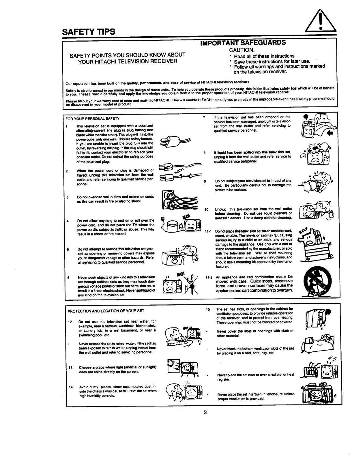
FOR YOUR PERSONAL SAFETY 7
This television set is equipped with a polanzad
eltematirvg-current line plug (a plug having one
blade wider than the other). This plug will fit intothe
pewer outlet only one way. This isa sately feature.
If you are unable to insert the plug fully into the
outlet, try reversing theplug. If the plug should still
fail to fit, contact your electrician to replace your
Obsolete outlet. Do not defeat the safety purpose
ofthepela_edplug.
When the power cord or plug is damaged or
frayed, unplug this television eel from the well
outlet and refer servicing to qualified service per-
sonnel.
3 Do not overload wall outlets and extension cords
as this can result in fire or electric shock.
Do not allow anythingto rest on or rollover the
powercord, and do not placethe TV where the
powercordis subjecttotrafficorabuse. Thismay
resultin a shock or firehazard.
Do not attempt to een_ce this television set your-
self as opening or removing covers may expose
you to dangerous voltage or other hazards. Refer
eli sendcing to qualified service personnel.
Never push ot_ of any kind into this television
set through cabinet slots as they may touch clan-
gerous veltage points or shorl out perts that cauid
result in • fire orelectric shock. Never spill liquid of
any kind on the telavislon set.
__=_:_g Do not subject your television set to impact of any
If the television set has been dropped or the
cabinet has been damaged, unplug this televismn
set from the wall outlet and refer servicing to
qualified sennce personnel.
If liquid has been splllad into this television set,
unplug it from the wall outlet and refer sennce to
qualified service personnel.
kind. Be particularly careful not to damage the
picture tube surface.
10 Unplug this television set from the wall outlet
before cleaning. DOnot use liquid cleaners or
aerosolcleaners. Use a damp clothforcleaning.
11-1 Do Ilot place this televiszon set on an unstable cart,
stand, ortable. The television set may fell, causing
serious injury to a child or an adult, and serious
damage to the appliance. Use only with a cart or
stand recommended by the manufacturer, or sold
with the television set. Wall or shelf mounting
should follow the manufacturer's instructions, and
should use a mounting kit approved by the manu-
facturer.
tt-2 An _iance and cart combination should be
moved with care. Quick stops, excessive
force, and uneven surfaces may cause the
appliance and cart combination to overturn.
PROTECTION AND LOCATION OF YOUR SET
12 Do not use this television set near water, for
example, near a bathtub, washbowl, kitchen sink,
or laundry tub, in a wet basement, or near a
swimming pool, etc.
Never expose the set to rain orwater. Ifthe set has
been exposed to rain orwater, unplug the selfrom
the wall outlet and refer to serv=cing personnel.
13 Choose • place where light (artificial or sunlight)
does not shine directly on the screen.
14 Avoid dusty places, since accumulated dust in-
side the chassis may cause failure of the set when
high humidity persists.
15 The set has slots, or openings in the cabinet for
ventilation purposes, to provide reliable operation
of the recezver, and to protect from overheating.
These openings must not be blocked or covered.
Never cover the slots or openings with cloth or
other material.
Never block the bottom ventilation slots of the set
by plas_ng it on a bed, sofa. rug, etc.
Never place the set near orover a radiator or heat
".:.
register.
Never place the set in a "built-in" enclosure, unless
proper ventilation is provlded.
Page 4
SAFETY TIPS
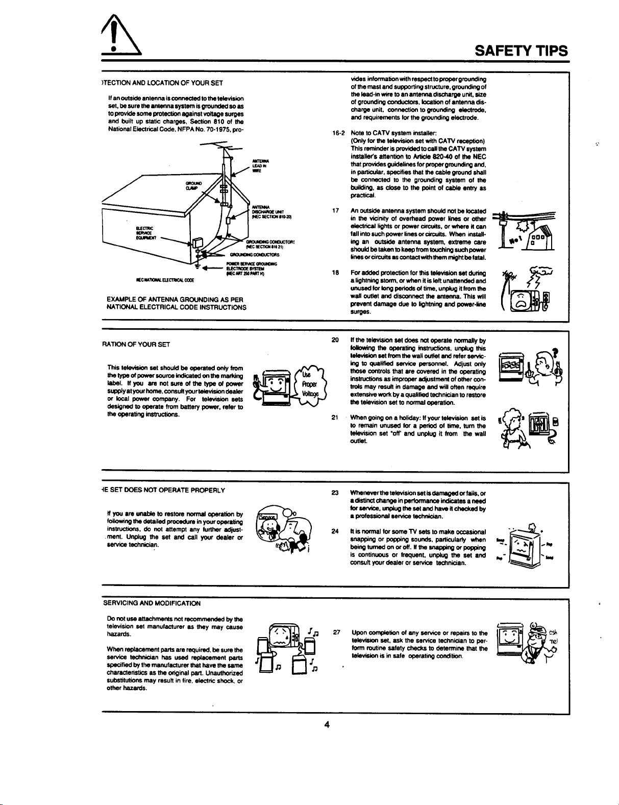
)TECTION AND LOCATION OF YOUR SET
Ifan outside antenna is connected to the television
set, be sum the amenna systam isgrounded sees
to provide some protection against voltage surges
and built up static charges, Section 810 of the
National Electrical Code, NFPA No. 70-1975, pro-
°
lee it_,11_ EUECl_ C_
EXAMPLE OF ANTENNA GROUNDING AS PER
NATIONAL ELECTRICAL CODE INSTRUCTIONS
RATION OF YOUR SET
This tele_slen set should be operated only from
the type of pewer seurce indldatad on the maddng
label. Ifyou am not sure of the type of power
supply at your home, consult your television dealer
or local power company. For television sets
designed to operate from battery power, refer to
the oporating instructions.
_K-€k_T2SaI_Kr N)
vides information with respect to proper grounding
of the mast and supporting structure, grounding of
the lead.in w_e to an antenna disctmrge unit, size
of grounding conductors, location of antenna dis-
charge unit, connection to grounding electrode,
and requirements for the grounding electrode.
16-2
Nots to CATV system installer:
(Only Itx the television set with CATV reception)
This reminder is providad to call the CATV system
installer's attention to Article 820-40 of the NEC
that provides guidelines for proper grounding and,
in parer, specifies that the cable ground shall
he connected to the grounding system of the
building, as c_ to the point of cable entnj as
practical.
17
An outside antenna system should not be located
in the vicinity of overhead power lines or other
electrical lights or power circuits, or where it can
fall into such power lines or c_,ouits. When install-
ing an outside antenna system, extreme care
should be taken to keep/TOm touching such power
lines or circuits as contact with them might be fatal.
18
For added protection for this television set during
a lightning storm, or when itis left unattended and
unosad Ior leng periods of tirne, unplug itfrom the
wall outlet and disconnect the antenna. This will
prevent damage due to lightning and power-line
surges.
20
If the takrAsion set does not operate normally by
Ioitowing the operating instructions, unplug this
tal_ set from the waft ouitel and refer servic-
ing to qualmed senaco personnel. Adjust only
those controls that are covered in the operating
instructions as improper adjustment of other con-
trois may result in damage and will often require
extensive work by a qualified technician to restore
the television set to normal operation.
21
When going on a holiday: If your television set is
to remain unused for a period of lime, lum the
talevision set "off' and unplug it from the wall
outlet.
-IE SET DOES NOT OPERATE PROPERLY
If you are Unable to restore normal operation by
following the detailed procedure in your operating
instructions, do not attempt any further adjust-
ment. Unplug the set and call your pealer or
sen.ice technician.
SERVICING AND MODIFICATION
Do not use att_hmants not recommended by the
television set manufacturer as they may cause
hazards.
When replacement parts are required, be sure the
service technician has used replacement paris
specified by the manufacturer that have the same
characteristics as the original part, Unauthorized
substitutions may result in fire, electric shock, or
other hazards.
23
Whenaverthe talevisionset isdamagedor falls,or
a distinotchangeinperfon'nanoe indicatasa noed
forservice,unplugtheset end havoit checkedby
a p_ossional service technician.
24
It is normal for some TV sets to make occasional
snapping or Popping sounds, particularly when
being turned on or off. ti the seapplng or popping
is continuous or frequent, unplug the set and
consult your dealer or service technician.
27
Upon completion of any sennce or repairs to the
talevismn set, ask the service techn_an to per-
form routine safety checks to determine that the
televismn is in safe operating condition,
4
csk
Page 5
PICTURE CAUTIONS
Continuous on-screen displays such as
video games, stock market quotations,
computer generated graphics, and other
fixed (non-moving) patterns can cause per-
WARNING
manent damage to color television receiv-
ers. Such "PATTERN BURNS" constitute
misuse and are NOT COVERED by your
Hitachi Factory Warranty.
When using the Picture-in-Picture function, the sub-picture should not be left permanently
in one corner of the screen or a "pattern burn" may develop over a long period of time.
This Color television receiver was intended mainly for the private viewing of programs
broadcast by TV stations and cable companies and programs from other video sources.
Public viewing may require prior authorization from the broadcaster or owner of the video
program.
Page 6
ACCESSORIES
:k to makesureyou havethefollowingaccessoriesbeforedisposingofthe packingmaterial.
nformationregardinghowto obtaintheseaccessories,please callTOLL FREE 1-800-448-2244 for yournearest
_CHIAuthorizedPartsDistributorinthecontinentalUnitedStates. ForAlaskaandHawaii,pleasecontactyounearest
\CHI Regionaloffice
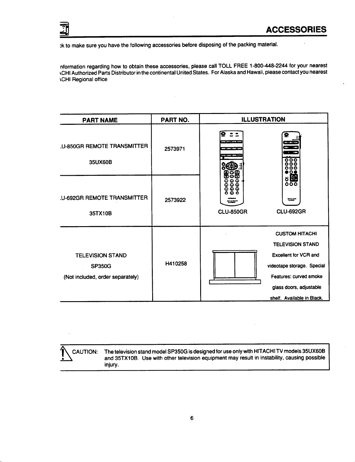
PART NAME PART NO. ILLUSTRATION
.U-850GR REMOTE TRANSMITTER
35UX60B
.U-692GR REMOTE TRANSMITTER
35TX10B
TELEVISION STAND
SP350G
(Notincluded,orderseparately)
2573971
2573922
H410258
CLU-850GR
Z
OOO
OOO
OOO
IIJIB
I
CLU-692GR
CUSTOM HITACHI
TELEVISION STAND
Excellent for VCR and
videotape storage. Special
Features: curved smoke
"7
glass doors, adjustable
shelf. Available in Black.
._CAUTION: ThetelevisionstandmodelSP350G isdesignedforuseonlywithHITACHI TVmodels35UX60B
and 35TX10B. Use withother televisionequipmentmayresultin instability,causingpossible
injury.
6
Page 7
REMOTE CONTROL BATTERY INSTALLATION AND
REPLACEMENT
1=
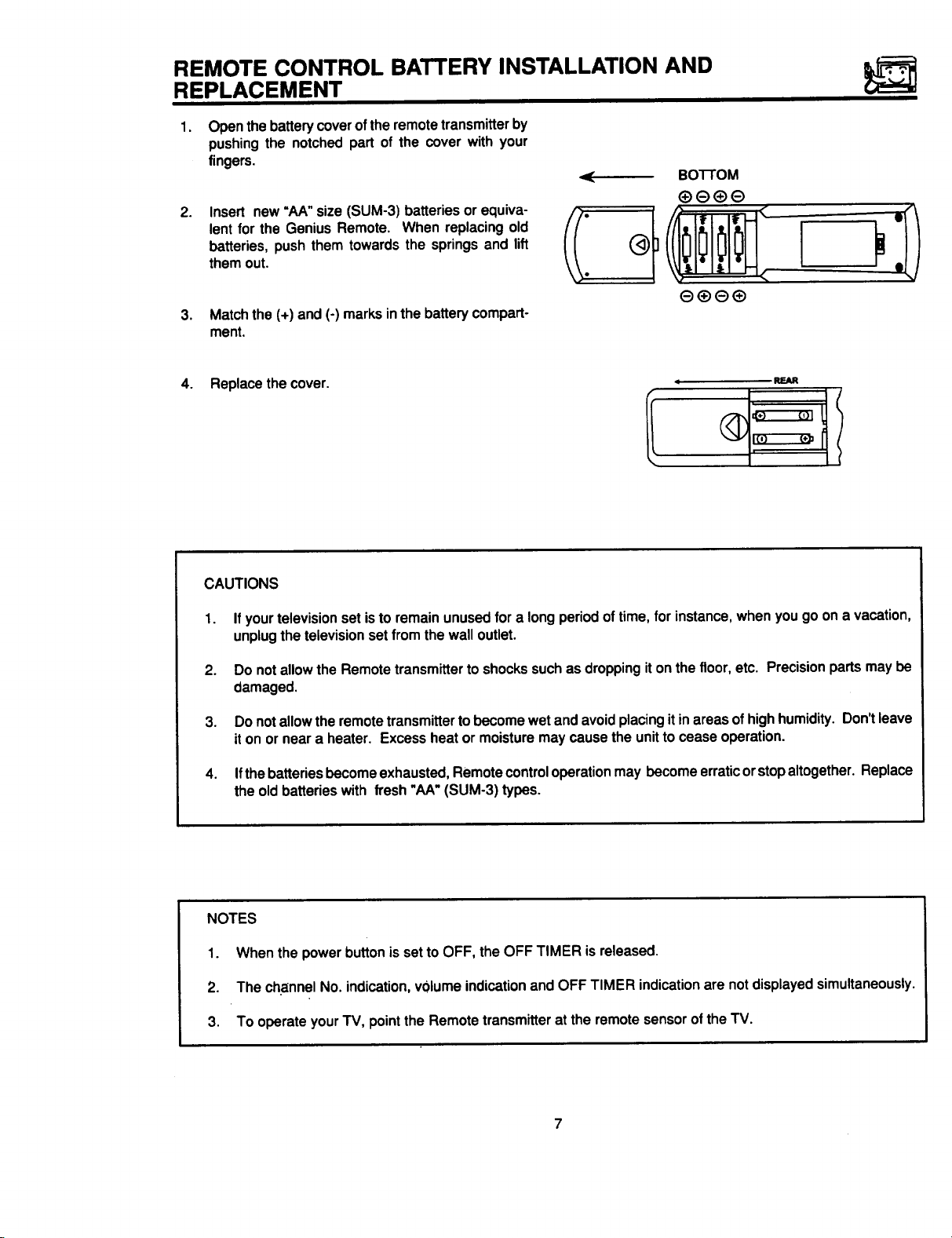
Open the battery cover of the remote transmitter by
pushing the notched part of the cover with your
fingers.
.
Insert new"AA"size(SUM-3) batteriesorequiva-
lent forthe Genius Remote. When replacingold
batteries, pushthem towardsthe springsand lift
themout.
.
Matchthe (+)and (-) marksinthe batterycompart-
ment.
4. Replacethe cover.
BoI-rOM
I
CAUTIONS
1. Ifyourtelevisionset isto remainunusedfor a longperiod oftime, for instance,whenyougo ona vacation,
unplugthe televisionset from the walloutlet.
2. Do notallowthe Remotetransmittertoshockssuchasdroppingit onthe floor,etc. Precisionparts maybe
damaged.
3. Do notallowtheremote transmittertobecomewet andavoidplacingitinareasofhighhumidity.Don'tleave
iton orneara heater. Excessheat ormoisturemay cause theunittocease operation.
4. Ifthebatteriesbecomeexhausted,Remotecontroloperationmay becomeerraticorstopaltogether.Replace
the oldbatterieswith fresh"hA"(SUM-3) types.
NOTES
1. When thepower buttonissetto OFF, the OFF TIMER isreleased.
2. The channelNo. ndcat on,volumeindicationand OFF TIMER indicationare notdisplayedsimultaneously.
3. To operateyourTV, pointthe Remotetransmitteratthe remotesensoroftheTV.
Page 8
HOW TO SET UP YOUR NEW HITACHI COLOR TV
ENNA
_syour TV isconnected to a cable TV system or to a centralized antenna system, a good outdoor colorTV antenna
•ommended for the best performance. However, ifyou are located in an exceptionally good signal area that is free
interference and multiple image ghosts, an indoor antenna may be sufficient.
ATION
:t an area where sunlight or bright indoor illumination will not fall directly on the picture screen. Also, be sure that
_cation selected allows a free flow of air to and from the perforated back cover of the set.
void cabinet warping, cabinet color changes, and increased chance of set failure, do not place the TV where
eratures can become excessively hot. For example, indirect sunlight or near a heating appliance, etc.
lING
"najor benefit of the HITACHI Color Television is its
viewing screen. To see this large screen at its best,
,arious locations in the room to find the best spot for
ng. The drawings give several suggestions.
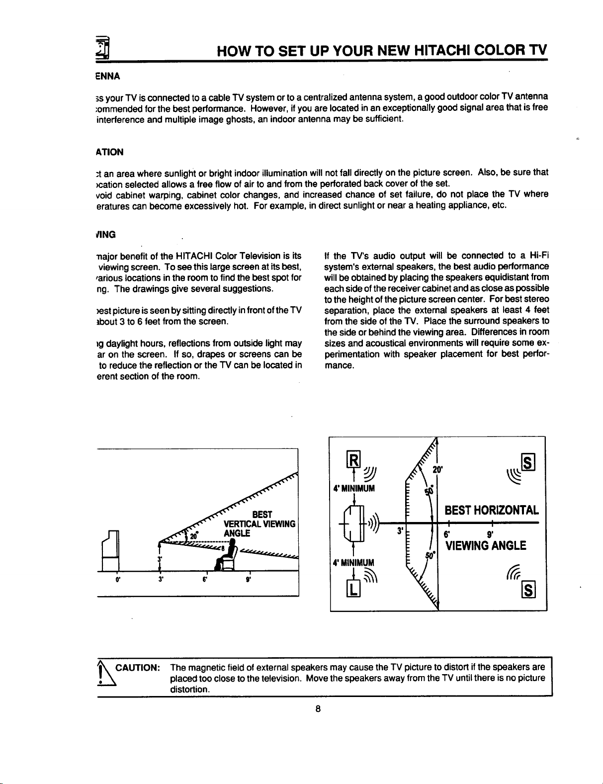
_estpictureisseen bysittingdirectlyinfrontoftheTV
tbout 3 to 6 feet from the screen.
_gdaylight hours, reflections from outside light may
ar on the screen. If so, drapes or screens can be
to reduce the reflection or the TV can be located in
erent section of the room.
BEST t
VER'IICALVIEWING|
ANGLE
If the TV's audio output will be connected to a Hi-Fi
system's external speakers, the best audio performance
will be obtained by placing the speakers equidistant from
each side ofthe receiver cabinet and as close as possible
to the height ofthe picture screen center. For best stereo
separation, place the extemal speakers at least 4 feet
from the side of the TV. Place the surround speakers to
the side or behind the viewing area. Differences in room
sizes and acoustical environments will require some ex-
perimentation with speaker placement for best perfor-
mance.
I B STHOR,EONT'L
4'MINI_MUM _ _°1 VIEWING ANGLE
'_CAUTION:
' 1
I
The magnetic field of external speakers may cause the TV picture to distort ifthe speakers are
placed too close to the television. Move the speakers away from the TV untilthere is no picture
Idistortion.
Page 9
HOOK-UP CABLES AND CONNECTORS
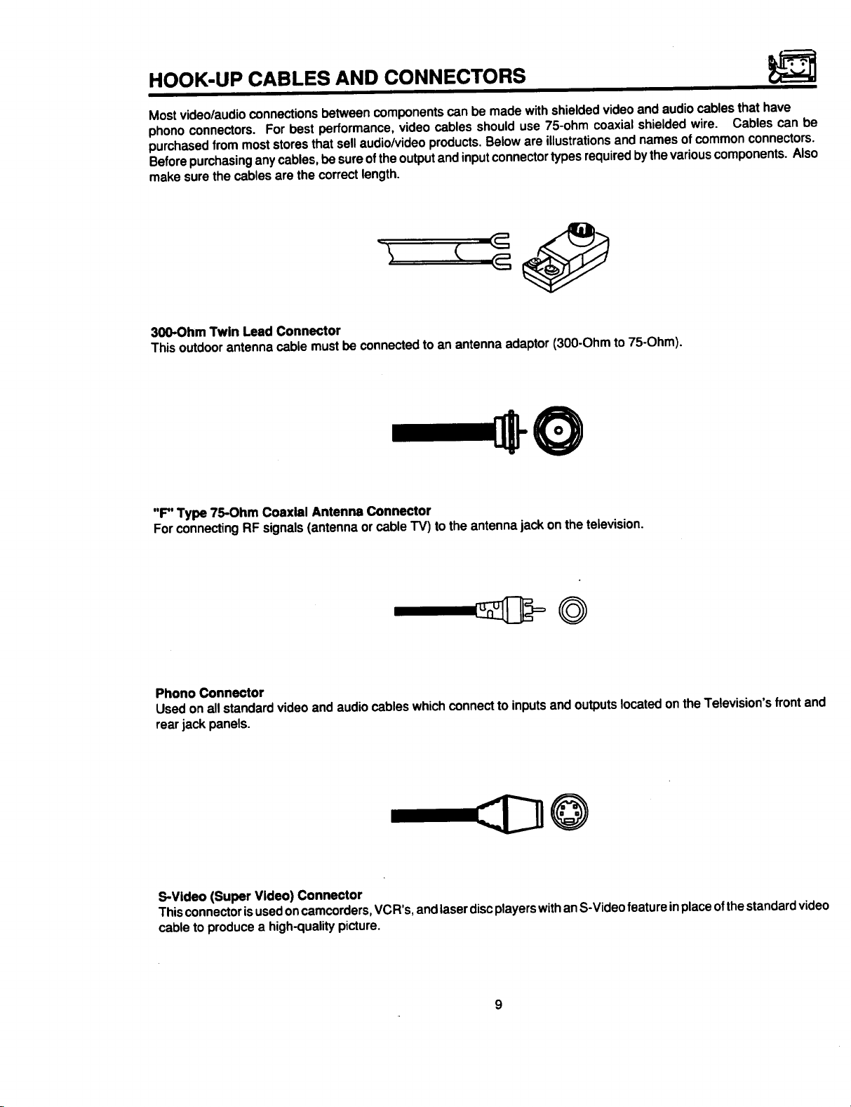
Most video/audio connections between components can be made with shielded video and audio cables that have
phono connectors. For best performance, video cables should use 75-ohm coaxial shielded wire. Cables can be
purchased from most stores that sell audio/video products. Below are illustrations and names of common connectors.
Before purchasing any cables, be sure of the output and input connector types required by the various components. Also
make sure the cables are the correct length.
300-Ohm Twin Lead Connector
Thisoutdoorantennacable mustbe connectedto an antennaadaptor(300-Ohmto75-Ohm),
"F" Type 75-Ohm Coaxial Antenna Connector
ForconnectingRF signals(antennaor cable TV) to the antennajack on thetelevision.
Phono Connector
Used onall standardvideoand audiocableswhichconnect toinputsand outputslocatedonthe Television'sfrontand
rearjack panels.
S-Video (Super Video) Connector
This connector isused on camcorders, VCR's, and laser disc players with anS-Video feature inplace of thestandard video
cable to produce a high-quality picture.
9
Page 10
HOOK-UP CABLES AND CONNECTORS
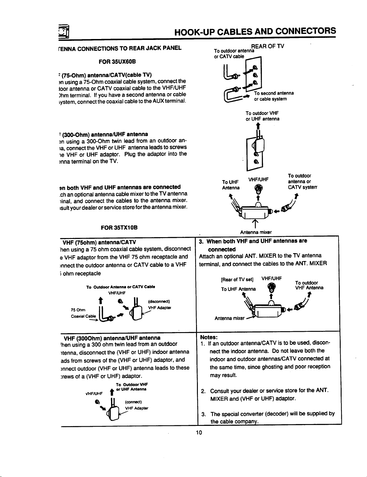
rENNA CONNECTIONS TO REAR JACK PANEL
FOR 35UX6OB
: (75-Ohm) antenna/CATV(cable TV)
.=nusing a 75-Ohm coaxial cable system, connect the
toor antenna or CATV coaxial cable to the VHF/UHF
)hm terminal. If you have a second antenna or cable
;ystem, connect the coaxial cable to the AUX terminal.
"(300-Ohm) antenna/UHF antenna
.=nusing a 300-Ohm twin lead from an outdoor an-
la, connect the VHF or UHF antenna leads to screws
le VHF or UHF adaptor. Plug the adaptor into the
)nna terminal on the TV.
.=nboth VHF end UHF antennas are connected
;chan optional antenna cable mixer to theTV antenna
linal, and connect the cables to the antenna mixer.
=suityourdealer or service storeforthe antenna mixer.
Tooutdoorantenna
REAR OF TV
TooutdoorVHF
orUHFantenna
t
ToUHF VHF/UHF antennaor
Antenna O CATV systerr
Tooutdoor
FOR 35TX10B
VHF (75ohm) antenna/CATv
'hen using a 75 ohm coaxial cable system, disconnect
e VHF adaptor from the VHF 75 ohm receptacle and
)nnect the outdoor antenna or CATV cable to a VHF
ohm receptacle
To Outdoor Antenna or CAW Cable
VHF/UHF
t = U ("==)
II
VHF (300Ohm) antenna/UHF antenna
Phenusing a 300 ohm twin lead from an outdoor
ltenna, disconnect the (VHF or UHF) indoor antenna
ads from screws of the (VHF or UHF) adaptor, and
)nnect outdoor (VHF or UHF) antenna leads to these
"rews of a (VHF or UHF) adaptor.
To Outdoor VHF
VHFIUHF t or UHF Antenna
Q' I,I (contact)
Antennamixer
3. When both VHF and UHFantennas are
connected
Attachan optionalANT. MIXER to the TV antenna
terminal,and connectthecablestotheANT. MIXER
[RearofTVset] VHF/UHF
ToUHFAntenna VHF Antenna
_) To outdoor
t t
Antennamixe;_ _ 4" _/
Notes:
1. If an outdoorantenna/CAW is tobe used,discon-
nect the indoor antenna. Do not leave both the
indoor and outdoor antennas/CATv connected at
the same time, since ghosting and poor reception
may result.
.
Consultyourdealeror servicestorefortheANT.
MIXER and (VHFor UHF) adaptor.
_IL(_HF Adapter
.
The special converter (decoder) will be supplied by
the cable company.
10
Page 11
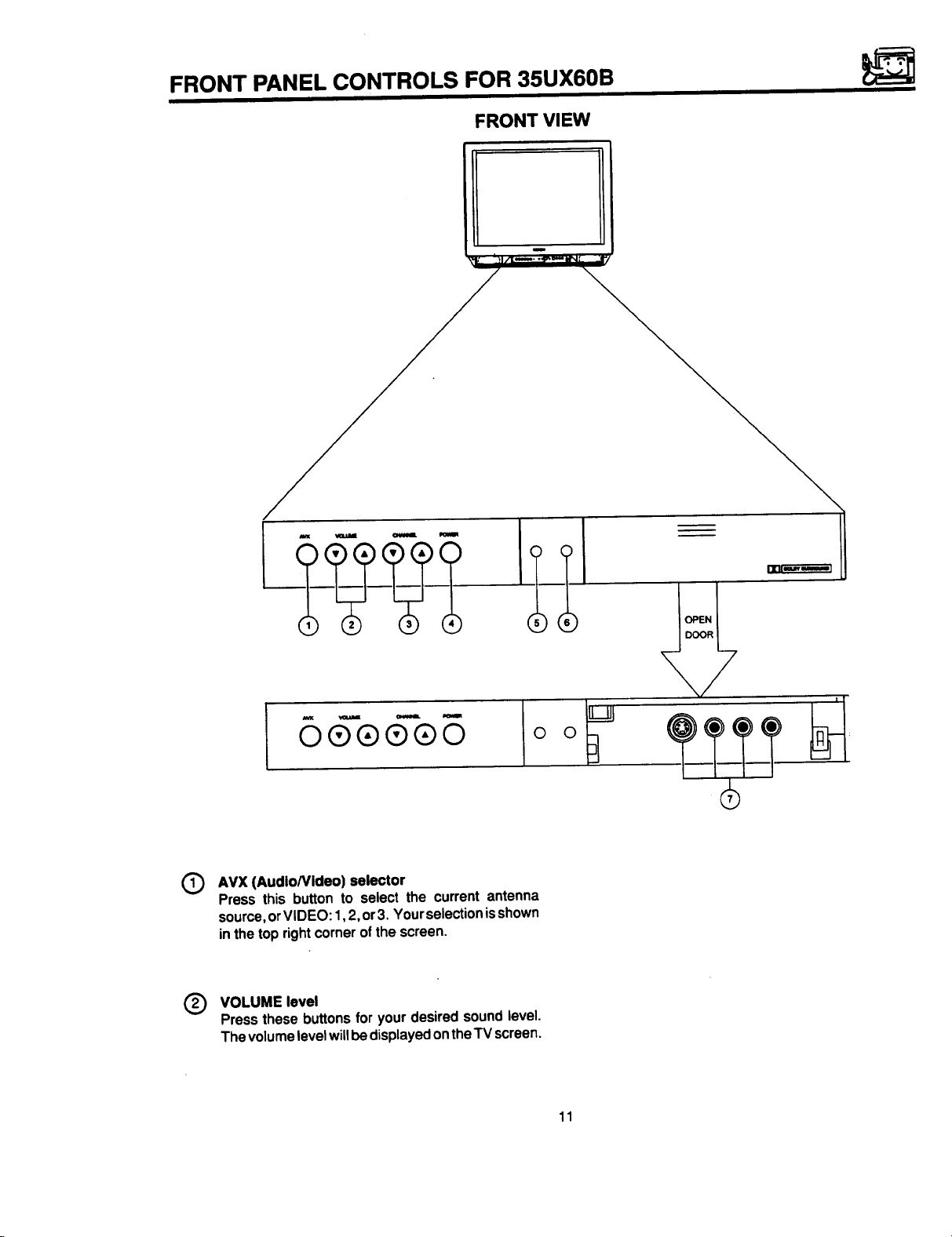
FRONT PANEL CONTROLS FOR 35UX60B
FRONT VIEW
6 €-®5
AVX (AudloNldeo) selector
®
Press this button to select the current antenna
source, or VIDEO: 1,2, or 3. Your selection isshown
in the top right corner of the screen.
Q VOLUME level
Pressthese buttonsfor yourdesiredsoundlevel.
ThevolumelevelwillbedisplayedontheTV screen.
11
Page 12
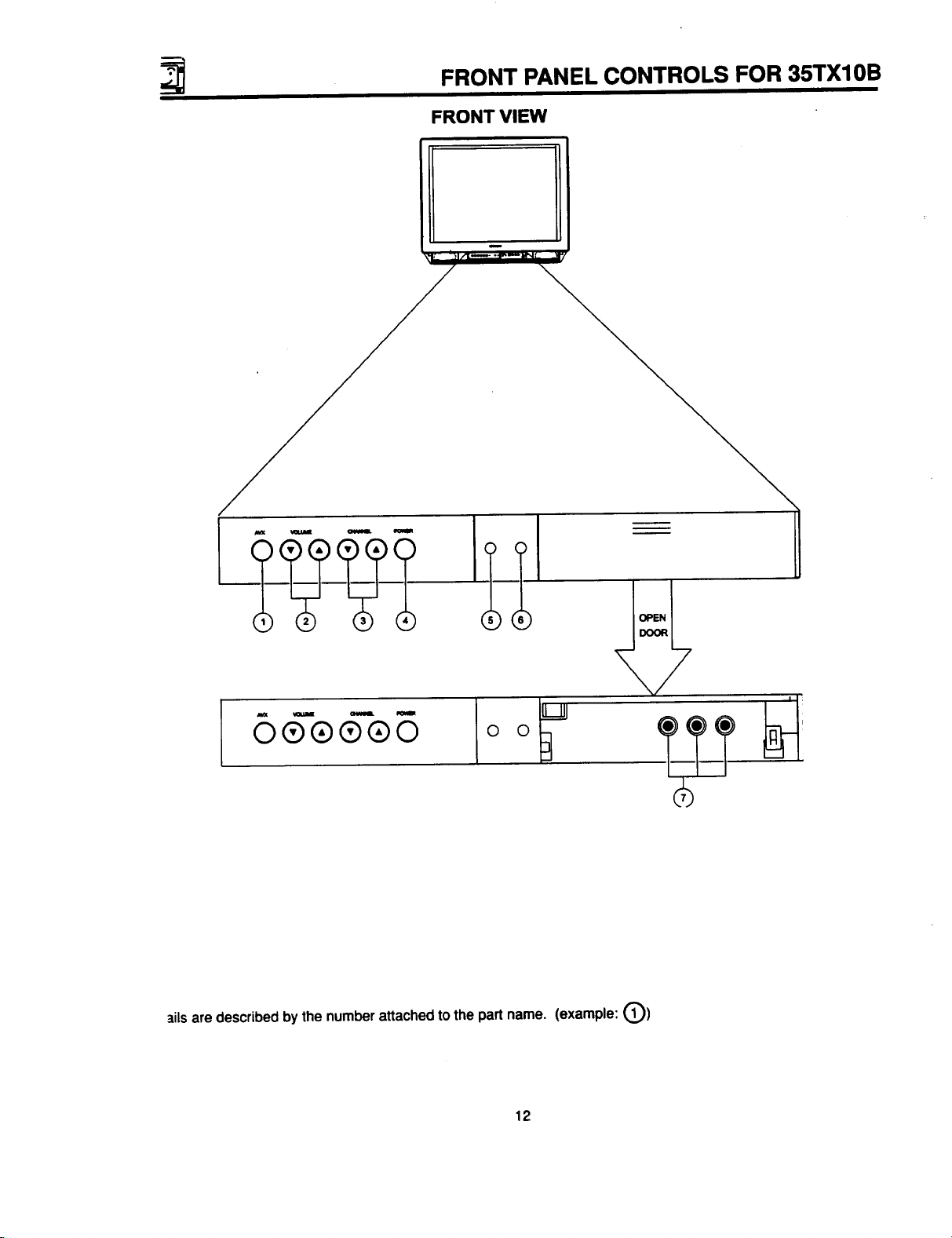
FRONT PANEL CONTROLS FOR 35TX10B
FRONT VIEW
Ill . .Im
6 e-e_®_ o o
_ilsare describedby thenumberattachedto thepart name. (example:@)
12
Page 13
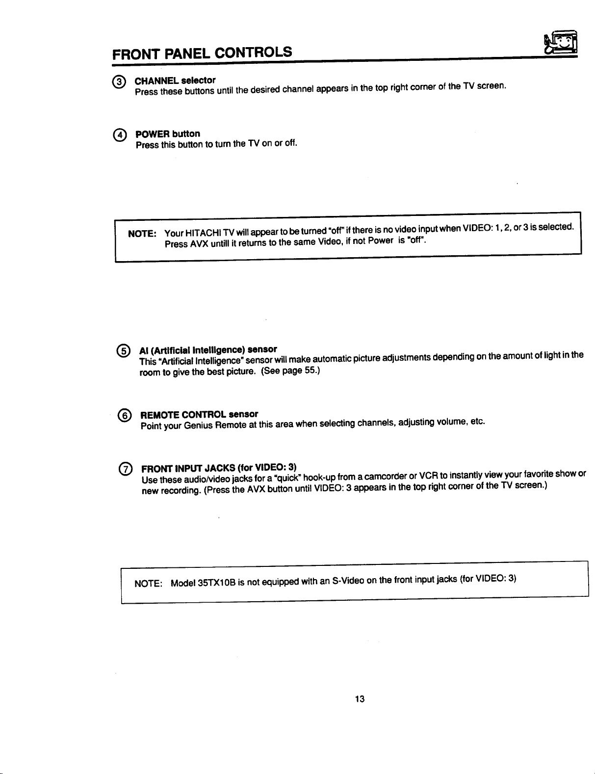
FRONT PANEL CONTROLS
(_) CHANNEL selector
Pressthesebuttonsuntilthe desiredchannelappearsinthe toprightcornerofthe TV screen.
(_ POWER button
Press thisbutton to turntheTV on oroff.
NOTE: YourHITACHITV willappearto beturned=off"ifthereis novideoinputwhenVIDEO: 1,2, or3 is selected.
PressAVX untillitreturnsto thesame Video,if notPower is"off".
(_) AI (Artificial Intelligence) sensor
This"ArtificialIntelligence_sensorwillmakeautomaticpictureadjustmentsdependingontheamountoflightinth_
roomto givethebest picture. (See page 55.)
(_ REMOTE CONTROL sensor
Pointyour GeniusRemoteatthisarea whenselectingchannels,adjustingvolume,etc.
(_) FRONT INPUT JACKS (for VIDEO: 3)
Usetheseaudio/videojacks fora =quick"hook-upfromacamcorderorVCR toinstantlyviewyourfavoriteshow¢
newrecording.(Pressthe AVX buttonuntilVIDEO:3 appears inthe toprightcornerofthe TV screen.)
I NOTE: Model35TX10B isnot equippedwithan S-Videoonthe frontinputjacks (forVIDEO: 3)
13
Page 14
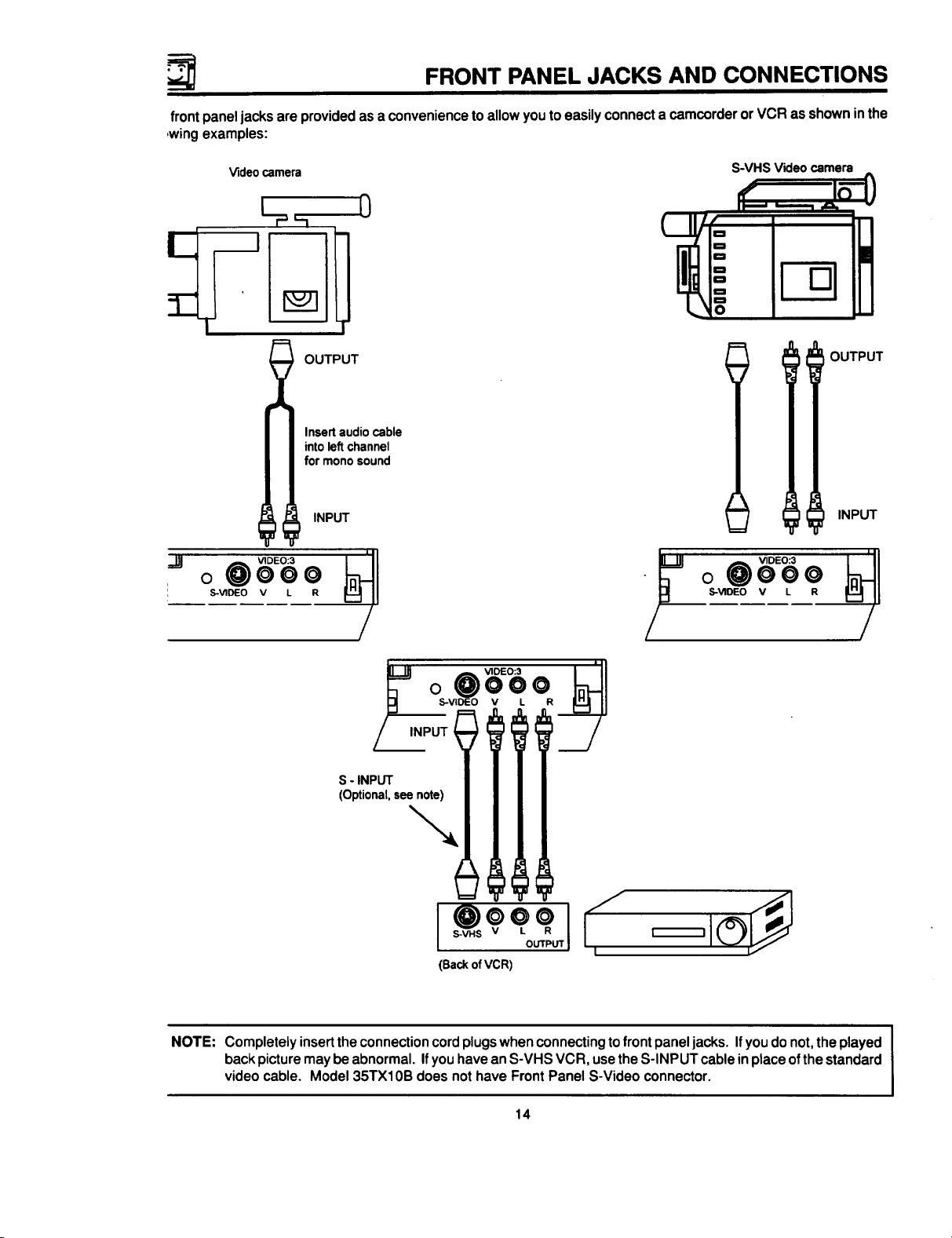
FRONT PANEL JACKS AND CONNECTIONS
front paneljacksare providedas aconveniencetoallowyouto easilyconnecta camcorderorVCR asshowninthe
,wing examples:
V_deocamera
i OUTPUT
for mono sound
.,_ VIDEO:3
o 0ooo
I S-V1DEO v L R
Insert audio cable
into leftchannel
INPUT
S-VHS Video camera
_=
o
f
OUTPUT
INPUT
INPUT ? I I I
NOTE: Completelyinsertthe connectioncordplugswhenconnectingtofront paneljacks. Ifyoudo not,theplayed
backpicturemaybe abnormal.If youhaveanS-VHS VCR, usetheS-INPUTcableinplaceofthe standard
videocable. Model 35TX10B does nothave FrontPanelS-Video connector.
14
Page 15
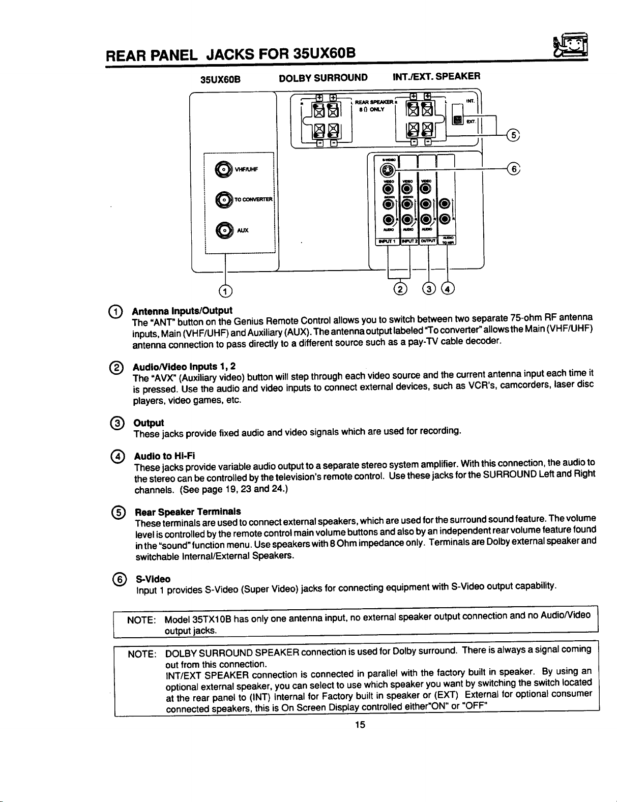
REAR PANEL JACKS FOR 35UX60B
35UX60B DOLBY SURROUND INTJEXT. SPEAKER
i
®
i
'O
i TO CONVERTER
!
i
@
Antenna Inputs/Output
The "ANT" button on the Genius Remote Control allows you to switch between two separate 75-ohm RF antenna
inputs, Main (VH F/UHF) and Auxiliary (AUX). The antenna output labeled "To converter" allowsthe Main (VH F/UHF)
antenna connection to pass directly to a different source such as a pay-TV cable decoder.
AudioNideo Inputs 1, 2
®
The "AVX" (Auxiliary video) button will step through each video source and the current antenna input each time it
is pressed. Use the audio and video inputs to connect external devices, such as VCR's, camcorders, laser disc
players, video games, etc.
®
Output
These jacksprovidefixedaudioandvideosignalswhichare usedforrecording.
Audio to HI-Fi
®
These jacks provide variable audio output to a separate stereo system amplifier. With this connection, the audio to
the stereo can be controlled by the television's remote control. Use these jacks forthe SURROUND Left and Right
channels. (See page 19, 23 and 24.)
®
Rear Speaker Terminals
Theseterminalsareusedtoconnectexternalspeakers,whichareusedfor thesurroundsoundfeature.The volume
leveliscontrolled bytheremotecontrolmainvolumebuttonsandalsobyanindependentrearvolumefeaturefound
inthe=sound"functionmenu.Use speakerswith8Ohm impedanceonly.TerminalsareDolbyexternalspeakerand
switchableInternal/ExternalSpeakers.
S-Video
Input1providesS-Video (SuperVideo) jacksforconnectingequipmentwithS-Videooutputcapability.
NOTE:
NOTE:
Model 35TX10B has only one antenna input, no external speaker output connection and no AudioNideo I
output jacks. I
DOLBY SURROUND SPEAKER connection is used for Dolby surround. There is always a signal coming
out from this connection.
INT/EXT SPEAKER connection is connected in parallel with the factory built in speaker. By using an
optional external speaker, you can select to use which speaker you want by switching the switch located
at the rear panel to (INT) Internal for Factory built in speaker or (EXT) External for optional consumer
connected speakers, this is On Screen Display controlled either"ON" or "OFF"
15
!
Page 16
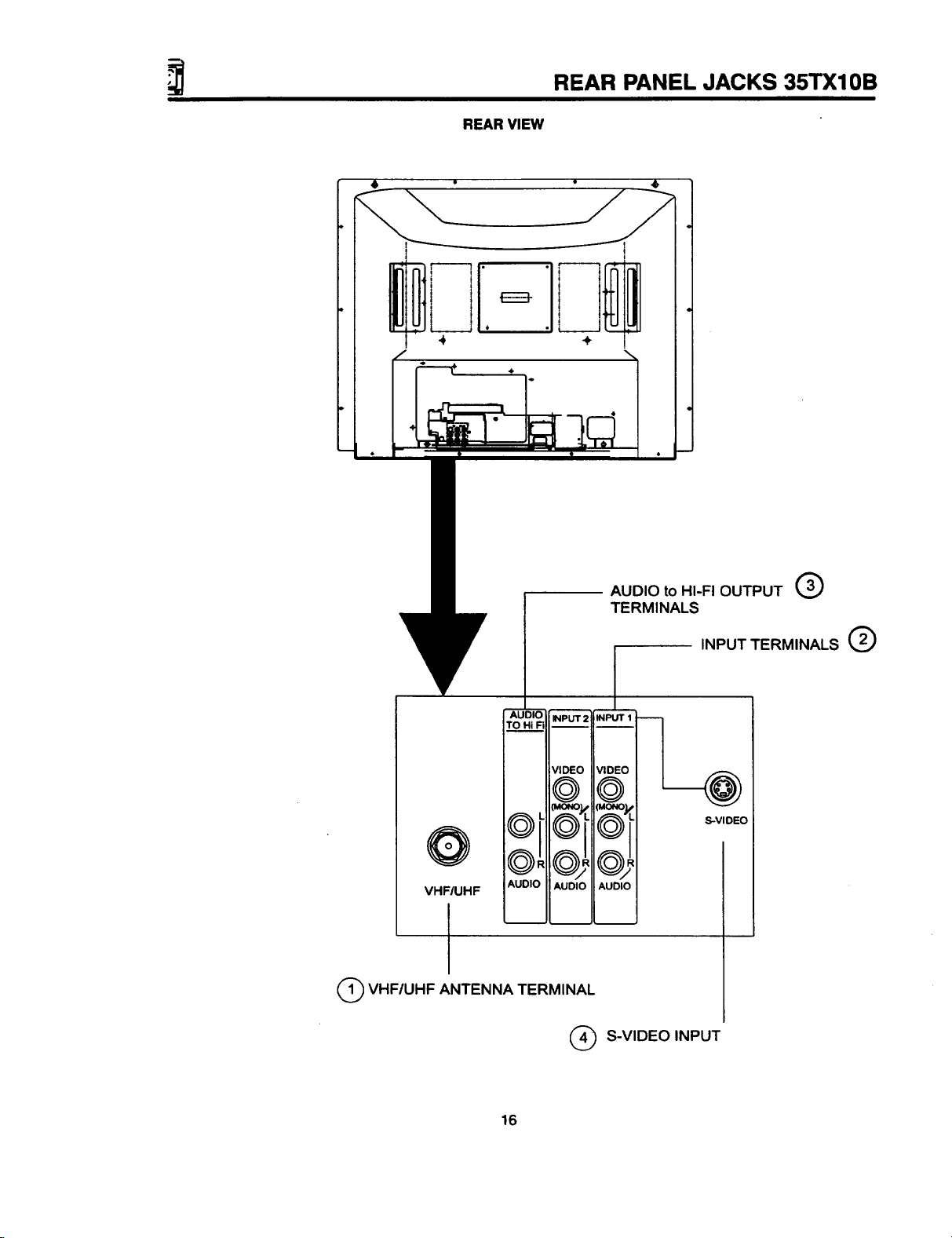
REAR VIEW
REAR PANEL JACKS 35TX10B
÷
AUDIO
INPUT 2
TO Hi I=i
VIDEO
©
L
o!
d,
AUDIO
VHFIUHF
AUDIO
I
Q VHF/UHF ANTENNA TERMINAL
(_) S-VIDEO INPUT
AUDIO to HI-FI OUTPUT _/
TERMINALS
INPUT TERMINALS Q
INPUT 1 l_
VIDEO
©
S-VIDEO
oJ,
AUDIO
16
Page 17
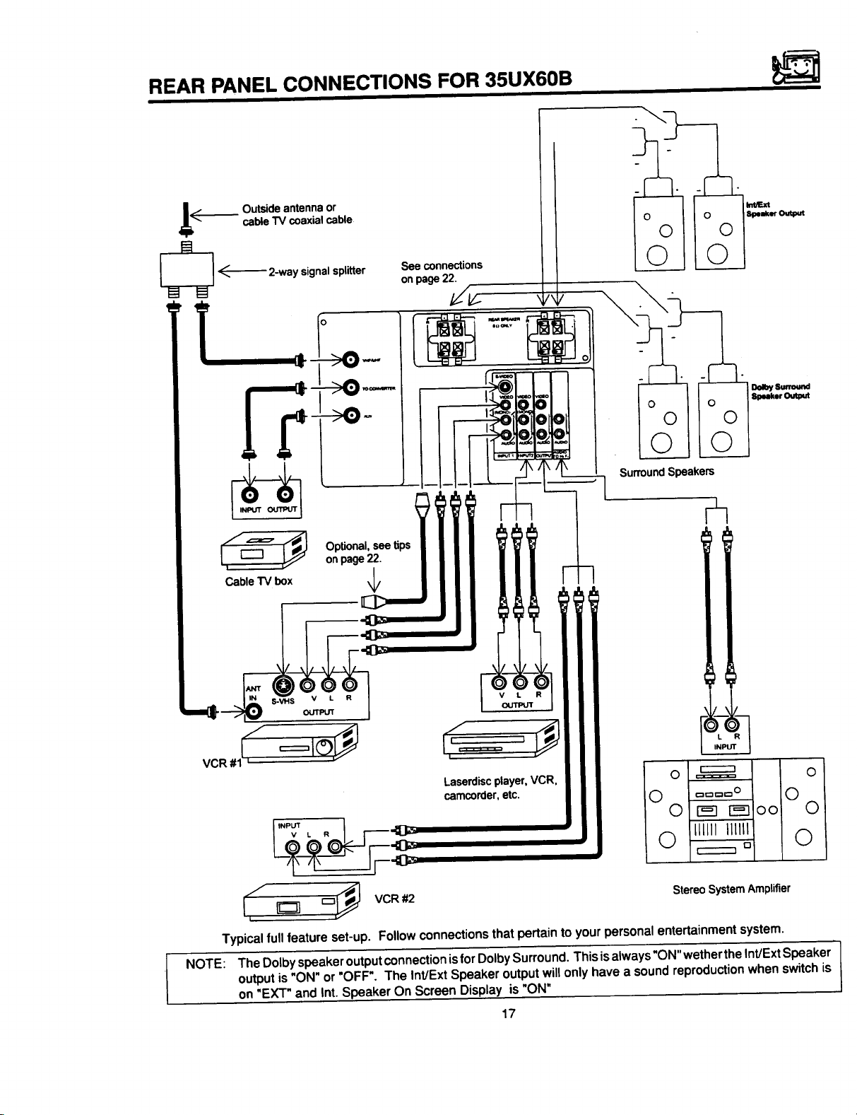
REAR PANEL CONNECTIONS FOR 35UX60B
_ii_ Outside antenna or
E
_ _---'--'-2-way signal splitter
cable TV coaxial cable
1----I _J Optional,see tips
t
Cable"IV box ,I,
onpage22.
See connections
onpage22.
Surround Speakers
/
_V
Laserdiscplayer,VCR,
camcorder,etc.
O =====:= O
O
c=_c="O O
0 I_ r_-]oo 0
i"Pv_ , . I r----<l_
0 111111IIIIII 0
r-----'n
Stereo System Amplifier
_ VCR #2i
Typicalfullfeature set-up. Followconnectionsthatpertaintoyour personalentertainmentsystem.
NOTE: The Dolby speaker output connection isfor Dolby Surround. This is always"ON" wether the Int/Ext Speaker
output is "ON" or "OFF". The Int/Ext Speaker output will only have a sound reproduction when switch is
on "EXT" and Int. Speaker On Screen Display is "ON"
17
D
Page 18
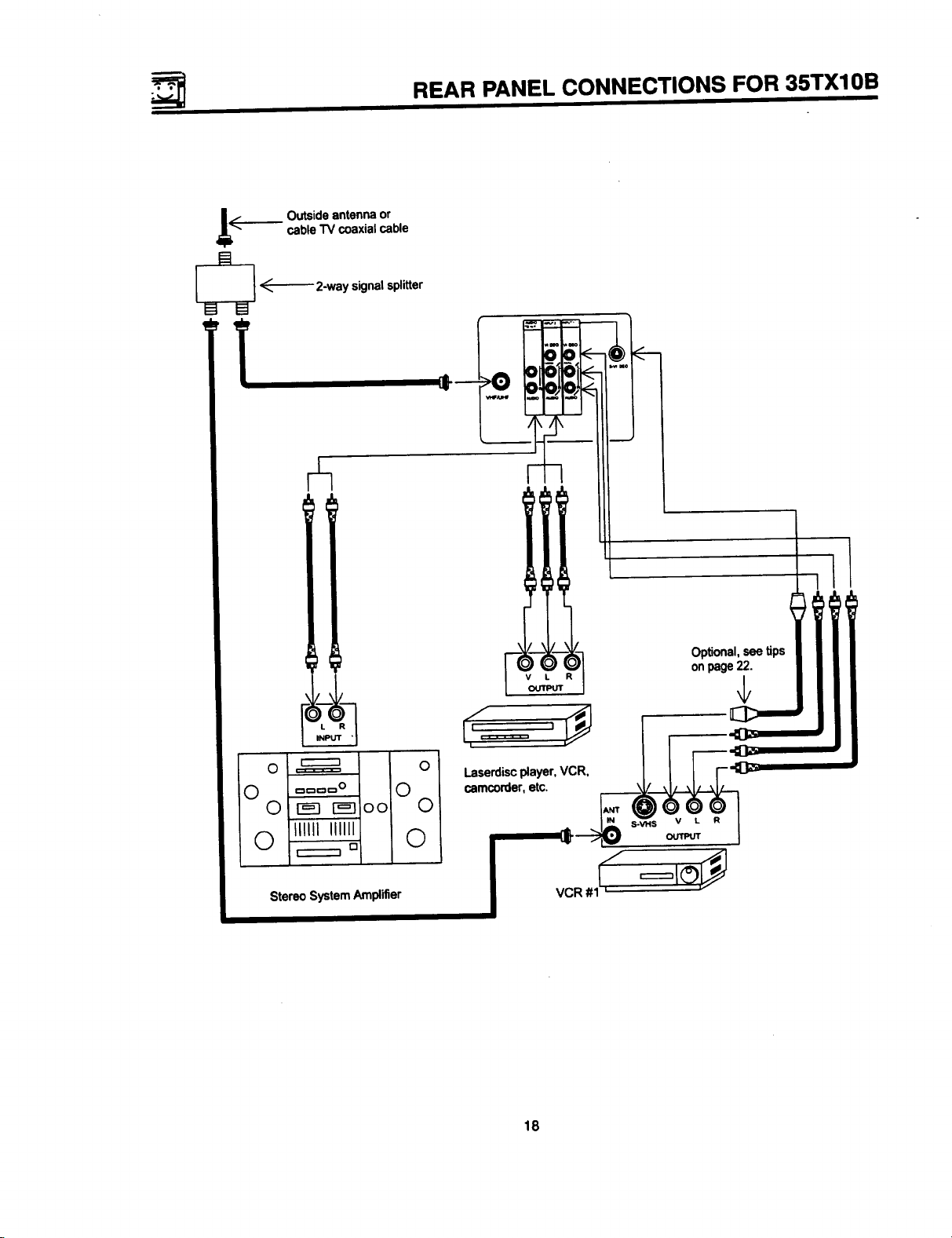
REAR PANEL CONNECTIONS FOR 35TX10B
_L_ Outside antenna or
_ _'----2-way signal splitter
cable TV coaxial cable
iI
Stereo System Amplifier
= II
18
Page 19
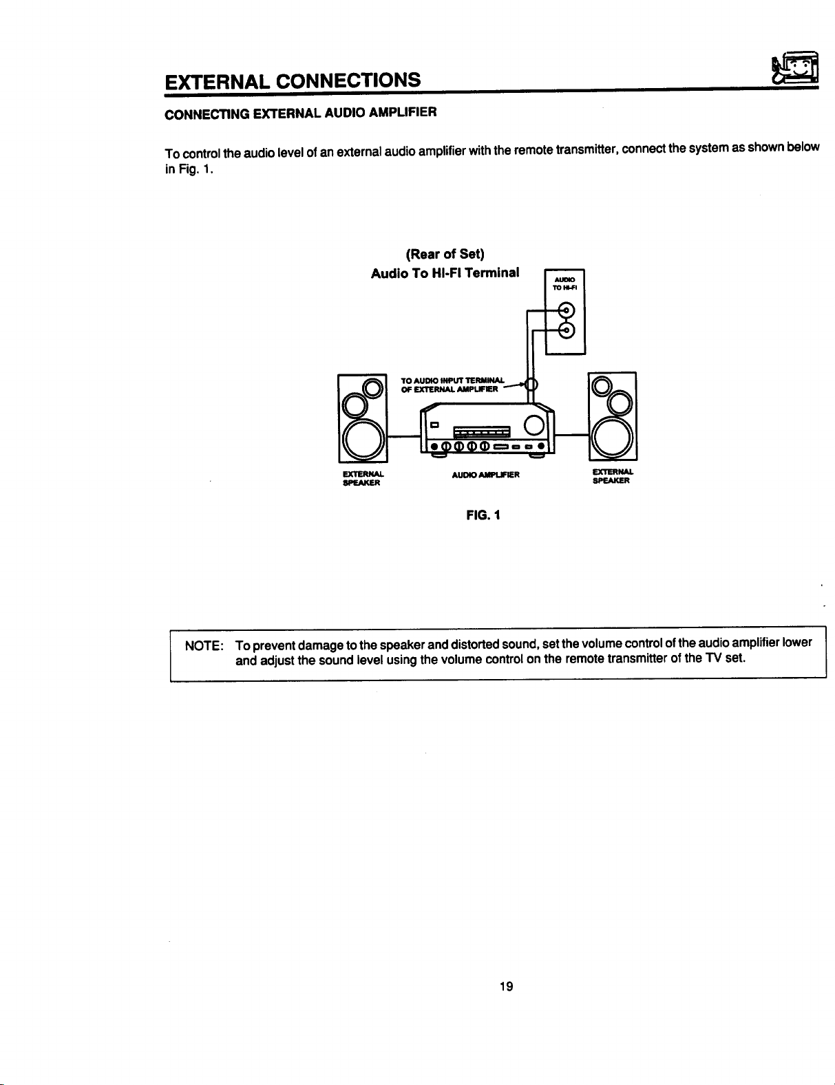
EXTERNAL CONNECTIONS
CONNECTING EXTERNAL AUDIO AMPLIFIER
To control the audio level of an external audio amplifier with the remote transmitter, connect the system as shown below
in Fig. 1.
(Rear of Set)
Audio To HI-FI Terminal
TO AUDIO INPUT TERMUqAL
OF EXTERNAL AMPlJ:IER
EXTERNAL AUDIO _ EXTERNAL
SPEAKER SPEAKER
FIG. 1
NOTE: To prevent damage to the speaker and distorted sound, set the volume control ofthe audio amplifier lower
and adjust the sound level using the volume control on the remote transmitter of the TV set.
19
Page 20
CONNECTING EXTERNAL VIDEO SOURCES
e exact arrangement you use to connect the Video Cassette Recorder, Video Disc Player and Video camera to your
set isdependent on the model and features of each component. Check the Owner's Manual of each component for
; location of its video and audio inputs and outputs. The following connection diagrams are offered as suggestions.
wever, youmay need to modify them toaccommodate you particular assortment of components and features. For best
.'formance, video and audio cables should be made from coaxial shielded wire.
fore Operating External Video Source
einput mode is changed every time the AVX button is pressed as shown below. Connect External source tothe INPUT
rninal, then press the AVX button as necessary to view the input source.
INPUT MODE SELECTION ORDER
NOTE: When TV isset to "VIDEO" and a video signal is not received from VIDEO INPUT JACK on thejack panel
of the TV (i.e., VCR/Video Disc Player, etc. is not connected or the video device is OFF), the screen will
be black.
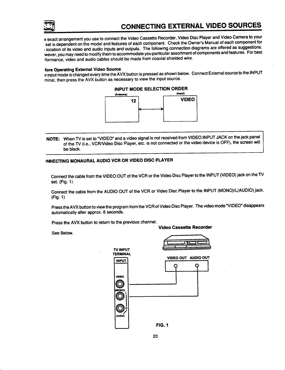
)NNECTING MONAURAL AUDIO VCR OR VIDEO DISC PLAYER
Connectthecablefrom theVIDEO OUT ofthe VCRortheVideo Disc Playertothe INPUT(VIDEO) jackon theTV
set. (Fig. 1)
Connect the cable from the AUDIO OUT of the VCR or Video Disc Player to the INPUT (MONO)/L(AUDIO) jack.
(Fig. 1)
PresstheAVXbuttontoviewtheprogramfromtheVCR ofVideoDiscPlayer. Thevideomode"VIDEO"disappears
automaticallyafter approx. 8 seconds.
Pressthe AVX buttonto returnto thepreviouschannel.
Video Cassette Recorder
See Below,
TV INPUT
TERMINAL
INPUT
• t, '%1_
VIDEOOUT AUDIO OUT
I
VIOEO
MONO_
AUDIO
FIG. 1
2O
Page 21

CONNECTING EXTERNAL VIDEO SOURCES
CONNECTING STEREO VCR OR STEREO VIDEO DISC PLAYER
1.
Connectthecablefrom theVIDEO OUT of theVCR ortheVideoDisc Playerto the"INPUT (VIDEO)" jackonthe
TV set.(Fig. 1)
Connectthecablefrom the AUDIOOUT "R" ofthe VCR ofthe VideoDiscPlayertothe "INPUT(AUDIO)R)" jack.
2.
(Fig. 1)
Connectthecable from theAUDIO OUT "L"of the VCR ofthe VideoDiscPlayerto the"INPUT(AUDIO/L)" jack.
.
(Fig. 1)
4.
PresstheAVXbuttontoviewtheprogramfromtheVCRorVideoDiscPlayer. Thevideomode"VIDEO"disappears
automaticallyafter approx.8 seconds.
5. Pressthe AVX buttonto returntothepreviouschannel. Video Cassette Recorder
T'V INPUT
TERMINAL
INPUT I
VIDEO I
AUDIO I
%
VIDEO OUT AUDIO OUT
L
I
FIG. 1
°°
NOTE:
=S-VHS V L R
o®®® I,
: HITACHI MODEL VT-S751A
BACK OF VCR
playedC°mpletelYbackinsertpicturethemayCOnnectiOnbeabnormal.C°rdplugs when connecting to REAR panel jacks. Ifyou do not the 1
Ifyouhave an S-VHS VCR, usethe S INPUT cable inplaceofthe standardvideo cable.
or =lmMormod_
21
Page 22
REAR SPEAKER TERMINAL CONNECTIONS FOR 35UX60B
ii I i i
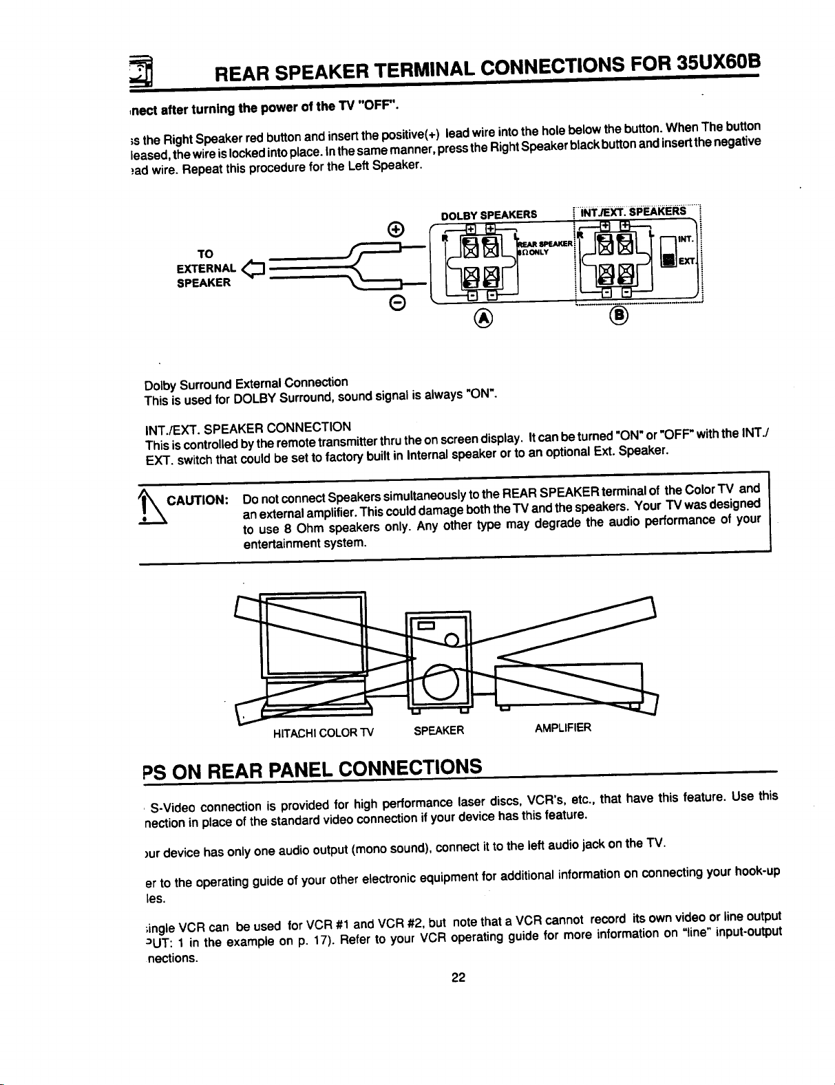
,nect after turning the power of the TV "OFF".
;s theRightSpeakerredbuttonandinsertthepositive(+)leadwireintothe holebelowthebutton.WhenThebutton
leased,thewireislockedintoplace.Inthesamemanner,pressthe RightSpeakerblackbuttonandinsertthenegative
}ad wire.Repeatthisprocedurefor the LeftSpeaker.
DOLBY SPEAKERS [ iNT__. si=_i(i_RS .......
TO
EXTERNAL <_]
SPEAKER
® ®
DolbySurroundExternalConnection
This isusedfor DOLBYSurround,soundsignalis always"ON'.
INT./EXT. SPEAKER CONNECTION
This is controlledby theremote transmitter thrutheon screendisplay.Itcan beturned "ON" or"OFF"withthe INT./
EXT. switchthat couldbe setto factory builtinInternalspeakerorto an optionalExt. Speaker.
o/_CAUTION:
Donotconnect Speakerssimultaneouslytothe REARSPEAKERterminalof theColorTV and
anexternalamplifier.Thiscoulddamagebeththe"IVandthespeakers. Your TV wasdesigned
to use 8 Ohm speakersonly. Any othertype may degrade the audio performance of your
entertainmentsystem.
C
HITACHICOLORTV SPEAKER AMPLIFIER
PS ON REAR PANEL CONNECTIONS
S-Video connection is provided for high performance laser discs, VCR's, etc., that have this feature. Use this
nection in place of the standard video connection if your device has this feature.
)ur device has only one audio output (mono sound), connect it to the left audio jack on the TV.
er to the operating guide of your other electronic equipment for additional information on connecting your hook-up
les.
;ingleVCR can be used for VCR #1 andVCR #2, but notethata VCR cannot record itsownvideoorlineoutput
JUT: 1 in the example on p. 17). Refer to your VCR operatingguide for more informationon "line" input-output
nections.
22
Page 23

LPr'r'r'r'r'r'r'r'r -
AUDIO SYSTEM SET-UP FOR 35UX60B
Matchthe numbersbelow to thediagramfor speakerplacementandrefertothe tableforthe differentsurroundsound
requirements.(Seepage 62 forSURROUND functions,)
O The television'sinternalspeakers.
O These speakersare connectedto a separate audioamplifier.Use the "AudiotoHi-Fi"outputonthe TV.
(_ These speakersare connectedto theRear Speaker8 Ohm outputontheTV.
JL
•, * OUT IN
%, " _ " AMPLIFIER
LR
STEREO SYSTEM
SURROUND REQUIRED OPTIONAL EFFECT
FEATURE CONNECTION CONNECTION
OFF Q (_ O ReceiveMonoandStereo Sound.
HALL Q O (_) ConcertHallSound.
MATRIX (_ O O Feelingof beingat aStadium.
DOLBY Q O O Movie TheaterReproduction,SurroundChannel
addedtoleft andrightaudioamplifierspeakers.
23
Page 24

AUDIO SYSTEM SET-UP
tchthe numbersbelow to the diagramforspeakerplacementandrefer tothetableforthe differentsurroundsound
luirements. (See page 61 for SURROUND functions.)
) The television'sinternalspeakers.
) These speakersare connectedto a separateaudioamplifier.Usethe "AudiotoHi-Fi"outputon the TV.
FOR 35TXl 0B
II
,o°o°° ...... ooo°o ..... o°o°oo.o,°ooo,
s! ol
SURROUND REQUIRED OPTIONAL EFFECT
FEATURE CONNECTION CONNECTION
OFF
s,.U TE ® ®
MUSIC
MOVIE
(_ (_ Receive Monoand StereoSound.
At MonoInput,soundischangedmore loudly
At stereoInput, soundof musicis changedmore
loudly,SurroundChanneladdedtoleft andright
AudioAmplifierspeakers.
©®
MovieTheater Reproduction,SurroundChannel
addedtoleft andrightaudioamplifierspeakers.
24
Page 25

THE GENIUS REMOTE CONTROL (CLU-850GR)
InadditiontocontrollingallthefunctionsonyourHITACHI
ColorTV, thenewGeniusRemoteisdesignedtooperate
differenttypes of VCR's and different types of CATV
(CableTV) converterswith one touch. Basicoperation
keysare groupedtogether inone area. Allothercontrols
areseparatedfromthem andarranged in MULTI-PAGE
To operateyourTV, pointtheGenius Remoteat the remotesensoroftheTV.
To operateyourVCR, pointtheremote atthe remotesensorofthe VCR.
®
r
©
POWER READY LEARN
sections,witha displaythatcanbeswitchedtocover any
ofthe four pages.Functionsare arrangedand properly
categorizedintowindows,makingoperationsimplewhen
multiplefunctionsare tobe controlled.
@ READY Indicator light
Refer to Page 38.
(_ SEND/LEARN Indicator
Refer topage38.
LEARN/USE select switch
(Locatedonrear sideof remotecontrol)
I II II II
light
I _rr II II II_-c_!
..... .....................................
@
Hrr_Hl
GENIUS REMOTE
CLU-850GR
J
(_),@ LIGHT button
LEARN........ Entersthe Learningmode.
(Referto page38.)
USE............ Set for normaluse.
MULTI-PAGE select switch
This selects the button layout of the multi-page
section of the remote control.
MULTI-PAGE buttons
These buttons change functions as shown on
page 26.
When you are in a dark room, press this button on
the side ofthe remote to light upthe buttons shown
in (_). The light will stay on for about 8 seconds if
no button is pressed. The buttons willnot appear to
light if the room is too bright.
25
Page 26

r
POWER READY LEARN
MULTI-PAGE WINDOWS
POWER READY LEARN
3"
II ,.T I I ]l I IREC_ql
CUIP_OR
_O
_ O
_'_O
SELECT
SWITCH
I no I I l] I lseLECTII
mP. I.I1,_p_ ,,
SQ
When"TV"is set When_/CR" isset
r_
O '= '=
POWER READY _RN
POWER READY LEARN
_0
_ 0
=,e_O
SELECT
SWITCH
I II .... II I ]SELECXIJ
I_I'u_"_
CURSOR
'_"k_l_ I_ =_.
When"CATV"isset
SELECT
SWITCH
26
! ' II _ II K II _-
MENU
When"USER" isset
CURS0Iq
_0
=*0
_w 0
_0
SELECT
SWITCH
Page 27

THE GENIUS REMOTE CONTROL (CLU-692GR)
Inadditionto controllingallthefunctionsonyourHITACHI
Color TV, the Genius Remote control is designed to
operatedifferenttypesofVCR's (AlsoAbbreviatedVTR)
anddifferenttypesofCATVconverters (cableboxes)with
onetouch.Basicoperatingbuttonsaregroupedtogether
in onearea. All othercontrols are separatedfrom them
NOTE: Precodedbuttons(@ below)willcontrol HITACHITV _nly whenthe MULTI-PAGE SELECT SWITCH
((_ below)issetto "TV"mode.
To operate your TV, point the Genius remote at the remote sensor of the TV.
To operate you VCR, point the remote at the remote sensor of the VCR.
To operate your cable box, point the remote at the remote sensor of the cable box.
gp-°
andarrangedinMULTI-PAGEsections,withadisplaythat
canbe switchedtocover anyofthethreepages. Function
are arranged and properly categorized into windows.
Makingoperationsimpleevenwhenmultiplefunctionsare
tobe controlled.
MULTI-PAGE SELECT SWITCH
®
Slidetheswitchinthedirectionofthe arrowtoselect
theMULTI-PAGE mode.
....®-®® I
®®®I
®®® I
®
............
I=O#_R _ "Iv,
w'rv.
•-lnL-J .............
Buttonlayout when"TV"isselected.
®
TheP-IN-P, SHIFTEXCHNG andFREEZE buttons.
@
Buttonlayoutfor"VCR."
(PowerbuttonturnstheVCR on oroff.)
®
Buttonlayout for"MENU/CATV."
(Power buttontums cableboxon ofoff.)
See pages30 and 35.
TV EXCLUSIVE BUTTONS
®
These will always controlthe TV even when the
Multi-Pageselect switchis in the VCR or MENU/
CATV position.
PRECODED BUTTONS
These buttonswill controla VCR ora cable box
when theMulti-Pageselectswitchis inthe VCR of
MENU/CAW position.
LIGHT BUTTON
Whenyouareinadarkroom,pressthisbuttononto
lightupthe ChannelKeys,Volume,Up and Down
Keys. Thelightwillstayonfor about8 secondsifno
buttonis pressed. The buttonswillnot appearto
lightifthe roomistoobright.
27
Page 28

'_ HOW TO USE THE GENIUS REMOTE TO CONTOL YOU TV
Detailedexplanationofthecirclednumbersison thefollowing pages.
35UX60B 35TX10B
CLU-SSOGR CLU-I2gGR
,_ _'1
--Q
I
I _T II II I IREc_-d!
"_L........._ .......i
HITACHI
GENIUS REMOTE
CLU-850GR
®®®r
®®®i
©®®
®©®
GENIUS JUNIOR
CL_R
®
®
®
J
1_ Detailed explanation of the circled numbers on the following pages.
28
POWER "rV •
((-E.ul I ,L Ip,_._)
VIR.
MENt,VCAI"V,
inP,,.,,%--_
NO ANT. (_)
!
._...@
Page 29

HOW TO USE THE GENIUS REMOTE TO CONTROL YOUR TV
POWER button
@
PressthisbuttontoturntheTV seton oroff. Ifan
automaticmessageisset,itwillbedisplayedwhen
theTV isfirstturnedon. (See page53.)
RECALL button
@
When you want to check the channel being re-
ceived, or if it has a stereo (ST) or second audio
program (SAP), press the RECALL button.
You canalsocheckthetime, and iftheON TIME
or OFF TIME hasbeen set. (See page52.)
@--
POWER READY LEARN
Channeland
CHANNEL
CAPTION
AUTOMATI_
MESSAGE
OFFTIMER _ 'ON 7:00 AM
ON TIMER "_ ' II
I I ,°,..- I I
Audio selected AntennaSource
NEWS
' GOOD
OFF 9:00 PM 10:15
ST 0 31 _1
STISA Audio broadcast
MORNING!
_. TIME
®
p_P I lexc._ I s.lrr I IFREr=ZEI
!1 II II i_ I
I _T II II I IREC_-q
mL=.,_,
r.............. _ ........ -.
IMENU
I
Ifa videoinputis used:
Video Input
J
VIDEO:I
(S-IN)
You can also use the RECALL buttonto quicklyclear
manyofthe otheron-screendisplays.
When an S-V'_leo
input is connected
29
®
®®®
®®®
@®®
..... _X "''_ l®
o ...._.@..........0...,
HITAOHI
GENIUS REMOTE
CLU-850GR
UGI_I
Page 30

HOW TO USE THE GENIUS REMOTE TO CONTROL YOUR TV
) ANT button (35UX60B only)
Use the ANT (Antenna) button to select between the VHF/UHF and AUX (Auxiliary) antenna inputs.
NOTE: WhenVHF/UHF isselected,thechannelnumberintheupperrightcornerofthe screenis ingreen. When
the AUX inputis selected,thechannelnumberisin yellow.
) MENU, ENTER, CURSOR buttons
All the on-screen display features can be set or adjusted by using these buttons.
The =MENU" button will start or exit the on-screen display.
The =CURSOR" buttons will highlight functions or adjust different features.
These buttons are also used for FAVORITE CHANNELS. (see Page 47.)
The =ENTER" button will set features to your preference.
"CHANNEL SELECTOR" buttons are used to set the time, for channel memory, etc..
) CHANNEL SELECTOR buttons
Enter two orthree numbers to select channels. Enter a "0"firstfor channels 1 to 9. Use the "100" button forchannels
100 and higher.
Channel selection may also be performed by pressing channel up (• ) or down ( • ).
NOTE: The TV may notreceivesomechannelsifyouare notin thecorrect AIR/CABLE mode. See page44.
) AVX button
The AVX(AuxiliaryVideo)buttonwillselectbetween theantennasignalandthe threesetsofvideoinputjackseach
timethe buttonispressed. Ifthe Picture-in-Picture(PinP)ison,theAVXwillselectbetween thethreesetsofvideo
inputjacks. (See page 32.)
AVX AVX
O O
I
I
VIDEO:3
AVX
O
VIDEO:2
3O
Page 31

HOW TO USE THE GENIUS REMOTE TO CONTROL YOUR TV
@ VOLUME, MUTE buttons
Pressthe "VOLUME"up ( • ) ordown( • )buttonuntilyouobtainthe desiredsoundlevel.
Toturnthesoundoffinstantlytoanswerthetelephone,etc.,pressthe"MUTE"button.Pressthe=MUTE"buttonagain
orpressthe=VOLUME"up (• ) buttonto restorethesound.
MTV STEREO 28
Louder
IIIIIlUMIIHIIIIIIII.....m,m....
VOLUME
llw
The word "MUTE"willremaindisplayedifthe CLOSED CAPTION featureisturnedoff.
>
The word "MUTE"willnotbe displayedifthe CLOSED CAPTION feature ison.
(_) LAST CHANNEL (LST-CH) button
Usethisbuttonto selectbetween the lasttwo channelsviewed. (Goodforwatchingtwo sportingevents,etc.)
PRME STEREO 28
L_ STISA
PICTURE-IN-PICTURE buttons
See separate section on page 32 for a description.
STEREO 39
(_) LIGHT BUTTON
When you are in a dark room, press this button to light upthe volume and channel buttons, The light will stay on for
about 8 seconds if no buttons is pressed. The buttons will not appear to light if the room is too bright.
31
Page 32

PICTURE-IN-PICTURE (P-IN-P)
Picture-in-Picture feature is convenient when you want to watch more than one program at the same time.
can watch a TV program while viewing a VCR program (TV or tape) on any of the video inputs, and vice versa with
feature. Front or back of "IV
o, "" TL3"'o , .-:
T__Ir" 1
f
_'- II II II *_-_
I Fs,.o_
":- I
o?_p
flakefVCl_
P-IN-P BUTTON (35TX10B)
Press the "P IN P" button and a sub-picture appears in one comer of the screen. Press the button a second time
to remove the sub-picture from the screen. Press the AVX button when the sub-picture ison to change between
VIDEO: 1, VIDEO: 2, and VIDEO: 3. The TV channel will always be either the main picture or the sub-picture.
Main Picture
NEWS STEREO _
P-IN-P BUTTON (35UX60B)
Press the "P in P" button and a sub-picture appears in one comer of the screen. To remove the sub-picture from
the screen, press the button a second time.
- STISA I _ STISA
NORMAL
VIEWING
31 I ./ NEWS STEREO_ _31
Sub-Picture
MAIN PICTURE
VIDEO: 1
EUB-PICTURE
z I
EXCHNG (EXCHANGE) BUTTON
If you wish to switch what is being shown on the main picture to the sub-picture, press the "EXCHNG" button.
NEWS STEREO 31
32
Page 33

PICTURE-IN-PICTURE (P-IN-P)
(_ SHIFT BUTTON
To movethe sub-pictureto anothercorner,pressthe "SHIFT" button.The sub-picturemovesone stepcounter-
clockwiseeverytimethe =SHIFT"buttonispressed.
FREEZE BURTON
®
If you wish to freeze the sub-picture, press "FREEZE" button. This is convenient when trying to write down the
address for a mail order company, recording statistics for a sporting event, etc. To return to motion, press the button
again.
FREEZE BUTTON WITHOUT A SUB-PICTURE
Press this button without a sub-picture to freeze the picture you are currently viewing. Press this buttton again or
P IN P to return tonormal viewing. The EXCHNG picture-in-picture function will notwork with thisFREEZE function.
_CAUTION: patternburnmay develop sub-picture left the samecornerpermanently, the
NOTE:
1. Onlysoundfromthe mainpicturecanbe heard.
2. P-IN-P willnotworkwitha CHILD LOCK channelas the Main Picturebutitwill bedisplayedas a Sub-Picture.
3. The Sub-Picturewillnotappearwhilea FAVORITE CHANNELis beingselected. TheSub-Picturewillreappear
afterthe FAVORITE CHANNEL displayis gone.
4. When the"P-in-P"buttonis pressed,the sub-picturewill appearin the samepositionas previouslyset.
5. The "FREEZE"functionisreleasedwhenthe"EXCHNG"buttonispressed
A if the is in If
P-IN-P feature isused frequently, occasionallyshiftthe sub-picturetoa differentcorner.
33
Page 34

USING THE GENIUS REMOTE TO CONTROL VCR FUNCTIONS
erating the pre-Coded function for your VCR
sGenius Remote isdesigned to operate different types of VCRs. You must first program theGenius Remote to match
remote system in your VCR. (Refer to Table 1 on page 36 orTable 3 on page 37.)
Set the MULTI-PAGEselectswitchto "VCR."
Set the USE/LEARNmodeselectswitchonthe rear sideof theGeniusRemoteto"USE." (ForCLU-850GR only)
TurnON your VCR.
Aim the Genius Remote control at the front of your VCR.
While holding down the SELECT button, press the button that matches your VCR as shown on page 36 or page
37. Continue to holddown both buttons. The channels of the VCR will begin changing when the correct button is
pressed. When this occurs, the Genius Remote Control is programmed for your VCR. If the VCR channels do not
change after 5 seconds, try a different Genius Remote button.
Release bothbuttonswhenthe VCRstartsto changechannels.The GeniusRemotewillnowcontrolyourVCR.
NOTES:
1. Ifyour VCR cannot be operated after performing
the above procedures, this means that your
VCR's codes have not been precoded into the
GENIUS REMOTE. Please store your VCR
codes in memory by using the USER mode.
(Refer to page 38.)
2. The GENIUS REMOTE CONTROL will remem-
ber the codes you have programmed in untilthe
batteries are removed from the GENIUS RE-
MOTE CONTROL. After replacing the batteries
repeat the entire programming procedure stated
above.
3. If you have a play back only VCR (no CH UP/
DOWN function), please follow operating step 5
described above and then check a VCR function
untilyoufindthe button that will allowthe precoded
VCR buttons to operate your VCR.
PRECODED VCR BUTTONS
These buttons always transmit the chosen precoded
VCR codes.
r-'_ I
I
READY LEARN
SELECT BUTTON
This isfor setting up the Genius Remote totransmit
the VCR's remote codes.
) EXCLUSIVE TV BUTTONS
These buttons are for operating the TV.
HITACHI
GENIUSREMOTE
CLU-850GR
34
Page 35

USING THE GENIUS REMOTE TO CONTROL CABLE
BOX FUNCTIONS
Operating the pre-coded function for your cable box
ThisGeniusRemoteis designedto operatedifferenttypesofcable boxes.You mustfirst programthe Genius Remote
tomatchthe remotesysteminyourcable box. (Refer toTable 2 on page 36or Table4 on page 37.)
1. Set the MULTI-PAGEselect switchto =CATV."
2. Set the USE/LEARNmodeselectswitchto =USE."(ForCLU-850GR only)
3. TurnON yourcablebox,
4. Aim the Genius Remote control at the front of your cable box.
°
While holding down the SELECT button, press the button that matches our cable box as shown on page 36 or page
37. Continue to hold down both buttons. The channels of thecable box willbegin changing when the correct button
is pressed. When this occurs, the Genius Remote Control is programmed for your cable box. If the cable box
channels do not change after 5 seconds, try a different Genius Remote button°
6. Releasebothbuttonswhenthecableboxstartstochangechannels.The GeniusRemotewillnowcontrolyourcable
"#_"_"" READY LEARN
NOTES:
1. If your cable box cannot be operated after per-
forming the above procedures, this means that
your cable box codes have not been precoded
into the GENIUS REMOTE. Please store your
cable box codes in memory by using the USER
mode. (Refer to page 38.)
,
The GENIUS REMOTE CONTROL willremem-
ber thecodesyouhave programmedinuntilthe
batteriesare removedfrom the GENIUS RE-
MOTE CONTROL. Afterreplacingthebatteries,
repeattheentireprogrammingprocedurestated
above.
PRECODED FOR CABLE BOX
@
These buttons always transmit the chosen precoded
CATV codes.
SELECT BUTrON
®
This isforsettingupthe cablebox's Pre-code.
EXCLUSIVE TV BUTTONS
®
These buttons are for operating the TV.
., II II II !
II il il II I
@-
mI.o.-
"" :.:: _O
®®®i
©®@j
........ _.'._-"i A 100i
ioi
i C......................
e_
GENIUSREMOTE
CLU-850GR
35
Page 36

VCR AND CABLE BOX CODES
BLE 1. VCR Precoded remote controls for Hitachi GR111 Remote CLU-850GR
Press SELECT and this
3R BRAND button
JdioDynamics VOLUME •
anon 6
itizen 0
raig VOLUME •
urtisMathes 2/6
)x VOLUME •
=mensia 2
"nerson 100/ENTER
sher VOLUME •
E 2/6
oldstar 0
itachi 1
stantReplay 6
._Penny I/6/9NOLUME •
/C 0NOLUME •
.=nwood 0NOLUME •
agnavox 4/6
arantz 9NOLUME •
arta 0
emorex 6NOLUME •
GA 7
inolta 1
itsubishi 7
ontgomeryWards CHANNEL •
VCR BRAND
NEC
Panasonic
Pentex
Philco
Philips
Pioneer
ProScan
Quasar
RCA
Realistic
Sanyo
Scott
Sears
Sharp
Sony
Sylvania
Tashiko
Technics
Toshiba
VectorResearch
VideoConcepts
Wards
Yamaha
Zenith
Press SELECT end this
button
9/VOLUME •
6
1
4/6
4/6
1
2
6
1/2
6/9/CHANNEL •/VOLUME•
9/VOLUME
7/8
1/9
CHANNEL •
5/MUTE/AVX
416
0
6
1/8
VOLUME •
VOLUME •
CHANNEL •
0/VOLUME •
3/5
BLE 2. Cable Box Precoded remote controls for Hitachi GR111 Remote CLU-850GR
Press SELECT and this Press SELECT and this
ATV Brand button CATV Brand button
eneral Instrument 0/1/2/3 Pioneer 7
amlin 4 Regal 4
.,rrold 1/2/3/3 Scientific Atlantic 6
agnavox 9 Viewstar 9
_nasonic 8 Zenith 5
lilips 9
36
Page 37

VCR AND CABLE BOX CODES
TABLE 3. VCR Precoded remote controls for Hitachi GJ111 Remote CLU-692GR.
Press SELECT end this
VCR BRAND button
Canon 6
Citizen 0
Curtis Mathes 2/6
Dimensia 2
GE 2/6
Goldstar 0
Hitachi 1
Instant Replay 6
JC Penny 1/6/9
JVC 0
Kenwood 0
Magnavox 4/6
Marantz 9
Marta 0
Memorex 6
MGA 7
Minolta 1
Mitsubishi 7
Mont_omen./Wards CHANNEL •
NEC 9
Panasonic 6
VCR BRAND
Pentex
Philco
Philips
Pioneer
ProScan
Quasar
RCA
Realistic
Sanyo
Scott
Sears
Sharp
Sony
Sylvania
Tashiko
Technics
Toshiba
Wards
Yamaha
Zenith
i
Press SELECT and this
button
1
4/6
4/6
1
2
6
1/2
6/9/CHANNEL •
9
7/8
1/9
CHANNEL •
5NOLUME•/VOLUME •
4/6
0
6
1/8
CHANNEL •
9
3/5
TABLE 4. Cable Box Precoded remote controls for Hitachi GJ111 Remote CLU-692GR
Press SELECT end this
_ATV Brand button
i
IGeneral Instrument 0/1/2/3/8
Hamlin 4
Jerrold 0/1/2/3/8
Pioneer 7
CATV Brand
Regal
Scientific Atlantic
Viewstar
Zenith
37
Press SELECT and this
button
4
6
9
5
Page 38

USING THE GENIUS REMOTE TO LEARN ADDITIONAL
FUNCTIONS FOR CLU-850GR
le Genius Remote is equipped with a learning function
lich allows it to learn additional infrared control codes.
_isremote will not onlycontrol the television, a VCR, and
cable box, but also other electronic equipment which
;es an infrared remote transmitter, by learning the
msmitter's codes.
_ly infrared remote control codes can be stored in
emory.
POWER READY LEARN
........................................ i
Jl E II F II G II H _
"i"
Before starting the memory operation
Sincetheinfraredsignalssent fromtheremotetransmit-
ter may be reflectedby a wall, door, etc., even if the
transmitteris not pointeddirectlyat the device, it may
operate.When storingthe remotecontrol codesof an-
otherdevice,turnoffthepowerofthedevice(VCR, Cable
Converter,etc.)
Ifyoudonotdothis,thedevicemayworkunexpectedly.
The power couldbe turnedon, animportanttapecould
beerased,the volumecouldincreasetoomuch,etc..
LEARNABLE BUTTONS
®
I_tll PAGE
_. _0
®®®.j
................;:_:::"_ _ too !i
iOi [.(.Q..........Q..il
[..........:::::::::::::::::::::::::::::::::::::::................
l,U"ll_l_Cl,a
GENIUSREMOTE
CLU-850GR
o
Thesebuttonscan"learn"the codesofotherremote
controltransmitterswhenthe MULTI-PAGE select
switchisset tothe"USER"mode.
MULTI-PAGE keys (A through L): No codes
havebeen factorystoredto thesekeys.
Learningbuttonsotherthan MULTI-PAGEbut-
tons: thecodesfor theTV havebeen storedin
memory.However,theremotecontrolcodes of
otherequipment (cableconverter,audioequip-
ment, etc.) can be storedusing the learning
function as shownonpage 39 and page40.
EXCLUSIVE BUTTONS
®
These buttonsare for operatingthe TV.
38
Page 39

USING THE GENIUS REMOTE TO LEARN ADDITIONAL
FUNCTIONS FOR CLU-850GR
Storing Operation
Set the remote transmitter as shown below.
®
Put theremote transmitter which contains the codes to be stored and the GENIUS REMOTE transmitter toface each
other. (Distance should be 2-4 inches.)
®
O ollOOOOll -4_nches_cl _oi i(@D_,®_e_,,_°_
O IlOOO011 < > _ _'@ =_
nOnIiOoloII i01 _o_ p e ,___,oo
B!2 El
• I
/ i
Remote controltobe stored
_) Set the LEARN/USE mode select switch located on the back of the Genius Remote to the LEARN position.
Set the MULTI-PAGE select switch to =USER" position.
Pressone ofthe learnablebuttonsonthe GeniusRemote, ("7"inthisexample).Thisbuttonwillbeused tostore
the newcode. The READY indicatorwillflash at thistime. (The lightwill remainlitfor approximately15seconds.
If no otherfunction isperformedatthistime,theoperationiscanceled.)
The Genius Remote is ready to receive an infrared code
READY LEARN
(flashing) (off)
from another remote.
GENIUS remotecontrol
_) Press and hold the button down onthe other transmitter which contains the code to be stored, whilethe READY light
is flashing on the Genius Remote.
Release the button after both the READY and LEARN indicators light and then go off.
39
Page 40

USING THE GENIUS REMOTE TO LEARN ADDITIONAL
FUNCTIONS FOR CLU-850GR
READY LEARN
(Goes out) (Lights)
READY LEARN
(Flashing) (Flashing)
Set theLEARN/USEmodeselectswitchonthe backoftheGenius Remoteto "USE"and checkthatthebuttonto
whichthe codeisstoredoperatescorrectly. Ifit doesnotoperatecorrectly,repeatfrom step1.
Repeat steps3 to 5 to storeotherkeys.
)
) clear the stored codes from the USER mode.
etthe MULTI-PAGEselect switchto the USER modeandLEARN/USE modeselectswitchto "LEARN." Then,press
=_POWER andthe MUTE buttonssimultaneouslyfor3 seconds.The "READY" and =LEARN"LEDswilllighttogether.
IMULTI-PAGE KEYSwithcodesare resettotheirinitialstates.
) rememberstoredcodes,itisconvenientto paste thelabels(user'slabel)providedonthe buttonsfor the USERpage.
thecorrectlabelsare notprovided,it ispossibletowritetheseletterson an emptylabel witha ballpointpen.
When storing has been performed correctly, the LEARN
indicator lights for about 2 seconds.
Ifthestoringwas notdone correctly,orthe codesare too
longto learn,or nomorecodescanbe storedinmemory
duetomemoryoverflow,theLEARNindicatorandREADY
indicatorwillflash on andoff.
POWER READY LEARN
liE II_ II ° II " Ii
II' I1' IlK IlL U
mP.oL_,,=
CURSOR
"=O
SO
40
USER'S LABEL
Page 41

USING THE REMOTE TO LEARN ADDITIONAL FUNCTIONS
NOTE:
1. To operateyourTV, be sureto pointtheGeniusRemoteattheremotesensoronthetelevision.Tooperateother
electronicequipmentlikea VCR, pointtheremoteat the sensoron the device.
2. Refertothe instructionmanualofthe VCR for operationonthebuttonsexclusivelyfor theVCR.
3, Be suretokeepthe originalremotetransmitterevenafterstoringitscodesinthe Genius RemoteControl.
4. Ifthe GeniusRemoteisleftwithitsbatteriesremoved,thelearnedcodesin itsmemoryareerasedandwillhave
tobe reprogrammedintothememory.
5. The GeniusRemote Controlmay notbeable to learncertainspecialremotecodes.
CAUTION ON BA'rTERIES:
1.
The Genius RemoteControlisworkingwhenthe LEARNindicatorlightsupwhena buttonis pressed.
2.
Whenyoupressa buttonand the learnindicatorwillnotlightuporif theoperationisextremelyslow,thisisan
indicationthat thebatteriesshouldbe replaced.
.
Evenifthe batteriesseemdead, donotremovethemuntilyou havereplacementbatteriesreadyto putin. The
codesstoredin memorywillbeerased ina few minuteswithoutpower. When replacingbatteries,preparethe
newones first.
41
Page 42

EASY GRAPHIC GUIDF
Press MENU on the remote control to display thedifferent features onyour HITACHI "IV. The feature to be selected
will be highlighted in a magenta (purple) color.
)
Press the CURSOR buttons to highlight a different feature.
)
PressENTER onthe remotecontrolto selecta feature.
NOTE: Press the CURSOR buttons first to view FAVORITE CHANNELS (See Page 47.) I
MENU
CURSOR
VIDEO
This part of the screen shows
what selections are available.
>
M
RESET
)eeeeeeeeeeeeeeeeeeeeeeeeeeeeeeeeeleeeeeeeeee4
CLOCK
AUDIO
ENTER MENU
This part of the screen shows which
remote control buttons to use.
>
<v&l_ (SET) (EXIT)
I I °°°°°° I I
NOTE: ForCLU-692GR, slidemulti-pageselecttoMENU/CAW modetoworkonMENU, ENTER, andcursorup, I
downleftandright. Slideto"IV modeto UseChannel• ,V Buttonsor numberbuttons.
42
I
I
Page 43

EASY GRAPHIC GUIDE
SET UP
RESET
PROGRAM
I AIRICABLE
AIR
I Channel buttons, I I Feature to displayCHANNEL add or erase. ICLOSED
MEMORY CAPTION I dialogue/text.
Return video and audio adjustments to factory settings.
ICHANNEL
CAPTION I
IPROGRAM I Check channel I VOLUME I Lower volume on
LIST name, scan, I CORRECTION selected channels.
ISe'eOantenoaI,U O I
or cable TV. IPROGRAM forchannel buttons.
Label channels ICHILD
PAY1,ABC,etc. I LOCK
childlock.
I Block channelpicture&sound.
CLOCK
VIDEO
AUDIO
I CLOCK
sET I
I AUTOMATIC I Set f°r °he I AUTOMATIC Set f°r °ne
MESSAGE-1 time or daily. MESSAGE-2 time or daily.
FOR 35UX10B
Adjust Contrast, Color, Tint, Sharpness and White Control.
FOR35UX60B
IPREFERENCE
ADJUST
IPREFERENCE I Adjustbalance, IPREFERENCE I Imp roVe sound
ADJUST bass, and treble. ISETTING performance.
Set before using I ON/OFF
timer features. I TIMER
I Adjustcolor,brightness, etc. I PREFERENCE
I SURROUND I Special sound effects.
SEI"rlNG
I TumTV onor off
one timeor daily.
I Improvepictureperformance.
43
Page 44

SET UP
Select SET UP when setting yourTV upfor the first time. Use the CURSOR UP/DOWN buttons
on the remote to highlight the function desired.
"NU
>->
<1_ ENTER MENU
aIR/CABLE
AIR
CURSOR
PROGRAM
CHANNEL CLOSED
MEMORY CAPTION
<1_ ENTER MENU
(SET) (EXIT)
SelectCATV ifyou havecableIV.
I electAIR if you are usingan indooror outdoorantenna.
(SET) (EXIT)
Pressthe CURSOR buttonsto highlightthecorrectAIR/CABLEmodeandpressMENU to exit.
Yourchoicewillbe shownonthe display.
Your selection
is shown here
CURSOR
I"£1r E.,ER
AUTOPROGRAM J
CHANNEL
<1_ ENTER MENU
(SET) (EXIT)
o--,
AI_ASLI_
r--_n _ r_--_
41 • (EXIT)
i
MENU
:eceptionchannelsforeachmodeareshown
tthe right.
_eferto your cable or TV guidefor channel
lentificationstandards.
certainCATV channelsare poorornot pos-
iblein the CATV1 mode, set AIPJCABLEto
;ATV2.
AIR
VHF 2 ~ 13ch
UHF 14 ~ 69ch
44
RECEPTION BAND
CATV 1 or CATV 2
CATV CHANNEL
VHF 2 ~ 13
Mid band A - I
A-5 - A-1
Super band J - W
Hyper band
W+I -W+28
Ultra band
W+29~W+84
Indicated
on the screen
2-13
14-22
95 - 99
23 - 36
37 - 64
65 - 125
Page 45

SET UP
AUTO
PROGRAM I
AIR/CABLE ] AUTO
,AIR PROGRAM
_L 1 CLOSED
,_ ENTER MENU
ThisfeaturewillautomaticallystoreactiveTV channelsinCHANNEL MEMORY. Thiswillallowyou
to skipoverunusedchannelswhenusingthe CHANNEL UP (•) or DOWN (• ) buttons.
CAPTION
(SET) (EXIT)
CURSOR
AUTOPROGRAM
PRESS ENTER TO BEGIN
MENU
(EXIT)
ENTER
-->O--->
CHANNEL 05
NOW AUTOPROGRAM
IS IN PROGRESS
I AfterOperation
IftheMENU buttonis pressedwhilethe autoprogrammingfunction is engaged, programmingwillstop.Iftwoantennas
areconnected,switchantennainputswiththeANT buttonandrepeatauto programmingfor the secondantennainput.
Rememberto selectthe correct AIR/CABLEmode beforeusingauto programingfor thesecondantennainput.
See CHANNEL MEMORY toadd or erase additionalchannels.
CHANNEL •, • buttons. YourChoicewillbe highlightedin magenta.
CHANNELMEMORY
AIR/CABLE AUTO
AIR PROGRAM
lCHANNEL . J I CLOSED I
,_ ENTER MENU
(SET) (EXIT)
I sethisfunctionafterAUTOPROGRAM toaddoreraseadditionalchannelsby the remotecontrol
ICAPTIONI
CURSOR
CHANNEL MEMORY
NEL 05
ERASE
NEXT CHANNEL:CH& CHV
41 • (EXIT)
MENU
CURSOR CHANNEL
CHANNEL MEMORY
CHAN_tF.L.Q=_
ADD E_SIB
NEXT CHANNEL:CH& CHV
• • (EXIT)
MENU
Addor erase additional channels while stillinCHANNEL MEMORY using the CHANNEL •,• buttons or number buttons
and then add or erase using the CURSOR <1, I_ buttons.
45
Page 46

SET UP
LOSED
APTION
Closedcaptionsarethedialogue,narration,and/orsoundeffectsofatelevisionprogramorhome
videowhicharedisplayedontheTVscreen.YourlocalTV programguidedenotestheseprograms
as r_'l or I_.
AIR/CABLE tAUTO
A,R] ]
CHANNEL CLOSED
MEMORY I CAPTION ]
,_1> ENTER MENU
I PROGRAM
(SET) (EXIT)
le selected function will be in magenta. Your choice for the function will be in blue.
SPLAY: ON/OFF is to turn the cc display "ON" or "OFF'.
ODE: C.C. (Closed Caption) isfor the program you are viewing.
CURSOR
CLOSED CAPTION
DISPLAY :ON OFF
MODE : C.C. TEXT
CHANNEL : 1 2
MENU
(EXIT)
ODE: TEXT is for additional information such as news reports or a TV program guide. This information covers the
entire screen and viewing the TV program is not possible. TEXT may not be available with every [_] program.
HANNEL: 1 is used for the primary language (usually English).
PIANNEL: 2 is sometimes used for a second language (may vary by region).
se the CURSOR • or • to highlight the function to change, press ENTER to change the function, and press MENU
exit.
WelVJ_Today
Sumy 70 "
Weather Tomorrow
A bit €ooler 3 °
Wmd ChB -55 °
C.C. Selected Text Selected
NOTE: The word MUTE will not be displayed if the DISPLAY is ON. If you do not have sound, make sure MUTE I
is not set, or Int. speaker in ont "OFF"
46
I
I
Page 47

F.VO..TOC....0"S "Z ;'
lhe FAVORITE CHANNELS functionwillallowyouto selectupto 16 favoritechannelsbypressingthecursorbuttons.
35
CHANNEL . _ _ _
rl r-_ r--_r--_r--_
I_ | ACTION
/ NEXT CHANNEL:CH& CHV
/ =4k ENTER MENU
/ _ (SET) (EXIT)
ENTER
O
Jse the CHANNEL • ,Y ornumberbuttonstoselectone ofyourfavorite channels.
Jse the CURSOR buttonstoselectthe location(in magentacolor)for your favoritechannel.
=ress ENTER to save thechannellocation.
-nter channel00 toerase a favoritechannel.
I asr-'_r-'nr-n
i r---1E_] r--n E_
-=, E_3 r---1 r_n r---1
f I [Z_ r---1 r_l r_-i
I ACTION
I NEXT CHAINNEL:CHak CHV
I =A= ENTER MENU
1%w (SET) (EXIT)
35
CURSOR
21 11 07 99
i_._) 35 5O 02 15(_ 37 27 04 r---1
02 14 31 98
ACTION
NEXT CHANNEL:CH& CH •
,_lb ENTER MENU(SET) (EXIT)
35
ENTER
O
f 35 50 02 15
37 27 04
21 11 07 99
02 14
CH SET
-lighlight ACTION and pressENTER touse yourfavorite channels.
Jse the CURSOR buttonsto highlighta favorite channeland theTV willautomaticallytunetothe channel.
-lighlight CH SET and PressENTER toadd or erase morefavoritechannels.
FAVORITE CHANNEL PREVIEW (For 35UX60B)
-lighlight atopic - MOVIE, SPORT, NEWS, or CHOICE and press ENTER toget a preview of the channels under that topic.
The channels will be displayed for about 15 seconds.
CURSOR
35 50 02 15
37 27 04 r_l
21 11 07 99
02 14 31 98
; CH SET
I
35
ENTER
O
35 50 02 t5
37 27 04
21 11 07 99
02 14 31 98
CH SET
NOTES:
Only the mainchannelviewed willhavea movingpicture.
Usethe cursor to changethechanneland movingpicturefor the FavoriteChanelPreview.
The FavoriteChannelPreviewisremovedwhenthe cursor_, Ib"is pressed.
47
Page 48

Use the reset to change your preferred video and audio adjustments tofactory settings.
RESET
CURSOR
,_ ENTER| MENU
(SET)_ (EXIT)
CURSOR
PRESS ENTER TO RETURN
VIDEO ANDAUDIO_ ".z:
TO FACTORY SETTINGS
ENTER MENU
(SET)" (EXIT)
ENTER
---><D---)
)r35UX60B FactorySettings:
VIDEO AUDIO
Contrast: IIMMIBHIIIMI Balance: u,mk,,,i,
Color: m,,mIIm.m, Bass: mm,lammm
Tint: m,m,a_mm.. Treble: ma.mm.,,.Im
Brightness: m,ml=mu_ MTS Mode: STEREO
Sharpness: m,,,I,m,,.,, DynamicBass: OFF
Ah OFF Loudness: OFF
AutoColor: ON InternalSpeakers: ON
NoiseReducer: OFF Surround: OFF
WhiteControl: ON
NOTE: ThisRESET Selectionwillnotchangeyourpreferredadjustments.Tochangebacktoyouradjustments,
see VIDEO (Page54 and 56) orAudio(Page 57).
)r 35TX10B FactorySettings:
VIDEO AUDIO
Contrast: BIBIIIlII_IBIII Balance: m.amkN_._J
Color: mmlmm= Bass: ==_l=mm,
Tint: _ Treble: im,_em_
Brightness: m.a._um.,.., MTS Mode: STEREO
Sharpness: mmlJa_m DynamicBass: OFF
White Control: ON Loudness: OFF
InternalSpeakers: ON
Surround: OFF
NOTE: This RESET Selectionwillnotchangeyourpreferredadjustments.To changeback toyouradj.ustments,
see VIDEO (Page 54 and 56) or Audio(Page 57).
Yourpreferedvideo
adjustmentsarenowset
48
Page 49

PROGRAM
ThisSelectioncontainsadvancedfeatureswitchwillmakeTV viewingeasierand moreenjoyable.
[]
_ ICHILDI LOCK I
PROGRAM [VOLUME
LIST I ICORRECTION
,_ ENTER MENU
(SET) (EXIT)
PAY1 41
NEXT CHANNEL:CH& CH•
'_lb ENTER MENU
CHANNEL
CAPTION
_1 CHILD
PROGRAM IVOLUME I
UST J _CORRECTION J
i LOCK I
ENTER MENU
(SET) (EXIT)
CURSOR
,_ ENTER MENU
(SET) (EXIT)
CURSOR
I Use this feature to give channel names to up to 30 channels for each antenna source.
41
ENTER
CHANNEL CAPTION
(CANCEL)
NEXT CHANNEL:CH4k CH •
ENTER MENU
(SET} (EXIT}
CHANNEL CURSOR
Pressthe CURSOR • ,V to selectletters.
Pressthe CURSOR _1, • tochange position.
PressENTER to setthe CHANNEL CAPTION and it willappear inthetop leftcomer ofthe screen.
PressCHANNEL • ,V or the numberbuttonsto selectand labeladditionalchannels.
PressMENU to exit.
CHANNEL CAPTION
PAY1 (CANCEL)
(SET} (EXIT)
The (*) representsa blankspace.
SelectCANCEL toerase a CHANNEL CAPTION.
PROGRAM
I
LIST
Thisfunction allowsyoutoviewwhichchannelsarelabeledinCHANNELCAPTION(NAME),which
have been added to CHANNEL MEMORY (SCAN), and whichare protectedby CHILD LOCK
(LOCK).
[]
CHANNEL CHILD
CAPTION LOCK
PROGRAM IVOLUME I
lust I ICORRECTIONJ
,_ ENTER MENU
(SET) (EXIT)
PressCURSOR • ,V to reviewmorechannels.
PressMENU to exit.
ENTER
CH NAMESCAN LOCK
01 ........
02 CBS ON
03VCRON ON
04 NBC ON --
05 WXYZ ON --
• MENU
• (EXIT)
49
CURSOR
CH NAMESCAN LOCK
06 JAYB ON --
07 JEKO ON
08 ROLY ON ON
09 TESS ON ON
10 ........
• MENU
• (EXIT}
Page 50

:HILD I
OCK
i
PROGRAM
This function will block out the picture and sound of the selected channel.
[]
CHANNEL CHILD
c,, ONI l
I PROGRAM IVOLUME I
LIST I _CORRECTIONJ
LOCK
ENTER MENU
(SET) (EXIT)
ENTER
CHILD LOCK
CHILD LOCK IKEY NUMBER
SET I I
NEXT CHANNEL:CH& CH •
KEY NUMBER: 0 - 9
1b ENTER MENU
[CHANGE
(SET) (EXIT)
41
_ecodetoset orcancelCHILD LOCKisa three digitkeynumber.Thefactorypresetkey numberis000.
CHILD LOCK
CHILD LE_X;K IKI:Y NUMB_.I_II
SET J[CHANGE J
NEXT CHANNEL: CH • CH •
KEY NUMBER: 0 - 9
11, ENTER MENU
(SET) (EXIT)
41
CHILD LOCK
I(;HILI_ L_K;K tKEY NUMBI::t_I
CANCEL J [CHANGE 1
NEXT CHANNEL: CHA CH •
KEY NUMBER: 0 - 9
,_ ENTER MENU
000
(SET) (EXIT)
41
ENTER
mepictureandsoundwillnow beblockedoutforthischannel.Repeatthe samestepsto cancel theCHILD LOCK.
changethe keynumber,selectkeynumberchange.Entertheoldnumber(factorypreset000forfirsttime use),then
_tera newthree digitkeynumberyouprefer,
you forget your key number, use the factory code 777 tO erase your key number. This will reset the key
Jmber back to the factory preset 000.
5O
Page 51

PROGRAM
CORRECTION I
I VOLUME
Usethisfunctionto reducethevolumelevelof uptofourTV channelsthatsoundloudcompared
tootherTV channels.
[]
CHANNEL ]CHILD
AP ONI J
I PROGRAM IVOLUM F I
LIST I ICORRECTION J
_1_ ENTER MENU
[LOCK
(SET) (EXIT)
ENTER
LEVEL
100%
100%
100%
100%
NEXT CHANNEL:CH• CHV
_lb NTER MENU
• (SET) (EXIT)
18
Pressthe cursor• ,Y toselectoneofthe four volumecorrections.
Use theChannel• ,V or numberbuttonstoselecta channel.
22
CURSOR
ENTER
O.-->
CH LEVEL
22 100%
100%
100%
100%
NEXT CHANNEL: CH • CH •
_lb ENTER MENU(SET) (EXIT)
CHANNEL
NEXT CHANNEL:CH• CHV
<l_lb ENTER MENU
CH LEVEL
22 75%
100%
100%
100%
NEXT CHANNEL: CHA CH •
ENTER MENU
(SET) (EXIT)
CH LEVEL
100%
100%
100%
100%
(SET) (EXIT)
22
22
PressENTER to setthe channel.
PresstheCURSOR_I ,• to adjustvolumelevel.
PressMENU toexit.
NOTE: 1.
VOLUME CORRECTION adjustmentisforthe channeldisplayed inthe toprightcornerofthescreen.
To adjusta differentchannel,you mustselectthe channelwiththe channel or numberbuttonsand
pressENTER.
Ifthe channelhasbeen correctedbefore, use the cursor• ,V to highlightthat channelthen
.
usethe cursor<1,• tochange the level.
3. To erasea channelfrom the volumecorrection,selectchannel00 and pressENTER.
4. The volumelevelwill changefrom 50% to 100% in 5% steps.
51
Page 52

CLOCK
)LOCK
Use this feature for all time related functions.
D
LOCK
ET
CURSOR
e the NUMBER buttons and CURSOR ,_, Jb.toset the time.
e AM or PM selectedwill be highlightedinblue.
N/OFF
MER
I hetime mustbeset beforeyoucanusethe on/offtimeror automaticmessage.
CURSOR I 2 OCK ON/OFF
I"EIr', i II"MER I
1b ENTER
(SET) (EXIT)
This function will automaticallly turn the TV on or off, one time only or everyday.
PLEASE CLOCK NE
AT THE FIRST TIME
ENTER MENU
'_ (SET) (EXIT)
ENTER
CLOCK SET
--:-- AM PM
HOUR: O1-12
ENTER
(SET)
MENU
(EXIT)
ON TIME: 07:00 AM PM
OFF TIME: 0g:00 AM PM
ON CHANNEL: 39
MODE: OFF ONCE DAILY
CANCEL
,_ ENTER MENU
(SET) (EXIT)
;LOCK ON/OFF
ET TIMER
\UTOMATIC AUTOMATIC
_IESSAGE-I J MESSAGE-2
1b ENTER MENU
(SET) (EXIT)
ENTER
-->o-e
ON TIME: --:-- AM PM
OFF TIME: --:-- AM PM
ON CHANNEL:- -
MODE: OFF ONCE D_LY
CANCEL
HOUR: 01 - 12
• ENTER MENU
• (SET) (EXIT)
CURSOR
_estepto changewillbe in magenta.
ess the numberbuttonsto selectthe time the TV willturn"ON" or "OFF". (AM: 1, PM:2)
ess theCURSOR 4, _ buttonsfor MODE: ONCE (onetimeonly)orMODE: DAILY(TV willturnon/offat thesame
le everyday).
ess CHANNEL •,V orthe NUMBER buttonstoset the channelthe TV willtune towhenit automaticallyturnson.
)ur choicefor AM/PM and MODE will appearinblue.
ess ENTER to start.
.=lectCANCEL and pressENTER to erasetime.
i
NOTE: Youcan set either"ON" timeonly,"OFF" timeonly,or both.The modewillbe the samefor both. I
CAUTION: Do not use yourTV as a deterrentwhenaway from home by usingboththe ON andOFF I
TIMERS. Forsafety,theTV shouldbe turnedoff whenyou are awayfrom home.
52
I
I
Page 53

CLOCK
I AUTOMATIC
MESSAGE
[]
CLOCK I ON/OFF
SET I I
PLEASE CLOCK SET
AT THE FIRST TIME
'_1_ ENTER MENU
I Use this function to set one or two personal messages every day or one time only.
MESSAGE-1
telto_tt*QooQtttoeo=*
[TIMER
(SET) (EXIT)
ENTER
t o*tt*ee*tt**t**att*o
(CANCEL)
ENTER MENU(SET) (EXIT)
Usethe CURSOR • ,V toselecta letteror othercharacter.
Usethe CURSOR '41,• tochange position.
CURSOR
MESSAGE-1
DO YOUR HOMEWORK OR
I WILL USE CHILDLOCK
(CANCEL)
<1_ ENTER MENU(SET) (EXIT)
PressENTER whenmessageis finished.
The asterisk(*) representsa blankspace.
Movethe CURSOR '41,• until(CANCEL) is magentaand pressENTER toerase message.
MESSAGE-1
REMEMBER TO TAKE
DALLY VITAMINS
(CANCEL)
ENTER MENU(SET) (EXIT)
ENTER
MESSAGE-1
REMEMBER TO TAKE
DAILY VITAMINS
MODE: OFF ONCE DAILY
TIME: --:-- AM PM
ENTER MENU
(SET) (EXIT)
CURSOR
Usecursor• ,V tochoose MODE orTIME.
Use cursor<1,• to setMODE when itismagenta. Yourchoicewillbein blue.
Use the NUMBER buttonstoset thetime.
PressENTER to startand MENU toexit.
I NOTE: AutomaticMessage-2 isthe samecursoroperation. I
53
!
Page 54

VIDEO FOR 35UX60B
VIDEO
SelectVIDEO to adjustpicturesettings,andto improvepicturequality.
CURSOR
,_ ENTER MENU
(SET) (EXIT)
'REFERENCE I Use thisfeatureto adjustcontrast,color,etc.
,DJUST
I
CURSOR
_ PREFERENCE_ISETrlNG /
,_ ENTER MENU
(SET) (EXIT)
CONTRAST IIIIl_,llllll
COLOR - ;;:::-_ ; _;:::::::
TINT - -T-
BRIGHT
SHARPNES_ ;;;;;-" ;;;;i:;
RESET
,_ ENTER MENU
(SET) (EXIT)
,_ ENTER MENU
(SET) (EXIT)
ENTER
->O--)
"essthe CURSOR buttonstoselectandmake adjustments.
le functionto be adjustedwillbe in magenta.
_ONTRAST - Use this function to change the contrast between black and white levels inthe picture. This
adjustment will only affect the picture when the PICTURE SETTING AI is OFF. (See page 55.)
riNT-
_OLOR -
3RIGHT -
3HARPNESS -
Usethisfunctionto adjustflest_tonessothat theyappearnatural.
Usethisfunction toadjustthelevel ofcolorinthe picture.
Usethisfunctiontoadjustoverallpicturebrightness.
Usethisfunctiontoadjustthe amount offine detailinthe picture.Thisadjustmentwillonly
affectthepicturewhen PICTURE SETTING AI is OFF. (See page 55.)
RESET -
When RESET is selected,pressENTER to returnvideoadjustmentstofactorypresetconditions.
54
Page 55

VIDEO FOR 35UX60B
I PREFERENCE
SETTING I
Your HITACHI TV has an AI (Artificial Intelligence) function which will automatically adjust
picture settings to produce the highest quality picture possible.
When AI is magenta, use the cursor <1 Jl_ to tum the AI "ON" or "OFF', Your choice will be
in blue.
[]
,_ ENTER MENU
(SET) (EXIT)
ENTER
Ah ON OFF
AUTO COLOR: ON OFF
NOISE REDUCER: ON OFF
WHITE CONTROL: ON OFF
q • ENTER MENU
(SET) (EXIT)
CURSOR
Use the CURSOR A,Vto select function.
Use the CURSOR 4, I_ to tum function "ON" or "OFF". Your choice will be in blue.
AI: ON
ENTER MENU
<1 • (SET) (EXIT)
AI (ARTIRCIAL INTELLIGENCE)
When theAI functionison,theTV internalcomputerwillperformthe following:
1. Automaticallymonitorandadjustcontrastdependingon roomlighting(sensorislocated onthefront panel), to
producea morenaturalpicture.
2. Automaticallymonitorandadjustcolorlevelsand maintainnaturalflesh tones.
3. Automaticallycompensatefor weakorstrongTV signalsto produceaclearpicture.(TheSHARPNESS function is
automaticallyadjusted.)
Turn theAI function offto control otherPREFERENCE SETTINGS.
AUTOCOLOR
The AUTOCOLOR functionautomaticallymonitorsand adjuststhe colorto maintainconstantcolorlevelseven aftera
programor channelchanges. Italsomaintainsnaturalfleshtones whilepreservingfidelity of backgroundcolors.
For bestpictureperformance,leavethe AUTOCOLOR function "ON'.
NOISE REDUCER
The NOISE REDUCER automaticallyreducesconspicuousnoiseinthepicturewithoutdegradingpicture
quality.
WHITE CONTROL
Use thisfunction to adjustthe whitebalance (hue)ofthe pictureto youowncolorpreference. When shippedfrom the
factory, this issetto "ON'. If youprefera reddishscreen,set to "OFF".
55
Page 56

VIDEO FOR 35TX10B
VIDEO
Select VIDEO to adjust picture settings, and to improve picture quality.
CURSOR
MENU,,'I
,_ ENTER MENU
(SET) (EXIT)
ENTER
--_O
se thisfeatureto adjustcontrast,color,tint,brightness,sharpness,andwhitecontrol.
CONTRAST
COLOR '
TINT
BRIGHT : -:
..-.>
SHARPNESS -- ;::;;::_ ;;::::
WHITE CONTROL ON _ OFF
RESET
ENTER MENU(SET) (EXIT)
T
ress the CURSOR buttons to select and make adjustments.
he function to be adjusted will be in magenta.
CONTRAST - Use this function to change the contrast between black and white levels in the picture.
COLOR - Use this function to adjust the level of color in the picture.
TINT - Use this function to adjust flesh tones so that they appear natural.
BRIGHT - Use this function to adjust overall picture brightness.
SHARPNESS - Use this function to adjust the amount of fine detail in the picture.
WHITE CONTROL- Use this function toadjust the white balance (hue) ofthe picture to your owncolor preference.
When shipped from the factory, this issetto "ON". Ifyou prefer a reddish screen, set to'OFF'.
RESET - When RESET is selected, press ENTER to return video adjustments to factory preset conditions.
56
Page 57

AUDIO
AUDIO
SelectAUDIO to adjustthe TV to your preference,to improve the soundquality,andto
selectspecialsoundeffects.
CURSOR
ENTER/1
41_ ENTER MENU
(SET) (EXIT)
I PREFERENCE I Usethisto setbalance,bass,andtreble.
ADJUSTMENT I'
CURSOR
[]
pREFERENCEI pREFERENCI=I
lAD JUST | ISETTING |
I SURROUND I
eqUiP ENTER MENU
(SET) (EXIT)
[]
pREFERENO ISEI"rlNG / ENTER
I SURROUND I "_ (_'_
ENTER MENU(SET) (EXIT)
Press the CURSOR buttonsto selectandmake adjustments.The function to be adjustedwillbe inmagenta.
BALANCE - Thisfunction willcontroltheleftand rightbalanceoftheTV internalspeakers,theAUDIOTO HI-FI output,
andthe surroundspeakers.Thebalancecontrolisalsofoundin the DolbySurroundfunction.
(See Page 63.)
BASS - This function controlsthe lowfrequency audioto all speakers.
TREBLE - Thisfunction controlsthehighfrequencyaudioto all speakers.
RESET - When RESET in selected,press ENTER to returnaudioadjustmentstofactory presetconditions.
BALANCE
BASS _w,_l=m.ael
TREBLE __
RESET
,_ ENTER MENU
57
(SET) (EXIT)
Page 58

AUDIO
=.FERENCE
I'rING
conditions.
I se PreferenceSETTING to improvethe soundperformanceofyourTV dependingon listening
[]
PR_FERENCEI IPREFERENCEI
_kDJUST 1 ISETTING |
I SURROUND I
'_lb ENTER MENU
(SET) (EXIT)
the CURSOR • ,Vto selecta function. The functionwillbe in magenta.
the CURSOR ,_, I_ to changefunction. Your choicewillbe inblue.
i MODE(Multi-ChannelTelevisionSound)willallowyoutoselectSTEREO (a stereobroadcast),SAP (secondaudio
Iram) whichmaybe a secondarylanguage,weatherreport,etc. orMONO (monauralsound)usedwhen receiving
.=akstereo broadcast.
ENTER
-->O---)
MTS:MONO SAP STEREO
DYNAMIC BASS: ON OFF
LOUDNESS: ON OFF
INT. SPEAKERS: ON OFF
41_ ENTER MENU(SET) (EXtT)
sourcesreceivedwillbedisplayedbelowthe channelnumber.The sourceyouselectwillbe displayedtothe left of
:hannel number.See examplebelowforeachselectionwhenbothstereoandsecondaudioare received(monaural
ways received).
STEREO SELECTED SAP SELECTED
MONO SELECTED
NEWS 31
[NEWSS'E EOl , WS1
_IAMICBASS
; function allowsyouto enjoyspectacularbasssoundthatwouldnormallybe heardonlywithexpensivehomespeaker
tems.
LIDNESS
functionwillimprovethe qualityofbothlow and highfrequency soundswhenlistening at lowvolumelevels.
58
Page 59

AUDIO
INT. SPEAKERS
Thisfunction is usefulwhenfirst settingupthe externalspeakers,orif youprefer touseonlyspeakersfroma separate
stereosystem. Thisfeature is usedto turn theinternalspeakers"ON" or "OFF', whenthe Receiveris connectedtoan
ExtemalAudioAmplifier.ThisfunctionallowtheusertotumofftheTV speakers.Therefore,nosoundwillbeemittedfrom
them. This function is usefulwhenfirst settingupthe externalspeakers,orif youpreferto useonlyspeakersfrom a
separate stereosystem.
ForexternalspeakerwithInternal/Externalswitch,soundreproductionis asfollows. (For 35UX60B Only.)
TELEVISION ON SCREEN DISPLAY AND REAR SPEAKER CONNECTION
(_) On Screen DisplayInt.Speaker: "ON"._nd-
Rear Switchto Int.: InternalSpeakeris"ON"-or-
Rear Switchto Ext.: ConnectExt.Speakerfirst orno soundwillbe heard. Externalspeaker in"ON'.
* DOLBY SURROUND INT.IEXT. SPEAKERS
MTS:MONO SAP STEREO
DYNAMIC BASS.ON OFF
LOUDNESS: ON OFF
INT.SPEAKERS: ON OFF
ENTER MENU
(SET) (EXIT)
MTS:MONO SAP STEREO
DYNAMIC BASS.ON OFF
LOUDNESS: ON OFF
INT.SPEAKERS: ON OFF
<1_ ENTER MENU
(SET) (EXIT)
"NN
@
"Dolby surround I When switch to
for 35UX60B is I InL, "built in"always "ON'. speaker is "ON".
* DOLBY SURROUND INTJEXT. SPEAKERS
D
II_llEXT
"Dolby surround
for 35UX60B is
always "ON'.
When switch to
Ext. - connect an
Ext. speaker first
or no sound will
be heard. Ext.
speaker Is "ON".
J
J
59
Page 60

) On Screen Display Int. Speaker: "OFF" -and-
Rear Switch Int. or Ext.: Int. or Ext. Speaker are "OFF"
* DOLBY SURROUND INT.IEXT. SPEAKERS
MTS:MONO SAP STERE(]
DYNAMIC BASS. ON OFF
LOUDNESS: ON OFF
INT.SPEAKERS: ON OFF
,l_ ENTER MENU(SET) (EXIT)
* Dolby surround
for 3SUX60B is
always "ON".
AUDIO
When switch to
InL, "built in"
speaker is "OFF".
MTS:MONO SAP STEREO
DYNAMIC BASS_N OFF
LOUDNESS: ON OFF
INT.SPEAKERS: ON OFF
ENTER MENU(SET) (EXIT)
NOTE:
The television set internal speaker is connected in parallel with an external speaker connection which will
allow you touse the switch located at the rear ofthe CTV to switch either the TV sets built inintemal speaker
or to a consumer connected extemal speakers. This switch located at the rear of the TV set beside the
external speaker connection can be switched to "ON" for a consumer connected external speaker sound
reproduction or to "OFF" to use the factory built in speaker for sound reproduction.
Please refer to Int,/Ext. Speaker Connection on page 22.
* DOLBY SURROUND INT.IEXT. SPEAKERS
* Dolby surround
for 35UX60B is
always "ON'.
When switch to
Ext. - Ext.
speaker is "OFF'.
60
Page 61

AUDIO FOR 35TX10B
halls, movie theaters, etc. when you set up your speaker system as shown in the section on rear
ISURROUND
j he following surround sound settings will reproduce the =live" sound you would hear in concert
panel connections on page 18 and 24. The surround sound system is most effective with movies
played on a stereo VCR.
Surround sound allows the viewer toenjoy sound which provides afeeling of 'presence" from stereo
broadcasts and VCR tapes* recorded withstereo sound. Also a mono input, simulating a stereo or
more louder reproduction.
[]
IPREFERENCEI IPREFERENCEt
lAD JUST I BETTING /
I SURROUND I
,l_ ENTER MENU
(SET) (EXIT)
Use the CURSOR buttons to selects surround setting
SURROUND OFF
Use this for normal stereo/mono broadcasts.
I NOTE: _fthes__ndisn_isywhenastere_br_adcastisrecei_edandtheTVissett_theSurr_undmode_decrease Ithe "Treble" control ortum the "Surround Off"
[]
SURROUND
IOFF I IMUSIC I
I MOVIE I ISlMULATE I
MOVIE SURROUND
Ustener issurroundedby manysoundsourcessuchas a movietheaterreproduction.
MENU
(EXIT)
I NOTE: Some TV systems do not transmit optimum audio channel separation which can reduce the effectiveness I
MUSIC SURROUND '
Resonant sound - Listener has the feeling of being ina concert hall.
SIMULATE SURROUND
At mono Input, sound is changed more loudly simulating a stereo like Surround.
of the MOVIE SURROUND function.
* Your playVCR mustbe a HI-FI or stereounit,See page 18. ForstereoVCR connection,
* Set mustbe outputtingstereo. (See MTSomode:stereo.See page 58.)
61
!
Page 62

i
AUDIO FOR 35UX60B
URROUND
I The followingsurroundsoundsettingswillreproducethe =live"soundyouwouldhearin concerthalls,sportsstadiums,movietheaters,etc. whenyousetupyourspeakersystemas showninthe
sectiononrearpanelconnectionsonpage17and23. The Surroundsoundsystemismosteffective
withmoviesandotherstereomaterialthatisDolbySurroundencoded,andplayedonastereoVCR.
[]
IPREFERENCE_ pREFERENCE_
tAD JUST I IS,El'rING /
[ _URROUN_ ) I
<1_ ENTER MENU
(SET) (EXIT)
CURSOR
e theCURSOR buttonstoselectSurroundsetting
=_FRONT volumeis thesameas themainTV volume.
JRROUNDOFF
e thisfornormalstereo/monobroadcasts.
SURROUND
IMATRIX I
IDOLBY I
ENTER MENU
(SET) (EXIT)
NOTE: Ifthesoundis noisywhena stereobroadcastisreceivedandthe'IV issettothe Surroundmode,
decreasethe "treble"controlor tumthe"SurroundOff."
5,TRIXSURROUND
;tenerissurroundedbymany soundsourcessuchas a sportingevent, etc.
NOTE: SomeTV systemsdonottransmitoptimumaudiochannelseparationwhichcanreducetheeffectiveness I
ofthe MATRIX SURROUND function.
S,LL SURROUND
_,sonantsound- Listenerhasthefeelingofbeingin aconcerthall.
I
62
Page 63

AUDIO FOR 35UX60B
DOLBY SURROUND*
Thisiseffectivewhen playinga videotapemarkedwithIXlla°u_=ummuml logo. Youcan enjoy thefeeling of amovie
theaterinyour home.
*Dolby and thedouble-Dsymbolare trademarkof DolbyLaboratoriesLicensingCorporation.
SURROUND
IOFF IIMATRIX I
IHALL]IDOLBY I
41_ ENTER MENU
i (SET) (EXIT)
CURSOR
-DOLBY SURROUND-
FRONT IIImMIIIImNm
REAR
INPUT ..........
,I_ MENU
(EXIT)
Use CURSOR • ,V To selecttheDolbySurroundfunction
I NOTE: D°lby Surr°und speaker°utputs are always"ON"regardless°f whetherthe set'sinternalspeakersareI(INT/EXT"ON"or "OFF'..Speakers)
INPUT BALANCE
Use the CURSOR • ,V to select to input balance.
With the TV receiving a Dolby Surround signal, adjust the input balance control until dialogue (conversation) from the
Surround speakers is reduced to a minimum.
NOTE:
Thisadjustmentiseasiestwhenthe"FRONT SPEAKERS"settingistumedoffor reducethevolumeofthe
frontchannelsonly. Usinga dialogueportionof theSurroundprogrammaterial,adjusttheinputbalance
controlsuchthatany dialogueheardfrom theSurroundspeakersisminimized.When thisadjustmentis
complete, restorethe front channelvolumeto its originalsettingand enjoyoptimizedDolbySurround
decoding.
USING REAR SPEAKERS (DOLBY SURROUND EXTERNAL SPEAKER)
Only certain Surround sound formats can be enjoyed from the TV's built-in speakers. It may be necessary to
connect rear speakers, depending on theSsurround mode.
REAR SPEAKERS
Refertopage22andpage23 fortheconnectionoftherear
speakers
LAYOUT OF THE REAR SPEAKERS
FRONT
ADJUSTING "REAR VOLUME"
You can enjoy dynamic sound from the built-inspeakers. However, ifrearspeakers are connected, a more powerfulfeeling
of presence can be enjoyed with Surround sound. (See page 22 and page 23 forconnection ofspeakers.) Ifthe volume
is adjusted with the volume, the volume of the rear speakers changes together with the volume of the front speakers.
63
Page 64

CARE OF YOUR HITACHI COLOR TV AND YOUR REMOTE
CONTROL
DO
Dustthescreenand cabinetwitha softcloth.
Cleanthescreenwitha softclothmoistenedinwarm water.Drywitha softcloth.(Amildsoapmaybe usedifthe
screenisextremelydirty.)
PlaceyourTV andremotecontrolawayfromextremeheat, humidityandextremelydustyplaces.
Removetheplugfrom the walloutletifyourtelevisionsetwillnotbeusedfora longperiodoftime,for instance,
whenyougoon vacation.
DO NOT
Do notcleanyourscreenor cabinetwithstrongcleaners,polishesorchemicallytreatedcloth.
Do notplace rubberorvinylproductsor cellophane tape onyour set.
Do nottouchthescreentoooften.
DonotsubjecttheRemoteControltoshockssuchasdroppingitonthefloor, etc.Physicaldamagetotheprecision
partsmayresult.
Avoidplacingthe RemoteControlina highhumidityplace orgettingitwet. Don'tleave iton or near a heater.
Excessiveheat ormoisturemay causetheunitto ceaseoperation.
Whenthebatteriesrundown,remotecontroloperationwillbecome erraticorpossiblystopaltogether.Replace
theoldbatterieswithfresh"AA"size batteries.
64
Page 65

RECEPTION PROBLEMS
• IGNITION NOISE:
Blackspotsor horizontalstreaksmayappear,picturemayflutter ordrift.Usuallycaused
byinterferencefrom automobileignitionsystems,neonlamps,electricaldrillsandother
electricalappliances.
....... .-.--_ ........
• GHOSTS:
Ghostsarecausedbythetelevisionsignalfollowing twopaths.Oneisthedirectpathand
the other is reflectedfrom tall buildings,hillsor some other objects.Changingthe
directionorpositionoftheantennamayimprovereception.Ghostingmayalsobecaused
bydefectsinthe antennasystemsuchasunshieldedleadsorconnectingseveralsets
tothe sameantennawithoutusingmultipleantennacouplers.
• SNOW:
Ifyourreceiverislocatedinthefringe areaofatelevisionstationwherethesignalisweak,
yourpicture may be marred by the appearance of small dots. When the signal is
extremelyweak, itmaybe necessarytoinstalla specialantennato improvethepicture.
• RADIO FREQUENCY INTERFERENCE:
The interferenceproducesmoving ripplesor diagonal streaks, and in some cases,
causes lossofcontrastinthe picture.
65
Page 66

CHECK HERE BEFORE CALLING FOR SERVICE
No picture, no sound • • • • • • •
SoundOK, picture poor • • • • • • • •
Picture OK, soundpoor • • • • • • •
Picture blurred • • • •
Lines or streaks inpk'ture • • • • •
Poor reception on some channels • • • • •
Nocolor • • • • • •
Poor color • • • • • • •
R 35UX60B
"hisColor Television incorporatesadvanced power surge protectiontechnologydesigned to protect against
:omponentor circuitdamage due toexternalorinternalvoltageorpowersurges.
IF YOUR SET SHOULD APPEAR TO HAVE A LOSS OF POWER, PLEASE FOLLOWTHIS PROCEDURE:
1) Pushthe powerswitch(ON/OFF switch)once.
2) If there isstillnopower, wait30 secondsandpushthepowerswitchagain.
3) If there isstillnopower, unplugthepower cord fromthe wall.Waitthirtysecondsand plugthe
power cordbackin. Pushthe power switchagain.
;his protectivetechnologyshouldprovidefor years of lastingentertainmentfrom yourColorTelevision.
66
Page 67

SPECIFICATIONS
Features:
• SuperfinePictureQuality
750 Line HorizontalResolution(35UX60B)
700 Line HorizontalResolution(35TX10B)
• Dark TintTube, INVAR Mask (35UX60B), AK Mask (35TX10B)
• GeniusRemotecLu-850GR (35UX60B) and CLU-692GR (35TX10B)
ControlsmanyVCR brandsandcableboxes,and otheraudio/videoequipment
• ICON: EasyGraphicGuide
• Fullset of InputJacks,includingS-Video
• ArtificialIntelligenceSystem(35UX60B)
• ClosedCaptionDecoder
• AdvancehighresolutionPicturein Picture(35UX60B), PictureinPicture(35TX10B)
• CombFilter,Wide-BandVideo-Ampand WhiteControl
• MTS (Multi-ChannelTelevisionSound)Stereo BroadcastReception
• 3D SurroundSound(3 Way) (35TX10B)
• Dolby°SurroundSound (35UX60B)
• VelocityScan Modulation(35UX60B)
Screen Size: 35V (35 inchesmeasuresdiagonally)
Inputs:
• Power Input..................... AC 120V, 60 Hz
• Powerconsumption(ave.)
35UX60B................................ 165W
35TX10B................................ 135W
• Powerconsumption(max.)
35UX60B................................ 220W
35TX10B ............................... 180W
• Antenna input impedance ................... 75 Ohm
• Channel coverage ....................... 181 ch
VHF-Band ............................... 2-13
UHF Band .............................. 14~69
CATV Mid Band ....... ................ A-5~A-1
A-I
Super Band ............................ J W
Hyper Band ...................... W+l-W+28
Ultra Band ...................... W+29 W+84
• Video......................... 1.0Vp-p,75 Ohm
• S-Video
Luminance(Y)................. 1.0Vp-p,75 Ohm
Chrominance(C).............. 0.286Vp-p,75 Ohm
• Audioinputimpedance.................... 47k Ohm
• Average inputlevel................... 470mVrms
• Maximum inputlevel.................. 940mVrms
Outputs:
• Video............................ 1.0Vp-p,75 Ohn"
• Audio(fixed)................... 0~470mVrms,1kOhrr
Dimensions:
35UX6OB
• Height (in.)... 301/16
• Width (in.)... 35=1/.
• Depth (in.)... 241=/1=
• Weight (Ibs.)... 184
35TX10B
• Height (in.)... 301/1=
• Width(in.)... 35=/== "
• Depth(in.)... 241=/ls
• Weight (Ibs.)... 184
NOTE: Duetoimprovements,specificationsinthisope_
atingguideare subjectto changewithoutnotice.
*ManufacturedunderLicensefromDolbyLaboratoriesLicensingCorporation
67
Page 68

NOTES
68
Page 69

HITACHI
To locate an authorized
HITACHI service facility
in the continental U.S.A.
DIAL TOLL FREE
7 days a week, 24 hours a day
1-800-448-2244
Hitachi Home Electronics (America), Inc.
Hitachi has made every effort to assure you hours of trouble free operation from your unit. However, should you
require service, a network of Hitachi Authorized Service Facilities has been established in all 50 states and Puerto
Rico. Each facility will provide you with convenient and expedient assistance. Our service "Hotline" operator will
direct you to the Hitachi Authorized Service Facility nearest you Just present proof of purchase and/or delivery
receipts Io the Hitachi Authorized Service Facility, and service will be rendered in accordance with the terms of the
limited warranty as stated on your warranty card or operating guide.
Should you have any questions regarding in-warranty service, operation or technical assistance,
please contact:
Hitachi Home Electronics (America), Inc.
3890 Sieve Reynolds Blvd
NorcrossGA 30093
Tel:404-279-5600
Hitachi Sales Corporation of Hawaii
3219 KoapakaS[ / Honolulu.HI 96819
Tel: 808-836-3621
69
Page 70

INDEX
._ssories........................ 6
_rtificialIntelligence)............... 13, 55
button..................... 29, 30
,nna.................. 8, 10, 15,30, 44
O
PreferenceAdjust.................. 57
PreferenceSetting.................. 58
Surround................ 23, 24, 61,62
oto Hi-Fi ............... 15, 16, 17, 18, 19
o SystemSet-Up ............... 23, 24
...................... 11,15,30,32
_=ryReplacement............... 7, 41,64
leBoxCodes................. 35, 36, 37
les, Hookup ..................... 9
.=foryourTV andRemote............... 64
V .............. 4, 8, 26, 27,35, 36, 37, 44
nnel....................... 13, 30
_ringStoredCodes .................. 40
:k
AutomaticMessage................. 53
Clockset ..................... 52
On/CHftimer ................ 29, 52
nections,
Antenna..................... 4, 10
FrontPanel ................... 14
RearPanel........... 17, 18, 19, 20, 21,22
:_SOR................... 28,29, 30, 42
.BY Surround.................... 63
y GraphicGuide ................. 42, 43
"ER.................... 28, 29, 30,42
;HNG ......................... 32
onnector........................ 9
/ORITE CHANNELS ................. 47
-'EZE.......................... 33
it PanelControls ............... 11,12, 13
oLSurround.................... 23, 62
ortantSafeguards................ 2, 3, 4
JtBalance...................... 63
k,s
Rear Panel ................... 15, 16
FrontPanel............... 11, 12, 13, 14
rnIndicator............ ..... 25, 39, 40
_.RN/USESwitch........... 25, 34, 35, 39,40
HT Button.................. 25, 27, 31
ation,Viewing................. 3, 8, 64
"-CH.................... 28, 29, 31
TRIX Surround.................. 23, 62
NU ................. -... 28, 29, 30, 42
JieSurround................... 24, 61
_o Sound....................... 58
ti-page.................... 25, 26, 27
MusicSurround .................. 24, 61
MUTE .................... 28, 29, 31,46
P INP (PictureinPicture)........... 5, 31,32, 33
PhonoConnector.................... 9
PictureCautions..................... 5
Power
Button................... 13,28, 29
Program
ChannelCaption ............... 29,49
ChildLock..................... 50
ProgramList.................... 49
VolumeCorrection................ 51
Ready Indicator................ 25, 39, 40
Rear SpeakerConnections............. 22,63
RECALL....................... 28, 29
Reception
Band........................ 44
Problems..................... 65
RemoteControl
Cable BoxFunctions................ 35
LearningFunctions................ 38
PictureinPicture................. 32
Sensor................... 13, 25,27
TV Functions.............. 28, 29, 30, 31
VCR Functions.................. 34
RESET .................... 48, 54, 56, 57
S-Video.................... 9, 14,15, 22
SafetyTips...................... 2, 3, 4
SA, SAP ....................... 29, 58
SELECT ...................... 34, 35
SelectSwitch............. 25, 26, 27, 34,35, 39
ServiceHotline ..................... 69
Service..................... 4, 66, 69
SET UP
AIR/CABLE .................... 44
AutoProgram................... 45
ChannelMemory................. 45
ClosedCaption................ . .46
SHIFT .......................... 33
SimulateSurround ................. 24, 61
Speaker,Rear .............. 15, 22, 23,24, 63
Specifications...................... 67
StoringCodes ....................... 39
TwinLead Connector.................. 9
UHF/VHF ................... 10, 15, 30, 44
VCR Codes.................... 34, 36, 37
Video
PreferenceAdjust................. 54
PreferenceSetting................. 55
Volume ....................... 11,31
70
Page 71

71
Page 72

HITACHI
QR00611
 Loading...