

Hitachi 60SX11K, 60SX10B, 50SX7P, 46UX21KA Owner’s Manual
PROJECTION COLOR TV
OPERATING GUIDE
IMPORTANT SAFEGUARDS 2-5
FIRST TIME USE 6-15
(_'_ Co).-.
,_-"_--i _'--_ ask
THE REMOTE CONTROL 16-26
EASY GRAPHIC GUIDE 27 - 44
USEFUL INFORMATION
INDEX
45-52
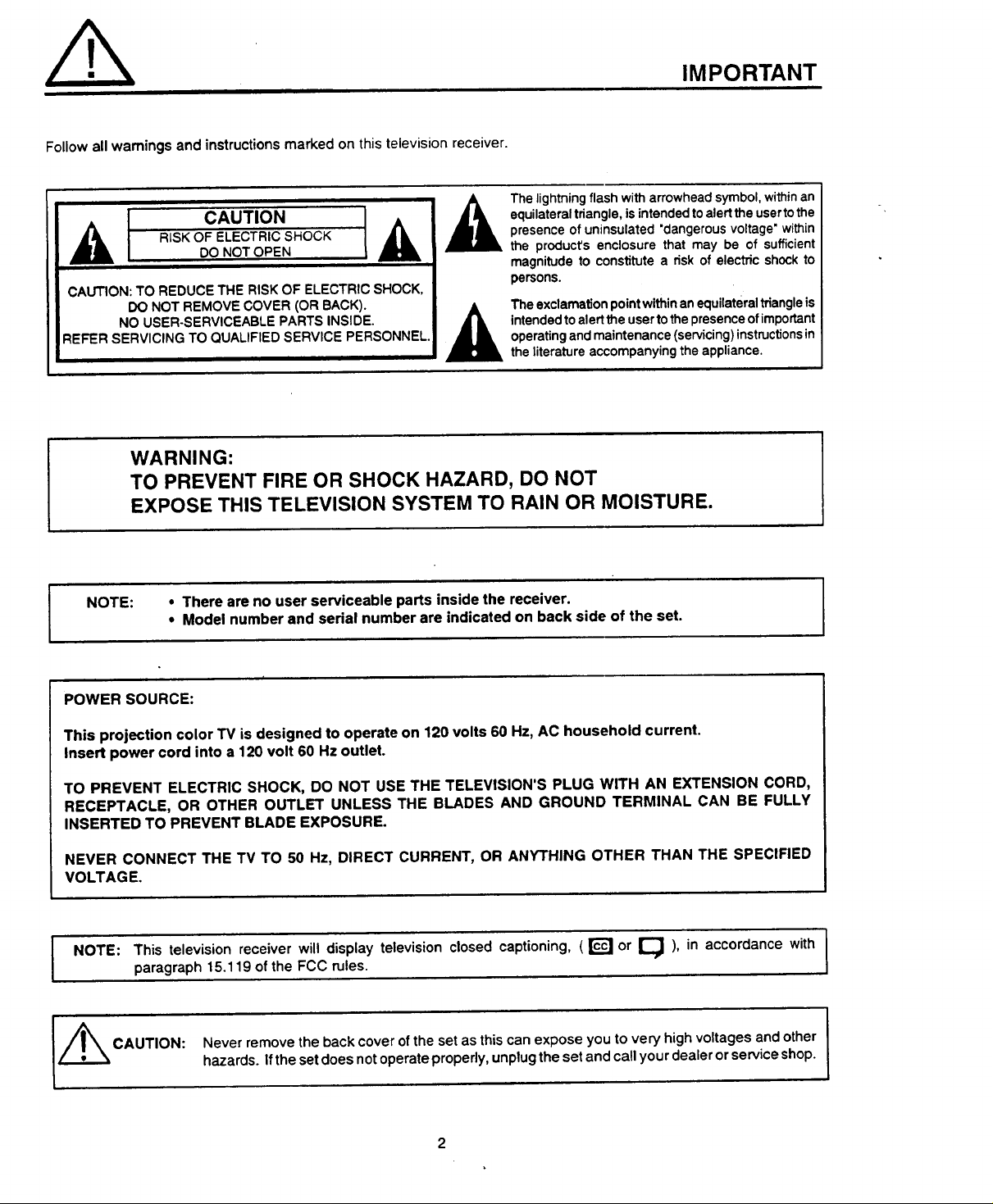
Follow all warnings and instructions marked on this television receiver.
,_ RiSK OF ELECTRICSHOCK
CAUTION: TO REDUCE THE RISK OF ELECTRIC SHOCK,
REFER SERVICING TO QUALIFIED SERVICE PERSONNEL.
I c.o.,o.L&
DO NOT REMOVE COVER (OR BACK).
NO USER-SERVICEABLE PARTS INSIDE.
DO NOT OPEN
WARNING:
TO PREVENT FIRE OR SHOCK HAZARD, DO NOT
EXPOSE THIS TELEVISION SYSTEM TO RAIN OR MOISTURE.
IMPORTANT
Thelightning flash witharrowheadsymbol,withinan
equilateraltriangle,isintendedtoalertthe usertothe
presenceofuninsulated"dangerousvoltage' within
the product'senclosure that may be of sufficient
magnitudeto constitutea nsk of electricshockto
persons.
Theexclamation pointwithinanequilateraltriangleis
intendedtoalertthe userto the presenceofimportant
operatingandmaintenance(servicing)instructionsin
theliteratureaccompanyingtheappliance.
NOTE:
POWER SOURCE:
This projection color TV is designed to operate on 120 volts 60 Hz, AC household current.
Insert power cord into a 120 volt 60 Hz outlet.
TO PREVENT ELECTRIC SHOCK, DO NOT USE THE TELEVISION'S PLUG WITH AN EXTENSION CORD,
RECEPTACLE, OR OTHER OUTLET UNLESS THE BLADES AND GROUND TERMINAL CAN BE FULLY
INSERTED TO PREVENT BLADE EXPOSURE.
NEVER CONNECT THE TV TO 50 Hz, DIRECT CURRENT, OR ANYTHING OTHER THAN THE SPECIFIED
VOLTAGE.
NOTE: This television receiver will display television closed captioning, (_ or Q ), in accordance with I
L_ CAUTION: Never remove the back cover of the set as this can expose you to very high voltages and other
• There are no user serviceable parts inside the receiver.
• Model number and serial number are indicated on back side of the set. I
paragraph 15.119 of the FCC rules.
hazards. Ifthe setdoes not operate properly, unplugthe set and call your dealer or service shop.
I
I
SAFETY TIPS
IMPORTANT SAFEGUARDS
CAUTION: SAFETY POINTS YOU SHOULD KNOW ABOUT
• Read all of these instructions. YOUR HITACHI TELEVISION RECEIVER
• Save these instructions for later use,
• Follow all warnings and instructions marked on the television receiver.
Our reputation has been built on the quality, perlormance, and ease of service of HITACHi television receivers.
Safety is also foremost in our minds in the design of these units. To help you operate these products properly, this section illustrates safety tips which wilt be of benefit
to you. Please read it carefully and apply the knowledge you obtain from it to the proper operation of your HITACHI television receiver.
Please fill out your warranty card at once and mail it tO HITACHI. This will enable HITACHI to notify you promptly in the improbable event that a safety problem should
be discovered in your model of product.
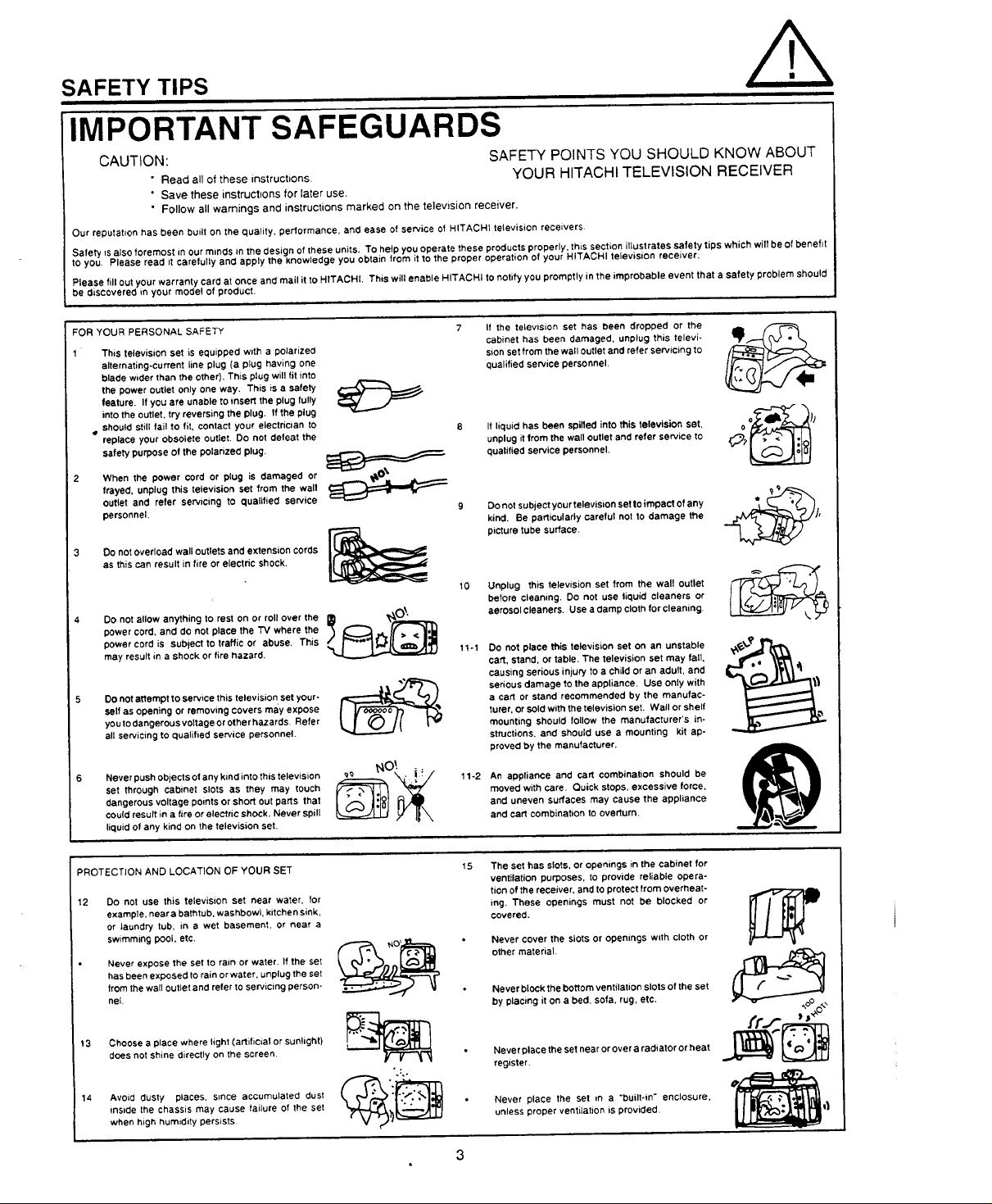
FOR YOUR PERSONAL SAFETY
This television set is equipped with a polarized
alternating-current line plug (a plug having one
blade wider than the other). This plug will fit into
the power outlet only one way. This is a safety
feature. If you are unable to insert the plug fulty
into the outlet, try reversing the plug. If the plug
• should still fail to fit, contact your electrician to
replace your obsotete outlet. Do not defeat the
safety purpose of the polarized plug.
2 When the power cord or plug is damaged or
frayed, unplug this television set from the wall
outlet and refer servicing to qualified service
personnel.
3 OO not overload wall outlets and extension cords
as this can result in fire or electric shock.
Do not allow anything to rest on or roll over the
power cord, and do not place the TV where the
power cord is subject to traffic or abuse. This
may result in a shock or tire hazard.
Do not attempt to service this television, set your-
self as opening or removtng covers may expose
you to dangerous voltage or other hazards. Refer
all servicing to qualified service personnel.
Never push objects o!any kind into this television
set through cabinet slots as they may touch
dangerous voltage points or short OUt parts that
could result in a fire or electric shOCk. Never spill
liquid of any kind on the television set.
9
t0
___o_ tt-t
..2
If the television set has been dropped or the
cabinet has been damaged, unplug this televi-
sion set from the wall outlet and refer servicing to
quaJified service personnel.
Jfliquid has been spilled into this television set,
unplug itfrom the wall outlet and refer service to
qualified service personnel.
Do not subject your television set to impact of any
kind. Be particularly careful not to damage the
picture tube surface,
Unplug this television set from the wall outlet
before cleaning. Do not use liquid cleaners or
aerosol cleaners. Use a(:lamp cloth for cleaning.
Co not place this television set on an unstable
cart, stand, or table. The television set may fall,
causing serious injury tO a child or an adult, and
serious damage to the appliance. Use only with
a cart or stand recommended by the manufac-
turer, or sold with the television set. Wall or shelf
mounting should follow the manufacturer's in-
structions, .and should use a mounting kit ap-
proved by the manufacturer.
An appliance and cart combination should be
moved with care. Quick stops, excessive force,
and uneven surfaces may cause the appliance
and cart combination to overturn.
o _}'J
PROTECTION AND LOCATION OF YOUR SET
12 Do not use this television set near water, for
example, near a bathtub, washbowl, kitchen sink,
or laundry tub, in a wet basement, or near a
swimming pool. etc.
Never expose the set to rain or water, tf the set
has been exposed to rain or water, unplug the set
from thewall outlet and refer to servicing person-
nel.
13 Choose a place where light (artificial or sunlight)
does not shine directly on the screen.
14 Avoid dusty places, since accumulated dust
inside the chassis may cause failure of the set
when high humidity persists
15
The set has slots, or openings in the cabinet for
ventilation purposes, to provide reliable opera-
tion of the receiver, and to protect from overheat-
ing. These openings must not be blocked or
covered.
Never cover the slots or openings with cloth or
other material.
Never block the bottom ventilation slots of the set
by placing it on a bed, sofa. rug, etc.
Neve r place the set near or over a radiator or heat
register.
Never place the set in a "built-in" enclosure,
unless proper ventilation is provided.
SAFETY TIPS
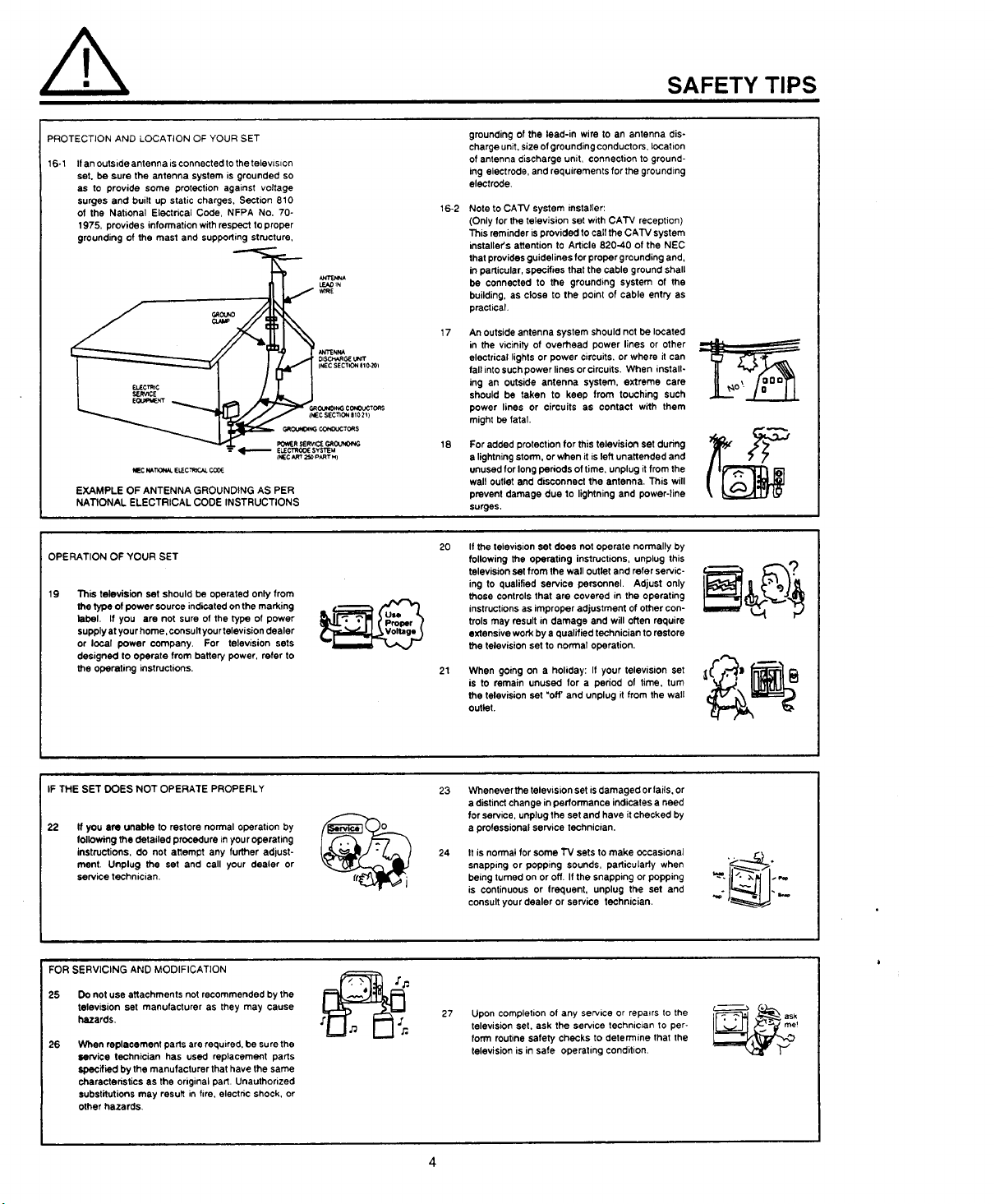
PROTECTION AND LOCATION OF YOUR SET
16-1 If an outside antenna is connected to the television
set. be sure the antenna system is grounded so
as to provide some protection against voltage
surges and built up static charges, Section 810
of the National Electrical Code, NFPA No. 70-
1975, provide s information with respect toproper
grounding of the mast and supporting structure,
!_i.=,., _ ELECT'ROOESYSI1_M
_ECW_IrK_'W_.IELEC'_C_LCCOE
EXAMPLE OF ANTENNA GROUNDING AS PER
NATIONAL ELECTRICAL CODE INSTRUCTIONS
OPERATION OF YOUR SET
19 This television set should be operated only from
the type of power source indicated on the marking
label, If you are not sure of the type of power
supply at your home, consult your television dealer
or local power company. For television sets
designed to operate from batte_ power, refer to
the operating instructions.
fNEC_ 250PARTH)
grounding of the lead-in wire to an antenna dis-
charge unit, size of grounding conductors, location
of antenna discharge unit, connection to ground-
ing electrode, and requirements for the grounding
electrode.
16-2
Note to CATV system installer:
(Only for the television set with CATV reception)
This reminder is provided to calf the CATV system
installer's atlention to Article 820-40 of the NEC
that provides guidelines for prober grounding and,
in particular, specifies that the cable ground shall
be connected to the grounding system of the
building, as close to the point of cable entry as
practical.
17
An outside antenna system should not be located
in the vicinity of overhead power lines or other
electrical lights or power circuits, or where it can
fall into such power lines orcirouits. When install-
ing an outside antenna system, extreme care
should be taken to keep from touching such
power lines or circuits as contact with them
might be fatal.
18
For added protection for this television set during
a lightning storm, or when it is left unattended and
unused for long periods oftime. unplug it from the
walt outlet and disconnect the antenna. This will
prevent damage due to lightning and power-line
surges,
2O21If the television set does not operate normally by
following the operating instructions, unplug this
television set from the wall outlet and refer servic-
ing to qualified service personnel. Adjust only
those controls that are covered in the operating
instructions as improper adjustment of other con-
trois may result in damage and will often require
extensive work by a qualified technician to restore
the television set to normal operation.
When going on a holiday: If your television set
is to remain unused for a pedod of time, turn
the television set "off' and unplug it from the wall
outlet.
IF THE SET DOES NOT OPERATE PROPERLY
22
If you are unable to restore normal operation by
following the detailed procedure inyour operating
instructions, do not attempt any further adjust-
ment. Unplug the set and call your dealer or
service technician.
FOR SERVICING AND MODIFICATION
25 Do not use attachments not recommended by the
television set manufacturer as they may cause
hazards.
26
When replacement parts are required, be sure the
service technician has used replacement parts
specified by the manufacturer that have the same
characteristics as the original part. Unauthorized
substitutions may result in fire, electric shock, or
other hazards.
23
Whenever the television set is damaged or fails, or
a distinct change in performance indicates a need
for service, unplug the set and have it checked by
a professional service technician.
24
It is normal for some TV sets to make occasional
snapp,ng or popping sounds, particuiedy when
being turned on or off. If the snapping or popping
is continuous or frequent, unplug the set and
consult your dealer or service technician.
27 Upon completion of any service or repairs to the
television set, ask the service technician to per-
form routine safety checks to determine that the
television is in safe operating condition.
4
PICTURE CAUTIONS
Continuous on-screen displays such as
video games, stock market quotations,
computer generated graphics, and other
fixed (non-moving) patterns can cause per-
WARNING
manent damage to projection television
receivers. Such "PATTERN BURNS" con-
stitute misuse and are NOT COVERED by
your Hitachi Factory Warranty.
When using the Picture-in-Picture function, the sub-picture should not be left permanently
in one corner of the screen or a "pattern burn" may develop over a long period of time.
This projection television receiver was intended mainly for the private viewing of programs
broadcast by TV stations and cable companies and programs from other video sources.
Public viewing may require prior authorization from the broadcaster or owner of the video
program.
ACCESSORIES
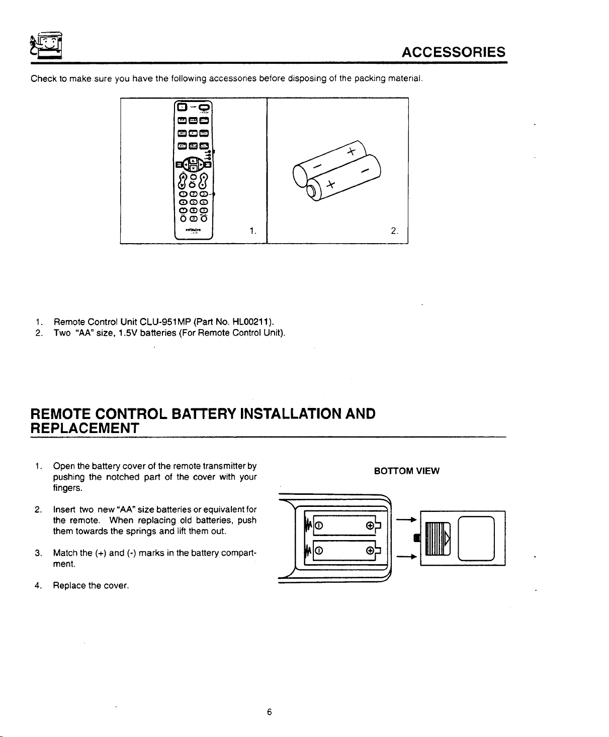
Check to make sure you have the following accessories before disposing of the packing material.
tm_
O(_O-
G:)_E)O
OG:)O
OoD
1. 2.
1. Remote Control Unit CLU-951MP (Part No. HL00211).
2. Two "AA" size, 1.5V batteries (For Remote Control Unit).
REMOTE CONTROL BATTERY INSTALLATION AND
REPLACEMENT
1.
Open the battery cover of the remote transmitter by
pushing the notched part of the cover with your
fingers.
2.
Insert two new "AA" size batteries or equivalent for
the remote. When replacing old batteries, push
them towards the springs and lift them out.
3.
Match the (+) and (-) marks in the battery compart-
ment.
4. Replace the cover.
BOTTOM VIEW
HOW TO SET UP YOUR NEW HITACHI PROJECTION TV
ANTENNA
Unless your TV is connected to a cable TV system or to a centralized antenna system, a good outdoor color TV antenna
is recommended for the best performance. However, if you are located in an exceptionally good signal area that is free
from interference and multiple image ghosts, an indoor antenna may be sufficient.
LOCATION
Select an area where sunlight or bright indoor illumination will not fall directly on the picture screen. Also, be sure that
the location selected allows a free flow of air to and from the perforated back cover of the set.
To avoid cabinet warping, cabinet color changes, and increased chance of set failure, do not place the TV where
temperatures can become excessively hot. For example, in direct sunlight or near a heating appliance, etc.
VIEWING
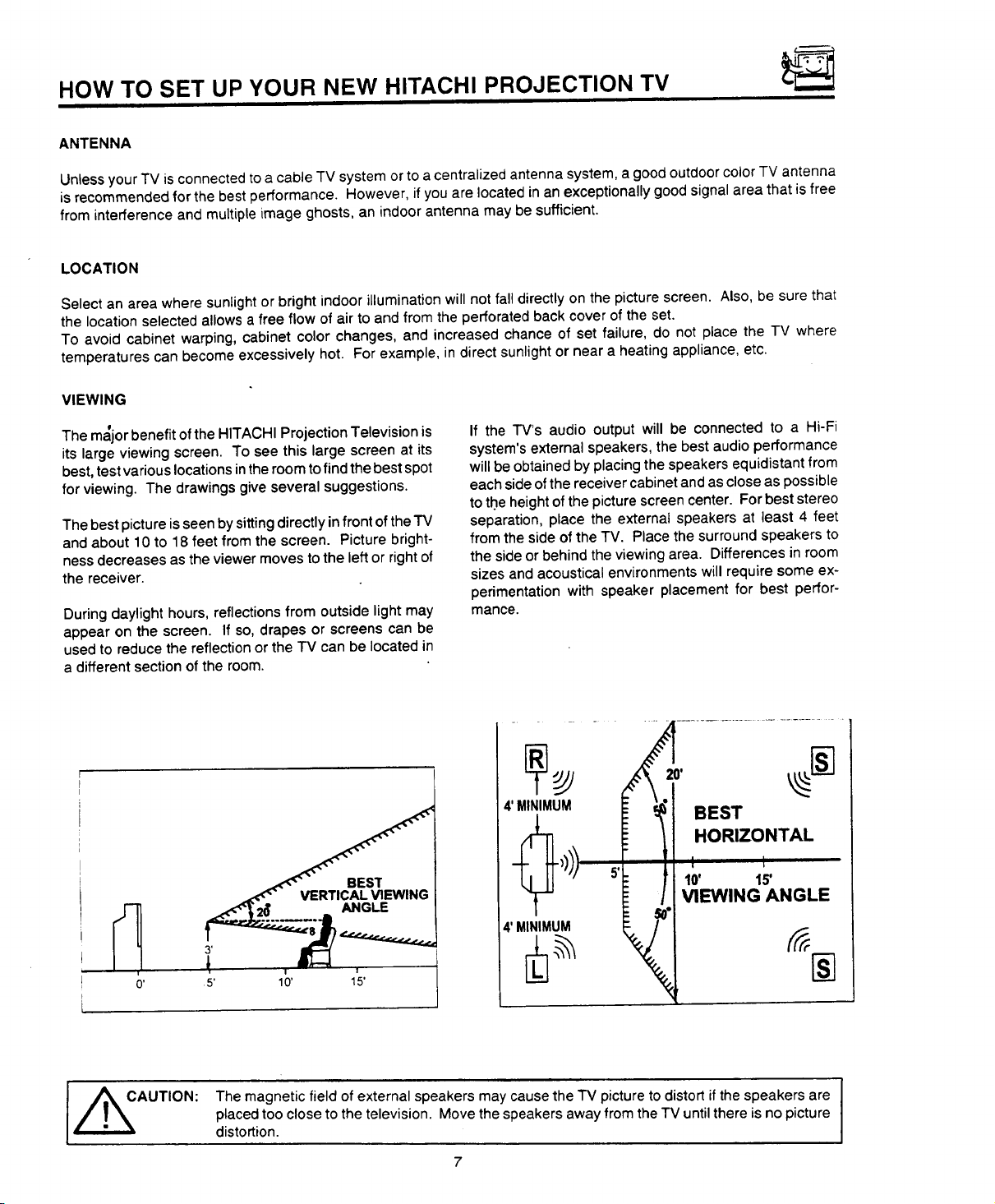
The m,_jor benefit of the HITACHI Projection Television is
its large viewing screen. To see this large screen at its
best, test various locations in the room to find the best spot
for viewing. The drawings give several suggestions.
The best picture is seen by sitting directly in frontof the TV
and about 10 to 18 feet from the screen. Picture bright-
ness decreases as the viewer moves to the left or right of
the receiver.
During daylight hours, reflections from outside light may
appear on the screen. If so, drapes or screens can be
used to reduce the reflection or the TV can be located in
a different section of the room.
If the TV's audio output will be connected to a Hi-Fi
system's external speakers, the best audio performance
will be obtained by placing the speakers equidistant from
each side of the receiver cabinet and as close as possible
to the height of the picture screen center. For best stereo
separation, place the external speakers at least 4 feet
from the side of the TV. Place the surround speakers to
the side or behind the viewing area. Differences in room
sizes and acoustical environments will require some ex-
perimentation with speaker placement for best perfor-
mance.
4'MINIMUM _" _r_! BEST
HORIZONTAL
VIEWING ANGLE
I _AUTION:
The magnetic field of external speakers may cause the TV picture to distort if the speakers are I
placed too close to the television. Move the speakers away from the TV until there is no picture
distortion.
7
I
HOOK-UP CABLES AND CONNECTORS
Most video/audio connections between components can
be made with shielded video and audio cables that have
phono connectors. For best performance, video cables
should use 75-ohm coaxial shielded wire. Cables can be
purchased from most stores that sell audio/video prod-
ucts. Below are illustrations and names of common con-
nectors.
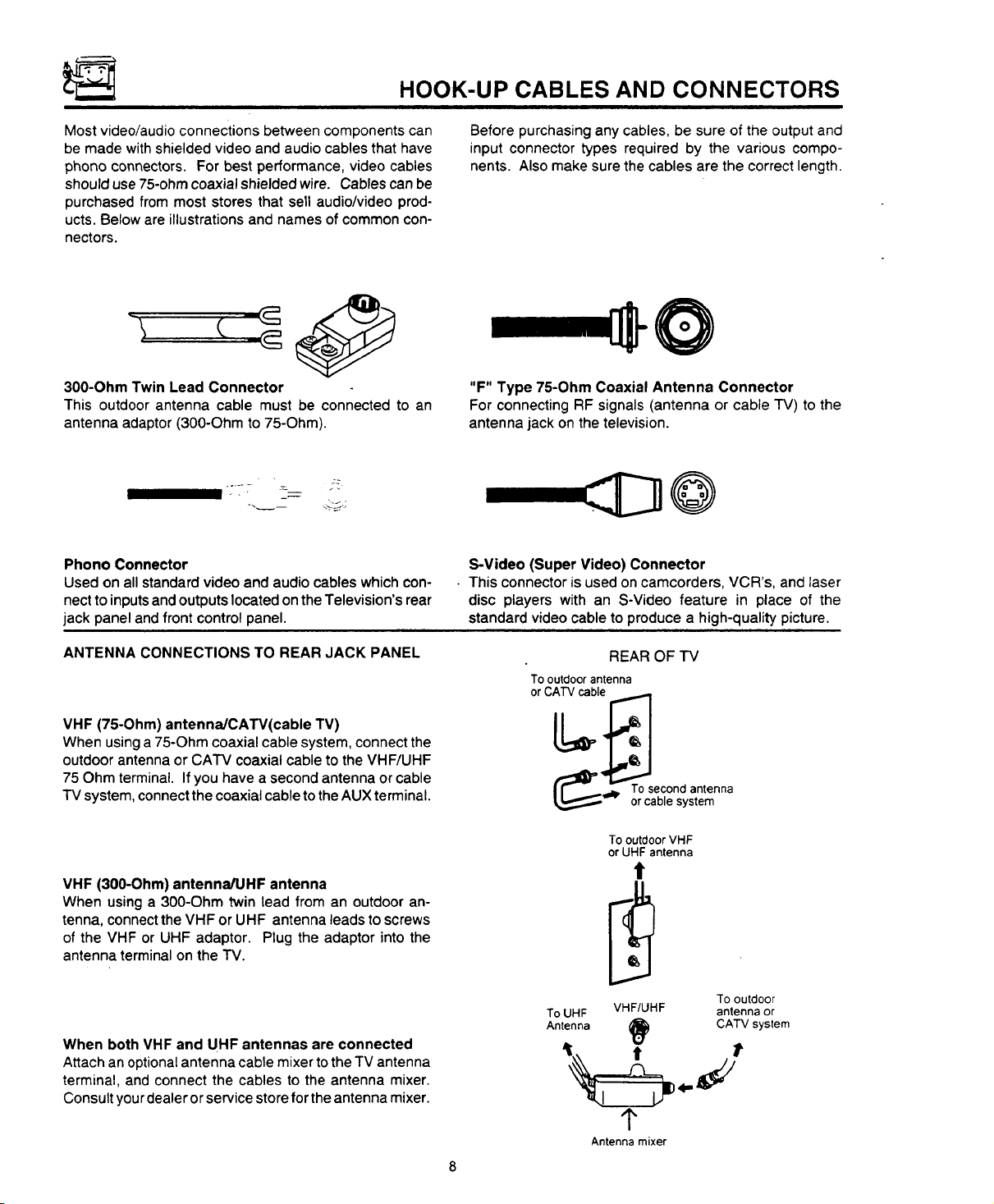
300-Ohm Twin Lead Connector
This outdoor antenna cable must be connected to an
antenna adaptor (300-Ohm to 75-Ohm).
Phono Connector
Used on all standard video and audio cables which con-
nectto inputsand outputs located on the Television's rear
jack panel and front control panel.
Before purchasing any cables, be sure of the output and
input connector types required by the various compo-
nents. Also make sure the cables are the correct length.
"F" Type 75-Ohm Coaxial Antenna Connector
For connecting RF signals (antenna or cable TV) to the
antenna jack on the television.
@
S-Video (Super Video) Connector
• This connector is used on camcorders, VCR's, and laser
disc players with an S-Video feature in place of the
standard video cable to produce a high-quality picture.
ANTENNA CONNECTIONS TO REAR JACK PANEL
VHF (75-Ohm) antenna/CAW(cable TV)
When using a 75-Ohm coaxial cable system, connect the
outdoor antenna or CATV coaxial cable to the VHF/UHF
75 Ohm terminal. If you have a second antenna or cable
IV system, connectthe coaxial cable tothe AUX terminal.
VHF (300-Ohm) antenna/UHF antenna
When using a 300-Ohm twin lead from an outdoor an-
tenna, connect the VHF or UHF antenna leads to screws
of the VHF or UHF adaptor. Plug the adaptor into the
antenna terminal on the TV.
When both VHF and UHF antennas are connected
Attach an optional antenna cable mixer tothe TV antenna
terminal, and connect the cables to the antenna mixer.
Consult yourdealer orservice store for the antenna mixer.
REAR OF TV
To outdoor antenna
or CATV cable
__ oTrOCseb_Ondsatntenna
To outdoor VHF
or UHF antenna
To UHF VHF/UHF antenna or
Antenna _) CA'IV system
To outdoor
t t
1"
Antenna mixer
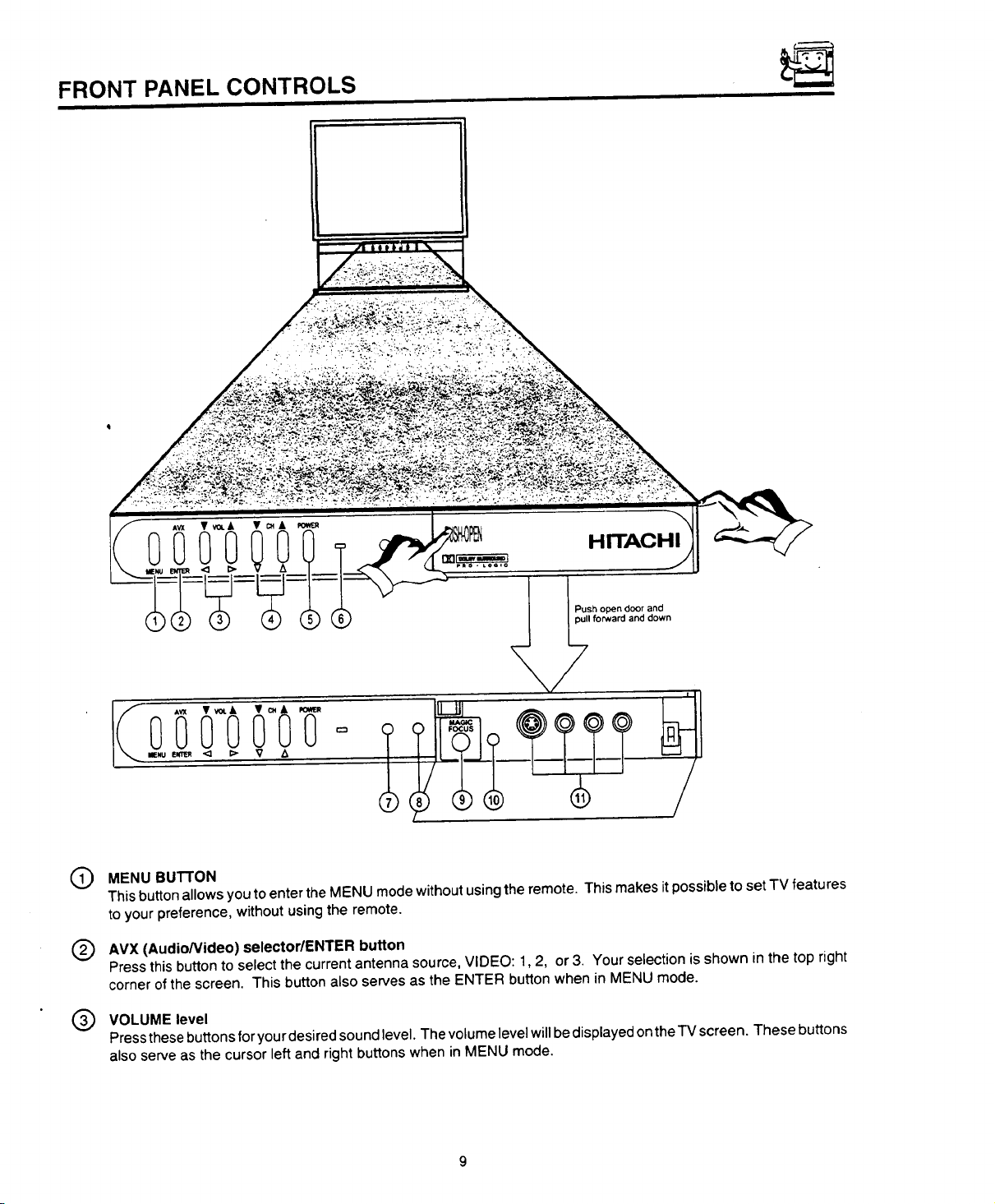
FRONT PANEL CONTROLS
• ,. : -. ,
0-
HITACHI
pull forward and down
[ Push open door and
oiiiiIY
MENU BUTTON
(9
This button allows you to enter the MENU mode withoutusing the remote. This makes itpossible to set TV features
to your preference, without usingthe remote.
AVX (Audio/Video) selector/ENTER button
®
Press this button to select the current antenna source, VIDEO: 1,2, or 3. Your selection is shown in the top right
corner ofthe screen. This button also serves as the ENTER button when in MENU mode.
VOLUME level
®
Press these buttons for you rdesired sound level. The volume level will be displayed on the TV screen. These buttons
also serve as the cursor left and right buttons when in MENU mode,
FRONT PANEL CONTROLS
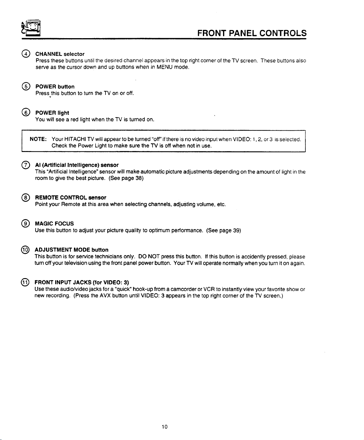
CHANNEL selector
Press these buttons until the desired channel appears in the top right corner of the TV screen. These buttons also
serve as the cursor down and up buttons when in MENU mode.
POWER button
Press this button to turn the "IV on or off.
POWER light
You will see a red light when the TV is turned on.
I NOTE: YourHITACHITVwillappeartobeturned"off"ifthereisnovideoinputwhenVIDEO:l,2, or3 is selected.
Check the Power Light to make sure the TV is off when not in use.
AI
(Artificial Intelligence) sensor
This "Artificial Intelligence"sensorwillmake automaticpictureadjustmentsdepending on theamount of lightin the
roomto givethe bestpicture. (See page 38)
@ REMOTE CONTROL sensor
Pointyour Remoteat this area whenselectingchannels,adjustingvolume,etc.
MAGIC FOCUS
Use this button to adjust your picture quality to optimum performance. (See page 39)
ADJUSTMENT MODE button
This button is for service technicians only. DO NOT press this button. If this button is accidently pressed, please
turn off your television using the front panel power button. Your "IV willoperate normally when you turn iton again.
@ FRONT INPUT JACKS (for VIDEO: 3)
Use these audio/video jacks for a "quick" hook-up from a camcorder or VCR to instantly view your favorite show or
new recording. (Press the AVX button until VIDEO: 3 appears in the top right corner of the TV screen.)
10

FRONT PANEL JACKS AND CONNECTIONS
The front panel jacks are provided as a convenience to allow you to easily connect a camcorder or VCR as shown in the
tollowing examples:
S-VHS Video camera
o @eee
S-VIDEO
S - INPUT
(Optional, see note)
\
T
I
S-VHS V L R
I@ooo
(Back of VCR)
OUTPUT
o G)ooo
I ! S-VIDEO V L R
/ oj # VDO
NOTE:
back picture may be abnormal, ff you have a S-VHS VCR, use the S-INPUT cable Jnplace of the standard
video cable.
c`nse c nnect` c r ugswher c nr ec.`r gt r°r tpane `ackS fy h° `aye I
11
F
O _ REAR SPEAKER
__J'<'>!. 8o ONLY
VHFIUHF
TO CONVERTEF
©
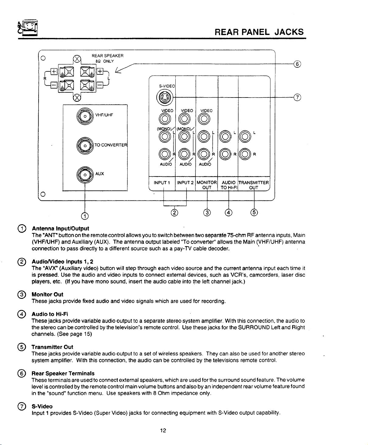
REAR PANEL JACKS
®
@
310 ITRANSMITTER
-II-FII OUT
®',
®
Antenna Input/Output
The "ANT" button onthe remotecontrolallowsyou toswitchbetweentwo separate75-ohmRFantennainputs,Main
(VHF/UHF) andAuxiliary(AUX). The antennaoutputlabeled"Toconverter"allowstheMain(VHF/UHF) antenna
connectiontopass directlytoa differentsourcesuchasa pay-TVcabledecoder.
AudioNideo Inputs 1, 2
®
The "AVX" (Auxiliary video) button will step through each video source and the current antenna input each time it
is pressed. Use the audio and video inputs to connect external devices, such as VCR's, camcorders, laser disc
players, etc. (If you have mono sound, insert the audio cable into the left channel jack.)
Monitor Out
®
These jacks provide fixed audioand video signals whichare usedfor recording.
Audio to Hi-Fi
®
These jacks provide variable audio output to a separate stereo system amplifier. With this connection, the audio to
the stereo can becontrolled bythe television's remote control. Use these jacks for the SURROUND Left and Right
channels. (See page 15)
Transmitter Out
®
These jacks provide variable audio output to a set of wireless speakers. They can also be used for another stereo
system amplifier. With this connection, the audio can be controlled by the televisions remote control.
Rear Speaker Terminals
®
These terminals are used to connect external speakers, whichare used for the surround sound feature. The volume
level is controlled by the remote control main volume buttons and also by an independent rear volume feature found
in the "sound" function menu. Use speakers with 8 Ohm impedance only.
S-Video
Input 1 provides S-Video (Super Video) jacks for connecting equipment with S-Video output capability.
12
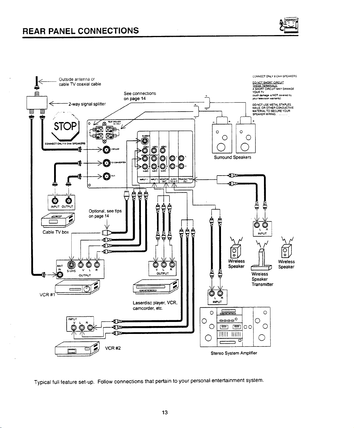
REAR PANEL CONNECTIONS
cable TV coaxial cable
__ Outside antenna or
on page 14
2-way signal splitte_
See connections
Surround Speakers
CONNECT ONLY 8 Ohm SPEAKERS
DO NOT SHORT CIRCUrT
THESE TERMINALS
A SHORT CIRCUIT MAY DAMAGE
YOUR "IV
(SUCh _a re, age ,s NOT covereu by
yOUr lelevls,on warrar11y)
OO NOT USE METAL STAPLES
NAILS, OR OTRER CONDUCTIVE
MATERIAL TO SECURE YOUR
SPEAKER WIRING ............
=_.C __ableTV box ,
VCR #1
[I"PT, R l _---_
L_---__--_ _F_
! _ = vcR#2
I
Optional, see tips
Laserdiscplayer, VCR,
camcorder,etc.
wireless
Speaker
[_ Wireless
Speaker
Wireless
Speaker
Transmitter
r-----'-i
o
O
I
I
_O
O
111111IIIIII
O
Stereo System Amplifier
D
O
O
O
O
Typical full feature set-up. Follow connections that pertain to your personal entertainment system.
13
REAR SPEAKER TERMINAL CONNECTIONS
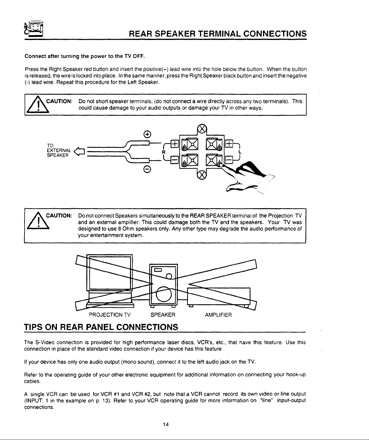
Connect after turning the power to the TV OFF.
Press the Right Speaker red button and insert the positive(+) lead wire into the hole below the button. When the button
is released, the wire islocked into place. In the same manner, press the Right Speaker black button and insert the negative
(-) lead wire. Repeat this procedure for the Left Speaker.
,/_AUTION: Do not short speaker terminals, (do not connect a wire directly across any two terminals). This
TO
EXTERNAL q_]
SPEAKER
could cause damage to your audio outputs or damage your TV in other ways.
Do not connect Speakers simultaneously to the REAR SPEAKER terminal of the Projection TV
and an external amplifier. This could damage both the TV and the speakers. Your TV was
designed to use 8 Ohm speakers only. Any other type may degrade the audio performance of
your entertainment system.
C
PROJECTION TV SPEAKER AMPLIFIER
TIPS ON REAR PANEL CONNECTIONS
The S-Video connection is provided for high performance laser discs, VCR's, etc., that have this feature. Use this
connection in place of the standard video connection if your device has this feature.
If your device has only one audio output (mono sound), connect it to the left audio jack on the TV.
Refer to the operating guide of your other electronic equipment for additional information on connecting your hook-up
cables.
A single VCR can be used for VCR #1 and VCR #2, but note that a VCR cannot record its own video or line output
(INPUT: 1 in the example on p. 13). Refer to your VCR operating guide for more information on "line" input-output
connections.
14
AUDIO SYSTEM SET-UP ,,.E:_
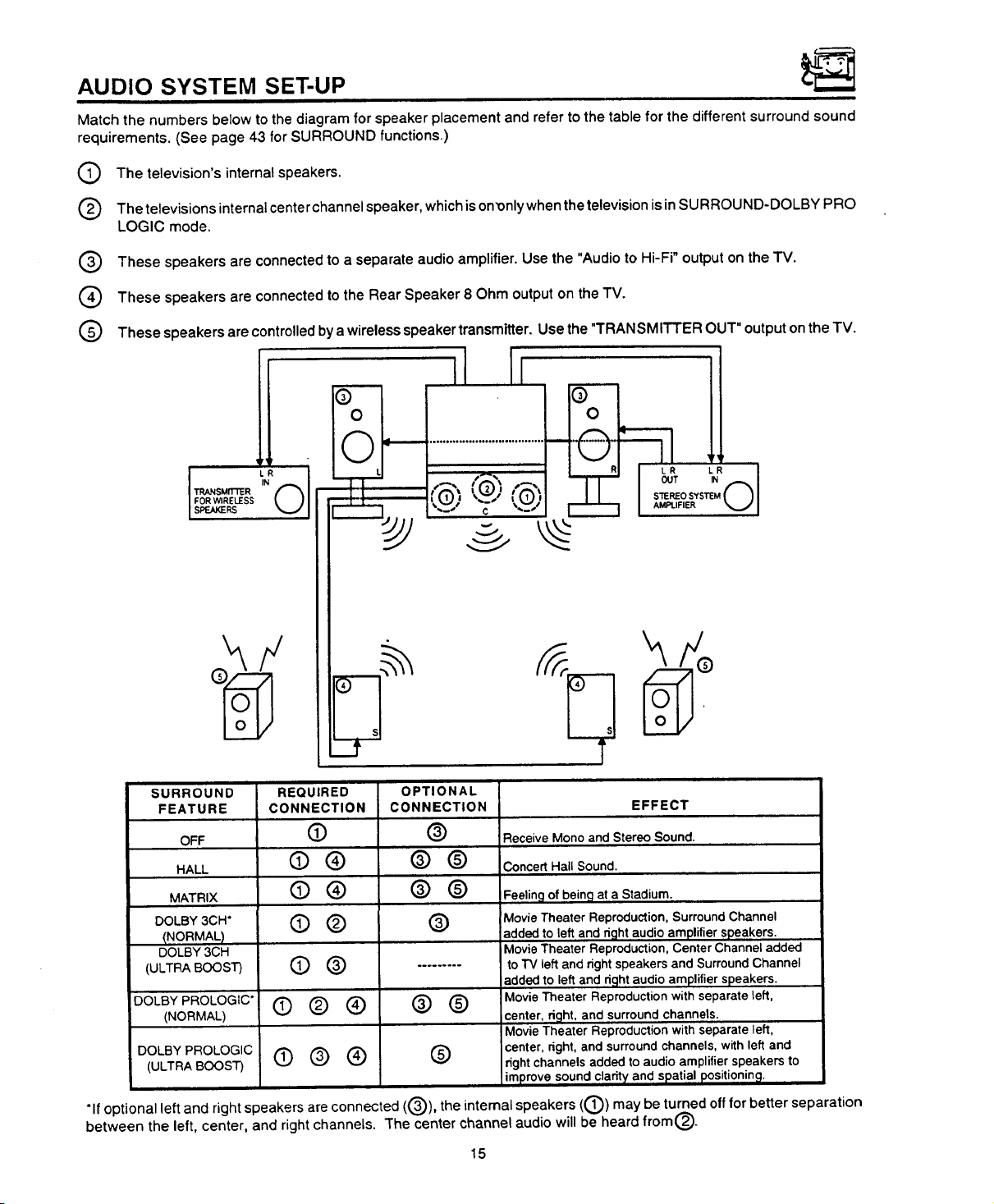
Match the numbers below to the diagram for speaker placement and refer to the table for the different surround sound
requirements. (See page 43 for SURROUND functions.)
The television's internal speakers.
The televisions internal center channel speaker, which is on'only when the television is in SURROU ND-DOLBY PRO
LOGIC mode.
These speakers are connected to a separate audio amplifier. Use the "Audio to Hi-Fi" output on the TV.
®
These speakers are connected to the Rear Speaker 8 Ohm output on the TV.
®
@
These speakers are controlledby a wireless speaker transmitter. Use the "TRANSMITTER OUT" output on the TV.
p
0 @ I
SURROUND
FEATURE
OFF
HALL
MATRIX
DOLBY 3CH*
_NORMAL)
DOLBY 3CH
(ULTRA BOOST)
DOLBY PROLOGIC*
(NORMAL)
DOLBY PROLOGIC
(ULTRA BOOST)
*If optional left and right speakers are connected ((3)), the internal speakers ((_) may be turned off for better separation
between the left, center, and right channels. The center channel audio will be heard from®.
REQUIRED
CONNECTION
O
@®
@®
©®
©®
©®®
(])@®
OPTIONAL
CONNECTION
®
®®
®@
®
®®
®
EFFECT
Receive Mono and Stereo Sound.
Concert Hall Sound.
Feeling of being at a Stadium.
Movie Theater Reproduction, Surround Channel
added to left and d_]ht audio amplifier speakers.
Movie Theater Reproduction, Center Channel added
to TV left and right speakers and Surround Channel
added to left and d_]ht audio amplifier speakers.
Movie Theater Reproduction with separate left,
center, dght, and surround channels.
Movie Theater Reproduction with separate left,
center, right, and surround channels, with left and
right channels added to audio amplifier speakers to
Improve sound clarity and spatial positioning.
15
THE REMOTE CONTROL (CLU-951MP)
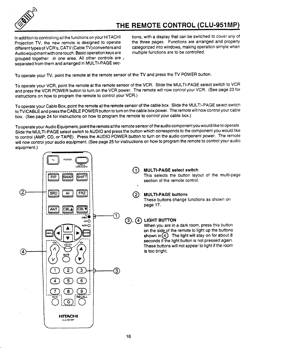
Inaddition to controlling all the functions on your HITACHI
Projection TV, the new remote is designed to operate
different types of VCR's, CATV (Cable TV) converters and
Audio equipment with one touch. Basic operation keys are
grouped together in one area. All other controls are,
separated from them and arranged in MULTI-PAGE sec-
To operate your TV, point the remote at the remote sensor of the TV and press the TV POWER button.
To operate your VCR, point the remote at the remote sensor of the VCR. Slide the MULTI-PAGE select switch to VCR
and press the VCR POWER button to turn on the VCR power. The remote will now control your VCR. (See page 23 for
instructions on how to program the remote to control your VCR.)
To operate your Cable Box, point the remote atthe remote sensor of the cable box. Slide the MULTI-PAGE select switch
to TV/CABLE and press the CABLE POWER button toturn on the cable box power. The remote will now control your cable
box. (See page 24 for instructions on how to program the remote to control your cable box.)
To operate your Audio Equipment, point the remote at the remote sensor of the audio component you would like to operate.
Slide the MULTI-PAGE select switch to AUDIO and press the button which corresponds to the component you would like
to control (AMP, CD, or TAPE). Press the AUDIO POWER button to turn on the audio component power. The remote
will now control your audio equipment. (See page 25 for instructions on how to program the remote to control your audio
equipment.)
CABLE
VCPJAUDIO
r ......................
tions, with a display that can be switched to cover any of
the three pages. Functions are arranged and properly
categorized into windows, making operation simple when
multiple functions are to be controlled.
MULTI-PAGE select switch
This selects the button layout of the multi-page
section ofthe remote control.
®
®
I
Q
__Q.
', I
_) _i _ RECALL
•_Q:0
HITACHI
CLU'951MP
MULTI-PAGE buttons
@
These buttons change functions as shown on
page 17.
@
®,®
D
LIGHT BUTTON
When you are in a dark room, press this button
on the side of the remote to light up the buttons
shown in@. The light will stay on
seconds if the light button is not pressed again.
These buttons will not appear to light if the room
is too bright.
for about 8
, ®
16
 Loading...