

Hitachi 60SBX78B, 50SBX78B Owner’s Manual
:_ROJECTION COLOR TV
DPERATING GUIDE
IMPORTANT SAFEGUARDS
FIRST TIME USE
THE GENIUS
REMOTE CONTROL
ULTRATEC BIT-MAP
ON-SCREEN DISPLAY
2-4
5-21
22-33
34-81
ASK
MEI
USEFUL INFORMATION INDEX 82-87
Follow all wamings and instructionsmarked on thisprojectiontelevision.
The lightning flash with awowhead symbol, within an equilateral
triangle, is intended to alert the user to the presence of uninsulated
"dangerous voltage" within the product's enc_sura that may be of a
sufficientmagnitude to constitute a risk of electric shock to persons.
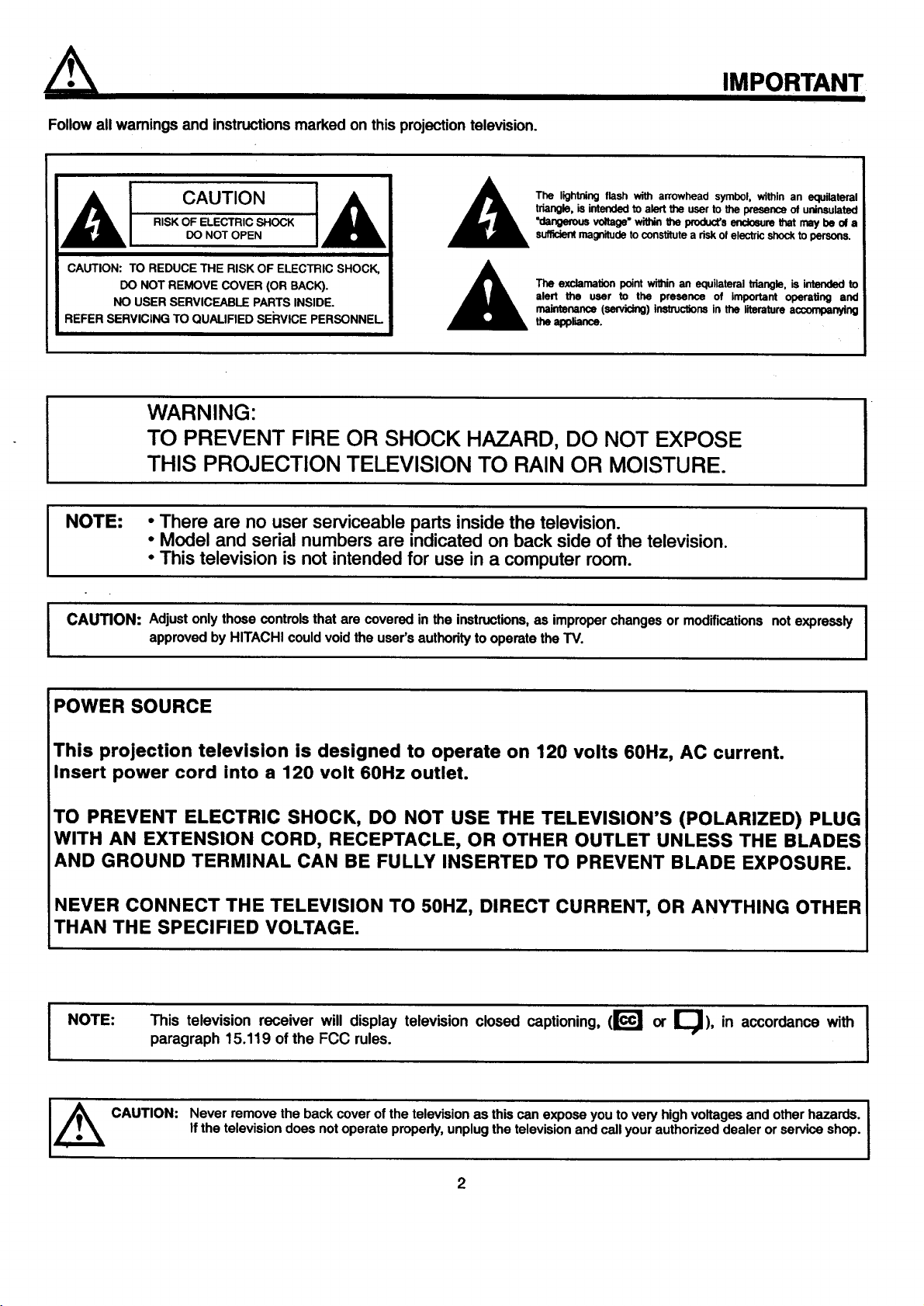
CAUTION: TO REDUCE THE RISK OF ELECTRIC SHOCK,
DO NOT REMOVE COVER (OR BACK).
NO USER SERVICEABLE PARTS INSIDE.
REFER SERVICING TO QUALIFIED SERVICE PERSONNEL
The exclamation point within an equilateral triangle, is intended to
alert the user to the presence of important operating and
maintenance (servicing) instructions in the literature a_nying
the appliance.
WARNING:
TO PREVENT FIRE OR SHOCK HAZARD, DO NOT EXPOSE
THIS PROJECTION TELEVISION TO RAIN OR MOISTURE.
NOTE: • There are no user serviceable parts insidethe television.
• Model and serial numbers are indicatedon back side of the television.
• This television is not intendedfor use in a computer room.
IMPORTANT
I CAUTION: Adjust only those controls that are covered in the instructions,as improper changes or modifications not expressly
approved by HITACHI could void the user's authodty to operate the TV.
POWER SOURCE
This projection television is designed to operate on 120 volts 60Hz, AC current.
Insert power cord into a 120 volt 60Hz outlet.
TO PREVENT ELECTRIC SHOCK, DO NOT USE THE TELEVISION'S (POLARIZED) PLUG
WITH AN EXTENSION CORD, RECEPTACLE, OR OTHER OUTLET UNLESS THE BLADES
AND GROUND TERMINAL CAN BE FULLY INSERTED TO PREVENT BLADE EXPOSURE.
NEVER CONNECT THE TELEVISION TO 50HZ, DIRECT CURRENT, OR ANYTHING OTHER
THAN THE SPECIFIED VOLTAGE.
NOTE:
This television receiver will display television closed captioning, (r_l or _), in accordance with I
paragraph 15.119 of the FCC rules.
I
CAUTION:
Never remove the back cover of the television as this can expose you to very highvoltages and other hazards. I
I
If the television does not operate properly, unplug the television and call your authorized dealer or service shop.
I
2
SAFETY TIPS
IMPORTANT SAFEGUARDS
CAUTION:
• Read all of these instructions.
• Save these instructions for later use.
• Follow all wamings and instructions marked
on the television.
Our reputation has been built on the quality, performance, and ease of service of HITACHI televisions.
Safety is also foremost in our minds in the design of these units.To help you operate these products properly, this section illustrates safety tips which
will be of benefit to you. Please read it carefully and apply the knowledge you obtain from it to the proper operation of your HITACHI television.
Please fill out your warranty card and mail it to HITACHI. This will enable HITACHI to notify you promptly in the improbable event that a safety
problem should be discovered in your product model.
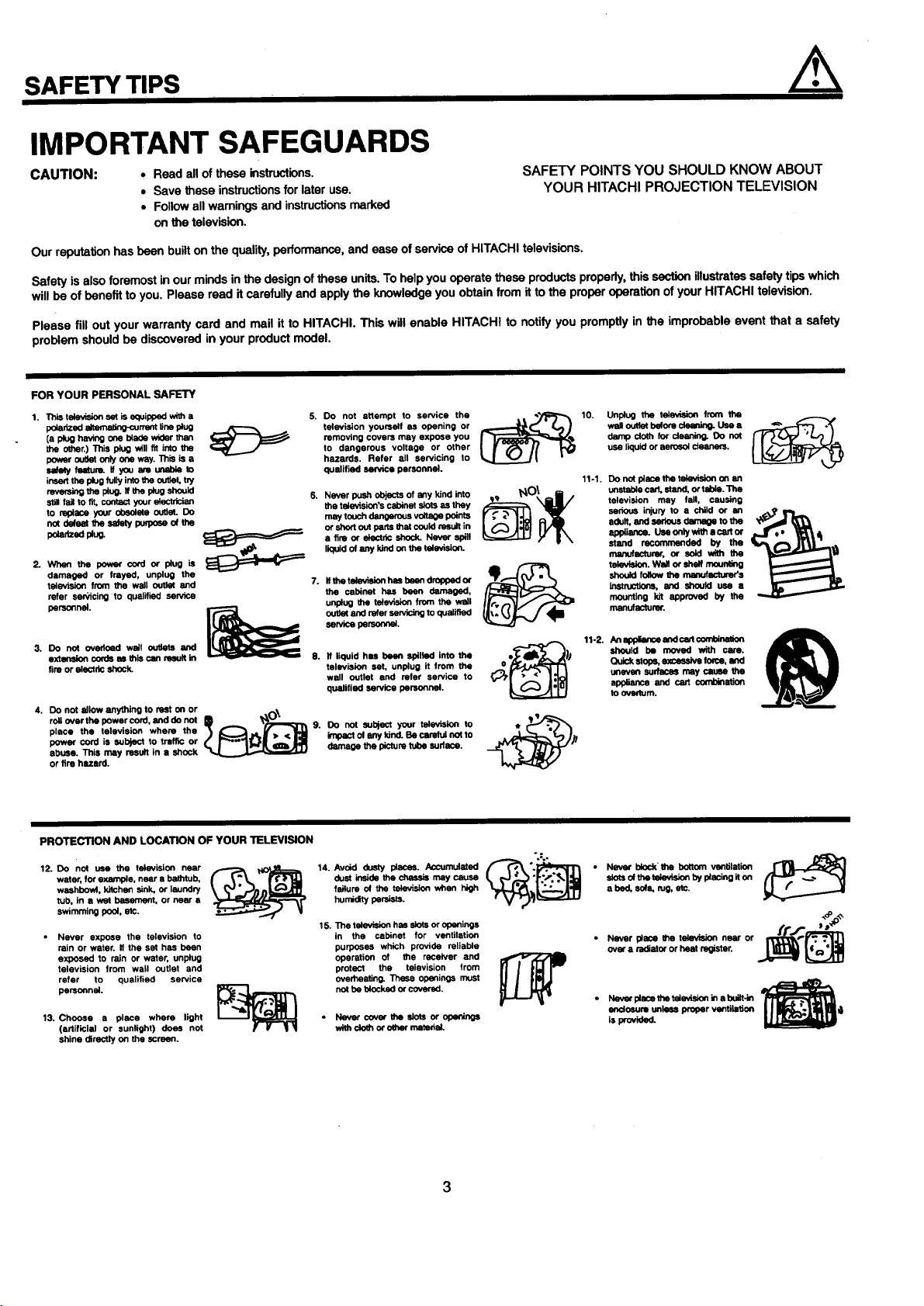
FOR YOUR PERSONAL SAFETY
1. This television se_ is equipped with a
peaa_ed eltemeting-corrent ,he plug
(a plug having one blade wider than
the other.) This plug will fit into the
power outk)t only one way. This is a
setety feetum. If you am unable to
insert the plug fully into the outlet, try
m_ing the p_ug.If the p4ugshould
s_ll fail to fit, contact your electrician
to replace your obsolete outlet. Do
not pefset the _dety puq_ose of the
peladzedpk_
2. When the peworcord or plug is
damaged or frayed, unplug the
tele_Asion from the wall outlet and
refer san;'icing to qualified service
personnel.
3. Do not ovedoed wall outlets and
axtsnelon cords as this can msuJt in
fire or electric shock.
4. DO not allow anything to rest on or .,_\
roll over the power cord, and do not
place the television where the
power cord is subjecl to traffic or
abuse. This may result in s shock
or fire hezerd.
5. Do not attempt to service the . ._;;:zj_% 10. Unplug the talevis_n from the _.._._.
removing covers may expose you damp cloth for dsening. Do not
television yourself as opening or wallootlet belore c_ t._ee
to dangerous voltage or other use liquid or aerosol cleaners.
hazards. Refer all servicing to
qualified service personnel.
Never push objects of a_y kind into
the television's cabinet slots as they
maytoochdangerousvo_ p_nts
or short ouf parts that could result in
a fire or ekJetdc shock. Never spill
liquid of any kind on the television.
Ifthe television has beon dropped or
the cabinet has been damaged,
unplug the television from the wsil
outlet and refer servicing to qualified
service persor,_al.
8.
If liquid has been spilled Into the
television set, unplug it from the
wall outlet and refer service to
qualified service personnel.
DO not subject your television to
impact ol any kind. Be carefuf not to
damage the picture tube sudece.
SAFETY POINTS YOU SHOULD KNOW ABOUT
YOUR HITACHI PROJECTION TELEVISION
11-1. Do notpieceme te;evisiononan
unstablecart,stand,ortelde.The
television may fall, causing
serious injuryto • child or an
adult, ecd sedous dm_ge to the
appliance.Usoonly withe ca_ or
stand recommended by the
manufacturer, or sold with the
televlsion.Wallorshalfmaur_ing
shouldfollowthenmnuf_rer's
Inetmctlons, and should use a
mounting kit approved by the
manufacturer.
11-2.
An_ andcan€omblnW_
should be moved with care.
Quickstops,excessivetome. and
unevensudsce6 maycause the
applianceand cart corrz_nation
to _m.
PROTECTION AND LOCATION OF YOUR TELEVISION
12. Do not use the television near
water, for example, near a bathtub,
washbovd, kitchen sink, or laundry
tub, in a wet basement, or near e
swimming pool, etc.
Never expose the television to
rain or water. If the set has been
exposed to rain or water, unplug
television from wall outlet and
refer to qualified service
personnel.
13. Choose a piece where light
(artificial or sunlight) doe_ not
shine directly on the screen.
14.
dust inside the chassis may cause
failure o_ the television when high
humidity persists.
15. The television has slots or oponinge
in the cabinet for ventilation
purposes which provide reliable
operation of the receiver and
protect the television from
overheating. These openings must
not be blocknd or covered.
• Never cover the sk)ts or apaninge
withdoth or o_r mat=def.
3
".=..
• Never bkx:k'the bottom ventilation
slots of the television by piecing it on
a bed, sure, rag, etc.
• Never pisce the television near or
over a radiator or heat register.
• Nevor plsce the t,_evis_onin a buit-in
endusum unless proper ventilation
is provided.
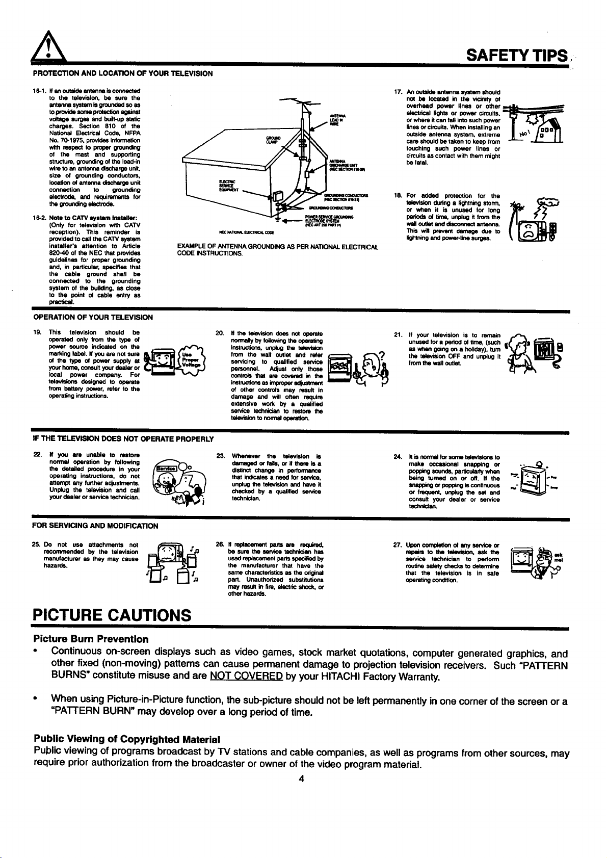
PROTECTION AND LOCATION OF YOUR TELEVISION
16-1. It an outelde antsnne Is connected
to the television, be sure the
antem_ systsm Is grounded so as
toworldssums_ agJnst
voltage surges and built-up static
charges. Section 810 of the
National Electrical Code, NFPA
No. 70-1975, provides information
with r_pect to proper groundng
of the mast and supporting
structure, grounding of the lead-in
wire to an antonrm discharge unit,
size of grounding conductors,
location of antenna discharge unit
connection to grounding
electrode, and requirements for
the groundng alectrode.
16-2. Note to CAW system Installer:
(Only for television with CATV
reception). This reminder is
provided to call the CATV system
Ineteller's attention to Article
820-40 of the NEC that provides
guidelines for proper grounding
and, in particular, specifies that
the cable ground shell be
connected to the grounding
system of the building, as close
to the point of cable entry as
practical.
EXAMPLE OF ANTENNA GROUNDING AS PER NATIONAL ELECTRICAl.
CODE INSTRUCTIONS.
OPERATION OF YOUR TELEVISION
19. This television should be
operated Only from the type of
power source indicated on the . _f"_,
marking label. If you am not sum
of the typa of power supply at
your harm), consult your dealer or
local power company. For
televisions designed to operate
from battery power, refer to the
operating instructions.
-- <1------ sr=c_n==_"_
NEC_1101_L_ C0¢E
20.
It the television Ooas nut operate
homey byfoaow_g_e opera,no
i_ons, unplng the television
from the wall outlet and refer ,_.._.__ _,_._t,,_
servicing to qualified service
personnel. Adjust Only those
controls that ere covered in the
i_ esimm0_rad_m..x
of other controls may result in
damage and will often require
extensive work by a qualified
se_ca t,mchnlcian to restore the
tekwisk>n to nom_ _
(NEC_m'=lmmm_t
SAFETY TIPS
17. An out_=ldeIntanna system shoutd
nof be lucmed in the vicinity ot
eveYneed power lines or other
aluctdcel lights or power circuits,
or where it Can fall into such power T z_
lines or cimults. When installing an II , " _D
outsideantennasystem,ex_rema II _" In I I
care should be taken to keep from _
touching such power lines or
circuits as contact with them might
be fatal.
18. For added protection for the
television qudng a lighming storm, _.. _,_'
or when it is unused for long
periods of time, unplug it from the
well outtst and disconnect antanna.
This will prevent damage due to
lil_'ling and power-line surges.
21. ff your television is to remain ,,._,._ .
unused for s period el time, (such
as when going on a hdiiday), turn
the televi_on OFF and unplug it
from the wag outlet.
IF THE TELEVISION DOES NOT OPERATE PROPERLY
22.
If you are unable to restore
normal operation by following
the detailed procedure in your
operating instructions, do not
attempt any further adjustments.
Unplug the television and call
your dealer or service technician.
Whenever the television is
damaged or felis, or il them is a
distinct change in perfom'Jmce
that indicates a necd for seNice,
unplug the tekwision and have it
chsul_l by a qualltisd se_ca
technidan.
24. It is nom_el fer sume tsie_dons to
make ucc_l snapping or
popping _ounds, par_-'ofady whea
being turned on or off. If the
s_app_g or pepp_g is continuous
er frequent, unplug the s_ and
consult your dealer or service
techdickm.
FOR SERVICING AND MODIFICATION
25. Do not use attachments not
recommended by the television
manufacturer as they may cause
hazards.
J'J'_i 26. It replacemont pans em required. 27. Uponcom_of any service or
be sure the earvica tschnlcion has repalm to Itm television, ask the
used replacement parts _ by service technician to perform
the manufacturer that have the routine se_ checks to determine
same characteristics as the odginel that the television is in safe
part. Unauthorized substitutions oparating condition.
may result in fire, electdc shock, or
other hazards.
PICTURE CAUTIONS
Picture Burn Prevention
• Continuous on-screen displays such as video games, stock market quotations, computer generated graphics, and
other fixed (non-moving) patterns can cause permanent damage to projection television receivers. Such =PATTERN
BURNS" constitute misuse and are _ by your HITACHI Factory Warranty.
• When using Picture-in-Picture function, the sub-pictureshould not be leftpermanently in one corner of the screen or a
=PATTERN BURN" may develop over a long period of time.
Public Viewing of Copyrighted Material
Public viewing of programs broadcast by "IV stations and cable companies, as well as programs from other sources, may
require priorauthorization from the broadcaster or owner of the video program material.
4
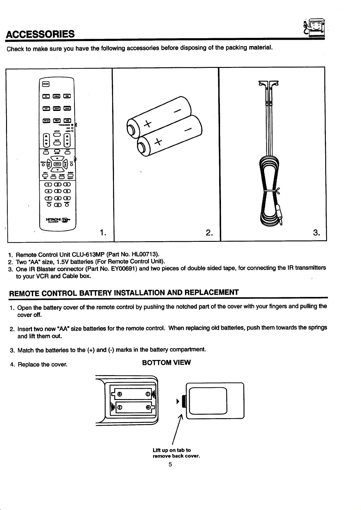
ACCESSORIES
Check to make sure you have the following accessories before disposing of the packing material.
C_3r'_ r_
_e
_0
mO
c5
_cD_
• = m
1. Remote Control Unit CLU-613MP (Part No. HL00713).
2. Two =hA" size, 1.5V batteries (For Remote Control Unit).
3. One IR Blaster connector (Part No. EY00691) and two pieces of double sided tape, for connecting the IR transmitters
to your VCR and Cable box.
REMOTE CONTROL BATTERY INSTALLATION AND REPLACEMENT
1. Open the battery cover of the remote controlby pushingthe notched part of the cover with your fingersand pullingthe
cover off.
2. Insert two new "AA_ size batteries for the remote control. When replacingold batteries, push them towardsthe springs
and liftthem out.
3. Match the batteries to the (+) and (-) marks in the battery compartment.
4. Replace the cover. BOTTOM VIEW
Lift up on tab to
remove back cover.
HOW TO SET UP YOUR NEW HITACHI PROJECTION TV
ANTENNA
Unless your TV is connected to a cable TV system or to a centralized antenna system, a good outdoor color TV antenna is
recommended for best performance. However, ifyou are located in an exceptionally good signal area that is free from interference and
multiple image ghosts, an indoor antenna may be sufficient.
LOCATION
Select an area where sunlight or bright indoor illumination will not fall directly on the picture screen. Also, be sure that the location
selected allows a free flow of air to and from the perforated beck cover of the set.
To avoid cabinet warping, cabinet color changes, and increased chance of set failure, do not place the TV where temperatures can
become excessively hot, for example, in direct sunlight or near a heating appliance, etc.
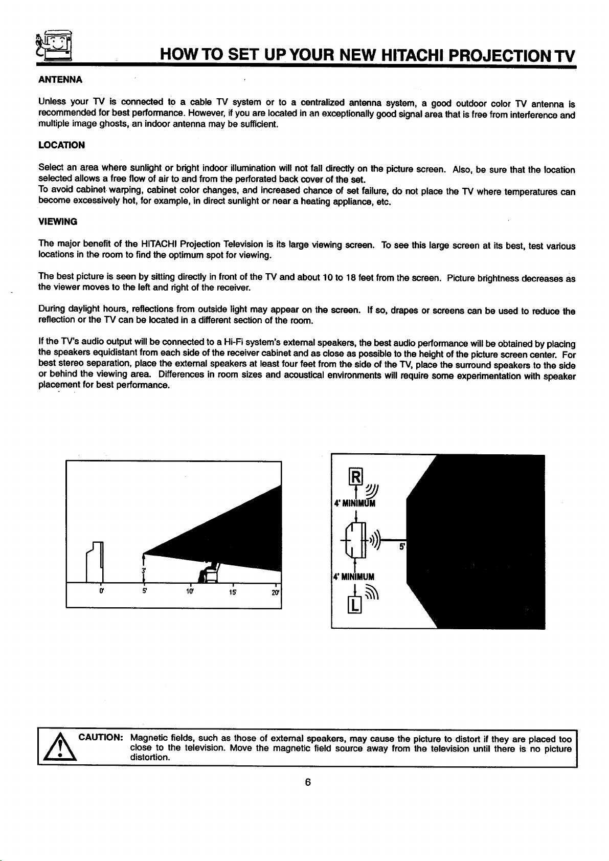
VIEWING
The major benefit of the HITACHI Projection Television is its large viewing screen. To see this large screen at its best, test various
locations in the room to find the optimum spot for viewing.
The best picture is seen by sitting directly in front of the TV and about 10 to 18 feet from the screen. Picture brightness decreases as
the viewer moves to the left and rightof the receiver.
During daylight hours, reflections from outside light may appear on the screen. If so, drapes or screens can be used to reduce the
reflection or the TV can be located in a different section of the room.
Ifthe TV's audio output will be connected to a Hi-Fi system's extemal speakers, the best audio performance will be obtained by placing
the speakers equidistant from each side of the receiver cabinet and as close as possible to the height ofthe picture screen center. For
best stereo separation, place the extemal speakers at least four feet from the side of the TV, place the surround speakers to the side
or behind the viewing area. Differences in room sizes and acoustical environments will require some experimentation with speaker
placement for best performance.
CAUTION:
4' MINIMUM
4' NIMUM
Magnetic fields, such as those of extemal speakers, may cause the picture to distort if they are placed too
close to the television. Move the magnetic field source away from the television until there is no picture
distortion.
6
I
HOOK-UP CABLES AND CONNECTORS
II
Most video/audio connections between components can be made with shielded video and audio cables that have phono connectors.
For best performance, video cables should use 75-Ohm coaxial shielded wire. Cables can be pumhased from most stores that sell
audio/video products. Below are illustrationsand names of common connectors. Before purchasing any cables, be sure of the output
and input connector types required by the various components and the length of each cable.
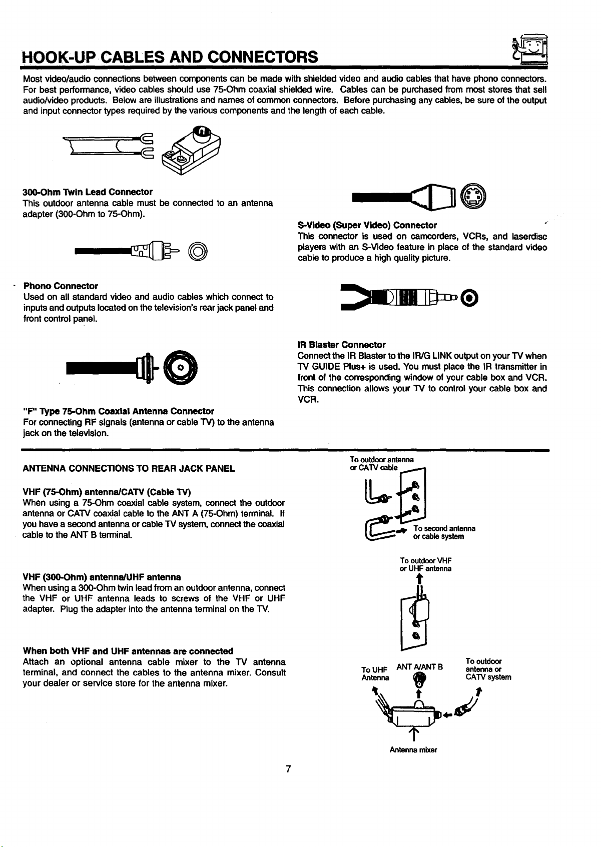
300-Ohm Twin Lead Connector
This outdoor antenna cable must be connected to an antenna
adapter (300-Ohm to 75-Ohm).
S-Video (Super Video) Connector "_
This connector is used on camcorders, VCRs, and laserdisc
players with an S-Video feature in place of the standard video
cable to produce a high quality picture.
Phono Connector
Used on all standard video and audio cables which connect to
inputs and outputs located on the television's rear jack panel and
front control panel.
IR Blaster Connector
Connect the IR Blaster to the IR/G LINK output on your TV when
O
"F" Type 75-Ohm Coaxial Antenna Connector
For connecting RF signals (antenna or cable TV) to the antenna
jack on the television.
TV GUIDE Plus+ is used. You must place the IR transmitter in
front of the corresponding window of your cable box and VCR.
This connection allows your TV to control your cable box and
VCR.
ANTENNA CONNECTIONS TO REAR JACK PANEL
VHF (75-Ohm) antenna/CAW (Cable TV)
When using a 75-Ohm coaxial cable system, connect the outdoor
antenna or CATV coaxial cable to the ANT A (75-Ohm) terminal, if
you have a second antenna or cable TV system, connect the coaxial
cable to the ANT B terminal.
VHF (300-Ohm) antenna/UHF antenna
When using a 300-Ohm twin lead from an outdoorantenna, connect
the VHF or UHF antenna leads to screws of the VHF or UHF
adapter. Plug the adapter into the antenna terminal on the TV.
When both VHF and UHF antennae are connected
Attach an optional antenna cable mixer to the TV antenna
terminal, and connect the cables to the antenna mixer. Consult
your dealer or service store for the antenna mixer.
Tooutdoorantenna
orCATVcable
_lp Tor%bSeCl_sndy_tnJmeenna
To outdoorVHF
or UHF antenna
ToUHF ANTA/ANTB antennaor
Antenna (_1 CATVsystem
Antenna mixer
Tooutdoor
7
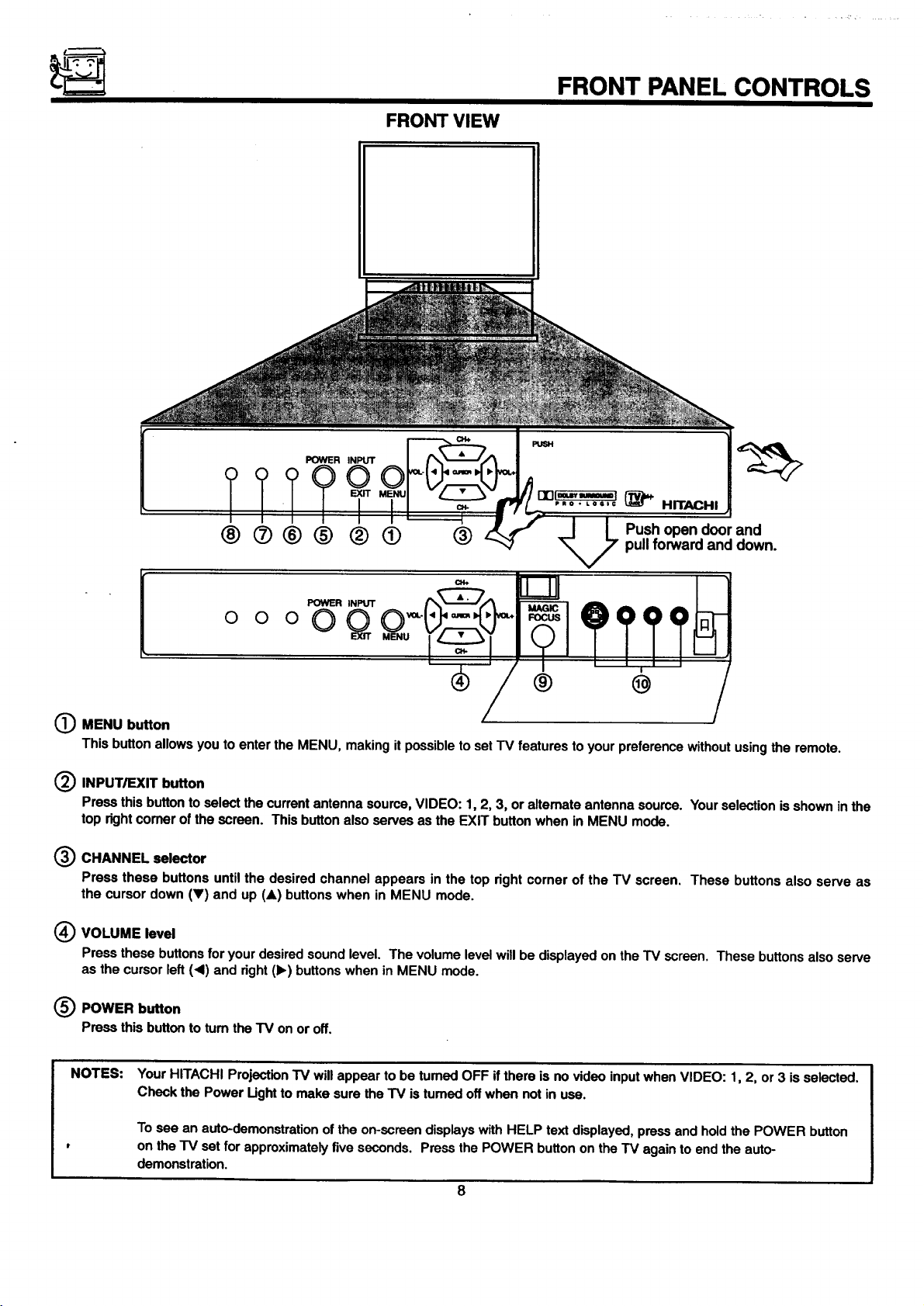
FRONT VIEW
FRONT PANEL CONTROLS
POWER INPUT
°°°OQ
® @
(_ MENU button
This button allows you to enter the MENU, making it possible to set "IV features to your preference without using the remote.
(_ INPUT/EXIT button
Press this button to select the current antenna source, VIDEO: 1, 2, 3, or altemate antenna source. Your selection is shown in the
top rightcomer of the screen. This button also serves as the EXIT button when in MENU mode.
(_) CHANNEL selector
Press these buttons until the desired channel appears in the top right corner of the TV screen. These buttons also serve as
the cursor down (V) and up (A) buttons when in MENU mode.
(_ VOLUME level
Press these buttons for your desired sound level. The volume level will be displayed on the TV screen. These buttons also serve
as the cursor left (.d) and right (1_)buttons when in MENU mode.
(_) POWER button
Pressthisbuttonto tumtheTV onoroff.
NOTES:
Your HITACHI Projection TV will appear to be turned OFF if there is no video input when VIDEO: 1, 2, or 3 is selected.
Check the Power Ught to make sure the TV is tumed off when not in use.
To see an auto-demonstration of the on-screen displays with HELP text displayed, press and hold the POWER button
on the TV set for approximately five seconds. Press the POWER button on the TV again to end the auto-
demonstration.
8
FRONT PANEL CONTROLS
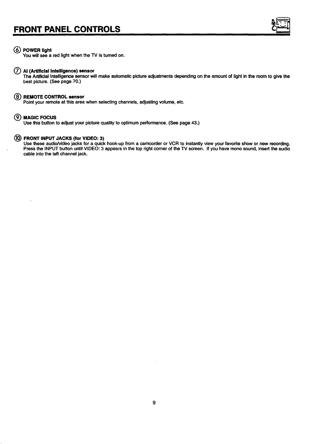
(_ POWER light
You will see a red light when the TV is tumed on.
O AI (Artificial Intelligence) sensor
The Artificial Intelligence sensor will make automatic picture adjustments depending on the amount of lightin the room to give the
best picture. (See page 70.)
(_) REMOTE CONTROL sensor
Pointyourremoteat thisareawhenselectingchannels,adjustingvolume,etc.
(_) MAGIC FOCUS
Use this button to adjust your picture quality to optimum performance. (See page 43.)
1(_ FRONT INPUT JACKS (for VIDEO: 3)
Use these audio/video jacks for a quick hook-up from a camcorder or VCR to instantly view your favorite show or new recording.
Press the INPUT button until VIDEO: 3 appears in the top rightcorner of the "iV screen. If you have mono sound, insert the audio
cable into the left channel jack.
FRONT PANEL JACKS AND CONNECTIONS
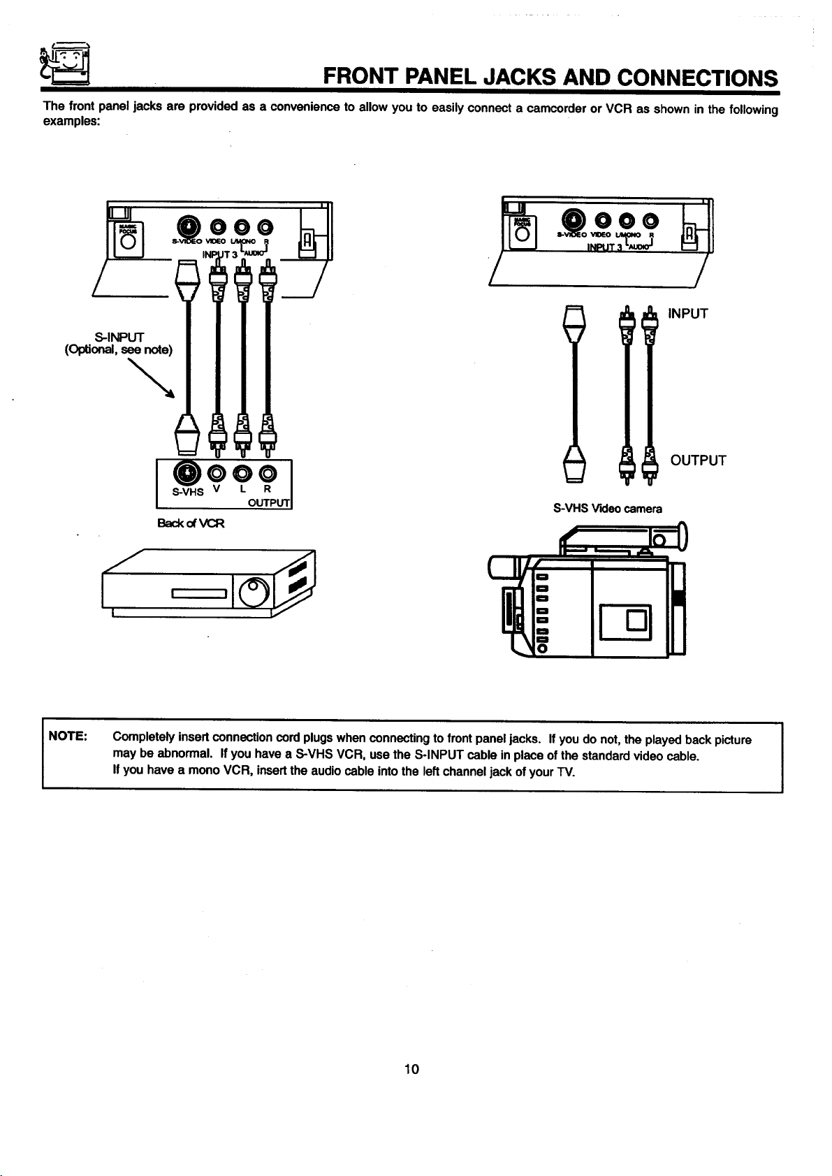
The front panel jacks are provided as a convenience to allow you to easily connect a camcorder or VCR as shown in the following
examples:
/
INPUT
S-INPUT
(Optional, see note)
OUTPUT
NOTE:
S-VHS Videocamera
Back of VCR
Completely insert connection cord plugs when connecting tofront panel jacks. If you do not, the played back picture
may be abnormal. If you have a S-VHS VCR, use the S-INPUT cable in place of the standard video cable.
If you have a mono VCR, insertthe audio cable into the left channel jack of your TV.
10
REAR PANEL JACKS
r
O
REARSPE/W,ER ANTA
O
eQ ONLY
O0
TC(_NVERTER
L
O"
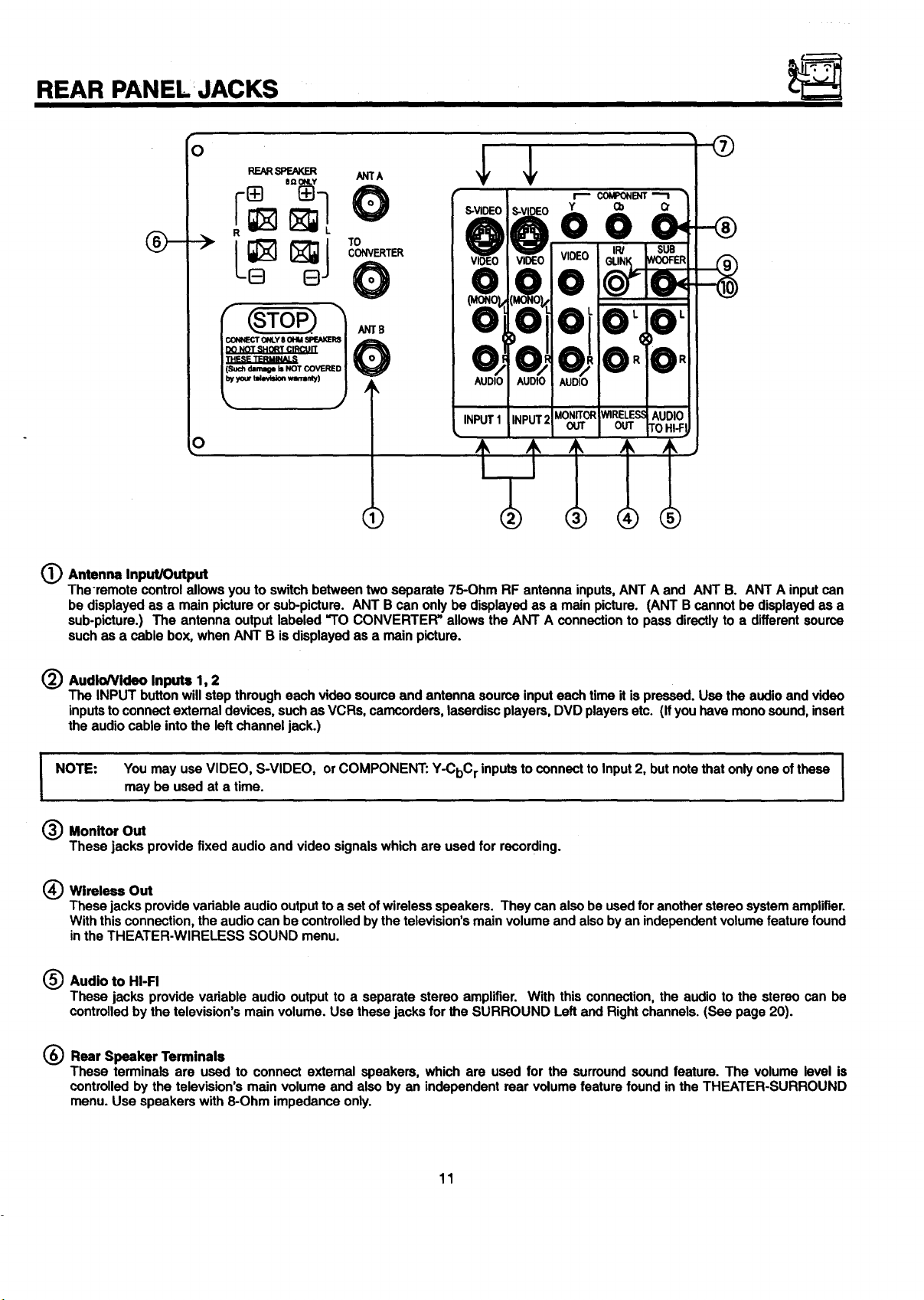
_) Antenna Input/Output
The-remote control allows you to switch between two separate 75-Ohm RF antenna inputs, ANT A and ANT B. ANT A input can
be displayed as a main picture or sub-picture. ANT B can only be displayed as a main picture. (ANT B cannot be displayed as a
sub-picture.) The antenna output labeled "TO CONVERTER" allows the ANT A connection to pass directly to a different source
such as a cable box, when ANT B is displayed as a main picture.
(_) AudioNideo Inputs 1, 2
The INPUT button will step through each video source and antenna source input each time it is pressed. Use the audio and video
inputsto connect extemal devices, such as VCRs, camcorders, laserdisc players, DVD players etc. (Ifyou have mono sound, insert
the audio cable into the left channel jack.)
You may use VIDEO, S-VIDEO, orCOMPONENT: Y-CbC r inputs to connect to Input 2, but note that only one of these I
I NOTE:
_ Monitor Out
These jacks provide fixed audio and video signals which are used for recording.
(_ Wireless Out
These jacks provide vadable audio output to a setof wireless speakers. They can also be used for another stereo system amplifier.
With this connection, the audio can be controlled by the television's main volume and also by an independent volume feature found
inthe THEATER-WIRELESS SOUND menu.
(_ Audio to HI-FI
These jacks provide variable audio output to a separate stereo amplifier. With this connection, the audio to the stereo can be
controlled by the television's main volume. Use these jacks for the SURROUND Left and Right channels. (See page 20).
may be used at a time.
I
I
(_) Rear Speaker Terminals
These terminals are used to connect external speakers, which are used for the surround sound feature. The volume level is
controlled by the television's main volume and also by an independent rear volume feature found in the THEATER-SURROUND
menu. Use speakers with 8-Ohm impedance only.
11
FIRST TIME USE
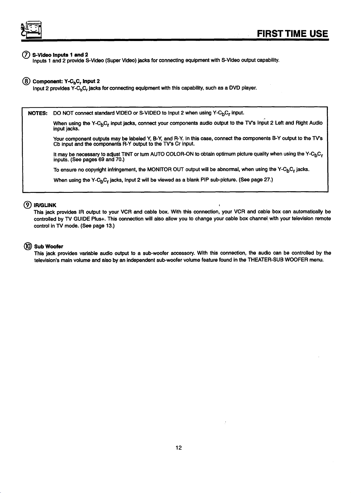
S-Video Inputs 1 and 2
Inputs 1 and 2 provide S-Video (Super Video) jacks for connecting equipment with S-Video output capability.
Component: Y-CbC r Input 2
Input 2 provides Y-CbC rjacks for connecting equipment with this capability, such as a DVD player.
NOTES:
IR/GLINK
This jack provides IR output to your VCR and cable box. With this connection, your VCR and cable box can automatically be
controlled by TV GUIDE Plus+. This connection will also allow you to change your cable box channel with your television remote
control in TV mode. (See page 13.)
@ Sub Woofer
This jack provides variable audio output to a sub-woofer accessory. With this connection, the audio can be controlled by the
television's main volume and also by an independent sub-woofer volume feature found in the THEATER-SUB WOOFER menu.
DO NOT connect standard VIDEO or S-VIDEO to Input 2 when using Y-CbCr input.
When using the Y-CbC r inputjacks, connect your components audio output to the TV's Input 2 Left and Right Audio
input jacks.
Your component outputs may be labeled Y, B-Y, and R-Y. In this case, connect the components B-Y output to the TV's
Cb input and the components R-Y output to the TV's Cr input.
It may be necessary to adjust TINT or tum AUTO COLOR-ON to obtain optimum picture quality when using the Y-CbC r
inputs. (See pages 69 and 70.)
To ensure no copyright infringement,the MONITOR OUT output will be abnormal, when using the Y-CbC r jacks.
When using the Y-CbC rjacks, Input2 will be viewed as a blank PIP sub-picture. (See page 27.)
12
REAR PANEL CONNECTIONS
Cable"iVBox VCR#1
TOIRJGLINK----_
01
OutsideAmnm
DVDPlayer,
Laseediscplayer,etc+
SubWoofer
L©l
Sub
Woofer
LAudio
R
"+.61
&o I
+I
_]_1
-cOt
Ioo oolooI
,(,-+,.-+p+
VCR #2
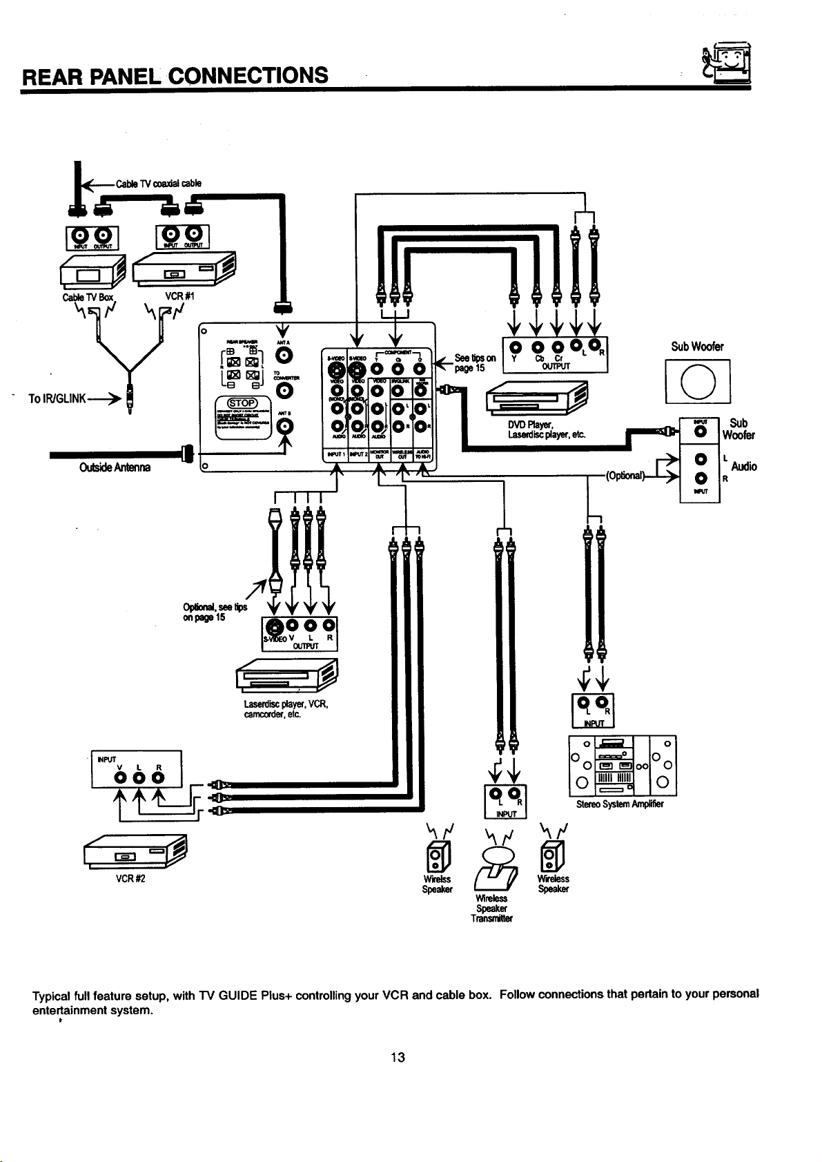
Typical full feature setup, with TV GUIDE Plus+ controllingyour VCR and cable box. Follow connections that pertain to your personal
ente_ainment system.
W'_Iss W'reless
Speaker Speaker
13
Wireless
Speaker
Transrdtt_
REAR SPEAKER TERMINAL CONNECTIONS
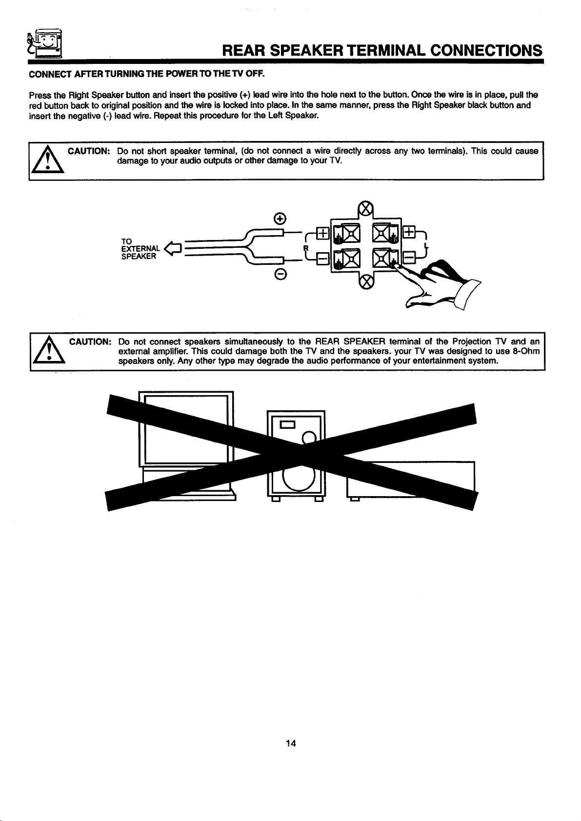
CONNECT AFTER TURNING THE POWER TO THE TV OFF.
Press the Right Speaker button and insert the positive (+) lead wire into the hole next to the button. Once the wire is in place, pull the
red button back to original position and the wire is locked into place. In the same manner, press the Right Speaker black button and
insert the negative (-) lead wire. Repeat this procedure for the Left Speaker.
I±
CAUTION:
CAUTION:
Do notshortspeakerterminal,(do not connecta wire directlyacrossany two terminals).This couldcause
damagetoyouraudiooutputsorotherdamagetoyourTV.
TO
EXTERNAL ,_
SPEAKER
®
Do not connect speakers simultaneously to the REAR SPEAKER terminal of the Projection TV and an
external amplifier. This could damage both the TV and the speakers, your TV was designed to use 8-Ohm
speakers only. Any other type may degrade the audio performance of your entertainment system.
I
14
TIPS ON REAR PANEL CONNECTIONS
TIPS ON REAR PANEL CONNECTIONS
S-Video connections are provided for high performance laserdisc players, VCRs etc. that have this feature. Use these connections
in place of the standard video connection if your device has this feature.
If your device has only one audio output (mono sound), connect it to the left audio jack on the television.
Refer to the operating guide of your other electronic equipment for additional information on connecting your hook-up cables.
Youmayuse VIDEO, S-VIDEO, orCOMPONENT:Y-CbCr inputsto connectto Input2, butnotethat onlyoneofthesemaybe used
at a time.
Connect only 1 component to each input jack.
COMPONENT: Y-CbC r connections are provided for high performance components, such as DVD players. Use these connections
in place of the standard video connection if your device has this feature.
When using the Y-CbC r input jacks, connect your components audio output to the TV's Input 2 Left and Right Audio input jacks.
Your component outputs may be labeled Y, B-Y, and R-Y. In this case, connect the components B-Y output to the TV's Cb input
and the components R-Y output to the TV's Cr input.
It may be necessary to adjust TINT or tum AUTO COLOR-ON to obtain optimum picture quality when using the Y-CbC r inputs.
(See pages 69 and 70.)
To ensure no copyright inffingement, the MONITOR OUT outputwill be abnormal, when using the Y-CbC rjacks.
When using the Y-CbC r jacks, Input 2 will be viewed as a blank PIP sub-picture. (See page 24.)
When using the IR Blaster Connector, make sure only 1 IR transmitter (the connector has 2) is used for each component. If you
wish to control only your VCR with the IR/GLINK output of your TV, be sure only 1 IR transmitter is used or else erratic VCR
operation may occur.
If you need to use only 1 IR transmitter,simplyplace the secondIR transmitterbehind the TV. Do NOT cut offthe secondIR
transmitter.
TV GUIDE Plus+ requires that you make connections in a specific way. The signal you wish to use with TV GUIDE Plus+ must be
connected to the ANT A input on your TV. (See page 13.)
15
EXTERNAL CONNECTIONS
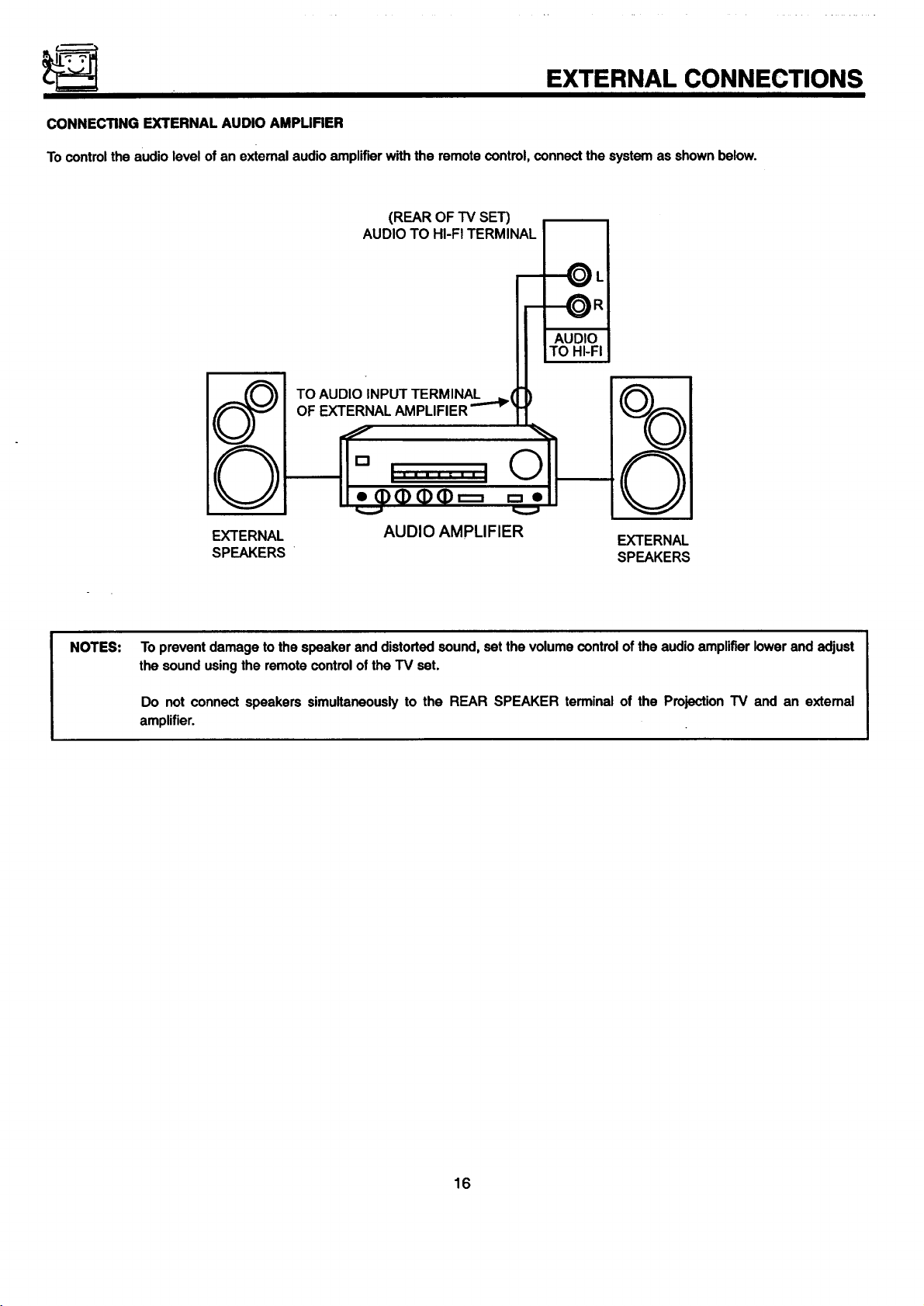
CONNECTING EXTERNAL AUDIO AMPUFIER
To control the audio level of an external audio amplifier with the remote control, connect the system as shown below.
(REAROFTV SET)
AUDIO TO HI-FITERMINAL
_L
I AUDIO
LTO HI-FI
8°
NOTES:
EXTERNAL
SPEAKERS
To prevent damage to the speaker and distorted sound, set the volume control of the audio amplifier lower and adjust
the sound using the remote control of the TV set.
Do not connect speakers simultaneously to the REAR SPEAKER terminal of the Projection TV and an extemal
amplifier.
AUDIO AMPLIFIER
EXTERNAL
SPEAKERS
16
CONNECTING EXTERNAL VIDEO SOURCES
The exact arrangement you use to connect the VCR, camcorder, laserdisc player, and DVD player to your TV set is dependent on the
model and features of each component. Check the owner's manual of each component for the location of video and audio inputs and
outputs.
The followingconnectiondiagramsareofferedassuggestions.However,youmayneedtomodifythemtoaccommodateyourparticular
assortmentof componentsand features. Forbestperformance,videoand audiocablesshouldbemadefrom coaxial shieldedwire.
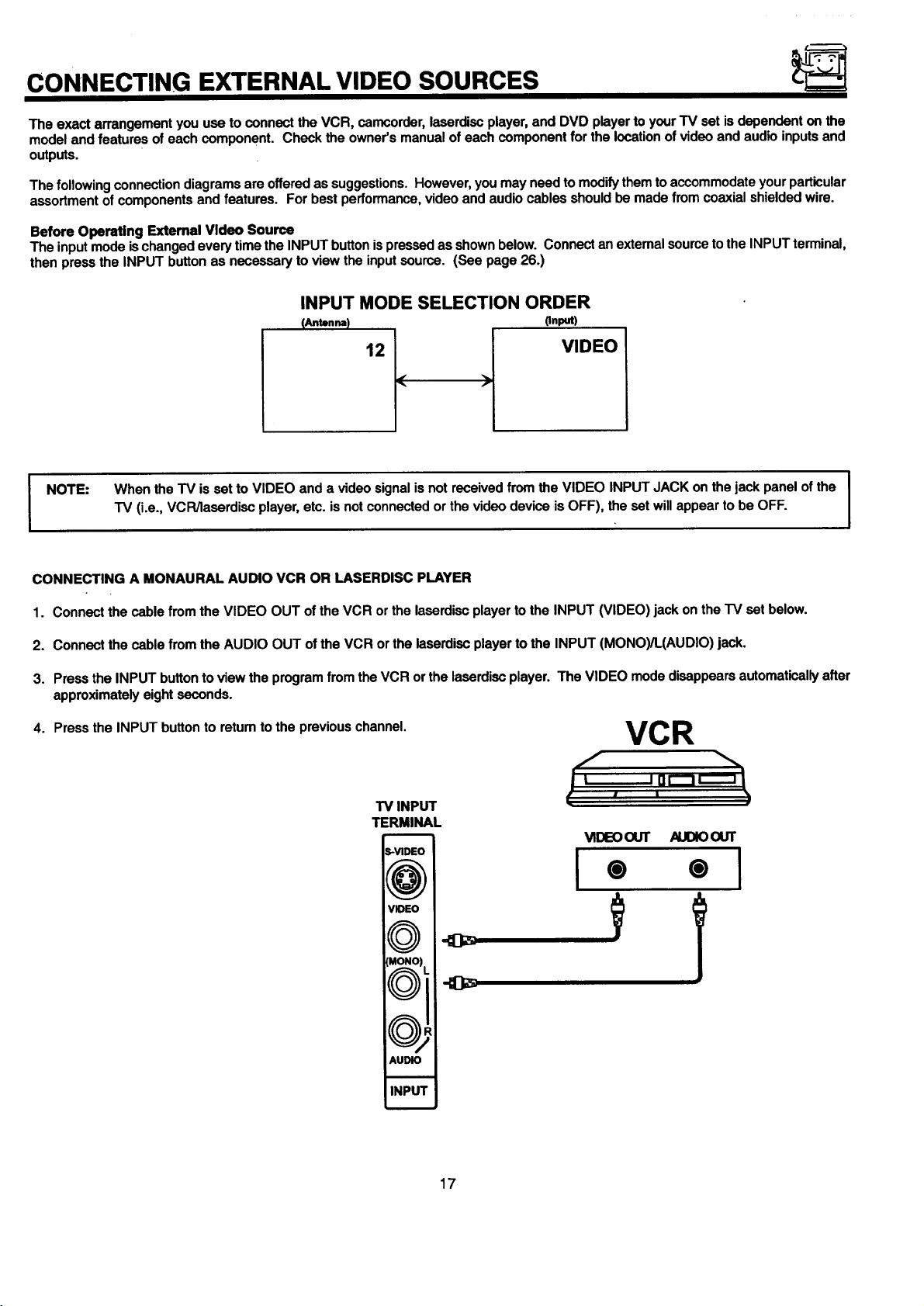
Before Operating External Video Source
The input mode ischanged every time the INPUT button ispressed as shown below. Connect an external source to the INPUT terminal,
then press the INPUT button as necessary to view the input source. (See page 26.)
INPUT MODE SELECTION ORDER
pnput)
VIDEO
When the TV is set to VIDEO and a video signal is not received from the VIDEO INPUT JACK on the jack panel of the I
I NOTE:
"IV (i.e., VCR/laserdiso player, etc. is not connected or the video device is OFF), the set will appear to be OFF.
I
I
CONNECTING A MONAURAL AUDIO VCR OR LASERDISC PLAYER
1. Connect the cable from the VIDEO OUT of the VCR or the laserdisc player to the INPUT (VIDEO) jack on the "IV set below.
2. Connect the cable from the AUDIO OUT of the VCR or the laserdisc player to the INPUT (MONO)/L(AUDIO) jack.
3. Press the INPUT button toview the program from the VCR or the laserdisc player. The VIDEO mode disappears automatically after
approximately eight seconds.
4. Press the INPUT button to retum to the previous channel.
VCR
,F ,n,,,
TV INPUT
TERMINAL
m
_-VIDEO
I
o '; i
AUDIO
INPU'I'
17
CONNECTING EXTERNAL VIDEO SOURCES
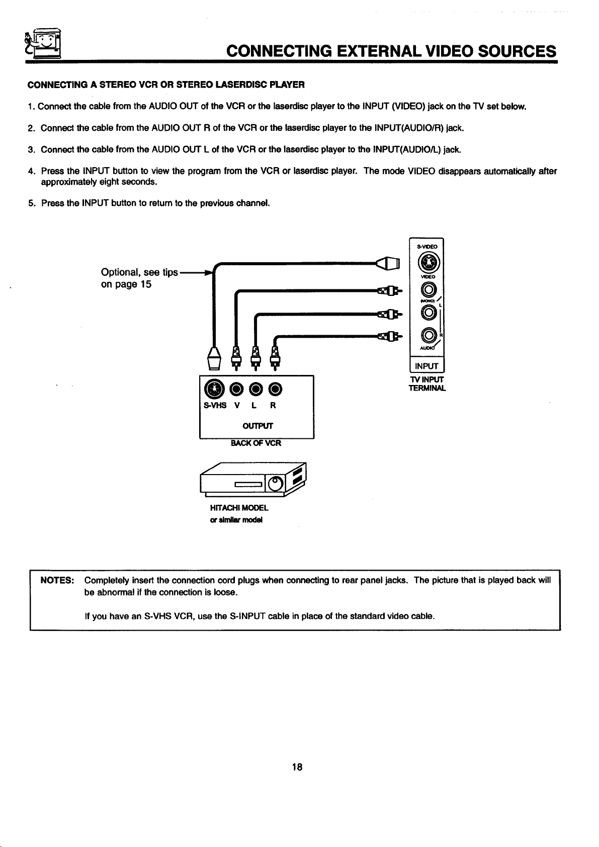
CONNECTING A STEREO VCR OR STEREO LASERDISC PLAYER
1. Connect the cable from the AUDIO OUT of the VCR or the laserdisc player to the INPUT (VIDEO) jack on the TV set below.
2. Connect the cable from the AUDIO OUT R of the VCR or the laserdisc player to the INPUT(AUDIO/R) jack.
3. Connect the cable from the AUDIO OUT L of the VCR or the laserdisc player to the INPUT(AUDIO/L) jack.
4. Press the INPUT button to view the program from the VCR or laserdisc player. The mode VIDEO disappears automatically after
approximately eight seconds.
5. Press the INPUT button to return to the previous channel.
S-WDEO
Optional, see tips-_P
on page 15
NOTES:
u
"IVINPUT
0000
S-VI-IS V L R
OUTPUT
BACKOFVCR
I
HITACHIMODEL
orsimilarmodel
Completely insert the connection cord plugs when connecting to rear panel jacks. The picture that is played back will
be abnormal if the connection is loose.
If you have an S-VHS VCR, use the S-INPUT cable in place of the standard video cable.
TERMINAL
18
CONNECTING EXTERNAL VIDEO SOURCES
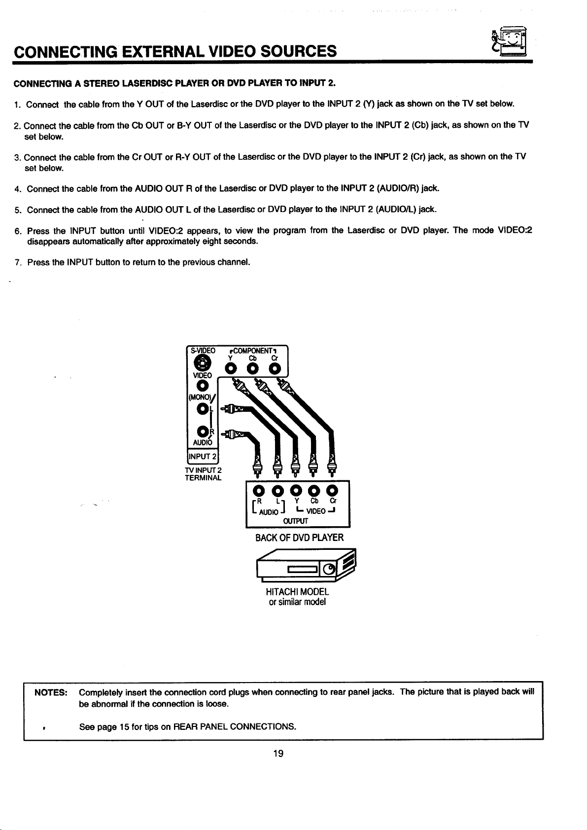
CONNECTING A STEREO LASERDISC PLAYER OR DVD PLAYER TO INPUT 2.
1. Connect the cable from the Y OUT of the Laserdisc or the DVD player to the INPUT 2 {Y) jack as shown on the TV set below.
2. Connect the cable from the Cb OUT or B-Y OUT of the Laserdisc or the DVD player to the INPUT 2 (Cb) jack, as shown on the TV
set below.
3. Connect the cable from the Cr OUT or R-Y OUT of the Laserdisc or the DVD player to the INPUT 2 (Cr) jack, as shown on the TV
set below.
4. Connect the cable from the AUDIO OUT R of the Laserdisc or DVD player to the INPUT 2 (AUDIO/R) jack.
5. Connect the cable from the AUDIO OUT L of the Laserdisc or DVD player to the INPUT 2 (AUDIO/L) jack.
6. Press the INPUT button until VIDEO:2 appears, to view the program from the Laserdisc or DVD player. The mode VIDEO:2
disappears automatically after approximately eight seconds.
7. Press the INPUT button to return to the previous channel.
S-VIDEO rCOMPONENTI
Y Cb Cr
000
"iVINPUT2
TERMINAL
OOOOO
[ AUDIO"1 I- VIDEOJ
R L Y Cb Cr
OUTPUT
BACKOFDVDPLAYER
HITACHIMODEL
or similarmodel
NOTES:
Completely insert the connection cord plugs when connecting to rear panel jacks. The picture that is played back will
be abnormal if the connection is loose.
See page 15 for tips on REAR PANEL CONNECTIONS.
19
AUDIO SYSTEM .SETUP
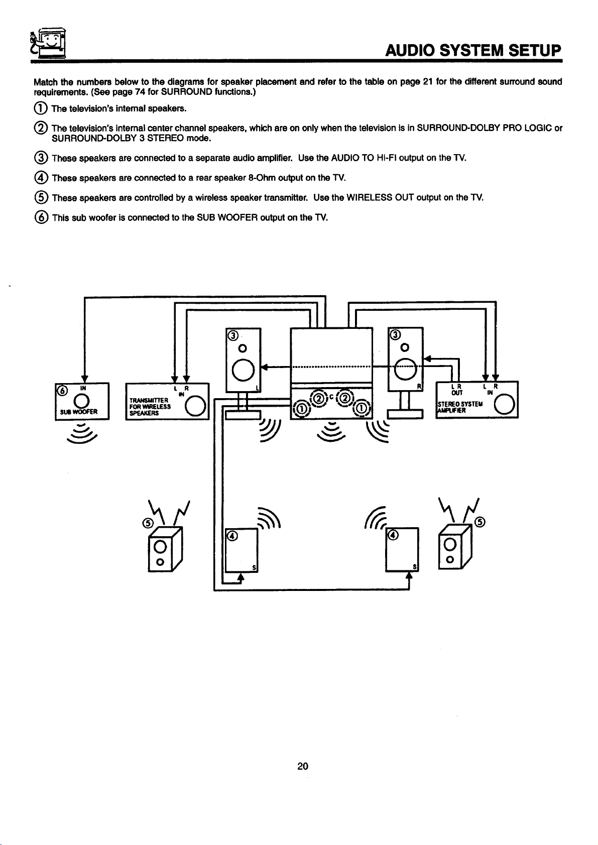
Match the numbers below to the diagrams for speaker placement and refer to the table on page 21 for the different surround sound
requirements. (See page 74 for SURROUND functions.)
(_The television's intemal speakers.
(_) The television's intemal center channel speakers, which are on only when the television is in SURROUND-DOLBY PRO LOGIC or
SURROUND-DOLBY 3 STEREO mode.
t_) These speakers are connected to a separate audio amplifier. Use the AUDIO TO HI-FI output on the TV.
(_ These speakers are connected to a rear speaker 8-Ohm output on the TV.
(_ These speakers are controlled by a wireless speaker transmitter. Use the WIRELESS OUT output on the TV.
(_) This sub woofer is connected to the SUB WOOFER output on the TV.
IN
2O
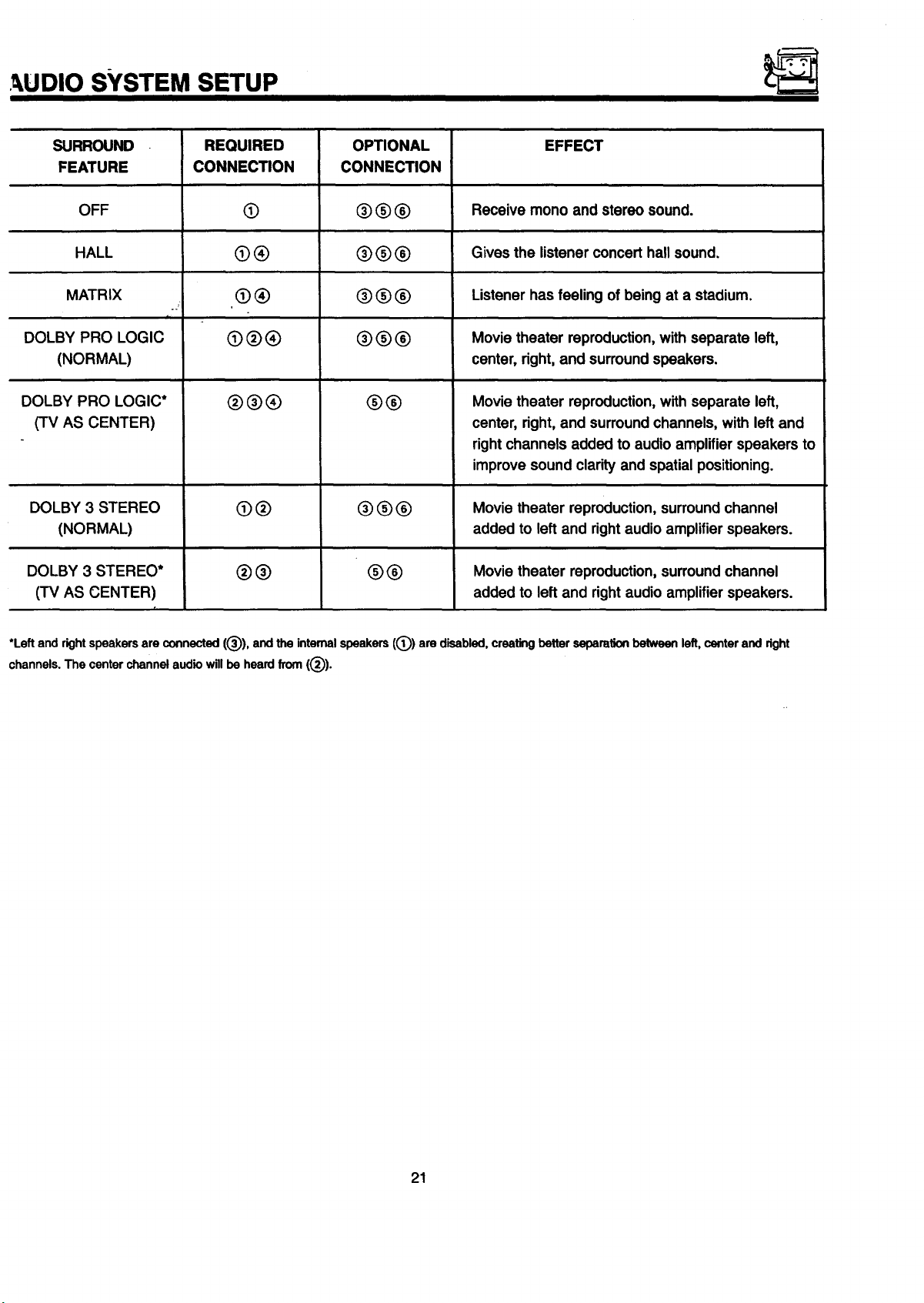
,_UDIO SYSTEM SETUP
SURROUND
FEATURE
OFF
HALL
MATRIX
DOLBY PRO LOGIC
(NORMAL)
DOLBY PRO LOGIC*
(TV AS CENTER)
DOLBY 3 STEREO
(NORMAL)
DOLBY 3 STEREO*
(TV AS CENTER)
REQUIRED
CONNECTION
@
@®
®®
@®®
®®®
@®
®®
OPTIONAL
CONNECTION
®®0
®O®
®OO
®00
0®
®®®
00
EFFECT
Receive mono and stereo sound.
Gives the listener concert hall sound.
Listener has feeling of being at a stadium.
Movie theater reproduction,with separate left,
center, right,and surroundspeakers.
Movie theater reproduction,with separate left,
center, right, and surround channels, with left and
right channels added to audio amplifier speakers to
improve sound clarity and spatial positioning.
Movie theater reproduction,surround channel
added to left and right audio amplifier speakers.
Movie theater reproduction, surround channel
added to left and right audio amplifier speakers.
*Leftand rightspeakersare connected(®), andthe internalspeakers((_) are disabled,creatingbetterseparationbetweenleft,centerand right
channels.The centerchannelaudiowillbe heardfrom (®).
21

THE GENIUS REMOTE CONTROL (CLU-613MP)
In additionto controllingall the functions on your HITACHI
ProjectionTV, theremotecontrolisdesignedtooperatedifferent
typesofVCRs, CATV(cableTV)/satelliteconverters,andaudio
equipmentwithone touch. Basicoperationkeysare grouped
togetherinonearea. All othercontrols areseparatedfrom them
and arrangedin MULTI-PAGEsections,witha displaythat can
be switchedto cover any of the three pages. Functionsare
arranged and propedy categorized into windows, making
operationsimplewhenmultiplefunctionsaretobe controlled.
To operate your TV, slide the MULTI-PAGE select switch on the
side of the remote to TV/CABLE/DSS mode. Press the TV button
and the remote will now control your television.
To operate your cable box, slide the MULTI-PAGE select switch
on the side of the remote to TV/CABLE/DSS mode. Press the
CABLE button and the remote will now control your cable box.
(See page 31 for instructions on how to program the remote to
control your cable box.)
To operate your satellite box, slide the MULTI-PAGE select
switch on the side of the remote to TV/CABLE/DSS mode. Press
the DSS buttonand the remote will now control your satellite box.
(See page 31 for instructions on how to program the remote to
control your satellite box.)
Tooperate your VCR, slide the MULTI-PAGE select switchon the
side of the remote to VCR mode. The remote will now control
your VCR. (See page 30 for instructionson how to program the
remote to control your VCR.)
To operate your audio equipment, slide the MULTI-PAGE select
switch on the side of the remote to AUDIO mode. Press the
button which corresponds to the component you would like to
control (AMP, CD, TAPE). The remote will now control your audio
equipment. (See page 32 for instructionson how to program the
remote to control your audio equipment.)
(_ MULTI-PAGE select switch
This selects the button layout of the multi-page section of
the remote control.
TV/CABLE/OSS •
INPUT SLEEP
0 0
VCR O
(i)
Auolo O
®
(_) MULTI-PAGE buttons
These buttons change functions as shown on page 23.
(_) LIGHT button
When you are in a dark room, press this button on the side
of the remote to light up the buttons shown in _). The light
will stay on for about eight seconds if the lightbutton is not
pressed again. These buttons will not appear to light ifthe
room is tee bright.
22
HITACHI
CI-U-613MP
J
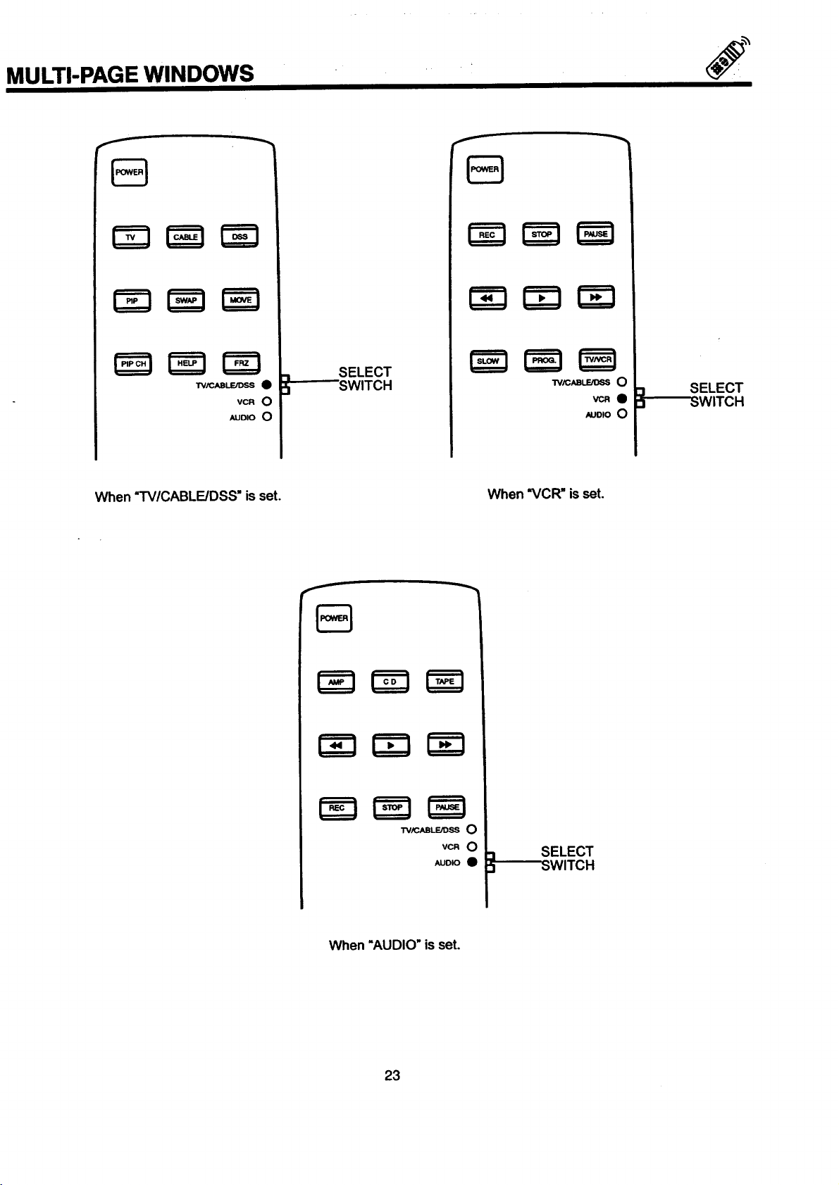
MULTI-PAGE WINDOWS
SELECT
_"-'--SWITCH
VCR 0
AUDIO 0
W/CABLE/DSS O
AUDIO O
When "TV/CABLE/DSS" isset. When "VCR" is set
vcRe
3
3
SELECT
SWITCH
TViCABLE/DSS O
VCR O
AUDIO O
When =AUDIO" is set.
23
_I_swITC H
SELECT
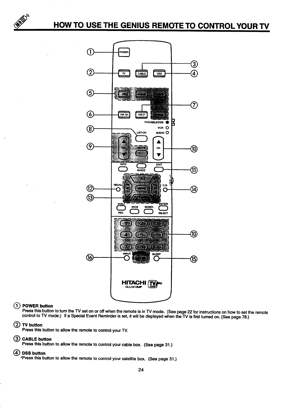
HOW TO USE THE GENIUS REMOTE TO CONTROL YOUR TV
O
®
@
VCRO
*UO_OO
®
INFO (_
®
Q POWER button
Press this buttonto tum the TV set on or off when the remote is in IV mode. (See page 22 for instructionson how toset the remote
control to TV mode.) If a Special Event Reminder is set, it will be displayed when the TV is firsttumed on. (See page 78.)
(_TV button
Press this button to allow the remote to control yourTV.
INPUT
0
GUIDE
CD
®
_) CABLE button
Press this button to allow the remote to control yourcable box. (See page 31.)
(_) DSS button
'Press this button to allow the remote to control your satellite box. (See page 31.)
24
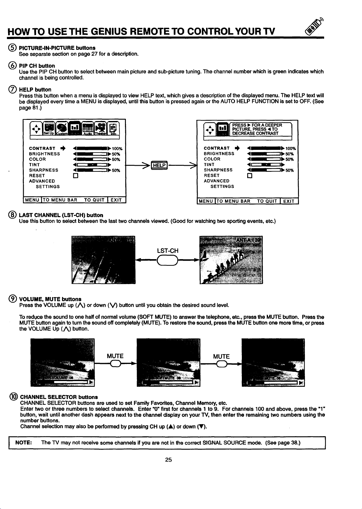
HOW TO USE THE GENIUS REMOTE TO CONTROL YOUR TV
(_ PICTURE-IN-PICTURE buttons
See separate section on page 27 for a description.
(_) PIP CH button
Use the PIP CH button to select between main picture and sub-picture tuning. The channel number which is green indicateswhich
channel is being controlled.
O HELP button
Press this button when a menu is displayed to view HELP text, which gives a description ofthe displayed menu. The HELP text will
be displayed every time a MENU isdisplayed, untilthis button is pressed again or the AUTO HELP FUNCTION isset to OFF. (See
page 81.)
CONTRAST _ 4__" 100%
BRIGHTNESS 4_m_"--1_. 50%
COLOR 4_r_"ll_ 50%
TINT 4 r"_lr_'-t I_
SHARPNESS 4 ml_'_"t_. 50%
RESET []
ADVANCED
SETTINGS
MENU ITO MENU BAR TO QUIT I EXIT
• i,, PICTURE, PRESS < TO
{: 1
CONTRAST ,,), ,qmmslb 100%
BRIGHTNESS <lll_a----"'-I_ 50%
COLOR '___' 50%
TINT 41r-"--_r'_l_
f
SHARPNESS <111_11"_'-I_ ,50%
RESET []
ADVANCED
SETTINGS
_IENU ITOMENU BAR TO QUIT I EXIT
DECREASECONTRAST
LAST CHANNEL (LST-CH) button
Use this button to select between the last two channels viewed. (Good for watching two sporting events, etc.)
LST-CH
(_ VOLUME, MUTE buttons
Press the VOLUME up (/_) or down (V) button until you obtain the desired sound level.
To reduce the sound to one half of normal volume (SOFT MUTE) to answer the telephone, etc., press the MUTE button. Press the
MUTE button again to turn the sound off completely (MUTE). To restore the sound, press the MUTE button one more time, or preSS
the VOLUME Up (/_) button.
MUTE MUTE
(_) CHANNEL SELECTOR buttons
CHANNEL SELECTOR buttons are used to set Family Favorites, Channel Memory, etc.
Enter two or three numbers to select channels. Enter '1)"first for channels 1 to 9. For channels 100 and above, press the "1"
button, wait until another dash appears next to the channel display on your TV, then enter the remaining two numbers using the
number buttons.
Channel selection may also be performed by pressing CH up (&) or down (V).
I NOTE: The "IV may not receive some channels if you are not in the correct SIGNAL SOURCE mode. (See page 38.) I
25
HOW TO USE THE REMOTE TO CONTROL YOUR TV
(_) Exrr button
When in MENU mode, this button will exit all On-Screen Displays.
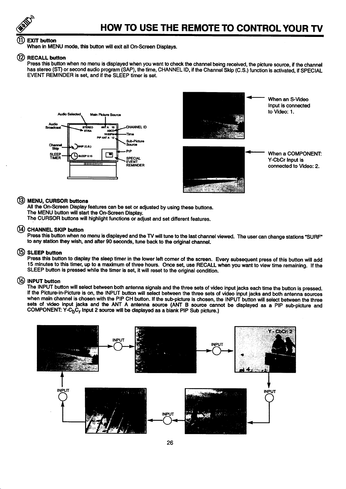
(_) RECALL button
Press this buttonwhen no menu is displayed when you want to check the channel being received, the picture source, ifthe channel
has stereo (ST) or second audio program (SAP), the time, CHANNEL ID, ifthe Channel Skip (C.S.) function isactivated, if SPECIAL
EVENT REMINDER is set, and if the SLEEP timer is set.
When an S-Video
Inputis connected
AudloSelected,, Main_ So,me
Audio _
SO:_PM< _Time
PIP ANTA 12
Channd ,._.._P ,c.L) _Source
sup m
SLEEP _ '(_SI.BEP O:.lS _. _PIP
TIMER _ SPECIAL
IIIIIIIIF|_I _ EVENT
Sub-Picture
REMINDER
to Video: 1.
When a COMPONENT:
Y-CbCr Input is
connected to Video: 2.
(_) MENU, CURSOR buttons
All the On-Screen Display features can be set or adjusted by using these buttons.
The MENU button will start the On-Screen Display.
The CURSOR buttons will highlightfunctions or adjust and set different features.
@ CHANNEL SKIP button
Press this buttonwhen no menu is displayed and the TV will tune to the last channel viewed. The user can change stations "SURF"
to any station they wish, and after 90 seconds, tune back to the original channel.
(_ SLEEP button
Press this button to display the sleep timer in the lower left comer of the screen. Every subsequent press of this button will add
15 minutes to this timer, up to a maximum of three hours. Once set, use RECALL when you want to view time remaining. If the
SLEEP button is pressed while the timer is set, it will reset to the original condition.
INPUT button
The INPUT buttonwill select between both antenna signalsand the three sets of video input jacks each time the button is pressed.
If the Picture-in-Picture is on, the INPUT button will select between the three sets of video input jacks and both antenna sources
when main channel is chosen with the PIP CH button. If the sub-picture is chosen, the INPUT button willselect between the three
sets of video input jacks and the ANT A antenna source (ANT B source cannot be displayed as a PIP sub-picture and
COMPONENT: Y-CbC r Input 2 source will he displayed as a blank PIP Sub picture.)
INPUT
INPUT
INPUT
INPUT
INPUT
26
PICTURE-IN-PICTURE (PIP)
YourHITACHI ProjectionTV incorporatesDualTunertechnologydesignedforimprovedviewingenjoyment.ThisDualTunerfeature
allowsyouto view antennainputson boththemainpictureandsub-picturesimultaneously,withseparatetuningcontrol for each. The
DualTunercanoperatewithonlyone input(ANTA only)ortwoinputs(ANTA andANTB).
ANT A inputcan beviewedas boththe mainpictureandthe sub-picturesimultaneously.ANTB andCOMPONENT:Y-CbCrinput 2
sourcascanonlybe viewedas a mainpicture.ToselectbetweenmainpictureandPIP sub-picturetuning,pressthe PIPCH buttonon
the remote. The channeldisplayingreen color willmovewitheverypressofthe PIPCH button. When the topchanneldisplayisin
greencolor,channeltuningisforthe mainpicture. Whenthe lowerchanneldisplayis ingreencolor,channeltuning is forthe PIP sub-
picture.Thismethodofpicturetuningisthe samefor oneantenna input(ANTAonly)andtwo antennainputs(ANTAandANT B).
The Picture-in-Picture feature is convenient when you want to watch more than one program at the same time. You can watch a "IV
program while viewing other programs from the ANT A source or any of the video inputs.
S
Backof 1V
VIDEO IN
O
®
wO ¸
v_O
_umoO
OUTPUT
BackofVCR
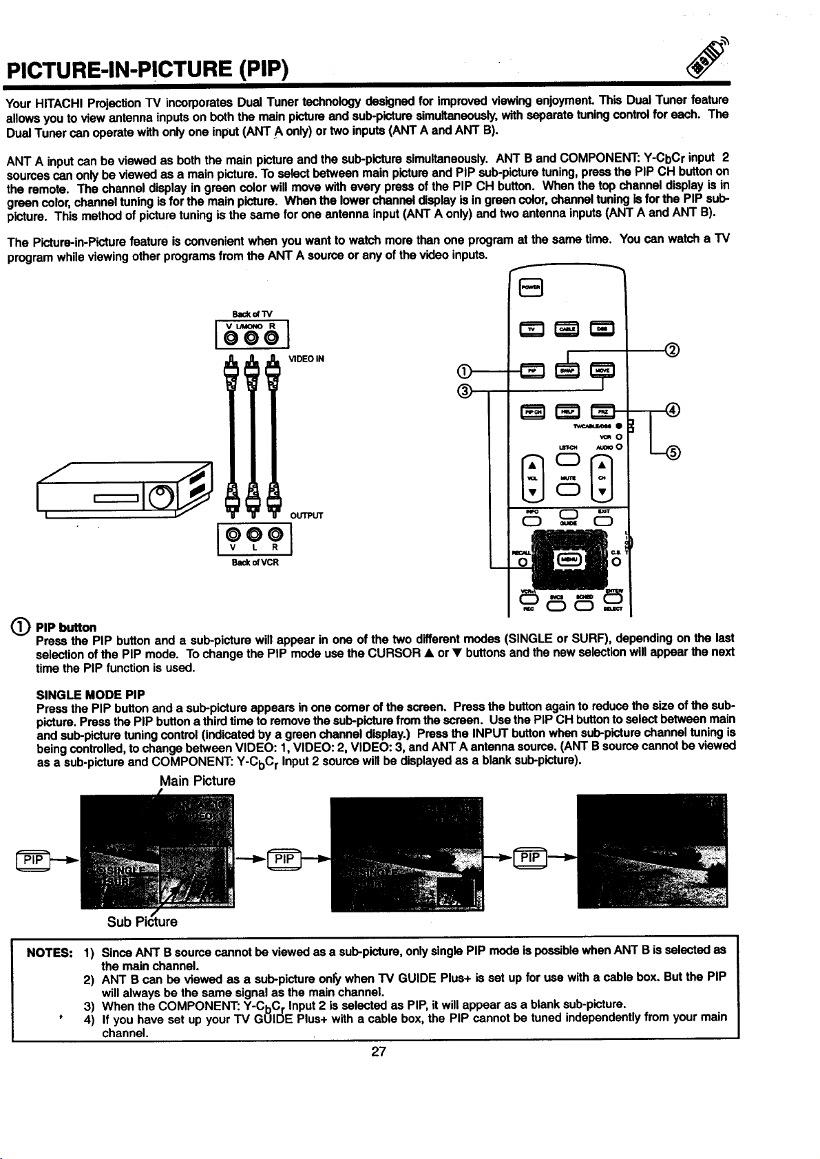
(_PIP button
Press the PIP button and a sub-picture will appear in one of the two different modes (SINGLE or SURF), depending on the last
selection of the PIP mode. To change the PIP mode use the CURSOR • or • buttons and the new selection will appear the next
time the PIP function is used.
SINGLE MODE PIP
Press the PIP button and a sub-picture appears in one comer of the screen. Press the button again to reduce the size of the sub-
picture. Press the PIP button a thirdtime to remove the sub-picture from the screen. Use the PIP CH button to select between main
and sub-picture tuning control (indicated by a green channel display.) Press the INPUT button when sub-picture channel tuning is
being controlled, to change between VIDEO: 1,VIDEO: 2, VIDEO: 3, and ANT A antenna soume. (ANT B source cannot be viewed
as a sub-picture and COMPONENT: Y-CbC r Input 2 source will be displayed as a blank sub-picture).
Main Picture
NOTES:
Sub
1) Since ANT B source cannot be viewed as a sub-picture, onlysingle PIP mode is possible when ANT B is selected as
the main channel.
2) ANT B can be viewed as a sub-picture only when TV GUIDE Plus+ is set up for use with a cable box. But the PIP
will always be the same signal as the main channel.
3) When the COMPONENT: Y-CbC r Input 2 is selected as PIP, it will appear as a blank sub-picture.
4) If you have set up your TV GUIDE Plus+ with a cable box, the PIP cannot be tuned independently from your main
channel.
27
 Loading...