

Page 1

SERVICE MANUAL
updated 9/21/05
version 0192.1
Manual 0191 is for
the following models:
42/50/60V710
42/50/60V715
50/60/70VS810
PA
No. 0192
42V515 LC46K
NN TT SS CC
This addendum PANO 0192 includes all information for the 42V515.
For all features / adjustments please refer to Service Manual PA No.
0191 when servicing.
LLCC4466KK
CChhaassssiiss
CONTENTS
The electrical and mechanical parts list only lists parts that are different from
Service Manual PA No. 0191
ELECTRICAL PARTS DIFFERENCES ................................................................................ 2
EXPLODED VIEW ................................................................................................................3
CIRCUIT DIAGRAMS ............................................................................................................5
REPLACEMENT PARTS LIST ............................................................................................24
R/C: CLU-3842WL or
CLU-3844WL
NOTE: If a part is not listed in this addendum, please refer to Service Manual PA No. 0191
CAUTION: These servicing instructions are for use by qualified service personnel only. To reduce the risk of
electric shock do not perform any servicing other than that contained in the operating instructions
unless you are qualified to do so.
SAFETY NOTICE
USE ISOLATION TRANSFORMER WHEN SERVICING
Components having special safety characteristics are identified by a on the schematics and on the parts list in this
Service Data and its supplements and bulletins. Before servicing the chassis, it is important that the service technician
read and follow the “Important Safety Instructions” in this Service Manual.
!
SPECIFICATIONS AND PARTS ARE SUBJECT TO CHANGE FOR IMPROVEMENT
LCD REAR PROJECTION TELEVISION
OCTOBER 2004 HHEA-MANUFACTURING DIVISION
Page 2
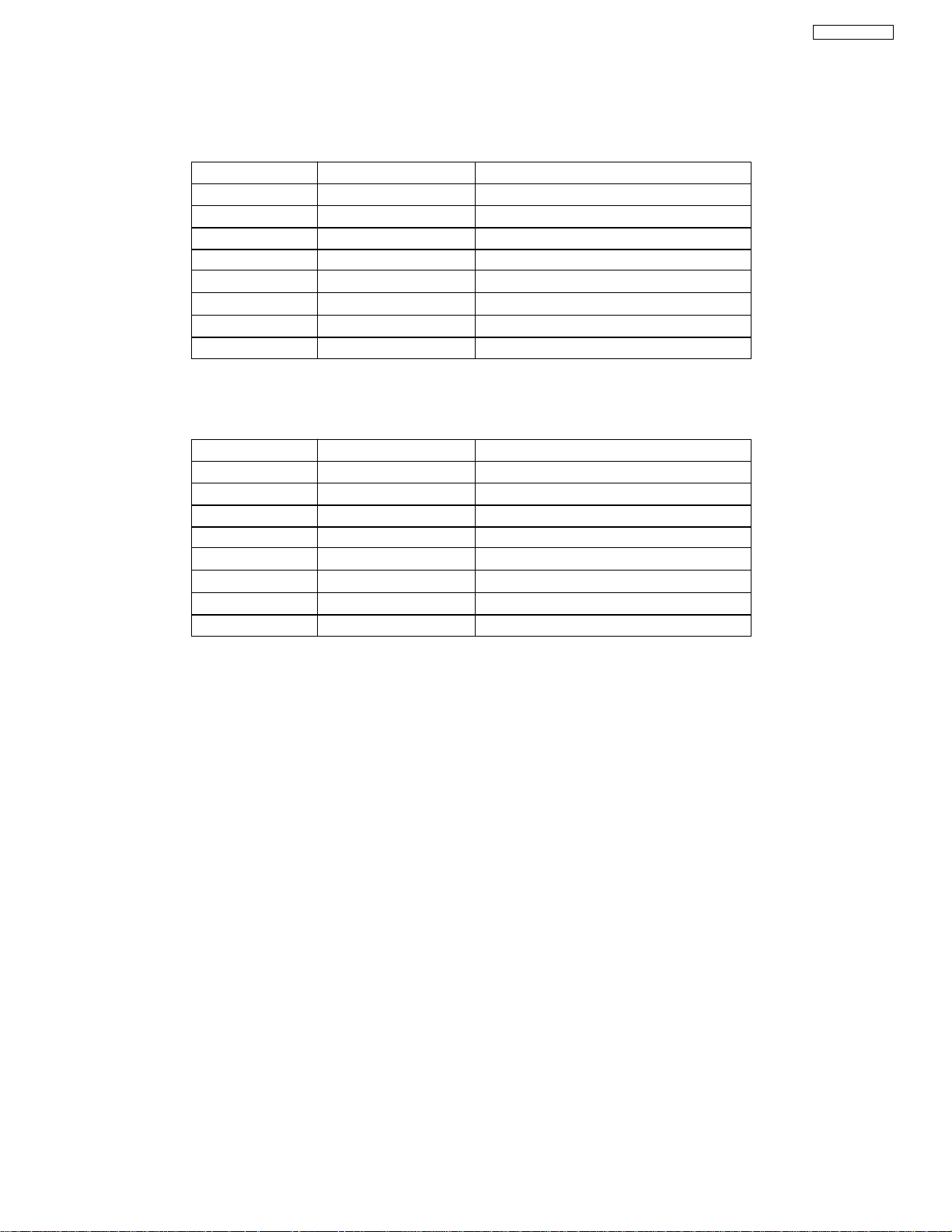
Main Part Differences between LC47K and LC46K
LC47K (42V710/715)
Symbol Part No. Description
EANT HP00773 Ant Switch
I004 CK50941U Main Micro M306V7MJ-504FP
I406 CK38377R DM +9V Regulator
U301 HC00496 Main Tuner
U302 HC00505 Sub Tuner
U901 HA01331 Power Supply
UV01 UE23411 DM HCY501
LC46K (42V515)
Symbol Part No. Description
EANT HP00772 Ant Switch
I004 CK50901U Main Micro M306V7MJ-503FP
I406 Not Used
U301 HC00515 Main Tuner
U302 HC00465 Sub Tuner
U901 HA01332 Power Supply
UV01 Not Used
LC46K
2
Page 3
LC46K
3
Page 4
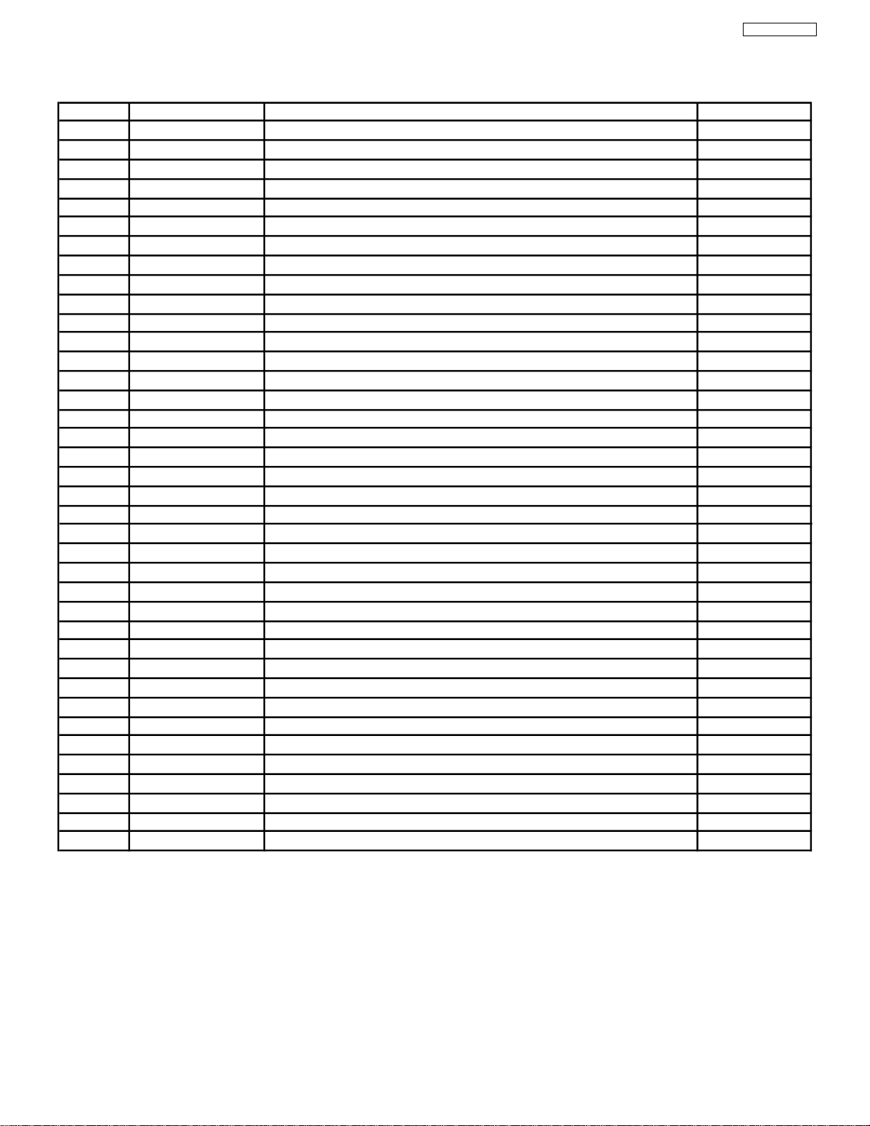
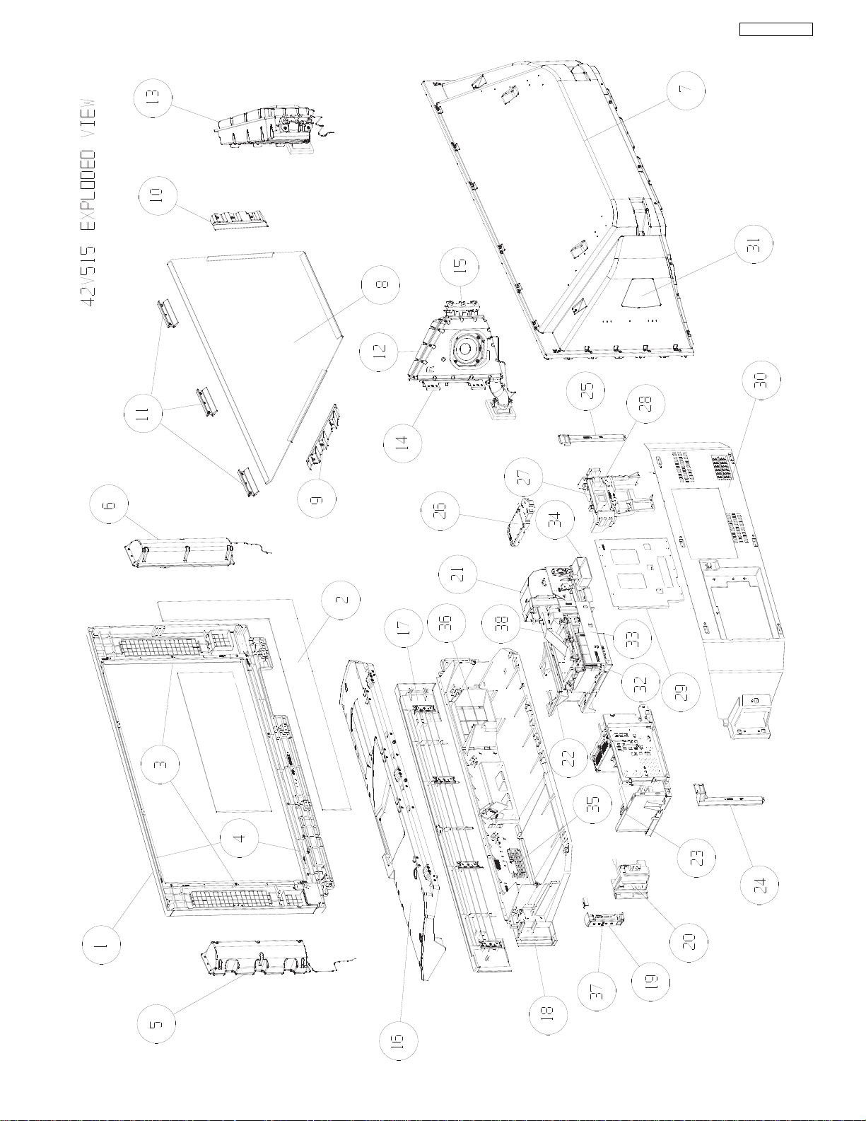
Model 42V515
No Part No Description Qty.
1 QD38213 SCREEN FRAME 42V515 1
2 KR03232 42V SCREEN ASSY 1
3 NA71651 SCR FIX ML V 2
4 NA71661 SCR FIX ML H 2
5 GM01491 SPEAKER 1
6 GM01481 SPEAKER 1
7 QD38221 MIRROR COVER 1
8 KS07892 1ST MIRROR 1
9 NJ09581 MIRR FIX PART R 42V 1
10 NJ09582 MIRR FIX PART L 42V 1
11 NJ09621 MIRR FIX P 3
12 GM01471 SPEAKER 1
13 GM01461 SPEAKER 1
14 NA72341 LC4X WOOFER UNIT FIX METAL FRO 2
15 NA72351 LC4X WOOFER UNIT FIX METAL REA 1
16 ME03711 BARRIER COV 1
17 PH34373 FRONT COVER 1
18 QD38233 LOW CABINET 1
19 PH34421 42VS701 SIDE CONTROL HOLDER 1
20 PH34431 42VS701 SIDE TERM HOLDER 1
21 UE23611 REAR 0.7R OPTICAL UNIT 42 1
22 ME03762 LENS BARRIER 1
23 UE23216 LC46K CHASSIS ASY 1
24 NJ09601 CABI SUPPORT R 42V 1
25 NJ09602 CABI SUPPORT L 42V 1
26 NT04371 LC47K POW SUB HOLDER 1
27 NT04121 LAMP POW HLD 1
28 HA01461 LAMP BALLAST 100W 1
29 NA71571 CABI BRACKET REAR 42 1
30 QD38241 LOW REAR COV 1
31 PH34721 SP_HOLE_PLATE 2
32 NA71581 CONT B FIX MTL 42V 1
33 NA72161 ENGINE BASE MTL 442V 1
34 NJ08351 LAMP DUCT C 1
35 PH34601 LO CABI COV F 42V 1
36 PH34283 LAMP COVER 1
37 PC06161 CONTROL BUTTON 1
38 NX30093 42V DRIVE DUCT 1
UX23681
CH 1
4
LC46K
Page 5
PRODUCT SAFETY NOTE: Components marked with a and shaded have special characteristics important to safety. Before replacing any of these components
, read carefully the PRODUCT SAFETY NOTICE of this Service Manual. Don’t degrade the safety of the receiver through improper servicing.
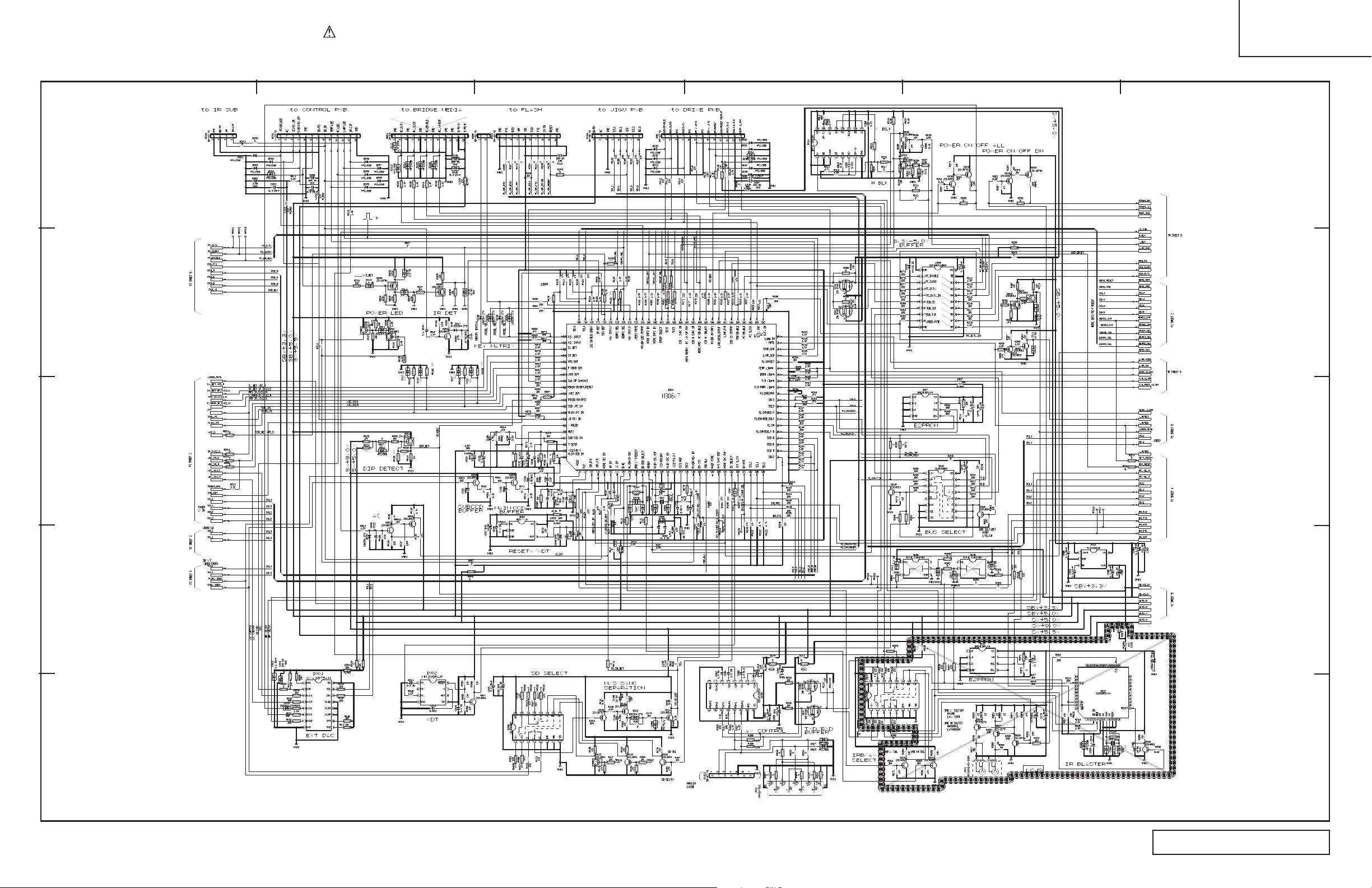
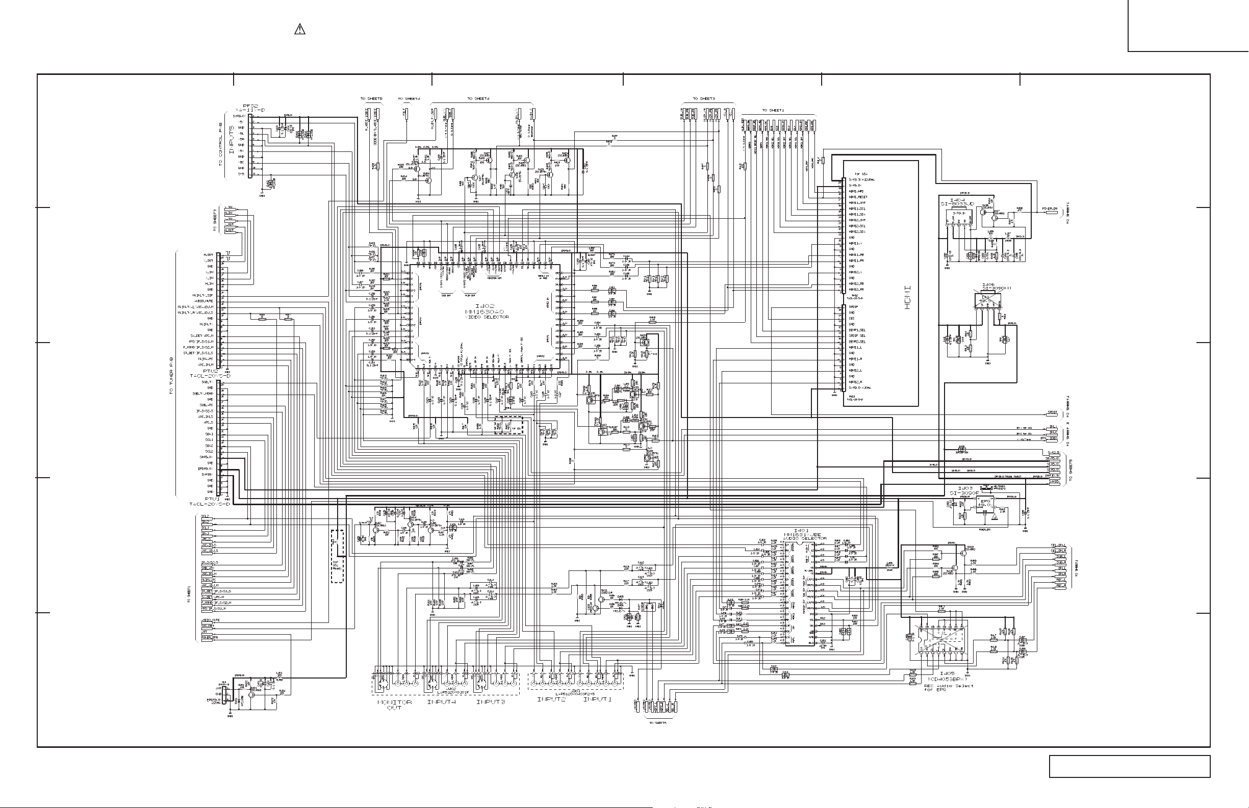
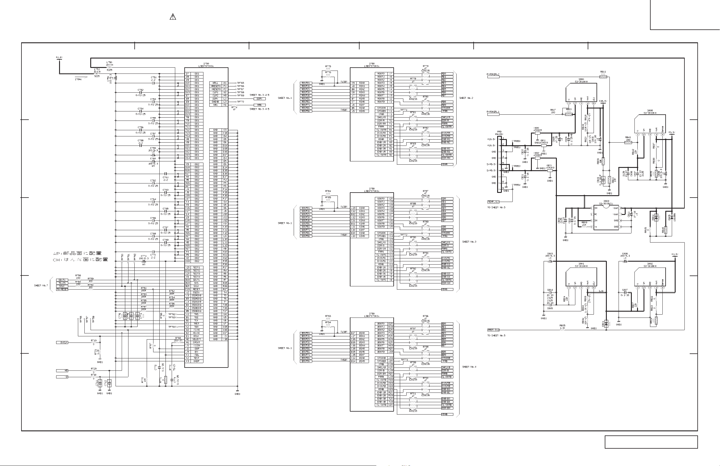
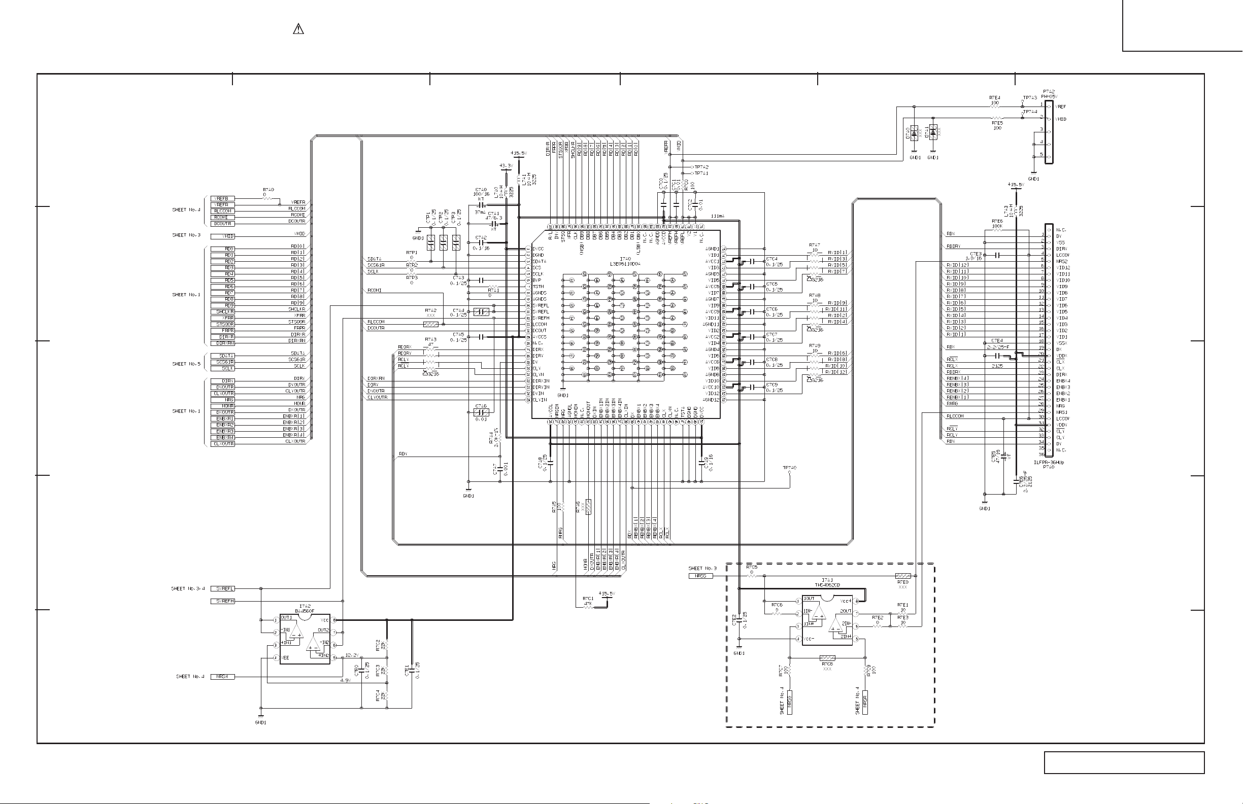
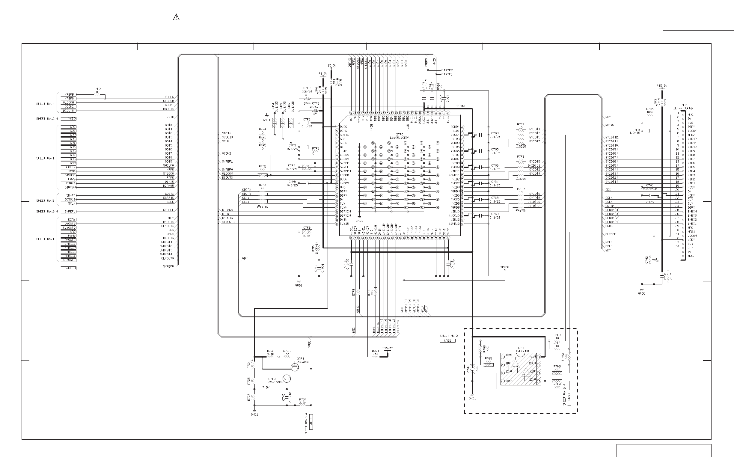
BASIC CIRCUIT DIAGRAM
LC46K
Signal 1 of 5
A
B
1234
5
6
C
D
E
O All DC voltage to be measured with a tester (100kh/V). Voltage taken on a complex color bar signal including a standard color bar signal.
O Since this is a basic circuit diagram, the value of the parts is subject to be altered for improvement.
5
Signal 1 of 5
Page 6
PRODUCT SAFETY NOTE: Components marked with a and shaded have special characteristics important to safety. Before replacing any of these components
, read carefully the PRODUCT SAFETY NOTICE of this Service Manual. Don’t degrade the safety of the receiver through improper servicing.
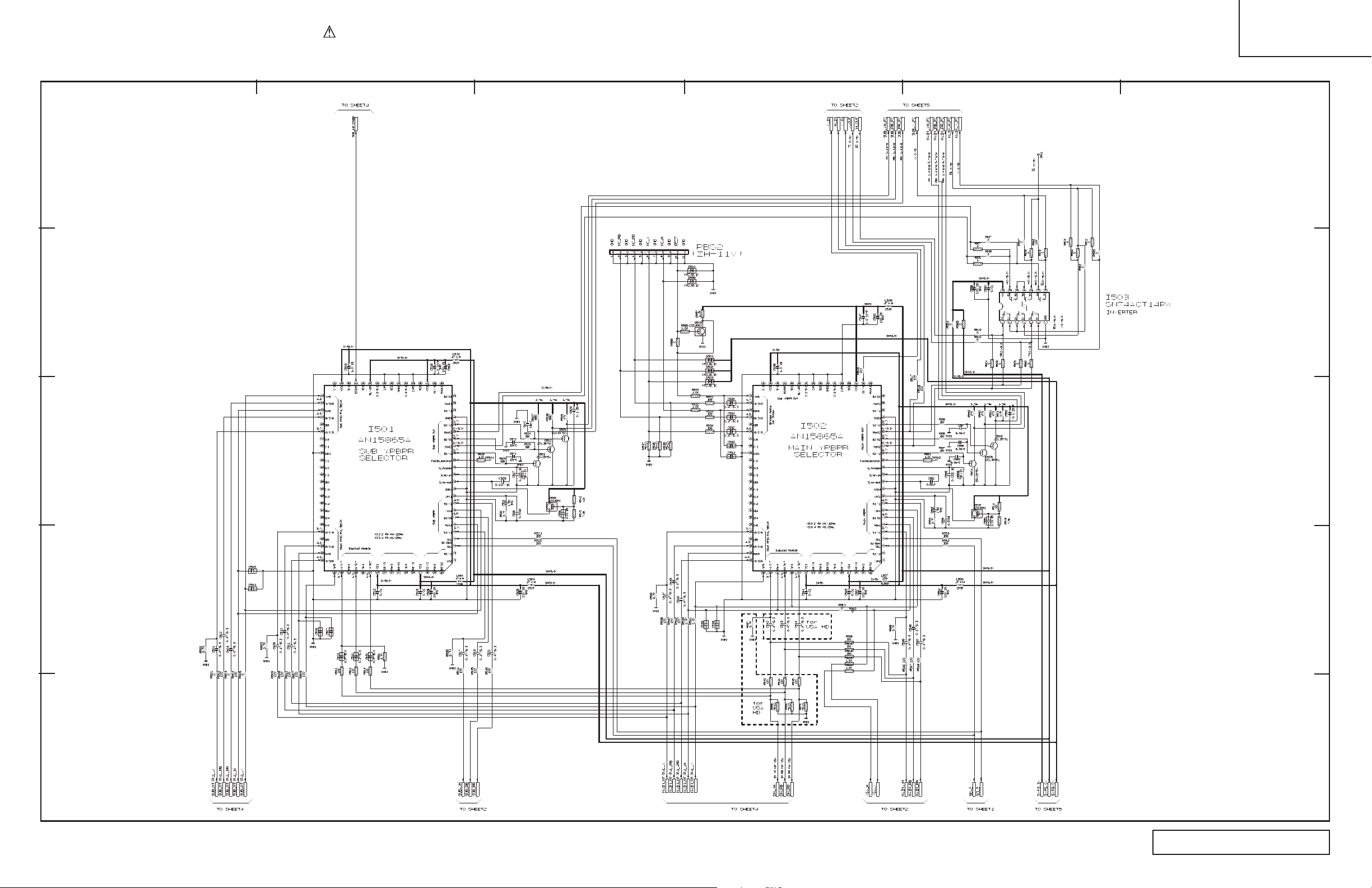
BASIC CIRCUIT DIAGRAM
LC46K
Signal 2 of 5
A
B
1234
5
6
C
D
E
O All DC voltage to be measured with a tester (100kh/V). Voltage taken on a complex color bar signal including a standard color bar signal.
O Since this is a basic circuit diagram, the value of the parts is subject to be altered for improvement.
6
Signal 2 of 5
Page 7
PRODUCT SAFETY NOTE: Components marked with a and shaded have special characteristics important to safety. Before replacing any of these components
, read carefully the PRODUCT SAFETY NOTICE of this Service Manual. Don’t degrade the safety of the receiver through improper servicing.
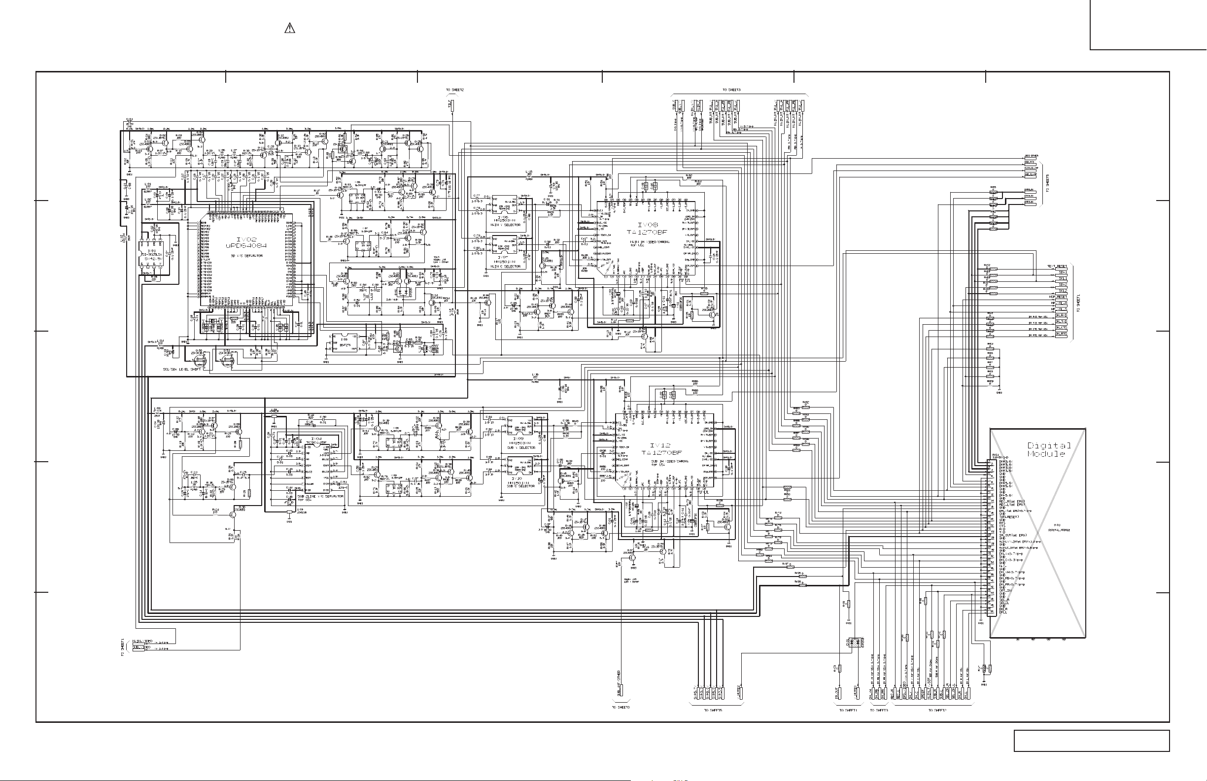
BASIC CIRCUIT DIAGRAM
LC46K
Signal 3 of 5
A
B
1234
5
6
C
D
E
O All DC voltage to be measured with a tester (100kh/V). Voltage taken on a complex color bar signal including a standard color bar signal.
O Since this is a basic circuit diagram, the value of the parts is subject to be altered for improvement.
7
Signal 3 of 5
Page 8
PRODUCT SAFETY NOTE: Components marked with a and shaded have special characteristics important to safety. Before replacing any of these components
, read carefully the PRODUCT SAFETY NOTICE of this Service Manual. Don’t degrade the safety of the receiver through improper servicing.
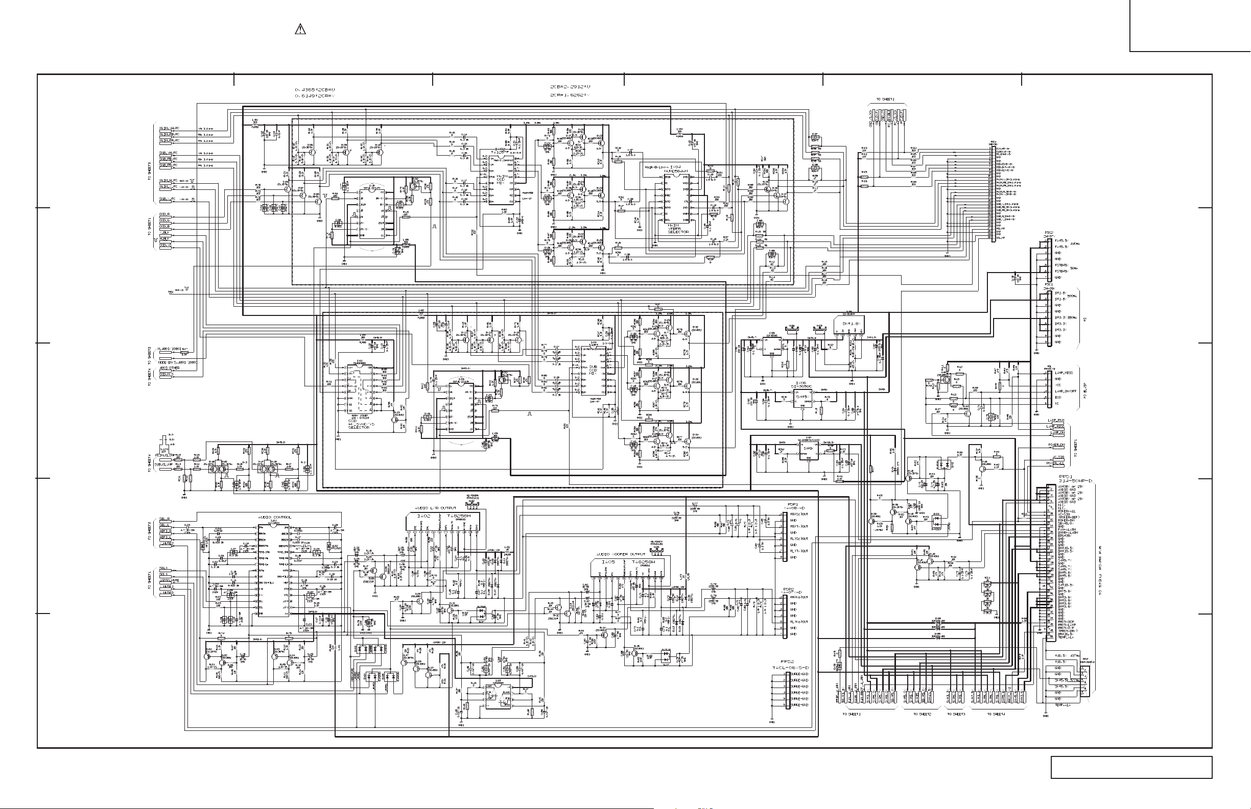
BASIC CIRCUIT DIAGRAM
LC46K
Signal 4 of 5
A
B
1234
5
6
C
D
E
O All DC voltage to be measured with a tester (100kh/V). Voltage taken on a complex color bar signal including a standard color bar signal.
O Since this is a basic circuit diagram, the value of the parts is subject to be altered for improvement.
8
Signal 4 of 5
Page 9
PRODUCT SAFETY NOTE: Components marked with a and shaded have special characteristics important to safety. Before replacing any of these components
, read carefully the PRODUCT SAFETY NOTICE of this Service Manual. Don’t degrade the safety of the receiver through improper servicing.
BASIC CIRCUIT DIAGRAM
LC46K
Signal 5 of 5
A
B
1234
5
6
C
D
E
O All DC voltage to be measured with a tester (100kh/V). Voltage taken on a complex color bar signal including a standard color bar signal.
O Since this is a basic circuit diagram, the value of the parts is subject to be altered for improvement.
9
Signal 5 of 5
Page 10
PRODUCT SAFETY NOTE: Components marked with a and shaded have special characteristics important to safety. Before replacing any of these components
, read carefully the PRODUCT SAFETY NOTICE of this Service Manual. Don’t degrade the safety of the receiver through improper servicing.
BASIC CIRCUIT DIAGRAM
LC46K
Drive 1 of 9
A
B
1234
5
6
C
D
E
O All DC voltage to be measured with a tester (100kh/V). Voltage taken on a complex color bar signal including a standard color bar signal.
O Since this is a basic circuit diagram, the value of the parts is subject to be altered for improvement.
10
Drive 1 of 9
Page 11
PRODUCT SAFETY NOTE: Components marked with a and shaded have special characteristics important to safety. Before replacing any of these components
, read carefully the PRODUCT SAFETY NOTICE of this Service Manual. Don’t degrade the safety of the receiver through improper servicing.
BASIC CIRCUIT DIAGRAM
LC46K
Drive 2 of 9
A
B
1234
5
6
C
D
E
O All DC voltage to be measured with a tester (100kh/V). Voltage taken on a complex color bar signal including a standard color bar signal.
O Since this is a basic circuit diagram, the value of the parts is subject to be altered for improvement.
11
Drive 2 of 9
Page 12
PRODUCT SAFETY NOTE: Components marked with a and shaded have special characteristics important to safety. Before replacing any of these components
, read carefully the PRODUCT SAFETY NOTICE of this Service Manual. Don’t degrade the safety of the receiver through improper servicing.
BASIC CIRCUIT DIAGRAM
LC46K
Drive 3 of 9
A
B
1234
5
6
C
D
E
O All DC voltage to be measured with a tester (100kh/V). Voltage taken on a complex color bar signal including a standard color bar signal.
O Since this is a basic circuit diagram, the value of the parts is subject to be altered for improvement.
12
Drive 3 of 9
Page 13

PRODUCT SAFETY NOTE: Components marked with a and shaded have special characteristics important to safety. Before replacing any of these components
, read carefully the PRODUCT SAFETY NOTICE of this Service Manual. Don’t degrade the safety of the receiver through improper servicing.
BASIC CIRCUIT DIAGRAM
LC46K
Drive 4 of 9
A
B
1234
5
6
C
D
E
O All DC voltage to be measured with a tester (100kh/V). Voltage taken on a complex color bar signal including a standard color bar signal.
O Since this is a basic circuit diagram, the value of the parts is subject to be altered for improvement.
13
Drive 4 of 9
Page 14

PRODUCT SAFETY NOTE: Components marked with a and shaded have special characteristics important to safety. Before replacing any of these components
, read carefully the PRODUCT SAFETY NOTICE of this Service Manual. Don’t degrade the safety of the receiver through improper servicing.
BASIC CIRCUIT DIAGRAM
LC46K
Drive 5 of 9
A
B
1234
5
6
C
D
E
O All DC voltage to be measured with a tester (100kh/V). Voltage taken on a complex color bar signal including a standard color bar signal.
O Since this is a basic circuit diagram, the value of the parts is subject to be altered for improvement.
14
Drive 5 of 9
Page 15

PRODUCT SAFETY NOTE: Components marked with a and shaded have special characteristics important to safety. Before replacing any of these components
, read carefully the PRODUCT SAFETY NOTICE of this Service Manual. Don’t degrade the safety of the receiver through improper servicing.
BASIC CIRCUIT DIAGRAM
LC46K
Drive 6 of 9
A
B
1234
5
6
C
D
E
O All DC voltage to be measured with a tester (100kh/V). Voltage taken on a complex color bar signal including a standard color bar signal.
O Since this is a basic circuit diagram, the value of the parts is subject to be altered for improvement.
15
Drive 6 of 9
Page 16

PRODUCT SAFETY NOTE: Components marked with a and shaded have special characteristics important to safety. Before replacing any of these components
, read carefully the PRODUCT SAFETY NOTICE of this Service Manual. Don’t degrade the safety of the receiver through improper servicing.
BASIC CIRCUIT DIAGRAM
LC46K
Drive 7 of 9
A
B
1234
5
6
C
D
E
O All DC voltage to be measured with a tester (100kh/V). Voltage taken on a complex color bar signal including a standard color bar signal.
O Since this is a basic circuit diagram, the value of the parts is subject to be altered for improvement.
16
Drive 7 of 9
Page 17

PRODUCT SAFETY NOTE: Components marked with a and shaded have special characteristics important to safety. Before replacing any of these components
, read carefully the PRODUCT SAFETY NOTICE of this Service Manual. Don’t degrade the safety of the receiver through improper servicing.
BASIC CIRCUIT DIAGRAM
LC46K
Drive 8 of 9
A
B
1234
5
6
C
D
E
O All DC voltage to be measured with a tester (100kh/V). Voltage taken on a complex color bar signal including a standard color bar signal.
O Since this is a basic circuit diagram, the value of the parts is subject to be altered for improvement.
17
Drive 8 of 9
Page 18

PRODUCT SAFETY NOTE: Components marked with a and shaded have special characteristics important to safety. Before replacing any of these components
, read carefully the PRODUCT SAFETY NOTICE of this Service Manual. Don’t degrade the safety of the receiver through improper servicing.
BASIC CIRCUIT DIAGRAM
LC46K
Drive 9 of 9
A
B
1234
5
6
C
D
E
O All DC voltage to be measured with a tester (100kh/V). Voltage taken on a complex color bar signal including a standard color bar signal.
O Since this is a basic circuit diagram, the value of the parts is subject to be altered for improvement.
18
Drive 9 of 9
Page 19

PRODUCT SAFETY NOTE: Components marked with a and shaded have special characteristics important to safety. Before replacing any of these components
, read carefully the PRODUCT SAFETY NOTICE of this Service Manual. Don’t degrade the safety of the receiver through improper servicing.
BASIC CIRCUIT DIAGRAM
LC46K
Cont 1 of 2
A
B
1234
5
6
C
D
E
O All DC voltage to be measured with a tester (100kh/V). Voltage taken on a complex color bar signal including a standard color bar signal.
O Since this is a basic circuit diagram, the value of the parts is subject to be altered for improvement.
19
Cont 1 of 2
Page 20

PRODUCT SAFETY NOTE: Components marked with a and shaded have special characteristics important to safety. Before replacing any of these components
, read carefully the PRODUCT SAFETY NOTICE of this Service Manual. Don’t degrade the safety of the receiver through improper servicing.
BASIC CIRCUIT DIAGRAM
LC46K
Cont 2 of 2
A
B
1234
5
6
C
D
E
O All DC voltage to be measured with a tester (100kh/V). Voltage taken on a complex color bar signal including a standard color bar signal.
O Since this is a basic circuit diagram, the value of the parts is subject to be altered for improvement.
20
Cont 2 of 2
Page 21

PRODUCT SAFETY NOTE: Components marked with a and shaded have special characteristics important to safety. Before replacing any of these components
, read carefully the PRODUCT SAFETY NOTICE of this Service Manual. Don’t degrade the safety of the receiver through improper servicing.
BASIC CIRCUIT DIAGRAM
LC46K
HDMI
A
B
1234
5
6
C
D
E
O All DC voltage to be measured with a tester (100kh/V). Voltage taken on a complex color bar signal including a standard color bar signal.
O Since this is a basic circuit diagram, the value of the parts is subject to be altered for improvement.
21
HDMI
Page 22

PRODUCT SAFETY NOTE: Components marked with a and shaded have special characteristics important to safety. Before replacing any of these components
, read carefully the PRODUCT SAFETY NOTICE of this Service Manual. Don’t degrade the safety of the receiver through improper servicing.
BASIC CIRCUIT DIAGRAM
LC46K
Lamp Power
A
B
1234
5
6
C
D
E
O All DC voltage to be measured with a tester (100kh/V). Voltage taken on a complex color bar signal including a standard color bar signal.
O Since this is a basic circuit diagram, the value of the parts is subject to be altered for improvement.
22
Lamp Power
Page 23

PRODUCT SAFETY NOTE: Components marked with a and shaded have special characteristics important to safety. Before replacing any of these components
, read carefully the PRODUCT SAFETY NOTICE of this Service Manual. Don’t degrade the safety of the receiver through improper servicing.
BASIC CIRCUIT DIAGRAM
LC46K
Tuner
A
B
1234
5
6
C
D
E
O All DC voltage to be measured with a tester (100kh/V). Voltage taken on a complex color bar signal including a standard color bar signal.
O Since this is a basic circuit diagram, the value of the parts is subject to be altered for improvement.
23
Tuner
Page 24

REPLACEMENT PARTS LIST
Capacitors:
Resistors: Semiconductors:
AL: Aluminum Electrolytic
CF: Carbon Film TR: Transistor
CD: Ceramic Disc
CC: Carbon Composition DI: Diode
EL: Electrolitic
MF: Metal Oxide ZD: Zener Diode
PF: Polyester Film
VR: Variable Resistor VA: Varistor
PP: Polypropylene
WW: Wire Wound TH: Termistor
PL: Plastic
FR: Fuse Resistor IC: Integrated Circuit
TA: Tantalum
MG: Metal Grazed
PR: Paper
TM: Trimmer
MC: Mylar
ABBREVIATIONS
SYMBOL
NO.
PART
NO.
PART
DESCRIPTION
SYMBOL
NO.
PART
NO.
PART
DESCRIPTION
LC46K
PRODUCT SERVICE NOTE: Components marked with a have special characteristics important to safety. Before replacing any
of these components
, read carefully, the PRODUCT SAFETY NOTICE of this Service Manual. Don’t degrade the safety of the
!
receiver through improper servicing.
SIGNAL PWB
JT24546 LC46K SIGNAL PWB ASY
C001 0800279R CAP.-ELECTORO. 1.0UF-M(SMG) 50V
C002 0893232R CAP 1608CHIP 100000PFZF25V TAPE
C005 0800326R CAP.-ELECTRO. 100UF-M 16V
C006 0893232R CAP 1608CHIP 100000PFZF25V TAPE
C009 0893213R CAP1608CHIP 2200PFKB 50V TAPE
C011 AA01141R CERAMIC CAPACITOR(0.1UF 16V)
C013 0893232R CAP 1608CHIP 100000PFZF25V TAPE
C014 0893208R CAP 1608CHIP 1000PFKB 50V TAPE
C018 AA01141R CERAMIC CAPACITOR(0.1UF 16V)
C019 0800294R CAP.-ELECTRO. 10UF-M(SMG) 50V
C020
C024 0800326R CAP.-ELECTRO. 100UF-M 16V
C025 0893232R CAP 1608CHIP 100000PFZF25V TAPE
C026 0800279R CAP.-ELECTORO. 1.0UF-M(SMG) 50V
C027 0800326R CAP.-ELECTRO. 100UF-M 16V
C028 0893232R CAP 1608CHIP 100000PFZF25V TAPE
C029 0893205R CAP 1608CHIP 560PFKB 50V TAPE
C030 0893204R CAP 1608CHIP 470PFKB 50V TAPE
C031 0893232R CAP 1608CHIP 100000PFZF25V TAPE
C032 0893208R CAP 1608CHIP 1000PFKB 50V TAPE
C033 0800326R CAP.-ELECTRO. 100UF-M 16V
C034 0800282R CAP.-ELECTORO. 2.2UF-M(SMG) 50V
C035 0800279R CAP.-ELECTORO. 1.0UF-M(SMG) 50V
C036 0893131R CAP 1608CHIP 220PFJCH 50V TAPE
C037 0893204R CAP 1608CHIP 470PFKB 50V TAPE
C038 0893208R CAP 1608CHIP 1000PFKB 50V TAPE
C039 0800282R CAP.-ELECTORO. 2.2UF-M(SMG) 50V
C040
C041 0800326R CAP.-ELECTRO. 100UF-M 16V
C042 0893131R CAP 1608CHIP 220PFJCH 50V TAPE
C043 0893232R CAP 1608CHIP 100000PFZF25V TAPE
C044 0893222R CAP 1608CHIP10000PFKB 50V TAPE
C046 0893208R CAP 1608CHIP 1000PFKB 50V TAPE
C048 0800303R CAP.-ELECTRO. 22UF-M 50V
C050 0800326R CAP.-ELECTRO. 100UF-M 16V
C051 0893222R CAP 1608CHIP10000PFKB 50V TAPE
C052 0893232R CAP 1608CHIP 100000PFZF25V TAPE
C054 0893104R CAP 1608CHIP 2PFCCK 50V TAPE
C056 0893245R CAP 1608CHIP 15000PFKB 50V TAPE
C058 0893222R CAP 1608CHIP10000PFKB 50V TAPE
C059 0893222R CAP 1608CHIP10000PFKB 50V TAPE
C060
C061
C062
C063 AA01111R CERAMIC CAPACITOR(1.0UF 6.3V)
C064
C066
C070
C071
C072 0893232R CAP 1608CHIP 100000PFZF25V TAPE
C075 0800326R CAP.-ELECTRO. 100UF-M 16V
C080 0893232R
C081 AA01101R
C085 0893232R
C086 0800326R
C089 0893232R CAP 1608CHIP 100000PFZF25V TAPE
C090 0800326R CAP.-ELECTRO. 100UF-M 16V
C092 0893232R
TABLE OF CONTENTS
0893205R CAP 1608CHIP 560PFKB 50V TAPE
0800294R CAP.-ELECTRO. 10UF-M(SMG) 50V
AA01144R
AA01144R
AA01111R
0893232R CAP 1608CHIP 100000PFZF25V TAPE
0800326R
0893232R
0893232R
CAPACITORS
1608-B 1.0UF 16V
.-ELECTR
.-ELECTR
.
1608-B 1.0UF 16V
.
CIT
A
O. 100UF-M 16V
ACITOR(1UF 10V-F)
100UF-M 16V
.
O
CERAMIC CAP
CERAMIC CAP
CERAMIC CAP
CAP
CAP 1608CHIP 100000PFZF25V
CAP 1608CHIP 100000PFZF25V
CAP 1608CHIP 100000PFZF25V TAPE
CERAMIC CAP
CAP 1608CHIP 100000PFZF25V
CAP
CAP 1608CHIP 100000PFZF25V TAPE
OR(1.0UF 6.3V)
APE
T
APE
T
APE
T
C094 0893208R CAP 1608CHIP 1000PFKB 50V TAPE
C095 0893208R CAP 1608CHIP 1000PFKB 50V TAPE
C096 0893232R CAP 1608CHIP 100000PFZF25V TAPE
C097 0800326R CAP.-ELECTRO. 100UF-M 16V
C098 0893232R CAP 1608CHIP 100000PFZF25V TAPE
C401 0800326R CAP.-ELECTRO. 100UF-M 16V
C402 0893232R CAP 1608CHIP 100000PFZF25V TAPE
C403 0893232R CAP 1608CHIP 100000PFZF25V TAPE
C404 0800326R CAP.-ELECTRO. 100UF-M 16V
C405 0800294R CAP.-ELECTRO. 10UF-M(SMG) 50V
C406 AA01123R CCC105K10-B-16CT
C407 AA01123R CCC105K10-B-16CT
C408 0893232R CAP 1608CHIP 100000PFZF25V TAPE
C409 AA01123R CCC105K10-B-16CT
C410 AA01123R CCC105K10-B-16CT
C411 0893232R CAP 1608CHIP 100000PFZF25V TAPE
C412
C413 AA01123R CCC105K10-B-16CT
C414 0893232R CAP 1608CHIP 100000PFZF25V TAPE
C415 0800326R CAP.-ELECTRO. 100UF-M 16V
C416 0893239R CAP 1608CHIP 10000PFZF 50V TAPE
C417 AA01123R CCC105K10-B-16CT
C418 AA01123R CCC105K10-B-16CT
C420 AA01123R CCC105K10-B-16CT
C421 AA01123R CCC105K10-B-16CT
C422 0893232R CAP 1608CHIP 100000PFZF25V TAPE
C423 AA01123R CCC105K10-B-16CT
C424 0893232R CAP 1608CHIP 100000PFZF25V TAPE
C426 0893232R CAP 1608CHIP 100000PFZF25V TAPE
C427 0893222R CAP 1608CHIP10000PFKB 50V TAPE
C428 0893232R CAP 1608CHIP 100000PFZF25V TAPE
C429 AA01123R CCC105K10-B-16CT
C430 0800352R CAP.-ELECTRO.470UF 10V
C431
C432 AA01123R CCC105K10-B-16CT
C433 AA00966R CERAMIC CAPACITOR(4.7UF 6.3V)
C434 AA00966R CERAMIC CAPACITOR(4.7UF 6.3V)
C435 0893232R CAP 1608CHIP 100000PFZF25V TAPE
C436 0893232R CAP 1608CHIP 100000PFZF25V TAPE
C437 AA01123R CCC105K10-B-16CT
C438 0800303R CAP.-ELECTRO. 22UF-M 50V
C439 0893232R CAP 1608CHIP 100000PFZF25V TAPE
C441 0893232R CAP 1608CHIP 100000PFZF25V TAPE
C442 AA01123R CCC105K10-B-16CT
C443 AA01123R CCC105K10-B-16CT
C444 AA01123R CCC105K10-B-16CT
C445 AA01123R CCC105K10-B-16CT
C446
C447
C448
C449 0893232R CAP 1608CHIP 100000PFZF25V TAPE
C450
C454
C455
C456
C461 AA00966R CERAMIC CAPACITOR(4.7UF 6.3V)
C462 AA00966R CERAMIC CAPACITOR(4.7UF 6.3V)
C463
C464
C465
C466
C467 AA01123R CCC105K10-B-16CT
C468 AA01123R CCC105K10-B-16CT
C469
AA01123R CCC105K10-B-16CT
0800352R CAP.-ELECTRO.470UF 10V
AA01123R
AA01123R
AA01123R
0800352R CAP.-ELECTRO.470UF 10V
AA01123R
AA01123R
AA01123R
AA01123R
AA01123R
AA01123R
AA01123R
AA01123R
CCC105K10-B-16CT
CCC105K10-B-16CT
CCC105K10-B-16CT
CCC105K10-B-16CT
CCC105K10-B-16CT
CCC105K10-B-16CT
CCC105K10-B-16CT
CCC105K10-B-16CT
CCC105K10-B-16CT
CCC105K10-B-16CT
CCC105K10-B-16CT
24
Page 25

LC46K
SYMBOL
NO.
PART
NO.
PART
DESCRIPTION
SYMBOL
NO.
PART
NO.
PART
DESCRIPTION
PRODUCT SERVICE NOTE: Components marked with a have special characteristics important to safety. Before replacing any
!
of these components, read carefully, the PRODUCT SAFETY NOTICE of this Service Manual. Don’t degrade the safety of the
er through improper servicing.
receiv
C470 AA01123R CCC105K10-B-16CT
C471 AA01123R CCC105K10-B-16CT
C472 AA01123R CCC105K10-B-16CT
C474 AA01111R CERAMIC CAPACITOR(1.0UF 6.3V)
C475 AA01123R CCC105K10-B-16CT
C476 AA01123R CCC105K10-B-16CT
C479 AA01123R CCC105K10-B-16CT
C480 AA01123R CCC105K10-B-16CT
C481 0800303R CAP.-ELECTRO. 22UF-M 50V
C482 0893222R CAP 1608CHIP10000PFKB 50V TAPE
C484 AA01123R CCC105K10-B-16CT
C485 AA01123R CCC105K10-B-16CT
C486 AA01123R CCC105K10-B-16CT
C487 AA01123R CCC105K10-B-16CT
C488 0800326R CAP.-ELECTRO. 100UF-M 16V
C490 AL01849R 1000UF 16V ALUMINIUM ELECTROLYTIC CAPACITOR
C492 0800352R CAP.-ELECTRO.470UF 10V
C493 0893208R CAP 1608CHIP 1000PFKB 50V TAPE
C494 AL01833R 1000UF 6.3V ALUMINIUM ELECTROLYTIC CAPACITOR
C495
C496 0893232R CAP 1608CHIP 100000PFZF25V TAPE
C4A2 AA00966R CERAMIC CAPACITOR(4.7UF 6.3V)
C4A3 AA00966R CERAMIC CAPACITOR(4.7UF 6.3V)
C4A4 AA00966R CERAMIC CAPACITOR(4.7UF 6.3V)
C4A5 AA00966R CERAMIC CAPACITOR(4.7UF 6.3V)
C4A6 AA01123R CCC105K10-B-16CT
C4C2 0893114R CAP 1608CHIP 12PFJCH 50V TAPE
C4C3 0893114R CAP 1608CHIP 12PFJCH 50V TAPE
C4C4 0893114R CAP 1608CHIP 12PFJCH 50V TAPE
C501
C502 AA01136R CERAMIC CAPACITOR(0.47UF 6.3V)
C503 AA01136R CERAMIC CAPACITOR(0.47UF 6.3V)
C508 AA01136R CERAMIC CAPACITOR(0.47UF 6.3V)
C509 AA01144R CERAMIC CAP. 1608-B 1.0UF 16V
C510 AA01136R CERAMIC CAPACITOR(0.47UF 6.3V)
C511 AA01136R CERAMIC CAPACITOR(0.47UF 6.3V)
C512 AA01802R CCC103K50-B-16CT MCH18
C516 AA01802R CCC103K50-B-16CT MCH18
C517 AA01136R CERAMIC CAPACITOR(0.47UF 6.3V)
C518 AA01101R CERAMIC CAPACITOR(1UF 10V-F)
C519 AA01136R CERAMIC CAPACITOR(0.47UF 6.3V)
C521 AA01136R CERAMIC CAPACITOR(0.47UF 6.3V)
C523 0893188R CERAMIC CAPACITOR(47000PF 16V)
C524 0800279R CAP.-ELECTORO. 1.0UF-M(SMG) 50V
C525 0800326R CAP.-ELECTRO. 100UF-M 16V
C526 0893215R CAP 1608CHIP 3300PFKB 50V TAPE
C527 0893184R CERAMIC CAPACITOR(22000PF 16V)
C528 0800326R CAP.-ELECTRO. 100UF-M 16V
C529 0893232R CAP 1608CHIP 100000PFZF25V TAPE
C537 AA01136R CERAMIC CAPACITOR(0.47UF 6.3V)
C538 AA01144R CERAMIC CAP. 1608-B 1.0UF 16V
C539 AA01136R CERAMIC CAPACITOR(0.47UF 6.3V)
C540
C541
C542 AA01136R CERAMIC CAPACITOR(0.47UF 6.3V)
C543 AA01136R CERAMIC CAPACITOR(0.47UF 6.3V)
C544
C545
C546
C547 AA01101R CERAMIC CAPACITOR(1UF 10V-F)
C548 AA01136R CERAMIC CAPACITOR(0.47UF 6.3V)
C550 AA01136R CERAMIC CAPACITOR(0.47UF 6.3V)
C552
C553
C554
C555 0893215R CAP 1608CHIP 3300PFKB 50V TAPE
C556 0893184R CERAMIC CAPACITOR(22000PF 16V)
C557 0800326R CAP.-ELECTRO. 100UF-M 16V
C558
C559
C560 AA01802R CCC103K50-B-16CT MCH18
C562 0800326R CAP.-ELECTRO. 100UF-M 16V
C563 0800326R CAP.-ELECTRO. 100UF-M 16V
C567 0893108R CAP 1608CHIP 6PFCCH 50V TAPE
C568
C569
C570 0893114R CAP 1608CHIP 12PFJCH 50V TAPE
C571 0893114R CAP 1608CHIP 12PFJCH 50V TAPE
C572 0893114R CAP 1608CHIP 12PFJCH 50V TAPE
CA01 AA00936R CERAMIC CAP. 2125-X5R 4.7UF 10V
CA02 AA01141R
CA03 AA00936R CERAMIC CAP. 2125-X5R 4.7UF 10V
CA04 0893215R CAP 1608CHIP 3300PFKB 50V TAPE
CA05 0893186R CERAMIC CAPACITOR(33000PF 16V)
CA06 0893217R CAP 1608CHIP 4700PFKB 50V TAPE
CA10 AA01123R CCC105K10-B-16CT
AL01833R 1000UF 6.3V ALUMINIUM ELECTROLYTIC CAPACITOR
AA01136R CERAMIC CAPACITOR(0.47UF 6.3V)
AA01136R
AA01802R
AA01136R CERAMIC CAPACITOR(0.47UF 6.3V)
AA01802R
AA01136R
0893217R CAP 1608CHIP 4700PFKB 50V TAPE
0800279R
0800326R
0800326R
0893232R
0893108R
0893108R
CERAMIC CAPACITOR(0.47UF 6.3V)
CCC103K50-B-16CT MCH18
CCC103K50-B-16CT MCH18
CERAMIC CAP
.-ELECTORO. 1.0UF-M(SMG) 50V
CAP
.-ELECTR
CAP
CAP.-ELECTRO. 100UF-M 16V
CAP 1608CHIP 100000PFZF25V
CAP 1608CHIP 6PFCCH 50V TAPE
CAP 1608CHIP 6PFCCH 50V
CERAMIC CAPACITOR(0.1UF 16V)
OR(0.47UF 6.3V)
CIT
A
100UF-M 16V
.
O
T
T
APE
APE
CA11 0893184R CERAMIC CAPACITOR(22000PF 16V)
CA13 AA00936R CERAMIC CAP. 2125-X5R 4.7UF 10V
CA14 AA00936R CERAMIC CAP. 2125-X5R 4.7UF 10V
CA15 0800294R CAP.-ELECTRO. 10UF-M(SMG) 50V
CA16 0893215R CAP 1608CHIP 3300PFKB 50V TAPE
CA17 0893186R CERAMIC CAPACITOR(33000PF 16V)
CA18 0893217R CAP 1608CHIP 4700PFKB 50V TAPE
CA19 0800288R CAP.-ELECTRO. 4.7UF-M(SMG) 50V
CA20 AA00936R CERAMIC CAP. 2125-X5R 4.7UF 10V
CA21 AA00936R CERAMIC CAP. 2125-X5R 4.7UF 10V
CA24 AA01141R CERAMIC CAPACITOR(0.1UF 16V)
CA25 0800294R CAP.-ELECTRO. 10UF-M(SMG) 50V
CA26 AA00936R CERAMIC CAP. 2125-X5R 4.7UF 10V
CA27 0893239R CAP 1608CHIP 10000PFZF 50V TAPE
CA28 AA00936R CERAMIC CAP. 2125-X5R 4.7UF 10V
CA29 0893221R CAP 1608CHIP 8200PFKB 50V TAPE
CA30 AA01128R CERAMIC CAPACITOR(0.33UF 10V)
CA31 0800359R CAP.-ELECTRO. 1000UF-M 10V
CA32 0800294R CAP.-ELECTRO. 10UF-M(SMG) 50V
CA33
CA34 0893179R CAP.CHIP-CERAMIC 100000PF 16V TAPE
CA35 0800294R CAP.-ELECTRO. 10UF-M(SMG) 50V
CA36 0800294R CAP.-ELECTRO. 10UF-M(SMG) 50V
CA37 0800318R CAP.-ELECTRO. 47UF-M 25V
CA38 0893208R CAP 1608CHIP 1000PFKB 50V TAPE
CA39 0893208R CAP 1608CHIP 1000PFKB 50V TAPE
CA40 0800282R CAP.-ELECTORO. 2.2UF-M(SMG) 50V
CA41 0800318R CAP.-ELECTRO. 47UF-M 25V
CA42 0800329R CAP.-ELECTRO. 100UF-M(SMG) 50V
CA43
CA44 0880194R CAP.-POLYESTER 0.1UF-J 50V
CA45 0880194R CAP.-POLYESTER 0.1UF-J 50V
CA46 0893188R CERAMIC CAPACITOR(47000PF 16V)
CA47 0880194R CAP.-POLYESTER 0.1UF-J 50V
CA48 0893188R CERAMIC CAPACITOR(47000PF 16V)
CA49 AL01171S CAP.ELECTR.1000UF-M(YXF)50V
CA51 0800294R CAP.-ELECTRO. 10UF-M(SMG) 50V
CA52 0800318R CAP.-ELECTRO. 47UF-M 25V
CA53 0800294R CAP.-ELECTRO. 10UF-M(SMG) 50V
CA55 0893188R CERAMIC CAPACITOR(47000PF 16V)
CA56 0893188R CERAMIC CAPACITOR(47000PF 16V)
CA60 0893179R CAP.CHIP-CERAMIC 100000PF 16V TAPE
CA61 0800294R CAP.-ELECTRO. 10UF-M(SMG) 50V
CA62 0800294R CAP.-ELECTRO. 10UF-M(SMG) 50V
CA63 0800318R CAP.-ELECTRO. 47UF-M 25V
CA64 0893208R CAP 1608CHIP 1000PFKB 50V TAPE
CA65 0893208R CAP 1608CHIP 1000PFKB 50V TAPE
CA66 0800282R CAP.-ELECTORO. 2.2UF-M(SMG) 50V
CA67 0800318R CAP.-ELECTRO. 47UF-M 25V
CA68 0800329R CAP.-ELECTRO. 100UF-M(SMG) 50V
CA70 0800328R CAP. ELECTRO. 100UF-M 35V
CA71 0880194R CAP.-POLYESTER 0.1UF-J 50V
CA72
CA73
CA74 AL01171S CAP.ELECTR.1000UF-M(YXF)50V
CA75 0800318R CAP.-ELECTRO. 47UF-M 25V
CA76
CA77
CA78
CA79 0284827F CAP.-ELECTRO.2200UF-M 50V
CA80 0880044R CAP.-POLYESTER 0.01UF-KEB 50V
CA81 0880044R CAP.-POLYESTER 0.01UF-KEB 50V
CA82
CA83
CA84
CA85 0258616 CAP.-ELECTRO 2.2UF-M 50V
CV01 0284638R CAP.-ELECTRO. 10UF-SME(BP) 16V
CV02 0800326R CAP.-ELECTRO. 100UF-M 16V
CV03
CV04
CV05 0893232R CAP 1608CHIP 100000PFZF25V TAPE
CV06 0800326R CAP.-ELECTRO. 100UF-M 16V
CV07 0893232R CAP 1608CHIP 100000PFZF25V TAPE
CV08 0284638R CAP.-ELECTRO. 10UF-SME(BP) 16V
CV09
CV10
CV11 0893115R CAP 1608CHIP 15PFJCH 50V TAPE
CV12 AA01101R CERAMIC CAPACITOR(1UF 10V-F)
CV13 0800294R CAP.-ELECTRO. 10UF-M(SMG) 50V
CV14 0893111R CAP 1608CHIP 8PFCCH 50V TAPE
CV15
CV16 0893222R CAP 1608CHIP10000PFKB 50V TAPE
CV17 AA01141R CERAMIC CAPACITOR(0.1UF 16V)
CV19 0893114R CAP 1608CHIP 12PFJCH 50V TAPE
CV20 AA01141R CERAMIC CAPACITOR(0.1UF 16V)
CV22 AA01141R CERAMIC CAPACITOR(0.1UF 16V)
0800294R CAP.-ELECTRO. 10UF-M(SMG) 50V
0800328R CAP. ELECTRO. 100UF-M 35V
0880194R
0880194R
0284827F CAP.-ELECTRO.2200UF-M 50V
0284827F
0284827F
0880044R CAP.-POLYESTER 0.01UF-KEB 50V
0880044R
0258616
AL01841R
0800326R
0893118R
0893232R
AA01141R
CAP.-POLYESTER 0.1UF-J 50V
YESTER 0.1UF-J 50V
.-POL
CAP
.-ELECTRO.2200UF-M 50V
CAP
.-ELECTR
CAP
.-POLYESTER 0.01UF-KEB 50V
CAP
.-ELECTR
CAP
470UF 10V ALUMINIUM ELECTROLYTIC CAPACITOR
.-ELECTR
CAP
CAP 1608CHIP 27PFJCH 50V TAPE
CAP 1608CHIP 100000PFZF25V
CERAMIC CAPACITOR(0.1UF 16V)
.2200UF-M 50V
O
O 2.2UF-M 50V
O. 100UF-M 16V
T
APE
25
Page 26

LC46K
SYMBOL
NO.
PART
NO.
PART
DESCRIPTION
SYMBOL
NO.
PART
NO.
PART
DESCRIPTION
PRODUCT SERVICE NOTE: Components marked with a have special characteristics important to safety. Before replacing any
!
of these components, read carefully, the PRODUCT SAFETY NOTICE of this Service Manual. Don’t degrade the safety of the
er through improper servicing.
receiv
CV23 0893121R CAP 1608CHIP 39PFJCH 50V TAPE
CV24 0800294R CAP.-ELECTRO. 10UF-M(SMG) 50V
CV25 AA01136R CERAMIC CAPACITOR(0.47UF 6.3V)
CV26 AA01141R CERAMIC CAPACITOR(0.1UF 16V)
CV27 0893114R CAP 1608CHIP 12PFJCH 50V TAPE
CV28 0893222R CAP 1608CHIP10000PFKB 50V TAPE
CV29 AA01141R CERAMIC CAPACITOR(0.1UF 16V)
CV30 0893222R CAP 1608CHIP10000PFKB 50V TAPE
CV31 AA01141R CERAMIC CAPACITOR(0.1UF 16V)
CV32 AA01141R CERAMIC CAPACITOR(0.1UF 16V)
CV33 AA00964R CERAMIC CAPACITOR(2.2UF 6.3V)
CV34 0893222R CAP 1608CHIP10000PFKB 50V TAPE
CV35 AA01123R CCC105K10-B-16CT
CV37 0893222R CAP 1608CHIP10000PFKB 50V TAPE
CV38
CV40 0893222R CAP 1608CHIP10000PFKB 50V TAPE
CV41 0893222R CAP 1608CHIP10000PFKB 50V TAPE
CV42 0893222R CAP 1608CHIP10000PFKB 50V TAPE
CV43
CV44 0893222R CAP 1608CHIP10000PFKB 50V TAPE
CV45
CV46 0800352R CAP.-ELECTRO.470UF 10V
CV47 0893222R CAP 1608CHIP10000PFKB 50V TAPE
CV48 0893222R CAP 1608CHIP10000PFKB 50V TAPE
CV49 0893129R CAP 1608CHIP 180PFJCH 50V TAPE
CV50 0893222R CAP 1608CHIP10000PFKB 50V TAPE
CV51 0893127R CAP 1608CHIP 120PFJCH 50V TAPE
CV52 0893222R CAP 1608CHIP10000PFKB 50V TAPE
CV53 AA01123R CCC105K10-B-16CT
CV54 0893119R CAP 1608CHIP 33PFJCH 50V TAPE
CV55 0800326R CAP.-ELECTRO. 100UF-M 16V
CV56 0893232R CAP 1608CHIP 100000PFZF25V TAPE
CV57
CV58 0893135R CAP 1608CHIP 470PFJCH 50V TAPE
CV59 0893232R CAP 1608CHIP 100000PFZF25V TAPE
CV60 0893213R CAP1608CHIP 2200PFKB 50V TAPE
CV61 0800294R CAP.-ELECTRO. 10UF-M(SMG) 50V
CV62 AA00964R CERAMIC CAPACITOR(2.2UF 6.3V)
CV63 AA01123R CCC105K10-B-16CT
CV64 AA01141R CERAMIC CAPACITOR(0.1UF 16V)
CV66 0800294R CAP.-ELECTRO. 10UF-M(SMG) 50V
CV67 AA01141R CERAMIC CAPACITOR(0.1UF 16V)
CV68 0893222R CAP 1608CHIP10000PFKB 50V TAPE
CV69 AA01141R CERAMIC CAPACITOR(0.1UF 16V)
CV71 0800326R CAP.-ELECTRO. 100UF-M 16V
CV72 0893222R CAP 1608CHIP10000PFKB 50V TAPE
CV73 0893222R CAP 1608CHIP10000PFKB 50V TAPE
CV74 0800326R CAP.-ELECTRO. 100UF-M 16V
CV75 0893232R CAP 1608CHIP 100000PFZF25V TAPE
CV76 0800326R CAP.-ELECTRO. 100UF-M 16V
CV77 AA01123R CCC105K10-B-16CT
CV78 AA01123R CCC105K10-B-16CT
CV79 AA01123R CCC105K10-B-16CT
CV80 AA01123R CCC105K10-B-16CT
CV81 AA01123R CCC105K10-B-16CT
CV82
CV83 AA01123R CCC105K10-B-16CT
CV84 AA01123R CCC105K10-B-16CT
CV85 0800294R CAP.-ELECTRO. 10UF-M(SMG) 50V
CV86 0893232R CAP 1608CHIP 100000PFZF25V TAPE
CV87 0893232R CAP 1608CHIP 100000PFZF25V TAPE
CV88 0893232R CAP 1608CHIP 100000PFZF25V TAPE
CV89 0893232R CAP 1608CHIP 100000PFZF25V TAPE
CV91 AA01141R CERAMIC CAPACITOR(0.1UF 16V)
CV92 0893222R CAP 1608CHIP10000PFKB 50V TAPE
CV93 0800326R CAP.-ELECTRO. 100UF-M 16V
CV95 0893222R CAP 1608CHIP10000PFKB 50V TAPE
CV96 0800326R CAP.-ELECTRO. 100UF-M 16V
CV97 0800294R CAP.-ELECTRO. 10UF-M(SMG) 50V
CV98 AA01141R CERAMIC CAPACITOR(0.1UF 16V)
CV99 0893232R CAP 1608CHIP 100000PFZF25V TAPE
CW00 0893112R CAP 1608CHIP 9PFCCH 50V TAPE
CW01 0893232R CAP 1608CHIP 100000PFZF25V TAPE
CW02 AA01143R CERAMIC CAPACITOR(0.22UF 16V-B)
CW03 0893213R CAP1608CHIP 2200PFKB 50V TAPE
CW04 0893112R CAP 1608CHIP 9PFCCH 50V TAPE
CW05 AA00934R CAP. CERAMIC 2012 (2.2UF 10V)
CW06 AA01143R CERAMIC CAPACITOR(0.22UF 16V-B)
CW07 AA01141R CERAMIC CAPACITOR(0.1UF 16V)
CW08 0893213R
CW09 AA00964R
CW10 AA00934R
CW11 0893217R
CW12 AA01141R CERAMIC CAPACITOR(0.1UF 16V)
CW13 AA00964R CERAMIC CAPACITOR(2.2UF 6.3V)
AA00964R CERAMIC CAPACITOR(2.2UF 6.3V)
0893222R CAP 1608CHIP10000PFKB 50V TAPE
0800326R CAP.-ELECTRO. 100UF-M 16V
AA01101R CERAMIC CAPACITOR(1UF 10V-F)
AA01123R
CCC105K10-B-16CT
CAP1608CHIP 2200PFKB 50V
CERAMIC CAP
CERAMIC 2012 (2.2UF 10V)
.
CAP
CAP 1608CHIP 4700PFKB 50V
OR(2.2UF 6.3V)
CIT
A
TAPE
APE
T
CW14 0893217R CAP 1608CHIP 4700PFKB 50V TAPE
CW15 0893232R CAP 1608CHIP 100000PFZF25V TAPE
CW16 0893232R CAP 1608CHIP 100000PFZF25V TAPE
CW17 0893222R CAP 1608CHIP10000PFKB 50V TAPE
CW18 0893222R CAP 1608CHIP10000PFKB 50V TAPE
CY02 0800326R CAP.-ELECTRO. 100UF-M 16V
CY03 0893239R CAP 1608CHIP 10000PFZF 50V TAPE
CY09 0800326R CAP.-ELECTRO. 100UF-M 16V
CY10 0893239R CAP 1608CHIP 10000PFZF 50V TAPE
CY12 0800326R CAP.-ELECTRO. 100UF-M 16V
CY13 0893232R CAP 1608CHIP 100000PFZF25V TAPE
CY14 AA01141R CERAMIC CAPACITOR(0.1UF 16V)
CY15 AA01141R CERAMIC CAPACITOR(0.1UF 16V)
CY16 AA01141R CERAMIC CAPACITOR(0.1UF 16V)
CY17
CY18 AA01141R CERAMIC CAPACITOR(0.1UF 16V)
CY19 AA01141R CERAMIC CAPACITOR(0.1UF 16V)
CY21 0893232R CAP 1608CHIP 100000PFZF25V TAPE
CY22
CY27 AA01141R CERAMIC CAPACITOR(0.1UF 16V)
CY28
CY29 AA01141R CERAMIC CAPACITOR(0.1UF 16V)
CY30 AA01141R CERAMIC CAPACITOR(0.1UF 16V)
CY31 AA01141R CERAMIC CAPACITOR(0.1UF 16V)
CY32 AA01141R CERAMIC CAPACITOR(0.1UF 16V)
CY33 0893208R CAP 1608CHIP 1000PFKB 50V TAPE
CY34 0893232R CAP 1608CHIP 100000PFZF25V TAPE
CY35 0893126R CAP 1608CHIP 100PFJCH 50V TAPE
CY36 AA01111R CERAMIC CAPACITOR(1.0UF 6.3V)
CY37 AA01111R CERAMIC CAPACITOR(1.0UF 6.3V)
CY38 AA01111R CERAMIC CAPACITOR(1.0UF 6.3V)
CY42 0800326R CAP.-ELECTRO. 100UF-M 16V
CY43
CY44 AA01111R CERAMIC CAPACITOR(1.0UF 6.3V)
CY45 0893232R CAP 1608CHIP 100000PFZF25V TAPE
CY46 AA01111R CERAMIC CAPACITOR(1.0UF 6.3V)
CY50 0893232R CAP 1608CHIP 100000PFZF25V TAPE
CY51 0800326R CAP.-ELECTRO. 100UF-M 16V
CY52 0800326R CAP.-ELECTRO. 100UF-M 16V
CY53 0800352R CAP.-ELECTRO.470UF 10V
CY54 0893232R CAP 1608CHIP 100000PFZF25V TAPE
CY55 0893232R CAP 1608CHIP 100000PFZF25V TAPE
CY56 0893232R CAP 1608CHIP 100000PFZF25V TAPE
CY59 0893232R CAP 1608CHIP 100000PFZF25V TAPE
CY61 0800352R CAP.-ELECTRO.470UF 10V
CY62 0893232R CAP 1608CHIP 100000PFZF25V TAPE
CY63 0893232R CAP 1608CHIP 100000PFZF25V TAPE
CY64 0893232R CAP 1608CHIP 100000PFZF25V TAPE
CY65 0800326R CAP.-ELECTRO. 100UF-M 16V
CY66 0800351R CAP.-ELECTRO. 470UF-M 6.3V
CY67 0800358R CAP.-ELECTRO. 1000UF-M 6.3V
CY68 0893232R CAP 1608CHIP 100000PFZF25V TAPE
CY69 0800359R CAP.-ELECTRO. 1000UF-M 10V
CY70 0800326R CAP.-ELECTRO. 100UF-M 16V
CY71 0800288R CAP.-ELECTRO. 4.7UF-M(SMG) 50V
CY72
CY73 0893232R CAP 1608CHIP 100000PFZF25V TAPE
CY74 0893239R CAP 1608CHIP 10000PFZF 50V TAPE
CY76 0800326R CAP.-ELECTRO. 100UF-M 16V
CY77 0893232R CAP 1608CHIP 100000PFZF25V TAPE
CY78 0893232R CAP 1608CHIP 100000PFZF25V TAPE
CY79 0800326R CAP.-ELECTRO. 100UF-M 16V
CY80 0800326R CAP.-ELECTRO. 100UF-M 16V
CY89 0893208R CAP 1608CHIP 1000PFKB 50V TAPE
CY90 0893208R CAP 1608CHIP 1000PFKB 50V TAPE
D001 2348212M ZENER DIODE MTZ-J15B
D002 2348212M ZENER DIODE MTZ-J15B
D003 2348212M ZENER DIODE MTZ-J15B
D005 2348212M ZENER DIODE MTZ-J15B
D006 2348212M ZENER DIODE MTZ-J15B
D007 2348212M ZENER DIODE MTZ-J15B
D008 2348212M ZENER DIODE MTZ-J15B
D009 2348212M ZENER DIODE MTZ-J15B
D010 2344041M DIODE 1SS254TA/1SS270TA
D017
D018 2344041M DIODE 1SS254TA/1SS270TA
D019
D021
D025
D029
D030 2348212M ZENER DIODE MTZ-J15B
D031
AA01141R CERAMIC CAPACITOR(0.1UF 16V)
0893126R CAP 1608CHIP 100PFJCH 50V TAPE
AA01141R CERAMIC CAPACITOR(0.1UF 16V)
AA01111R CERAMIC CAPACITOR(1.0UF 6.3V)
0893232R
2344041M DIODE 1SS254TA/1SS270TA
2344041M
2344041M
2348123M
2348212M
2348212M ZENER DIODE MTZ-J15B
CAP 1608CHIP 100000PFZF25V TAPE
DIODES
DIODE 1SS254T
DIODE 1SS254T
ZENER MTZJ-6.2C
ZENER DIODE MTZ-J15B
A/1SS270TA
A/1SS270T
A
T
A
26
Page 27

LC46K
SYMBOL
NO.
PART
NO.
PART
DESCRIPTION
SYMBOL
NO.
PART
NO.
PART
DESCRIPTION
PRODUCT SERVICE NOTE: Components marked with a have special characteristics important to safety. Before replacing any
!
of these components, read carefully, the PRODUCT SAFETY NOTICE of this Service Manual. Don’t degrade the safety of the
er through improper servicing.
receiv
D032 2348212M ZENER DIODE MTZ-J15B
D033 2348212M ZENER DIODE MTZ-J15B
D035 2348212M ZENER DIODE MTZ-J15B
D036 2348212M ZENER DIODE MTZ-J15B
D037 2348212M ZENER DIODE MTZ-J15B
D401 2348212M ZENER DIODE MTZ-J15B
D405 2348031M DIO-MTZ-J2.7ATA
D406 2348031M DIO-MTZ-J2.7ATA
D407 CC00971R DIODE.CHIP DAN202KT146
D409 CC01651R DIODE SFPB-66
D411 CC00003R DIODE.CHIP 1SS355
DA03 2339782R DIODE.CHIP DAN202UT106(80V)
DA04 2339782R DIODE.CHIP DAN202UT106(80V)
DA05 2339782R DIODE.CHIP DAN202UT106(80V)
D
A06 2339782R DIODE.CHIP DAN202UT106(80V)
DA07 CC10521R DIODE
DA08 2337341M DIODE 1SS270A (TP)
DA09 2337341M DIODE 1SS270A (TP)
A10 2337341M DIODE 1SS270A (TP)
D
DA11 2337341M DIODE 1SS270A (TP)
A12 CC10521R DIODE
D
DA13 2337341M DIODE 1SS270A (TP)
DA14 2337341M DIODE 1SS270A (TP)
DA15 2337341M DIODE 1SS270A (TP)
DA16 2337341M DIODE 1SS270A (TP)
DV02 2339782R DIODE.CHIP DAN202UT106(80V)
DY01 2344041M DIODE 1SS254TA/1SS270TA
DY02 CC10521R DIODE
DY03 2339782R DIODE.CHIP DAN202UT106(80V)
DY06 CH02001M DIODE 1SR139-400
DY07 CH02001M DIODE 1SR139-400
DY08 CH02001M DIODE 1SR139-400
I002 CK39301R IC MM1096AFFE
I003 CK37051R ANALOG MONOLITHIC IC(BD4729G)
I004 CK50901U LC4X_M-MICON(M306V7MJ-053FP)
I005 CK50121R IC CD4053BPWR
I006 CK04681R DIGITAL MONOLITHIC IC (DS14C232CM)
I007 CK39652R DIGITAL MONOLITHIC IC (BR24L32FJ-WE2)
I009 CK50111R IC SN74HCT245PWR
I010 CK50121R IC CD4053BPWR
I013 CK37216R MONO IC TK11133CSCL
I014 CK34761R DIGITAL MONOLITHIC IC (SN74LV221APWR)
I401 CK39891R MM1631XJBE
I402 CK39881U MM1630AQ
I403 CP05163F IC SI-3090F
I404 CK37162R MONO IC SI-8033JD
I501 CK50001U AN15865A
I502 CK50001U AN15865A
I503 CK34991R SN74ACT14PWR TSSO
IA01 CK38621R IC NJM1160M-TE1
IA02 CP08092 ANALOG MONOLITHIC IC (TA8258HQ)
IA03 CK33801R IC NJM2068F
IA05
IV01 CK37192R MONO IC SI-3025LSA-TL
IV02 CK38701U IC UPD64084GC-8EA-A
IV03 CK37053R RESET IC BD4727G
IV04 CK07633R DIGITAL MONOLITHIC IC (TC90A45F)
IV06 CK35442R MM1503XNRE
IV07 CK35441R ANALOG MONOLITHIC IC(MM1501)
IV08 CK07924U IC TA1270BFG
IV09 CK35442R MM1503XNRE
IV10 CK35441R ANALOG MONOLITHIC IC(MM1501)
IV12 CK07924U IC TA1270BFG
IY01 CK50121R IC CD4053BPWR
IY02 CK31042R IC TA1287FG
IY03 CK31042R IC TA1287FG
IY04 CK38102R VIDEO SWITCH IC NJM2584AM(TE1)
IY05 CP06541F IC REG.(SI-3033C)
IY06 CP06542F IC REG.(SI-3050C)
IY07 CP05163S IC SI-3090F(LF1111)
IY08 CP08341F IC SI-3010KF
J002 EY01543 JACK PJX-YKF42-8057N
J401 ES00581 JACK LAF5120-0403F
J402 ES00351
L001 BH00697R FILTER COIL 100UH
L002 BH00697R FILTER COIL 100UH
CP08092
INTERGRATED CIRCUIT
ANALOG MONOLITHIC IC (TA8258HQ)
JACK
ACK LAP5120-0101F US9P Y/C3P
J
TER COILS
FIL
L007 BH00697R FILTER COIL 100UH
L008 BA00892R LBC2518 CHIP COIL 47UH
L009 BH00697R FILTER COIL 100UH
L011 BH00697R FILTER COIL 100UH
L013 BH00697R FILTER COIL 100UH
L017 BH00697R FILTER COIL 100UH
L018 BH00697R FILTER COIL 100UH
L401 BH00697R FILTER COIL 100UH
L402 2123781R FILTER COIL 100UH(EL0607)
L405 BA00894R LBC2518 CHIP COIL 100UH
L406 BH01851 7312H TYPE COIL 100UH
L407 2125797N FILT.COIL(LHL08 10UH)
L503 BA00892R LBC2518 CHIP COIL 47UH
L504 BA00892R LBC2518 CHIP COIL 47UH
L507
L508 BA00892R LBC2518 CHIP COIL 47UH
L509 BA00892R LBC2518 CHIP COIL 47UH
L511 BA00892R LBC2518 CHIP COIL 47UH
LA01
LA02 2125797N FILT.COIL(LHL08 10UH)
LA03
LV01 2123781R FILTER COIL 100UH(EL0607)
LV02 2123781R FILTER COIL 100UH(EL0607)
LV03 BA00892R LBC2518 CHIP COIL 47UH
LV04 BH00697R FILTER COIL 100UH
LV05 BH00692R COIL 39UH
LV06 BH00691R COIL 33UH
LV07 BH00691R COIL 33UH
LV08 BE00412R 3218 CHIP LC FILTER
LV09 BE00412R 3218 CHIP LC FILTER
LV10 2123107M LAL02 AXIAL COIL 22UH-K
LV12 BA00894R LBC2518 CHIP COIL 100UH
L
V13 BA00892R LBC2518 CHIP COIL 47UH
LV15 BH00697R FILTER COIL 100UH
LV16 BH00697R FILTER COIL 100UH
LY01 BH00697R FILTER COIL 100UH
LY02 BH00697R FILTER COIL 100UH
LY03 BH00697R FILTER COIL 100UH
LY04 BH00697R FILTER COIL 100UH
LY05 BH00697R FILTER COIL 100UH
LY06 BH00697R FILTER COIL 100UH
PAN 2902262 PLUG PIN SUB MINI 3P
PFH1 2959059 PLUG PH PIN POST 10P
PFS1 ED00393 PLUG 13P LOCK 2.5MM JST
PFS2 ED00391 PLUG 11P WITH LOCK
PFS3 2902263 PLUG PIN SUB MINI 4P
PHS1 ED03212 15P 2.5MM PITCH CONNECTOR TAC-L15X-A3
PHS2 ED03216 20P 2.5MM PITCH CONNECTOR TAC-L20X-A3
PJIG 2959057 PIN POST (PH 8P)
PPS1 ED04331U 2.54MM PITCH 50P B TO B CONNECTOR SOCKET
PPS2 ED03203 6P 2.5MM PITCH CONNECTOR TAC-L06X-A3
PSC1 EA01248R 1.5MM PITCH 9P CONNECTOR BASE SM3
PSC2
PSC4 EA01543R 30PIN SHD PLUG PIN
PSD 2959063 CONNECTOR POST PIN 13P
PSL 2959055 CONNECTOR-6P(PH)
PSP1 ED00387 PLUG 8P LOCK 2.5MM JST
PSP2 ED00386 PLUG 7P LOCK 2.5MM JST
PSRT 2902261 PLUG PIN SUB MINI 2P
PTU1 ED03216 20P 2.5MM PITCH CONNECTOR TAC-L20X-A3
PTU2 ED03216 20P 2.5MM PITCH CONNECTOR TAC-L20X-A3
U901 HA01332 POWER SUPPLY
!
Q003 2316244R TRS.CHIP 2SC4081 R
Q005 2316244R TRS.CHIP 2SC4081 R
Q006 2316244R TRS.CHIP 2SC4081 R
Q007 2316244R TRS.CHIP 2SC4081 R
Q008 2316244R TRS.CHIP 2SC4081 R
Q009 2316244R TRS.CHIP 2SC4081 R
Q010 CA00122R TRS.CHIP 2SA1576A(R)50V TAPE
Q012 CA00122R TRS.CHIP 2SA1576A(R)50V TAPE
Q014
Q015 2316244R TRS.CHIP 2SC4081 R
Q016
Q018
Q019
Q021
Q026 2316244R TRS.CHIP 2SC4081 R
Q028
BH00697R FILTER COIL 100UH
BH00697R FILTER COIL 100UH
2125797N FILT.COIL(LHL08 10UH)
MISCELLANEOUS
EA01246R
2316244R TRS.CHIP 2SC4081 R
2316244R
2316244R
2316244R
CA00122R
2316244R TRS.CHIP 2SC4081 R
1.5MM PITCH 7P CONNECTOR BASE SM3
TRANSISTORS
.CHIP 2SC4081 R
TRS
.CHIP 2SC4081 R
TRS
.CHIP 2SC4081 R
TRS
.CHIP 2SA1576A(R)50V
TRS
T
APE
27
Page 28

LC46K
SYMBOL
NO.
PART
NO.
PART
DESCRIPTION
SYMBOL
NO.
PART
NO.
PART
DESCRIPTION
PRODUCT SERVICE NOTE: Components marked with a have special characteristics important to safety. Before replacing any
!
of these components, read carefully, the PRODUCT SAFETY NOTICE of this Service Manual. Don’t degrade the safety of the
er through improper servicing.
receiv
Q030 CA00122R TRS.CHIP 2SA1576A(R)50V TAPE
Q031 2316244R TRS.CHIP 2SC4081 R
Q032 2316244R TRS.CHIP 2SC4081 R
Q036 CA01011R TRS.CHIP 2SK3018
Q037 CA01011R TRS.CHIP 2SK3018
Q040 CA01011R TRS.CHIP 2SK3018
Q041 CA01011R TRS.CHIP 2SK3018
Q401 2316244R TRS.CHIP 2SC4081 R
Q402 2316244R TRS.CHIP 2SC4081 R
Q403 CA00122R TRS.CHIP 2SA1576A(R)50V TAPE
Q404 CA00122R TRS.CHIP 2SA1576A(R)50V TAPE
Q405 CA00122R TRS.CHIP 2SA1576A(R)50V TAPE
Q406 CA00122R TRS.CHIP 2SA1576A(R)50V TAPE
Q407 CA00122R TRS.CHIP 2SA1576A(R)50V TAPE
Q408
Q409 CA00461R TRS.CHIP 2SD2114K 20V TAPE
Q410 CA00122R TRS.CHIP 2SA1576A(R)50V TAPE
Q411 CA00461R TRS.CHIP 2SD2114K 20V TAPE
Q412
Q415 CA00122R TRS.CHIP 2SA1576A(R)50V TAPE
Q416
Q417 2316244R TRS.CHIP 2SC4081 R
Q418 2316244R TRS.CHIP 2SC4081 R
Q419 2316244R TRS.CHIP 2SC4081 R
Q420 2316244R TRS.CHIP 2SC4081 R
Q423 CA00122R TRS.CHIP 2SA1576A(R)50V TAPE
Q424 2316244R TRS.CHIP 2SC4081 R
Q425 2316244R TRS.CHIP 2SC4081 R
Q427 2316244R TRS.CHIP 2SC4081 R
Q501 CA00122R TRS.CHIP 2SA1576A(R)50V TAPE
Q502 CA00122R TRS.CHIP 2SA1576A(R)50V TAPE
Q503 CA00122R TRS.CHIP 2SA1576A(R)50V TAPE
Q504
Q505 CA00122R TRS.CHIP 2SA1576A(R)50V TAPE
Q506 CA00122R TRS.CHIP 2SA1576A(R)50V TAPE
QA01 CA00122R TRS.CHIP 2SA1576A(R)50V TAPE
QA02 2316244R TRS.CHIP 2SC4081 R
QA03 CA00122R TRS.CHIP 2SA1576A(R)50V TAPE
QA04 2316244R TRS.CHIP 2SC4081 R
QA05 CA00461R TRS.CHIP 2SD2114K 20V TAPE
QA06 CA00461R TRS.CHIP 2SD2114K 20V TAPE
QA07 CA00122R TRS.CHIP 2SA1576A(R)50V TAPE
QA08 2316244R TRS.CHIP 2SC4081 R
QA09 2316244R TRS.CHIP 2SC4081 R
QA10 2316244R TRS.CHIP 2SC4081 R
QA11 2316244R TRS.CHIP 2SC4081 R
QA12 CA00461R TRS.CHIP 2SD2114K 20V TAPE
QA13 CA00461R TRS.CHIP 2SD2114K 20V TAPE
QA14 2316244R TRS.CHIP 2SC4081 R
QA15 2316244R TRS.CHIP 2SC4081 R
QV01 2316244R TRS.CHIP 2SC4081 R
QV02 CA00122R TRS.CHIP 2SA1576A(R)50V TAPE
QV03 2316244R TRS.CHIP 2SC4081 R
QV04 2316244R TRS.CHIP 2SC4081 R
QV05 2316244R TRS.CHIP 2SC4081 R
QV07
QV08 CA00122R TRS.CHIP 2SA1576A(R)50V TAPE
QV09 2316244R TRS.CHIP 2SC4081 R
QV10 2316244R TRS.CHIP 2SC4081 R
QV11 CA00122R TRS.CHIP 2SA1576A(R)50V TAPE
QV12 2316244R TRS.CHIP 2SC4081 R
QV13 CA00122R TRS.CHIP 2SA1576A(R)50V TAPE
QV15 CA00122R TRS.CHIP 2SA1576A(R)50V TAPE
QV16 CA00122R TRS.CHIP 2SA1576A(R)50V TAPE
QV17 CA00122R TRS.CHIP 2SA1576A(R)50V TAPE
QV18 2316244R TRS.CHIP 2SC4081 R
QV19 2316244R TRS.CHIP 2SC4081 R
QV20 2316244R TRS.CHIP 2SC4081 R
QV21 2316244R TRS.CHIP 2SC4081 R
QV22 2316244R TRS.CHIP 2SC4081 R
QV25 CA00122R TRS.CHIP 2SA1576A(R)50V TAPE
QV26 2316244R TRS.CHIP 2SC4081 R
QV27 2316244R TRS.CHIP 2SC4081 R
QV28 2316244R TRS.CHIP 2SC4081 R
QV29 CA00122R TRS.CHIP 2SA1576A(R)50V TAPE
QV30 2316244R TRS.CHIP 2SC4081 R
QV32 CA00122R TRS.CHIP 2SA1576A(R)50V TAPE
QV33 2316244R TRS.CHIP 2SC4081 R
QV34 2316244R TRS.CHIP 2SC4081 R
QV35 2316244R
QV36 2316244R
QV38 CA00122R
QV39 2316244R
QV40 2316244R TRS.CHIP 2SC4081 R
QV41 2316244R TRS.CHIP 2SC4081 R
CA00122R TRS.CHIP 2SA1576A(R)50V TAPE
CA00122R TRS.CHIP 2SA1576A(R)50V TAPE
2316244R TRS.CHIP 2SC4081 R
CA00122R TRS.CHIP 2SA1576A(R)50V TAPE
CA00122R
TRS.CHIP 2SA1576A(R)50V TAPE
.CHIP 2SC4081 R
TRS
.CHIP 2SC4081 R
TRS
.CHIP 2SA1576A(R)50V
TRS
.CHIP 2SC4081 R
TRS
APE
T
QV42 CA00122R TRS.CHIP 2SA1576A(R)50V TAPE
QV43 2316244R TRS.CHIP 2SC4081 R
QV44 2316244R TRS.CHIP 2SC4081 R
QV45 2316244R TRS.CHIP 2SC4081 R
QV46 2316244R TRS.CHIP 2SC4081 R
QV47 CA00122R TRS.CHIP 2SA1576A(R)50V TAPE
QV48 2316244R TRS.CHIP 2SC4081 R
QV49 2316244R TRS.CHIP 2SC4081 R
QV50 CA01011R TRS.CHIP 2SK3018
QV51 CA01011R TRS.CHIP 2SK3018
QV52 2316244R TRS.CHIP 2SC4081 R
QV53 2316244R TRS.CHIP 2SC4081 R
QV54 CA00122R TRS.CHIP 2SA1576A(R)50V TAPE
QV55 CA00122R TRS.CHIP 2SA1576A(R)50V TAPE
QV56
QV57 2316244R TRS.CHIP 2SC4081 R
QY05 CA00122R TRS.CHIP 2SA1576A(R)50V TAPE
QY06 CA00122R TRS.CHIP 2SA1576A(R)50V TAPE
QY07
QY08 CA00122R TRS.CHIP 2SA1576A(R)50V TAPE
QY09
QY10 CA00122R TRS.CHIP 2SA1576A(R)50V TAPE
QY11 CA00122R TRS.CHIP 2SA1576A(R)50V TAPE
QY13 2316244R TRS.CHIP 2SC4081 R
QY14 CA00122R TRS.CHIP 2SA1576A(R)50V TAPE
QY15 CA00122R TRS.CHIP 2SA1576A(R)50V TAPE
QY17 2316244R TRS.CHIP 2SC4081 R
QY18 2316244R TRS.CHIP 2SC4081 R
QY19 2316244R TRS.CHIP 2SC4081 R
QY20 CA00122R TRS.CHIP 2SA1576A(R)50V TAPE
QY21 CA00122R TRS.CHIP 2SA1576A(R)50V TAPE
QY22 CA00122R TRS.CHIP 2SA1576A(R)50V TAPE
QY23
QY24 2316244R TRS.CHIP 2SC4081 R
QY25 2316244R TRS.CHIP 2SC4081 R
QY26 2316244R TRS.CHIP 2SC4081 R
QY27 2316244R TRS.CHIP 2SC4081 R
QY28 2316244R TRS.CHIP 2SC4081 R
QY29 CA00122R TRS.CHIP 2SA1576A(R)50V TAPE
QY30 CA00122R TRS.CHIP 2SA1576A(R)50V TAPE
QY31 CA00122R TRS.CHIP 2SA1576A(R)50V TAPE
QY32 2316244R TRS.CHIP 2SC4081 R
QY33 2316244R TRS.CHIP 2SC4081 R
QY34 2316244R TRS.CHIP 2SC4081 R
QY35 CA00122R TRS.CHIP 2SA1576A(R)50V TAPE
QY36 CA00122R TRS.CHIP 2SA1576A(R)50V TAPE
QY37 CA00122R TRS.CHIP 2SA1576A(R)50V TAPE
QY38 2316244R TRS.CHIP 2SC4081 R
QY39 CA00122R TRS.CHIP 2SA1576A(R)50V TAPE
QY40 CA00122R TRS.CHIP 2SA1576A(R)50V TAPE
QY41 2316244R TRS.CHIP 2SC4081 R
QY42 2316244R TRS.CHIP 2SC4081 R
QY43 2316244R TRS.CHIP 2SC4081 R
QY44 2316244R TRS.CHIP 2SC4081 R
QY46 2316244R TRS.CHIP 2SC4081 R
R013 0790037R RES.CHIP 1/16W 1.0K OHM
R021 0790037R RES.CHIP 1/16W 1.0K OHM
R028 0790064R RES.CHIP 1/16W 100K OHM
R031 0790046R RES.CHIP 1/16W 4.7K OHM
R032 0790028R RES.CHIP 1/16W 220 OHM
R034 0790051R RES.CHIP 1/16W 10K OHM
R037 0790064R RES.CHIP 1/16W 100K OHM
R038 0790037R RES.CHIP 1/16W 1.0K OHM
R040 0790037R RES.CHIP 1/16W 1.0K OHM
R043 0790046R RES.CHIP 1/16W 4.7K OHM
R045 0790001R CHIP RESISTOR RECJUMPER-1-16C16T1608
R047 0790037R RES.CHIP 1/16W 1.0K OHM
R049 0790064R RES.CHIP 1/16W 100K OHM
R050 0790047R RES.CHIP 1/16W 5.6K OHM
R051 0790024R RES.CHIP 1/16W 100 OHM
R052 0790069R RES.CHIP 1/16W 270K OHM
R054 0790051R RES.CHIP 1/16W 10K OHM
R055 0790051R RES.CHIP 1/16W 10K OHM
R056 0790051R RES.CHIP 1/16W 10K OHM
R057
R058 0790051R RES.CHIP 1/16W 10K OHM
R060
R061
R062
R063
R064 0790033R RES.CHIP 1/16W 470 OHM
R065
2316244R TRS.CHIP 2SC4081 R
CA00122R TRS.CHIP 2SA1576A(R)50V TAPE
CA00122R TRS.CHIP 2SA1576A(R)50V TAPE
2316244R TRS.CHIP 2SC4081 R
RESISTORS
0790001R CHIP RESISTOR RECJUMPER-1-16C16T1608
0790001R
0790042R
0790071R
0790024R
0790001R CHIP RESISTOR RECJUMPER-1-16C16T1608
CHIP RESIST
.CHIP 1/16W 2.2K OHM
RES
.CHIP 1/16W 330K OHM
RES
.CHIP 1/16W 100 OHM
RES
OR RECJUMPER-1-16C16T1608
28
Page 29

LC46K
SYMBOL
NO.
PART
NO.
PART
DESCRIPTION
SYMBOL
NO.
PART
NO.
PART
DESCRIPTION
PRODUCT SERVICE NOTE: Components marked with a have special characteristics important to safety. Before replacing any
!
of these components, read carefully, the PRODUCT SAFETY NOTICE of this Service Manual. Don’t degrade the safety of the
er through improper servicing.
receiv
R067 0790001R CHIP RESISTOR RECJUMPER-1-16C16T1608
R068 0790059R RES.CHIP 1/16W 47K OHM
R069 0790059R RES.CHIP 1/16W 47K OHM
R070 0790047R RES.CHIP 1/16W 5.6K OHM
R071 0790001R CHIP RESISTOR RECJUMPER-1-16C16T1608
R072 0790001R CHIP RESISTOR RECJUMPER-1-16C16T1608
R073 0790037R RES.CHIP 1/16W 1.0K OHM
R074 0790042R RES.CHIP 1/16W 2.2K OHM
R075 0790024R RES.CHIP 1/16W 100 OHM
R076 0790024R RES.CHIP 1/16W 100 OHM
R077 0790024R RES.CHIP 1/16W 100 OHM
R078 0790037R RES.CHIP 1/16W 1.0K OHM
R079 0790037R RES.CHIP 1/16W 1.0K OHM
R080 0790037R RES.CHIP 1/16W 1.0K OHM
R081
R082 0790037R RES.CHIP 1/16W 1.0K OHM
R083 0790037R RES.CHIP 1/16W 1.0K OHM
R084 0790024R RES.CHIP 1/16W 100 OHM
R085
R086 0790024R RES.CHIP 1/16W 100 OHM
R087
R088 0790038R RES.CHIP 1/16W 1.2K OHM
R089 0790071R RES.CHIP 1/16W 330K OHM
R090 0790024R RES.CHIP 1/16W 100 OHM
R091 0790024R RES.CHIP 1/16W 100 OHM
R092 0790033R RES.CHIP 1/16W 470 OHM
R094 0790001R CHIP RESISTOR RECJUMPER-1-16C16T1608
R0A1 0790037R RES.CHIP 1/16W 1.0K OHM
R0A2 0790024R RES.CHIP 1/16W 100 OHM
R0A3 0790024R RES.CHIP 1/16W 100 OHM
R0A4 0790024R RES.CHIP 1/16W 100 OHM
R0A5 0790024R RES.CHIP 1/16W 100 OHM
R0A6
R0A9 0790037R RES.CHIP 1/16W 1.0K OHM
R0C3 0790037R RES.CHIP 1/16W 1.0K OHM
R0C4 0790001R CHIP RESISTOR RECJUMPER-1-16C16T1608
R0C6 0790001R CHIP RESISTOR RECJUMPER-1-16C16T1608
R0C7 0790001R CHIP RESISTOR RECJUMPER-1-16C16T1608
R0N2 0790037R RES.CHIP 1/16W 1.0K OHM
R0N3 0790059R RES.CHIP 1/16W 47K OHM
R100 0790001R CHIP RESISTOR RECJUMPER-1-16C16T1608
R101 0790001R CHIP RESISTOR RECJUMPER-1-16C16T1608
R102 0790051R RES.CHIP 1/16W 10K OHM
R104 0790024R RES.CHIP 1/16W 100 OHM
R105 0790001R CHIP RESISTOR RECJUMPER-1-16C16T1608
R108 0790001R CHIP RESISTOR RECJUMPER-1-16C16T1608
R109 0790059R RES.CHIP 1/16W 47K OHM
R111 0790037R RES.CHIP 1/16W 1.0K OHM
R113 0790024R RES.CHIP 1/16W 100 OHM
R114 0790059R RES.CHIP 1/16W 47K OHM
R115 0790059R RES.CHIP 1/16W 47K OHM
R117 0790001R CHIP RESISTOR RECJUMPER-1-16C16T1608
R118 0790024R RES.CHIP 1/16W 100 OHM
R119 0790051R RES.CHIP 1/16W 10K OHM
R120 0790024R RES.CHIP 1/16W 100 OHM
R121
R122 0790046R RES.CHIP 1/16W 4.7K OHM
R123 0790024R RES.CHIP 1/16W 100 OHM
R124 0790037R RES.CHIP 1/16W 1.0K OHM
R125 0790024R RES.CHIP 1/16W 100 OHM
R126 0790037R RES.CHIP 1/16W 1.0K OHM
R127 0790037R RES.CHIP 1/16W 1.0K OHM
R130 0790051R RES.CHIP 1/16W 10K OHM
R131 0790024R RES.CHIP 1/16W 100 OHM
R133 0790037R RES.CHIP 1/16W 1.0K OHM
R134 0790024R RES.CHIP 1/16W 100 OHM
R135 0790051R RES.CHIP 1/16W 10K OHM
R137 0790001R CHIP RESISTOR RECJUMPER-1-16C16T1608
R138 0790051R RES.CHIP 1/16W 10K OHM
R139 0790037R RES.CHIP 1/16W 1.0K OHM
R141 0790044R RES.CHIP 1/16W 3.3K OHM
R145 0790037R RES.CHIP 1/16W 1.0K OHM
R146 0790037R RES.CHIP 1/16W 1.0K OHM
R148 0790037R RES.CHIP 1/16W 1.0K OHM
R149 0790024R RES.CHIP 1/16W 100 OHM
R150 0790037R RES.CHIP 1/16W 1.0K OHM
R151 0790024R RES.CHIP 1/16W 100 OHM
R152 0790057R RES.CHIP 1/16W 33K OHM
R153 0790051R RES.CHIP 1/16W 10K OHM
R155 0790024R
R156 0790037R
R157 0790037R
R158 0790024R
R159 0790055R RES.CHIP 1/16W 22K OHM
R161 0790037R RES.CHIP 1/16W 1.0K OHM
0790037R RES.CHIP 1/16W 1.0K OHM
0790024R RES.CHIP 1/16W 100 OHM
0790024R RES.CHIP 1/16W 100 OHM
0790024R RES.CHIP 1/16W 100 OHM
0790024R
RES.CHIP 1/16W 100 OHM
.CHIP 1/16W 100 OHM
RES
.CHIP 1/16W 1.0K OHM
RES
.CHIP 1/16W 1.0K OHM
RES
.CHIP 1/16W 100 OHM
RES
R162 0790001R CHIP RESISTOR RECJUMPER-1-16C16T1608
R163 0790024R RES.CHIP 1/16W 100 OHM
R167 0790024R RES.CHIP 1/16W 100 OHM
R170 0790051R RES.CHIP 1/16W 10K OHM
R171 0790028R RES.CHIP 1/16W 220 OHM
R172 0790037R RES.CHIP 1/16W 1.0K OHM
R175 0790059R RES.CHIP 1/16W 47K OHM
R176 0790051R RES.CHIP 1/16W 10K OHM
R177 0790037R RES.CHIP 1/16W 1.0K OHM
R179 0790028R RES.CHIP 1/16W 220 OHM
R180 0790037R RES.CHIP 1/16W 1.0K OHM
R181 0790047R RES.CHIP 1/16W 5.6K OHM
R182 0790059R RES.CHIP 1/16W 47K OHM
R183 0790059R RES.CHIP 1/16W 47K OHM
R184
R185 0790044R RES.CHIP 1/16W 3.3K OHM
R186 0790059R RES.CHIP 1/16W 47K OHM
R187 0790051R RES.CHIP 1/16W 10K OHM
R188
R189 0790024R RES.CHIP 1/16W 100 OHM
R190
R191 0790037R RES.CHIP 1/16W 1.0K OHM
R193 0790037R RES.CHIP 1/16W 1.0K OHM
R194 0790024R RES.CHIP 1/16W 100 OHM
R196 0790052R RES.CHIP 1/16W 12K OHM
R198 0790024R RES.CHIP 1/16W 100 OHM
R200 0790047R RES.CHIP 1/16W 5.6K OHM
R201 0790037R RES.CHIP 1/16W 1.0K OHM
R202 0790037R RES.CHIP 1/16W 1.0K OHM
R203 0790037R RES.CHIP 1/16W 1.0K OHM
R204 0790037R RES.CHIP 1/16W 1.0K OHM
R205 0790059R RES.CHIP 1/16W 47K OHM
R206
R207 0790037R RES.CHIP 1/16W 1.0K OHM
R208 0790059R RES.CHIP 1/16W 47K OHM
R209 0790024R RES.CHIP 1/16W 100 OHM
R210 0790024R RES.CHIP 1/16W 100 OHM
R211 0790024R RES.CHIP 1/16W 100 OHM
R212 0790046R RES.CHIP 1/16W 4.7K OHM
R214 0790032R RES.CHIP 1/16W 390 OHM
R215 0790024R RES.CHIP 1/16W 100 OHM
R216 0790039R RES.CHIP 1/16W 1.5K OHM
R217 0790024R RES.CHIP 1/16W 100 OHM
R218 0790024R RES.CHIP 1/16W 100 OHM
R219 0790051R RES.CHIP 1/16W 10K OHM
R220 0790037R RES.CHIP 1/16W 1.0K OHM
R221 0790024R RES.CHIP 1/16W 100 OHM
R223 0790024R RES.CHIP 1/16W 100 OHM
R224 0790024R RES.CHIP 1/16W 100 OHM
R225 0790024R RES.CHIP 1/16W 100 OHM
R226 0790024R RES.CHIP 1/16W 100 OHM
R227 0790037R RES.CHIP 1/16W 1.0K OHM
R228 0790037R RES.CHIP 1/16W 1.0K OHM
R229 0790064R RES.CHIP 1/16W 100K OHM
R231 0790037R RES.CHIP 1/16W 1.0K OHM
R232
R233 0790037R RES.CHIP 1/16W 1.0K OHM
R234 0790051R RES.CHIP 1/16W 10K OHM
R236 0790051R RES.CHIP 1/16W 10K OHM
R237 0790037R RES.CHIP 1/16W 1.0K OHM
R238 0790037R RES.CHIP 1/16W 1.0K OHM
R239 0790024R RES.CHIP 1/16W 100 OHM
R240 0790024R RES.CHIP 1/16W 100 OHM
R242 0790037R RES.CHIP 1/16W 1.0K OHM
R243 0790037R RES.CHIP 1/16W 1.0K OHM
R244 0790037R RES.CHIP 1/16W 1.0K OHM
R245 0790037R RES.CHIP 1/16W 1.0K OHM
R246 0790037R RES.CHIP 1/16W 1.0K OHM
R247 0790024R RES.CHIP 1/16W 100 OHM
R248 0790024R RES.CHIP 1/16W 100 OHM
R250 0790037R RES.CHIP 1/16W 1.0K OHM
R251 0790037R RES.CHIP 1/16W 1.0K OHM
R253 0790059R RES.CHIP 1/16W 47K OHM
R254 0790059R RES.CHIP 1/16W 47K OHM
R255 0790051R RES.CHIP 1/16W 10K OHM
R261 0790047R RES.CHIP 1/16W 5.6K OHM
R267 0790059R RES.CHIP 1/16W 47K OHM
R273
R274 0790051R RES.CHIP 1/16W 10K OHM
R275
R276
R277
R278
R279 0790024R RES.CHIP 1/16W 100 OHM
R280
0790037R RES.CHIP 1/16W 1.0K OHM
0790037R RES.CHIP 1/16W 1.0K OHM
0790001R CHIP RESISTOR RECJUMPER-1-16C16T1608
0790051R RES.CHIP 1/16W 10K OHM
0790037R
0790051R RES.CHIP 1/16W 10K OHM
0790024R
0790024R
0790024R
0790024R
0790024R RES.CHIP 1/16W 100 OHM
RES.CHIP 1/16W 1.0K OHM
.CHIP 1/16W 100 OHM
RES
.CHIP 1/16W 100 OHM
RES
.CHIP 1/16W 100 OHM
RES
.CHIP 1/16W 100 OHM
RES
29
Page 30

LC46K
SYMBOL
NO.
PART
NO.
PART
DESCRIPTION
SYMBOL
NO.
PART
NO.
PART
DESCRIPTION
PRODUCT SERVICE NOTE: Components marked with a have special characteristics important to safety. Before replacing any
!
of these components, read carefully, the PRODUCT SAFETY NOTICE of this Service Manual. Don’t degrade the safety of the
er through improper servicing.
receiv
R281 0790024R RES.CHIP 1/16W 100 OHM
R282 0790024R RES.CHIP 1/16W 100 OHM
R283 0790051R RES.CHIP 1/16W 10K OHM
R285 0790024R RES.CHIP 1/16W 100 OHM
R286 0790024R RES.CHIP 1/16W 100 OHM
R287 0790024R RES.CHIP 1/16W 100 OHM
R288 0790051R RES.CHIP 1/16W 10K OHM
R290 0790024R RES.CHIP 1/16W 100 OHM
R294 0790024R RES.CHIP 1/16W 100 OHM
R295 0790024R RES.CHIP 1/16W 100 OHM
R299 0790059R RES.CHIP 1/16W 47K OHM
R2A1 0790001R CHIP RESISTOR RECJUMPER-1-16C16T1608
R2A2 0790037R RES.CHIP 1/16W 1.0K OHM
R2A3 0790037R RES.CHIP 1/16W 1.0K OHM
R2A4
R2A5 0790024R RES.CHIP 1/16W 100 OHM
R2A6 0790024R RES.CHIP 1/16W 100 OHM
R2A7 0790024R RES.CHIP 1/16W 100 OHM
R2A8
R2A9 0790037R RES.CHIP 1/16W 1.0K OHM
R2C0
R2C1 0790024R RES.CHIP 1/16W 100 OHM
R2C2 0790024R RES.CHIP 1/16W 100 OHM
R2C3 0790024R RES.CHIP 1/16W 100 OHM
R2C8 0790051R RES.CHIP 1/16W 10K OHM
R2E1 0790059R RES.CHIP 1/16W 47K OHM
R2E2 0790047R RES.CHIP 1/16W 5.6K OHM
R2E3 0790051R RES.CHIP 1/16W 10K OHM
R2E7 0790059R RES.CHIP 1/16W 47K OHM
R2F0 0790051R RES.CHIP 1/16W 10K OHM
R2F3 0790051R RES.CHIP 1/16W 10K OHM
R2F6 0790024R RES.CHIP 1/16W 100 OHM
R2G7
R2G8 0790037R RES.CHIP 1/16W 1.0K OHM
R2H0 0790051R RES.CHIP 1/16W 10K OHM
R2J0 0790051R RES.CHIP 1/16W 10K OHM
R2J1 0790051R RES.CHIP 1/16W 10K OHM
R2J2 0790043R RES.CHIP 1/16W 2.7K OHM
R2J3 0790043R RES.CHIP 1/16W 2.7K OHM
R2J4 0790043R RES.CHIP 1/16W 2.7K OHM
R2K0 0790001R CHIP RESISTOR RECJUMPER-1-16C16T1608
R2K1 0790001R CHIP RESISTOR RECJUMPER-1-16C16T1608
R2K3 0790037R RES.CHIP 1/16W 1.0K OHM
R2K5 0790001R CHIP RESISTOR RECJUMPER-1-16C16T1608
R2K6 0790001R CHIP RESISTOR RECJUMPER-1-16C16T1608
R2L0 0790037R RES.CHIP 1/16W 1.0K OHM
R2L2 0790001R CHIP RESISTOR RECJUMPER-1-16C16T1608
R2L3 0790035R RES.CHIP 1/16W 680 OHM
R2L4 0790046R RES.CHIP 1/16W 4.7K OHM
R2L5 0790041R RES.CHIP 1/16W 1.8K OHM
R2L6 0790042R RES.CHIP 1/16W 2.2K OHM
R2L7 0790001R CHIP RESISTOR RECJUMPER-1-16C16T1608
R2P0 0790001R CHIP RESISTOR RECJUMPER-1-16C16T1608
R2P1 0790001R CHIP RESISTOR RECJUMPER-1-16C16T1608
R2P4 0790001R CHIP RESISTOR RECJUMPER-1-16C16T1608
R2P5
R2P6 0790001R CHIP RESISTOR RECJUMPER-1-16C16T1608
R2P7 0790001R CHIP RESISTOR RECJUMPER-1-16C16T1608
R2Q3 0790001R CHIP RESISTOR RECJUMPER-1-16C16T1608
R2Q4 0790001R CHIP RESISTOR RECJUMPER-1-16C16T1608
R2Q6 0790051R RES.CHIP 1/16W 10K OHM
R2Q7 0790051R RES.CHIP 1/16W 10K OHM
R2R0 0790001R CHIP RESISTOR RECJUMPER-1-16C16T1608
R2R1 0790001R CHIP RESISTOR RECJUMPER-1-16C16T1608
R401 0790024R RES.CHIP 1/16W 100 OHM
R402 0790051R RES.CHIP 1/16W 10K OHM
R403 0790059R RES.CHIP 1/16W 47K OHM
R404 0790055R RES.CHIP 1/16W 22K OHM
R405 0790053R RES.CHIP 1/16W 15K OHM
R406 AQ00164R CHIP RESITOR 1/16W 75OHM TAPE
R407 AQ00164R CHIP RESITOR 1/16W 75OHM TAPE
R408 0790051R RES.CHIP 1/16W 10K OHM
R410 0790024R RES.CHIP 1/16W 100 OHM
R411 0790051R RES.CHIP 1/16W 10K OHM
R412 0790024R RES.CHIP 1/16W 100 OHM
R413 0790024R RES.CHIP 1/16W 100 OHM
R414 0790037R RES.CHIP 1/16W 1.0K OHM
R415 0790024R RES.CHIP 1/16W 100 OHM
R416 0790024R RES.CHIP 1/16W 100 OHM
R417 0790024R
R418 0790037R
R419 0790024R
R420 0790051R
R421 0790024R RES.CHIP 1/16W 100 OHM
R422 0790024R RES.CHIP 1/16W 100 OHM
0790037R RES.CHIP 1/16W 1.0K OHM
0790024R RES.CHIP 1/16W 100 OHM
0790024R RES.CHIP 1/16W 100 OHM
0790051R RES.CHIP 1/16W 10K OHM
0790001R
CHIP RESISTOR RECJUMPER-1-16C16T1608
.CHIP 1/16W 100 OHM
RES
.CHIP 1/16W 1.0K OHM
RES
.CHIP 1/16W 100 OHM
RES
.CHIP 1/16W 10K OHM
RES
R423 AQ00164R CHIP RESITOR 1/16W 75OHM TAPE
R424 AQ00164R CHIP RESITOR 1/16W 75OHM TAPE
R425 AQ00164R CHIP RESITOR 1/16W 75OHM TAPE
R426 0790051R RES.CHIP 1/16W 10K OHM
R427 AQ00164R CHIP RESITOR 1/16W 75OHM TAPE
R428 AQ00164R CHIP RESITOR 1/16W 75OHM TAPE
R429 AQ00164R CHIP RESITOR 1/16W 75OHM TAPE
R430 0790051R RES.CHIP 1/16W 10K OHM
R431 0790051R RES.CHIP 1/16W 10K OHM
R432 0790064R RES.CHIP 1/16W 100K OHM
R433 0790024R RES.CHIP 1/16W 100 OHM
R434 0790024R RES.CHIP 1/16W 100 OHM
R435 0790064R RES.CHIP 1/16W 100K OHM
R436 0790064R RES.CHIP 1/16W 100K OHM
R437
R438 0790051R RES.CHIP 1/16W 10K OHM
R439 0790064R RES.CHIP 1/16W 100K OHM
R440 0790037R RES.CHIP 1/16W 1.0K OHM
R441
R442 0790024R RES.CHIP 1/16W 100 OHM
R443
R444 0790064R RES.CHIP 1/16W 100K OHM
R445 0790064R RES.CHIP 1/16W 100K OHM
R446 0790024R RES.CHIP 1/16W 100 OHM
R447 0790037R RES.CHIP 1/16W 1.0K OHM
R448 0790064R RES.CHIP 1/16W 100K OHM
R449 0790037R RES.CHIP 1/16W 1.0K OHM
R450 0790059R RES.CHIP 1/16W 47K OHM
R451 0790059R RES.CHIP 1/16W 47K OHM
R452 0790024R RES.CHIP 1/16W 100 OHM
R453 0790064R RES.CHIP 1/16W 100K OHM
R454 0790024R RES.CHIP 1/16W 100 OHM
R455
R456 AQ00163R RES.CHIP 1/16W 68 OHM TAPE
R457 AQ00163R RES.CHIP 1/16W 68 OHM TAPE
R458 AQ00163R RES.CHIP 1/16W 68 OHM TAPE
R459 0196060R RES 1608 CHIP 1/16W 510J TAPE
R460 0196060R RES 1608 CHIP 1/16W 510J TAPE
R461 0790024R RES.CHIP 1/16W 100 OHM
R462 AQ00164R CHIP RESITOR 1/16W 75OHM TAPE
R463 0790037R RES.CHIP 1/16W 1.0K OHM
R464 0790037R RES.CHIP 1/16W 1.0K OHM
R465 0790037R RES.CHIP 1/16W 1.0K OHM
R466 0790024R RES.CHIP 1/16W 100 OHM
R467 AQ00164R CHIP RESITOR 1/16W 75OHM TAPE
R468 AQ00187R RES.CHIP 1/16W 560 OHM TAPE
R469 AQ00187R RES.CHIP 1/16W 560 OHM TAPE
R470 0790024R RES.CHIP 1/16W 100 OHM
R472 0790024R RES.CHIP 1/16W 100 OHM
R473 0790024R RES.CHIP 1/16W 100 OHM
R474 0790024R RES.CHIP 1/16W 100 OHM
R475 0790024R RES.CHIP 1/16W 100 OHM
R476 0790024R RES.CHIP 1/16W 100 OHM
R477 0790024R RES.CHIP 1/16W 100 OHM
R478 AQ00164R CHIP RESITOR 1/16W 75OHM TAPE
R479
R480 AQ00164R CHIP RESITOR 1/16W 75OHM TAPE
R481 0790024R RES.CHIP 1/16W 100 OHM
R482 AQ00164R CHIP RESITOR 1/16W 75OHM TAPE
R483 0790063R RES.CHIP 1/16W 82K OHM
R484 0790024R RES.CHIP 1/16W 100 OHM
R485 0790063R RES.CHIP 1/16W 82K OHM
R489 0790024R RES.CHIP 1/16W 100 OHM
R490 0790024R RES.CHIP 1/16W 100 OHM
R491 0790024R RES.CHIP 1/16W 100 OHM
R495 0790051R RES.CHIP 1/16W 10K OHM
R496 0790051R RES.CHIP 1/16W 10K OHM
R498 0790001R CHIP RESISTOR RECJUMPER-1-16C16T1608
R4A2 AQ00164R CHIP RESITOR 1/16W 75OHM TAPE
R4A3 AQ00164R CHIP RESITOR 1/16W 75OHM TAPE
R4A6 0790028R RES.CHIP 1/16W 220 OHM
R4A7 0790028R RES.CHIP 1/16W 220 OHM
R4A8 AQ00164R CHIP RESITOR 1/16W 75OHM TAPE
R4C8 0790042R RES.CHIP 1/16W 2.2K OHM
R4C9 0790042R RES.CHIP 1/16W 2.2K OHM
R4E0 0790042R RES.CHIP 1/16W 2.2K OHM
R4E1 0790042R RES.CHIP 1/16W 2.2K OHM
R4E2
R4E3 0790042R RES.CHIP 1/16W 2.2K OHM
R4E4
R4E5
R4E6
R4E7
R4F0 0790042R RES.CHIP 1/16W 2.2K OHM
R4F1
0790041R RES.CHIP 1/16W 1.8K OHM
0790041R RES.CHIP 1/16W 1.8K OHM
0790051R RES.CHIP 1/16W 10K OHM
0790064R RES.CHIP 1/16W 100K OHM
0790024R
0790042R RES.CHIP 1/16W 2.2K OHM
0790042R
0790042R
0790042R
0790042R
0790042R RES.CHIP 1/16W 2.2K OHM
RES.CHIP 1/16W 100 OHM
.CHIP 1/16W 2.2K OHM
RES
.CHIP 1/16W 2.2K OHM
RES
.CHIP 1/16W 2.2K OHM
RES
.CHIP 1/16W 2.2K OHM
RES
30
Page 31

LC46K
SYMBOL
NO.
PART
NO.
PART
DESCRIPTION
SYMBOL
NO.
PART
NO.
PART
DESCRIPTION
PRODUCT SERVICE NOTE: Components marked with a have special characteristics important to safety. Before replacing any
!
of these components, read carefully, the PRODUCT SAFETY NOTICE of this Service Manual. Don’t degrade the safety of the
er through improper servicing.
receiv
R4F4 0790042R RES.CHIP 1/16W 2.2K OHM
R4F5 0790042R RES.CHIP 1/16W 2.2K OHM
R4F6 0790042R RES.CHIP 1/16W 2.2K OHM
R4F7 0790042R RES.CHIP 1/16W 2.2K OHM
R4F8 0790042R RES.CHIP 1/16W 2.2K OHM
R4F9 0790042R RES.CHIP 1/16W 2.2K OHM
R4G0 0790024R RES.CHIP 1/16W 100 OHM
R4G1 0790024R RES.CHIP 1/16W 100 OHM
R4G2 0790028R RES.CHIP 1/16W 220 OHM
R4G4 0790051R RES.CHIP 1/16W 10K OHM
R4G5 0790001R CHIP RESISTOR RECJUMPER-1-16C16T1608
R4G6 0790038R RES.CHIP 1/16W 1.2K OHM
R4G7 0790059R RES.CHIP 1/16W 47K OHM
R4G8 0790059R RES.CHIP 1/16W 47K OHM
R4G9
R4H0 0790037R RES.CHIP 1/16W 1.0K OHM
R4H1 0790024R RES.CHIP 1/16W 100 OHM
R4H2 0790037R RES.CHIP 1/16W 1.0K OHM
R4H3
R4H4 0790024R RES.CHIP 1/16W 100 OHM
R4H5
R4H6 0790037R RES.CHIP 1/16W 1.0K OHM
R4H9 0790037R RES.CHIP 1/16W 1.0K OHM
R4K5 0790051R RES.CHIP 1/16W 10K OHM
R4K6 0790051R RES.CHIP 1/16W 10K OHM
R4K7 0790051R RES.CHIP 1/16W 10K OHM
R4K8 0790051R RES.CHIP 1/16W 10K OHM
R4K9 AQ00164R CHIP RESITOR 1/16W 75OHM TAPE
R4L3 0790001R CHIP RESISTOR RECJUMPER-1-16C16T1608
R4L8 0790024R RES.CHIP 1/16W 100 OHM
R4M0 0790024R RES.CHIP 1/16W 100 OHM
R4M1 0196060R RES 1608 CHIP 1/16W 510J TAPE
R4M2
R4M5 AQ00187R RES.CHIP 1/16W 560 OHM TAPE
R4M6 0790035R RES.CHIP 1/16W 680 OHM
R4M7 0790001R CHIP RESISTOR RECJUMPER-1-16C16T1608
R4M8 0790001R CHIP RESISTOR RECJUMPER-1-16C16T1608
R4M9 AQ00186R RES.CHIP 1/16W 510 OHM TAPE
R4N0 0790024R RES.CHIP 1/16W 100 OHM
R4N1 0790035R RES.CHIP 1/16W 680 OHM
R4N3 0790035R RES.CHIP 1/16W 680 OHM
R4N4 AQ00186R RES.CHIP 1/16W 510 OHM TAPE
R4N5 AQ00186R RES.CHIP 1/16W 510 OHM TAPE
R501 0790001R CHIP RESISTOR RECJUMPER-1-16C16T1608
R502 0790024R RES.CHIP 1/16W 100 OHM
R503 0790001R CHIP RESISTOR RECJUMPER-1-16C16T1608
R504 0790024R RES.CHIP 1/16W 100 OHM
R505 0790001R CHIP RESISTOR RECJUMPER-1-16C16T1608
R506 0790024R RES.CHIP 1/16W 100 OHM
R507 0790024R RES.CHIP 1/16W 100 OHM
R508 0790024R RES.CHIP 1/16W 100 OHM
R509 0790024R RES.CHIP 1/16W 100 OHM
R510 0790024R RES.CHIP 1/16W 100 OHM
R514 0790024R RES.CHIP 1/16W 100 OHM
R515 0790024R RES.CHIP 1/16W 100 OHM
R516
R517 0790001R CHIP RESISTOR RECJUMPER-1-16C16T1608
R518 0790001R CHIP RESISTOR RECJUMPER-1-16C16T1608
R520 0790043R RES.CHIP 1/16W 2.7K OHM
R521 0790024R RES.CHIP 1/16W 100 OHM
R522 0790024R RES.CHIP 1/16W 100 OHM
R523 AQ00244R RES.CHIP 1/16W 75K OHM TAPE
R524 0790032R RES.CHIP 1/16W 390 OHM
R525 0790032R RES.CHIP 1/16W 390 OHM
R526 0790032R RES.CHIP 1/16W 390 OHM
R527 0790035R RES.CHIP 1/16W 680 OHM
R528 0790035R RES.CHIP 1/16W 680 OHM
R529 0790033R RES.CHIP 1/16W 470 OHM
R538 0790024R RES.CHIP 1/16W 100 OHM
R539 0790037R RES.CHIP 1/16W 1.0K OHM
R540 0790024R RES.CHIP 1/16W 100 OHM
R541 0790037R RES.CHIP 1/16W 1.0K OHM
R542 0790024R RES.CHIP 1/16W 100 OHM
R546 0790024R RES.CHIP 1/16W 100 OHM
R547 0790024R RES.CHIP 1/16W 100 OHM
R548 0790024R RES.CHIP 1/16W 100 OHM
R552 0790043R RES.CHIP 1/16W 2.7K OHM
R553 0790024R RES.CHIP 1/16W 100 OHM
R554 0790024R RES.CHIP 1/16W 100 OHM
R555 0790026R
R556 0790026R
R557 0790026R
R558 AQ00244R
R559 0790033R RES.CHIP 1/16W 470 OHM
R560 0790033R RES.CHIP 1/16W 470 OHM
0790001R CHIP RESISTOR RECJUMPER-1-16C16T1608
0790037R RES.CHIP 1/16W 1.0K OHM
0790037R RES.CHIP 1/16W 1.0K OHM
0790037R RES.CHIP 1/16W 1.0K OHM
0790024R
RES.CHIP 1/16W 100 OHM
.CHIP 1/16W 150 OHM
RES
.CHIP 1/16W 150 OHM
RES
.CHIP 1/16W 150 OHM
RES
.CHIP 1/16W 75K OHM
RES
APE
T
R561 0790033R RES.CHIP 1/16W 470 OHM
R562 0790024R RES.CHIP 1/16W 100 OHM
R564 0790001R CHIP RESISTOR RECJUMPER-1-16C16T1608
R566 0790001R CHIP RESISTOR RECJUMPER-1-16C16T1608
R567 0790001R CHIP RESISTOR RECJUMPER-1-16C16T1608
R592 0196153R RES 1608 CHIP 1/16W 2.7MJ TAPE
R593 0196153R RES 1608 CHIP 1/16W 2.7MJ TAPE
R595 0196153R RES 1608 CHIP 1/16W 2.7MJ TAPE
R596 0196153R RES 1608 CHIP 1/16W 2.7MJ TAPE
R597 0196153R RES 1608 CHIP 1/16W 2.7MJ TAPE
R598 0196153R RES 1608 CHIP 1/16W 2.7MJ TAPE
R5A6 0790024R RES.CHIP 1/16W 100 OHM
R5A7 0790024R RES.CHIP 1/16W 100 OHM
R5A8 0790024R RES.CHIP 1/16W 100 OHM
R5A9
R5C0 0790001R CHIP RESISTOR RECJUMPER-1-16C16T1608
R5C1 0790037R RES.CHIP 1/16W 1.0K OHM
R5E0 0790001R CHIP RESISTOR RECJUMPER-1-16C16T1608
R5E1
R5E2 0790001R CHIP RESISTOR RECJUMPER-1-16C16T1608
RA01
RA02 0790024R RES.CHIP 1/16W 100 OHM
RA03 0790024R RES.CHIP 1/16W 100 OHM
RA04 0790037R RES.CHIP 1/16W 1.0K OHM
RA05 AQ00181R RES.CHIP 1/16W 330 OHM TAPE
RA06 0790024R RES.CHIP 1/16W 100 OHM
RA07 0790058R RES.CHIP 1/16W 39K OHM
RA08 0790052R RES.CHIP 1/16W 12K OHM
RA09 AQ00194R RES.CHIP 1/16W 1.0K OHM TAPE
RA10 0790037R RES.CHIP 1/16W 1.0K OHM
RA11 AQ00181R RES.CHIP 1/16W 330 OHM TAPE
RA12 0790024R RES.CHIP 1/16W 100 OHM
RA13
RA14 0790052R RES.CHIP 1/16W 12K OHM
RA15 0790037R RES.CHIP 1/16W 1.0K OHM
RA16 0790046R RES.CHIP 1/16W 4.7K OHM
RA17 0790051R RES.CHIP 1/16W 10K OHM
RA18 0790051R RES.CHIP 1/16W 10K OHM
RA19 AQ00203R RES.CHIP 1/16W 2.2K OHM TAPE
RA20 AQ00203R RES.CHIP 1/16W 2.2K OHM TAPE
RA21 AQ00203R RES.CHIP 1/16W 2.2K OHM TAPE
RA22 0790059R RES.CHIP 1/16W 47K OHM
RA23 AQ00203R RES.CHIP 1/16W 2.2K OHM TAPE
RA24 0790055R RES.CHIP 1/16W 22K OHM
RA25 0790064R RES.CHIP 1/16W 100K OHM
RA26 0790059R RES.CHIP 1/16W 47K OHM
RA27 0790001R CHIP RESISTOR RECJUMPER-1-16C16T1608
RA28 0790059R RES.CHIP 1/16W 47K OHM
RA29 0790033R RES.CHIP 1/16W 470 OHM
RA30 0790059R RES.CHIP 1/16W 47K OHM
RA31 0790064R RES.CHIP 1/16W 100K OHM
RA32 AT03197S METAL OX. 2.2OHM 1W
RA33 0790064R RES.CHIP 1/16W 100K OHM
RA34 0790037R RES.CHIP 1/16W 1.0K OHM
RA35 0790037R RES.CHIP 1/16W 1.0K OHM
RA36
RA37 0790055R RES.CHIP 1/16W 22K OHM
RA38 AT03197S METAL OX. 2.2OHM 1W
RA39 0790055R RES.CHIP 1/16W 22K OHM
RA40 0790055R RES.CHIP 1/16W 22K OHM
RA41 AQ00203R RES.CHIP 1/16W 2.2K OHM TAPE
RA42 AQ00203R RES.CHIP 1/16W 2.2K OHM TAPE
RA43 0790051R RES.CHIP 1/16W 10K OHM
RA44 0790051R RES.CHIP 1/16W 10K OHM
RA45 0790001R CHIP RESISTOR RECJUMPER-1-16C16T1608
RA47 0790001R CHIP RESISTOR RECJUMPER-1-16C16T1608
RA52 AQ00229R RES.CHIP 1/16W 22K OHM TAPE
RA54 0790059R RES.CHIP 1/16W 47K OHM
RA55 AQ00229R RES.CHIP 1/16W 22K OHM TAPE
RA56 0790064R RES.CHIP 1/16W 100K OHM
RA57 0790001R CHIP RESISTOR RECJUMPER-1-16C16T1608
RA58 0790028R RES.CHIP 1/16W 220 OHM
RA59 0790028R RES.CHIP 1/16W 220 OHM
RA60 0790033R RES.CHIP 1/16W 470 OHM
RA61 AT03197S METAL OX. 2.2OHM 1W
RA62 0790064R RES.CHIP 1/16W 100K OHM
RA63 0790037R RES.CHIP 1/16W 1.0K OHM
RA64
RA65 AT03197S METAL OX. 2.2OHM 1W
RA66
RA67
RA68
RA69
RA70 AT03871M 1KOHM 1/2W RDS50 CARBON FILM RESISTOR
RA71
0790001R CHIP RESISTOR RECJUMPER-1-16C16T1608
0790001R CHIP RESISTOR RECJUMPER-1-16C16T1608
AQ00194R RES.CHIP 1/16W 1.0K OHM TAPE
0790058R RES.CHIP 1/16W 39K OHM
0790055R
0790037R RES.CHIP 1/16W 1.0K OHM
0790062R
0790062R
0790062R
0790062R
AT03871M 1KOHM 1/2W RDS50 CARBON FILM RESISTOR
RES.CHIP 1/16W 22K OHM
.CHIP 1/16W 68K OHM
RES
.CHIP 1/16W 68K OHM
RES
.CHIP 1/16W 68K OHM
RES
.CHIP 1/16W 68K OHM
RES
31
Page 32

LC46K
SYMBOL
NO.
PART
NO.
PART
DESCRIPTION
SYMBOL
NO.
PART
NO.
PART
DESCRIPTION
PRODUCT SERVICE NOTE: Components marked with a have special characteristics important to safety. Before replacing any
!
of these components, read carefully, the PRODUCT SAFETY NOTICE of this Service Manual. Don’t degrade the safety of the
er through improper servicing.
receiv
RA72 AT03871M 1KOHM 1/2W RDS50 CARBON FILM RESISTOR
RA73 AT03871M 1KOHM 1/2W RDS50 CARBON FILM RESISTOR
RA76 0790001R CHIP RESISTOR RECJUMPER-1-16C16T1608
RA77 0790001R CHIP RESISTOR RECJUMPER-1-16C16T1608
RA78 0790064R RES.CHIP 1/16W 100K OHM
RV01 0790059R RES.CHIP 1/16W 47K OHM
RV02 0790058R RES.CHIP 1/16W 39K OHM
RV03 0790024R RES.CHIP 1/16W 100 OHM
RV04 0790035R RES.CHIP 1/16W 680 OHM
RV05 AQ00194R RES.CHIP 1/16W 1.0K OHM TAPE
RV06 0790055R RES.CHIP 1/16W 22K OHM
RV07 AQ00194R RES.CHIP 1/16W 1.0K OHM TAPE
RV08 AQ00185R RES.CHIP 1/16W 470 OHM TAPE
RV09 0790024R RES.CHIP 1/16W 100 OHM
R
V10 0790024R RES.CHIP 1/16W 100 OHM
RV11 0790024R RES.CHIP 1/16W 100 OHM
RV12 0790059R RES.CHIP 1/16W 47K OHM
RV13 0790058R RES.CHIP 1/16W 39K OHM
V14 0790024R RES.CHIP 1/16W 100 OHM
R
RV15 0790046R RES.CHIP 1/16W 4.7K OHM
V16 AQ00191R RES.CHIP 1/16W 750 OHM TAPE
R
RV17 0790042R RES.CHIP 1/16W 2.2K OHM
RV18 0790035R RES.CHIP 1/16W 680 OHM
RV19 AQ00194R RES.CHIP 1/16W 1.0K OHM TAPE
RV20 AQ00194R RES.CHIP 1/16W 1.0K OHM TAPE
RV21 AQ00194R RES.CHIP 1/16W 1.0K OHM TAPE
RV22 AQ00191R RES.CHIP 1/16W 750 OHM TAPE
RV23 0790024R RES.CHIP 1/16W 100 OHM
RV24 0790024R RES.CHIP 1/16W 100 OHM
RV25 0790024R RES.CHIP 1/16W 100 OHM
RV26 0790043R RES.CHIP 1/16W 2.7K OHM
RV30 AQ00174R RES.CHIP 1/16W 180 OHM TAPE
R
V31 0790037R RES.CHIP 1/16W 1.0K OHM
RV32 AQ00192R RES.CHIP 1/16W 820 OHM TAPE
RV33 0790051R RES.CHIP 1/16W 10K OHM
RV34 0790024R RES.CHIP 1/16W 100 OHM
RV35 0790051R RES.CHIP 1/16W 10K OHM
RV36 0790041R RES.CHIP 1/16W 1.8K OHM
RV37 0790001R CHIP RESISTOR RECJUMPER-1-16C16T1608
RV38 0790024R RES.CHIP 1/16W 100 OHM
RV39 0790061R RES.CHIP 1/16W 56K OHM
RV40 0790024R RES.CHIP 1/16W 100 OHM
RV41 0790055R RES.CHIP 1/16W 22K OHM
RV42 0790052R RES.CHIP 1/16W 12K OHM
RV43 0790024R RES.CHIP 1/16W 100 OHM
RV44 0790036R RES.CHIP 1/16W 820 OHM
RV45 0790041R RES.CHIP 1/16W 1.8K OHM
RV47 0790011R RES.CHIP 1/16W 10 OHM
RV48 0790011R RES.CHIP 1/16W 10 OHM
RV49 0790024R RES.CHIP 1/16W 100 OHM
RV50 0790024R RES.CHIP 1/16W 100 OHM
RV52 0790042R RES.CHIP 1/16W 2.2K OHM
RV53 AQ00187R RES.CHIP 1/16W 560 OHM TAPE
RV54 0790044R RES.CHIP 1/16W 3.3K OHM
RV55 0790042R RES.CHIP 1/16W 2.2K OHM
V56
R
RV57 0790032R RES.CHIP 1/16W 390 OHM
RV58 0790028R RES.CHIP 1/16W 220 OHM
RV59 AQ00187R RES.CHIP 1/16W 560 OHM TAPE
RV60 0790027R RES.CHIP 1/16W 180 OHM
RV61 0790024R RES.CHIP 1/16W 100 OHM
RV62 0790024R RES.CHIP 1/16W 100 OHM
RV63 AQ00214R RES.CHIP 1/16W 5.6K OHM
RV64 0790064R RES.CHIP 1/16W 100K OHM
RV65 0790059R RES.CHIP 1/16W 47K OHM
RV66 0790068R RES.CHIP 1/16W 220K OHM
RV67 AQ00214R RES.CHIP 1/16W 5.6K OHM
RV68 0790053R RES.CHIP 1/16W 15K OHM
RV69 0790052R RES.CHIP 1/16W 12K OHM
RV70 0790043R RES.CHIP 1/16W 2.7K OHM
RV71 0790044R RES.CHIP 1/16W 3.3K OHM
RV72 0790058R RES.CHIP 1/16W 39K OHM
RV73 0790059R RES.CHIP 1/16W 47K OHM
RV74 0790024R RES.CHIP 1/16W 100 OHM
RV75 AQ00187R RES.CHIP 1/16W 560 OHM TAPE
RV76 AQ00187R RES.CHIP 1/16W 560 OHM TAPE
RV77 0790024R RES.CHIP 1/16W 100 OHM
RV78 0790058R RES.CHIP 1/16W 39K OHM
RV79 0790053R RES.CHIP 1/16W 15K OHM
RV81 0790056R
RV82 0790051R
RV83 0790024R
RV84 0790037R
RV86 0790033R RES.CHIP 1/16W 470 OHM
RV87 0790035R RES.CHIP 1/16W 680 OHM
0790032R RES.CHIP 1/16W 390 OHM
RES.CHIP 1/16W 27K OHM
.CHIP 1/16W 10K OHM
RES
.CHIP 1/16W 100 OHM
RES
.CHIP 1/16W 1.0K OHM
RES
RV88 AQ00205R RES.CHIP 1/16W 2.7K OHM TAPE
RV89 AQ00196R RES.CHIP 1/16W 1.2K OHM TAPE
RV90 0790037R RES.CHIP 1/16W 1.0K OHM
RV91 0790034R RES.CHIP 1/16W 560 OHM
RV92 0790046R RES.CHIP 1/16W 4.7K OHM
RV93 0790039R RES.CHIP 1/16W 1.5K OHM
RV95 AQ00214R RES.CHIP 1/16W 5.6K OHM
RV96 AQ00214R RES.CHIP 1/16W 5.6K OHM
RV97 0790024R RES.CHIP 1/16W 100 OHM
RV98 0790043R RES.CHIP 1/16W 2.7K OHM
RV99 0790024R RES.CHIP 1/16W 100 OHM
RVA1 0790001R CHIP RESISTOR RECJUMPER-1-16C16T1608
RVA2 0790024R RES.CHIP 1/16W 100 OHM
RVA3 0790037R RES.CHIP 1/16W 1.0K OHM
R
W00 0790049R RES.CHIP 1/16W 8.2K OHM
RW01 0790054R RES.CHIP 1/16W 18K OHM
RW02 0790057R RES.CHIP 1/16W 33K OHM
RW03 0790059R RES.CHIP 1/16W 47K OHM
W04 0790059R RES.CHIP 1/16W 47K OHM
R
RW05 0790055R RES.CHIP 1/16W 22K OHM
W06 0790024R RES.CHIP 1/16W 100 OHM
R
RW07 0790024R RES.CHIP 1/16W 100 OHM
RW08 0790042R RES.CHIP 1/16W 2.2K OHM
RW09 0790051R RES.CHIP 1/16W 10K OHM
RW11 AQ00185R RES.CHIP 1/16W 470 OHM TAPE
RW12 0790035R RES.CHIP 1/16W 680 OHM
RW13 0790037R RES.CHIP 1/16W 1.0K OHM
RW14 0790051R RES.CHIP 1/16W 10K OHM
RW15 AQ00196R RES.CHIP 1/16W 1.2K OHM TAPE
RW16 0790024R RES.CHIP 1/16W 100 OHM
RW17 0790024R RES.CHIP 1/16W 100 OHM
RW18 0790024R RES.CHIP 1/16W 100 OHM
R
W19 0790024R RES.CHIP 1/16W 100 OHM
RW20 0790037R RES.CHIP 1/16W 1.0K OHM
RW21 0790037R RES.CHIP 1/16W 1.0K OHM
RW22 0790061R RES.CHIP 1/16W 56K OHM
RW23 0790058R RES.CHIP 1/16W 39K OHM
RW24 0790024R RES.CHIP 1/16W 100 OHM
RW25 0790037R RES.CHIP 1/16W 1.0K OHM
RW26 0790037R RES.CHIP 1/16W 1.0K OHM
RW27 0790034R RES.CHIP 1/16W 560 OHM
RW28 0790037R RES.CHIP 1/16W 1.0K OHM
RW29 0790037R RES.CHIP 1/16W 1.0K OHM
RW30 0790037R RES.CHIP 1/16W 1.0K OHM
RW31 0790001R CHIP RESISTOR RECJUMPER-1-16C16T1608
RW32 0790024R RES.CHIP 1/16W 100 OHM
RW33 0790024R RES.CHIP 1/16W 100 OHM
RW34 0790051R RES.CHIP 1/16W 10K OHM
RW35 0790037R RES.CHIP 1/16W 1.0K OHM
RW36 0790037R RES.CHIP 1/16W 1.0K OHM
RW37 0790061R RES.CHIP 1/16W 56K OHM
RW38 0790058R RES.CHIP 1/16W 39K OHM
RW39 0790024R RES.CHIP 1/16W 100 OHM
RW40 0790024R RES.CHIP 1/16W 100 OHM
RW41 0790045R RES.CHIP 1/16W 3.9K OHM
W42
R
RW43 0790001R CHIP RESISTOR RECJUMPER-1-16C16T1608
RW44 0790051R RES.CHIP 1/16W 10K OHM
RW45 0790024R RES.CHIP 1/16W 100 OHM
RW46 0790037R RES.CHIP 1/16W 1.0K OHM
RW47 0790037R RES.CHIP 1/16W 1.0K OHM
RW48 0790034R RES.CHIP 1/16W 560 OHM
RW49 0790024R RES.CHIP 1/16W 100 OHM
RW50 0790024R RES.CHIP 1/16W 100 OHM
RW51 0790051R RES.CHIP 1/16W 10K OHM
RW52 0790024R RES.CHIP 1/16W 100 OHM
RW53 0790024R RES.CHIP 1/16W 100 OHM
RW54 0790051R RES.CHIP 1/16W 10K OHM
RW55 0790051R RES.CHIP 1/16W 10K OHM
RW56 0790024R RES.CHIP 1/16W 100 OHM
RW57 0790024R RES.CHIP 1/16W 100 OHM
RW58 0790024R RES.CHIP 1/16W 100 OHM
RW59 0790045R RES.CHIP 1/16W 3.9K OHM
RW60 0196104R RES 1608 CHIP 1/16W 30KJ TAPE
RW61 0790051R RES.CHIP 1/16W 10K OHM
RW62 0790024R RES.CHIP 1/16W 100 OHM
RW63 0790024R RES.CHIP 1/16W 100 OHM
R
W64 0790024R RES.CHIP 1/16W 100 OHM
RW65 0196104R RES 1608 CHIP 1/16W 30KJ TAPE
W66
R
W67
R
W68
R
W69
R
RW70 0196056R RES.-1608CHIP 1/16W 360-J TAPE
W71 0790037R RES.CHIP 1/16W 1.0K OHM
R
0790037R RES.CHIP 1/16W 1.0K OHM
0790024R
0790051R
0790024R
0790043R
RES.CHIP 1/16W 100 OHM
.CHIP 1/16W 10K OHM
RES
.CHIP 1/16W 100 OHM
RES
.CHIP 1/16W 2.7K OHM
RES
32
Page 33

LC46K
SYMBOL
NO.
PART
NO.
PART
DESCRIPTION
SYMBOL
NO.
PART
NO.
PART
DESCRIPTION
PRODUCT SERVICE NOTE: Components marked with a have special characteristics important to safety. Before replacing any
!
of these components, read carefully, the PRODUCT SAFETY NOTICE of this Service Manual. Don’t degrade the safety of the
er through improper servicing.
receiv
RW72 0790043R RES.CHIP 1/16W 2.7K OHM
RW73 0196056R RES.-1608CHIP 1/16W 360-J TAPE
RWC9 0790001R CHIP RESISTOR RECJUMPER-1-16C16T1608
RWF4 0790001R CHIP RESISTOR RECJUMPER-1-16C16T1608
RWF5 0790051R RES.CHIP 1/16W 10K OHM
RWF6 0790051R RES.CHIP 1/16W 10K OHM
RWF7 0790051R RES.CHIP 1/16W 10K OHM
RX01 0790037R RES.CHIP 1/16W 1.0K OHM
RX02 0790037R RES.CHIP 1/16W 1.0K OHM
RX03 0790037R RES.CHIP 1/16W 1.0K OHM
RX04 0790037R RES.CHIP 1/16W 1.0K OHM
RXA0 0790051R RES.CHIP 1/16W 10K OHM
RXA1 0790051R RES.CHIP 1/16W 10K OHM
RXA2 0790051R RES.CHIP 1/16W 10K OHM
RXA3
RXA4 0790043R RES.CHIP 1/16W 2.7K OHM
RXA5 0790051R RES.CHIP 1/16W 10K OHM
RXA6 0790051R RES.CHIP 1/16W 10K OHM
RXA7
RY10 0790024R RES.CHIP 1/16W 100 OHM
Y11 0790024R RES.CHIP 1/16W 100 OHM
R
RY12 0790024R RES.CHIP 1/16W 100 OHM
RY18 AQ00194R RES.CHIP 1/16W 1.0K OHM TAPE
RY19 AQ00205R RES.CHIP 1/16W 2.7K OHM TAPE
RY20 AQ00214R RES.CHIP 1/16W 5.6K OHM
RY21 0790042R RES.CHIP 1/16W 2.2K OHM
RY22 0790037R RES.CHIP 1/16W 1.0K OHM
RY23 0790042R RES.CHIP 1/16W 2.2K OHM
RY24 AQ00194R RES.CHIP 1/16W 1.0K OHM TAPE
RY25 AQ00196R RES.CHIP 1/16W 1.2K OHM TAPE
RY26 0790042R RES.CHIP 1/16W 2.2K OHM
RY27 AQ00205R RES.CHIP 1/16W 2.7K OHM TAPE
R
Y28 0790037R RES.CHIP 1/16W 1.0K OHM
RY29 0790024R RES.CHIP 1/16W 100 OHM
RY30 0790024R RES.CHIP 1/16W 100 OHM
RY31 0790024R RES.CHIP 1/16W 100 OHM
RY32 AQ00194R RES.CHIP 1/16W 1.0K OHM TAPE
RY33 AQ00203R RES.CHIP 1/16W 2.2K OHM TAPE
RY34 AQ00203R RES.CHIP 1/16W 2.2K OHM TAPE
RY36 0790037R RES.CHIP 1/16W 1.0K OHM
RY38 AQ00194R RES.CHIP 1/16W 1.0K OHM TAPE
RY39 AQ00207R RES.CHIP 1/16W 3.3K OHM TAPE
RY40 AQ00214R RES.CHIP 1/16W 5.6K OHM
RY42 0790037R RES.CHIP 1/16W 1.0K OHM
RY43 0790001R CHIP RESISTOR RECJUMPER-1-16C16T1608
RY44 0790001R CHIP RESISTOR RECJUMPER-1-16C16T1608
RY45 0790001R CHIP RESISTOR RECJUMPER-1-16C16T1608
RY46 0790001R CHIP RESISTOR RECJUMPER-1-16C16T1608
RY47 0790001R CHIP RESISTOR RECJUMPER-1-16C16T1608
RY48 0790001R CHIP RESISTOR RECJUMPER-1-16C16T1608
RY50 0790024R RES.CHIP 1/16W 100 OHM
RY51 0790024R RES.CHIP 1/16W 100 OHM
RY52 0790024R RES.CHIP 1/16W 100 OHM
RY53 0790024R RES.CHIP 1/16W 100 OHM
RY56 0790059R RES.CHIP 1/16W 47K OHM
Y57
R
RY58 AQ00196R RES.CHIP 1/16W 1.2K OHM TAPE
RY59 AQ00209R RES.CHIP 1/16W 3.9K OHM TAPE
RY60 0790051R RES.CHIP 1/16W 10K OHM
RY61 0790037R RES.CHIP 1/16W 1.0K OHM
RY62 0790051R RES.CHIP 1/16W 10K OHM
RY63 0790037R RES.CHIP 1/16W 1.0K OHM
RY64 0790048R RES.CHIP 1/16W 6.8K OHM
RY65 0790044R RES.CHIP 1/16W 3.3K OHM
RY66 AQ00194R RES.CHIP 1/16W 1.0K OHM TAPE
RY67 AQ00201R RES.CHIP 1/16W 1.8K OHM TAPE
RY68 0790037R RES.CHIP 1/16W 1.0K OHM
RY69 AQ00212R RES.CHIP 1/16W 4.7K OHM TAPE
RY70 0790037R RES.CHIP 1/16W 1.0K OHM
RY71 0790037R RES.CHIP 1/16W 1.0K OHM
RY72 0790037R RES.CHIP 1/16W 1.0K OHM
RY73 0790001R CHIP RESISTOR RECJUMPER-1-16C16T1608
RY74 0790001R CHIP RESISTOR RECJUMPER-1-16C16T1608
RY75 0790001R CHIP RESISTOR RECJUMPER-1-16C16T1608
RY77 0790001R CHIP RESISTOR RECJUMPER-1-16C16T1608
RY78 0790001R CHIP RESISTOR RECJUMPER-1-16C16T1608
RY79 0790001R CHIP RESISTOR RECJUMPER-1-16C16T1608
RY80 0790001R CHIP RESISTOR RECJUMPER-1-16C16T1608
RY81 0790001R CHIP RESISTOR RECJUMPER-1-16C16T1608
RY82 0790001R
RY90 0790024R
RY91 0790024R
RY92 0790024R
RY94 0790024R RES.CHIP 1/16W 100 OHM
RY95 0790031R RES.CHIP 1/16W 330 OHM
0790051R RES.CHIP 1/16W 10K OHM
0790043R RES.CHIP 1/16W 2.7K OHM
AQ00194R RES.CHIP 1/16W 1.0K OHM TAPE
CHIP RESISTOR RECJUMPER-1-16C16T1608
.CHIP 1/16W 100 OHM
RES
.CHIP 1/16W 100 OHM
RES
.CHIP 1/16W 100 OHM
RES
RY96 0790037R RES.CHIP 1/16W 1.0K OHM
RY97 0790031R RES.CHIP 1/16W 330 OHM
RY98 0790037R RES.CHIP 1/16W 1.0K OHM
RY99 0790031R RES.CHIP 1/16W 330 OHM
RYA0 0790019R RES.CHIP 1/16W 47 OHM
RYA1 0790019R RES.CHIP 1/16W 47 OHM
RYA2 0790023R RES.CHIP 1/16W 82 OHM
RYA3 0790023R RES.CHIP 1/16W 82 OHM
RYA4 0790023R RES.CHIP 1/16W 82 OHM
RYA5 0790024R RES.CHIP 1/16W 100 OHM
RYA6 0790024R RES.CHIP 1/16W 100 OHM
RYA7 0790024R RES.CHIP 1/16W 100 OHM
RYA8 0790024R RES.CHIP 1/16W 100 OHM
RYC0 0790001R CHIP RESISTOR RECJUMPER-1-16C16T1608
R
YC1 0790037R RES.CHIP 1/16W 1.0K OHM
RYC2 0790001R CHIP RESISTOR RECJUMPER-1-16C16T1608
RYC3 0790051R RES.CHIP 1/16W 10K OHM
RYC4 0790051R RES.CHIP 1/16W 10K OHM
YC8 0790001R CHIP RESISTOR RECJUMPER-1-16C16T1608
R
RYC9 0790037R RES.CHIP 1/16W 1.0K OHM
YE1 0790037R RES.CHIP 1/16W 1.0K OHM
R
RYE2 0790051R RES.CHIP 1/16W 10K OHM
RYE3 0790055R RES.CHIP 1/16W 22K OHM
RYE4 0790024R RES.CHIP 1/16W 100 OHM
RYE5 0790024R RES.CHIP 1/16W 100 OHM
RYE6 0790024R RES.CHIP 1/16W 100 OHM
RYE7 0790024R RES.CHIP 1/16W 100 OHM
RYE8 0790024R RES.CHIP 1/16W 100 OHM
RYE9 0790024R RES.CHIP 1/16W 100 OHM
RYF0 0790059R RES.CHIP 1/16W 47K OHM
RYF1 0790051R RES.CHIP 1/16W 10K OHM
RYF2 0790056R RES.CHIP 1/16W 27K OHM
R
YF3 0790051R RES.CHIP 1/16W 10K OHM
RYF4 0790051R RES.CHIP 1/16W 10K OHM
RYF5 0790051R RES.CHIP 1/16W 10K OHM
RYF7 0790051R RES.CHIP 1/16W 10K OHM
RYF8 0790059R RES.CHIP 1/16W 47K OHM
RYF9 0790053R RES.CHIP 1/16W 15K OHM
RYG0 0790059R RES.CHIP 1/16W 47K OHM
RYG1 0790059R RES.CHIP 1/16W 47K OHM
RYG2 0790051R RES.CHIP 1/16W 10K OHM
RYG3 0790051R RES.CHIP 1/16W 10K OHM
RYG5 0790037R RES.CHIP 1/16W 1.0K OHM
RYG6 0790037R RES.CHIP 1/16W 1.0K OHM
RYG7 0790037R RES.CHIP 1/16W 1.0K OHM
RYG8 0790001R CHIP RESISTOR RECJUMPER-1-16C16T1608
RYG9 0790024R RES.CHIP 1/16W 100 OHM
RYH2 0790037R RES.CHIP 1/16W 1.0K OHM
RYH3 0790024R RES.CHIP 1/16W 100 OHM
RYH4 0790033R RES.CHIP 1/16W 470 OHM
RYH5 0790055R RES.CHIP 1/16W 22K OHM
RYH6 0790051R RES.CHIP 1/16W 10K OHM
RYH7 0790033R RES.CHIP 1/16W 470 OHM
RYK0 0790037R RES.CHIP 1/16W 1.0K OHM
RYK3 0790037R RES.CHIP 1/16W 1.0K OHM
YK4
R
RZ01 0790001R CHIP RESISTOR RECJUMPER-1-16C16T1608
RZ02 0790001R CHIP RESISTOR RECJUMPER-1-16C16T1608
RZ04 AQ00203R RES.CHIP 1/16W 2.2K OHM TAPE
RZ05 AQ00216R RES.CHIP 1/16W 6.8K OHM TAPE
RZ06 AQ00221R RES.CHIP 1/16W 10K OHM TAPE
RZ10 0790001R CHIP RESISTOR RECJUMPER-1-16C16T1608
RZ31 0790024R RES.CHIP 1/16W 100 OHM
RZ32 0790024R RES.CHIP 1/16W 100 OHM
RZ33 AQ00194R RES.CHIP 1/16W 1.0K OHM TAPE
RZ34 AQ00192R RES.CHIP 1/16W 820 OHM TAPE
RZ35 AQ00203R RES.CHIP 1/16W 2.2K OHM TAPE
RZ36 AQ00201R RES.CHIP 1/16W 1.8K OHM TAPE
RZ37 AQ00211R RES.CHIP 1/16W 4.3K OHM TAPE
RZ38 AQ00196R RES.CHIP 1/16W 1.2K OHM TAPE
RZ39 0790024R RES.CHIP 1/16W 100 OHM
RZ40 0790024R RES.CHIP 1/16W 100 OHM
RZ41 0790024R RES.CHIP 1/16W 100 OHM
RZ42 0790037R RES.CHIP 1/16W 1.0K OHM
RZ43 0790044R RES.CHIP 1/16W 3.3K OHM
RZ44 0790044R RES.CHIP 1/16W 3.3K OHM
RZ45 0790043R RES.CHIP 1/16W 2.7K OHM
RZ46
RZ47 0790044R RES.CHIP 1/16W 3.3K OHM
RZ48
RZ49
RZ50
RZ51
RZ52 0790001R CHIP RESISTOR RECJUMPER-1-16C16T1608
RZ53
0790037R RES.CHIP 1/16W 1.0K OHM
0790048R RES.CHIP 1/16W 6.8K OHM
.CHIP 1/16W 1.0K OHM
0790037R
0790001R
0790001R
0790001R
0790001R CHIP RESISTOR RECJUMPER-1-16C16T1608
RES
CHIP RESIST
CHIP RESIST
CHIP RESIST
OR RECJUMPER-1-16C16T1608
OR RECJUMPER-1-16C16T1608
OR RECJUMPER-1-16C16T1608
33
Page 34

LC46K
SYMBOL
NO.
PART
NO.
PART
DESCRIPTION
SYMBOL
NO.
PART
NO.
PART
DESCRIPTION
PRODUCT SERVICE NOTE: Components marked with a have special characteristics important to safety. Before replacing any
!
of these components, read carefully, the PRODUCT SAFETY NOTICE of this Service Manual. Don’t degrade the safety of the
er through improper servicing.
receiv
RZ54 0790001R CHIP RESISTOR RECJUMPER-1-16C16T1608
RZ61 0790024R RES.CHIP 1/16W 100 OHM
RZ62 0790024R RES.CHIP 1/16W 100 OHM
RZ63 0790024R RES.CHIP 1/16W 100 OHM
RZ64 0790031R RES.CHIP 1/16W 330 OHM
RZ65 AQ00194R RES.CHIP 1/16W 1.0K OHM TAPE
RZ66 0790031R RES.CHIP 1/16W 330 OHM
RZ67 AQ00194R RES.CHIP 1/16W 1.0K OHM TAPE
RZ68 0790029R RES.CHIP 1/16W 270 OHM
RZ69 AQ00194R RES.CHIP 1/16W 1.0K OHM TAPE
RZ70 AQ00192R RES.CHIP 1/16W 820 OHM TAPE
RZ71 AQ00203R RES.CHIP 1/16W 2.2K OHM TAPE
RZ72 AQ00201R RES.CHIP 1/16W 1.8K OHM TAPE
RZ73 AQ00211R RES.CHIP 1/16W 4.3K OHM TAPE
RZ74
RZ75 0790024R RES.CHIP 1/16W 100 OHM
RZ76 0790024R RES.CHIP 1/16W 100 OHM
RZ77 0790024R RES.CHIP 1/16W 100 OHM
RZ78
RZ79 0790037R RES.CHIP 1/16W 1.0K OHM
RZ80
RZ81 0790024R RES.CHIP 1/16W 100 OHM
RZ82 0790024R RES.CHIP 1/16W 100 OHM
RZ83 0790024R RES.CHIP 1/16W 100 OHM
RZ87 0790038R RES.CHIP 1/16W 1.2K OHM
RZ88 0790024R RES.CHIP 1/16W 100 OHM
RZ89 0790024R RES.CHIP 1/16W 100 OHM
RZ90 0790024R RES.CHIP 1/16W 100 OHM
RZ91 0790035R RES.CHIP 1/16W 680 OHM
RZ92 0790037R RES.CHIP 1/16W 1.0K OHM
RZ93 0790037R RES.CHIP 1/16W 1.0K OHM
RZ94 0790019R RES.CHIP 1/16W 47 OHM
RZ95
RZ99 0790019R RES.CHIP 1/16W 47 OHM
RZA3 0790001R CHIP RESISTOR RECJUMPER-1-16C16T1608
RZA4 AQ00212R RES.CHIP 1/16W 4.7K OHM TAPE
RZA5 AQ00211R RES.CHIP 1/16W 4.3K OHM TAPE
RZA6 0790037R RES.CHIP 1/16W 1.0K OHM
RZA7 0790035R RES.CHIP 1/16W 680 OHM
X002 BP01311R CSTLS16M0X
XV02 BP01241 OSCILLATOR 3.58 49U
XV03 BP01241 OSCILLATOR 3.58 49U
XV04 2168771 VFL-CSB503F30
XV05 2168771 VFL-CSB503F30
XV06 BJ00642 COIL (LC FILTER 6M LPF)
XV07 BJ00642 COIL (LC FILTER 6M LPF)
XV08 BJ00642 COIL (LC FILTER 6M LPF)
XV09 BJ00642 COIL (LC FILTER 6M LPF)
C309 0893222R CAP 1608CHIP10000PFKB 50V TAPE
C310 0893222R CAP 1608CHIP10000PFKB 50V TAPE
C313 0800352R CAP.-ELECTRO.470UF 10V
C314 0800352R CAP.-ELECTRO.470UF 10V
C315 0893222R CAP 1608CHIP10000PFKB 50V TAPE
C316 0893222R CAP 1608CHIP10000PFKB 50V TAPE
C317 0893222R CAP 1608CHIP10000PFKB 50V TAPE
C318 0893222R CAP 1608CHIP10000PFKB 50V TAPE
C319 0893222R CAP 1608CHIP10000PFKB 50V TAPE
C320 0893222R CAP 1608CHIP10000PFKB 50V TAPE
C322 0893222R CAP 1608CHIP10000PFKB 50V TAPE
C323 0893222R CAP 1608CHIP10000PFKB 50V TAPE
C325 0893247R CAP.CHIP-CERAMIC 18000PF 50V TAPE
C326 0800352R CAP.-ELECTRO.470UF 10V
C327 0893222R CAP 1608CHIP10000PFKB 50V TAPE
C330 0800282R CAP.-ELECTORO. 2.2UF-M(SMG) 50V
C331 0893222R CAP 1608CHIP10000PFKB 50V TAPE
C335 0800359R CAP.-ELECTRO. 1000UF-M 10V
C336 AA01141R CERAMIC CAPACITOR(0.1UF 16V)
C337 0893126R CAP 1608CHIP 100PFJCH 50V TAPE
C338 AA00936R
D302 2348293M DIODE MTZ-J33CTA
D303 2348293M DIODE MTZ-J33CTA
AQ00198R RES.CHIP 1/16W 1.5K OHM TAPE
0790037R RES.CHIP 1/16W 1.0K OHM
0790037R RES.CHIP 1/16W 1.0K OHM
0790042R RES.CHIP 1/16W 2.2K OHM
OSCILLATORS
TUNER PWB
TUNER PWB ASY
JT24576
LC46K
CAPACITORS
CERAMIC CAP
DIODES / INTERGRA
. 2125-X5R 4.7UF 10V
TED CIRCUIT / FIL
TER COILS
I302 CK37781R TA1370FG
L303 2123781R FILTER COIL 100UH(EL0607)
L304 2123781R FILTER COIL 100UH(EL0607)
L305 2123781R FILTER COIL 100UH(EL0607)
L307 BH00697R FILTER COIL 100UH
Q302 2316244R TRS.CHIP 2SC4081 R
Q303 CA00122R TRS.CHIP 2SA1576A(R)50V TAPE
Q304 2316244R TRS.CHIP 2SC4081 R
Q305 CA00122R TRS.CHIP 2SA1576A(R)50V TAPE
Q306 CA00122R TRS.CHIP 2SA1576A(R)50V TAPE
Q308 2316244R TRS.CHIP 2SC4081 R
Q309
Q311 2316244R TRS.CHIP 2SC4081 R
Q313 2316244R TRS.CHIP 2SC4081 R
Q314 CA00122R TRS.CHIP 2SA1576A(R)50V TAPE
R304 0790028R RES.CHIP 1/16W 220 OHM
R305 0790028R RES.CHIP 1/16W 220 OHM
R306 0790028R RES.CHIP 1/16W 220 OHM
R308 0790028R RES.CHIP 1/16W 220 OHM
R310 0790037R RES.CHIP 1/16W 1.0K OHM
R311 0790037R RES.CHIP 1/16W 1.0K OHM
R312 0790037R RES.CHIP 1/16W 1.0K OHM
R313 0790037R RES.CHIP 1/16W 1.0K OHM
R315 0790037R RES.CHIP 1/16W 1.0K OHM
R316
R318 0790051R RES.CHIP 1/16W 10K OHM
R319 0790037R RES.CHIP 1/16W 1.0K OHM
R320 0790042R RES.CHIP 1/16W 2.2K OHM
R321 0790051R RES.CHIP 1/16W 10K OHM
R322 0790045R RES.CHIP 1/16W 3.9K OHM
R323 0790024R RES.CHIP 1/16W 100 OHM
R324 0790037R RES.CHIP 1/16W 1.0K OHM
R325 0790037R RES.CHIP 1/16W 1.0K OHM
R326 0790044R RES.CHIP 1/16W 3.3K OHM
R328 0790024R RES.CHIP 1/16W 100 OHM
R329 0790024R RES.CHIP 1/16W 100 OHM
R336 0790059R RES.CHIP 1/16W 47K OHM
R339 0790059R RES.CHIP 1/16W 47K OHM
R342 0790051R RES.CHIP 1/16W 10K OHM
R343 0790051R RES.CHIP 1/16W 10K OHM
R347 0790051R RES.CHIP 1/16W 10K OHM
R349 0790051R RES.CHIP 1/16W 10K OHM
R350 0790051R RES.CHIP 1/16W 10K OHM
R351 0790055R RES.CHIP 1/16W 22K OHM
R353 0790051R RES.CHIP 1/16W 10K OHM
R354 0790055R RES.CHIP 1/16W 22K OHM
R357 0790051R RES.CHIP 1/16W 10K OHM
R358
R359 0196056R RES.-1608CHIP 1/16W 360-J TAPE
R360 0196089R RES.-1608CHIP 1/16W 7.5K-J TAPE
R361 0790024R RES.CHIP 1/16W 100 OHM
R362 0790024R RES.CHIP 1/16W 100 OHM
R363 0790046R RES.CHIP 1/16W 4.7K OHM
R364 0790046R RES.CHIP 1/16W 4.7K OHM
R365 0790024R RES.CHIP 1/16W 100 OHM
R366 0790024R RES.CHIP 1/16W 100 OHM
R367 0790042R RES.CHIP 1/16W 2.2K OHM
R368 0790024R RES.CHIP 1/16W 100 OHM
R369 0790024R RES.CHIP 1/16W 100 OHM
R370 0790046R RES.CHIP 1/16W 4.7K OHM
R371 0790046R RES.CHIP 1/16W 4.7K OHM
R372 0790001R CHIP RESISTOR RECJUMPER-1-16C16T1608
R373 0790001R CHIP RESISTOR RECJUMPER-1-16C16T1608
R374 0790001R CHIP RESISTOR RECJUMPER-1-16C16T1608
R375 0790001R CHIP RESISTOR RECJUMPER-1-16C16T1608
R376 0790001R CHIP RESISTOR RECJUMPER-1-16C16T1608
R381 0790001R CHIP RESISTOR RECJUMPER-1-16C16T1608
R382 0790001R CHIP RESISTOR RECJUMPER-1-16C16T1608
R383 0790001R CHIP RESISTOR RECJUMPER-1-16C16T1608
R386
R388 0790001R CHIP RESISTOR RECJUMPER-1-16C16T1608
R391
U301 HC00515 F/E ENGE6106DR
U302 HC00465 FE-ENG36626G
X001
2316244R TRS.CHIP 2SC4081 R
0790042R RES.CHIP 1/16W 2.2K OHM
0790051R
0790001R CHIP RESISTOR RECJUMPER-1-16C16T1608
0790001R
2168771 VFL-CSB503F30
TRANSISTORS
RESISTORS
RES.CHIP 1/16W 10K OHM
CHIP RESIST
MISCELLANEOUS
OR RECJUMPER-1-16C16T1608
34
Page 35

LC46K
SYMBOL
NO.
PART
NO.
PART
DESCRIPTION
SYMBOL
NO.
PART
NO.
PART
DESCRIPTION
PRODUCT SERVICE NOTE: Components marked with a have special characteristics important to safety. Before replacing any
!
of these components, read carefully, the PRODUCT SAFETY NOTICE of this Service Manual. Don’t degrade the safety of the
er through improper servicing.
receiv
HDMI PWB
CJ01 0893232R CAP 1608CHIP 100000PFZF25V TAPE
CJ03 0893232R CAP 1608CHIP 100000PFZF25V TAPE
CJ04 0800326R CAP.-ELECTRO. 100UF-M 16V
CJ05 0800294R CAP.-ELECTRO. 10UF-M(SMG) 50V
CJ06 0893232R CAP 1608CHIP 100000PFZF25V TAPE
CJ07 0893232R CAP 1608CHIP 100000PFZF25V TAPE
CJ08 0893232R CAP 1608CHIP 100000PFZF25V TAPE
CJ09
CJ10 0893232R CAP 1608CHIP 100000PFZF25V TAPE
CJ11 0893232R CAP 1608CHIP 100000PFZF25V TAPE
CJ12 0800294R CAP.-ELECTRO. 10UF-M(SMG) 50V
CJ13
CJ14 0893208R CAP 1608CHIP 1000PFKB 50V TAPE
CJ16
CJ17 0893232R CAP 1608CHIP 100000PFZF25V TAPE
CJ18 0893232R CAP 1608CHIP 100000PFZF25V TAPE
CJ19 0893232R CAP 1608CHIP 100000PFZF25V TAPE
CJ20 0800294R CAP.-ELECTRO. 10UF-M(SMG) 50V
CJ21 0893222R CAP 1608CHIP10000PFKB 50V TAPE
CJ22 0893232R CAP 1608CHIP 100000PFZF25V TAPE
CJ23 0893232R CAP 1608CHIP 100000PFZF25V TAPE
CJ24 0893232R CAP 1608CHIP 100000PFZF25V TAPE
CJ25 0893208R CAP 1608CHIP 1000PFKB 50V TAPE
CJ26 0893232R CAP 1608CHIP 100000PFZF25V TAPE
CJ27 0800294R CAP.-ELECTRO. 10UF-M(SMG) 50V
CJ28
CJ29 0893188R CERAMIC CAPACITOR(47000PF 16V)
CJ30 0800294R CAP.-ELECTRO. 10UF-M(SMG) 50V
CJ31 0800294R CAP.-ELECTRO. 10UF-M(SMG) 50V
CJ32 0893232R CAP 1608CHIP 100000PFZF25V TAPE
CJ33 0893232R CAP 1608CHIP 100000PFZF25V TAPE
CJ34 0800326R CAP.-ELECTRO. 100UF-M 16V
CJ35 0893232R CAP 1608CHIP 100000PFZF25V TAPE
CJ36 0893232R CAP 1608CHIP 100000PFZF25V TAPE
CJ37 0800294R CAP.-ELECTRO. 10UF-M(SMG) 50V
CJ38 0893232R CAP 1608CHIP 100000PFZF25V TAPE
CJ39 0893232R CAP 1608CHIP 100000PFZF25V TAPE
CJ40 0893232R CAP 1608CHIP 100000PFZF25V TAPE
CJ41 0893232R CAP 1608CHIP 100000PFZF25V TAPE
CJ42 0893232R CAP 1608CHIP 100000PFZF25V TAPE
CJ46 0800326R CAP.-ELECTRO. 100UF-M 16V
CJ47 0800294R CAP.-ELECTRO. 10UF-M(SMG) 50V
CJ48 0893232R CAP 1608CHIP 100000PFZF25V TAPE
CJ49 0800352R CAP.-ELECTRO.470UF 10V
CJ50 0800294R CAP.-ELECTRO. 10UF-M(SMG) 50V
CJ51 0893131R CAP 1608CHIP 220PFJCH 50V TAPE
CJ52 0893232R CAP 1608CHIP 100000PFZF25V TAPE
CJ53 0800352R CAP.-ELECTRO.470UF 10V
CJ54
CJ55 0800279R CAP.-ELECTORO. 1.0UF-M(SMG) 50V
CJ56 0893208R CAP 1608CHIP 1000PFKB 50V TAPE
CJ57 0800294R CAP.-ELECTRO. 10UF-M(SMG) 50V
CJ58 0893131R CAP 1608CHIP 220PFJCH 50V TAPE
CJ59 0893122R CAP 1608CHIP 47PFJCH 50V TAPE
CJ60 0800279R CAP.-ELECTORO. 1.0UF-M(SMG) 50V
CJ61 0893208R CAP 1608CHIP 1000PFKB 50V TAPE
CJ62 0893232R CAP 1608CHIP 100000PFZF25V TAPE
CJ63 0800326R CAP.-ELECTRO. 100UF-M 16V
CJ64 0893232R CAP 1608CHIP 100000PFZF25V TAPE
CJ65 0800326R CAP.-ELECTRO. 100UF-M 16V
CJ66 0893232R CAP 1608CHIP 100000PFZF25V TAPE
CJ67 0800358R CAP.-ELECTRO. 1000UF-M 6.3V
CJH3 AA02451R AVRL161A1R1NT
CJH4 AA02451R AVRL161A1R1NT
CJJ6 0893232R CAP 1608CHIP 100000PFZF25V TAPE
DJ01 CC00834R ZENER.CHIP UDZ 15B
DJ02 CC00003R DIODE.CHIP 1SS355
DJ13 CC00834R ZENER.CHIP UDZ 15B
DJ15 CC10752R DIODE(DAP202U T106)
DJ17 CC10752R
DJ19 CC00003R
DJ20 CC00003R
DJ46 CC01731R
DJ47 CC00003R DIODE.CHIP 1SS355
JT24566 LC46K HDMI PWB ASY
0893232R CAP 1608CHIP 100000PFZF25V TAPE
0893232R CAP 1608CHIP 100000PFZF25V TAPE
0800294R CAP.-ELECTRO. 10UF-M(SMG) 50V
0893232R CAP 1608CHIP 100000PFZF25V TAPE
0893122R
CAPACITORS
CAP 1608CHIP 47PFJCH 50V TAPE
DIODES
AP202U T106)
DIODE(D
DIODE.CHIP 1SS355
DIODE.CHIP 1SS355
SCHO
TTKY BA
T254
IJ01 CK39656R DIGITAL MONOLITHIC IC (BR24L02FJ-WE2)
IJ03 CK39811U SII9993CTG100
IJ05 CK39821R PCM1754DBQR
IJ06 CK07141R ANALOG MONO. IC (BA4558F-E2)
LJ03 BM00289R FILTER BLM18BD471SN1D
LJ04 BM00289R FILTER BLM18BD471SN1D
LJ05 BM00289R FILTER BLM18BD471SN1D
LJ06
LJ07 BH00683R COIL 8.2UH(FLR50)
LJ08 BM00289R FILTER BLM18BD471SN1D
LJ09 BM00289R FILTER BLM18BD471SN1D
LJ10
LJ12 BH00697R FILTER COIL 100UH
LJ13
LJ14 2125797N FILT.COIL(LHL08 10UH)
PJ01 EA01791U HDMI SMT RECEPTACLE 500254-1931
QJ03 2316244R TRS.CHIP 2SC4081 R
QJ04 2316244R TRS.CHIP 2SC4081 R
QJ05 CA00122R TRS.CHIP 2SA1576A(R)50V TAPE
QJ06 2316244R TRS.CHIP 2SC4081 R
QJ07
QJ08 CA00122R TRS.CHIP 2SA1576A(R)50V TAPE
QJ09 2316244R TRS.CHIP 2SC4081 R
QJ10 CA00122R TRS.CHIP 2SA1576A(R)50V TAPE
QJ11 CA00122R TRS.CHIP 2SA1576A(R)50V TAPE
QJ12 CA00122R TRS.CHIP 2SA1576A(R)50V TAPE
QJ27 CA01011R TRS.CHIP 2SK3018
QJ28 CA01011R TRS.CHIP 2SK3018
QJ31 2316244R TRS.CHIP 2SC4081 R
RJ02 0790001R CHIP RESISTOR RECJUMPER-1-16C16T1608
RJ03 0790061R RES.CHIP 1/16W 56K OHM
RJ07 0790019R RES.CHIP 1/16W 47 OHM
RJ08 0790019R RES.CHIP 1/16W 47 OHM
RJ09 0790073R RES.CHIP 1/16W 470K OHM
RJ10 0790073R RES.CHIP 1/16W 470K OHM
RJ13 0790024R RES.CHIP 1/16W 100 OHM
RJ14 0790037R RES.CHIP 1/16W 1.0K OHM
RJ19 0790059R RES.CHIP 1/16W 47K OHM
RJ20 0790059R RES.CHIP 1/16W 47K OHM
RJ22 0790001R CHIP RESISTOR RECJUMPER-1-16C16T1608
RJ23
RJ24 AQ00183R RES.CHIP 1/16W 390 OHM TAPE
RJ25 0790001R CHIP RESISTOR RECJUMPER-1-16C16T1608
RJ26 0790001R CHIP RESISTOR RECJUMPER-1-16C16T1608
RJ27 0790001R CHIP RESISTOR RECJUMPER-1-16C16T1608
RJ28 0790001R CHIP RESISTOR RECJUMPER-1-16C16T1608
RJ29 0790001R CHIP RESISTOR RECJUMPER-1-16C16T1608
RJ30 0790001R CHIP RESISTOR RECJUMPER-1-16C16T1608
RJ31 0790001R CHIP RESISTOR RECJUMPER-1-16C16T1608
RJ32 0790001R CHIP RESISTOR RECJUMPER-1-16C16T1608
RJ33 0790046R RES.CHIP 1/16W 4.7K OHM
RJ34 0790051R RES.CHIP 1/16W 10K OHM
RJ35 0790024R RES.CHIP 1/16W 100 OHM
RJ36 0790024R RES.CHIP 1/16W 100 OHM
RJ37 0790046R RES.CHIP 1/16W 4.7K OHM
RJ38 AQ00164R CHIP RESITOR 1/16W 75OHM TAPE
RJ39 AQ00164R CHIP RESITOR 1/16W 75OHM TAPE
RJ40 AQ00164R CHIP RESITOR 1/16W 75OHM TAPE
RJ41 AQ00164R CHIP RESITOR 1/16W 75OHM TAPE
RJ42 AQ00164R CHIP RESITOR 1/16W 75OHM TAPE
RJ43 AQ00164R CHIP RESITOR 1/16W 75OHM TAPE
RJ44 AQ00165R RES.CHIP 1/16W 82 OHM TAPE
RJ45
RJ46 0790046R RES.CHIP 1/16W 4.7K OHM
RJ47
RJ48
RJ49
RJ50
RJ52 0790017R RES.CHIP 1/16W 33 OHM
RJ53
BM00289R FILTER BLM18BD471SN1D
BM00289R FILTER BLM18BD471SN1D
BH00697R FILTER COIL 100UH
2316244R TRS.CHIP 2SC4081 R
0790001R
AQ00142R RES.CHIP 1/16W 11 OHM TAPE
0790045R
0790017R
0790017R
0790017R
0790017R RES.CHIP 1/16W 33 OHM
INTEGRATED CIRCUIT
FILTERS / COILS
TRANSITORS
RESISTORS
CHIP RESISTOR RECJUMPER-1-16C16T1608
.CHIP 1/16W 3.9K OHM
RES
.CHIP 1/16W 33 OHM
RES
.CHIP 1/16W 33 OHM
RES
.CHIP 1/16W 33 OHM
RES
35
Page 36

LC46K
SYMBOL
NO.
PART
NO.
PART
DESCRIPTION
SYMBOL
NO.
PART
NO.
PART
DESCRIPTION
PRODUCT SERVICE NOTE: Components marked with a have special characteristics important to safety. Before replacing any
!
of these components, read carefully, the PRODUCT SAFETY NOTICE of this Service Manual. Don’t degrade the safety of the
er through improper servicing.
receiv
RJ54 0790024R RES.CHIP 1/16W 100 OHM
RJ59 0790037R RES.CHIP 1/16W 1.0K OHM
RJ60 0790001R CHIP RESISTOR RECJUMPER-1-16C16T1608
RJ61 0790059R RES.CHIP 1/16W 47K OHM
RJ62 0790059R RES.CHIP 1/16W 47K OHM
RJ63 0790051R RES.CHIP 1/16W 10K OHM
RJ64 0790037R RES.CHIP 1/16W 1.0K OHM
RJ65 0790037R RES.CHIP 1/16W 1.0K OHM
RJ66 0790059R RES.CHIP 1/16W 47K OHM
RJ67 0790059R RES.CHIP 1/16W 47K OHM
RJ68 0790051R RES.CHIP 1/16W 10K OHM
RJ69 0790037R RES.CHIP 1/16W 1.0K OHM
RJ70 0790037R RES.CHIP 1/16W 1.0K OHM
RJ73 0790068R RES.CHIP 1/16W 220K OHM
RJ74
RJ75 0790001R CHIP RESISTOR RECJUMPER-1-16C16T1608
RJ76 AQ00228R RES.CHIP 1/16W 20K OHM TAPE
RJ77 AQ00233R RES.CHIP 1/16W 30K OHM TAPE
RJ78
RJ79 0790001R CHIP RESISTOR RECJUMPER-1-16C16T1608
RJ80
RJ81 0790064R RES.CHIP 1/16W 100K OHM
RJ82 0790033R RES.CHIP 1/16W 470 OHM
RJ83 0790001R CHIP RESISTOR RECJUMPER-1-16C16T1608
RJ84 AQ00228R RES.CHIP 1/16W 20K OHM TAPE
RJ85 AQ00233R RES.CHIP 1/16W 30K OHM TAPE
RJ86 0790049R RES.CHIP 1/16W 8.2K OHM
RJ87 0790064R RES.CHIP 1/16W 100K OHM
RJ88 0790033R RES.CHIP 1/16W 470 OHM
RJ89 0790015R RES.CHIP 1/16W 22 OHM
RJ91 0790024R RES.CHIP 1/16W 100 OHM
RJ92 0790039R RES.CHIP 1/16W 1.5K OHM
RJ93
RJ94 0790015R RES.CHIP 1/16W 22 OHM
RJ96 0790024R RES.CHIP 1/16W 100 OHM
RJ97 0790039R RES.CHIP 1/16W 1.5K OHM
RJ98 0790001R CHIP RESISTOR RECJUMPER-1-16C16T1608
RJ99 0790015R RES.CHIP 1/16W 22 OHM
RJA2 0790024R RES.CHIP 1/16W 100 OHM
RJA3 0790039R RES.CHIP 1/16W 1.5K OHM
RJA4 0790001R CHIP RESISTOR RECJUMPER-1-16C16T1608
RJR3 0790051R RES.CHIP 1/16W 10K OHM
RJR5 0790037R RES.CHIP 1/16W 1.0K OHM
RJR9 0790001R CHIP RESISTOR RECJUMPER-1-16C16T1608
RJT3 0790051R RES.CHIP 1/16W 10K OHM
RJT4 0790051R RES.CHIP 1/16W 10K OHM
RJT5 0790051R RES.CHIP 1/16W 10K OHM
RJT6 0790051R RES.CHIP 1/16W 10K OHM
RJU2 AQ00421R CHIP RESISTOR 1608(2)0OHM
RJU3 AQ00421R CHIP RESISTOR 1608(2)0OHM
RJU4 AQ00421R CHIP RESISTOR 1608(2)0OHM
RJU5 AQ00421R CHIP RESISTOR 1608(2)0OHM
CM02 0880044R CAP.-POLYESTER 0.01UF-KEB 50V
CM04 0880039R CAP.-POLYESTER 0.0047UF-KEB50V
CM06 0880194R CAP.-POLYESTER 0.1UF-J 50V
CM09 0880044R CAP.-POLYESTER 0.01UF-KEB 50V
CM10 0800294R CAP.-ELECTRO. 10UF-M(SMG) 50V
CM11 0800294R CAP.-ELECTRO. 10UF-M(SMG) 50V
CM12 0800318R CAP.-ELECTRO. 47UF-M 25V
CM17 0800325R CAP.-ELECTRO. 100UF-M 10V
CM18 0880044R CAP.-POLYESTER 0.01UF-KEB 50V
CM19 0800325R CAP.-ELECTRO. 100UF-M 10V
CM20 0880039R CAP.-POLYESTER 0.0047UF-KEB50V
DM03 CH02711 SLR343 BBT3F (LED BLUE)
DM04 2348212M ZENER DIODE MTZ-J15B
DM07 2348212M ZENER DIODE MTZ-J15B
DM08 2348212M ZENER DIODE MTZ-J15B
DM09 2348212M ZENER DIODE MTZ-J15B
DM10 2348212M ZENER DIODE MTZ-J15B
DM11 2348212M
DM12 2348123M
DM13 2348212M
DM18 CH02671
DM19 CH02671 LED SR3517F6 (RED)
HM01 CZ01171 IC GP1UM281RK
0790068R RES.CHIP 1/16W 220K OHM
0790049R RES.CHIP 1/16W 8.2K OHM
0790001R CHIP RESISTOR RECJUMPER-1-16C16T1608
0790001R CHIP RESISTOR RECJUMPER-1-16C16T1608
CONTROL PWB
JT24586
LC46K CONTR
CAPACITORS
DIODES / INTEGRATED CIRCUIT
ZENER DIODE MTZ-J15B
ZENER MTZJ-6.2C
ZENER DIODE MTZ-J15B
LED SR3517F6 (RED)
OL PWB ASY
A
T
HM02 CZ01161 IC GP1UM281QK
TRANSISTORS
QM01 CF01421R TRS. KTC3198 (GR) TAPE
QM03 CF01421R TRS. KTC3198 (GR) TAPE
QM04 CF01421R TRS. KTC3198 (GR) TAPE
QM05 CF01421R TRS. KTC3198 (GR) TAPE
QM06 CF01421R TRS. KTC3198 (GR) TAPE
QM07 CF01421R TRS. KTC3198 (GR) TAPE
QM10 CF01421R TRS. KTC3198 (GR) TAPE
QM11 CF01421R TRS. KTC3198 (GR) TAPE
QM12 CF01421R TRS. KTC3198 (GR) TAPE
RM03 0700049M RES.-CARBON FLM 1/16W 4.7K-JB
RM04 0100065M RES.-CARBON FLM 1/8W 1K-JB
RM06
RM07 0700043M RES.-CARBON FLM 1/16W 1.5K-JB
RM08
RM09 0700049M RES.-CARBON FLM 1/16W 4.7K-JB
RM13 AT03871M 1KOHM 1/2W RDS50 CARBON FILM RESISTOR
RM15 0700054M RES.-CARBON FLM 1/16W 10K-JB
RM20 0100041M RES.-CARBON FLM 1/8W 100-JB
RM21 0700041M RES.-CARBON FLM 1/16W 1.0K-JB
RM22 0700041M RES.-CARBON FLM 1/16W 1.0K-JB
RM23 0700064M RES.-CARBON FLM 1/16W 56K-JB
RM24 0700045M RES.-CARBON FLM 1/16W 2.2K-JB
RM25 0100123M RES.-CARBON FLM 1/8W 270K-JB
RM26 0700047M RES.-CARBON FLM 1/16W 3.3K-JB
RM27 0700064M RES.-CARBON FLM 1/16W 56K-JB
RM28
RM29 0700041M RES.-CARBON FLM 1/16W 1.0K-JB
RM30 0700041M RES.-CARBON FLM 1/16W 1.0K-JB
RM31 0100041M RES.-CARBON FLM 1/8W 100-JB
RM35 0700041M RES.-CARBON FLM 1/16W 1.0K-JB
RM41 0700032M RES.-CARBON FLM 1/16W 220-JB
RM42 0700041M RES.-CARBON FLM 1/16W 1.0K-JB
RM43 0700059M RES.-CARBON FLM 1/16W 27K-JB
RM46 0700059M RES.-CARBON FLM 1/16W 27K-JB
RM47 0700049M RES.-CARBON FLM 1/16W 4.7K-JB
RM48 0700032M RES.-CARBON FLM 1/16W 220-JB
RM49 0700041M RES.-CARBON FLM 1/16W 1.0K-JB
RM50 0100065M RES.-CARBON FLM 1/8W 1K-JB
RM71 0700049M RES.-CARBON FLM 1/16W 4.7K-JB
RM72 AT03871M 1KOHM 1/2W RDS50 CARBON FILM RESISTOR
RM73 0700049M RES.-CARBON FLM 1/16W 4.7K-JB
RM74 AT03871M 1KOHM 1/2W RDS50 CARBON FILM RESISTOR
RM75 0700049M RES.-CARBON FLM 1/16W 4.7K-JB
RM77 0700059M RES.-CARBON FLM 1/16W 27K-JB
RM78 0700059M RES.-CARBON FLM 1/16W 27K-JB
SM02
SM03 FE10402R PUSH SWITCH SKQNAB
SM04 FE10402R PUSH SWITCH SKQNAB
SM05 FE10402R PUSH SWITCH SKQNAB
SM06 FE10402R PUSH SWITCH SKQNAB
SM07 FE10402R PUSH SWITCH SKQNAB
SM08 FE10402R PUSH SWITCH SKQNAB
SS01 FH00171 SWITCH SSCTA11900
SS02 FH00171 SWITCH SSCTA11900
C9L1 AJ00167F CAP.CERAMIC CS12-F2GA472MYNS
!
C9L2 AJ00167F CAP.CERAMIC CS12-F2GA472MYNS
!
C9L3 AL02762 CAP.ELEC. 680UF 200V MXC SERIES
C9L4 AL02762 CAP.ELEC. 680UF 200V MXC SERIES
!
D9L1 2342062 DIODE D3SBA60-4103
F9L1 FN00374 FUSE 51MS 060 L 125V 6A
!
R9L2 AT03662M RES.MTL GRAZD FLM 1/2W 560K
RESIST
ORS
0700041M RES.-CARBON FLM 1/16W 1.0K-JB
0700046M RES.-CARBON FLM 1/16W 2.7K-JB
0100123M RES.-CARBON FLM 1/8W 270K-JB
SWITCH
FE10402R
JT24556 LC46K LAMP POWER PWB ASY
PUSH SWITCH SKQNAB
LAMP POWER PWB
36
Page 37

 Loading...