

Page 1

Model Rotary Hammer
Modèle Marteau rotatif
Modelo Martillo perforador
DH 38MS
SAFETY INSTRUCTIONS AND INSTRUCTION MANUAL
WARNING
IMPROPER OR UNSAFE use of this power tool can result in death or serious bodily
injury!
This manual contains important information about product safety. Please read and
understand this manual BEFORE operating the power tool. Please keep this manual
available for other users and owners before they use the power tool. This manual should
be stored in safe place.
INSTRUCTIONS DE SECURITE ET MODE D’EMPLOI
AVERTISSEMENT
Une utilisation INCORRECTE OU DANGEREUSE de cet outil motorisé peut entraîner la
mort ou de sérieuses blessures corporelles!
Ce mode d’emploi contient d’importantes informations à propos de la sécurité de ce
produit. Prière de lire et de comprendre ce mode d’emploi AVANT d’utiliser l’outil
motorisé. Garder ce mode d’emploi à la disponibilité des autres utilisateurs et propriétaires
avant qu’ils utilisent l’outil motorisé. Ce mode d’emploi doit être conservé dans un
endroit sûr.
INSTRUCCIONES DE SEGURIDAD Y MANUAL DE INSTRUCCIONES
ADVERTENCIA
¡La utilización INAPROPIADA O PELIGROSA de esta herramienta eléctrica puede
resultar en lesiones de gravedad o la muerte!
Este manual contiene información importante sobre la seguridad del producto. Lea y
comprenda este manual ANTES de utilizar la herramienta eléctrica. Guarde este manual
para que puedan leerlo otras personas antes de utilizar la herramienta eléctrica. Este
manual debe ser guardado en un lugar seguro.
DOUBLE INSULATION
DOUBLE ISOLATION
AISLAMIENTO DOBLE
Page 2

English
CONTENTS
Page
IMPORTANT SAFETY INFORMATION ................... 3
MEANINGS OF SIGNAL WORDS ........................... 3
SAFETY ......................................................................... 3
GENERAL POWER TOOL SAFETY WARNINGS .... 3
ROTARY HAMMER SAFETY WARNINGS .............. 4
SYMBOLS ................................................................. 5
DOUBLE INSULATION FOR SAFER OPERATION ....
FUNCTIONAL DESCRIPTION ....................................... 6
NAME OF PARTS ..................................................... 6
SPECIFICATIONS ..................................................... 7
ASSEMBLY AND OPERATION .................................... 7
APPLICATIONS ........................................................ 7
PRIOR TO OPERATION ............................................ 7
HOW TO USE ........................................................... 8
USING DRILL CHUCK, CHUCK ADAPTOR ........... 10
HOW TO USE THE CORE BIT ................................ 10
5
MAINTENANCE AND INSPECTION .......................... 12
ACCESSORIES ............................................................ 13
STANDARD ACCESSORIES .................................. 13
OPTIONAL ACCESSORIES .................................... 13
Page
Français
TABLE DES MATIERES
Page
INFORMATIONS IMPORTANTES
DE SÉCURITÉ ..................................................... 16
SIGNIFICATION DES MOTS
D’AVERTISSEMENT .......................................... 16
SECURITE ................................................................... 16
AVERTISSEMENTS DE SÉCURITÉ GÉNÉRAUX
CONCERNANT LES OUTILS ÉLECTRIQUES ... 16
AVERTISSEMENTS DE SÉCURITÉ DU MARTEAU
ROTATIF ............................................................. 18
SYMBOLES ............................................................. 19
DOUBLE ISOLATION POUR UN
FONCTIONNEMENT PLUS SUR ....................... 19
DESCRIPTION FONCTIONNELLE .............................. 20
NOM DES PARTIES ............................................... 20
SPECIFICATIONS ................................................... 20
Español
Página
INFORMACIÓN IMPORTANTE SOBRE
SEGURIDAD ....................................................... 30
SIGNIFICADO DE LAS PALABRAS DE
SEÑALIZACIÓN ................................................. 30
SEGURIDAD ................................................................ 30
ADVERTENCIAS DE SEGURIDAD GENERAL DE LA
HERRAMIENTA ELÉCTRICA ............................. 30
ADVERTENCIAS DE SEGURIDAD DEL MARTILLO
PERFORADOR .................................................... 32
SÍMBOLOS ............................................................. 33
AISLAMIENTO DOBLE PARA OFRECER UNA
OPERACIÓN MÁS SEGURA ............................. 33
DESCRIPCIÓN FUNCIONAL ....................................... 34
NOMENCLATURA .................................................. 34
ESPECIFICACIONES ............................................... 34
ASSEMBLAGE ET FONCTIONNEMENT ................... 21
APPLICATIONS ...................................................... 21
AVANT L’UTILISATION ......................................... 21
UTILISATION .......................................................... 22
UTILISATION DU MANDRIN PORTE-FORET
ET DU RACCORD DE MANDRIN ...................... 23
COMMENT UTILISER LA COURONNE ................. 24
ENTRETIEN ET INSPECTION ..................................... 25
ACCESSOIRES ............................................................ 27
ACCESSOIRES STANDARD .................................. 27
ACCESSOIRES SUR OPTION ................................ 27
ÍNDICE
MONTAJE Y OPERACIÓN ......................................... 35
APLICACIONES ...................................................... 35
ANTES DE LA OPERACIÓN ................................... 35
MODO DE UTILIZACIÓN ....................................... 35
UTILIZACIÓN DEL PORTABARRENAS Y DEL
ADAPTADOR PARA PORTABARRENAS .......... 38
MODO DE USAR LA BARRENA TUBULAR .......... 38
MANTENIMIENTO E INSPECCIÓN ........................... 39
ACCESORIOS .............................................................. 41
ACCESORIOS ESTÁNDAR .................................... 41
ACCESORIOS OPCIONALES ................................. 41
Page
Página
Page 3

English
IMPORTANT SAFETY INFORMATION
Read and understand all of the safety precautions, warnings and operating instructions in the Instruction Manual
before operating or maintaining this power tool.
Most accidents that result from power tool operation and maintenance are caused by the failure to observe basic
safety rules or precautions. An accident can often be avoided by recognizing a potentially hazardous situation
before it occurs, and by observing appropriate safety procedures.
Basic safety precautions are outlined in the “SAFETY” section of this Instruction Manual and in the sections which
contain the operation and maintenance instructions.
Hazards that must be avoided to prevent bodily injury or machine damage are identified by WARNINGS on the
power tool and in this Instruction Manual.
NEVER use this power tool in a manner that has not been specifically recommended by HITACHI.
MEANINGS OF SIGNAL WORDS
WARNING indicates a potentially hazardous situations which, if ignored, could result in death or serious injury.
CAUTION indicates a potentially hazardous situations which, if not avoided, may result in minor or moderate
injury, or may cause machine damage.
NOTE emphasizes essential information.
SAFETY
GENERAL POWER TOOL SAFETY WARNINGS
WARNING:
Read all safety warnings and instructions.
Failure to follow the warnings and instructions may result in electric shock, fire and/or serious injury.
Save all warnings and instructions for future reference.
The term “power tool” in the warnings refers to your mains-operated (corded) power tool or battery-operated
(cordless) power tool.
1) Work area safety
a) Keep work area clean and well lit.
Cluttered or dark areas invite accidents.
b) Do not operate power tools in explosive
atmospheres, such as in the presence of
flammable liquids, gases or dust.
Power tools create sparks which may ignite
the dust of fumes.
c) Keep children and bystanders away while
operating a power tool.
Distractions can cause you to lose control.
2) Electrical safety
a) Power tool plugs must match the outlet.
Never modify the plug in any way.
Do not use any adapter plugs with earthed
(grounded) power tools.
Unmodified plugs and matching outlets will
reduce risk of electric shock.
b) Avoid body contact with earthed or grounded
surfaces such as pipes, radiators, ranges and
refrigerators.
There is an increased risk of electric shock if
your body is earthed or grounded.
c) Do not expose power tools to rain or wet
conditions.
Water entering a power tool will increase the
risk of electric shock.
d) Do not abuse the cord. Never use the cord for
carrying, pulling or unplugging the power tool.
Keep cord away from heat, oil, sharp edges
or moving parts.
Damaged or entangled cords increase the risk
of electric shock.
e) When operating a power tool outdoors, use
an extension cord suitable for outdoor use.
Use of a cord suitable for outdoor use reduces
the risk of electric shock.
f) If operating a power tool in a damp location
is unavoidable, use a residual current device
(RCD) protected supply.
Use of an RCD reduces the risk of electric shock.
3) Personal safety
a) Stay alert, watch what you are doing and use
common sense when operating a power tool.
Do not use a power tool while you are tired
or under the influence of drugs, alcohol or
medication.
3
Page 4

English
A moment of inattention while operating power
tools may result in serious personal injury.
b) Use personal protective equipment. Always
wear eye protection.
Protective equipment such as dust mask, nonskid safety shoes, hard hat, or hearing
protection used for appropriate conditions
will reduce personal injuries.
c) Prevent unintentional starting. Ensure the
switch is in the off-position before connecting
to power source and/or battery pack, picking
up or carrying the tool.
Carrying power tools with your finger on the
switch or energising power tools that have
the switch on invites accidents.
d) Remove any adjusting key or wrench before
turning the power tool on.
A wrench or a key left attached to a rotating part
of the power tool may result in personal injury.
e) Do not overreach. Keep proper footing and
balance at all times.
This enables better control of the power tool
in unexpected situations.
f) Dress properly. Do not wear loose clothing
or jewellery. Keep your hair, clothing and
gloves away from moving parts.
Loose clothes, jewellery or long hair can be
caught in moving parts.
g) If devices are provided for the connection of
dust extraction and collection facilities, ensure
these are connected and properly used.
Use of dust collection can reduce dust-related
hazards.
4) Power tool use and care
a) Do not force the power tool. Use the correct
power tool for your application.
The correct power tool will do the job better
and safer at the rate for which it was designed.
b) Do not use the power tool if the switch does
not turn it on and off.
Any power tool that cannot be controlled with
the switch is dangerous and must be repaired.
c) Disconnect the plug from the power source
and/or the battery pack from the power tool
before making any adjustments, changing
accessories, or storing power tools.
Such preventive safety measures reduce the
risk of starting the power tool accidentally.
d) Store idle power tools out of the reach of
children and do not allow persons unfamiliar
with the power tool or these instructions to
operate the power tool.
Power tools are dangerous in the hands of
untrained users.
e) Maintain power tools. Check for
misalignment or binding of moving parts,
breakage of parts and any other condition
that may affect the power tool’s operation.
4
If damaged, have the power tool repaired
before use.
Many accidents are caused by poorly
maintained power tools.
f) Keep cutting tools sharp and clean.
Properly maintained cutting tools with sharp
cutting edges are less likely to bind and are
easier to control.
g) Use the power tool, accessories and tool bits
etc. in accordance with these instructions,
taking into account the working conditions
and the work to be performed.
Use of the power tool for operations different
from those intended could result in a
hazardous situation.
5) Service
a) Have your power tool serviced by a qualified
repair person using only identical
replacement parts.
This will ensure that the safety of the power
tool is maintained.
ROTARY HAMMER SAFETY WARNINGS
1. Wear ear protectors.
Exposure to noise can cause hearing
loss.
2. Use auxiliary handles, if supplied with the tool.
Loss of control can cause personal injury.
3. Hold power tools by insulated gripping surfaces
when performing an operation where the cutting
tool may contact hidden wiring or its own cord.
Cutting accessory contacting a “live” wire may
make exposed metal parts of the power tool “live”
and could give the operator an electric shock.
4. NEVER touch the tool bit with bare hands after
operation.
5. NEVER wear gloves made from materials likely to
roll up such as cotton, wool, cloth or string, etc.
6. ALWAYS attach the side handle and securely grip
the Rotary Hammer.
7. NEVER touch moving parts.
NEVER place your hands, fingers or other body
parts near the tool’s moving parts.
8. NEVER operate without all guards in place.
NEVER operate this tool without all guards or
safety features in place and in proper working
order. If maintenance or servicing requires the
removal of a guard or safety feature, be sure to
replace the guard or safety feature before
resuming operation of the tool.
9. Use right tool.
Don’t force small tool or attachment to do the job
of a heavy-duty tool.
Don’t use tool for purpose not intended —for
Page 5

English
example— don’t use circular saw for cutting tree
21. ALWAYS wear eye protection that meets the
limbs or logs.
10. NEVER use a power tool for applications other
than those specified.
NEVER use a power tool for applications other than
those specified in the Instruction Manual.
11. Handle tool correctly.
Operate the tool according to the instructions
provided herein. Do not drop or throw the tool.
NEVER allow the tool to be operated by children,
individuals unfamiliar with its operation or
unauthorized personnel.
12. Keep all screws, bolts and covers tightly in place.
Keep all screws, bolts, and plates tightly mounted.
Check their condition periodically.
13. Do not use power tools if the plastic housing or
handle is cracked.
Cracks in the tool’s housing or handle can lead to
electric shock. Such tools should not be used until
repaired.
14. Blades and accessories must be securely mounted
to the tool.
Prevent potential injuries to youself or others.
Blades, cutting implements and accessories which
have been mounted to the tool should be secure
22. ALWAYS be careful with buried object such as an
underground wiring.
Touching live wiring or electric cable with this tool
may result in electric shock.
Confirm before use whether hidden objects are
present, such as electric cables within the wall,
floor or ceiling.
SYMBOLS
Definitions for symbols used on this tool
V ................ volts
Hz .............. hertz
A ............... amperes
no .............. no load speed
W .............. watt
............. Class II Construction
---/min ....... revolutions per minute
............. Alternating current
and tight.
15. Keep motor air vent clean.
The tool’s motor air vent must be kept clean so
that air can freely flow at all times. Check for dust
build-up frequently.
16. Operate power tools at the rated voltage.
Operate the power tool at voltages specified on
its nameplate.
If using the power tool at a higher voltage than
the rated voltage, it will result in abnormally fast
motor revolution and may damage the unit and
the motor may burn out.
17. NEVER use a tool which is defective or operating
abnormally.
If the tool appears to be operating unusually,
making strange noises, or otherwise appears
defective, stop using it immediately and arrange
for repairs by a Hitachi authorized service center.
18. NEVER leave tool running unattended. Turn power
off.
Don’t leave tool until it comes to a complete stop.
19. Carefully handle power tools.
Should a power tool be dropped or struck against
hard materials inadvertently, it may be deformed,
cracked, or damaged.
20. Do not wipe plastic parts with solvent.
Solvents such as gasoline, thinner benzine, carbon
tetrachloride, and alcohol may damage and crack
DOUBLE INSULATION FOR SAFER
OPERATION
To ensure safer operation of this power tool, HITACHI
has adopted a double insulation design. “Double
insulation” means that two physically separated
insulation systems have been used to insulate the
electrically conductive materials connected to the power
supply from the outer frame handled by the operator.
Therefore, either the symbol “ ” or the words “Double
insulation” appear on the power tool or on the
nameplate.
Although this system has no external grounding, you
must still follow the normal electrical safety precautions
given in this Instruction Manual, including not using
the power tool in wet environments.
To keep the double insulation system effective, follow
these precautions:
䡬
Only HITACHI AUTHORIZED SERVICE CENTER
should disassemble or assemble this power tool,
and only genuine HITACHI replacement parts
should be installed.
䡬
Clean the exterior of the power tool only with a
soft cloth moistened with soapy water, and dry
thoroughly.
Never use solvents, gasoline or thinners on plastic
components; otherwise the plastic may dissolve.
plastic parts. Do not wipe them with such solvents.
Wipe plastic parts with a soft cloth lightly
dampened with soapy water and dry thoroughly.
requirement of the latest revision of
ANSI Standard Z87.1.
5
Page 6

English
SAVE THESE INSTRUCTIONS
AND
MAKE THEM AVAILABLE TO OTHER USERS
AND
OWNERS OF THIS TOOL!
FUNCTIONAL DESCRIPTION
NOTE:
The information contained in this Instruction Manual is designed to assist you in the safe operation and
maintenance of the power tool.
NEVER operate, or attempt any maintenance on the tool unless you have first read and understood all safey
instructions contained in this manual.
Some illustrations in this Instruction Manual may show details or attachments that differ from those on your
own power tool.
NAME OF PARTS
Grip
Front cap
Drill bit
Side handle
Housing
Tail cover
Fig. 1
6
Selector lever
Set screw
(Under the
Tail cover)
Switch trigger
Handle
Nameplate
Brush cap
(Inside the Tail cover)
Page 7

SPECIFICATIONS
Motor Single-Phase, Series Commutator Motor.
Power Source Single-Phase, 120 V 60 Hz
Current 8.4 A
Capacity Drill Bit: 1-1/2" (38 mm)
Core Bit: 4-13/64" (105 mm)
No-Load Speed 620/min
Full-load Blow 2,800/min
Weight 14.1 lbs (6.4 kg)
ASSEMBLY AND OPERATION
English
APPLICATIONS
Rotation and hammering function
䡬
Drilling anchor holes
䡬
Hammering function only
PRIOR TO OPERATION
1. Power source
2. Power switch
3. Extension cord
4. Check the receptacle
Drilling holes in concrete
䡬
Demolishing concrete, chipping, digging, and
squaring (by applying optional accessories)
Ensure that the power source to be utilized
conforms to the power source requirements
specified on the product nameplate.
Ensure that the switch is in the OFF position. If the
plug is connected to a receptacle while the switch
is in the ON position, the power tool will start
operating immediately and can cause serious
injury.
When the work area is far away from the power
source, use an extension cord of sufficient
thickness and rated capacity. The extension cord
should be kept as short as practicable.
WARNING:
Damaged cord must be replaced or
repaired.
If the receptacle only loosely accepts the plug, the
receptacle must be repaired. Contact a licensed
electrician to make appropriate repairs.
If such a fautly receptacle is used, it may cause
overheating, resulting in a serious hazard.
5. Confirming condition of the environment:
Confirm that the work site is placed under
appropriate conditions conforming to prescribed
precautions.
6. How to install tool
CAUTION:
For tools such as a drill bit and a bull point, use
only Hitachi genuine parts.
(1) Clean, then smear the tool shank with the grease
or oil.
(2) To attach the tool (SDS max shank), insert it into
the hole until it contacts the innermost end of the
hole as illustrated in Fig. 2.
If you continue to turn the tool with slight pressure,
you can feel a spot where there is a hitch. At that
spot, pull the grip to the direction of an arrow mark
and insert the tool all the way until it hits the
innermost end.
Releasing the grip reverts the grip and secures the
tool in place.
Part of SDS
Tool
max shank
(3) Pull the tool to make sure it is locked completely.
(4) To remove the tool, fully pull the grip in the
direction of the arrow and pull out the tool.
Front cap
Grip
Fig. 2
7
Page 8

English
HOW TO USE
NOTE:
Ensure that the wing bolt in the side handle is
properly tightened before using the tool.
1. How to drill holes (Fig. 3)
(1) Switching to “rotation + hammering”
(a) Push the button, release lock and turn the
(b) Align ▲ of the selector lever and
(c) Release the button to lock the selector lever.
(1) Pull the switch trigger after applying the drill bit
tip to the drilling position.
(2) It is unnecessary to forcibly press the Rotary
Hammer main body. It is sufficient to slightly press
the rotary hammer to an extent that clips are freely
discharged.
Side handle
NOTE:
Fig. 3
CAUTION:
Although this machine is equipped with a safety
clutch, if the drill bit becomes bound in concrete
or other material, the resultant stoppage of the
Turn the selector lever (do not push the button) to
check if it is completely locked and make sure that
it does not turn.
4. When chipping and shredding at “hammering”:
drill bit could cause the machine body to turn in
reaction. Ensure that the main handle and side
handle are gripped firmly during operation.
CAUTION:
If the selector lever is switched during motor
䡬
rotation, the tool can start to rotate abruptly,
2. How to chisel or demolish (Fig. 4)
By applying the tool tip to the chiseling or
demolishing position, operate the rotary hammer
by utilizing its empty weight. Forcible pressing or
thrusting is unnecessary.
resulting in unexpected accidents. Make sure to
switch the selector lever when the motor is at a
complete stop.
䡬
If the bull point or cold chisel is used at the position
of “rotation + hammering”, the tool can start to
rotate, resulting in unexpected accidents. Make
sure that they are used at the positon of
“hammering”.
selector lever clockwise.
of the
lever holder as illustrated in Fig. 5.
Lever holder
Button
Selector lever
Fig. 5
Fig. 4
3. When drilling at “rotation + hammering”
CAUTION:
If you switch the selector lever during motor
rotation, the tool can start to rotate abruptly,
resulting in unexpected accidents. Be sure to
switch the selector lever when the motor is at a
complete stop.
8
(1) Switching to “hammering”
(a) Push the button, release lock and turn the
selector lever counterclockwise.
(b) Align ▲ of the selector lever and of the
lever holder as illustrated in Fig. 6.
(c) Release the button to lock the selector lever.
Selector lever
Button
Fig. 6
Lever holder
Page 9

NOTE:
Turn the selector lever (do not push the button) to
check if it is completely locked and make sure that
it does not turn.
(2) When fixing working positions of tools such as cold
chisel, etc.,
(a) Push the button, release lock and turn the
selector lever.
Align ▲ of the selector lever and of the
lever holder as illustrated in Fig. 7.
(b) Release the button to lock the selector lever.
Button
Lever holder
CAUTION:
When the warming up operation is performed,
hold the side handle and the main body securely
with both hands to maintain a secure grip and be
careful not to twist your body by the jammed drill
Selector lever
Fig. 7
(c) Turn the grip as illustrated in Fig. 8 and fix
the tool to the desired working direction.
Grip
bit.
6. How to use the drill bit (taper shank) and the taper
shank adaptor.
(1) Install drill bit with taper shank in the taper shank
adaptor. (Fig. 10)
Taper shank adaptor
English
Fig. 9
Drill bit
(Taper shank)
Fig. 8
(d) Switch the selector lever to “hammering”
according to the procedures mentioned in the
above item (1) and secure the position of the
tool.
5. Warming up (Fig. 9)
The grease lubrication system in this unit may
require warming up in cold regions.
Position the end of the bit so makes contact with
the concrete, turn on the switch and perform the
warming up operation. Make sure that a hitting
sound is produced and then use the unit.
Fig. 10
(2) Turn the power on and drill a base hole.
(3) After cleaning out dust with a syringe, attach the
plug to the anchor tip and drive in the anchor with
a manual hammer.
(4) To remove the drill bit with taper shank, insert a
cotter into the slot of the taper shank adaptor, place
supports under the Rotary Hammer and tap the
cotter with a manual hammer. (Fig. 11)
9
Page 10

English
Cotter
Support
Taper shank
adaptor
(b) A drill can snap sometimes when drilling is
almost finished. It is important to relax your
thrusting pressure when drilling is nearing the
end.
HOW TO USE THE CORE BIT
When boring penetrating large hole use the core bit. At
that time use with the center pin and the core bit shank
provided as optional accessories.
1. Mounting
Fig. 11
CAUTION:
Be sure to turn power OFF and disconnect the plug
USING DRILL CHUCK, CHUCK ADAPTOR
Note that this machine can be used at “rotation only” if
separately sold parts such as drill chuck and chuck
adaptor are attached. Use it with the selector lever
positioned at “rotation + hammering”.
from the receptacle.
(1) Mount the core bit to the core bit shank. (Fig. 13)
Lubricate the thread of the core bit shank to
facilitate disassembly.
WARNING:
During operation, be sure to grip the handle and
the side handle firmly to prevent your body from
swaying.
(1) Switching to “rotation + hammering”
For switching to “rotation + hammering”, follow
the same procedures mentioned in [3. When
drilling at “rotation + hammering”] in Page 8.
(2) Attaching chuck adaptor to drill chuck (Fig. 12)
(a) Attach the chuck adaptor to the drill chuck.
(b) The SDS max shank of the chuck adaptor is
equivalent to the drill bit. Therefore, follow
the same procedure as [6. How to install tool]
in Page 7 for attaching and detaching.
(2) Mount the core bit shank to the Rotary Hammer.
(Fig. 14)
Front cap
Drill
chuck
Chuck
SDS max
shank
Grip
adaptor
Core bit
Core bit shank
Fig. 13
Fig. 12
(3) Drilling
(a) Even if you apply more-than-required
pressure to the machine body, drilling can
never be performed as quickly as you expect.
Applying more force or pressure to the
machine body than what is needed, on the
contrary, damages the drill tip, resulting in
the declined working efficiency and shortened
life of this machine.
10
Fig. 14
(3) Insert the center pin into the guide plate until it
stops.
(4) Engage the guide plate with the core bit, and turn
the guide plate to left or right so that it does not
fall even if it faces downward. (Fig. 15)
Page 11

English
Center pin
Core bit
Guide plate
Core bit tip
Fig. 15
2. How to bore (Fig. 16)
(1) Connect the plug to the receptacle.
(2) A spring is installed in the center pin. Push it lightly
to the wall or the floor straight. Connect all over
the surface of the core bit tip and start operating.
(3) When boring about 3/16" (5 mm) in depth the
position of the hole will establish. Bore after that
removing the center pin and the guide plate from
core bit.
(4) Application of excessive force will not only
expedite the work, but will deteriorate the tip edge
of the drill bit, resulting in reduced service life of
the rotary hammer.
Core bit
shank
Fig. 17
Fig. 16
CAUTION:
When removing the center pin and the guide plate,
turn OFF the switch and disconnect the plug from
the receptacle.
3. Dismounting (Fig. 17)
Remove the core bit shank from the rotary hammer
and strike the head of the core bit shank strongly
two or three times with a manual hammer holding
the core bit, then the thread becomes loose and
the core bit can be removed.
11
Page 12

English
MAINTENANCE AND INSPECTION
WARNING:
Be sure to switch power OFF and disconnect the plug from the receptacle during maintenance and inspection.
1. Inspecting the drill bits
Since use of a dull tool will cause motor
malfunctioning and degraded efficiency, replace
the drill bit with a new one or resharpening without
delay when abrasion is noted.
2. Inspecting the screws
Regularly inspect all screws and ensure that they
are properly tightened. Should any of the screws
be loose, retighten them immediately.
WARNING:
Using this Rotary Hammer with loosen screws is
extremely dangerous.
3. Maintenance of the motor
The motor unit winding is the very “heart” of the
power tool. Exercise due care to ensure the
winding does not become damaged and/or wet
with oil or water.
4. Inspecting the carbon brushes: (Fig. 18)
The motor employs carbon brushes which are
consumable parts. When they become worn to or
near “wear limit”, it could result in motor trouble.
When an auto-stop carbon brush is equipped, the
motor will stop automatically. At that time, replace
both carbon brushes with new ones which have
the same carbon brush Nos. shown in the figure.
In addition, always keep carbon brushes clean and
ensure that they slide freely within the brush
holders.
CAUTION:
Using this Rotary Hammer with a carbon brush
which is worn in excess of the wear limit will
damage the motor.
Wear limit
No. of carbon brush
NOTE:
Use HITACHI carbon brush No. 74 indicated in Fig.
18
䡬
Replacing carbon brushes:
(For parts name, refer to Fig. 1)
Loosen the two set screws and remove the tail
cover. Remove the brush caps and carbon brushes.
After replacing the carbon brushes, tighten the
brush caps securely and to install the tail cover
with securely tightening two set screws.
5. How to replase grease
This machine is full air-tight construction to protect
against dust and to prevent lubricant leakage.
Therefore, the machine can be used without
lubrication for long periods. Replace the grease as
described below.
䡬
Grease replacement period
After purchase, replace grease after every 6
months of usage. Ask for grease replacement at
the nearest HITACHI Authorized Service Center.
Proceed for replacement of grease.
䡬
Grease replenishment
CAUTION:
Before replenishing the grease, turn the power off
and pull out the power plug.
(1) Remove the crank cover and wipe off the grease
inside. (Fig. 19)
(2) Apply 2.0 oz (60 g) of HITACHI Electric Hammer
Grease A (standard accessory, contained in tube)
to the crank case.
(3) After replenishing the grease, install the crank
cover securely.
Crank cover
12
74
0.67" (17 mm)
0.28" (7 mm)
Fig. 18
Fig. 19
NOTE:
The HITACHI Electric Hammer Grease A is of the
lower viscosity type. When the supplied grease
tube is consumed, purchase from a HITACHI
Autorized Service Center.
Page 13

English
6. Service and repairs
All quality power tools will eventually require
servicing or replacement of parts because of wear
from normal use. To assure that only authorized
replacement parts will be used, all service and
repairs must be performed by a HITACHI
AUTHORIZED SERVICE CENTER, ONLY.
7. Service parts list
CAUTION:
Repair, modification and inspection of Hitachi
●
Power Tools must be carried out by a Hitachi
Authorized Service Center.
This Parts List will be helpful if presented with
the tool to the Hitachi Authorized Service Center
when requesting repair or other maintenance.
In the operation and maintenance of power tools,
the safety regulations and standards prescribed
in each country must be observed.
MODIFICATIONS:
Hitachi Power Tools are constantly being improved
and modified to incorporate the latest
technological advancements.
Accordingly, some parts may be changed without
prior notice.
ACCESSORIES
WARNING:
ALWAYS use Only authorized HITACHI replacement parts and accessories. NEVER use replacement parts or
accessories which are not intended for use with this tool. Contact HITACHI if you are not sure whether it is
safe to use a particular replacement part or accessory with your tool.
The use of any other attachment or accessory can be dangerous and could cause injury or mechanical
damage.
NOTE:
Accessories are subject to change without any obligation on the part of the HITACHI.
STANDARD ACCESSORIES
(1) Case (Molded plastic) (Code No. 326489) ............ 1
(2) Side Handle (Code No. 313078) ............................ 1
OPTIONAL ACCESSORIES.....sold
separately
For accessories in detail please call HITACHI AT 1-800-
59-TOOLS
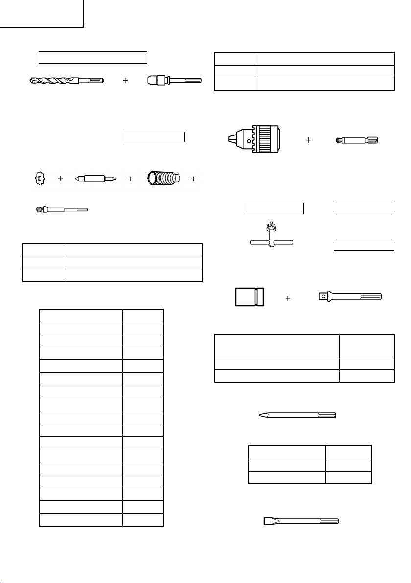
1. Through-hole drilling (Rotation + Hammering)
(1) Drill bit (SDS-max shank)
External dia. Overall lenght Code No.
13-3/8"
5/8" (340 mm)
(16 mm) 21-1/4"
(540 mm)
13-3/8"
3/4" (340 mm)
(19 mm) 21-1/4"
(540 mm)
313448
313456
313449
313457
External dia. Overall lenght Code No.
12-5/8"
7/8" (320 mm)
(22 mm) 20-15/32"
(520 mm)
12-5/8"
1" (320 mm)
(25 mm) 20-15/32"
(520 mm)
14-9/16"
1-1/8" (370 mm)
(28 mm) 22-7/16"
(570 mm)
14-9/16"
1-1/4" (370 mm)
(32 mm) 22-7/16"
(570 mm)
14-9/16"
1-1/2" (370 mm)
(38 mm) 22-7/16"
(570 mm)
313450
313458
313451
313459
313452
313460
313453
313461
313454
313462
13
Page 14
English
2. Anchor hole drilling (Rotation + Hammering)
Adaptor for SDS-plus shank bit
Code No. Core bit size
313466 1-3/8" (35 mm) or below
313467 1-1/2" (38 mm) or above
(1) Drill Bit (2) Adaptor for SDS-plus
4. Drilling holes....For drilling metals and wooden
(SDS-plus shank) shank bit
(SDS max shank)
Code No. 313465
3. Large-dia. hole boring (Rotation + Hammering)
(1)
(2)
(3)
(1) Center pin
Code No. Core bit size
956009 1-1/4" (32 mm) and 1-3/8" (35 mm)
5. Bolt plaching operation with Chemical Anchor
955165 1-1/2" (38 mm) or above
(2) Core bit (with guide plate)
External dia. Code No.
1" (25 mm) 955994*
1-1/8" (29 mm) 955995*
1-1/4" (32 mm) 955996
1-3/8" (35 mm) 955998
1-1/2" (38 mm) 956000
1-3/4" (45 mm) 955154
2" (50 mm) 985380
6. Demolishing (Hammering)
2-1/8" (54 mm) 955155
2-1/2" (64 mm) 956002
2-9/16" (65 mm) 987009
3-1/8" (79 mm) 955157
3-5/32" (80 mm) 987010
3-17/32" (90 mm) 987011
3-11/16" (94 mm) 956004
3-15/16" (100 mm) 987012
7. Groove digging and edging (Hammering)
4-1/8" (105 mm) 955159
*without guide plate
(3) Core bit shank (SDS max shank)
materials
(1) 13mm drill chuck (2) Chuck adaptor
(13VLD-D) (SDS max shank)
(with chuck wrench)
Code No. 321813 Code No. 313468
(3) Chuck wrench
Code No. 930515
(Rotation + Hammering)
(Standard socket
on the market)
Square dimensions of the side
of the socket installation
(1) Chemical Anchor Adaptor
(SDS max shank)
Code No.
1/2" (12.7 mm) 313469
3/4" (19.0 mm) 313470
(1) Bull point
Overall length Code No.
11" (280 mm) 313471
15-3/4" (400 mm) 313472
14
Page 15
English
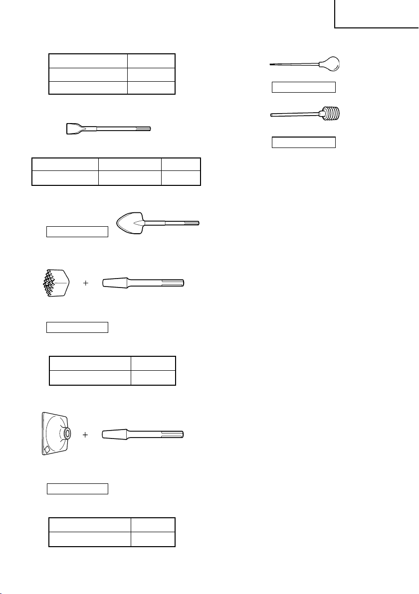
(1) Cold chisel
Overall length Code No.
11" (280 mm) 313473
15-3/4" (400 mm) 313474
8. Asphalt cutting (Hammering)
(1) Cutter
Overall length Width Code No.
15-3/4" (400 mm) 1-31/32" (50 mm) 313475
9. Digging
(1) Scoop
Code No. 313476
10. Surface Roughing (Hammering)
(1) Bushing Tool
Code No. 313477
12. Syringe (for chip removal)
Code No. 320859
Code No. 318085
13. Hammer grease A
1.1 lbs (500 g) (in a can) Code No. 980927
0.15 lbs (70 g) (in a green tube) Code No. 308471
0.07 lbs (30 g) (in a green tube) Code No. 981840
NOTE:
Specifications are subject to change without any
obligation on the part of the HITACHI.
2) Shank
Overall length Code No.
8-21/32" (220 mm) 313479
11. Tamping (Hammering)
(1) Rammer
Code No. 313478
(2) Shank
Overall length Code No.
8-21/32" (220 mm) 313479
15
Page 16

Français
INFORMATIONS IMPORTANTES DE SÉCURITÉ
Lire et comprendre toutes les précautions de sécurité, les avertissements et les instructions de fonctionnement
dans ce mode d’emploi avant d’utiliser ou d’entretenir cet outil motorisé.
La plupart des accidents causés lors de l’utilisation ou de l’entretien de l’outil motorisé proviennent d’un non
respect des règles ou précautions de base de sécurité. Un accident peut la plupart du temps être évité si l’on
reconnaît une situation de danger potentiel avant qu’elle ne se produise, et en observant les procédures de sécurité
appropriées.
Les précautions de base de sécurité sont mises en évidence dans la section “SECURITE” de ce mode d’emploi et
dans les sections qui contiennent les instructions de fonctionnement et d’entretien.
Les dangers qui doivent être évités pour prévenir des blessures corporelles ou un endommagement de la machine
sont identifiés par AVERTISSEMENTS sur l’outil motorisé et dans ce mode d’emploi.
NE JAMAIS utiliser cet outil motorisé d’une manière qui n’est pas spécifiquement recommandée par HITACHI.
SIGNIFICATION DES MOTS D’AVERTISSEMENT
AVERTISSEMENT indique des situations potentiellement dangereuses qui, si elles sont ignorées, pourraient
entraîner la mort ou de sérieuses blessures.
PRECAUTION indique des situations dangereuses potentilles qui, si elles ne sont pas évitées, peuvent entraîner
de mineures et légères blessures ou endommager la machine.
REMARQUE met en relief des informations essentielles.
SECURITE
AVERTISSEMENTS DE SÉCURITÉ GÉNÉRAUX CONCERNANT LES OUTILS ÉLECTRIQUES
AVERTISSEMENT :
Lire tous les avertissements de sécurité et les instructions
Tout manquement à observer ces avertissements et instructions peut engendrer des chocs électriques, des
incendies et/ou des blessures graves.
Conservez tous les avertissements et toutes les instructions pour vous y référer ultérieurement.
Le terme "outil électrique", utilisé dans les avertissements, se réfère aux outils électriques (câblé) ou aux
outils à piles (sans fil).
1) Sécurité de l’aire de travail
a) Maintenir l'aire de travail propre et bien
éclairée.
Les endroits encombrés ou sombres sont
propices aux accidents.
b) Ne pas utiliser d'outils électriques en présence
de liquides, gaz ou poussière inflammables,
au risque de provoquer une explosion.
Les outils électriques créent des étincelles
susceptibles d'enflammer la poussière.
c) Ne pas laisser les enfants et les visiteurs
s'approcher de vous lorsque vous utiliser un
outil électrique.
Les distractions peuvent faire perdre le contrôle.
2) Sécurité électrique
a) Les prises de l'outil électrique doivent
correspondre à la prise secteur.
Ne jamais modifier la prise.
Ne pas utiliser d'adaptateurs avec les outils
électriques mis à la masse.
Les prises non modifiées et les prises secteurs
correspondantes réduisent les risques de
choc électrique.
b) Eviter tout contact avec les surfaces mises à
la masse telles que les tuyaux, radiateurs,
bandes et réfrigérateurs.
Le risque de choc électrique est accru en cas
de mise à la masse du corps.
c) Ne pas exposer les outils électriques à la pluie
ou à des conditions humides.
Si l'eau pénètre dans l'outil, cela augmente
les risques de choc électrique.
d) Ne pas utiliser le cordon à tort. Ne jamais
utiliser le cordon pour transporter ou
débrancher l'outil électrique.
Maintenir le cordon loin de la chaleur, de
l'huile, des bords pointus ou des pièces
mobiles.
Les cordons endommagés ou usés
augmentent les risques de choc électrique.
16
Page 17

Français
e) En cas d'utilisation d'un outil électrique à
l'extérieur, utiliser un cordon de rallonge
adapté à un usage extérieur.
L'utilisation d'un cordon adapté à l'usage
extérieur réduit les risques de choc électrique.
f) Si vous devez utiliser un outil électrique dans
un endroit humide, utilisez une alimentation
protégée contre les courants résiduels.
L'utilisation d'un dispositif de protection
contre les courants résiduels réduit le risque
de choc électrique.
3) Sécurité personnelle
a) Restez alerte, regarder ce que vous faites et
usez de votre bon sens en utilisant un outil
électrique.
Ne pas utiliser d'outil électrique si vous êtes
sous l'influence de drogues, d'alcool ou de
médicaments.
Pendant l'utilisation d'outils électrique, un
instant d'inattention peut entraîner des
blessures graves.
b) Utiliser un équipement de protection
individuelle. Toujours porter des verres de
protection.
L'utilisation d'équipements de protection tels
que les masques anti-poussière, les chaussures
de sécurité anti-dérapantes, les casques ou les
protections auditives dans des conditions
appropriées réduisent les risques de blessures.
c) Empêcher les démarrages intempestifs.
Veiller à ce que l'interrupteur soit en position
d'arrêt avant de brancher à une source
d'alimentation et/ou une batterie, de
ramasser l'outil au sol ou de le transporter.
Transporter les outils électriques avec le doigt
sur l'interrupteur ou brancher les outils
électriques avec l'interrupteur en position de
marche peut entraîner des accidents.
d) Retirer toute clé de sécurité ou clé avant de
mettre l'outil électrique en marche.
Laisser une clé ou une clé de sécurité sur une
partie mobile de l'outil électrique peut
engendrer des blessures.
e) Ne pas trop se pencher. Toujours garder une
bonne assise et un bon équilibre pendant le
travail.
Cela permet un meilleur contrôle de l'outil
électrique dans des situations imprévisibles.
f) Porter des vêtements adéquats. Ne pas
porter de vêtements amples ni de bijoux.
Maintenir les cheveux, les vêtements et les
gants loin des pièces mobiles.
Les vêtements amples ou les cheveux longs
peuvent se prendre dans les pièces mobiles.
g) En cas de dispositifs destinés au
raccordement d'installations d'extraction et
de recueil de la poussière, veiller à ce qu'ils
soient correctement raccordés et utilisés.
L'utilisation d'un dispositif de collecte de la
poussière peut réduire les dangers associés
à la poussière.
4) Utilisation et entretien d'un outil électrique
a) Ne pas forcer sur l'outil électrique. Utiliser
l'outil électrique adapté à vos travaux.
Le bon outil électrique fera le travail mieux et
en toute sécurité au régime pour lequel il a
été conçu.
b) Ne pas utiliser l'outil électrique si
l'interrupteur ne le met pas en position de
marche et d'arrêt.
Tout outil ne pouvant être contrôlé par
l'interrupteur est dangereux et doit être réparé.
c) Débrancher la prise ou retirer la batterie avant
de procéder à des réglages, au remplacement
des accessoires ou au stockage des outils
électriques.
Ces mesures préventives de sécurité
réduisent les risques de démarrage accidentel
de l'outil électrique.
d) Stockez les outils électriques inutilisés hors
de la portée des enfants et ne pas laisser des
personnes non familiarisées avec l'outil ou
ces instructions utiliser l'outil électrique.
Les outils électriques sont dangereux entre
les mains d'utilisateurs non habilités.
e) Entretenir les outils électriques. Vérifier
l'absence de mauvais alignement ou d'arrêt,
d'endommagement de pièces ou toute autre
condition susceptible d'affecter l'opération de
l'outil.
Si l'outil est endommagé, le faire réparer
avant utilisation.
De nombreux accidents sont dus à des outils
mal entretenus.
f) Maintenir les outils coupants aiguisés et
propres.
Des outils coupants bien entretenus avec des
bords aiguisés sont moins susceptibles de se
coincer et plus simples à contrôler.
g) Utiliser l'outil électrique, les accessoires et
les mèches de l'outil, etc. conformément à
ces instructions en tenant compte des
conditions d'utilisation et du travail à réaliser.
L'utilisation de l'outil électrique pour des
opérations différentes de celles pour
lesquelles il a été conçu est dangereuse.
5) Service
a) Faire entretenir l'outil électrique par un
technicien habilité à l'aide de pièces de
rechange identiques exclusivement.
Cela garantira le maintien de la sécurité de
l'outil électrique.
17
Page 18

Français
AVERTISSEMENTS DE SÉCURITÉ DU
12. Maintenir toutes les vis, tous les boulons et les
MARTEAU ROTATIF
1. Porter des protections anti-bruit.
L’exposition au bruit peut engendrer
une perte de l’audition.
2. Utilisez les poignées auxiliaires, si fourni avec
l’outil.
13. Ne pas utiliser les outils motorisés si le revêtement
14. Les lames et les accessoires doivent être
Toute perte de contrôle peut entraîner des
blessures.
3. Tenir les outils électriques par les surfaces de
grippage lors de la réalisation d’opération où l’outil
de coupe risque d’entrer en contact avec des
câbles cachés ou son propre cordon. Le contact
15. Garder propres les évents d’air du moteur.
d’un outil de coupe avec un fil “sous tension”
risque de mettre les parties métalliques de l’outil
“sous tension” d’électrocuter l’utilisateur.
4. NE JAMAIS toucher la mèche avec des mains nues
après l’utilisation.
16. Utiliser l’outil motorisé à la tension nominale.
5. NE JAMAIS porter de gants faits d’une matière qui
risque de s’enrouler, comme du coton, de la laine,
de la toile ou de la ficelle, etc.
6. TOUJOURS fixer la poignée latérale et tenir
fermement le marteau rotatif.
7. NE JAMAIS toucher les parties mobiles.
NE JAMAIS placer ses mains, ses doigts ou toute
autre partie de son corps près des parties mobiles
17. NE JAMAIS utiliser un outil défectueux ou qui
de l’outil.
8. NE JAMAIS utiliser l’outil sans que tous les
dispositifs de sécurité ne soient en place.
NE JAMAIS faire fonctionner cet outil sans que
tous les dispositifs et caractéristiques de sécurité
ne soient en place et en état de fonctionnement.
Si un entretien ou une réparation nécessite le
18. NE JAMAIS laisser fonctionner l’outil sans
retrait d’un dispositif ou d’une caractéristique de
sécurité, s’assurer de bien remettre en place le
dispositif ou la caractéristique de sécurité avant
de recommencer à utiliser l’outil.
19. Manipuler l’outil motorisé avec précaution.
9. Utiliser l’outil correct
Ne pas forcer sur un petit outil ou accessoire pour
faire le travail d’un outil de grande puissance. Ne
pas utiliser un outil pour un usage pour lequel il
20. Ne pas essuyer les parties en plastique avec du
n’a pas été prévu: par exemple, ne pas utiliser une
scie circulaire pour couper des branches d’arbre
ou des bûches.
10. NE JAMAIS utiliser un outil motorisé pour des
applications autres que celles spécifiées.
NE JAMAIS utiliser un outil motorisé pour des
applications autres que celles spécifiées dans le
mode d’emploi.
11. Manipuler l’outil correctement
Utiliser l’outil de la façon indiquée dans ce mode
d’emploi. Ne pas laisser tomber ou lancer l’outil.
NE JAMAIS permettre que l’outil soit utilisé par
des enfants, des personnes non familiarisées avec
son fonctionnement ou un personnel non autorisé.
18
couvercles fermement en place.
Maintenir toutes les vis, tous les boulons et les
couvercles fermement montés. Vérifier leurs
conditions périodiquement.
de plastique ou la poignée est fendu.
Des fentes dans le revêtement ou la poignée
peuvent entraîner une électrocution. De tels outils
ne doivent pas être utilisés avant d’être réparé.
fermement montés sur l’outil.
Eviter les blessures potentielles personnelles et
aux autres. Les lames, les instruments de coupe
et les accessoires qui ont été montés sur l’outil
doivent être fixés et serrés fermement.
Les évents d’air du moteur doivent être maintenus
propres de façon que l’air puisse circuler librement
tout le temps. Vérifier les accumulations de
poussière fréquemment.
Utiliser l’outil motorisé à la tension spécifiée sur
sa plaque signalétique.
Si l’on utilise l’outil motorisé avec une tension
supérieure à la tension nominale, il en résultera
une rotation anormalement trop rapide du moteur
et cela risque d’endommager l’outil et le moteur
risque de griller.
fonctionne anormalement.
Si l’outil n’a pas l’air de fonctionner normalement,
fait des bruits étranges ou sans cela paraît
défectueux, arrêter de l’utiliser immédiatement et
le faire réparer par un centre de service Hitachi
autorisé.
surveillance. Le mettre hors tension.
Ne pas abandonner l’outil avant qu’il ne soit
complètement arrêté.
Si un outil motorisé tombe ou frappe un matériau
dur accidentellement, il risque d’être déformé,
fendu ou endommagé.
solvant.
Les solvants comme l’essence, les diluants, la
benzine, le tétrachlorure de carbone et l’alcool
peuvent endommager et fissurer les parties en
plastique. Ne pas les essuyer avec de tels solvants.
Essuyer les parties en plastique avec un chiffon
doux légèrement imbibé d’une solution d’eau
savonneuse et sécher minutieusement.
Page 19

Français
21. TOUJOURS porter des lunettes de protection qui
respectent les dernières révisions du
Standard ANSI Z87.1.
22. TOUJOURS vérifier s’il y a des objets encastrés,
par exemple des fils électriques. Le fait de toucher
avec l’outil un fil ou un câble électrique sous
tension risque de provoquer une décharge
électrique.
Avant l’utilisation, vérifier s’il y a des objets
dissimulés, par exemple des câbles électriques,
dans le mur, le plancher ou le plafond.
SYMBOLES
Définitions pour les symboles utilisés sur cet outil
V ................ volts
Hz .............. hertz
A ............... ampères
no .............. vitesse sans charge
W .............. watt
............. Construction de classe II
---/min ....... tours par minute
............. Courant alternatif
DOUBLE ISOLATION POUR UN
FONCTIONNEMENT PLUS SUR
Pour assurer un fonctionnement plus sûr de cet outil
motorisé, HITACHI a adopté une conception à double
insolation. “Double isolation” signifie que deux
systèmes d’isolation physiquement séparés ont été
utilisés pour isoler les matériaux conducteurs
d’électricité connectés à l’outil motorisé à partir du cadre
extérieur manipulé par l’utilisateur. C’est pourquoi, le
symbole “ ” ou les mots “Double insulation” (double
isolation) apparaissent sur l’outil motorisé ou sur la
plaque signalétique.
Bien que ce système n’ait pas de mise à terre extérieure,
il est quand même nécessaire de suivre les précautions
de sécurité électrique données dans ce mode d’emploi,
y-compris de ne pas utiliser l’outil motorisé dans un
environnement humide.
Pour garder le système de double isolation effectif,
suivre ces précautions:
䡬
䡬
Seuls les CENTRES DE SERVICE AUTORISES
HITACHI peuvent démonter et remonter cet outil
motorisé et uniquement des pièces de rechange
HITACHI garanties d’origine doivent être utilisées.
Nettoyer l’extérieur de l’outil motorisé uniquement
avec un chiffon doux légèrement imbibé d’une
solution savonneuse et essuyer minutieusement.
Ne jamais utiliser des solvants, de l’essence ou des
diluants sur les parties en plastique; sinon le
plastique risquerait de se dissoudre.
CONSERVER CES INSTRUCTIONS
ET
LES METTRE A LA DISPOSITION DES AUTRES UTILISATEURS
ET
PROPRIETAIRES DE CET OUTIL!
19
Page 20

Français
DESCRIPTION FONCTIONNELLE
REMARQUE:
Les informations contenues dans ce mode d’emploi sont conçues pour assister l’utilisateur dans une utilisation
sans danger et un entretien de l’outil motorisé.
NE JAMAIS utiliser ni entreprendre une révision de l’outil sans avoir d’abord lu et compris toutes les
instructions de sécurité contenues dans ce manuel.
Certaines illustrations dans ce mode d’emploi peuvent montrer des détails ou des accessoires différents de
ceux de l’outil motorisé utilisé.
NOM DES PARTIES
Attache coulissante
Capuchon avant
Foret de perçage
Poignée latérale
Carter
Couvercle de queue
Vis de fixation
(Sous le couvercle
de queue)
Fig. 1
SPECIFICATIONS
Moteur Moteur série monophasé à collecteur
Source d’alimentation Secteur, 120 V 60 Hz, monophasé
Courant 8.4 A
Capacité Mèche: 1-1/2" (38 mm)
Couronne: 4-13/64" (105 mm)
Vitesse sans charge 620/min.
Vitesse de percussion à pleine charge 2,800/min.
Poids 14.1 lbs (6.4 kg)
Sélecteur
Interrupteur
Poignée
Plaque
signalétique
Bouchon de charbon
(À l’intérieur du
couvercle de queue)
20
Page 21

ASSEMBLAGE ET FONCTIONNEMENT
Français
APPLICATIONS
Fonction de rotation et de percussion
䡬
Perçage de trous d’ancrage
䡬
Fonction de percussion uniquement
AVANT L’UTILISATION
1. Source d’alimentation
2. Interrupteur d’alimentation
3. Cordon prolongateur
4. Vérifier la prise
5. Vérification des conditions d’environnement
6. Comment installer l’outil
Perçage de trous dans béton
䡬
Démollition du béton, burinage, creusage et
équarrissage (avec installation des
accessoires en option)
S’assurer que la source d’alimentation qui doit être
utilisée est conforme à la source d’alimentation
requise spécifiée sur la plaque signalétique du
produit.
S’assurer que l’interrupteur est sur la position OFF
(arrêt). Si la fiche est connectée sur une prise alors
que l’interrupteur est sur la position ON (marche),
l’outil motorisé démarrera immédiatement
risquant de causer de sérieuses blessures.
Quand la zone de travail est éloignée de la source
d’alimentation, utiliser un cordon prolongateur
d’épaisseur et de capacité nominale suffisante. Le
cordon prolongateur doit être aussi court que
possible.
AVERTISSEMENT:
Tout cordon endommagé devra être
remplacé ou réparé.
Si la prise reçoit la fiche avec beaucoup de jeu,
elle doit être réparée. Contacter un électricien
licencié pour réaliser les réparations nécessaires.
Si une telle prise défectueuse est utilisée, elle peut
causer une surchauffe entraînant des dangers
sérieux.
Vérifier que l’état de l’aire de travail est conforme
aux précautions.
(2) Pour fixer l’outil (tige SDS max), l’insérer dans
(3) Tirer sur l’outil pour s’assurer qu’il est bien
(4) Pour retirer l’outil, tirer complètement l’attache
UTILISATION
1. Comment percer des trous (Fig. 3)
(1) Tirer l’interrupteur après avoir appliqué la pointe
(2) Il n’est pas nécessaire d’appuyer de force sur le
l’orifice jusqu’à ce qu’il touche l’extrémité
intérieure de l’orifice comme indiqué sur la Fig. 2.
Si l’on continue à tourner l’outil en exerçant une
légère pression, l’on sentira un endroit où il y a un
obstacle. A cet endroit, tirer l’attache coulissante
dans le sens de la flèche et insérer l’outil à fond
jusqu’à ce qu’il touche l’extrémité intérieure.
Le fait de relâcher l’attache coulissante l’inverse
et fixe l’outil en place.
Capuchon avant
Elément de la
Outil
tige SDS max
Fig. 2
verrouillé à fond.
coulissante dans le sens de la flèche et sortir l’outil.
REMARQUE:
Vérifier que le boulon à oreilles dans la poignée
latérale est bien serré avant d'utiliser l'outil.
de la mèche à la position de forage.
corps du marteau rotatif. Il sera suffisant d’appuyer
légèrement sur le marteau rotatif jusqu’à ce que
les éclats soient déchargés librement.
Poignée latérale
Attache
coulissante
PRECAUTION:
Pour les outils tels que foret et pointe de broyage
n’utiliser que les pièces HITACHI authentiques.
(1) Nettoyer, puis graisser la queue de l'outil avec la
graisse ou l'huile.
PRECAUTION:
Bien que cette machine soit équipée d’un cran de
sécurité, si la mèche est prise dans le béton ou
autre matériel l’arrêt de son fonctionnement
pourrait faire tourner le corps de la machine. Tenir
fermement la poignée principale et la poignée
latérale pendant le fonctionnement.
Fig. 3
21
Page 22

Français
2. Comment buriner ou démanteler (Fig. 4)
En appliquant la pointe de la mèche sur la poition
de burinage ou de démantelage, faire fonctionner
le marteau perforateur en utilisant son propre poids.
Il n’est pas nécessaire d’appuyer ou de pousser de
force.
Fig. 4
3. Perçage en “rotation + percussion”:
PRECAUTION:
Si l’on règle le sélecteur pendant la rotation du
moteur, l’outil risque de se mettre brusquement
en marche et de provoquer des blessures
inattendues. Bien régler le sélecteur lorsque le
moteur est à l’arrêt complet.
(1) Commutation sur “rotation + percussion”
(a) Appuyer sur le bouton, libérer le verrou et
tourner le levier de sélection dans le sens des
aiguilles d’une montre.
(b) Aligner ▲ du levier de sélection sur du
support de levier comme indiqué sur la Fig. 5.
(c) Relâcher le bouton pour verrouiller le levier
de sélection.
Cache inférieur
4. Burinage et découpures en “percussion”:
PRECAUTION:
Si l’on règle le sélecteur pendant la rotation du
䡬
moteur, l’outil risque de se mettre brusquement
en marche et de provoquer des blessures
inattendues. Bien régler le sélecteur lorsque le
moteur est à l’arrêt complet.
䡬
Si l’on utilise une pointe à béton ou un ciseau à
froid sur la position “rotation + percussion”, l’outil
risque de se mettre brusquement en marche et
de provoquer des blessures inattendues. Bien
veiller à les utiliser sur la position “percussion”.
(1) Commutation sur “percussion”
(a) Appuyer sur le bouton, libérer le verrou et
tourner le levier de sélection dans le sens
inverse des aiguilles d’une montre.
(b) Aligner ▲ du levier de sélection sur du
support de levier comme indiqué sur la Fig. 6.
(c) Relâcher le bouton pour verrouiller le levier
de sélection.
Sélecteur
Cache inférieur
Bouton
Fig. 6
REMARQUE:
Tourner le sélecteur (ne pas appuyer dessus) pour
voir s’il est bien verrouillé à fond et s’assurer qu’il
ne tourne pas.
Bouton
Sélecteur
Fig. 5
REMARQUE:
Tourner le sélecteur (ne pas appuyer dessus) pour
voir s’il est bien verrouillé à fond et s’assurer qu’il
ne tourne pas.
22
(2) Pour fixer la position de travail d’outils tels que
ciseau à froid, etc.
(a) Appuyer sur le bouton, libérer le verrou et
tourner le levier de sélection dans le sens
inverse des aiguilles d’une montre.
Aligner ▲ du levier de sélection sur du
support de levier comme indiqué sur la Fig. 7.
(b) Relâcher le bouton pour verrouiller le levier
de sélection.
Page 23

Français
Bouton
Sélecteur
Cache inférieur
Fig. 7
(c) Turn the grip as illustrated in Fig. 8 and fix
the tool to the desired working direction.
Attache coulissante
Fig. 8
(d) Commuter le sélecteur sur “frappe” en
procédant comme indiqué au point (1) cidessus et fixer la position de l’outil.
5. Préchauffage (Fig. 9)
Le système de graissage de l’outil risque de devoir
être préchauffé dans les régions froides.
Placer l’extrémité de la mèche de façon qu’elle
entre en contact avec le béton, enclencher
l’interrupteur et effectuer une opération de
préchauffage. Bien s’assurer que l’outil fait
entendre un bruit de heurt, puis utiliser l’outil.
6. Comment utiliser la mèche (queue conique) et le
raccord de queue conique.
(1) Installer la mèche à queue conique dans le raccord
de queue conique. (Fig. 10)
Raccord de queue
coníque
Mèche
(Queue
conique)
Fig. 10
(2) Mettre l’appareil sous tension et percer un trou de
base.
(3) Après avoir retirer la poussière avec une seringue,
fixer le mandrin à la pointe du sabot et l’enfoncer
dans le sabot avec un marteau.
(4) Pour retirer la mèche à queue conique, insérer une
clavette dans la fente du raccord de queue conique
et frapper sur la clavette avec un marteau. (Fig.
11)
Taper shank
Cotter
adaptor
Support
Fig. 11
UTILISATION DU MANDRIN PORTE-FORET
ET DU RACCORD DE MANDRIN
Noter que l’appareil peut fonctionner en “rotation
seulement” si l’on y monte des pièces vendues
séparément, par exemple mandrin porte-foret et raccord
de mandrin. L’utiliser avec le levier sur la position
“rotation + percussion”.
AVERTISSEMENT:
Pendant le fonctionnement, bien tenir la poignée
Fig. 9
et la poignée latérale pour éviter que le corps de
l’opérateur n’oscille.
PRECAUTIÓN:
Pendant l’opération de préchauffage, tenir
fermement la poignée latérale et le corps de l’outil
des deux mains de façon à garder une bonne prise
de l’outil et faire attention que le corps de
(1) Commutation sur “rotation + percussion”
Pour commuter sur “rotation + percussion”,
procéder comme indiqué au point [3. Perçage en
“rotation + percussion”].
l’opérateur ne pivote pas sons l’effet d’une mèche
coincée.
23
Page 24

Français
(2) Fixation du raccord de mandrin sur le mandrin
porte-foret (Fig. 12)
(a) Fixer le raccord de mandrin sur le mandrin
porte-foret.
(b) La tige SDS max du raccord de mandrin est
l’équivalent du foret de perçage. En
conséquence, pour la fixation et le retrait,
procéder comme indiqué au point [Fixation
des outils].
Capuchon avant
Mandrin
porte-foret
Tige SDS max
Raccord de
mandrin
Attache
coulissante
(2) Monter la queue de couronne sur le marteau rotatif
à percussion. (Fig. 14)
Fig. 12
(3) Perçage
(a) Le perçage ne s’effectuera pas plus
rapidement si l’on exerce une pression plus
forte que nécessaire sur le corps de l’outil.
Au contraire, le fait d’appuyer plus fort ou
d’exercer une plus forte pression sur le corps
de l’outil ne peut qu’endommager le foret de
perçage, réduisant le rendement et la durée
de service de l’outil.
(b) Il peut arriver que le foret se rompe lorsque
le perçage est presque terminé. Il est
important de relâcher la pression de la
poussée lorsqu’on arrive vers la fin du
perçage.
(3) Introduire la guijon central dans la plaque de
guidage jusqu’à ce qu’il arrête.
(4) Engager la plaque de guidage dans la couronne et
tourner la plaque de guidage à gauche ou à droite
de manière à ce qu’elle à ce qu’elle ne puisse pas
COMMENT UTILISER LA COURONNE
tomber, même si elle orientée vers le bas. (Fig. 15)
Utiliser la couronne pour percer de grands trous.
L’utiliser avec le goujon central et la queue de couronne
fournis en tant qu’accessoires en option.
1. Montage
PRECAUTION:
S’assurer que l’interrupteur est sur la position
Goujon central
Couronne
d’arrêt (OFF) et débrancher l’outil.
Couronne
Queue de
couronna
Fig. 13
Fig. 14
Plaque de
guidage
Bout de
couronne
(1) Monter la couronne sur la queue de couronne. (Fig.
13)
Graisser le filetage da la queue de couronne afin
de faciliter le démontage.
2. Perçage (Fig. 16)
(1) Brancher la perceuse.
(2) Un ressort est placé dans le goujon central.
Appuyer légèrement l’outil contre le mur ou le
plancher tout droit. Toute la surface de la couronne
doit être en contact avec le mur ou le plancher.
Mettre en marche.
24
Fig. 15
Page 25

Français
(3) Quand on a percé sur une profondeur d’environ
3/16" (5 mm), la position du trou est déterminée.
Continuer à percer après avoir retiré le goujon
central et la plaque de guidage de la couronne.
(4) Si l’on applique une force excessive, cela donnera
un travail bâclé et abîmera la pointe du foret de
perçage, réduisant ainsi la durée de service du
marteau rotatif.
Fig. 16
PRECAUTION:
Quand on retire le goujon central et la plaque de
guidage, mettre l’interrupteur sur la position
d’arrêt (OFF) et débrancher la perceuse.
3. Démontage (Fig. 17)
Une autre méthode consiste à retirer la queue de
la couronne du marteau rotatif à frapper fortement
la tête de la queue de la couronne deux ou trois
fois avec un marteau, tout en maintenant la
couronne. Cela aura pour effet de desserrer le
filetage et on pourra retirer la couronne.
Queue de
couronne
Fig. 17
ENTRETIEN ET INSPECTION
AVERTISSEMENT:
S’assurer de mettre l’interrupteur d’alimentation sur la position OFF et de déconnecter la fiche de la prise
secteur avant l’entretien et l’inspectio.
1. Contrôle du foret de perçage
Etant donné que l’utilisation d’une mèche usée
entraînera un mauvais fonctionnement du moteur
et une diminution de l’efficacité, remplacez la
mèche usée par une neuve ou aiguisez-la
immédiatement et dès que vous notez une certaine
usure.
2. Inspection des vis
Inspecter régulièrement toutes les vis et s’assurer
qu’elles sont correctement serrées. Si l’une des vis
était desserrée, la resserrer immédiatement.
AVERTISSEMENT:
Utiliser la marteau rotatif avec des vis desserrées
est extrêmement dangereux.
de la “limite d’usure”, il pourra en résulter un
mauvais fonctionnement du moteur. Quand le
moteur est équipé d’un balai en carbone à arrêt
automatique, il s’arrêtera automatiquement.
Remplacez alor les balais en carbone par des
nouveaux et ayant les mêmes numéros que ceux
montré sur la figure. En outre, toujours tenir les
balais propres et veiller à ce qu’ils coulissent
librement dans les supports.
PRECAUTION:
Utiliser la polisseuse avec un balai en carbone qui
est usé au-delà de la limite d’usure endommagera
le moterur.
3. Entretien du moteur:
Le bobinage de l’ensemble moteur est le “coeur”
même de l’outil électro-portatif. Veiller
soigneusement à ce que ce bobinage ne soit pas
endommagé et/ou mouillé par de l’huile ou de
l’eau.
4. Contrôle des balais en carbone (Fig. 18)
Le moteur utilise des balais en carbone qui sont
des pièces qui s’usent. Quand ils sont usés ou près
25
Page 26

Français
Limite d’usure
No. du balai en carbone
74
0.28" (7 mm)
0.67" (17 mm)
Fig. 18
REMARQUE:
Utiliser le balai en carbone HITACHI No. 74 indiqué
sur la Fig. 18.
䡬
Remplacement du balais en carbone
Desserrer la vis de fixation et enlever le couvercle
de la queue. Enlever la chapeau de balai et la balai
en carbone. Après avoir remplacé le balai en
carbone, serrer fermement le chapeau du balai et
installer le couvercle avec deux vis de fixation.
5. Comment remplacer la graisse
Cette machine est de contruction entièrement
hermétique pour la protéger contre la poussière
et pour éviter les fuites de lubrifiant. Elle peut donc
être utilisée sans lubrification pendant longtemps.
Remplacer la graisse comme indiqué ci-dessous.
䡬
Période de remplacement
Remplacer la graisse après chaque période de 6
moins d’utilisation. Se procurer la graisse chez
l’Agence de Service Autorisée HITACHI la plus
proche. Procéder au remplacement.
䡬
Plein de graisse
PRECAUTION:
Avant de faire le plein de la graisse, fermer
l’interrupteur et débrancher l’outil de la prise de
courant.
REMARQUE:
La graisse pour marteau électrique Hitachi A est
du type à viscosité faible. Si nécessaire, se procurer
la graisse chez un agent réparateur Hitachi agréé;
adressez-vous à votre Agent de Service Autorisé
Hitachi pour vous en procurer de nouveau.
6. Entretien et reparation
Tous les outils motorisés de qualité auront
éventuellement besoin d’une réparation ou du
remplacement d’une pièce à cause de l’usure
normale de l’outil. Pour assurer que seules des
pièces de rechange autorisées seront utilisées, tous
les entretiens et les réparations doivent être
effectués uniquement par UN CENTRE DE SERVICE
HITACHI AUTORISE.
7. Liste des pièces de rechange
PRECAUTION :
Les réparations, modifications et inspections des
●
outils électriques Hitachi doivent être confiées à
un service après-vente Hitachi agréé.
Il sera utile de présenter cette liste de pièces au
service après-vente Hitachi agréé lorsqu’on
apporte un outil nécessitant des réparations ou
tout autre entretien.
Lors de l’utilisation et de l’entretien d’un outil
électrique, respecter les règlements et les normes
de sécurité en vigueur dans le pays en question.
MODIFICATIONS :
Les outils électriques Hitachi sont constamment
améliorés et modifiés afin d’incorporer les tous
derniers progrès technologiques.
En conséquence, il est possible que certaines
pièces soient modifiées sans avis préalable.
(1) Enlever le couvercle du carter et essuyer la graisse
à l’intérieur. (Fig. 19)
(2) Appliquer 2.0 oz (60 g) de graisse pour marteau
électrique Hitachi A (en tube) au carter.
(3) Après avoir fait le plein de graisse, installer
fermement le couvercle du carter.
Cache de carter
Fig. 19
26
Page 27

Français
ACCESSOIRES
AVERTISSEMENT:
TOUJOURS utiliser UNIQUEMENT des pièces de rechange et des accessoires HITACHI. Ne jamais utiliser de
pièce de rechange ou d’accessoires qui ne sont pas prévus pour être utilisé avec cet outil. En cas de doute,
contacter HITACHI pour savoir si une pièce de rechange ou un accessoire particulier peuvent être utilisés en
toute sécurité avec votre outil.
L’utilisation de tout autre attachement ou accessoire peut être dangereux et peut causer des blessures ou
des dommages mécaniques.
REMARQUE:
Les accessoires sont sujets à changement sans obligation de la part de HITACHI.
ACCESSOIRES STANDARD
(1) Valise (Plastique) (No. de code 326489).............. 1
(2) Poignée latérale (No. de code 313078) ............... 1
ACCESSOIRES SUR OPTION.....vendus
séparément
Pour plus d’informations sur les accessoires, veuillez
contacter HITACHI 1-800-59-TOOLS
1. Perçage de trous de passage (Rotation +
Percussion)
(1) Mèche (Tige SDS max)
Diamètre extérieur
5/8" (340 mm)
(16 mm) 21-1/4"
3/4" (340 mm)
(19 mm) 21-1/4"
7/8" (320 mm)
(22 mm) 20-15/32"
1" (320 mm)
(25 mm) 20-15/32"
1-1/8" (370 mm)
(28 mm) 22-7/16"
Longueur totale No. de code
13-3/8"
(540 mm)
13-3/8"
(540 mm)
12-5/8"
(520 mm)
12-5/8"
(520 mm)
14-9/16"
(570 mm)
313448
313456
313449
313457
313450
313458
313451
313459
313452
313460
Diamètre extérieur
1-1/4" (370 mm)
(32 mm) 22-7/16"
1-1/2" (370 mm)
(38 mm) 22-7/16"
2. Perçage de trous d’ancrage (Rotation + Percussion)
Adaptateur pour tige SDS plus
(1) Mèche
3. Perçage de trous à large diamètre (Rotation +
Percussion)
(1) Goujon central
No. de code
956009 1-1/4" (32 mm) et 1-3/8" (35 mm)
955165 1-1/2” (38 mm) ou supérieure
Longueur totale No. de code
14-9/16"
(570 mm)
14-9/16"
(570 mm)
(Tige SDS plus)
(1)
(3)
Taille de la mèche
313453
313461
313454
313462
(2) Adaptateur pour tige
SDS plus
(Tige SDS max)
No. de code 313465
(2)
27
Page 28

Français
(2) Couronne (avec plaque de guidage)
Diamètre extérieur
No. de code
5. Mise en place du boulon pour d’ancre chimique
(Rotation + Percussion)
1" (25 mm) 955994*
1-1/8" (29 mm) 955995*
1-1/4" (32 mm) 955996
1-3/8" (35 mm) 955998
1-1/2" (38 mm) 956000
(Support standard
disponible dans le
commerce)
1-3/4" (45 mm) 955154
2" (50 mm) 985380
2-1/8" (54 mm) 955155
Dimensions du carré du côté
de l’installation du support
2-1/2" (64 mm) 956002
2-9/16" (65 mm) 987009
3-1/8" (79 mm) 955157
6. Démollition (Percussion)
3-5/32" (80 mm) 987010
3-17/32" (90 mm) 987011
3-11/16" (94 mm) 956004
(1) Point de broyage
3-15/16" (100 mm) 987012
4-1/8" (105 mm) 955159
* sans plaque de guidage
(3) Queue de cournne (Tige SDS max)
No. de code
Taille de la mèche
313466 1-3/8” (35 mm) ou inférieure
7. Creusage de rainures et cassure des angles
(Percussion)
313467 1-1/2” (38 mm) ou supérieure
4. Perçage de trous.…Pour perçage des métaux et
(1) Ciseau à froid
du bois
(1) Raccord d’ancre
chimique
(Tige SDS max)
No. de code
1/2" (12.7 mm) 313469
3/4" (19.0 mm) 313470
Longueur totale No. de code
11" (280 mm) 313471
15-3/4" (400 mm) 313472
Longueur totale No. de code
11" (280 mm) 313473
15-3/4" (400 mm) 313474
(1) 13 mm mandrin
porte-foret (13VLD-D)
(avec raccord de mandrin)
No. de code 321813
28
(2) Raccord de mandrin
(Tige SDS max)
No. de code 313468
(3) Clé de mandrin
No. de code 930515
8. Coupage d’asphalte (Percussion)
(1) Fraise
Longueur totale Largeur No. de code
15-3/4" (400 mm) 1-31/32" (50 mm) 313475
9. Puisage (Percussion)
(1) Scoop
No. de code 313476
Page 29

10. Dégrossissage (Percussion)
(1) Boucharde
No. de code 313477
(2) Queue
Longueur totale No. de code
8-21/32" (220 mm) 313479
11. Bourrage (Percussion)
(1) BouArroir
No. de code 313478
(2) Queue
Longueur totale No. de code
8-21/32" (220 mm) 313479
Français
12. Seringue (pour enlever déchets)
No. de code 320859
No. de code 318085
13. Graisse A pour marteau
1.1 lbs (500 g) (en boîte) No. de code 980927
0.15 lbs (70 g) (en tube vert) No. de code 308471
0.07 lbs (30 g) (en tube vert) No. de code 981840
REMARQUE:
Les spécifications sont sujettes à modification sans
aucune obligation de la part de HITACHI.
29
Page 30

Español
INFORMACIÓN IMPORTANTE SOBRE SEGURIDAD
Antes de utilizar o de realizar cualquier trabajo de mantenimiento de esta herramienta eléctrica, lea y comprenda
todas las precauciones de seguridad, advertencias e instrucciones de funcionamiento de este Manual de
instrucciones.
La mayoría de los accidentes producidos en la operación y el mantenimiento de una herramienta eléctrica se
deben a la falta de observación de las normas o precauciones de seguridad. Los accidentes normalmente podrán
evitarse reconociendo una situación potencialmente peligrosa a tiempo y siguiendo los procedimientos de
seguridad apropiados.
Las precauciones básicas de seguridad se describen en la sección “SEGURIDAD” de este Manual de instrucciones
y en las secciones que contienen las instrucciones de operación y mantenimiento.
Para evitar lesiones o el daño de la herramienta eléctrica, los riesgos están identificados con ADVERTENCIAS en
dicha herramienta y en este Manual de instrucciones.
No utilice NUNCA esta herramienta eléctrica de ninguna forma que no esté específicamente recomendada por
HITACHI.
SIGNIFICADO DE LAS PALABRAS DE SEÑALIZACIÓN
ADVERTENCIA indica situaciones potencialmente peligrosas que, si se ignoran, pueden resultar en la muerte o
en lesiones de gravedad.
PRECAUCIÓN indica situaciones potencialmente peligrosas que, de no evitarse, pueden resultar en lesiones
menores o moderadas, o causar daños en la herramienta eléctrica.
NOTA acentúa información esencial.
SEGURIDAD
ADVERTENCIAS DE SEGURIDAD GENERAL DE LA HERRAMIENTA ELÉCTRICA
ADVERTENCIA:
Lea todas las instrucciones y advertencias de seguridad.
Si no se siguen las advertencias e instrucciones, podría producirse una descarga eléctrica, un incendio y/o
daños graves.
Guarde todas las advertencias e instrucciones para futura referencia.
El término “herramienta eléctrica” en las advertencias hace referencia a la herramienta eléctrica que funciona
con la red de suministro (con cable) o a la herramienta eléctrica que funciona con pilas (sin cable).
1) Seguridad en el área de trabajo
a) Mantenga la zona de trabajo limpia y bien
iluminada.
Las zonas desordenadas o oscuras pueden
provocar accidentes.
b) No utilice las herramientas eléctricas en
entornos explosivos como, por ejemplo, en
presencia de líquidos inflamables, gases o polvo.
Las herramientas eléctricas crean chispas que
pueden hacer que el polvo desprenda humo.
c) Mantenga a los niños y transeúntes alejados
cuando utilice una herramienta eléctrica.
Las distracciones pueden hacer que pierda el
control.
2) Seguridad eléctrica
a) Los enchufes de las herramientas eléctricas
tienen que ser adecuados a la toma de corriente.
No modifique el enchufe.
30
No utilice enchufes adaptadores con
herramientas eléctricas conectadas a tierra.
Si no se modifican los enchufes y se utilizan
tomas de corriente adecuadas se reducirá el
riesgo de descarga eléctrica.
b) Evite el contacto corporal con superficies
conectadas a tierra como tuberías, radiadores
y frigoríficos.
Hay mayor riesgo de descarga eléctrica si su
cuerpo está en contacto con el suelo.
c) No exponga las herramientas eléctricas a la
lluvia o a la humedad.
La entrada de agua en una herramienta eléctrica
aumentará el riesgo de descarga eléctrica.
d) No utilice el cable incorrectamente. No utilice
el cable para transportar, tirar de la
herramienta eléctrica o desenchufarla.
Mantenga el cable alejado del calor, del
aceite, de bordes afilados o piezas móviles.
Page 31

Español
Los cables dañados o enredados aumentan
el riesgo de descarga eléctrica.
e) Cuando utilice una herramienta eléctrica al
aire libre, utilice un cable prolongador
adecuado para utilizarse al aire libre.
La utilización de un cable adecuado para usarse
al aire libre reduce el riesgo de descarga eléctrica.
f) Si no se puede evitar el uso de una
herramienta eléctrica en un lugar húmedo,
utilice un suministro protegido mediante un
dispositivo de corriente residual (RCD).
El uso de un RCD reduce el riesgo de descarga
eléctrica.
3) Seguridad personal
a) Esté atento, preste atención a lo que hace y
utilice el sentido común cuando utilice una
herramienta eléctrica.
No utilice una herramienta eléctrica cuando
esté cansado o esté bajo la influencia de
drogas, alcohol o medicación.
La distracción momentánea cuando utiliza
herramientas eléctricas puede dar lugar a
importantes daños personales.
b) Utilice un equipo de protección. Utilice
siempre una protección ocular.
El equipo de protección como máscara para
el polvo, zapatos de seguridad antideslizantes,
casco o protección para oídos utilizado para
condiciones adecuadas reducirá los daños
personales.
c) Evite un inicio involuntario. Asegúrese de que
el interruptor está en “off” antes de conectar
la herramienta a una fuente de alimentación
y/o batería, cogerla o transportarla.
El transporte de herramientas eléctricas con
el dedo en el interruptor o el encendido de
herramientas eléctricas con el interruptor
encendido puede provocar accidentes.
d) Retire las llaves de ajuste antes de encender
la herramienta eléctrica.
Si se deja una llave en una pieza giratoria de
la herramienta eléctrica podrían producirse
daños personales.
e) No se extralimite. Mantenga un equilibrio
adecuado en todo momento.
Esto permite un mayor control de la herramienta
eléctrica en situaciones inesperadas.
f) Vístase adecuadamente. No lleve prendas
sueltas o joyas. Mantenga el pelo, la ropa y
los guantes alejados de las piezas móviles.
La ropa suelta, las joyas y el pelo largo
pueden pillarse en las piezas móviles.
g) Si se proporcionan dispositivos para la
conexión de extracción de polvo e instalaciones
de recogida, asegúrese de que están
conectados y se utilizan adecuadamente.
La utilización de un sistema de recogida de
polvo puede reducir los riesgos relacionados
con el polvo.
4) Utilización y mantenimiento de las herramientas
eléctricas
a) No fuerce la herramienta eléctrica. Utilice la
herramienta eléctrica correcta para su
aplicación.
La herramienta eléctrica correcta trabajará
mejor y de forma más segura si se utiliza a la
velocidad para la que fue diseñada.
b) No utilice la herramienta eléctrica si el
interruptor no la enciende y apaga.
Las herramientas eléctricas que no pueden
controlarse con el interruptor son peligrosas
y deben repararse.
c) Antes de hacer ajustes, cambiar accesorios
o almacenar las herramientas eléctricas,
desconecte el enchufe de la fuente eléctrica
y/o las baterías de la herramienta.
Estas medidas de seguridad preventivas
reducen el riesgo de que la herramienta
eléctrica se ponga en marcha accidentalmente.
d) Guarde las herramientas eléctricas que no se
utilicen para que no las cojan los niños y no
permita que utilicen las herramientas
eléctricas personas no familiarizadas con las
mismas o con estas instrucciones.
Las herramientas eléctricas son peligrosas si
son utilizadas por usuarios sin formación.
e) Mantenimiento de las herramientas eléctricas.
Compruebe si las piezas móviles están mal
alineadas o unidas, si hay alguna pieza rota u
otra condición que pudiera afectar al
funcionamiento de las herramientas eléctricas.
Si la herramienta eléctrica está dañada,
llévela a reparar antes de utilizarla.
Se producen muchos accidentes por no
realizar un mantenimiento correcto de las
herramientas eléctricas.
f) Mantenga las herramientas de corte afiladas
y limpias.
Las herramientas de corte correctamente
mantenidas con los bordes de corte afilados
son más fáciles de controlar.
g) Utilice la herramienta eléctrica, los accesorios
y las brocas de la herramienta, etc. de
acuerdo con estas instrucciones, teniendo en
cuenta las condiciones laborales y el trabajo
que se va a realizar.
La utilización de la herramienta eléctrica para
operaciones diferentes a pretendidas podría
dar lugar a una situación peligrosa.
5) Revisión
a) Lleve su herramienta a que la revise un
experto cualificado que utilice sólo piezas de
repuesto idénticas.
Esto garantizará el mantenimiento de la
seguridad de la herramienta eléctrica.
31
Page 32

Español
ADVERTENCIAS DE SEGURIDAD DEL
MARTILLO PERFORADOR
1. Utilice protecciones auriculares.
La exposición al ruido puede causar
daños auditivos.
12. Mantenga todos los tornillos, pernos, y cubiertas
firmemente fijados en su lugar.
Mantenga todos los tornillos, pernos, y cubiertas
firmemente montados. Compruebe
periódicamente su condición.
13. No utilice herramientas eléctricas si la carcasa o
la empuñadura de plástico está rajada.
Las rajas en la carcasa o en la empuñadura de
plástico pueden conducir a descargas eléctricas.
2. Utilice los mangos auxiliares si es proporcionados
con la herramienta.
La pérdida de control puede causar daños
personales.
3. Sujete las herramientas eléctricas por las
superficies de empuñadura aisladas cuando realice
una operación en la que la herramienta de corte
pueda entrar en contacto con cables ocultos o con
su propio cable de alimentación.
Un accesorio de corte en contacto con un
conductor “activo” puede “activar” las partes
metálicas expuestas de la herramienta eléctrica y
podría dar una descarga eléctrica al operario.
4. NO toque NUNCA una broca de la herramienta con
las manos desnucas después de la operación.
5. NUNCA utilice guantes hechos de materiales que
tiendan a enrollarse, como algodón, lana, paño,
cuerda, etc.
6. Fije SIEMPRE la empuñadunral lateral y sujete con
seguridad el martillo giratorio.
7. NO toque NUNCA las piezas móviles.
NO coloque NUNCA sus manos, dedos, ni demás
partes del cuerpo cerca de las piezas móviles de la
herramienta.
8. NO utilice NUNCA la herramienta sin los
protectores colocados en su lugar.
NO utilice NUNCA esta herramienta sin los
protectores de seguridad correctamente
instalados. Si el trabajo de mantenimiento o de
reparación requiere el desmontaje de un protector
de seguridad, cerciórese de volver a instalarlo
antes de utilizar la herramienta.
9. Utilice la herramienta correcta.
No fuerce herramientas ni accesorios pequeños
para realizar un trabajo pesado.
No utilice las herramientas para fines no
proyectados, por ejemplo, no utilice esta
amoladora angular para cortar madera.
10. NO utilice NUNCA una herramienta eléctrica para
aplicaciones que no sean las especificadas.
NO utilice NUNCA una herramienta eléctrica para
aplicaciones no especificadas en este Manual de
instrucciones.
11. Maneje correctamente la herramienta.
Maneje la herramienta de acuerdo con las
instrucciones ofrecidas aquí. No deje caer ni tire
la herramienta. NO permita NUNCA que los niños
Tales herramientas no deberán utilizarse mientras
no se hayan reparado.
14. Las cuchillas y los accesorios deberán montarse
con seguridad en la herramienta.
Evite lesiones personales y de otras personas. Las
cuchillas, los accesorios de corte, y demás
accesorios montados en la herramienta deberán
fijarse con seguridad.
15. Mantenga limpio el conducto de ventilación del
motor.
El conducto de ventilación del motor limpio para
que el aire pueda circular libremente en todo
momento. Compruebe frecuentemente y limpie el
polvo acumulado.
16. Utilice las herramientas eléctricas con la tensión
de alimentación nominal.
Utilice las herramientas eléctricas con las tensiones
indicadas en sus placas de características.
La utilización e una herramienta eléctrica con una
tensión superior a la nominal podría resultar en
revoluciones anormalmente altas del motor, en el
daño de la herramienta, y en la quemadura del
motor.
17. NO utilice NUNCA una herramienta defectuosa o
que funcione anormalmente.
Si la herramienta parece que funciona
anormalmente, produciendo ruidos extraños, etc.,
deje inmediatamente de utilizarla y solicite su
arreglo a un centro de reparaciones autorizado por
Hitachi.
18. NO deje NUNCA la herramienta en funcionamiento
desatendida. Desconecte su alimentación.
No deje sola la herramientas hasta mientras no se
haya parado completamente.
19. Maneje con cuidado las herramientas eléctricas.
Si una herramienta eléctrica se ha caído o ha
chocado inadvertidamente contra materiales
duros, es posible que se haya deformado, rajado,
o dañado.
20. No limpie las partes de plástico con disolvente.
Los disolventes, como gasolina, diluidor de
pintura, bencina, tetracloruro de carbono, y alcohol
pueden dañar o rajar las partes de plástico. No las
limpie con tales disolventes.
Limpie las partes de plástico con un paño suave
ligeramente humedecido en agua jabonosa y
después séquelas bien.
ni otras personas no autorizadas ni familiarizadas
con la operación de la herramienta utilicen ésta.
32
Page 33

Español
21. SIEMPRE utilice gafas protectoras que cumplan
con los requerimientos de la última
revisión de la norma ANSI Z87.1.
22. SIEMPRE tenga cuidado con los objetos que
puedan estar enterrados o emparedados, tales
como los cables subterráneos.
Si tocase un circuito activo o un cable eléctrico con
esta herramienta, podría recibir una descarga
eléctrica.
Antes del uso, confirme que no haya objetos
ocultos, como los cables eléctricos enterrados en
la pared, el piso o el techo.
SÍMBOLOS
Definiciones para los símbolos utilizados en esta
herramienta
V ................ voltios
Hz .............. hertzios
A ............... amperios
no .............. velocidad sin carga
W .............. vatios
.............. Construcción de clase II
---/min ....... revoluciones por minuto
............. Corriente alterna
AISLAMIENTO DOBLE PARA OFRECER
UNA OPERACIÓN MÁS SEGURA
Para garantizar una operación más segura de esta
herramienta eléctrica, HITACHI ha adoptado un diseño
de aislamiento doble. “Aislamiento doble” significa que
se han utilizado dos sistemas de aislamiento físicamente
separados para aislar los materiales eléctricamente
conductores conectados a la fuente de alimentación del
bastidor exterior manejado por el operador. Por lo tanto,
en la herramienta eléctrica o en su placa de
características aparecen el símbolo “ ” o las palabras
“Double insulation” (aislamiento doble).
Aunque este sistema no posee puesta a tierra externa,
usted deberá seguir las precauciones sobre seguridad
eléctrica ofrecidas en este Manual de instrucciones,
incluyendo la no utilización de la herramienta eléctrica
en ambientes húmedos.
Para mantener efectivo el sistema de aislamiento doble,
tenga en cuenta las precauciones siguientes:
Esta herramienta eléctrica solamente deberá
desensamblar y ensamblarla un CENTRO DE
REPARACIONES AUTORIZADO POR HITACHI, y
solamente deberán utilizarse con ella piezas de
reemplazo genuinas de HITACHI.
Limpie el exterior de la herramienta eléctrica
solamente con un paño suave humedecido en
agua jabonosa, y después séquela bien.
No utilice disolventes, gasolina, ni diluidor de
pintura para limpiar las partes de plástico, ya que
podría disolverlas.
¡GUARDE ESTAS INSTRUCCIONES
Y
PÓNGALAS A DISPOSICIÓN DE OTROS USUARIOS
Y
PROPIETARIOS DE ESTA HERRAMIENTA!
33
Page 34

Español
DESCRIPCIÓN FUNCIONAL
NOTA:
La información contenida en este Manual de instrucciones ha sido diseñada para ayudarle a utilizar con
seguridad y mantener esta herramienta eléctrica.
NUNCA haga funcionar ni efectúe el mantenimiento de la herramienta antes de leer y comprender todas las
instrucciones de seguridad contenidas en este manual.
Algunas ilustraciones de este Manual de Instrucciones pueden mostrar detalles o accesorios diferentes a los
de la propia herramienta eléctrica.
NOMENCLATURA
Sujetador
Cubierta frontal
Broca
Mango lateral
ESPECIFICACIONES
Moto Motor conmutador en serie monofásico
Fuente de alimentación 120 V CA, 60 Hz, monofásica
Corriente 8.4 A
Capacidad Barrena: 1-1/2" (38 mm)
Velocidad sin carga 620/min.
Velocidad de percusión a carga plena 2,800/min.
Peso 14.1 lbs (6.4 kg)
Palanaca selectora
Carcase
Cubierta de cola
Tornillo de fijación
(Debajo de la
cubierta de cola)
Fig. 1
Barrena tubulare: 4-13/64" (105 mm)
Interruptor disparador
Mango
Place de
características
Tapa del portaescobilla
(Dentro de la cubierta
de cola)
34
Page 35

MONTAJE Y OPERACIÓN
Español
APLICACIONES
Función de rotación y golpeteo
Perforación de orificios de anclaje
Función de martilleo solamente
ANTES DE LA OPERACIÓN
1. Fuente de alimentación
2. Interruptor de alimentación
3. Cable prolongador
4. Comprobación del tomacorriente
5. Confirme las condiciones del medio ambiente.
6. Montaje de la herramienta
Perforación de orificios en hormigón
Demoler hormigón, picar, cavar y cuartear
(con accesorios opcionales)
Cerciórese de que la fuente de alimentación que
vaya a utilizar cumpla los requisitos indicados en
la placa de características del producto.
Cerciórese de que el interruptor de alimentación
esté en la posición OFF. Si enchufase el cable de
alimentación en un tomacorriente de la red con el
interruptor en ON, la herramienta eléctrica
comenzaría a funcionar inmediatamente, lo que
podría provocar lesiones serias.
Cuando el área de trabajo esté alejada de la fuente
de alimentación, utilice un cable prolongador de
suficiente grosor y con la capacidad nominal. El
cable prolongador deberá mantenerse lo más corto
posible.
ADVERTENCIA:
Si un cable esta dañado deberá
reemplazar o repararse.
Si el enchufe del cable de alimentación queda flojo
en el tomacorriente, habrá que reparar éste.
Póngase en contacto con un electricista cualificado
para que realice las reparaciones adecuadas.
Si utilizase un tomacorriente en este estado, podría
producirse recalentamiento, lo que supondría un
riesgo serio.
Condirme que el lugar de trabajo esté en las
condiciones apropiadas de acuerdo con las
precauciones descritas.
(1) Limpiar y engrasar la espiga con la grasa o aceite.
(2) Para fijar la herramienta (espiga SDS max),
(3) Tire de la herramienta y compruebe que se
(4) Para extraer la herramienta, tire completamente
MODO DE UTILIZACIÓN
NOTA:
1. Taladrar orificios (Fig. 3)
(1) Oprimir el interruptor de operación luego de
(2) No es necesario presionar el cuerpo principal del
insértela en el orificio hasta que entre en contacto
con el extremo interior del mismo, como se
muestra en la Fig. 2.
Si continúa girando la herramienta con una ligera
presión, podrá sentir un punto en el que note un
obstáculo. En tal punto, tire del mango lateral en
el sentido de la marca de flecha e inserte la
herramienta completamente hasta que entre en
contacto con el extremo interior.
Al soltar el mango, éste volverá y asegurará la
herramienta en su lugar.
Herramienta
encuentre completamente bloqueada.
de la empuñadura en el sentido de la flecha y tire
hacia afuera de la herramienta.
Asegúrese de que el perno de mariposa en la
agarradera lateral está bien apretado antes de
utilizar la herramienta.
apoyar la punta de la barrena en la posición de
taladrar.
martillo perforador. Es suficiente con empujar
ligeramente el martillo perforador teniendo en
cuenta que los materiales saltan libremente, al
taladrar.
Parte del SDS
max vástago
Fig. 2
Mango lateral
Cubierta frontal
Sujetador
PRECAUCIÓN:
Para usar herramientas tales como el puntero y,
usar siempre piezas genuinas Hitachi.
Fig. 3
35
Page 36

Español
PRECAUCIÓN:
Aunque este aparato se equipa con un embrague
de seguridad, si se atasca la barrena de taladrar
en el hormigón u otro material semejante, puede
pasar que, al atascarse la barrena, el cuerpo del
martillo gire en dirección opuesta. Asegurarse
entonces de que el mango principal y el lateral
están bien empuñados durante el uso de esta
herramienta.
2. Cómo tallar o demoler (Fig. 4)
Aplicando la punta de la herramienta en posición
de tallar o demoler, hacer funcionar el martillo
perforador aplicando su propio peso. No es
necesario presionar o empujar excesivamente.
Fig. 4
3. Cuando taladre con “rotación + martilleo”:
PRECAUCIÓN:
Si cambia la palanca selectora mientras el motor
esté girando, la herramienta puede comenzar a
girar bruscamente, lo que puede resultar en
accidentes inesperados. Cerciórese de cambiar la
palanca selectora cuando el motor esté
completamente parado.
(1) Cambio a “rotación + martilleo”
(a) Apriete el botón, desbloquee la palanca
selectora y gírela en el sentido de las agujas
del reloj.
(b) Alinee la marca ▲ de la palanca selectora y
del sujetador de palanca, tal como se
muestra en la Fig. 5.
(c) Suelte el botón para bloquear la palanca
selectora.
Cubierta ínferior
Botón
Palanaca selectora
NOTA:
Fig. 5
Gire la palanca selectora (no tire de ella hacia
arriba) para comprobar si está completamente
bloqueada y cerciorarse de que no gire.
4. Para cortar con escoplo y cincel en el modo de
“martilleo”:
PRECAUCIÓN:
Si cambia la palanca selectora mientras el motor
esté girando, la herramienta puede comenzar a
girar bruscamente, lo que puede resultar en
accidentes inesperados. Cerciórese de cambiar la
palanca selectora cuando el motor esté
completamente parado.
Si utiliza la barreta de punta o el cortafrío en la
posición de “rotación + martilleo”, la herramienta
puede comenzar a girar, lo que puede resultar en
accidentes inesperados. Cerciórese de utilizarlos
en la posición de “martilleo”.
(1) Cambio a “martilleo”
(a) Apriete el botón, desbloquee la palanca
selectora y gírela en el sentido contrario a las
agujas del reloj.
(b) Alinee la marca ▲ de la palanca selectora y
del sujetador de palanca, tal como se
muestra en la Fig. 6.
(c) Suelte el botón para bloquear la palanca
selectora.
Palanaca selectora
Cubierta inferior
Botón
Fig. 6
36
Page 37

NOTA:
Gire la palanca selectora (no tire de ella hacia
arriba) para comprobar si está completamente
bloqueada y cerciorarse de que no gire.
(2) Cuando fije las posiciones de trabajo de
herramientas tales como cortafrío, etc.
(a) Apriete el botón, desbloquee la palanca
selectora y gírela.
Alinee la marca ▲ de la palanca selectora y
del sujetador de palanca, tal como se
muestra en la Fig. 7.
(b) Empuje la palanca selectora para bloquearla.
Botón
Cubierta inferior
PRECAUCIÓN:
Cuando haya realizado la operación de
calentamiento, sujete con seguridad el mango
lateral y el cuerpo principal con ambas manos para
asegurar una buena sujeción y tenga cuidado de
no torcer su cuerpo mediante una broca atascada.
Español
Fig. 9
Palanaca selectora
Fig. 7
(c) Gire la palanca selectora como se muestra
en la Fig. 8 y fije la herramienta en la dirección
de travajo deseada.
Sujetador
Fig. 8
(d) Cambia la palanca selectora a “martilleo” de
acuerdo con los procedimientos
mencionados en el ítem (1) anterior y asegure
la posición de la herramienta.
5. Calentamiento (Fig. 9)
El sistema de lubricación de esta unidad puede
requerir calentamiento en ciertas regiones.
Coloque el extremo de la broca de forma que entre
en contacto con el hormigón, ponga en ON el
interruptor de alimentación principal de la unidad,
y realice la operación de calentamiento. Cerciórese
de que se produzca un sonido de martilleo, y
después utilice la unidad.
6. Utilización de la broca de barrena (barrena
ahusada) y del adaptador de barrena ahusada
(1) Instale la broca con la barrena ahusada en el
adaptador de barrena ahusada. (Fig. 10)
Adaptador de barrena
ahusada
Broca de barrena
(barrena ahusada)
Fig. 10
(2) Ponga en ON el interruptor de alimentación y
perfore un agujero de base.
(3) Después de eliminar el polvo con una jeringa, fije
la clavija en la extremidad del anclaje e introduzca
el anclaje con un martillo de mano.
(4) Para sacar la broca con la barrena ahusada
introduzca una chaveta en la ranura del adaptador
de barrena ahusada, ponga apoyos debajo del
martillo perforador y golpee la chaveta con un
martillo de mano. (Fig. 11)
37
Page 38

Español
Adaptador de
barrena
Chaveta
ahusada
(b) La barrena puede partirse a vece cuando el
Apoyo
Fig. 11
MODO DE USAR LA BARRENA TUBULAR
Cuando se tengan que taladrar agujeros grandes, usar
la barrena tubular (para cargas ligeras). Usar también
UTILIZACIÓN DEL PORTABARRENAS Y
DEL ADAPTADOR PARA PORTABARRENAS
Tenga en cuenta que esta máquina podrá utilizarse en
“rotación solamente” si le instala piezas vendidas
aparte, tales como portabarrenas y adaptador para
portabarrenas. Utilícela con la palanca selectora en la
posición de ”rotación + percusión”.
ADVERTENCIA:
Durante la operación, cerciórese de sujetar
firmemente el mango y el mando lateral para
evitar que su cuerpo se balancee.
el pasador central y la espiga de la barrena tubular
provistos como accesorios opcionales.
1. Montaje
PRECAUCIÓN:
Cerciorarse de poner el interruptor de la
alimentación en la posición de apagado (OFF) y
de desconectar el enchufe de la toma de
alimentación.
(1) Montar la barrena tubular en su espiga.
(Fig. 13)
Lubricar la rosca de la espiga de la barrena tubular
para facilitar el desmontaje.
(1) Cambio a “rotación + martilleo”
Para cambiar a “rotación + martilleo”, realice los
mismos procedimientos que los mencionados en
Barrena tubular
[3. Cuando taladre con “rotación + martilleo”].
(2) Fijación del adaptador para portabarrenas al
portabarrenas (Fig. 12)
(a) Fije el adaptador para portabarrenas al
portabarrenas.
(b) La espiga SDS max del adaptador para
portabarrenas es equivalente a la barrena. Por
lo tanto, para la instalación y el desmontaje,
realice el mismo procedimiento que el
mencionado en [Fijación de herramientas].
Cubierta frontal
(2) Montar la espiga de la barrena tubular en el
martillo perforador. (Fig. 14)
Por el contrario, la aplicación de mayor
presión de la necesaria dañará la punta de la
barrena, lo que resultará en reducción de la
eficacia del trabajo y en acortamiento de la
duración útil de esta máquina.
taladrado esté a punto de finalizarse. Es muy
importante que usted reduzca la presión
cuando esté a punto de terminar el taladrado.
Espiga de
barrena
Fig. 13
Portabrocas
Adaptador
Espiga SDS
max
Sujetador
del portabrocas
Fig. 12
(3) Taladrado
(a) Aunque aplique más de la presión requerida
al cuerpo de la máquina, el taladrado no se
realizará con mayor rapidez de la esperada.
38
Fig. 14
Page 39

(3) Insertar el pasador central en la placa guía hasta
que se pare.
(4) Unir la placa guía con la barrena tubular y girar la
placa guía hacia la izquierda o hacia la derecha de
forma que no se caiga a pesar de estar indicando
hacia abajo. (Fig. 15)
Español
Pasador
central
Barrena
tubular
2. Modo de taladrar (Fig. 16)
(1) Conectar el enchufe a la toma de alimentación.
(2) El pasador central se ha instalado un resorte.
Presionar ligeramente y sin torcerse hacia la pared
o hacia el pared o hacia el suelo. Procurar que toda
la punta de la barrena tubular esté en contacto con
la superficie a taladrar y luego, empezar la
operación.
(3) Al taladrar aproximadamente 3/16" (5 mm) en
profundidad, la posición del agujero queda ya
establecida. Quitar el pasador central y la placa
guía de la barrena tubular y seguir taladrando.
(4) La aplicación de una fuerza excesiva acelerará el
cumplimiento del trabajo, pero deteriorará la punta
de la broca reduciendo la duración del martillo
perforador.
Fig. 15
Place guía
Punta barrena
tubular
PRECAUCIÓN:
Cuando se quite el pasador central y la placa guía,
poner el interruptor en la posición de apagado
(OFF) y desconectar el enchufe de la toma de
alimentación.
3. Desmontaje (Fig. 17)
Como otro método, quitar la espiga de la barrena
tubular del martillo perforador y golpear
fuertemente la cabeza de la espiga de la barrena
tubular dos o tres veces con un martillo sujetanto
la punta de la barrena. La parte roscada se aflojará
y la barrena tubular podrá quitarse.
MANTENIMIENTO E INSPECCIÓN
Fig. 16
Espiga de
barrena
Fig. 17
ADVERTENCIA:
Antes de realizar el mantenimiento o la inspección de la amoladora, cerciórese de desconectar la alimentación
y de desenchufar el cable de alimentación del tomacorriente.
1. Inspeccionar la broca de taladro
Debido a que el uso de brocs desafiladas pueden
causar mal funcionamiento del motor y desmejorar
la eficacia del taladro, hay que reemplazar las
brocas en malas condiciones por nuevas o afilarlas
de inmediato al advertir abrasión.
2. Inspección de los tornillos de montaje
Inspeccione regularmente todos los tornillos de
montaje y asegúrese de que estén apretados
adecuadamente. Si hay algún tornillo flojo,
apriételo inmediatamente.
ADVERTENCIA:
La utilización de esta martillo perforador con
tornillos flojos es extremadamente peligroso.
3. Mantenimiento de motor:
La unidad de bobinado del motor es el verdadero
corazón” de las herramientas eléctricas. Prestar el
mayor cuidado y asegurarse de que el bobinado
no se dañe y/o se humedezca con aceite o agua.
39
Page 40

Español
4. Inspeccionar los escobillas de carbón (Fig. 18)
El motor emplea escobillas de carbón que son
partes consumibles. Cuando se gastan o están
cerca del “limite de desgaste” pueden causar
problemas al motor.
Al equiparse la escobilla de carbón de parada
automática, el motor se detendrá automáticamente
en ese momento hay que proceder a cambiar
(1) Quitar la cubierta del cigüeñal y limpiar la grasa
(2) Aplicar 2.0 oz (60 g) de grasa para martillo eléctrico
ambas escobillas de carbón por la nuevas, que
tienen los mismos números de escobillas de
carbón como se muestra en la figura. Además
(3) Luego de rellenar de grasa, instalar la cubierta del
siempre hay hay que mantener las escobillas de
carbón limpias y asegurarse de que se muevan
libremente en sus porta-escobillas.
PRECAUCIÓN:
La utilización de esa pulidora con escobillas
desgastadas más allá del límite dañará el motor.
Límite de desgaste
Núm. de escobilla
74
NOTA:
0.28" (7 mm)
0.67" (17 mm)
6. Mantenimiento y reparación
Fig. 18
NOTA:
Utilice las escobillas HITACHI Núm. 74 indicadas
en la Fig. 18.
Cambio de escobillas de carbón
Quitar la cubierta de cola y luego aflojar el tornillo
de fijación. Aflojando la tapa de escobilla, pueden
quitarse las escobillas de carbón, al colocar las
7. Lista de repuestos
escobillas, apretar firmemente la tapa de escobillas
y recolocar la cubierta de con dos tornillos.
5. Cambio de grasa
Esta máquina es de construcción completamente
cerrada, para evitar que entre polvo y haya fugas
de lubricante. Por ello, la herramienta puede usarse
sin lubricarse por largos periodos.
Cuando so requiere cambiar la grasa, proceder
como sigue:
Período de cambio de grasa:
Luego de adquirir la herramienta, cambiarle la
grasa cada 6 meses de uso. Consultar para ello al
centro de servicio HITACHI autorizado.
Procedimiento de cambio de grasa.
Rellenado de grasa
PRECAUCIÓN:
Antes de rellenar de grasa, desconectar el aparato
y desenchufarlo del tomacorriente.
interna. (Fig.19)
Hitachi tipo A (accesorio normales, contenida en
tubo) en el cárter.
cigüeñal firmemente.
Cubíerta de la cubíerta
del cígüeñal
Fig. 19
La grasa A del martillo eléctrico Hitachi es del tipo
de baja densidad. Si es necesario, siempre adquirir
la grasa a un agente de servicio Hitachi autorizado.
Todas las herramientas eléctricas de calidad
requieren de vez en cuando el servicio de
mantenimiento o el reemplazo de piezas debido
al desgaste producido durante la utilización
normal. Para asegurarse de que solamente se
utilicen piezas de reemplazo autorizadas, todos los
servicios de mantenimiento y reparación deberán
realizarse SOLAMENTE EN UN CENTRO DE
REPARACIONES AUTORIZADO POR HITACHI.
PRECAUCIÓN:
La reparación, modificación e inspección de las
herramientas eléctricas Hitachi deben ser
realizadas por un Centro de Servicio Autorizado
de Hitachi.
Esta lista de repuestos será de utilidad si es
presentada junto con la herramienta al Centro de
Servicio Autorizado de Hitachi, para solicitar la
reparación o cualquier otro tipo de
mantenimiento.
En el manejo y el mantenimiento de las
herramientas eléctricas, se deberán observar las
normas y reglamentos vigentes en cada país.
40
Page 41

Español
MODIFICACIONES:
Hitachi Power Tools introduce constantemente
mejoras y modificaciones para incorporar los
últimos avances tecnológicos.
Por consiguiente, algunas partes pueden ser
modificadas sin previo aviso.
ACCESORIOS
ADVERTENCIA:
UTILICE únicamente repuestos y accesorios autorizados por HITACHI. No utilice nunca repuestos o accesorios
no previstos para usar con esta herramienta. Si tiene dudas en cuanto a la seguridad de usar determinado
repuesto o accesorio junto con su herramienta, póngase en contacto con HITACHI.
La utilización de otros accesorios puede resultar peligrosa y causar lesiones o daños mecánicos.
NOTA:
Los accesorios están sujetos a cambio sin ninguna obligación por parte de HITACHI.
ACCESORIOS ESTÁNDAR
(1) Caja (Plástica) (Núm. de código 326489) .............. 1
(2) Mango lateral (Núm. de código 313078) .............. 1
ACCESORIOS OPCIONALES.....De venta
por separado
Para consultar sobre los accesorios, sírvase llamar a
HITACHI 1-800-59-TOOLS.
1. Perforación por orificio (Rotación + Martilleo)
(1) Barrena (Espiga SDS max)
Diámetro externo
5/8" (340 mm)
(16 mm) 21-1/4"
3/4" (340 mm)
(19 mm) 21-1/4"
7/8" (320 mm)
(22 mm) 20-15/32"
1" (320 mm)
(25 mm) 20-15/32"
Longitud total Núm. de código
13-3/8"
(540 mm)
13-3/8"
(540 mm)
12-5/8"
(520 mm)
12-5/8"
(520 mm)
313448
313456
313449
313457
313450
313458
313451
313459
Diámetro externo
1-1/8" (370 mm)
(28 mm) 22-7/16"
1-1/4" (370 mm)
(32 mm) 22-7/16"
1-1/2" (370 mm)
(38 mm) 22-7/16"
2. Perforación de orificio de anclaje (Rotación +
Martilleo)
Adaptador para barrena de espiga SDS-plus
(1) Barrena
(SDS plus vástago)
3. Perforación de orificio de diámetro grande
(Rotación + Martilleo)
Longitud total Núm. de código
14-9/16"
(570 mm)
14-9/16"
(570 mm)
14-9/16"
(570 mm)
(2) Adaptador para
Núm. de código 313465
(1)
313452
313460
313453
313461
313454
313462
barrena de
espiga SDS-plus
(Espiga SDS max)
(2)
(3)
41
Page 42

Español
(1) Pasador contral
Núm. de código
Tamaño de broca principal
956009 1-1/4" (32 mm) y 1-3/8" (35 mm)
955165 1-1/2” (38 mm) o superior
(2) Barrena (con placa de guía)
Diámetro externo Núm. de código
1" (25 mm) 955994*
1-1/8" (29 mm) 955995*
1-1/4" (32 mm) 955996
1-3/8" (35 mm) 955998
1-1/2" (38 mm) 956000
1-3/4" (45 mm) 955154
2" (50 mm) 985380
2-1/8" (54 mm) 955155
2-1/2" (64 mm) 956002
2-9/16" (65 mm) 987009
3-1/8" (79 mm) 955157
3-5/32" (80 mm) 987010
3-17/32" (90 mm) 987011
3-11/16" (94 mm) 956004
3-15/16" (100 mm) 987012
4-1/8" (105 mm) 955159
*sin placa de guía
(3) Espiga de barrena tubular (Espiga SDS max)
Núm. de código
Tamaño de broca principal
313466 1-3/8” (35 mm) o inferior
313467 1-1/2” (38 mm) o superior
5. Trabajo de colocación de pernos para anclaje
químico (Rotación + Martilleo)
(Receptáculo estándar
en venta en el
mercado)
(1) Adaptador de
anclage químico
(Espiga SDS max)
Dimensión cuadrangular del lado Núm. de
de instalación del receptáculo código
1/2" (12.7 mm) 313469
3/4" (19.0 mm) 313470
6. Demolición (Martilleo)
(1) Puntero
Largo total Núm. de código
11" (280 mm) 313471
15-3/4" (400 mm) 313472
7. Excavar, ranurado y rebordes (Martilleo)
(1) Cortafrio
Largo total Núm. de código
11" (280 mm) 313473
15-3/4" (400 mm) 313474
8. Corte de asfalto (Martilleo)
4. Perforación….Para taladrar materiales de metal y
madera
(1) Cortadora
Largo total Anchura
15-3/4" (400 mm) 1-31/32" (50 mm) 313475
(1) 13 mm portabrocas
(13VLD-D)
(con llave de
(2) Adaptador del
portabrocas
(Espiga SDS max)
9. Trabajos con cuchara (Martilleo)
portabrocas)
Núm. de código 321813
Núm. de código 313468
(1) Cuchara
(3) Liave de portabrocas
Núm. de código 930515
42
Núm. de código
Núm. de código 313476
Page 43

10. Desbastadora de superficies (Martilleo)
(1) Desbastadora
Núm. de código 313477
(2) Barrena
Largo total Núm. de código
8-21/32" (220 mm) 313479
11. Apisonamiento (Martilleo)
(1) Pisón
Núm. de código 313478
(2) Barrena
Español
Largo total Núm. de código
8-21/32" (220 mm) 313479
12. Jeringa (extracción de resíduos)
Núm. de código 320859
Núm. de código 318085
13. Grasa A para martillo
1.1 libras 500 g (en una lata) Núm. de código
980927
0.15 libras 70 g (en un tubo naranja) Núm. de
código 308471
0.07 libras 30 g (en un tubo naranja) Núm. de
código 981840
NOTA:
Las especificaciones están sujetas a cambio sin
ninguna obligación por parte de HITACHI.
43
Page 44

44
Page 45

ITEM
NO.
1 FRONT CAP 1
2 GRIP 1
3 STOPPER RING 1
4 NEEDLE HOLDER 1
5 RETAINER SPRING 1
6 SPRING HOLDER (A) 1
7 CYLINDER CASE 1
8 HEX. SOCKET HD. BOLT (W/FLANGE) M6×25 4
9 O-RING (1AS-60) 1
10 RETAINER DAMPER 1
11 RETAINER DAMPER WASHER 1
12 RETAINER SLEEVE 1
13 NEEDLE ROLLER D8×20 2
14 O-RING (C) 1
15 SECOND HAMMER 1
16 DAMPER WASHER 1
17 DAMPER 1
18 DAMPER HOLDER 1
19 CYLINDER 1
20 SPRING HOLDER (B) 1
21 LOCK SPRING 1
22 LOCK SLEEVE 1
23 CLUTCH SPRING 1
24 CLUTCH 1
25 BEVEL GEAR 1
26 THRUST WASHER 1
27 STRIKER 1
28 O-RING 2
29 PISTON PIN 1
30 PISTON 1
31 CONNECTING ROD 1
32 SEAL LOCK HEX. SOCKET HD. BOLT M4×12 1
33 CHANGE LEVER 1
34 LEVER HOLDER 1
35 RETAINING RING FOR D20 HOLE 1
36 LEVER SHAFT 1
37 O-RING (P-16) 1
38 PIN D2×10 1
39 LEVER SPRING 1
40 PUSHING BUTTON 1
41 BALL BEARING 6201DDCMPS2L 1
42 DUST WASHER (B) 1
43 ARMATURE 1
44 FAN GUIDE 1
45 HEX. HD. TAPPING SCREW D5×55 2
46 STATOR ASS'Y 1
47 BRUSH TERMINAL 2
48 HOUSING ASS'Y 1
49 SLIP CLUTCH ASS'Y 1
50 BEVEL PINION 1
51 FEATHER KEY 3×3×82
52 COLLAR 1
53 OIL SEAL (A) 1
54 BALL BEARING 6002DDCMPS2L 1
55 WASHER 1
56 WASHER (A) 1
57 GEAR HOLDER 1
58 SPRING (C) 10
59 NEEDLE 10
60 SECOND GEAR 1
61 SPACER 1
62 BALL BEARING 629VVC2PS2L 1
63 BEARING WASHER (C) 1
64 SEAL LOCK HEX. HD. BOLT M6×20 2
65 SEAL LOCK HEX. SOCKET HD. BOLT M6×45 4
66 HITACHI LABEL 1
67 SEAL LOCK HEX. SOCKET HD. BOLT M5×16 6
68 CRANK COVER 1
69 CYLINDER O-RING (B) 1
70 CRANK CASE 1
PART NAME Q’TY
ITEM
NO.
71 SEAL PACKING 1
72 RETAINING RING FOR D10 SHAFT 1
73 CRANK SHAFT 1
74 RETAINING RING FOR D40 HOLE 1
75 BALL BEARING 6203DDCMPS2L 1
76 O-RING (S-40) 1
77 OIL SEAL (B) 1
78 FIRST GEAR 1
79 NEEDLE BEARING (M661) 1
80 GEAR COVER 1
81 WING BOLT M6×12 1
82 MOUNT 1
83 NUT M6 1
84 HANDLE BOLT 1
85 BAND 1
86 SIDE HANDLE 1
87 BRUSH CAP 2
88 CARBON BRUSH 2
89 BRUSH HOLDER 2
90 HEX. SOCKET SET SCREW M5×82
91 WASHER (A) 1
92 BALL BEARING 608VVC2PS2L 1
93 BEARING HOLDER 1
94 TAIL COVER 1
95 TAPPING SCREW (W/FLANGE) D5×20 4
97 HANDLE 1
100 NAME PLATE 1
101 CORD 1
102 CORD ARMOR 1
104 SWITCH (C) 1
105 PILLAR TERMINAL 1
107 CORD CLIP 1
108 TAPPING SCREW (W/FLANGE) D4×16 2
109 HANDLE COVER 1
110 TAPPING SCREW (W/FLANGE) D4×25 (BLACK) 2
501 CASE 1
PART NAME Q’TY
45
Page 46

46
Page 47

47
Page 48

WARNING:
Some dust created by power sanding, sawing, grinding, drilling, and other construction activities contains chemicals known to the State of California to cause cancer,
birth defects or other reproductive harm. Some examples of these chemicals are:
● Lead from lead-based paints,
● Crystalline silica from bricks and cement and other masonry products, and
● Arsenic and chromium from chemically-treated lumber.
Your risk from these exposures varies, depending on how often you do this type
of work. To reduce your exposure to these chemicals: work in a well ventilated area,
and work with approved safety equipment, such as those dust masks that are specially
designed to filter out microscopic particles.
AVERTISSEMENT:
La poussière résultant d'un ponçage, d'un sciage, d'un meulage, d'un perçage ou
de toute autre activité de construction renferme des produits chimiques qui sont
connus par l'Etat de Californie pour causer des cancers, des défauts de naissance
et autres anomalies de reproduction. Nous énumérons ci-dessus certains de ces
produits chimiques:
● Plomb des peintres à base de plomb,
● Silice cristalline des briques et du ciment et autres matériaux de maçonnerie, et
● Arsenic et chrome du bois d'oeuvre traité chimiquement.
Le risque d'exposition à ces substances varie en fonction de la fréquence d'exécution
de ce genre de travail. Pour réduire l'exposition à ces produits chimiques, travailler
dans un lieu bien ventilé, et porter un équipement de protection agréé, par exemple
un masque anti-poussière spécialement conçu pour filter les particules microscopiques.
ADVERTENCIA:
Algunos polvos creados por el lijado mecánico, el aserrado, el esmerilado, el taladrado
y otras actividades de construcción contienen sustancias químicas conocidas por le
Estado de California como agentes cancerígenos, defectos congénitos y otros daños
reproductores. Algunos ejemplos de estas sustancias químicas son:
● El plomo de las pinturas a base de plomo,
● El sílice cristalino de los ladrillos y cemento y otros productos de mampostería, y
● El arsénico y el cromo de la madera tratada químicamente.
El riesgo resultante de la exposición varía según la frecuencia con que se realiza
este tipo de trabajo. Para reducir la exposicíon a esta sustancias químicas: trabaje
en un lugar bien ventilado y realice el trabajo utilizando el equipamiento apropiado,
tal como las máscaras para el polvo especialmente diseñados para eliminar las
partículas minúsculas.
Issued by
Hitachi Koki Co., Ltd.
Shinagawa Intercity Tower A, 15-1, Konan 2-chome,
Minato-ku, Tokyo 108-6020, Japan
Distributed by
Hitachi Koki U.S.A., Ltd.
3950 Steve Reynolds Blvd.
Norcross, GA 30093
Hitachi Koki Canada Co.
450 Export Blvd. Unit B,
Mississauga ON L5T 2A4
Code No. C99177562 F
908
Printed in China
 Loading...