

YK
No.014E
37PD7800
SERVICE MANUAL
Caution
Be sure to read this manual before servicing. To assure safety from fi re, electric shock, injury, harmful radiation
and materials, various measures are provided in this HITACHI Plasma display.
Be sure to read cautionary items described in the manual to maintain safety before servicing.
Service Warning
1. Since Panel Module and front Filter are made of glass, handling the broken Module and Filter shall be
taken care suffi ciently in order not to be injured.
2. Replacing work shall be started after the Panel Module and the AC/DC Power supply become suffi ciently
cool.
3. Special care shall be taken to the display area in order not to damage its surface.
4. The Panel Module shall not be touched with bare hand to protect its surface from stains.
5. It is recommended to use clean soft gloves during the replacing work in order to protect not only the display area of the Panel Module but also a serviceman himself.
6. The Chip Tube of Panel Module (located upper left of the back and surrounded by frame) and fl exible
cables connecting Panel glasses to drive circuit PWBs are very weak, so shall be taken care suffi ciently
not to break. If you break Chip Tube, the Panel doesn’t display anything forever.
(PW2)
Contents
1. Features --------------------------------------------------3
2. Specifi cations --------------------------------------------4
3. Service point --------------------------------------------- 5
4. Component names ------------------------------------- 6
5. New adoption technology -----------------------------7
6. Adjustment --------------------------------------------- 11
7. Troubleshooting --------------------------------------- 30
8. Self-diagnosis function ------------------------------ 40
SPECIFICATIONS AND PARTS ARE SUBJECT TO CHANGE FOR IMPROVEMENT.
9. Basic circuit diagram --------------------------------- 42
10. Printed wiring board diagram ---------------------- 55
11. Block diagram ----------------------------------------- 61
12. Connection diagram --------------------------------- 62
13. Wiring diagram ---------------------------------------- 63
14. Disassembly diagram -------------------------------- 65
15. Replacement parts list ------------------------------- 69
Plasma Display
October 2004 Digital Media Division

37PD7800 (PW2)
CAUTION FOR SAFETY
Please read this page before repair the monitor.
This page explains to following items for keep the safety of set and prevent to accident during
repair work.
We explain by symbol at happen the damage or injury when took wrong repair.
Warning
Caution
We made the symbol as below, which are kind of following items.
This symbol means "CAUTION"
This symbol means "POSSIBLE to
ELECTRIC SHOCK"
This symbol means "possible to die or heavy damage"
This symbol means "possible to damage or something will break"
This symbol means "MUST"
This symbol means "DO NOT"
WARNING
Should be follows to instructions.
We indicates to cabinet, chassis and parts
by label, which are special attention part.
Please follow to note and [Safety Instructions]
of User’s Manual.
Prevent the electric shock.
Please take care during working because
monitor has high voltage part and power
supply part.
Possible to die if you tough to these place
by miss take.
Please disconnect power plug during
overhaul, reassemble or change parts.
You will die or take damage by electric
shock if you touch to live part.
Use recommended components.
Please use to same characteristic compo-
nent, which is same as previous for your
safety and keep reliability especially marked
by in parts list and circuit diagram.
It is reason of electric shock or fire if you
use non-recommended component.
Should be kept same style of wiring or component.
Monitor uses tubes or tapes, which made
by insulator, and some components are
keep distance from surface of PWB for
safety.
Internal leads kept from hot part or high voltage
part by clamper or styling, so please return to
original condition for prevent to electric shock
or fire.
Should be done safety check after finished.
Every part (removed screws, component
and wiring) should be returned to previous
condition.
Check around repair position for make
damage by miss take and measure the
insulated impedance by meg-ohm meter.
Confirm the value of impedance, that
value is more than 4M ohm.
It is reason for electric shock or fire if that
value is less than 4M ohm.
Nobody can check and repair to the code
and combination circuit of HDCP.
Never remove the shield case, which is
assembled to the code and combination
circuit of HDCP.
2

37PD7800 (PW2)
PRECAUTIONS
How to clean the plasma screen panel of the monitor
Before cleaning the monitor, turn off the monitor and disconnect the power plug from the power outlet.
To prevent scratching or damaging the plasma screen face, do not knock or rub the surface with sharp or hard
objects. Clean the screen with a soft cloth moistened with warm water and dry with a soft cloth. If it is not
enough, then use a cloth with mild detergent. Do not use harsh or abrasive cleaners.
How to clean the cabinet of the monitor
Use a soft cloth to clean the cabinet and control panel of the monitor. When excessively soiled dilute a neutral
detergent in water, wet and wring out the soft cloth and afterward wipe with a dry soft cloth.
Never use acid/alkaline detergent, alcoholic detergent, abrasive cleaner, powder soap, OA cleaner, car wax,
glass cleaner, etc. especially because they would cause discoloration, scratches or cracks.
1. Features
Large-screen, high-definition plasma display panel
The 37-inch color plasma display panel, with a resolution of 1024 (H) x 1024 (V) pixels, creates a high-definition,
large-screen(aspect ratio : 16:9) and low-profile flat display. Free from electromagnetic interferences from geomagnetic sources and ambient power lines, the panel produces high-quality display images free from color misconvergence and display distortion.
High Performance Digital Processor
A wide range of input signals can be handed,including composite, component,and HDMI.High Definition Digital Processor creates the fine-textured image with dynamic contrast. In addition, it corresponds to a broad array of personal computer signals, from 640 x 400 and 640 x 480 VGA to 1600 x 1200 UXGA.(Analog Input)
Easy-to-use remote control and on screen display system
The remote control included eases the work of setting display controls. Further, the on-screen display system,
displays the status of signal reception and display control settings in an easy-to-view fashion.
Power saving system
The International ENERGY STAR power saver feature saves power consumption automatically when input signals are not available.
When connected to a VESA DPMS-compliant PC, the monitor cuts its power consumption while it is idle.
Connecting to an Audio Visual Device
• Two composite/S terminal*1,three composite terminal*2, two component terminal*2, a HDMI terminal and
a photo input terminal have been added. A composite video output terminal is also provided as a
monitoring output.
*1
A composite/S terminal = A side input
*2
If two composite terminal and two component terminal are used at the same time, the component terminal
would govern.
• A wide range of devices can also be connected besides personal computers.
• A RGB input is possible to switch to component signal from the Menu screen.
Power Swivel Feature
It allows to turn the plasma display left or right within ± 30 degree using the remote control.
3

2. Specifications
Panel
Net dimensions
(excluding Speakers/Stand)
Net weight
(excluding Speakers/Stand)
Ambient
conditions
Power supply
Power consumption/at standby
Audio output
(RGB input)
Input terminals
Input signals
Sync signals
Recommended signal
(Video input)
Input terminals
Input signals
Output Signal
Recommended signal
(RF input)
Input terminals
RF Video System
Display
dimensions
Resolution
Temperature
Relative humidity
37PD7800 (PW2)
Approx. 37 inches (814 (H) x 445 (V) mm, diagonal 930mm)
1024 (H) x 1024 (V) pixels
959 (W) x 612 (H) x 118 (D) mm
30.5kg
Operating : 5˚C to 35˚C, Storage : 0˚C to 40˚C
Operating : 20% to 80%, Storage : 20% to 90% (non-condensing)
AC100 - 240V, 50/60Hz
320W
speaker 12W + 12W (6Ω)
RGB1 DVI input terminal (DVI-D)
RGB1 audio input terminal (3.5mm Stereo Mini Jack)
RGB2 analog RGB input terminal (D-sub 15-pin)
RGB2 audio input terminal (3.5mm Stereo Mini Jack)
0.7 V/1.0 Vp-p, analog RGB (Recommended Signal)
480i, 576i, 480p, 576p, 1080i/50, 1080i/60, 720p/60
H/V separate, TTL level [2KΩ]
H/V composite, TTL level [2KΩ]
Sync on green, 0.3 Vp-p [75 Ω]
44 modes
AV1: composite video input terminal (RCA)
B/ PR video input terminal (RCA)
AV1: Y/ P
AV1: L/R audio input terminal (RCA)
AV2: composite video input terminal (RCA)
B
/ PR video input terminal (RCA)
AV2: Y/ P
AV2: L/R audio input terminal (RCA)
AV3: composite video input terminal (RCA)
AV3: S video input terminal
AV3: L/R audio input terminal (RCA)
AV4: composite video / L/R audio input terminal (RCA)
AV5=AV3
AV6=HDMI input terminal
Photo input terminal
AV1: PAL, SECAM, NTSC3.58, NTSC4.43
AV1: 480i, 576i, 480p, 576p, 1080i/50, 1080i/60, 720p/60
AV2: PAL, SECAM, NTSC4.43, NTSC3.58
AV2: 480i, 576i, 480p, 576p, 1080i/50, 1080i/60, 720p/60
AV3: PAL, SECAM, NTSC4.43, NTSC3.58,
AV4: PAL, SECAM, NTSC4.43, NTSC3.58,
AV5=AV3
AV6=HDMI input signal
OUTPUT (MONITOR): composite video monitor-output terminal (RCA)
OUTPUT (MONITOR): L/R audio monitor- output terminal (RCA)
OUTPUT (HEADPHONE): L/R audio monitor- output terminal (
23 modes
ANT : 75Ω Unbalanced
PAL B, G, H / I / D, K
SECAM B, G / D, K / K1
NTSC-M
3.5mm Stereo Mini Jack)
Applicable video signals for each input terminal
Terminal RCA DVI D-sub
Signal CVBS S-video Component RGB PC STB RGB Component
AV1
AV2
AV3
AV4
AV5
AV6
RGB1
RGB2
HDMI
4
( :Available)

37PD7800 (PW2)
3. Service points
Lead free solder
This product uses lead free solder (unleaded) to help preserve the environment. Please read these instructions
before attempting any soldering work.
Caution: Always wear safety glasses to prevent fumes or molten solder from getting into the eyes. Lead free
solder can splatter at high temperatures (600˚C).
Lead free solder indicator
Printed circuit boards using lead free solder are engraved with an "F."
Properties of lead free solder
The melting point of lead free solder is 40-50˚C higher than leaded solder.
Servicing solder
Solder with an alloy composition of Sn-3.0Ag-0.5Cu or Sn-0.7Cu is recommended.
Although servicing with leaded solder is possible, there are a few precautions that have to be taken. (Not taking
these precautions may cause the solder to not harden properly, and lead to consequent malfunctions.)
Precautions when using leaded solder
Remove all lead free solder from soldered joints when replacing components.
If leaded solder should be added to existing lead free joints, mix in the leaded solder thoroughly after the lead
free solder has been completely melted (do not apply the soldering iron without solder).
Servicing soldering iron
A soldering iron with a temperature setting capability (temperature control function) is recommended.
The melting point of lead free solder is higher than leaded solder. Use a soldering iron that maintains a high
stable temperature (large heat capacity), and that allows temperature adjustment according to the part being
serviced, to avoid poor servicing performance.
Recommended soldering iron:
Soldering iron with temperature control function (temperature range: 320-450˚C)
Recommended temperature range per part:
Part Soldering iron temperature
Mounting (chips) on mounted PCB 320˚C±30˚C
Mounting (chips) on empty PCB 380˚C±30˚C
Chassis, metallic shield, etc. 420˚C±30˚C
The PWB assembly which has used lead free solder
FILTER PWB, SW PWB, LED/RECEIVER PWB, SP TERMINAL(L/R) PWB
AUDIO PWB, JOINT PWB, Swievel PWB, HDHI PWB, control PWB
VIDEO PWB
TUNER PWB
Readjustment Power supply voltage
When a PANEL or a Power Unit is exchanged, power supply voltage needs to be adjusted. Please adjust to
make the values of Va and Vs of as should on the label currently stuck on the panel back upper parts.Adjustment is performed by VR in the power supply unit. Please refer to the procedures of “Va” and “Vs” adjustments
on 23page.
5
4. Component names
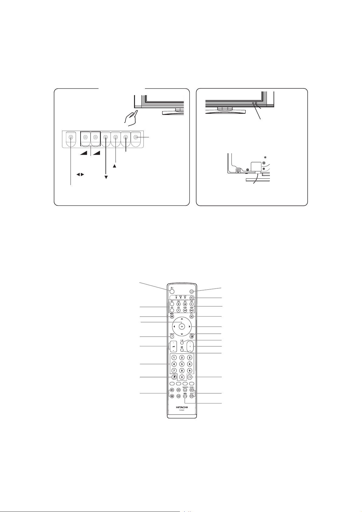
[Main unit]
Control panel
• Adjustment buttons are located
on the bottom.
• The back cover is provided
with indications to distinguish
the adjustment buttons.
+
-
VOLUME
UP/DOWN
buttons
( ADJUST
buttons)
SUB-POWER button
• ( ) indicates the function while the MENU is displayed on the screen.
SELECT button
SELECT button
37PD7800 (PW2)
MENU button
INPUT SELECT button
(OK button)
Remote-control
receiver
Indicating lamp
• The main power switch is located at the back, on the
lower surface.
Main power switch
[Remote control]
POWER button
INPUT SELECT buttons
MENU button
OK button
SOUND MODE button
VOLUME UP/DOWN button
PROGRAM SELECT buttons
(TV)
MULTI MODE button
T/TEXT button
(TV)
RECALL button
FUNCTION SELECT button
DVD CONTROL buttons
FREEZE/RETURN button
SELECT/ADJUST button
PICTURE MODE button
CH I/CH II button (TV)
CHANNEL UP/DOWN button (TV)
MUTE button
MULTI PICTURE button
PHOTO INPUT buttons
SWIVEL button
CLE-960
6

5. New adoption technology
[System control micom I001(M3062)]
Pin function table
No. PIN MANE I/O
1
2
3
4
5
6
7
8 DATA_OUT(FC)
9 DATA_IN(FC)
10 CLK(FC)
11
12
13
14
15
16
17
18
19
20
21
22
23
24
25
26
27
28
29
30
31
32
33
34
35
36
37
38
39
40
41
42
43
44
45
46
47
48
49
50
VREF (+5.0V) I
+5.0V I
NC I/O
OSD_DATA I/O
OSD_CLK I/O
HP_VOL
FE.AGC_O(M) I/O
EDID_PROTECT I/O
TRAP_MAIN I/O
GND I
CNVSS(FLASH) I
DSUB COMP I/O
RGBSW I/O
RESET I
16MHz oscillation O
GND I
16MHz oscillation I
+5.0V I
NMI(+5.0V) I
RMCON(AVC) I/O
V.FREQ_2(VIDEO) I/O
V.FREQ_1/3 I/O
SCV.SYNC I/O
IRQ䋨PM-IRQ) I/O
MCV.SYNC I/O
POWER_LED I/O
H.FREQ_2(VIDEO) I/O
PDP_WVGA_LCD_SW_2 I/O
H.FREQ_1/_3 I/O
PDWN
RXD2 I/O
TXD2 I/O
TXD1(RS232C/FLASH) I/O
RXD1(RS232C/FLASH) I/O
SCLK(FLASH) I/O
BUSY(FLASH) I/O
TXD0(PDP) I/O
RXD0(PDP) I/O
SDA4(panel) I/O
SCL4(panel) I/O
M_ENABLE I/O
M_SCLK I/O
M_SDA I/O
M_WAKEUP I/O
PDPGO(PM_ON) I/O
5V
5V
NC
OSD DATA
OSD CLK
Head Phone Volume
I/O
AGC Voltage(F/E)
FC DATA
I/O
FC DATA
I/O
FC CLOCK
I/O
Memory Protect
TRAP-MAIN
GND
CNVSS(FLASH)
SYNC-SW
SYNC-SW
RESET
OSC-OUT
GND
OSC-IN
5V
5V PULL UP
IR Signal
TA1370(LA7213), COMPONENT2
TA1370(LA7213), COMPONENT(Main)/ DSUB COMPONENT
CVBS for SYNC Detection(Sub Picture)
PANEL MODULE Condition(L:Normal,H:Erroe)
CVBS for SYNC Detection(Main Picture)
L䋺LED ON(Power Save)
TA1370(LA7213), COMPONENT2
PDP/42WVGA/LCD detection
TA1370(LA7213), COMPONENT1(Main), D-SUB
I/O
RESERVE(LVDS Power Down mode(PANEL))
DTT
DTT
DATA(RS-232C)
5V
I
DATA(RS-232C)
GND
I
CLOCK(FRASH MEMORY Writing)
BUSY(FRASH MEMORY Writing)
Ether Net
Ether Net
2
I
C-BUS Contorol DATA
2
I
C-BUS Contorol CLOCK
Media Enable
Media Clock
Media Data
Media Wakeup
PDP PALEL Contorol
37PD7800 (PW2)
FUNCTION
7

37PD7800 (PW2)
No. PIN MANE I/O FUNCTION
CPUGO(PM_CPU) I/O
51
52
53
54
55
56
57
58
59
60
61
62
63
64
65
66
67
68
69
70
71
72
73
74
75
76
77
78
79
80
81
82
83
84
85
86
87
88
89
90
91
92
93
94
95
96
97
98
99
100
EPM (FLASH) I/O
VIDEO.DET_1 I/O
SCL1 I/O
SDA1 I/O
HDMI-RESET I/O
HDMI-HPD_RESET I/O
VIDEO.DET_2 I/O
VIDEO.DET_3 I/O
TUNER.DET_1 I/O
CE (FLASH) I/O
STAND.CIR_DET I/O
SW_L_OUT I/O
SW_R_OUT I/O
M_SW I/O
INITIALIZE I/O
D.RESET(DARST) I/O
DVI-PD I/O
SCDT I/O
HS-DJTR I/O
DVI-SW I/O
CUR_PRTCT I/O
SPRLY I/O
MUTE I/O
ASEL1 I/O AUDIO Signal SW
ASEL2 I/O AUDIO Signal SW
SDA2 I/O
SCL2 I/O
D-SUB COMP_SYNC.SW I/O
BM_SW I/O
RGB_BLK_2 I/O NC
RGB_BLK_3 I/O NC
AUD RST I/O
PDP_WVGA_LCD_SW_1 I/O
+5.0V I
RGB1_DET I/O NC
GND I
WSS_1 I/O NC
WSS_2 I/O NC
WSS_3 I/O NC
TV.AFC(S) I/O AFC Voltage(Sub TUNER)
TV.AFC(M) I/O
FE_AGC_I(M) I/O AGC Voltage(Main TUNER)
FE_AGC_I(S) I/O
HP_DETECT I/O
HDMI_DET I/O
INT_HDMI I/O
NC I/O NC
COMP_SW I/O
DEMP_OUT I/O
PDP PALEL Contorol
FRASH MEMORY Writing
Detecting VIDEO PWB
I2C䋨to PWB TUNER side䋩 FE/MSP3455or MSP3415G/SAA5361/TB1274(Sub)/M306V7/M62320P
I2C䋨to PWB TUNER side䋩 FE/MSP3455or MSP3415G/SAA5361/TB1274(Sub)/M306V7/M62320P
HDMI-Reset
Hot Plug Detect Reset
Detecting VIDEO PWB
Detecting VIDEO PWB
Detecting TUNER PWB
FRASH MEMORY Writing
Detecting SWIVEL PWB
SWIVEL(L-output)
SWIVEL(R-output)
Discriminate terminal of bridge media circuit connecting.
Initializing EEPROM
RESET(DVI)
DVI Contorol
DVI Contorol
DVI Contorol
DVI Contorol
Detecting Powre-SWIVEL
SP ON/OFF Relay Control
MUTE
I2C(NJW1163,AD7414,TA1370)
I2C(NJW1163,AD7414,TA1370)
SYNC-SW
BM switch
RESET for LIPSYNC IC
PDP/42WVGA/LCD detection
GND
AFC Voltage(Main TUNER)
AFC Voltage(Sub TUNER)
HEAD PHONE DETECT
HDMI 5V DET
INT(HDMI)
Component SW Main 㹤 DSUB
deemphasis control output for HDMI
8

37PD7800 (PW2)
No. PIN MANE I/O FUNCTION
101
102
103
104
105
106
107
108
109
110
111
CONTROL I/O
SCL0 I/O
SDA0 I/O
SCL3(EEPROM) I/O
SDA3(EEPROM) I/O
HDMI_CIR_DET I/O
EXT_RESET I/O
OSD_CS I/O
FC_ENABLE I/O
NC I/O
NC I/O
112 IRQ_DTT
113 DTT_POWER
114 DISPEN
115
116
117
HDMI_A_SW I/O
SCL5 I/O
SDA5 I/O
118 FUNC_1
119 FUNC_2
120 NC
121
122
123
124
125
126
127
128
AD_KEY3 I/O
AD_KEY2 I/O
AD_KEY1 I/O
TV.POWER I/O
DIP.DET I/O
POWER_SAVE I/O
GND I
FAN_ALARM *1 I/O
LCD PANEL
2
C-BUS Contorol CLOCK
I
2
I
C-BUS Contorol DATA
I2C-BUS Contorol CLOCK
I2C-BUS Contorol DATA
Detecting HDMI circuit connection
EXTERNAL RESET
OSD CS
FC ENABLE
NC
NC
DTT IRQ
I/O
DTT POWER
I/O
DISPEN
I/O
HDMI AUDIO SW
2
I
C-BUS Contorol CLOCK
2
I
C-BUS Contorol DATA
I/O
Function 1
I/O
Function 2
I/O NC
AD KEY3**
AD KEY2*
AD KEY1(INPUT)
POWRE ON/OFF(H:ON䇮L:STANDBY)
DIP DET
POWRE ON/OFF(L䋺ON(STANDBY䍃POWRE SAVE), H䋺OFF)
GND
FAN ALARM
9

Block diagram
37PD7800 (PW2)
10

37PD7800 (PW2)
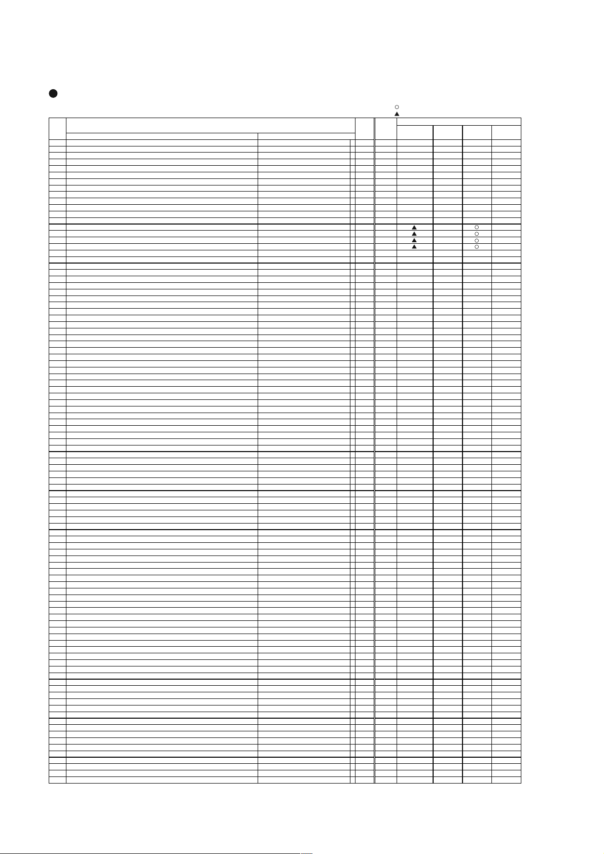
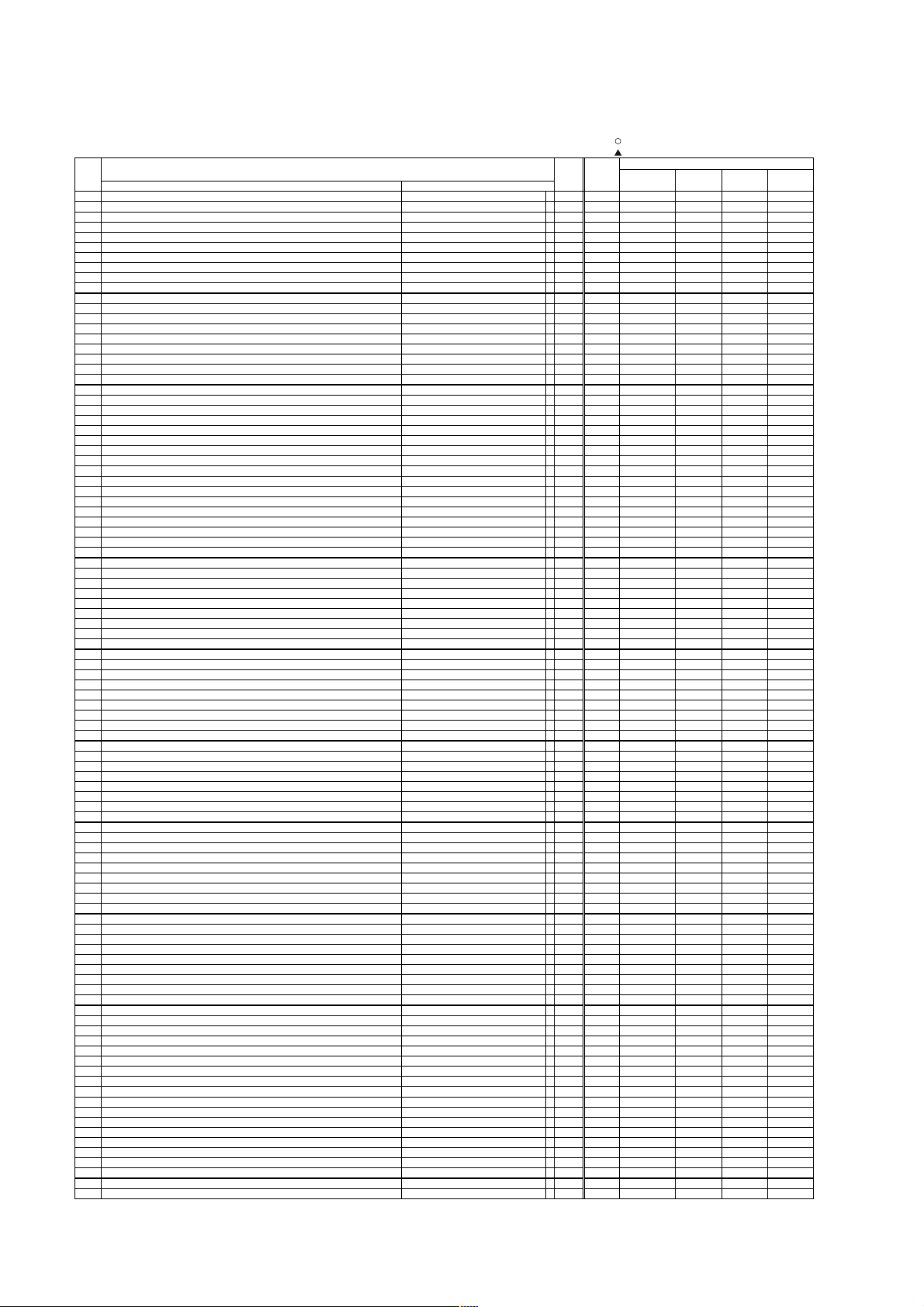
6. Adjustment
● How to get to Adjustment mode
Using the front control buttons with the set turned off (standby) can activate it.
Press the SUB-POWER(
more than 5 seconds.
The set turns on in adjustment mode with OSD.
● Changing data and Selecting Adjustment code
When the set is in adjustment mode, the cursor , , , and OK buttons of the remote control or front panel
may be used as the adjustment keys.
, buttons are used for selecting adjustment code.
, buttons are used for changing data values.
OK button is used for confirming the data.
After finishing the necessary adjustment press MENU button. Adjustment mode is released and the set returns to
normal condition.
● Memory Initialize operation
NOTE: The execution of this function returns the adjustment codes to the preset values, therefore, adjustment
data will be lost.
Procedure
(1) Enter Adjustment Mode.
(2) Select MEMORY INIT adjustment code (No.658) and change the data value from 0 to 1.
(3) Activate MEMORY INIT by pressing OK button for more than 3 seconds.
(4) Select No.525 and change data value from 1 to 0.
(5) Check that the receiving channel goes to P1. Unit is set to preset values.
) button, INPUT SELECT( ) button and button at the same time, and hold for
11
37PD7800 (PW2)
A
_
)
_
)
_
)
_
)
_
)
_
)
_
)
)
)
)
)
A
)
A
)
A
)
A
)
p
)
p
)
p
)
play
play
(
)
(
)
(
)
g
g
g
)
g
)
y
(
(
)
(
)
(
)
(
)
p
p
p
)
p
p
p
p
p
p
p
p
p
p
)
p
p
p
p
p
p
p
p
p
p
p
p
p
[
]
[
]
[
]
)
[
]
[
]
p
[
]
p
[
]
[
]
[
]
)
[
]
[
]
p
[
]
p
(
)[
]
(
)[
]
p
[
]
[
]
p
g
]
g
]
p
(
]
(
]
p
q
]
q
]
p
[
]
[
]
p
[
]
[
]
p
g
]
g
]
p
p
]
p
]
p
p
p
p
p
p
p
p
p
p
p
p
]
p
]
p
]
p
]
p
]
p
p
]
p
p
)
Service
ADJ Function Max. Default
No value FORMATTER VIDEO TUNER PDP
0SUB
1SUB
2SUB
3SUB
4SUB
5SUB
6SUB
7 Sub Color Main 15 8
8 Sub Color Sub 15 8
9 TINT㧔RF
10 TINT 㧔VIDEO
11 TINT 㧔RF
12 TINT 㧔VIDEO
GC adjustment(MFE
13
14
GC adjustment(SFE
15
GC INPUT(MFE
16
GC INPUT(SFE
17 Reference Am
18 Reference Am
19 Reference Am
20 Dis
21 Dis
22 Offset Value
23 Offset Value
24 Offset Value
25 Ter
26 Ter
27 Set Blue Gamma
28 Contrast mode<D
29 Select for WIDE Mode 11
30 PinP Function
31 Black Level
32 Black Level
33 Black Level
34 Black Level
35 YNR In
36 YNR In
37 YNR In
38 YNR In
39 YNR In
40 YNR In
41 YNR In
42 YNR In
43 CNR In
44 CNR In
45 CNR In
46 CNR In
47 CNR In
48 CNR In
49 CNR In
50 CNR In
51 CNR In
52 CNR In
53 main/sub YFRNR level
54 main/sub YFRNR level
55 main/sub YFRNR level
56 main/sub YFRNR level
57 main/sub YFRNR level
58 main/sub YFRNR level
59 main/sub CFRNR level
60 main/sub CFRNR level
61 main/sub CFRNR level
62 main/sub CFRNR level
63 main/sub CFRNR level
64 main/sub CFRNR level
65 B-Y/BޔR-Y/R
66 B-Y/BޔR-Y/R
67 DSB Gain of Vertical for B-Y/B ޔR-Y/R
68 DSB Gain of Vertical for B-Y/B ޔR-Y/R
69 DSB corin
70 DSB corin
71 B-Y/BޔR-Y/R
72 B-Y/BޔR-Y/R
73 Horizontal HPF Peek Fre
74 Horizontal HPF Peek Fre
75 Horizontal Enhancer Gain for B-Y/B,R-Y/R
76 Horizontal Enhancer Gain for B-Y/B,R-Y/R
77 Horizontal DSB Gain for B-Y/B,R-Y/R
78 Horizontal DSB Gain for B-Y/B,R-Y/R
79 Horizontal DSB Corin
80 Horizontal DSB Corin
81 Horizontal Enhancer Cli
82 Horizontal Enhancer Cli
83 B-Y Clam
84 R-Y Clam
85 B-Y Clam
86 R-Y Clam
87 B-Y Clam
88 R-Y Clam
89 B-Y Clam
90 R-Y Clam
91 B-Y Clam
92 R-Y Clam
93 B-Y Clam
94 R-Y Clam
95 P/N ID Main 1 0
96 P/N ID Sub 1 0
97 Shar
98 Free
adjustment items by I
CONTRAST(RF
CONTRAST(AV1
CONTRAST(AV2
CONTRAST(AV3
CONTRAST(AV4
CONTRAST(AV5
CONTRAST(RF
litude(RGB_AMP
litude(RGB_AMP
litude(RGB_AMP
for Max. Amplitude Level Main - for Max. Amplitude Level Sub - -
+/-) of Upper Limit (for FC :RGB-AMP
+/-) of Upper Limit (for TB1274:SUB-CONT
+/-) of Upper Limit (for TB1274:Sub Color
et value of White peak Adj.Sin
et value of Color Level Adj.(for TB1274:Sub Color
ness Gain(RF/NR
ain On/Off 0:Off, 1:On(For 55V
namic> SW (TV) 0:Dynamic, 1:Dynamic+Auto RF 1 1
for PC) 0:PinP, 1:Infomation1, 2:Infomaiton Split 2 0
RGB_AMP
RGB_AMP
RGB_AMP
RGB_AMP
ut Level for AV1-5 Mode RF 7 7
ut Level for AV1-5 Mode VIDEO 7 7
ut Level for AV1-5 Mode Scart-RGB(50/60Hz
ut Level for AV1-5 Mode 480i/576i 7 7
ut Level for AV1-5 Mode 480p/576
ut Level for AV1-5 Mode 1080i-50/60/720
ut Level for DVI-STV Mode 480i/480p/576i/576p/VGA 7 7
ut Level for DVI-STV Mode 1080i-50/60/720
ut Level at Low level for AV1-5 Mode RF/VIDEO 7 3
ut Level at Low level for AV1-5 Mode Scart-RGB(50/60Hz
ut Level at Low level for AV1-5 Mode 480i/576i 7 3
ut Level at Low level for AV1-5 Mode 480p/576
ut Level at Low level for AV1-5 Mode 1080i-50/60/720
ut Level at Low level for DVI-STV Mode 480i/480p/576i/576p/VGA 7 2
ut Level at Low level for DVI-STV Mode 1080i-50/60/720
ut Level at Low level for Dsub Comp. Mode 480i/576i 7 2
ut Level at Low level for Dsub Comp. Mode 480p/576
ut Level at Low level for Dsub Comp. Mode 1080i-50/60/720
VER. Enhancer Gain
VER. Enhancer Gain
of Vertical for B-Y/BޔR-Y/R[CVDSBC0
of Vertical for B-Y/BޔR-Y/R[CVDSBC1
VRE. Enhancer) CLIP 0:CTI[CVECLP0
VRE. Enhancer) CLIP 0:CTI[CVECLP1
for B-Y/B,R-Y/R[CHDSBC0
for B-Y/B,R-Y/R[CHDSBC1
offset NTSC/PAL/480i/576i/480p/576
offset NTSC/PAL/480i/576i/480p/576
offset 1080i-50/60 255 128
offset 1080i-50/60 255 128
offset 720
offset 720
offset[DVI-STB
offset[DVI-STB
offset[DVI-STB
offset[DVI-STB
offset[DVI-STB
offset[DVI-STB
DJ. Items Mode PWB PWB PWB PANEL
MYNRP0
MYNRP5
MYNRP6'
MYNRP6
MYNRP7
MYNRP8
MCNRP0
MCNRP5
MCNRP6'
MCNRP6
MCNRP7
MCNRP8
. SW for B-Y/B,R-Y/R[CHHPF0
. SW for B-Y/B,R-Y/R[CHHPF1
for B-Y/B,R-Y/G 0:CTI[CHECLP0
for B-Y/B,R-Y/G 0:CTI[CHECLP1
CVEG0
CVEG1
CVDSBG0
CVDSBG1
CHEG0
CHEG1
CHDSBG0
CHDSBG1
2
C-bus control (MAIN Part)
Main 15 8
Main/Sub Composite mode 15 8
Main/Sub Composite mode 15 8
Main/Sub Composite mode 15 8
Main/Sub Composite mode 15 8
Main/Sub Composite mode 15 8
Sub 15 8
Main 63 33
Main 63 33
Sub 63 33
Sub 63 33
Main 63 50
Sub 63 50
Main - Sub - RF/VIDEO 254 127
PC 254 127
Multi Picture mode 254
Multi Picture mode 18 2
Single Picture mode 18 2
le Picture mode 237 235
For 55V 1 1
RF/VIDEO 254 127
PC 254 127
HDMI 254 127
For USA NTSC/480i 254 127
NTSC/PAL/ޓMultipicture 7 1
NTSC/PAL-VIDEO 7 0
Scart-RGB(50/60Hz
480i/576i 7 0
480p/576
1080i-50/60/720
NTSC/PAL/㩙㩣㩋 72
NTSC/PAL-VIDEO 7 2
Scart-RGB(50/60Hz
480i/576i 7 2
480p/576
1080i-50/60/720
NTSC/PAL/480i/576i/ޓMultipicture 15 15
480p/576p/1080i-50/60/720
NTSC/PAL/480i/576i/ޓMultipicture 3 0
480p/576p/1080i-50/60/720
NTSC/PAL/480i/576i/ޓMultipicture 7 0
480p/576p/1080i-50/60/720
NTSC/PAL/480i/576i/ޓMultipicture 1 0
480p/576p/1080i-50/60/720
NTSC/PAL/480i/576i/ޓMultipicture 3 2
480p/576p/1080i-50/60/720
NTSC/PAL/480i/576i/ޓMultipicture 15 15
480p/576p/1080i-50/60/720
NTSC/PAL/480i/576i/ޓMultipicture 3 0
480p/576p/1080i-50/60/720
NTSC/PAL/480i/576i/ޓMultipicture 7 0
480p/576p/1080i-50/60/720
NTSC/PAL/480i/576i/ޓMultipicture 1 0
480p/576p/1080i-50/60/720
480i/576i/480p/576p/VGA 255 128
480i/576i/480p/576p/VGA 255 128
1080i-50/60 255 128
1080i-50/60 255 128
720
720
Main/Sub 15 2
18 2
237 235
77
77
77
77
73
73
73
72
72
72
70
70
70
72
72
70
15 9
30
70
10
32
15 9
30
70
10
255
255 128
255 128
255 128
255 128
255 128
: should be adjusted
㪑㩷should be followed previous data
130
128
Changed Component
12

37PD7800 (PW2)
A
p
p
p
p
p
p
p
p
p
p
p
)
p
p
p
p
p
p
p
p
p
p
(
)
(
)
(
)
(
)
(
)
(
)
(
)
(
)
(
)
(
)
(
)
(
)
(
)
(
)
(
)
(
)
(
)
(
)
(
)
(
)
(
)
(
)
(
)
(
)
(
)
(
)
(
)
(
)
(
)
(
)
(
)
(
)
_Q(
)
_f0(
)
_
)
p
(RF)
_DL(
)
_DL(
)
_DL(
)
_DL(
)
_DL(
)
_DL(
)
_DL(
)
_DL(L)
_DL(L')
_DL(
)
_DL(
)
_DL(
)
_DL(
)
_DL(
)
_DL(
)
_DL(
)
_DL(
)
_DL(
)
_DL(
)
_DL(L)
_DL(L')
_DL(
)
_DL(
)
: should be adjusted
ADJ Function Max. Default
No value FORMATTER VIDEO TUNER PDP
99 Free
100 Free
101 Free
102 Free
103 Free
104 Free
105 Free
106 Free
107 Free
108 Free
109 Free
ness Gain(RF) BG/DK/I Sub 15 8
110 Shar
111 Shar
ness Gain(RF) M Sub 15 8
ness Gain(RF) L Sub 15 8
112 Shar
113 Shar
ness Gain(RF) L' Sub 15 8
114 Shar
ness Gain(VIDEO) PAL Sub 15 8
ness Gain(VIDEO) NTSC3.58 Sub 15 8
115 Shar
116 Shar
ness Gain(VIDEO) SECAM,B/W Sub 15 8
ness Gain(VIDEO) NTSC4.43 Sub 15 8
117 Shar
118 Shar
ness Gain(VIDEO) N-PAL Sub 15 8
ness Gain(VIDEO) M-PAL Sub 15 8
119 Shar
120 Shar
ness Gain(S.VIDEO
121 Free
ness f0(RF) BG/DK/I Main/Sub 3 2
122 Shar
123 Shar
ness f0(RF) M Main/Sub 3 2
ness f0(RF) L Main/Sub 3 2
124 Shar
125 Shar
ness f0(RF) L' Main/Sub 3 2
ness f0(VIDEO) PAL Main/Sub 3 2
126 Shar
127 Shar
ness f0(VIDEO) NTSC3.58 Main/Sub 3 2
ness f0(VIDEO) SECAM,B/W Main/Sub 3 2
128 Shar
129 Shar
ness f0(VIDEO) NTSC4.43 Main/Sub 3 2
ness f0(VIDEO) N-PAL Main/Sub 3 2
130 Shar
131 Shar
ness f0(VIDEO) M-PAL Main/Sub 3 2
132 Free
133 Y Out Level M
134 Y Out Level B/G
135 Y Out Level D/K
136 Y Out Level I
137 Y Out Level L
138 Y Out Level L'
139 Y Out Level
140 Y Out Level
141 Free
142 Y Out Level M
143 Y Out Level B/G
144 Y Out Level D/K
145 Y Out Level I
146 Y Out Level L
147 Y Out Level L'
148 Y Out Level
149 Y Out Level
150 Free
151 C Out Level M
152 C Out Level B/G
153 C Out Level D/K
154 C Out Level I
155 C Out Level L
156 C Out Level L'
157 C Out Level
158 C Out Level
159 Free
160 C Out Level M
161 C Out Level B/G
162 C Out Level D/K
163 C Out Level I
164 C Out Level L
165 C Out Level L'
166 C Out Level
167 C Out Level
168 Free
169 BPF
170 BPF
171 C
TRAP_SW(COMB=OFF-PAL/NTSC4.43/NTSC3.58
172 LPF Main/Sub 1 0
173 SECAM D-Tra
174 FILTER SW
175 Y
176 Y
177 Y
178 Y
179 Y
180 Y
181 Y
182 Y
183 Y
184 Y
185 Y
186 Y
187 Y
188 Y
189 Y
190 Y
191 Y
192 Y
193 Y
194 Y
195 Y
196 Y
197 Y
4.5
5.5
6.5
6.0
6.5
6.5
VIDEO
TEXT
4.5
5.5
6.5
6.0
6.5
6.5
VIDEO
TEXT
4.5
5.5
6.5
6.0
6.5
6.5
VIDEO
TEXT
4.5
5.5
6.5
6.0
6.5
6.5
VIDEO
TEXT
4.43MHz
4.43MHz
4.5MHz
5.5MHz PAL/NTSC4.43
5.5MHz SECAM
6.0PAL/NTSC4.43
6.0SECAM
6.5PAL/NTSC4.43
6.5SECAM
VIDEOޓPAL/NTSC4.43
VIDEOޓSECAM
VIDEOޓNTSC
4.5MHz
5.5MHz PAL/NTSC4.43
5.5MHz SECAM
6.0PAL/NTSC4.43
6.0SECAM
6.5PAL/NTSC4.43
6.5SECAM
VIDEOޓPAL/NTSC4.43
VIDEOޓSECAM
DJ. Items Mode PWB PWB PWB PANEL
Sub 15 10
Main 63 15
Main 63 13
Main 63 16
Main 63 14
Main 63 13
Main 63 16
Main 63 15
Main 63 15
Sub 63 19
Sub 63 13
Sub 63 12
Sub 63 13
Sub 63 12
Sub 63 15
Sub 63 13
Sub 63 15
Main 63 7
Main 63 7
Main 63 7
Main 63
Main 63 8
Main 63 8
Main 63 10
Main 63 8
Sub 63 3
Sub 63 8
Sub 63 8
Sub 63 7
Sub 63 7
Sub 63 7
Sub 63 10
Sub 63 13
Main/Sub 3 3
Main/Sub 3 1
Main/Sub 1 0
Main/Sub 1 1
Main/Sub 1 0
Main 10 6
Main 10 4
Main 10 0
Main 10 8
Main 10 9
Main 10 6
Main 10 10
Main 10 5
Main 10 5
Main 10 6
Main 10 8
Main 10 6
Sub 10 5
Sub 10 2
Sub 10 0
Sub 10 7
Sub 10 5
Sub 10 5
Sub 10 5
Sub 10 5
Sub 10 5
Sub 10 5
Sub 10 5
㪑㩷should be followed previous data
5
Changed Component
13

37PD7800 (PW2)
A
_DL(
)
(
)
)
AFC_
)
AFC_
)
AFC_
)
AFC_
)
AFC_
)
AFC_
)
AFC_
)
_
_
_
_
_
_
_
_
_V_
p
p
p
p
p
p
p
p
p
p
p
p
p
p
p
p
_
_
_
p
_
_
p
_
_
_
p
_
_
p
_
_
_
p
_
_
p
_
_
_
p
_
_
p
A
A
A
A
_
_
_
_
p
p
_
_
p
p
p
_
_
p
A
: should be adjusted
ADJ Function Max. Default
No value FORMATTER VIDEO TUNER PDP
198 Y
VIDEOޓNTSC
199 NTSC Comb
200 Cb offset1 Main 15 8
201 Free
202 Cr offset1 Main 15 8
203 Free
204 Cb offset1 Sub 15 8
205 Free
206 Cr offset1 Sub 15 8
207 Free
208 MVM㧔VIDEO
209
210
211
212
213
214
215
216 S
217 S
218 S
219 S
220 BELL
221 S
222 S
223 S
224 S
225 BELL/HPF 㧙 33
226 HS Phase Main 1 0
227 HS Phase Sub 1 0
228 Bandwidth 1 NTSC/PAL/480i/576i 3 2
229 Bandwidth 1 480
230 Bandwidth 1 1080i-50/60/720
231 Bandwidth 2 NTSC/PAL/480i/576i 3 2
232 Bandwidth 2 480
233 Bandwidth 2 1080i-50/60/720
234 Sub Contrast 1 Exce
235 Sub Contrast 1 HDMI 15 0
236 Sub Contrast 2 Exce
237 Sub Contrast 2 HDMI 15 0
238 Sub Color 1 Exce
239 Sub Color 1 HDMI 15 0
240 Sub Color 2 Exce
241 Sub Color 2 HDMI 15 0
242 HV THRU 1 NTSC/PAL/480i/576i/480
243 HV THRU 1 1080i-50/60/720
244 HV THRU 2 NTSC/PAL/480i/576i/480
245 HV THRU 2 1080i-50/60/720
246 H
247 H
248 H
249 H
250 H
251 H
252 H
253 H
254 H
255 H
256 V
257 V
258 V
259 V
260 V
261 V
262 V
263 V
264 V
265 V
266
267
268
269
270 N
271 N
272 N
273 N
274 Free
275 HD POSITION 1 480i/576i 15 0
276 HD POSITION 1 480
277 HD POSITION 1 1080i
278 HD POSITION 1 1080i
279 Free
280 HD POSITION 2 480i/576i 15 0
281 HD POSITION 2 480
282 HD POSITION 2 1080i
283 HD POSITION 2 1080i
284 Y LPF 1 RF 1 1
285 Y LPF 1 VIDEO 1 1
286 Y LPF 2 RF 1 1
287 Y LPF 2 VIDEO 1 1
288 Gain 1 11
289 Gain 2 11
290 YCS MODE NTSC3.58 3 0
291 3D DET 77
292
293 2D-CNR k 30
294 2D-CNR Lim 30
295 GMCON 10
296 Y-NC 10
Comb off
GAIN(AV00
GAIN(AV1
GAIN(AV2
GAIN(AV3
GAIN(AV4
GAIN(AV5
GAIN(Except AV00
B-Y_ADJ Main 15 8
R-Y_ADJ Main 15 8
B-Y_ADJ Sub 15 8
R-Y_ADJ Sub 15 8
f0 Main/Sub 1 0
INHBT 㧙 10
ID 㧙 10
GP 㧙 30
ID 㧙 10
SEP 1 RF/VIDEO 1 0
SEP 1 480i/576i 1 0
SEP 1 480p/576
SEP 1 1080i_50 1 0
SEP 1 1080i_60/720
SEP 2 RF/VIDEO 1 0
SEP 2 480i/576i 1 0
SEP 2 480p/576
SEP 2 1080i_50 1 0
SEP 2 1080i_60/720
SEP 1 RF/VIDEO 1 0
SEP 1 480i/576i 1 0
SEP 1 480p/576
SEP 1 1080i_50 1 0
SEP 1 1080i_60/720
SEP 2 RF/VIDEO 1 0
SEP 2 480i/576i 1 0
SEP 2 480p/576
SEP 2 1080i_50 1 0
SEP 2 1080i_60/720
FC MODE 1 RF 3 0
FC MODE 1 VIDEO 3 0
FC MODE 2 RF 3 0
FC MODE 2 VIDEO 3 0
LVL 1 RF 1 0
LVL 1 VIDEO 1 0
LVL 2 RF 1 0
LVL 2 VIDEO 1 0
FC Gain NTSC3.58 3 0
DJ. Items Mode PWB PWB PWB PANEL
Sub 10 5
Sub 1 1
㧙 10
㧙 30
㧙 30
㧙 30
㧙 30
㧙 30
/576
/576
t HDMI 15 0
t HDMI 15 0
t HDMI 15 0
t HDMI 15 0
/576
/576
/576
50 15 0
60/720
/576
50 15 0
60/720
30
30
32
30
32
30
10
10
10
10
10
10
10
10
10
10
10
10
15 0
15 0
15 0
15 0
㪑㩷should be followed previous data
Changed Component
14
37PD7800 (PW2)
A
p
p
p
p
A
X
y308
y
p
p
p
p
p
y
y
y
p
p
p
A
A
A
A
A
T
A
A
T
A
A
T
A
T
A
T
A
T
T
T
T
T
_
p
p
p
p
A
y
y
p
p
y
y
y
p
p
p
p
p
p
p
A
A
: should be adjusted
ADJ Function Max. Default
No value FORMATTER VIDEO TUNER PDP
297 Y-NC Lim 30
298 2D-YNR k 30
299 2D-YNR Gain 30
300 2D-YNR Lim 30
301 BLK EXP 30
302 CKILL 10
ut Clam
303 Out
304 In
ut Clamp auto 11
305 Int Clam
306 C-ENH
307 YC-MI
308 dumm
309 HSWINV 10
310 dumm
311 V-ENHA Gain NTSC3.58 3 2
312 V-ENHA NL NTSC3.58 3 2
313 H-ENHA Gain NTSC3.58 3 1
314 3DNR Corr for 3DYCS 10
315 Burst ON for 2DYCS???? 10
316 MDMPL ޓ 10
317 MDMBL ޓ 10
318 H-MaskOut ޓ 70
319 V-MaskOut ޓ 70
320 In
321 In
322 Out
323 Out
324 V-ENHA Core NTSC3.58 3 0
325 In
326 Burst Gate Ke
327 S
328 H-WST NTSC3.58 7 3
329 HD Am
330 HD Gain V NTSC3.58 31 13
331 HD Am
332 HD Gain 1 NTSC3.58 31 8
333 HD Am
334 HD Gain 2 NTSC3.58 31 4
335
336
337
338
339
340
341
342
343
344
345
346
347 BCMSLP NTSC3.58 3 3
348 BCSSLP NTSC3.58 3 3
349 BYMSLP NTSC3.58 3 3
350 BYSSLP NTSC3.58 3 2
351 BCMESE
352 BCMFSET NTSC3.58 3 2
353 BCSESE
354 BCSFSET NTSC3.58 3 2
355 BYMESE
356 BYMFSE
357 BYSESE
358 BYSFSET NTSC3.58 3 3
359 BCMUP NTSC3.58 1 1
360 CECMP NTSC3.58 7 4
361 CSCMP NTSC3.58 15 0
362 F1HER NTSC3.58 3 1
363 F1VER NTSC3.58 3 1
364 MREF NTSC3.58 15 2
365 CDEYE NTSC3.58 3 2
366 YDEYE NTSC3.58 3 2
367 MDS NTSC3.58 1 0
368 F-TBC OFF MDMPL NTSC3.58 1 0
369 REC:C
370 V-ENHA Gain Exce
371 V-ENHA NL Exce
372 H-ENHA Gain Exce
373 3D-CNR Lim for 2DYCS 70
374 3D-CNR k for 2DYCS 30
375 3D-CNR Gain for 2DYCS 70
376 3D-YNR Lim for 2DYCS 70
377 3D-YNR k for 2DYCS 30
378 3D-YNR Gain for 2DYCS 70
379 YCS MODE Exce
380
381 dumm
382 dumm
383 V-ENHA Core Exce
384 In
385 Burst Gate Ke
386 S
387 H-WST Exce
388 HD Am
389 HD Gain V Exce
390 HD Am
391 HD Gain 1 Exce
392 HD Am
393 HD Gain 2 Exce
394
395
Manual 10
310 --
ut Y-Delay(Main RF mode) for 3DYCS 74
ut Y-Delay(Main Video mode) for 3DYCS 74
ut-Y-Delay(Main RF Mode) for 3DYCS 15 8
ut-Y-Delay(Main Video Mode) for 3DYCS 15 8
ut Clamp Ke
nc sep LPF NTSC3.58 1 0
1 NTSC3.58 7 6
2 NTSC3.58 7 1
3 NTSC3.58 7 5
CMSLP NTSC3.58 3 1
CSSLP NTSC3.58 3 2
YMSLP NTSC3.58 3 2
YSSLP NTSC3.58 3 2
CMESE
CMFSET NTSC3.58 3 3
CSESE
CSFSET NTSC3.58 3 2
YMESE
YMFSE
YSESE
YSFSET NTSC3.58 3 3
DEC Except NTSC3.58 1 0
FC Gain Except NTSC3.58 3 0
381 -382 --
ut Clamp Ke
nc sep LPF Except NTSC3.58 1 0
1 Except NTSC3.58 7 6
2 Except NTSC3.58 7 1
3 Except NTSC3.58 7 5
CMSLP Except NTSC3.58 3 2
CSSLP Except NTSC3.58 3 2
DJ. Items Mode PWB PWB PWB PANEL
10
10
10
--
NTSC3.58 1 1
NTSC3.58 1 1
NTSC3.58 3 3
NTSC3.58 3 2
NTSC3.58 3 3
NTSC3.58 3 3
NTSC3.58 3 1
NTSC3.58 3 2
NTSC3.58 3 2
NTSC3.58 3 3
NTSC3.58 3 3
NTSC3.58 3 3
t NTSC3.58 3 2
t NTSC3.58 3 1
t NTSC3.58 3 1
t NTSC3.58 3 0
t NTSC3.58 3 0
Except NTSC3.58 1 1
Except NTSC3.58 1 1
t NTSC3.58 7 3
t NTSC3.58 31 13
t NTSC3.58 31 8
t NTSC3.58 31 4
㪑㩷should be followed previous data
Changed Component
15

37PD7800 (PW2)
A
A
A
A
T
A
A
T
A
A
T
A
T
A
T
A
p
p
p
p
T
p
T
p
T
T
T
p
p
p
p
p
p
p
p
p
p
p
_
_
p
_
_
p
_
_
p
_
_
p
(
)
)
(
)
(
)
)
(
)
g(
)
g(
)
g(
)
p
g
]
y
y
g
g
g
y
A
A
y
y
y
p
(
)
(
)
y468
)
A
)
A2_
)
A2_
)
)
_
)
_
)
_
T
_
)
_
)
_
)
A
)
_
)
)
_
_
_
)
_
)
AGC_
y
y
y
y
_H_
_V_
: should be adjusted
ADJ Function Max. Default
No value FORMATTER VIDEO TUNER PDP
396
YMSLP Except NTSC3.58 3 0
397
YSSLP Except NTSC3.58 3 0
CMESE
398
399
CMFSET Except NTSC3.58 3 3
CSESE
400
401
CSFSET Except NTSC3.58 3 2
YMESE
402
403
YMFSE
YSESE
404
405
YSFSET Except NTSC3.58 3 3
406 BCMSLP Exce
407 BCSSLP Exce
408 BYMSLP Exce
409 BYSSLP Exce
410 BCMESE
411 BCMFSET Exce
412 BCSESE
413 BCSFSET Exce
414 BYMESE
415 BYMFSE
416 BYSESE
417 BYSFSET Exce
418 BCMUP Exce
419 CECMP Exce
420 CSCMP Exce
421 F1HER Exce
422 F1VER Exce
423 MREF Exce
424 CDEYE Exce
425 YDEYE Exce
426 MDS Exce
427 F-TBC OFF MDMPL Exce
428 SEPA
LEVEL_DSUB 480i/576i 3 2
LEVEL_DSUB 480p/576
429 SEPA
430 SEPA
LEVEL_DSUB 1080i_50 3 2
LEVEL_DSUB 1080i_60/720
431 SEPA
432 HD-PHASE
433 HD-PHASE
434 HD-PHASE
435 HD-PHASE
436 Heat APC function
437
438
439 Select for APC function 10
440 CCFMD function RF/VIDEO 1 0
441 CCFMD function DVI-PC/DVI-STB/DSUB-RGB 1 0
442 NTSC/EBU
443 NTSC/EBU
444 NTSC/EBU
445 Correction for Trackin
446 Correction for Trackin
447 Correction for Trackin
448 Color Tem
449 Bri
450 D
451 D
452 Histo
453 Histo
454 Histo
455 D
456 FC6 THROUGH 0:OFF, 1:THROUGH ON 10
457
458
459 HD/VD OUTPUT LEVEL 11
460 ISM Control for WVGA For WVGA 1 1
461 SWIVEL DEMO ON
462 WVGA ޓBRIGHTNESS For WVGA 1 0
463 Black insert function 0:Not available, 1:Available For LCD D
464 D
465 DVI-STB Setu
466 HSYNC De-Jitter 0:Low
467 HSYNC De-Jitter 0:Low
468 dumm
469AUTO_FM/AM(D11-D8
470
471
472
473 PRE_AM
474 VOL
475 VOL
476 PRE
477 PRE
478 PRE
479 PRE
480 PRE_FM
481 PRE
482 PRE_FM
483 PRE
484 PRE
485 CM
486 CM
487
488 TEXT H s
489 TEXT V s
490 TEXT
491 TEXT
DSUB 480i/576i 63 20
DSUB 480p/576
DSUB 1080i_50 63 20
DSUB 1080i_60/720
-select(0:1.0, 1:2.2, 2:2.8
-select(0:1.0, 1:2.2, 2:2.8
htness Limitted Function of PANEL [APSON
namic Back Light Correction For LCD 1 1
namic Contrast Correction 11
ram Color Management 11
ram Gradation Amp. 11
ram Enhancer 11
namic Enhancer 11
PL Enhancer 0:OFF, 1:ON For Dynamic mode 1 1
TC INPUT RED SELECT 10
namic Backlight function 0:No, 1:Yes For LCD 1 1
UTO_FM/AM(D 7-D0
THRESHOLD(D11-D8
THRESHOLD(D 7-D0
SCART1(D15-D8
SCART1(D 7-D5
SCAR
FM 4.5MHz(JAPAN
FM 4.5MHz(Except BTSC-SAP mode
FM 4.5MHz(BTSC-SAP
FM 4.5MHz(KOREA㧙Dual/Stereo
FM Except 4.5MHz(Dual/Stereo mode)254 27
NICAM 㧙 254 57
THRESHOLD(D15-D8
THRESHOLD(D7 -D0
LEVEL AGCL 30
HAPC) available 11
CCFORM
CCFORM
CCFORM
. Correction 32
0:None VGA/Others Yes, 1:All none 2:All have DVI-STB 2 0
nc dela
nc dela
POSITION 㧙 254
POSITION 㧙 254
DJ. Items Mode PWB PWB PWB PANEL
Except NTSC3.58 3 3
Except NTSC3.58 3 2
Except NTSC3.58 3 3
Except NTSC3.58 3 3
Except NTSC3.58 3 1
t NTSC3.58 3 3
t NTSC3.58 3 3
t NTSC3.58 3 3
t NTSC3.58 3 2
Except NTSC3.58 3 2
t NTSC3.58 3 2
Except NTSC3.58 3 2
t NTSC3.58 3 2
Except NTSC3.58 3 3
Except NTSC3.58 3 3
Except NTSC3.58 3 3
t NTSC3.58 3 3
t NTSC3.58 1 1
t NTSC3.58 7 4
t NTSC3.58 15 0
t NTSC3.58 3 1
t NTSC3.58 3 1
t NTSC3.58 15 2
t NTSC3.58 3 2
t NTSC3.58 3 2
t NTSC3.58 1 0
t NTSC3.58 1 0
32
32
63 20
63 20
RF/VIDEO 2 1
DVI-PC/DVI-STB/DSUB-RGB 2 1
SD(YCbCr)/Scart-RGB 1 0
DCBON
DCBON
DCBON
Disabled), 1:High(Enabled
Disabled), 1:High(Enabled
HD(YPbPr
DVI-PC/DVI-STB/DSUB-RGB 1 0
RF/VIDEO-Color Temp. Cool 1 1
RF/VIDEO-Color Temp. Nor/War 1 1
DVI-PC/DVI-STB/DSUB-RGB 1 1
namic mode or Da
DVI-PC 1 0
DVI-STB 1 0
㧙 15 2
㧙 254 189
㧙 15 0
㧙 254 112
Except 4.5MHz (Except Dual/Stereo
mode
㧙 254 115
㧙 70
㧙 254 31
4.5MHz(Except KORE
Dual/Stereo mode
Except 4.5MHz(Except Dual/Stereo
mode
㧙 254 0
㧙 254 36
㧙 127
㧙 127 50
㧙
10
11
--
10
50
254 17
254 34
254 32
254 60
254
254 34
254 17
㪑㩷should be followed previous data
0
36
0
42
39
Changed Component
16

37PD7800 (PW2)
A
put[
]
_
y
g
gepump
g
p
yp
p
)
p
)
play
)
play
A
)
(
)
p
p
(s)
y
y528
y
)
(
)
p
y
y
(
)
guage(
)
(
)
A
)
t
(
)
y545
(
)
A
)
(
)
y549
(
)
(
)
j
y
y
pen(
)
g
g
g
p
p
p
p
p
[Dy
[
[
[Dy
[
[
(PC)
y
y
y573
y
y575
y
play
g
g
)
g
)
g
)
y
y
: should be adjusted
ADJ Function Max. Default
No value FORMATTER VIDEO TUNER PDP
492 Select for APC out
493 L
PLL.GAIN 10
494 --
494 dumm
495 HDMI EDID WRITE ENABLE 0:Disenable, 1:Enable 1 0
496 BPMA : Back Porch Mode,Field2 11
497 VCORA : VCO ran
498 CRNTA : chan
499 TESTA : Matchin
500 PRMB :
501 HDCP : HDCP enable criteria 31 12
502 SMPLING For CCD 255 0
503 POLLING For CCD 255 15
504 START For CCD 7 2
505 TIMEOUT For CCD 30 5
506 STATUS For CCD 7 2
507 CCD-HP For CCD 79 40
508 CCD-CLK For CCD 79 57
509 Horizontal Position of OSD 15 7
510 Vertical Position of OSD 15 7
511 Free
ical Value of Contrast OSD DYNAMIC 31 31
512 T
513 Free
erature for Fun start (Temp_High
514 Tem
515 Tem
erature for Fun stop(Temp_Low
516 Dis
of internal temperature (Temperature
of Panel map version 255 -
517 Dis
518
ccumulation time for Panel (hours
519 Reset function of accumulation time for WVGA/LCD Panel 0:Normal 1:Reset 1 0
520 Power Save/Screen Saver On/Off Setting at Initialize, Reset and Shipping
521 PC Power Save function
522 Screen Saver-Picture shift amount 0:1
523 Screen Saver-Picture shift Direction 0:dia /1:cross /2:u
524 Waite Time for POWER SAVE function
525 BURN-IN enable/ disenable 0:Disenable, 1:Enable 1 1
526 BURN-IN mode 22
527 Recover
528 dumm
529 Set Sound S
Power condition at power save mode of PC mode
530
after done RESET function
Select Wide mode for Europe model
531
Normal= 5mode/ For Service= 10 mode
532 Thermo sensor function available or not 0:None, 1:Yes 1 0
533 Video In
534 dumm
534 --
535 Remote Function available 0:NO, 1:YES 11
Function available 0:NO, 1:YES 11
536 Ke
537 DVI-STB/RGB-COMPONENT Function available 0:NO, 1:YES 1 0
538 Terminal Mode Function available 0:Not Available, 1:Available RS232C 1
539 Select color control
540 Lan
541 Hotel Mode
542
nalog Data (0:Keep EEPROM, 1:Not Keep to EEPROM
543 Maximum Volume Limi
544 Power Mode
545 dumm
546 Channel Select
uto_sound 4.5 (0:Korea, 1:BTSC, 2:Japan
547
548 T/TEXT
549 dumm
550 Channel Preset
551 V FREQ 60Hz Force
552 Offset value of ad
553 Use "TINT Offset χ" 0:No, 1:Yes For COMPAL factor
554 PDP-BLK ON/OFF 1:ON, 0:OFF 1 0
555 IIC BUS Data/Clock O
556 Protect for Ima
557 Protect for Ima
558 Protect for Ima
559 Dis
ersion Time of Sustain current 0:2 Times, 1:4 times For Dynamic mode 1 0
ersion Time of Sustain current 0:2 Times, 1:4 times For Natural mode 1 1
560 Dis
561 Dis
ersion Time of Sustain current 0:2 Times, 1:4 times For Cinema mode 1 1
ersion Time of Sustain current 0:2 Times, 1:4 times For PC mode 1 1
562 Dis
563 Dis
ersion Time of Sustain current 0:2 Times, 1:4 times For PC-Movie mode 1 1
564 Q mode 0:Freeze, 1:Move 1, 2:Move 2 For 50Hz
565 Q mode 0:Freeze, 1:Move 1, 2:Move 2 For 50Hz
566 Q mode 0:Freeze, 1:Move 1, 2:Move 2 For 50Hz
567 Q mode 0:Freeze, 1:Move 1, 2:Move 2 For 60Hz
568 Q mode 0:Freeze, 1:Move 1, 2:Move 2 For 60Hz
569 Q mode 0:Freeze, 1:Move 1, 2:Move 2 For 60Hz
570 Q mode 0:Freeze, 1:Move 1, 2:Move 2 For 70Hz
571 dumm
571 -572 --
572 dumm
573 dumm
574 --
574 dumm
575 dumm
level of BM Index 31 4
576 Gra
577 Dis
of BM version 127 578 TA1391: SYNC SW Chan
579 Free
580 Free
581 Countin
582 Countin
583 Countin
584 Lower Limits value for S
585 Lower Limits value for S
e select 30
Test to allow increment of stability counter. 1 1
reamble criteria 31 6
to an error of OSC frequency of Ceramic resonator for timer 62 34
stem at Auto mode of Sound Sys.(0:auto, 1:4.5MHz
ut function available or not at RGB1 & RGB2 mode 0:Not Available, 1:Available 1 1
0:Asia, 1:South America
Refer to below
0:No, 1:Yes
0:Last mode, 1:Pos1, 2-7:V1-6, 8-9:RGB1-2
0:CCIR, 1:CHINA
0:None, 1:Yes
0:VESTEL, 1:GIFU, 2:HAMA, 3:HFDM, 4:AUSTRALIA
0:None, 1:Yes
usted TINT For COMPAL factor
e Retention 0:Off, 1:7%, 2:14%, 3:21%, 4:AUTO Dynamic mode 4 4
e Retention 0:Off, 1:7%, 2:14%, 3:21%, 4:AUTO Natural mode 4 4
e Retention 0:Off, 1:7%, 2:14%, 3:21%, 4:AUTO Cinema mode 4 4
time for discrimination of fH(M30625/TA1370
time for discrimination of fV(M30625/TA1370
time for discrimination of fV(TB1274
DJ. Items Mode PWB PWB PWB PANEL
Except Europe model
current select 70
0:Impossible, 1:Possible
0:Close, 1:Open
e
nc Detect of 2ms interval For AFC at TV mode 254 25
nc Detect of 2ms interval For Free Running at TV mode 254 30
ixel㧛1:2pixel㧛2:3pixel 2 0
/down /3:left/right 3 0
Main RF 2 1
254 58
254 55
125 -
65535 -
P.S/S.S
0:Off/20m
1:On/Off
2:Off/Off
VIDEO/PC 254 15
Main 1 0
0:Keep last condition,
1:Return to normal condition
0:Normal, 1:For service 1 0
Main/Sub 1 0
namic] mode 2 1
Natural] mode 2 1
Cinema] mode 2 1
namic] mode 2 1
Natural] mode 2 1
Cinema] mode 2 1
0:SYNC, 1:HDVD1&2
㧙 31 2
㧙 31 2
㧙 31 2
20
11
--
10
60
20
10
63 63
90
-10
20
11
-41
10
20 11
10
10
20
--
--
10
㪑㩷should be followed previous data
1
Changed Component
17
37PD7800 (PW2)
A
y
y
y
pp
pp
pp
pp
pp
(
(Hz)
(
)
(
(Hz)
(
)
(
)
(
)
g
g
(
)
(
)
(
)
(
)
(
)
(
)
(
)
(
)
(
)
(
)
(
)
(
)
(
)
(
)
(
)
(
)
(
)
(
)
(
)
(
)
y
(
y
g
_
yp
yp
y
y)
j
)
j
A
g
A
)
A
)
A
(
)
j
: should be adjusted
ADJ Function Max. Default
No value F ORMATTER VIDEO TUNER PDP
586
Lower Limits value for S
587
Lower Limits value for S
588
Lower Limits value for S
589
er Limits Value for Sync Detect of 2ms interval For AFC at TV mode
U
590
er Limits Value for Sync Detect of 2ms interval For Free Running at TV mode
U
591
er Limits Value for Sync Detect of 2ms interval For AUTO OFF at TV mode
U
592
er Limits Value for Sync Detect of 2ms interval For Free Running at AV mode
U
593
er Limits Value for Sync Detect of 2ms interval For Power Save at AV mode
U
594
595
596
597
598
599
600
601
602
603
604
605
606
607
608
609
610
611
612
613
614
615
616
617
618
619
620
621
622
623
624
625
626
627
628
629
630
631
632
633
634
635
636
637
638
639
640
641
642
643
644
645
646
647
648
649
650 Check condition of EEPROM of Video PWB board
651
652
653
654
655
656
657
658
659
660 Enter to service menu of FC sub mi-con --
Format PWB 㧕 0:out of range, 128:NO V(or out of spec), 255:interrupt50/60
V detection
H detection
VideoPWB 㧕 0:out of range, 128:NO V(or out of spec), 255:interrupt50/60
V detection
H detection
COLOR SYSTEM CONTROL-MODE
COLOR SYSTEM CONTROL-MODE
Value of 2ms Sync.Detect Main
Countin
Value of 2ms Sync.Detect Sub
Countin
TB1274 Read Data
TB1274 Read Data
TB1274 Read Data
TB1274 Read Data
MSP Read Data
MSP Read Data
MSP Read Data
MSP Read Data
MSP Read Data
MSP Read Data
TA1391FG Read Data
TA1391FG Read Data
TA1391FG Read Data
TA1391FG Read Data
TA1391FG Read Data
TA1391FG Read Data
TA1391FG Read Data
TA1391FG Read Data
TA1370G Read Data
TA1370G Read Data
SiI9993 Read Data SYNC1 : VSYNC/Clock detect/S
SiI9993 Read Data NHRDL1 : N hardware value 1
SiI9993 Read Data NHRDM1 : N hardware value 1
SiI9993 Read Data NHRDH1 : N hardware value 1
SiI9993 Read Data CHRDL1 : CTS hardware value 1
SiI9993 Read Data CHRDM1 : CTS hardware value 1
SiI9993 Read Data CHRDH1 : CTS hardware value 1
SiI9993 Read Data ACR1 : ACR PLL hardware value 1
SiI9993 Read Data ACRS1 : ACR PLL hardware value 1
SiI9993 Read Data SFREQ1 : "Extracted Sampling Frequency 1
channel status b24-27
SiI9993 Read Data CLKFRQ1: Clock Accurac
SiI9993 Read Data ALNG1 : Audio len
SiI9993 Read Data MT
SiI9993 Read Data VTYP1 : AVI infoframe t
SiI9993 Read Data VVER1 : AVI infoframe version code 1
SiI9993 Read Data VINFO11: AVI infoframe data 1
SiI9993 Read Data VINFO21:
SiI9993 Read Data VINFO31:
SiI9993 Read Data VINFO41:
SiI9993 Read Data VINFO51:
SiI9993 Read Data ATYP1 : AUDIO InfoFrame T
SiI9993 Read Data AVER1 : AUDIO InfoFrame Version Code 1
SiI9993 Read Data AINFO11: AUDIO InfoFrame Data B
SiI9993 Read Data AINFO21:
SiI9993 Read Data AINFO31:
SiI9993 Read Data AINFO41:
SiI9993 Read Data AINFO51:
Initialize function for EEPROM of Video PWB board
W/B Initialize
ustment of RGB amplifier(FLAON
Gain ad
ustment of RGB amplifier Sub
Gain ad
utomatic White Peak Adj.Sin
utomatic Color Level Adj.(TB1274BF
utomatic Color Level Adj.(TB1274BF
utomatic White Peak Adj. Multi Picture mode
EEPROM Initialize
Enter to SUB ad
nc Detect of 2ms interval For AUTO OFF at TV mode
nc Detect of 2ms interval For Free Running at AV mode
nc Detect of 2ms interval For Power Save at AV mode
Format PWB㧕 0:out of range, 128:NO H(or out of spec), 255:interrupt 15/28/31/33/45(kHz
Video PWB 㧕 0:out of range, 128:NO H(or out of spec), 255:interrupt 15/28/31/33/45(kHz
00h
01h
00h
01h
CNTROL)(D15-D8
CNTROL)(D 7-D0
STANDARD_RES)(D15-D8
STANDARD_RES)(D 7-D0
STATUS)(D15-D8
STATUS)(D 7-D0
00h
01h
02h
03h
04h
05h
06h
07h
00h
01h
same value at 0x30)"
MD1 : AV mute/HDMI mode 1
0:No, 1:Yes
ust menu
DJ. Items Mode PWB PWB PWB PANEL
0:BW, 2:3.58NTSC, 3:4.43NTSC, 㨯㨯㨯
0:BW, 2:3.58NTSC, 3:4.43NTSC, 㨯㨯㨯
nc detect 1
/Sampling Frequency 1
th/Audio length max 1
e code 1
e Code 1
tes 1
Main
Sub
Main
Main
Sub
Sub
0:Normal, 1:Abnormal(Fail or no
assembl
Main
le Picture mode
Main PAL/NTSC(COMPOSITE
Sub PAL/NTSC(COMPOSITE
254 25
254 30
254 5
254 40
254 45
254 35
254 45
254 200
255 255 255 255 -
--
--
--
--
--
--
--
--
--
--
--
--
--
--
--
--
--
--
--
--
--
--
--
--
--
--
--
--
--
--
--
--
--
--
--
--
--
--
--
--
--
--
--
--
--
--
--
--
--
--
-10
1-
1-
--
--
--
--
--
-10
--
㪑㩷should be followed previous data
Changed Component
18

37PD7800 (PW2)
[
]
[
]
[
]
[
]
[
]
[
]
[
]
[
]
[
]
[
]
[
]
[
]
[
]
[
]
[
]
[
]
[
]
[
]
[
]
[
]
[
]
[
]
[
]
[
]
g
)
g
)
)
g
)
p
g
)
p
g
)
g
)
g
)
g
)
)
g
)
g
t
A
g
t
A
g
t
A
g
t
A
g
t
A
g
t
(CM)
)
(CM)
)
(CM)
)
(CM)
)
(CM)
(CM)
p)
(CM)
p)
(CM)
)
(CM)
(CM)
(CM)
)
(CM)
)
(CM)
)
(CM)
)
(CM)
)
(CM)
(CM)
p)
(CM)
p)
(CM)
)
(CM)
p
)
p
)
p
)
)
p
)
p
)
p
p
)
p
p
)
p
)
)
p
)
)
p
)
p)
p
)
p)
p
)
)
p
)
)
(CM)
(CM)
A
(CM)
A
(CM)
A
(CM)
A
(CM)
A
(CM)
(CM)
p)
(CM)
p)
(CM)
(CM)
)
(CM)
e
g
e
[
]
(
)[
]
[
]
p
Service
adjustment items by I
(*The change to a sub menu. press “ok” key after no.659 with a main menu)
ADJ Function Max. Default
No. Value FORMATTER VIDEO TUNER PDP
0 R DRIVE1
1 G DRIVE1
2 B DRIVE1
3 R DRIVE2
4 G DRIVE2
5 B DRIVE2
6 R DRIVE3
7 G DRIVE3
8 B DRIVE3
9 R DRIVE4
10 G DRIVE4
11 B DRIVE4
12 R DRIVE1
13 G DRIVE1
14 B DRIVE1
15 R DRIVE2
16 G DRIVE2
17 B DRIVE2
18 R DRIVE3
19 G DRIVE3
20 B DRIVE3
21 R DRIVE4
22 G DRIVE4
23 B DRIVE4
24 Bri
25 Bri
26 Bri
27 Bri
28 Bri
29 Bri
30 Bri
31 Bri
32 Bri
33 Bri
34 Bri
35 Bri
36 Bri
37 Bri
38 Bri
39 Color Center
40 Color Center
41 Color Center
42 Color Center
43 Color Center
44 Color Center
45 Color Center
46 Color Center
47 Color Center
48 Tint Center
49 Tint Center
50 Tint Center
51 Tint Center
52 Tint Center
53 Tint Center
54 Tint Center
55 Tint Center
56 Tint Center
57 Tint Center
58 Tint Center
59 Center of Shar
60 Center of Shar
61 Center of Shar
62 Center of Shar
63 Center of Shar
64 Center of Shar
65 Center of Shar
66 Center of Shar
67 Center of Shar
68 Center of Shar
69 Center of Shar
70 Center of Shar
71 Center of Shar
72 Contrast Center
73 Contrast Center
74 Contrast Center
75 Contrast Center
76 Contrast Center
77 Contrast Center
78 Contrast Center
79 Contrast Center
80 Contrast Center
81 Contrast Center
82 Contrast Center
83 Contrast Center
84 Maximum Value of Contrast at REAL/NORMAL mod
85 Offset Value of Contrast data at SPLIT mode 120 53
86 Offset value of
87 Horizontal Enhanc
88 Vertical Enhance TEXT 3 3
89 Horizontal filter SW
90
91
RF/VIDEO/DSUB-COMP
RF/VIDEO/DSUB-COMP
RF/VIDEO/DSUB-COMP
RF/VIDEO/DSUB-COMP
RF/VIDEO/DSUB-COMP
RF/VIDEO/DSUB-COMP
RF/VIDEO/DSUB-COMP
RF/VIDEO/DSUB-COMP
RF/VIDEO/DSUB-COMP
RF/VIDEO/DSUB-COMP
RF/VIDEO/DSUB-COMP
RF/VIDEO/DSUB-COMP
DVI-PC/DVI-STB/DSUB-RGB
DVI-PC/DVI-STB/DSUB-RGB
DVI-PC/DVI-STB/DSUB-RGB
DVI-PC/DVI-STB/DSUB-RGB
DVI-PC/DVI-STB/DSUB-RGB
DVI-PC/DVI-STB/DSUB-RGB
DVI-PC/DVI-STB/DSUB-RGB
DVI-PC/DVI-STB/DSUB-RGB
DVI-PC/DVI-STB/DSUB-RGB
DVI-PC/DVI-STB/DSUB-RGB
DVI-PC/DVI-STB/DSUB-RGB
DVI-PC/DVI-STB/DSUB-RGB
htness Center (CM
htness Center (CM
htness Center (CM
htness Center (CM
htness Center (CM
htness Center (CM
htness Center (CM
htness Center (CM
htness Center (CM
htness center (CM) offse
htness center (CM) offse
htness center (CM) offse
htness center (CM) offse
htness center (CM) offse
htness center (CM) offse
Enhancer Gain
ADJ. Items Mode PWB PWB PWB PANEL
ness(Y-Enhancer Gain for HV
ness(Y-Enhancer Gain for HV
ness(Y-Enhancer Gain for HV
ness(Y-Enhancer Gain for HV
ness(Y-Enhancer Gain for HV
ness(Y-Enhancer Gain for HV
ness(Y-Enhancer Gain for HV
ness(Y-Enhancer Gain for HV
ness(Y-Enhancer Gain for HV
ness(Y-Enhancer Gain for HV
ness(Y-Enhancer Gain for HV
ness(Y-Enhancer Gain for HV
ness(Y-Enhancer Gain for HV
ain for Black Stretch function Except OFF/LOW/HIGH mode 63
HHPF0
HHPF1
HHPF2
2
C-bus control (SUB adjust menu)
٤㧦should be adjusted
ً㧦should be followed previous data
Changed Component
COOL 255 255 ً٤
COOL 255 255 ً٤
COOL 255 255 ً٤
NORMAL 255 255 ً٤
NORMAL 255 255 ً٤
NORMAL 255 255 ً٤
WARM 255 255 ً٤
WARM 255 255 ً٤
WARM 255 255 ً٤
BLACK & WHITE 255 255 ً٤
BLACK & WHITE 255 255 ً٤
BLACK & WHITE 255 255 ً٤
COOL 255 255 ً٤
COOL 255 255 ً٤
COOL 255 255 ً٤
NORMAL 255 255 ً٤
NORMAL 255 255 ً٤
NORMAL 255 255 ً٤
WARM 255 255 ً٤
WARM 255 255 ً٤
WARM 255 255 ً٤
BLACK & WHITE 255 255 ً٤
BLACK & WHITE 255 255 ً٤
BLACK & WHITE 255 255 ً٤
NTSC/PAL/ޓMultipicture 254 128
Scart-RGB(50/60Hz
480i/576i/480p/576
1080i-50/60/720
DVI-PC 254 128
DVI-STB 254 128
DSUB-RGB 254 128
Expand DSUB-RGB (Reserved
HDMI 254 128
V1 254 127
V2 254 127
V3 254 127
V4 254 127
V5 254 127
DSUB-COMP 254
SD(YCbCr)(50Hz
SD(YCbCr)(60Hz
Scart-RGB(50/60Hz
HD(YPbPr)(50/60Hz
DVI-PC 127 64
DVI-STB(480i/576i/480p/576
DVI-STB(1080i-50/60/720
DVI-STB(VGA
DSUB-RGB 127 64
PAL 254
Scart-RGB(50Hz
Scart-RGB(60Hz
SD(YCbCr)(50Hz
SD(YCbCr)(60Hz
HD(YPbPr)(50/60Hz
DVI-PC 254 128
DVI-STB(480i/576i/480p/576
DVI-STB(1080i-50/60/720
DVI-STB(VGA
DSUB-RGB 254 128
RF 31 10
VIDEO 31 15
Scart-RGB(50/60Hz
480i/576i 31 10
480p/576
720
1080i-50/60 31 10
TEXT(for split
DVI-STB(480i/576i
DVI-STB(480p/576
DVI-STB(720
DVI-STB(1080i-50/60
DVI-STB(VGA
RF 254 137
V1 254 137
V2 254 137
V3 254 137
V4 254 137
V5 254 137
DVI-PC 254 128
DVI-STB(With Setu
DVI-STB(Without Setu
DSUB-RGB 254 128
Expand DSUB-RGB (Reserved
DSUB-COMP 254 137
TEXT 3 3
NTSC/480i 1 0
PAL/576i 1 0
480p/576p/1080i-50/60/720
254 128
254 128
254 124
254 128
126
127 72
127 68
127 50
127 70
127 62
127 62
127 62
125
254 140
254 120
254
123
254
130
254 135
254 128
254 128
254 128
31 14
31 15
31 6
31 19
31 14
31 10
31 6
31 10
31 10
254 149
254 128
254 128
254 188
32
10
19
37PD7800 (PW2)
]
(
)[
]
[
]
[
]
[
]
)
[
]
[
]
p
[
]
p
[
]
g
]
(
)[
]
[
]
[
]
[
]
)
[
]
[
]
p
[
]
p
[
]
g
C
g
]
[
]
[
]
)
[
]
p
[
]
p
[
]
t
g
]
[
]
p
p
]
(
)[
]
p
]
[
]
p
)[
]
[
]
p
]
(
)[
]
[
]
[
]
p
)[
]
[
]
[
]
[
]
p
[
]
p
[
]
[
]
[
]
p
[
]
p
g
]
[
]
p
p
]
[
]
p
p
]
[
]
p
g
]
[
]
p
[
]
[
]
p
[
]
p
[
]
[
]
[
]
p
[
]
p
g
]
[
]
p
p
]
[
]
p
p
]
[
]
[
]
)
[
]
p
g
]
[
]
p
q
]
[
]
p
[
]
p
A
A
(
])
(
])
(
])
g
])
g
])
g
])
(
])
(
])
(
])
p
])
p
])
p
])
٤㧦should be adjusted
ً㧦should be followed previous data
ADJ Function Max. Default
No. Value FORMATTER VIDEO TUNER PDP
92 Horizontal Coring Level [HECOR1
Enhancer Gain
93
94
95
96
97
98
99
100
101 Vertical Corin
102
Enhancer Gain
103
104
105
106
107
108
109
110 Enhancer
111 Corin
112
113
114
115
116
117 Corin
118
119 YFRNR in
120 HD-NTSC, HD-PAL
121 4
122
123 YFRNR in
124
125 CFRNR in
126 HD-NTSC, HD-PAL
127
128
129 CFRNR in
130
131 Vertical Enhancer Gain for Y/G
132
133
134
135 Vertical DSB Gain for Y/G
136
137
138 Vertical DSB Corin
139
140 Vertical Enhancer Cli
141
142 Vertical Cli
143
144 Vertical Non Linear Peakin
145
146 Horizontal Enhancer Gain for Y/R
147
148
149
150 Horizontal DSB Gain for Y/R
151
152
153 Horizontal DSB Corin
154
155 Horizontal Enhancer Cli
156
157 Horizontal Cli
158
159
160
161 Horizontal Non Linear Peakin
162
163 Horizontal HPF Peak Fre
164
165
166 Initial value of Contrast Extend 1 of Panel Life function 127 93
167 Interval time of correction time Extend 1 of Panel Life function 127 10
dditional value of Contrast Extend 1 of Panel Life function 127 1
168
169 Initial value of Contrast Extend 2 of Panel Life function 127 63
170 Interval time of correction time Extend 2 of Panel Life function 127 6
171
dditional value of Contrast Extend 2 of Panel Life function 127 1
172 Menu Init. Contrast
173 Menu Init. Contrast
174 Menu Init. Contrast
175 Menu Init. Bri
176 Menu Init. Bri
177 Menu Init. Bri
178 Menu Init. Color
179 Menu Init. Color
180 Menu Init. Color
181 Menu Init. Shar
182 Menu Init. Shar
183 Menu Init. Shar
Level[VECOR1
ain of VH for
Amplitude for Y/G[YC0R0
Amplitube for B-Y/B,R-Y/R[CC0R0
ut Gain(Main) 2pictures[MYNRG0
ut Gain(Sub
ut Gain(Main) 2pictures[MCNRG0
ut Gain(Sub
Offset Level[YVECLPL0
Offset Level for Y/R[YHECLPL0
htness(-31[0]㨪+31[62
htness(-31[0]㨪+31[62
htness(-31[0]㨪+31[62
ADJ. Items Mode PWB PWB PWB PANEL
HECOR2
HECOR3
HECOR4
HECOR5'
HECOR5
HECOR6
HECOR7
HECORPC
VECOR2
VECOR3
VECOR4
VECOR5'
VECOR5
VECOR6
VECOR7
VECORPC
YC0R1
YC0R2
YC0R3
YC0R4
YC0R5
CC0R1
sub
ictures[MYNRG2
MYNRG3
YCNRG1
SUB
MCNRG2
MCNRG3
SCNRG1
YVEG1
YVEG2
YVEG3
YVDSBG1
YVDSBG2
for Y/G[YVDSBC0
YVDSBC1
for Y/G 0:LTI[YVECLP0
YVECLP1
YVECLPL1
YVNLP1
YHEG1
YHEG2
YHEG3
YHDSBG1
YHDSBG2
for Y/R[YHDSBC0
YHDSBC1
YHDSBC1
YHECLPL1
YHECLPL3
YHECLPL2
YHNLP1
YHHPF1
YHHPF2
-31[0]㨪+40[71
-31[0]㨪+40[71
-31[0]㨪+40[71
-31[0]㨪+31[62
-31[0]㨪+31[62
-31[0]㨪+31[62
ness(-15[0]㨪+15[30
ness(-15[0]㨪+15[30
ness(-15[0]㨪+15[30
MYNRG1
YCNRG0
MCNRG1
SCNRG0
YVEG0
YVDSBG0
for Y/G[YVNLP0
YHEG0
YHDSBG0
for Y/R 0:LTI[YHDSBC0
for Y/G[YHNLP0
. SW for Y/R[YHHPF0
NTSC-RF 15 3
PAL-RF/ޓMultipicture 15 2
NTSC-VIDEO 15 1
PAL-VIDEO 15 1
Scart-RGB(50/60Hz
480i/576i 15 2
480p/576
1080i-50/60/720
PC 15 1
NTSC-RF 15 1
PAL-RF/ޓMultipicture 15 8
NTSC-VIDEO 15 1
PAL-VIDEO 15 1
Scart-RGB(50/60Hz
480i/576i 15 0
480p/576
1080i-50/60/720
PC 15 0
TEXT 31 0
NTSC/PAL-RF/ޓMultipicture 7 7
NTSC/PAL-VIDEO 7 5
480i/576i/Scart-RGB(50/60Hz
480p/576
1080i-50/60/720
NTSC/PAL 㧿-inpu
NTSC/PAL/480i/576i/ޓMultipicture 7 1
480p/576p/1080i-50/60/720
HD-except HD 7 1
HD-HD 7 4
NT-* /PAL-* 7 1
HD-* 7 4
2pictures 7 4
4pictures/12pictures 7 1
HD-except HD 7 3
HD-HD 7 4
NT-* /PAL-* 7 4
HD-* 7 4
2pictures 7 3
4pictures/12pictures 7 4
NTSC/PAL(-except RF)/480i/576i 15 15
480p/576
1080i-50/60/720
PAL(-RF)/ޓMultipicture 15 15
NTSC/PAL/480i/576i/ޓMultipicture 3 3
480p/576
1080i-50/60/720
NTSC/PAL/480i/576i/ޓMultipicture 7 7
480p/576p/1080i-50/60/720
NTSC/PAL/480i/576i/ޓMultipicture 1 1
480p/576p/1080i-50/60/720
NTSC/PAL/480i/576i/ޓMultipicture 15 15
480p/576p/1080i-50/60/720
NTSC/PAL/480i/576i/ޓMultipicture 63 0
480p/576p/1080i-50/60/720
NTSC/PAL(-except RF)/480i/576i 15 15
480p/576
1080i-50/60/720
PAL(-RF)/ޓMultipicture 15 15
NTSC/PAL/480i/576i/ޓMultipicture 3 2
480p/576
1080i-50/60/720
NTSC/PAL/480i/576i/ޓMultipicture 7 7
480p/576p/1080i-50/60/720
NTSC/PAL/480i/576i/ޓMultipicture 1 0
480p/576p/1080i-50/60/720
RF/ޓMultipicture 15 4
NTSC/PAL-VIDEO 15 4
480i/576i/Scart-RGB(50/60Hz
480p/576p/1080i-50/60/720
NTSC/PAL/480i/576i/ޓMultipicture 63 0
480p/576p/1080i-50/60/720
NTSC/PAL/480i/576i/ޓMultipicture 3 2
480p/576
1080i-50/60/720
For Dynamic 71 62
For Natural 71 62
For Cinema 71 51
For Dynamic 62 31
For Natural 62 31
For Cinema 62 33
For Dynamic 62 36
For Natural 62 31
For Cinema 62 21
For Dynamic 30 20
For Natural 30 15
For Cinema 30 10
15 0
15 1
15 1
15 1
15 15
15 15
74
71
71
74
71
15 4
15 15
30
32
70
10
15 8
63 0
15 15
15 15
30
32
77
10
15 10
15 0
63 0
32
32
Changed Component
20

37PD7800 (PW2)
p.(
p.(
(
])
(
])
(
])
(
])
(
])
(
])
(
])
(
])
(
])
p
)
)
p
)
p)
p
)
p)
p
)
)
p
)
)
(CM)
p)
(CM)
p)
(CM)
p)
(CM)
p)
(CM)
p)
(CM)
p)
p
p
p
)L
p
'
p
L
p
p
p
p
L
p
L
p
)
٤㧦should be adjusted
ً㧦should be followed previous data
ADJ Function Max. Default
No. Value FORMATTER VIDEO TUNER PDP
184 Menu Init. Color Temp.(Cool[0]/Normal[1]/Warm[2]/B&W[3])For Dynamic 3 0
185 Menu Init. Color Tem
186 Menu Init. Color Tem
187 Menu Init. Black stretch
188 Menu Init. Black stretch
189 Menu Init. Black stretch
190 Menu Init. YNR
191 Menu Init. YNR
192 Menu Init. YNR
193 Menu Init. LTI
194 Menu Init. LTI
195 Menu Init. LTI
196 Center of Shar
197 Center of Shar
198 Center of Shar
199 Center of Shar
200 Center of Shar
201 Color Center
202 Color Center
203 Color Center
204 Tint Center
205 Tint Center
206 Tint Center
207 Shar
208 Shar
209 Shar
210 Shar
211 Shar
212 Shar
213 Shar
214 Shar
215 Shar
216 Shar
217 Shar
Off[0]/Low[1]/Mid.[2]/High[3
Off[0]/Low[1]/Mid.[2]/High[3
Off[0]/Low[1]/Mid.[2]/High[3
ness Gain(RF) BG/DK/I Main 15
ness Gain(RF) M Main 15 8
ness Gain(RF
ness Gain(RF) L
ness Gain(VIDEO) PA
ness Gain(VIDEO) NTSC3.58 Main 15 10
ness Gain(VIDEO) SECAM,B/W Main 15 8
ness Gain(VIDEO) NTSC4.43 Main 15 8
ness Gain(VIDEO) N-PA
ness Gain(VIDEO) M-PA
ness Gain(S.VIDEO
ADJ. Items Mode PWB PWB PWB PANEL
Cool[0]/Normal[1]/Warm[2]/B&W[3])For Natural 3 1
Cool[0]/Normal[1]/Warm[2]/B&W[3])For Cinema 3 2
Off[0]/Low[1]/Mid.[2]/High[3
Off[0]/Low[1]/Mid.[2]/High[3
Off[0]/Low[1]/Mid.[2]/High[3
Off[0]/Low[1]/High[2
Off[0]/Low[1]/High[2
Off[0]/Low[1]/High[2
ness(HV Enhancer Gain for Y
ness(HV Enhancer Gain for Y
ness(HV Enhancer Gain for Y
ness(HV Enhancer Gain for Y
ness(HV Enhancer Gain for Y
For Dynamic 3 1
For Natural 3 1
For Cinema 3 0
For Dynamic 2 0
For Natural 2 0
For Cinema 2 0
For Dynamic 3 2
For Natural 3 1
For Cinema 3 0
HDMI(480i/576i
HDMI(480p/576
HDMI(720
HDMI(1080i-50/60
HDMI(VGA
HDMI-YCbCr(50Hz:576i/576
HDMI-YCbCr(60Hz:480i/480
HDMI-YPbPr(1080i-50/60/720
HDMI-YCbCr(50Hz:576i/576
HDMI-YCbCr(60Hz:480i/480
HDMI-YPbPr(1080i-50/60/720
Main 15 8
Main 15 8
Main 15 8
Main 15 8
Main 15 8
Main 15 8
31 10
31 20
31 15
31 7
31 10
127 65
127 65
127 65
254 126
254 126
254 126
5(42),8(32)
Changed Component
21
37PD7800 (PW2)
The Expression of input signal mode (format)
PAL1: RF, S and Composite of PAL/SECAM
PAL2: Component of PAL (YCBCR)
PAL3: Component of PAL (YPBPR)
PAL4: Component of PAL (YCBCR-SCART)
PAL: PAL1-4
NT1: S and Composite of NTSC
NT2: Component of NTSC (YCBCR)
NT3: Component of NTSC (YPBPR)
NT4: Component of NTSC (YCBCR-SCART)
NTSC: NTSC1-4
HD1-6: Component (shown in the table )
HD7: Component of 1080i/50 (YPBPR)
HD8: Component of 1080i/50 (YCBCR)
HD9: Component of 576p (YPBPR)
HD10: Component of 576p (YCBCR)
HD: HD1-10 of Component
TV: NTSC / HD
PC: PC signal
Video
Input
AV1
AV2
Judgment of
H.Frequency
15.75kHz
(576i)
15.75kHz
(480i)
31.25kHz
(576p)
31.50kHz
(480p)
45.00kHz
(720p)
28.125kHz
(1080i)
33.75kHz
(1080i)
Video Input
Setup
Auto PAL2
SDTV/DVD PAL2
HDTV PAL3
Auto NT2
SDTV/DVD NT2
HDTV NT3
Auto HD10
SDTV/DVD HD10
HDTV HD9
Auto HD3
SDTV/DVD HD3
HDTV HD2
Auto HD5
SDTV/DVD HD6
HDTV HD5
Auto HD7
SDTV/DVD HD8
HDTV HD7
Auto HD1
SDTV/DVD HD4
HDTV HD1
Mode
Factory Reset
After all of the adjustments of main chassis are finished, perform FACTORY RESET.
Press the SUB-POWER( ) button, INPUT SELECT( ) button and button at the same time, and hold for
more than 5 seconds.
The unit is set to factory settings.
22

Item Power Unit Vs, Va Adjustment
Applicable Model All models
Preparation Procedure
(1) Turn on the set and perform
pre-heat run more than 1 min
on burn-in screen.
(2)
Receive full back pattern signal
(or Video silence signal;
but it will be automatically turned off
after a few seconds by power save function.)
(3) Connect voltmeter leads to Vs
(or Va) and GND test points of the power unit.
37PD7800 (PW2)
(1) Turn Vs ADJ to adjust Vs voltage
to be within ±0.1V of the value
specified in the label on the panel.
Adjust within ± 1V at Vs1
Adjust within ± 0.1V at Vs2
(2)
Turn Va ADJ to adjust Va voltage
to be within ±0.2V of the value specified
in the label on the panel.
Adjust within ± 1V at Va1
Adjust within ± 0.2V at Va2
Reconfirm that Vs voltage remains within
(3)
±0.1V of the specified value.
Readjust if it’s outside of the margin.
Label example
<LOT>N6
Vs= 80.0V Va=60.0V
Vw=140.0V Vx=60.0V
Y-sus
Power
Supply
Unit
Label
X-sus
Panel Module
C
V
(Rear View)
sV
aV
DNG
niP
tseT aV / sV 99N
RV tnemtsujda esraoc sV:1sV
RV tnemtsujda enif sV:2sV
RV tnemtsujda enif aV:2aV
RV tnem
tsujda esraoc aV:1a
S
MADE IN THAILAND
5147FPM ataruM
******** N/
23

37PD7800 (PW2)
Item AGC Adjustment (Main)
Applicable Model All models
Preparation Procedure
(1) Turn on the set and perform pre-heat run
more than 20 min.
(2) Receive AGC adjustment signal.
CCIR ch-5: (175.25MHz)
PAL B/G PHILIPS
Field : -50dBm
(3)
(1)
Receive AGC adjustment signal.
Indicate Service Adjustment menu (Main).
Display the following signals at the same time.
(2)
Service Adjustment No.13 (AGC Adjustment)
No.15 (AGC Input)
Raise No.13 data value until No.15 data is
saturated(This point: AGC-MAX)
(4)
With monitoring No.15
reduce No.13 data value and press [OK] key
at the point when No.15 data
comes down.
AGC Voltage
AGC Max.
AGC
Adj. point
AGC POINT
24

Item AGC Adjustment (Sub)
Applicable Model All models
Preparation Procedure
(1)
Turn on the set and perform pre-heat run
more than 20 min.
Receive AGC adjustment signal.
(2)
CCIR ch-5: (175.25MHz)
PAL B/G PHILIPS
Field : -50dBm
37PD7800 (PW2)
(1)
Receive AGC adjustment signal.
Indicate Service Adjustment menu (Sub).
Display the following signals at the same time.
(2)
Service Adjustment No.14 (AGC Adjustment)
No.16 (AGC Input)
(3)
(4)
Raise No.14 data value until No.16 data is
saturated(This point: AGC-MAX)
With monitoring No.16
reduce No.14 data value and press [OK] key
at the point when No.16 data comes down.
AGC Voltage
AGC Max.
AGC
Adj. point
AGC POINT
25
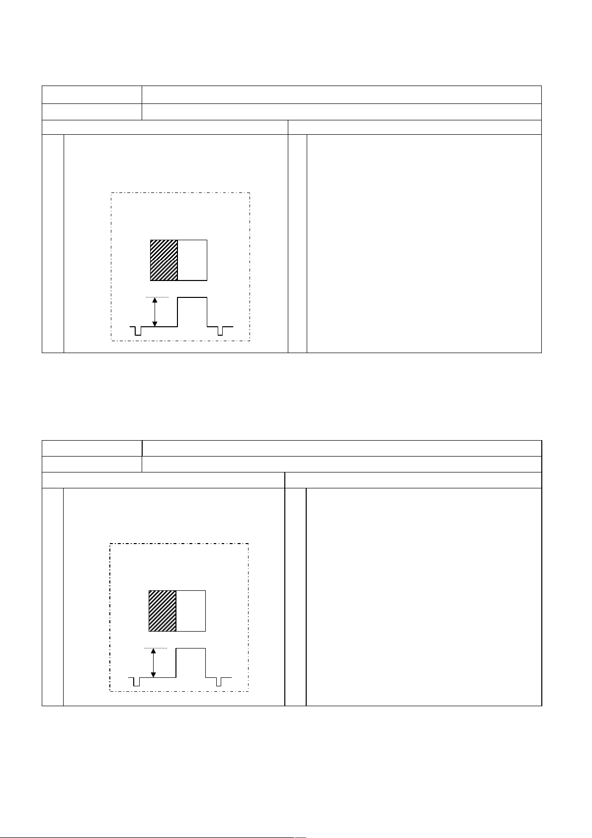
37PD7800 (PW2)
Item
RGB Amplitude Adjustment (PC D-Sub input)
Applicable Model All models
Preparation Procedure
(1)
Input RGB amplitude adjustment signal of VGA
(60Hz) into RGB2 [D-sub] terminal.
Black pattern: Set pedestal level.
Characters must not be inserted
into this signal.
White
Black
0.7V
[Note] Never adjust without use of the specified signal.
If that were done by mistake, the picture would become abnormal in black level, contrast and color.
In this case, it will be recovered by re-adjustment in the specified way.
(1)
Receive PC signal (VGA [60Hz]), and indicate
Service Adjustment Menu.(Main)
(2)
Select No.652 of Service Adjustment Menu.
Press [OK] key more than 2 seconds to start the
automatic adjustment.
The adjustment completes when the OSD
reappears.
Item
RGB Amplitude Adjustment (Main/Sub)
Applicable Model All models
Preparation Procedure
(1) Input 576p or 480p adjustment signal
into AV1 terminal.
Black pattern: Set pedestal level.
Characters must not be inserted
into this signal.
White
Black
0.7V
[Note] Never adjust without use of the specified signal.
If that were done by mistake, the picture would become abnormal in black level, contrast and color.
In this case, it will be recovered by re-adjustment in the specified way.
(1) Receive 576p or 480p adjustment signal on AV1
terminal input.
Indicate Service Adjustment Menu.
(2)
Select No.652 (RGB amplitude gain adjustment
Main) of Service Adjustment Menu.
Press [OK] key more than 2 seconds to start the
automatic adjustment.
The adjustment completes when the indication
[Auto Mode] at the bottom of the screen
disappears.
Select No.653 (RGB amplitude gain adjustment
(3)
Sub) of Service Adjustment Menu.
Press [OK] key more than 2 seconds to start the
automatic adjustment.
The adjustment completes when the indication
[Auto Mode] at the bottom of the screen
disappears.
26

37PD7800 (PW2)
Item
Applicable Model All models
Adjustment Preparations
(1)
Set the signal generator output as All White.
(2)
Component signal (480i)
Video level : 0.700Vp-p
Sync level : 0.300Vp-p
Setup level : 0V
Picture Menu is set as [RESET].
Confirm that the mode is set as Factory
(4) (4)
Adjustment mode.
Video Color Temperature Adjustment (Cool)
(1)
(2)
(3)(3)
Adjustment Procedures
Perform the following adjustment with the remote
control
Set the CRT color analyzer (CA100) at the center
of the panel.
Ensure that the service adjustment
menu (sub menu) No. 0, 1, 2, are all set as 255.
After receiving the video signal, step down the two
(or one) among adjustment No. 0, 1, 2 and adjust
the values as shown below.
Note)
At least one of the data shoud be 255.
Specification
Video color temperature (Cool)
x=0.258±0.005
y=0.273±0.005
27

37PD7800 (PW2)
Item
Applicable Model All models
(1) Set signal generator output as
All White (Window ratio: 100%).
(2) Component signal (480i)
Video level : 0.700Vp-p
Sync level : 0.300Vp-p
Setup level : 0V
(3)
Check that Picture Menu is set as [RESET]
mode.
(4)
Set into Factory Adjustment mode.
Video Color Temperature Adjustment (Normal)
Preparation Procedure
(1)
Perform the following adjustment with the remote
control.
(2)
Set the CRT Color Analyzer (CA-100) at the center
of the panel.
(3)
Ensure that service adjustment
menu (sub) No. 3, 4, 5 are all set as 255.
(4)
After receiving the video signal, step down
the two (or one) among adjustment No. 3, 4, 5 and
adjust the values as shown below.
(Note)
At least one of the data should be 255.
<Specification>
Video color Color temperature (Normal)
x=0.285 0.005
y=0.293 0.005
Item
Applicable Model
(1) Set signal generator output as
All White (Window ratio: 100%).
(2) Component signal (480i)
Video level : 0.700Vp-p
Sync level : 0.300Vp-p
Setup level : 0V
(3)
Check that Picture Menu is set as [RESET]
mode.
(4)
Set into Factory Adjustment mode.
Video Color Temperature Adjustment (Warm)
All models
Preparation Procedure
(1)
Perform the following adjustment with the remote
control.
(2)
Set the CRT Color Analyzer (CA100) at the center
of the panel.
(3)
Ensure that service adjustment
menu (submenu) No. 6, 7, 8 are all set as 255.
(4)
After receiving the video signal, step down
the two (or one) among adjustment No. 6, 7, 8 and
adjust the values as shown below.
(Note)
At least one of the data should be 255.
<Specification>
Video color Color temperature (Warm)
x=0.314 0.005
y=0.327 0.005
28

37PD7800 (PW2)
Item
Applicable Model All models
(1)
Set signal generator output as All White
Video Color Temperature Adjustment (B&W)
Preparation Procedure
(Window ratio: 100%).
Component signal (480i)
(2)
Video level : 0.700Vp-p
Sync level : 0.300Vp-p
Setup level : 0V
(3)
Check that Picture Menu is set as
[RESET] mode.
(4)
Set into Factory Adjustment mode.
(1)
Perform the following adjustment with
the remote control.
(2)
Set the CRT Color Analyzer (CA-100) at
the center of the panel.
(3)
Ensure that service adjustment
menu (sub menu) No. 9, 10, 11 are all set as 255.
(4)
After receiving the video signal, step down
the two (or one) among adjustment No. 9,
10, 11 and adjust the values as shown
below.
(Note)
At least one of the data should be 255.
<Specification>
Video color Color temperature (B&W)
x=0.335 0.005
y=0.343 0.005
Item
Applicable Model All models
(1) (1)
Perform after the video color temperature
adjustment.
(2) (2)
Set into Factory Adjustmentmode.
PC Color Temperature Adjustment
Preparations
Procedures
Perform the following adjustment with the remote
control
Write the results of the video color temp.adjustment
(Dynamic/Normal/Warm/B&W) No. 12, 13, 14, 15,
16, 17, 18, 19, 20, 21, 22, 23 data into Adjustment
No. 0, 1, 2, 3, 4, 5, 6, 7, 8, 9, 10, 11 data.
* at service Adjustment sub menu.
Ex.)
Video adjustment PC adjustment
No.0 data → No.12 data
No.1 data → No.13 data
No.2 data → No.14 data
29

37PD7800 (PW2)
7. Troubleshooting
How to get to Burn-in mode
This mode displays the test patterns of some single color raster in turn. These signals are from built-in generator
of PDP panel. So it can be presumed that maybe the panel has some trouble when the screen of Burn-in mode
is abnormal.
Using the front control buttons with the set turned off (standby) can activate this mode.
Press the SUB-POWER( ) button, INPUT SELECT( ) button and VOLUME DOWN( ) button at the same
time, and hold for more than 5 seconds.
The set turns on with single color raster and the OSD of [BURN IN: ON].
To escape from this mode, press the SUB-POWER( ) button, INPUT SELECT( ) button and button at the
same time, and hold for more than 5 seconds. Burn-in mode will be released.
How to recover the remote and front key function
If remote and front key cannot operate after miss set special function by front keys, these functions can recover
by below method.
Press the SUB-POWER( ) button, INPUT SELECT( ) button and button at the same time, and hold for
more than 5 seconds.
The set turns on the service menu mode.
Select No.535 and data set from [0] to [1].
Or
Press the SUB-POWER( ) button and button at the same time, and hold for more than 5 seconds
How to check method of the use accumulation time for panel.
Select No.518 of Service Adjustment Menu.
30

[Power]
(
,
)
Power cannot be turned on (LED does not light)
37PD7800 (PW2)
Is the input voltage
applied to Power supply unit?
CN61
Yes
Are the voltages
applied to CN63 pins
and CNPPS pins
of Power supply unit ?
Yes
Joint / Formatter PWB
No
AC inlet
No
[CN63] +5V [CNPPS] +30V
+3.3V + 5V
Power switch
+12V
+10V
AC Fuse
F901 T6.3AH 250V
Power supply unit
*Re-adjustment is reqired.
Plese refer to 23 page.
Filter PWB
31

[Teletext Circuit]
(TV,CV)
37PD7800 (PW2)
No Teletext
Are waveforms at
QT03(E),QT04(E)
and QT05(E)
No
Are waveforms at
pin 46,47,48 of
No
Is waveforms at
pin 31 of IT01
(TV,CV)?
No
Yes
Check PTV2 connector
or Video PWB
Yes
Check QT03,QT04,QT05
Yes
Check around IT01
Is waveform at
pin 25 of PTV2
?
No
Check Video PWB
32
Yes
Check around
QT01,QT02

[Signal Circuit]
(TV,CV)
(TV,CV)
37PD7800 (PW2)
No Picture of TV (Main)
Is waveform at
pin 49 of PTV2
(TV,CV?)
No
Is waveform at
pin 7 of I101
?
No
Is waveform at
pin 18 of U101
(TV,CV)?
No
Check U101
Yes
Yes
Yes
Check
Video PWB
Check Q106
Check around
Q101,Q102,Q103
Yes
No Picture of TV (Sub)
Is waveform at
pin 8 of PTV3
?
No
Is waveform at
pin 18 of U102
No
Check U102
Yes
Check Q1A1
33

[Sound Circuit]
(
g
No sound of TV (Main)
37PD7800 (PW2)
Are waveforms at
pin 30,31 of
IN01(L,R)?
NO
Is waveforms at
pin 2 of IN01
No
Is waveforms at
pin 22 of U101
No
Check U101
No Sound of TV
(Sub)
Yes
Yes
Yes
Check PTV2 connector
or Video PWB
Check arpund
QN01,QN02
Is voltage at
pin 22 of IN01
"H")?
No
Does voltage of pin 22
change for Low to
Hi
h
No
How about base of
QK02?
No
Yes
Yes
Yes
Check
around
IN01
Check
QK02,QK03
Check
QK02,QK03
Is waveform at
pin12 of PTV3?
No
Is waveform at
pin14 ofU102
No
Check U102
Yes
Yes
Check
Video PWB
Check
R1C8
Check I001 of
Formatter PWB
34

37PD7800 (PW2)
)
PICTURE
No picture, no color or dark
Sub picture ?
(Single picture or Main
(RF/Composite Video/
(RF/Composite Video/S-
No
Are waveforms at
TP65(Y), TP66(Cb)
and TP67(Cr) ?
No
Are waveforms at
64pin(Y), 62pin(Cb)
and 60pin(Cr) of I601?
No
Component Input ?
No
S-Video/HDMI)
HDMI Input ?
No
Video
Are waveforms at
72pin(Y), 74pin(Cb)
and 76pin(Cr) of I601?
No
[VIDEO PWB Circuit]
Yes(Sub picture)
? Trouble of Sub picture
Yes
Check Formatter PWB
Yes
Check Q603, Q604 and Q605
Yes (Component Video)
Check I601 and Input terminals
Yes (HDMI)
Yes
Check I601
Are waveforms at
25pin(Y), 27pin(Cb)
and 29pin(Cr) of I601?
No
Check HDMI PWB
Yes
Check I601
Are waveforms at
21pin(Y), 22pin(Cb)
and 23pin(Cr) of I501?
No
NTSC or PAL ?
<RF/Composite Video>
No
(S-Video/SECAM)
SECAM ?
<RF/Composite Video>
No
(S-Video)
Are waveforms at
44pin(Y) and 43pin(C)
of I501?
No
Are waveforms at
44pin(Y) and 47pin(C)
of I201?
No
Check I201 and Input terminal
Yes
Check Q508, Q509 and Q510
Yes (NTSC/PAL<RF/Composite Video>)
Yes (SECAM<RF/Composite Video>)
Yes
Check I501
Yes
Check Q211, Q504
and Q505
Is waveform at
44pin(CV) of I501?
No
Is waveform at
44pin(CV) of I201?
NO
Yes
Check I501
Yes
Check Q211 and Q504
Are waveforms at
5pin(Y) and 7pin(C) of
I501?
No
Are waveforms at
TP32(Y) and
TP33(C)?
No
Is waveform at
TP31(CV) ?
No
Is waveform at
44pin(CV) of I201?
NO
RF Input ?
No
(Composite Video)
Check I201 and Input terminal
Yes
Check I501
Yes
Check Q304, Q305, Q306, Q307,
Q308, Q309,Q501,Q503
Yes
Check I302
Yes
Check Q211, Q301, Q302, Q303
Yes (RF)
Check I201 and TUNER PWB
35

Trouble of Sub picture
37PD7800 (PW2)
Are waveforms at
TP68(Y), TP69(Cb)
and TP6A(Cr) ?
Are waveforms at
42pin(Y), 44pin(Cb)
and 46pin(Cr) of I601?
Component Input ?
(RF/Composite Video/
S-Video/HDMI)
HDMI Input ?
(RF/Composite Video/S-Video)
Are waveforms at
78pin(Y), 80pin(Cb)
and 2pin(Cr) of I601?
Are waveforms at
21pin(Y), 22pin(Cb)
and 23pin(Cr) of I502?
Yes
Check Formatter PWB
No
Yes
Check Q607, Q608 and Q609
No
YES (Component Video)
No
No
No
Check I601 and Input terminals
Yes (HDMI)
Yes
Check I601
Yes
Are waveforms at
25pin(Y), 27pin(Cb)
and 29pin(Cr) of I601?
No
Check HDMI PWB
Yes
Check I601
Check Q508, Q509 and Q510
No
RF Input or Composite
Video Input ?
No
(S-Video)
Are waveforms at
44pin(Y) and 43pin(C)
of I502?
No
Are waveforms at
56pin(Y) and 58pin(C)
of I201?
No
Check I201 and Input terminal
YES (RF/Composite Video)
Yes
Check I502
Yes
Check Q512 and Q513
Is waveform at
1pin(CV) of I502?
No
Is waveform at
53pin(CV) of I201?
No
RF Input ?
(Composite Video)
No
Check I201 and Input terminal
Yes
Check I502
Yes
Check Q209 and Q511
Yes (RF)
Check I201 and SUB-TUNER PWB
36

37PD7800 (PW2)
Synchronization
No Sync or Invalid Sync
Sub picture ?
(Single picture or Main picture)
(RF/Composite Video/
(RF/Composite Video/S-Video)
No
Are waveforms at
TP61(H) and
TP62(V)?
No
Are waveforms at
61pin(H) and 58pin(V)
of I601?
No
Component Input ?
No
S-Video/HDMI)
HDMI Input ?
No
Are waveforms at
31pin(H) and 32pin(V)
of I601?
No
NTSC or PAL ?
<RF/Composite Video>
No
(S-Video/SECAM)
SECAM ?
<RF/Composite Video>
No
(S-Video)
Is waveform at
44pin(Y) of I501?
No
Is waveform at
44pin(Y) of I201?
No
Check I201 and Input terminal
[VIDEO PWB Circuit]
Yes (Sub picture)
Trouble of Sub picture
Yes
Check Formatter PWB
Yes
Check I602
Yes (Component Video)
Check I601 and Input terminals
Yes (HDMI)
Yes
Check I601
YES (NTSC/PAL<RF/Composite Video>)
YES (SECAM<RF/Composite Video>)
Yes
Check I501 and Q211
Yes
Check Q504 and Q211
Is waveform at
44pin(CV) of I501?
No
Is waveform at
44pin(CV) of I201?
No
Is waveform at
25pin(Y) of I601?
No
Check HDMI PWB
Yes
Check I501
Yes
Check Q211 and Q504
Yes
Check I601
Is waveform at 5pin(Y)
Is waveform at
TP32(Y)?
Is waveform at
TP31(CV) ?
Is waveform at
44pin(CV) of I201?
RF Input ?
(Composite Video)
of I501?
No
No
No
No
No
Yes
Check I501
Yes
Check Q304, Q305 and Q306
Yes
Check I302
Yes
Check Q211, Q301, Q302, Q303
Yes (RF)
Check I201 and TUNER PWB
37
Check I201 and Input terminal

Trouble of Sub picture
37PD7800 (PW2)
Are waveforms at
TP63(H) and
TP64(V)?
Are waveforms at
45pin(H) and 48pin(V)
of I601?
Component Input ?
(RF/Composite Video/
S-Video/HDMI)
HDMI Input ?
(RF/Composite Video/S-Video)
Are waveforms at
33pin(H) and 34pin(V)
of I601?
RF Input or Composite
Video Input ?
(S-Video)
Is waveform at
44pin(Y) of I502?
Is waveform at
56pin(Y) of I201?
Yes
Check Formatter PWB
No
Yes
Check I602
No
Yes (Component Video)
No
No
No
No
No
No
Check I601 and Input terminals
Yes (HDMI)
Yes
Check I601
YES (RF/Composite Video)
Yes
Check I502 and Q209
Yes
Check Q512 and Q209
Is waveform at
25pin(Y) of I601?
Check HDMI PWB
Is waveform at
1pin(CV) of I502?
Is waveform at
53pin(CV) of I201?
RF Input ?
(Composite Video)
Yes
No
No
No
No
Check I601
Yes
Check I502
Yes
Check Q209 and Q511
Yes (RF)
Check I201 and SUB-TUNER PWB
Check I201 and Input terminal
Check I201 and Input terminal
38

[HDMI PWB Circuit]
37PD7800 (PW2)
No picture, no color or dark
Are waveforms at
QH20<E>(Y),
QH21<E>(Cb) and
QH22<E>(Cr)?
No
Are waveforms at
12pin(Y), 15pin(Cb)
and 7pin(Cr) of IH13?
No
Check IH13
No sound
Yes
Check ETV3 and VIDEO PWB
Yes
Check QH20, QH21 and QH22
Are waveforms at
37pin(L) and 35pin(R)
of PHV1?
No
Are waveforms at
7pin(L) and 8pin(R) of
IH14?
No
Are waveforms at
26pin(SCK), 32pin(BCK),
30pin(DATA) and
31pin(LRCK) of IH13?
No
Check IH13
Yes
Check ETV3 and VIDEO PWB
Yes
Check IH15
Yes
Check IH14
39

37PD7800 (PW2)
8. Self-Diagnosis Function
This chassis has 2 modes of self-diagnosis function.
(1) PDP panel check mode: It indicates the one latest record of the PDP panel failure with blinking of the power
indication light (LED).
(2) Signal circuit check mode: It indicates the check result on some points of the signal circuit and the history of
them with On-Screen Display (OSD).
PDP panel self-diagnosis function
This function is for a PDP panel failure with no picture.
To enter to this Self-Diagnosis mode, follow the next steps:
Preparation:
1) The Power Cord should be connected to AC line and the Main Power switch should be turned on.
2) Turn the power off by the SUB-POWER( ) button of the monitor or the remote control.
Procedure:
1) Press the SUB-POWER( ) button and button on the bottom of the monitor at the same time, and keep it for
more than 5 seconds after the power turned on.
2) It generates red blinking series of the power indicator light.
3) Any operation would cancel the Self -Diagnosis mode.
4) The next table shows the PDP PWB in which failure most probably would be allocated according to the
number of blinks.
Number of red blinks Presumed failing PWB
of power indication light of PDP panel
1 Logic
2 X-SUS
3 Y-SUS, SDM SDM: Scan Driver Module
4 X-SUS, Y-SUS, SDM, PSU PSU: Power Supply Unit
5 ABUS, ADM, PSU ADM: Address Driver Module
6 ADM temperature
7 ADM temperature
8 All of above-mentioned
PWB’s
[Blinking condition of power indication light]
Ex. 2 blinks
1 sec 1 sec 2 sec OFF Repeat
Note) SDM is permanently contacted to glass part
40

37PD7800 (PW2)
Signal circuit self-diagnosis function
This function is for the failure of the signal circuit, for example the phenomenon as below:
"Sometimes power turns off abnormally." "Sometimes picture disappears abnormally."
To enter to this Self-Diagnosis mode, follow the next steps:
Preparation:
1) The Power Cord should be connected to AC line and the Main Power switch should be turned on.
2) Turn the power off by the SUB-POWER(
Procedure:
1) Press the SUB-POWER( ) button and button on the bottom of the monitor at the same time, and keep it for
more than 5 seconds after the power turned on.
2)
The monitor will be turned on, and it will display On-Screen Display of the Self-check result and the failure history as below.
3) Any operation would cancel the Self -Diagnosis mode.
4) The following table shows the OSD symbols and contents of failure PWB in which failure most probably would
be allocated according to the number of blinks.
) button of the monitor or the remote control.
Check item
Check result
Self Check
H11: OK H15: OK
H16: OK H31: OK
H32: OK H33: OK
F63 F63 - - - - - - - - -
[OSD]
Self check result area
Failure history area
Latest error code
Code stored up in
failure history
C10 No sync. (Snow noise) OSD of “ ! Check Antenna ”
H11 Tuner problem Cannot receive the main
H15 Composite video SW IC
H16 Component video SW IC
H31 Color demodulator IC
H32 Sync. separator IC
H33 3D Y/C separator IC
F63 I2C-bus latch problem Cannot store setting data
Self checking
item
Problem Phenomenon Cause
appears.
signal from antenna
Cannot receive picture and
problem
problem
problem
problem
problem
audio
Cannot change input mode
No component picture
Cannot change input mode
Abnormal color
Dark picture
Unsynchronized picture Communication error of I601
Abnormal color
Dark picture / No picture
(Ex. Channel, Volume etc.)
No connection of ANT cable
Preset tuning is not yet
Communication error of U101
Communication error of I201
Communication error of I202
Communication error of I501
Communication error of I302
SCL3/SDA3 latched up
If you clear history of failure, make FACTORY RESET: enter the factory setting mode; press the SUB-POWER( )
button, INPUT SELECT( ) button and button on the bottom of the monitor at the same time. And keep it for
more than 5 seconds after the power turned on.
41

9. Basic circuit diagram
Waveform
I201(MAIN.V)(44) PIN
I201(SUB.V)(53) PIN
37PD7800 (PW2)
I501 YIN(3L)(44) PIN
I501 YIN(3D)(5) PIN
I501 CIN(3L)(43) PIN
2Vp-p
1H
PYM(MY)(1)PIN
I501 CIN(3D)(7) PIN
0.286Vp-p
1H
PYM(MPR)(5)PIN TP01(MH)
PYS(SPR)(5)PIN
PYS(SY)(1)PIN
TP03(SH) TP04(SV)
1H
1H
1.0Vp-p
1.4Vp-p
0.3Vp-p
1H
PYM(MPB)(3)PIN
PYS(SPB)(3)PIN
1. 2Vp-p
1H
TP02(MV)
1H
1. 2Vp-p
1H
42
5.0Vp-p
5.0Vp-p
1V

37PD7800 (PW2)
Basic circuit diagram list
FILTER/TACT SW/LED RECEIVER/
SP. TERMINAL L/SP. TERMINAL R board ............................ 45
VIDEO board 1 ....................................................................... 46
VIDEO board 2 ....................................................................... 47
VIDEO board 3 ....................................................................... 48
VIDEO board 4 ....................................................................... 49
TUNER board ......................................................................... 50
TUNER board sub .................................................................. 51
JOINT board 1 ........................................................................ 52
JOINT board 2 ........................................................................ 53
AUDIO board .......................................................................... 54
43

MEMO
37PD7800 (PW2)
44

37PD7800(PW2)
6
5
4
6
5
4
3
2
1
3
2
1
ABC EFG
D
45

37PD7800(PW2)
6
5
4
6
5
4
3
2
1
3
2
1
ABC EFG
D
46

37PD7800(PW2)
6
5
4
6
5
4
3
2
1
3
2
1
ABC EFG
D
47

37PD7800(PW2)
6
5
4
6
5
4
3
2
1
3
2
1
ABC EFG
D
48

37PD7800(PW2)
6
5
4
6
5
4
3
2
1
3
2
1
ABC EFG
D
49

37PD7800(PW2)
6
5
4
6
5
4
3
2
1
3
2
1
ABC EFG
D
50

37PD7800(PW2)
6
5
4
6
5
4
3
2
1
3
2
1
ABC EFG
D
51

37PD7800(PW2)
6
5
4
6
5
4
3
2
1
3
2
1
ABC EFG
D
52

37PD7800(PW2)
6
5
4
6
5
4
3
2
1
3
2
1
ABC EFG
D
53

37PD7800(PW2)
6
5
4
6
5
4
3
2
1
3
2
1
ABC EFG
D
54

10. Printed wiring board diagram
37PD7800(PW2)
FILTER board
LED/RECEIVER board
SW board
TACT SW board
SP TERMINAL L board
SP TERMINAL R board
55

37PD7800(PW2)
AUDIO / SENSOR / SUB-WOOFER board ( side-A )
Mainly chip parts
reference table
CIR.No. Position
D405 A8
D408 C5
D410 C3
D411 C5
D412 C5
D413 A6
I401 C6
I402 D5
I403 D3
I404 B5
I405 D2
I406 B6
I407 B5
I408 C4
I409 A5
I410 A8
I411 C3
I412 C2
I413 A5
I414 A4
IJ71 B3
LJ71 A3
PAF1 B4
PAF2 D6
PTEM2 B2
Q401 B4
Q402 A5
Q403 B5
Q407 A8
Q408 A6
AUDIO / SENSOR / SUB-WOOFER board ( side-B )
Mainly chip parts
reference table
Cir.No. Position
D409 B6
D414 C6
D415 C7
Q409 A5
56

37PD7800(PW2)
JOINT board / TUNER SUB board ( side-A )
JOINT board / TUNER SUB board ( side-B )
Mainly chip parts reference table
Cir.No. Position Cir.No. Position Cir.No. Position
DJ03 D1 LJ02 F4 PJJ2 E8
DJ04 D1 PJB303 F4 PTEM1 D1
DJ31 E4 PJF1 F6 QJ31 E5
DJ32 E5 PJF2 F7 QJ32 E5
DJ33 E5 PJF3 B8 QJ33 E6
DJ34 E5 PJF4 D4
IJ31 E5 PJF5 D8
L1A1 B2 PJJ1 E8
Mainly chip parts reference table
Cir.No. Position
Q1A1 A2
57

VIDEO board ( side-A )
37PD7800(PW2)
Mainly chip parts reference table
Cir.No. Posi tion Cir .No. Position Cir.No. Position Cir.No. Position Cir.No. P osition
D201 L6 I601 C3 L208 E5 L305 L5 L605 C4
D202 J5 I602 A4 L209 D5 L306 L3 L606 B3
D203 C5 I603 C4 L210 E5 L307 J4 L607 B2
D501 I3 I604 D4 L211 K5 L308 J4 L608 B2
I001 L5 I605 A3 L212 C4 L309 J3 L609 E2
I002 L5 IR01 G2 L213 D6 L310 K2 L610 A4
I201 G4 IR02 G2 L214 D6 L311 H4 L611 A2
I202 K5 IR03 G3 L215 C6 L312 H5 L612 A3
I203 D5 L201 J5 L216 B6 L502 H3 L613 B3
I302 L4 L202 K5 L218 L6 L503 G3 LH01 D5
I304 K4 L203 H5 L219 H4 L505 B5 LT01 H3
I305 L2 L204 I5 L220 F4 L506 B5 PVH1 E4
I306 L2 L205 F5 L221 G3 L602 E3 PVT2 K2
I501 F3 L206 F5 L301 H5 L603 E3 Q001 L5
I502 B5 L207 E5 L304 L5 L604 D3
58

VIDEO board ( side-B )
37PD7800(PW2)
Mainly chip parts reference table
Cir.No. Position Cir.No. Position Cir.No. Posi tion Cir.No. Position Cir.No. Posi tion
D204 E3 Q214 D5 Q512 C5 Q610 E3 Q617 B3
D205 D3 Q215 D5 Q513 C4 Q611 E2 Q618 B3
D206 D3 Q218 E3 Q518 F3 Q612 E3 Q619 B3
D207 E3 Q504 G3 Q519 B5 Q613 A2 Q620 A3
Q209 H4 Q505 G3 Q603 C2 Q614 B2 QH01 E4
Q211 G4 Q506 G3 Q604 B2 Q615 B2
Q213 D4 Q511 C5 Q605 B2 Q616 B3
59

37PD7800(PW2)
TUNER board ( Side-B )TUNER board ( Side-A )
Mainly chip parts reference table
Cir.No. Position Cir.No. Position
I101 B3 LT02 C3
I102 B5 PTV2 B6
I103 B5 Q101 D5
IN01 B4 Q102 D4
IT01 B2 Q103 D4
IT02 C1 Q104 D3
IT03 B2 Q105 C3
L102 E3 QN01 C5
L104 A3 QN02 C4
LN01 C5 QN10 B5
LN02 C4 QT01 C2
LN03 B3 QT02 C2
LT01 A2 QT03 D1
Mainly chip parts reference table
Cir.No. Position
Q106 B3
Q108 C5
Q109 C5
QT11 B3
QT12 C3
TP04 B4
TP08 C2
60

11. Block diagram
V
T
F
Y
Y
V
V
T
T
T
T
T
T
V
V
T
V
V
V
V
V
V
V
Y
MH
MD
SUB-Y/Cb/Cr
Main-Y/Cb/Cr
SH
SV
INVERTER
SN74ACT14
5V
I602
37PD7800(PW2)
SCV.Sync
MCV.Sync
Video . L/R
Reg
+5V
TS+5
SI-3050LSA
5.5V
IR03
Reg
+3.3V
5V
I305
3.3V
TK11133CS
Reg
+2.5
I306
3.3V
2.5V
TK11125CS
Reg
+2
I604
3.3V
2V
SI-3012LU
IHR1
+3.3V Reg
10V
SI-8033JD
Amp
9V
DAC
Audio
5V
IH14 IH15
HDMI
IH13
H+3.3V
CSCL/
SCL5/SDA5
5V
JH11
3.3V
HDMI
HDMI.PWB : <L>
HDMI PWB
H+3.3V
BA4558F
PCM1754
I2SI2S L/R L/R-IN
SiI9993
Receiver
TMDSTMDS
CSDA
L/R-OU
DEMP
MUTE
INT
DSCL/
5V
HDMI.INT
Y/Cb/Cr
DSDA
3.3V
SCL0/SDA0
TA1391FG
Component SW
Sync. Sepa./DET
8V5V2V
I601
HDMI . H/V
HDMI . Y/Cb/Cr
HD/VD
RESET
HDMI.RESET
+5V
HPD
SCL/SDA
Main-HD
Main-Y/Cb/Cr
HDMI . L/R
IH11
+5V
STB
HPD.RESET
Main-VD
AV1-Y/Cb/Cr
DDC EEPROM
5V
HDMI.DET
Sub-HD
Sub-Y/Cb/Cr
HDMI-Y/Cb/Cr
AV2-Y/Cb/Cr
M.VCD-Y/Cb/Cr
S.VCD-Y/Cb/Cr
EDID.PROTECT
WP
CAT24WC02JI
SCL/SDA
VIDEO.DET1: <H> / VIDEO.DET2: <H> / VIDEO.DET3: <L>
VIDEO-Asia PWB
Sub-VD
M.VCD-HD/VD
SW
9V
I202
Sub-C
Main-C
HDMI-HD/VD
S.VCD-HD/VD
HDMI.SW
SW
HDMI-L/R
BU4052BCFV
L/R-OUT
AV1-L/R
AV1-Y/Cb/Cr
AV1-CV
J201
SCL0/SDA0
3D/3L YCS
3.3V
I302
SCL0/SDA0
AV SW
CXA2069Q
9V
I201
Y
AV1-L/R
CombY-OU
TC90A88F
2.5V
CV-IN
LPF LPF
AV1-Y
AV1-YDET
DET
AV2-Y/Cr/Cr
J202
BPF TOF
TOF.SW
CombC-OU
fsc-IN
M-SC
M-CV/S
AV1-CV
AV1(HDMI)-L/R
AV2-Y
Y
AV2-CV/L/R
SCL0/SDA0
TB1274BF
VCD (Main)
5V
I501
3.3V
Reset
BD4729G
RESET
I304
S-C
S-SY/SC
Video-L/R
AV3-SY/SC/S.DET
AV2-CV/L/R
AV2-YDET
DET
AV3-SY/SC/S.DET
S
J203
J204
CombY-IN
CombC-IN
CV/SY-IN
fsc-OUT
-6
S
HP-L/R
AV3-CV/L/R
AV4-CV/L/R
AV3-CV/L/R
AV4-CV/L/R
Yvi-out
HD/VD-OU
SC-IN YCbCr-OU
TEXT-R/G/B
TEXT-Blank
X' tal
-6
M.OUT-C
M.OUT-L/R
Side-SY/SC/S.DET
Side-CV/L/R
MTV-L/R
MTV-CV
Side-CV/L/R
Side-SY/SC/S.DET
JSD1
SCL1/SDA1
TB1274BF
VCD (Sub)
5V
I502
STV-CV/Audio
HP.DET
HP.DET
HP-L/R
Side
Input
X' tal
M.OUT-CV
J205
YCbCr-OU
HD/VD-OU
SY/SC-IN
CV-IN
-6
-6
9V
M.OUT-L/R
Yvi-out
TEXT-R/G/B
TEXT-Blank
I203
HP-Amp
BA3530FS
5.6V
L/R-InL/R-Out
HP.VOL
MOTOR+ / MOTOR-
JOINT.DET
JSW1
SWIVEL
SCL0/SDA0
WP
EEPROM
CAT24WC04JI
5V
I001
S.TEXT- Blank
R/G/B
S.TEXT-
M.T EXT- B lan k
R/G/B
M.TEXT-
Sub- HD/ VD
Main - HD/ V D
Sub- SY
Sub- CV
Main - CV / SY
MTV . L/ R
MTV.CV
/A udio
STV . C
SCL1/SDA1
SFE.APC/
Asia Sub FE
30V
U102
GAME-MODE/
TV.S-CV/Audio
TS+5
Sub-TUNER PWB
Reset
PST3642
5V
I002
Teletext
Decoder
SAA5361
3.3V
IT01
STV-AFC
SFE.SW1/ SFE.SW2
AFT
SW1 / SW2
Reg
+8V
10V
I603
Main-CV/
Main-HD/VD
TEXT-R/G/B
MFE.APC/SW1/SW2
TV.SEL1/TV.SEL2
SFE.AGCI
SFE.AGCO
AGC
AGC-CONT
+9V
8V
SI-3012KS
TEXT-Blank
IR01
SCL1/SDA1
TxYs.SW
10V
EXT.RESET
SFE.AGCO
SW
NJM2534M
T+5V
Vin1
I101
SCL1/SDA1 SFE.APC/SW1/SW2
TUNER.DET: <L>
CV.OU
Asia Main FE
TUNER-Asia PWB
30V
T+5V
U101
Reg
MTV.CV
S.I
IF
SI-3090KM
Vin2
Splitter
9V
IR02
EEPROM
CAT24WC04JI
3.3V
SRAM
M5M5V108DKV-70HI
3.3V
IT03 IT02
MSP
SW1/SW2
Vin3
8.2V
IN01
9V
G.D.C.
LPF
SW1/SW2
GAME-MODE/
+5
5.5V
MSP3455G
T+5V
Reg
SI-3050LSA
+5
5.5V
+3.3
5V
IR01 I102
MTV-AFC
AFT
DIP.DET
5V
Reg
SI-3050KM
Reg
TK11133CS
MTV . L/R
SIF
MFE.AG
MFE.AGCO
AGC
AGC-CONT
T+5V
3.3V
SCL1/SDA1
EXT.RESET
61

12. Connection diagram
Va
NC
Vcc
GND
GND5NC
Vs
PANEL
1
B10P-VH
GNDVsVs
2
3
4
678
Vcc
GND
Vpr2
Vra
GND
Vcego
PFCgo
9
1
10
B6B-PH
Vsago
2
3
4
5
6 Vrs
789
CN1
DF13-30DS
RA-
GND(LVDS)
1
2
RA+
3
RB-
SCL5RB+
GND
4
678
RC-
SDA
9
RC+
RCLK-
RCLK+
PDPGO
RD+
IRQ
RD-
PDWN
RE-
GND(LVDS)
CPUGO
GND(LVDS)
10111213141516171819202122
RE+
GND
GND
GND
23
24252627282930
GND
GND
GND
GND
GND
BRIDGE MEDIA
P103
P303
ZH-5P
5.5V
5.5V
123
ZH-4P
USB 5VDPGNDDMGND
12345
GND
GND
4
37PD7800(PW2)
EN
GND
DATA
CLK
GND
WKP
GND
GND
5.5V
5.5V
GND
GND
56789
123
4
P301
ZH-1 2P
101112
P501
LCH+
LCH-
1
2
PSA1
EH-2P
SPEAKER (L)
LCH+
LCH-
1
2
PAS1
EH-2P
Y
Pb
GND
GNDPrGND
H
234
1 GND
ZH-11P
GNDVGND
5
6
7
8
9
10
11
ADKEY1
ADKEY2
ADKEY3
GND
123
4
PKF1
PH-4P
KEY
LED/REM
PLF1
STB5V
12345
PH-6P
REM
GND
LED2(G)
LED1(R)
LEDOFF
6
AUDIO
PAF1
ZH-9P
RCH+
2
1 NC
PSA2
EH-3P
SPEAKER (R)
RCH+
2
1 NC
PAS2
EH-3P
GND
BCK IN
GND
BCK OUT
SD IN
LRCK IN
SD OUT
123456789
RCH-
3
RCH-
3
GND
LRCK OUT
PAF2
ZH-10P
LRMUTE
GND
GND
2345678
SPRLY
GND
GND
+12V
+12V
5.5V
PAJ1
PH-7P
LEDOFF
3.3V1
456
7
2
3
SCL
SDA9
9
POWER
CN64
Va
1
B10P-VH
NC
2
Vcc
GND5NC
3
4
GND
GNDVsVs
678
RB-
SCL5RB+
GND(LVDS)
1
2 RA-
3
PFM1
DF13-30DS
FORMAT
STB 5V
N.C.
N.C.
Power Off
1
2
3
PJP1
CN63
B5B-EH
STB 5V
1
B5B-EH
N.C.
2
4
STB3.3V
Power Off
3
4
JOINT
Vs
Vcc
GND
Vpr2
Vra
GND
Vcego
PFCgo
9
1
10
CN69
B9B-PH
Vsago
2
3
4
5
6 Vrs
789
4 RA+
GND
5
GND
5
GND
CN61
PPU1
SDA
678
PFJ1
ZH-7P
PJF1
ZH-7P
PJP2
B13B-EH
CNPPS
B13B-EH
AC(L)
12345
B6P-VH
AC(L)
1
VH-6P
GND(LVDS)
9
10V1
GND
23456
10V1
GND
23456
30V
GND
1
2
30V
GND
1
2
N.C.
AC(N)
N.C.
AC(N)
2
3
RC-
RC+
RCLK-
RCLK+
IRQ
TV-POWER
7
TV-POWER
7
12V
12V
12V
9
12V
9
RD-
PDWN
PFJ2
ZH-12P
PJF2
ZH-12P
GND
GND
101112
GND
GND
101112
RD+
GND
GND(LVDS)
6V
6V
GND
1
2
3
6V
6V
GND
1
2
3
10V
10V
13
10V
10V
13
CPUGO
PDPGO
10111213141516171819202122
STB5V
(PDPGO)
GND
LEDOFF
STB5V
(PDPGO)
GND
LEDOFF
GND5V5V5GND
GND
3
4
678
GND5V5V5GND
GND
3
4
678
N.C.
N.C.
FG
6
N.C.
N.C.
4
5
6 FG
RE-
RE+
GND
GND
23
24252627282930
3.3V
GND5GND
3.3V
4
678
3.3V
GND5GND
3.3V
4
678
PJV1
PVJ1
PTV1
PTV1
GND
GND
GND
GND
1.8V
1.8V
GND
1.8V
9
10
11
1.8V
1.8V
GND
1.8V
9
10
11
GND1
GND
+30V
234
120P
GND1
GND
+30V
234
120P
GND
A+9V
DTT+5V
1234567
PH-8P
GND
A+9V
DTT+5V
1234567
PH-8P
GND
GND12 12 GND
A+10V
A+10V
GND
GND
A+10V
5
A+10V
5
A+5.5V
A+5.5V
GND6 GND6
GND
GND
GND7 GND7
FE+30V
P103
SH-5 P
GND
SCL0
SDA0
SCL1
FUNC_1
FUNC_2
SDA1
EXT.RESET
HDMI_CIR_DE
9
7
SDA0
SCL1
FUNC_1
FUNC_2
SDA1
EXT.RESET
HDMI_CIR_DE
4544434241
GND
GND
SDA0
N.C.
SCL0
GND
TV-POWER
13
14
15
161718192021222324252627282930
GND
GND
SDA0
N.C.
SCL0
GND
TV-POWER
13
14
15
161718192021222324252627282930
MTV.CV
MTV.L
MTV.R
GND
GND
GND
GND
2345678
MTV.CV
MTV.L
MTV.R
GND
GND
GND
GND
494847464544434241403938373635343332313029282726252423
A+5.5V8 A+5.5V8
FE+30V
GND
8
GND
8
PFJ3
PJF3
A+5.5V9 A+5.5V9
1234568
50P
GND
SCL0
5049484746
50P
GND
STB+5V
11
12
GND
STB+5V
GND10 GND10
11
12
GND
1
PTV2
50P
GND
50
PTV2
50P
WSS_1
TV.AFC(M)
V.FREQ_2
H.FREQ_2
HDMI_DET
FE.AGC_O(M)
FE.AGC_I(M)
1011121314151617181920212223242526272829303132333435363738394041424344454647484950
WSS_1
TV.AFC(M)
V.FREQ_2
H.FREQ_2
HDMI_DET
FE.AGC_O(M)
FE.AGC_I(M)
40
393837363534333231
HP.DET
WSS2
GND
DIP.DET
WSS1
WSS3
HDMI.A.SW
HP.DET
WSS2
GND
DIP.DET
WSS1
WSS3
HDMI.A.SW
MTV.AFC
GND
MFE.AGCO
MFE.AGCI
GND
GND
GND
9
10111213141516171819202122232425262728
MTV.AFC
GND
MFE.AGCO
MFE.AGCI
GND
GND
GND
USB 5VDPGNDDMGND
12345
MCV.SYNC
SCV.SYNC
GND
MY
GND
MCV.SYNC
SCV.SYNC
GND
MY
GND
302928272625242322
F.Blank3
N.C.
F.Blank2
GND
313233343536373839
313233MY3435363738
F.Blank3
N.C.
F.Blank2
GND
313233MY34353637383940
EXT.RESET
GND
MVD(15kHz
MHD(15kHz
GND
EXT.RESET
GND
MVD(15kHz
MHD(15kHz
GND
P301
GND
MCb
GND
GND
MCrSYSCb
GND
MCb
GND
GND
MCrSYSCb
MPr
MPbMHGNDMVGNDSYSPb
MPr
MPbMHGNDMVGNDSYSPb
GND
MCV/Y(CC
GND
MCCD/TX.B
MCCD/TX.G
MCCD/TX.R
MCCD/TX.B
GND
MCV/Y(CC
GND
MCCD/TX.B
MCCD/TX.G
MCCD/TX.R
MCCD/TX.B
BM_H
BM_DET
BM_V
DATA
CLK
GND5WKPYPb
1
2EN3
4
SH-14P
T.DET1
V.DET3
GND
SCr
GND
GND
T.DET1
V.DET3
SCr
GND
201918171615141312
21
GND
SVSHVIDEO.L
313233
40 SPr
414243444546474849505152535455565758596061626364656667686970717273747576777879
39
GND
SVSHVIDEO.L
SPr
414243
SHD(15kHz
SVD(15kHz
GND
SCCD.BLK
SCCD.R
293031
32
SHD(15kHz
SVD(15kHz
GND
SCCD.BLK
SCCD.R
222120
19
GND
9 GND
101112
MHMVAVC.RXD
AVDET2
AVC.PARITY
MHMVAVC.RXD
AVDET2
AVC.PARITY
VIDEO.R
GND
MCV.SYNC
GND
VIDEO.R
GND
MCV.SYNC
GND
SCCD.SW
SCV(CCD)
GND
SY(CCD)
36
373839
SCCD.SW
SCV(CCD)
GND
SY(CCD)
15
141312
GND1314Pr
REM-PDP
AVC.TXD
REM-PDP
AVC.TXD
987
11
10
SCV.SYNC
GND
MH.FREQ
SCV.SYNC
GND
MH.FREQ
GND
SCL1
TUNER.DET
404142
GND
SCL1
TUNER.DET
11
10
PDDETSHSV
PDDETSHSV
MV.FREQ
MV.FREQ
SDA1
SDA1
9
678
V.DET1
V.DET2
V.DET1
V.DET2
GND
3435363738394041424344
GND
4445464748495051525354
SCCD.G
SCCD.B
333435
SCCD.G
SCCD.B
181716
LRGND
GND
L
R
GND
GND
6
54321
GND
SH.FREQ
SV.FREQ
GND
VIDEO.DET1
VIDEO.DET2
45
464748495051525354
GND
SH.FREQ
SV.FREQ
GND
VIDEO.DET1
VIDEO.DET2
55
565758596061626364
GND
SCL0
SDA0
GND
SFE.SW1
SFE.SW2
43
44
45
464748
GND
SCL0
SDA0
GND
SFE.SW1
SFE.SW2
8
7
6
543
GND
PFJ4
GND
PJF4
SCL1
GND
VIDEO.DET3
SCL1
GND
VIDEO.DET3
SFE.APC
SFE.AGCO
49
50
SFE.APC
SFE.AGCO
2
1
SH-12P
SH-12P
SCL2
SCL2
MY
MCb
MCr
GND
GND
GNDSYSCb
123456789
MY
MCb
MCr
GND
GND
GNDSYSCb
123456789
MTV-AFC
MFE.AGCO
EXT.RESET
MFE.AGCI
GND
GND
TUNER.DET
55
5657585960
MTV-AFC
MFE.AGCO
EXT.RESET
MFE.AGCI
GND
GND
TUNER.DET
65
6667686970
SFE.SW1
SFE.SW2
SFE.APC
2345678
1
PVT3
20P
SFE.SW1
SFE.SW2
SFE.APC
2345678
1
PTV3
20P
SCr
GND
GND
101112
SCr
GND
GND
101112
SFE.AGCI
STV.AFC
HP.VOL
GND
515253545556575859
7172737475
SFE.AGCI
STV.AFC
HP.VOL
GND
7172737475
STV.CV
SFE.AGCO
GND
GND
GND
STV.CV
GND
SFE.AGCO
ADKEY1
ADKEY2
ADKEY3
GND
1
2
3
4
PFK1
SH-4P
GND
GND
DEMP_OUT
123456789
PFJ5
50P
GND
GND
DEMP_OUT
5049484746
PJF5
50P
GND
HDMI.DET
SDA5
SCL5
HDMI.PWB.DET
EDID.PRTCT
HPD.RESET
HDMI.RESET
60
80
7677787980
81
82
GND
HDMI.DET
SDA5
SCL5
HDMI.PWB.DET
EDID.PRTCT
HPD.RESET
HDMI.RESET
7677787980
81
82
GND
STV.AUDIO
GND
STV.AFC
GND
FE+30V
GND
BV+5V
9
1011121314151617181920
STV.AUDIO
GND
STV.AFC
GND
GND
GND
FE+30V
BV+5V
9
1011121314151617181920
TV.AFC(S)
HP.VOL
GND
TV.AFC(S)
HP.VOL
GND
84 DEMP 84 DEMP
83 HDMI.INT 83 HDMI.INT
85 GND 85 GND
SCL1
SDA1
V-Supply+5V
SCL1
SDA1
V-supply+5V
STB5V
REM
GND
LED2(G)
LED1(R)
1
2
3
4
5
PFL1
FE.AGC_I(S)
FE.AGC_I(S)
4544434241
86 DTT.RXD 86 DTT.RXD
GND
GND
6 LEDOFF
SH-6P
V.FREQ_1
N.C.
H.FREQ_1
SW_R_OUT
GND
SW_L_OUT
101112131415161718192021222324252627282930313233343536
V.FREQ_1
N.C.
H.FREQ_1
SW_R_OUT
GND
SW_L_OUT
40
393837363534333231
88 DTT.IRQ 88 DTT.IRQ
87 DTT.TXD 87 DTT.TXD
90 GND 90 GND
89 DTT.POWE 89 DTT.POWE
92 AVC.TXD 92 AVC.TXD
91 AVC.RXD 91 AVC.RXD
SFE.AGCI
PVH1
SFE.AGCI
PHV1
WSS_3
WSS_2
DIP.DET
CUR_PRTCT
HDMI-RESET
STAND.CIR_DE
HDMI-HPDRESET
WSS_3
WSS_2
DIP.DET
CUR_PRTCT
HDMI-RESET
STAND.CIR_DE
HDMI-HPDRESET
AVC.PARITY
93
AVC.PARITY
94 REM-PDP 94 REM-PDP
93
96 N.C. 96 N.C.
95 N.C. 95 N.C.
98 AVDET2 98 AVDET2
97 PDDET 97 PDDET
99 GND 99 GND
HDMI.Y
GND
A+10V
GND
A+10V
GND
2345678
50P
HDMI.Y
GND
A+10V
GND
A+10V
GND
494847464544434241403938373635343332313029282726252423222120191817161514131211
50P
GND
SD IN
123456789
PFA1
SH-9P
INT_HDMI
FBLK2
GND
IRQ_DTT
FBLK3
ETHER TX
ETHER RX
FAN_ALARM
INT_HDMI
FBLK2
GND
IRQ_DTT
FBLK3
ETHER TX
ETHER RX
FAN_ALARM
302928272625242322
100 M.RXD 100 M.RXD
102 M.VPP 102 M.VPP
101 M.BUSY 101 M.BUSY
104 M.TXD 104 M.TXD
103 M.SCLK 103 M.SCLK
106 M.RESET 106 M.RESET
105 M.CNVSS 105 M.CNVSS
107 GND 107 GND
HDMI.Pb
GND
HDMI.Pr
GND
GND
HDMI.L
A+5V
GND
A+9V
9
101112131415161718192021222324252627282930313233343536373839404142434445464748
HDMI.Pb
GND
HDMI.Pr
HDMI.L
A+5V
GND
A+9V
BCK IN
GND
LRCK IN
SD OUT
SCL5
SDA5
HP_DETEC
EDID_PROTECT
SCL5
SDA5
HP_DETEC
EDID_PROTECT
201918171615141312
21
108 S.TXD 108 S.TXD
110 S.RES 110 S.RES
109 S.RXD 109 S.RXD
111 S+3.3V 111 S+3.3V
HDMI.H
HDMI.R
STB+5V
GND
HDMI.H
HDMI.R
STB+5V
GND
BCK OUT
GND
LRCK OUT
HDMI_A_SWG
BACKLIGHT
DTT_POWER
HDMI_A_SWG
BACKLIGHT
DTT_POWER
112 S.FEW 112 S.FEW
114 S.FCK 114 S.FCK
113 S.MD2 113 S.MD2
GND
GND
HDMI.V
GND
GND
HDMI.V
GND
EVOLUME
GND
EVOLUME
116 JOINT.DET 116 JOINT.DET
115 GND 115 GND
SCL5
SDA5
SCL5
SDA5
PFA2
RXD
BUSY
VPP
SCLK
3738394041
RXD
BUSY
VPP
SCLK
11
118 FUNC_2 118 FUNC_2
117 FUNC_1 117 FUNC_1
120 MOTOR- 120 MOTOR-
119 MOTOR+ 119 MOTOR+
HDMI.DET
HDMI.PWB.
GND
EDID.PRTCT
HDMI.DET
EDID.PRTC
GND
HDMI.PWB.DET
LRMUTE
GND
GND
2345678
1 GND 1 GND
SH-10P
TXD
CNVSS
RESET
S.TXD
S.RXD
RES
42
4445464748
TXD
CNVSS
RESET 43
S.TXD
S.RXD
RES
987654321
10
GND
(DTT+9V)
HDMI.INT
DEMP
HPD.RESET
HDMI.RESET
GND
(DTT+9V)
HPD.RESE
HDMI.RESE
HDMI.INT
DEMP
SPRLY
MD2
FEW
MD2
FEW
DTT.RXD
DTT.TXD
DTT.RXD
DTT.TXD
SCL
SDA
FCK
GND
49
FCK
GND 50
DTT.IRQ
DTT.POWE
DTT.IRQ
DTT.POWE
10 AUDRST 10 AUDRST
GND
DTT.R
GND
DTT.R
PJA1
DTT.G
DTT.B
DTT.Ys
DTT.G
DTT.B
DTT.Ys
9876543
10
PH-7P
GND
GND
5.5V
2
1 3.3V
DTT.CV
GND
DTT.CV
GND
GND
LEDOFF
3
4
DTT.A.L
DTT.A.R
DTT.A.L
DTT.A.R
GND
5
GND
GND
+12V
+12V
6
7
DTT.SW
(DTT+5V)
49150
DTT.SW
(DTT+5V)
2501
PJB303
ZH-4P
5.5V
123
5.5V
GND
GND
4
FILTER
TUNER VIDEO
62
SUB.TUNER
HDMI

13. Wiring diagram
wiring diagram for 37PD7800 1/2
37PD7800(PW2)
to the next page
FERRITE CORE
with lead
SK Binder
63
to the next page

wiring diagram for 37PD7800 2/2
37PD7800(PW2)
CN64
CNPPS
Detail of (*2)
Clamp the wire as
wiring diagram.
SK Binder side
FERRITE CORE
(core with connector)
FERRITE CORE
(core with connector)
PFJ1 PJP2 PJA1 PJF1 PJF2PJB303
(*2)
CN63
No.21
#002
PURSE LOCK
(Ø11.5)
NVS1
FERRITE CORE
(P#BZ10611)
#001
PURSE LOCK
(Ø11.5)
PJF5PJF3
#004
PURSE LOCK
(Ø8.5)
No.10
CN61
#011
acetate cross tape
(*2)
NVS2
P#2169513
No.9
(*2)
(*2)
SP-R
P103
Bridge media
P501
No.17
(*2)
#010
PURSE LOCK
(Ø2.5)
P303
P301
#003
PURSE LOCK
(Ø8.5)
(*8)
PAS4
No.13
(*2)
PPU2 PSW
PPU1
#008
#009
NVS3
P#2169511
PURSE LOCK
(Ø2.5)
PAS2
PAS1
PAJ1
PFJ2
PFJ1 PFA2 PFA1
PFJ3PFM1
(*9)
P103
(*2)
PAF2
CN23
P301
No.14
PAS3
PAF1
SP-L
PFK1
ECONT
PFL1 PFJ5
(*2)
No.12
(*4)
64

14. Disassembly diagram
37PD7800(PW2)
65

The figure of FHP Panel Module (37V)
Rear view
The state of a panel simple substance.
㧔ޓޓޓޓޓޓޓ㧕
Attachment for packing
*Apply it before packing
this panel module.
Y-SUS PWB ASS’Y
Manufactured at FHP factory.
Handle
37PD7800(PW2)
LOGIC PWB ASS’Y
Manufactured at FHP factory.
X-SUS PWB ASS’Y
Manufactured at FHP factory.
Handle
Attachment for packing
*Apply it before packing
this panel module.
Attachment for packing
*Apply it before packing
this panel module.
Handle for packing
* Apply it before packing
this panel module.
(4)
PANEL Y-SUS
(5)
A-BUS L PWB ASS’Y
Manufactured at FHP factory.
No.
Spare Part Name
(1)
Panel Module
(2)
LOGIC PWB Ass’y
(3)
X-SUS PWB Ass’y
(4)
Y-SUS PWB Ass’y
(5)
A-BUS L PWB Ass’y
(6)
A-BUS R PWB Ass’y
(2)
PANEL
LOGIC
FHP Spare Part#
FPF37C128128UC-55
FPF27R-LGC0044
FPF27R-XSS0014
FPF27R-YSS0015
FPF27R-ABL0017
FPF27R-ABR0018
(6)
PANEL ABUS-RPANEL ABUS-L
A-BUS R PWB ASS’Y
Manufactured at FHP factory.
(3)
PANEL X-SUS
Attachment for packing
*Apply it before packing
this panel module.
Handle for packing
* Apply it before packing
this panel module.
66

Panel Module (37V)
[The assembled form in a product (before servicing)]
Handle Handle
37PD7800(PW2)
PANEL ABUS-L
PANEL ABUS-R
Panel Holder x2
* Remove these holders
and apply the handles /
attachments for packing.
67

MEMO
37PD7800(PW2)
68

37PD7800 (PW2)
15. Replacement Parts list
PRODUCT SAFETY NOTE : Components marked with a have special characteristics important to safety.
Before replacing any of there components,read carefully,the CAUTION FOR SAFETY of this Service Manual.
Don't degrade the safety of the receiver through improper servicing.
NOTE : This parts list is applied to the products mode in Japan.
ABBREVIATIONS Capacitors䍃䍃䍃䍃䍃䍃䍃䍃䍃CD:Ceramic Disk, PF:Polyester Film, EL:Electrolytic, PP:Polypropylene,
PR:Paper, TA:Tantalum, TM:Trimer.
Resistors䍃䍃䍃䍃䍃䍃䍃䍃䍃䍃CF:Carbon film, WW:Wire Would, FR:Fuse Resistor, MG:Metal Glazed,
VR:Variable resistor, CC:Carbon Composition, MF:Metal Oxide Film.
Semiconductors䍃䍃䍃䍃TR:Transistor, DI:Diode, ZD:Zener Diode, VA:Varistor, TH:Thermistor.
SYMBOL PART SYMBOL PART
NO. NO. DESCRIPTION NO. NO. DESCRIPTION
#011 3705264 CABLE CLAMP #539 4522885 SCREW 3X8 CE CP-GRIP
#011A 86994102 SCREW BT BIND HEAD 3X10 #541 MJ02993 SCREW M3X8 3P CP-GRIP
#013 4525404 SCREW M3X10 T #545 4522885 SCREW 3X8 CE CP-GRIP
#023 SCREW M3X10 T #547 4522885 SCREW 3X8 CE CP-GRIP
#025 4525404 SCREW M3X10 T #613 4522885 SCREW 3X8 CE CP-GRIP
#027 86994102 SCREW BT BIND HEAD 3X10 #617 4522885 SCREW 3X8 CE CP-GRIP
#029 4525401 SCREW M3X8 #619 MJ02993 SCREW M3X8 3P CP-GRIP
#041 4518276 SCREW M3*8 DT (BLACK) #621 4519501 SCREW T 3*10 B
#05A QD39242 BEZEL ASS'Y (DARK SILVER) #623 4519501 SCREW T 3*10 B
#05A QL25501 EXTEND LABEL #625 MJ03361 SCREW FOR D-SUB
#07 KS09082 FRONT FILTER #631 4519501 SCREW T 3*10 B
#110 PH31142 POWER BUTTON PANEL #645 4522885 SCREW 3X8 CE CP-GRIP
#113 PC05361 POWER BUTTON #651 MJ02993 SCREW M3X8 3P CP-GRIP
#115 SCREW 3X8 CE CP-GRIP #710 QJ01531 STAND ASS'Y
#119 NJ08552 CONTROL BUTTON HOLDER ASS'Y #711 ND00857 STAND SUPPORT
#121 86994102 SCREW BT BIND HEAD 3X10 #712 4527828 BOLT M6X40 WITH WASHER
#131 MJ02722 SCREW M4X10 AL-TI CP-GRIP #713 4527829 BOLT M6X18 WITH WASHER
#133 8815126 WASHER LOCKING 4 #715 PH31101 BACK COVER GRIP
#139 MJ02992 SCREW M3X8 3P CP-GRIP #717 MJ02101 SCREW 6X12
#141 4522885 SCREW 3X8 CE CP-GRIP #719 QA02862 BACK COVER
#143 QN04721 BUTTON LABEL #721 MJ03191 SCREW D3 M4X10 CP-POM
#145 NJ08751 BUTTON HOLDER SPACER #723 QL21403 TEMP CAUTION LABEL
#210 NA70741 BOTTOM COVER #725 MJ03131 SCREW D3 4X10 BIND CP-GRIP
#215 QL23762 SP LABEL #726 4520232 SCREW 4X16 DT
#217 4519503 SCREW 3X12 TAPPING #727 QL24481 COVER SHEET
#227 MJ02993 SCREW M3X8 3P CP-GRIP #729 QL21244 AC LABEL
#229 MJ02993 SCREW M3X8 3P CP-GRIP #731 3705264 CABLE CLAMP
#233 4519503 SCREW 3X12 TAPPING #735 QN04733 FORMATER LABEL
#235 MJ02993 SCREW M3X8 3P CP-GRIP #745 4522885 SCREW 3X8 CE CP-GRIP
#313 4522885 SCREW 3X8 CE CP-GRIP #813 4522885 SCREW 3X8 CE CP-GRIP
#317 MJ02722 SCREW M4X10 AL-TI CP-GRIP A11 JP08051 PWB ASS'Y AUDIO
#320 4520882 SCREW M3 WITH WASHER A11 JP08081 PWB ASS'Y VIDEO
#323 4341291 SCREW M3X10 A21 JP08061 PWB ASS'Y JOINT/SWIVEL
#419 4518275 SCREW M3X6 DT A21 JP08101 PWB ASS'Y TUNER
#427 MN06558 AIR FILTER 10-6-880 A31 JP08072 PWB ASS'Y FILTER
#429 MN06559 AIR FILTER 10-6-471 A31 JP08121 PWB ASS'Y HDMI
#439 4522881 SCREW 3X8 CE KNURL A41 CS00871 FORMATER UNIT HCP221 ASS'Y
#517 MJ02981 SCREW PAN HEAD M5X16 WITH WASHER C001 AA01101R CAPACITOR CHIP 1MF +-10% 10V
#519 4520233 SCREW 4X12 TNE (BLACK) C001 0800324R CAPACITOR EL 100MF 6.3V
#521 4520232 SCREW 4X16 DT C002 AA01101R CAPACITOR CHIP 1MF +-10% 10V
#523 4522881 SCREW 3X8 CE KNURL C002 02441712 CD 0.01MF +80-20% 50V
#524 4519501 SCREW T 3*10 B C003 AA01101R CAPACITOR CHIP 1MF +-10% 10V
#525 4519501 SCREW T 3*10 B C101 AD00476R CAPACITOR EL CHIP 2.2MF 50V
#527 4519501 SCREW T 3*10 B C103 08003262 CAPACITOR EL 100MF 16V
#531 4522885 SCREW 3X8 CE CP-GRIP C104 0893222R CAPACITOR CHIP 0.01MF +-10% 50V
#535 MJ02993 SCREW M3X8 3P CP-GRIP C105 08002942 CAPACITOR EL 10MF 50V
#536 4341291 SCREW M3X10 C106 08002942 CAPACITOR EL 10MF 50V
#537 4522885 SCREW 3X8 CE CP-GRIP C107 08003652 CAPACITOR EL 2200MF 6.3V
4525401
4522883
69

37PD7800 (PW2)
PRODUCT SAFETY NOTE : Components marked with a have special characteristics important to safety.
Before replacing any of there components,read carefully,the CAUTION FOR SAFETY of this Service Manual.
Don't degrade the safety of the receiver through improper servicing.
SYMBOL PART SYMBOL PART
NO. NO. DESCRIPTION NO. NO. DESCRIPTION
C108 0893222R CAPACITOR CHIP 0.01MF +-10% 50V C249 AA00931R CAPACITOR CHIP 1MF +-10% 10V
C109 AD00436R CAPACITOR EL CHIP 10MF 16V C250 AD00629R CAPACITOR EL CHIP 10MF 16V
C110 AD00415R CAPACITOR EL CHIP 47MF 6.3V C251 AA01101R CAPACITOR CHIP 1MF +-10% 10V
C111 0893222R CAPACITOR CHIP 0.01MF +-10% 50V C252 AA00931R CAPACITOR CHIP 1MF +-10% 10V
C112 0893134R CAPACITOR CHIP 390PF +-5% 50V C253 AD00629R CAPACITOR EL CHIP 10MF 16V
C113 0893122R CAPACITOR CHIP 47PF +-5% 50V C254 AA01101R CAPACITOR CHIP 1MF +-10% 10V
C114 AD00436R CAPACITOR EL CHIP 10MF 16V C255 AA00931R CAPACITOR CHIP 1MF +-10% 10V
C116 AD00436R CAPACITOR EL CHIP 10MF 16V C256 AA01101R CAPACITOR CHIP 1MF +-10% 10V
C118 AD00416R CAPACITOR EL CHIP 100MF 6.3V C257 AA00931R CAPACITOR CHIP 1MF +-10% 10V
C119 0893222R CAPACITOR CHIP 0.01MF +-10% 50V C258 AA01101R CAPACITOR CHIP 1MF +-10% 10V
C121 0893222R CAPACITOR CHIP 0.01MF +-10% 50V C259 AA00931R CAPACITOR CHIP 1MF +-10% 10V
C122 0893222R CAPACITOR CHIP 0.01MF +-10% 50V C260 AA01101R CAPACITOR CHIP 1MF +-10% 10V
C124 AD00415R CAPACITOR EL CHIP 47MF 6.3V C261 AA00931R CAPACITOR CHIP 1MF +-10% 10V
C125 AD00441R CAPACITOR EL CHIP 100MF 16V C262 AA01101R CAPACITOR CHIP 1MF +-10% 10V
C127 0893175R CAPACITOR CHIP 1000PF +-5% 50V C263 AA01101R CAPACITOR CHIP 1MF +-10% 10V
C130 0893179R CAPACITOR CHIP 0.1MF +-10% 16V C264 AA00931R CAPACITOR CHIP 1MF +-10% 10V
C131 0893179R CAPACITOR CHIP 0.1MF +-10% 16V C265 AA01101R CAPACITOR CHIP 1MF +-10% 10V
C132 AD00436R CAPACITOR EL CHIP 10MF 16V C266 0893222R CAPACITOR CHIP 0.01MF +-10% 50V
C1A0 0893222R CAPACITOR CHIP 0.01MF +-10% 50V C267 AA00931R CAPACITOR CHIP 1MF +-10% 10V
C1A1 AD00436R CAPACITOR EL CHIP 10MF 16V C268 AA01101R CAPACITOR CHIP 1MF +-10% 10V
C1A2 AD00415R CAPACITOR EL CHIP 47MF 6.3V C269 AA00931R CAPACITOR CHIP 1MF +-10% 10V
C1A3 0893222R CAPACITOR CHIP 0.01MF +-10% 50V C270 AA01101R CAPACITOR CHIP 1MF +-10% 10V
C1A4 0893222R CAPACITOR CHIP 0.01MF +-10% 50V C271 0893222R CAPACITOR CHIP 0.01MF +-10% 50V
C1A5 08003652 CAPACITOR EL 2200MF 6.3V C272 AA01101R CAPACITOR CHIP 1MF +-10% 10V
C1A6 0893222R CAPACITOR CHIP 0.01MF +-10% 50V C273 AA00931R CAPACITOR CHIP 1MF +-10% 10V
C1A7 0893222R CAPACITOR CHIP 0.01MF +-10% 50V C274 AA01101R CAPACITOR CHIP 1MF +-10% 10V
C1A8 AD00479R CAPACITOR EL CHIP 10MF 50V C275 AD00629R CAPACITOR EL CHIP 10MF 16V
C1C1 AD00441R CAPACITOR EL CHIP 100MF 16V C276 AA01101R CAPACITOR CHIP 1MF +-10% 10V
C1C2 AD00476R CAPACITOR EL CHIP 2.2MF 50V C277 AA00931R CAPACITOR CHIP 1MF +-10% 10V
C201 AA00822R CAPACITOR CHIP 1000PF +-5% 50V C278 AA01101R CAPACITOR CHIP 1MF +-10% 10V
C202 AA00822R CAPACITOR CHIP 1000PF +-5% 50V C279 AA01101R CAPACITOR CHIP 1MF +-10% 10V
C205 AA00822R CAPACITOR CHIP 1000PF +-5% 50V C280 AA00931R CAPACITOR CHIP 1MF +-10% 10V
C206 AA00822R CAPACITOR CHIP 1000PF +-5% 50V C281 AA01101R CAPACITOR CHIP 1MF +-10% 10V
C209 AA00822R CAPACITOR CHIP 1000PF +-5% 50V C282 0893179R CAPACITOR CHIP 0.1MF +-10% 16V
C210 AA00822R CAPACITOR CHIP 1000PF +-5% 50V C283 AD00658R CAPACITOR EL CHIP 100MF 50V
C213 AA00822R CAPACITOR CHIP 1000PF +-5% 50V C284 0893179R CAPACITOR CHIP 0.1MF +-10% 16V
C214 AA00822R CAPACITOR CHIP 1000PF +-5% 50V C285 AD00658R CAPACITOR EL CHIP 100MF 50V
C217 AA00822R CAPACITOR CHIP 1000PF +-5% 50V C286 0893179R CAPACITOR CHIP 0.1MF +-10% 16V
C218 AA00822R CAPACITOR CHIP 1000PF +-5% 50V C287 AD00632R CAPACITOR EL CHIP 47MF 16V
C221 AD00421R CAPACITOR EL CHIP 470MF 6.3V C288 AA00931R CAPACITOR CHIP 1MF +-10% 10V
C222 AD00629R CAPACITOR EL CHIP 10MF 16V C289 0893222R CAPACITOR CHIP 0.01MF +-10% 50V
C223 AD00629R CAPACITOR EL CHIP 10MF 16V C290 0893222R CAPACITOR CHIP 0.01MF +-10% 50V
C224 AA00934R CAPACITOR CHIP 2.2MF +-10% 10V C291 AA01144R CAPACITOR CHIP 1MF +-10% 16V
C225 AA00934R CAPACITOR CHIP 2.2MF +-10% 10V C292 AA01144R CAPACITOR CHIP 1MF +-10% 16V
C226 AD00629R CAPACITOR EL CHIP 10MF 16V C293 AD00658R CAPACITOR EL CHIP 100MF 50V
C227 AD00632R CAPACITOR EL CHIP 47MF 16V C295 AD00629R CAPACITOR EL CHIP 10MF 16V
C228 0893179R CAPACITOR CHIP 0.1MF +-10% 16V C296 0893179R CAPACITOR CHIP 0.1MF +-10% 16V
C238 AA00822R CAPACITOR CHIP 1000PF +-5% 50V C297 AA01144R CAPACITOR CHIP 1MF +-10% 16V
C239 AA00822R CAPACITOR CHIP 1000PF +-5% 50V C2A0 AA00937R CAPACITOR CHIP 10MF +-10% 10V
C240 AA00822R CAPACITOR CHIP 1000PF +-5% 50V C2A1 AA00937R CAPACITOR CHIP 10MF +-10% 10V
C241 AA00822R CAPACITOR CHIP 1000PF +-5% 50V C2A2 AA00699R CAPACITOR CHIP 10MF +-10% 16V
C242 AD00421R CAPACITOR EL CHIP 470MF 6.3V C2A3 AA00699R CAPACITOR CHIP 10MF +-10% 16V
C243 AD00421R CAPACITOR EL CHIP 470MF 6.3V C2A4 AA00699R CAPACITOR CHIP 10MF +-10% 16V
C244 AA00822R CAPACITOR CHIP 1000PF +-5% 50V C2A5 AA00699R CAPACITOR CHIP 10MF +-10% 16V
C245 AA00822R CAPACITOR CHIP 1000PF +-5% 50V C301 AD00658R CAPACITOR EL CHIP 100MF 50V
C248 AD00629R CAPACITOR EL CHIP 10MF 16V C302 0893222R CAPACITOR CHIP 0.01MF +-10% 50V
70

37PD7800 (PW2)
PRODUCT SAFETY NOTE : Components marked with a have special characteristics important to safety.
Before replacing any of there components,read carefully,the CAUTION FOR SAFETY of this Service Manual.
Don't degrade the safety of the receiver through improper servicing.
SYMBOL PART SYMBOL PART
NO. NO. DESCRIPTION NO. NO. DESCRIPTION
C303 AD00632R CAPACITOR EL CHIP 47MF 16V C404 AD00638R CAPACITOR EL CHIP 4.7MF 35V
C304 0893117R CAPACITOR CHIP 22PF +-5% 50V C405 0893179R CAPACITOR CHIP 0.1MF +-10% 16V
C306 0893113R CAPACITOR CHIP 10PF +-0.25PF 50V C406 0893179R CAPACITOR CHIP 0.1MF +-10% 16V
C309 0893222R CAPACITOR CHIP 0.01MF +-10% 50V C407 0893211R CAPACITOR CHIP 1500PF +-10% 50V
C310 0893211R CAPACITOR CHIP 1500PF +-10% 50V C408 0893179R CAPACITOR CHIP 0.1MF +-10% 16V
C311 0893179R CAPACITOR CHIP 0.1MF +-10% 16V C409 AD00629R CAPACITOR EL CHIP 10MF 16V
C312 0893222R CAPACITOR CHIP 0.01MF +-10% 50V C410 AD00629R CAPACITOR EL CHIP 10MF 16V
C313 0893222R CAPACITOR CHIP 0.01MF +-10% 50V C411 AD00647R CAPACITOR EL CHIP 0.47MF 50V
C314 0893222R CAPACITOR CHIP 0.01MF +-10% 50V C412 0893177R CAPACITOR CHIP 0.068MF +-10% 16V
C315 0893222R CAPACITOR CHIP 0.01MF +-10% 50V C413 0893177R CAPACITOR CHIP 0.068MF +-10% 16V
C316 0893222R CAPACITOR CHIP 0.01MF +-10% 50V C414 0893179R CAPACITOR CHIP 0.1MF +-10% 16V
C317 0893222R CAPACITOR CHIP 0.01MF +-10% 50V C415 0893129R CAPACITOR CHIP 180PF +-5% 50V
C318 0893222R CAPACITOR CHIP 0.01MF +-10% 50V C416 0893129R CAPACITOR CHIP 180PF +-5% 50V
C319 0893222R CAPACITOR CHIP 0.01MF +-10% 50V C417 08003442 CAPACITOR EL 330MF 16V
C320 0893222R CAPACITOR CHIP 0.01MF +-10% 50V C418 0893211R CAPACITOR CHIP 1500PF +-10% 50V
C321 0893126R CAPACITOR CHIP 100PF +-5% 50V C419 0893179R CAPACITOR CHIP 0.1MF +-10% 16V
C322 0893129R CAPACITOR CHIP 180PF +-5% 50V C420 AD00638R CAPACITOR EL CHIP 4.7MF 35V
C323 0893222R CAPACITOR CHIP 0.01MF +-10% 50V C421 AD00638R CAPACITOR EL CHIP 4.7MF 35V
C324 0893222R CAPACITOR CHIP 0.01MF +-10% 50V C437 0893193R CAPACITOR CHIP 0.01MF +-10% 25V
C325 AA01121R CAPACITOR CHIP 0.47MF +-10% 10V C438 0893193R CAPACITOR CHIP 0.01MF +-10% 25V
C326 0893179R CAPACITOR CHIP 0.1MF +-10% 16V C439 0893208R CAPACITOR CHIP 1000PF +-10% 50V
C327 0893179R CAPACITOR CHIP 0.1MF +-10% 16V C441 0880203R CAPACITOR PF 0.47MF +-5% 50V
C328 AD00623R CAPACITOR EL CHIP 100MF 6.3V C442 0880203R CAPACITOR PF 0.47MF +-5% 50V
C329 0893222R CAPACITOR CHIP 0.01MF +-10% 50V C448 AD00629R CAPACITOR EL CHIP 10MF 16V
C330 0893222R CAPACITOR CHIP 0.01MF +-10% 50V C449 AD00629R CAPACITOR EL CHIP 10MF 16V
C331 0893179R CAPACITOR CHIP 0.1MF +-10% 16V C450 0893222R CAPACITOR CHIP 0.01MF +-10% 50V
C332 AD00623R CAPACITOR EL CHIP 100MF 6.3V C453 AA00951R CAPACITOR CHIP 1.0MF +-10% 16V
C333 0893179R CAPACITOR CHIP 0.1MF +-10% 16V C454 AA00951R CAPACITOR CHIP 1.0MF +-10% 16V
C334 0893222R CAPACITOR CHIP 0.01MF +-10% 50V C455 0893179R CAPACITOR CHIP 0.1MF +-10% 16V
C335 0893179R CAPACITOR CHIP 0.1MF +-10% 16V C456 0893179R CAPACITOR CHIP 0.1MF +-10% 16V
C337 0893222R CAPACITOR CHIP 0.01MF +-10% 50V C458 AA01143R CAPACITOR CHIP 0.22MF +-10% 16V
C338 0893222R CAPACITOR CHIP 0.01MF +-10% 50V C459 08003612 CAPACITOR EL 1000MF 16V
C339 0893222R CAPACITOR CHIP 0.01MF +-10% 50V C460 AA01143R CAPACITOR CHIP 0.22MF +-10% 16V
C340 0893222R CAPACITOR CHIP 0.01MF +-10% 50V C461 AA01143R CAPACITOR CHIP 0.22MF +-10% 16V
C341 AD00623R CAPACITOR EL CHIP 100MF 6.3V C462 AA01143R CAPACITOR CHIP 0.22MF +-10% 16V
C342 AD00629R CAPACITOR EL CHIP 10MF 16V C463 AA01143R CAPACITOR CHIP 0.22MF +-10% 16V
C344 0893222R CAPACITOR CHIP 0.01MF +-10% 50V C467 08003612 CAPACITOR EL 1000MF 16V
C345 AD00632R CAPACITOR EL CHIP 47MF 16V C468 AA01143R CAPACITOR CHIP 0.22MF +-10% 16V
C347 0893222R CAPACITOR CHIP 0.01MF +-10% 50V C469 08003612 CAPACITOR EL 1000MF 16V
C349 0893222R CAPACITOR CHIP 0.01MF +-10% 50V C470 AA01143R CAPACITOR CHIP 0.22MF +-10% 16V
C350 AD00632R CAPACITOR EL CHIP 47MF 16V C471 0893184R CAPACITOR CHIP 0.022MF +-10% 16V
C351 0893222R CAPACITOR CHIP 0.01MF +-10% 50V C472 0893179R CAPACITOR CHIP 0.1MF +-10% 16V
C352 AD00622R CAPACITOR EL CHIP 47MF 6.3V C473 0800359R CAPACITOR EL 1000MF 10V
C353 0893222R CAPACITOR CHIP 0.01MF +-10% 50V C474 0800359R CAPACITOR EL 1000MF 10V
C354 AD00622R CAPACITOR EL CHIP 47MF 6.3V C475 0800359R CAPACITOR EL 1000MF 10V
C355 0893222R CAPACITOR CHIP 0.01MF +-10% 50V C476 0800359R CAPACITOR EL 1000MF 10V
C356 AD00622R CAPACITOR EL CHIP 47MF 6.3V C478 0893179R CAPACITOR CHIP 0.1MF +-10% 16V
C357 0893179R CAPACITOR CHIP 0.1MF +-10% 16V C479 0893188R CAPACITOR CHIP 0.047MF +-10% 16V
C358 0893179R CAPACITOR CHIP 0.1MF +-10% 16V C480 0893217R CAPACITOR CHIP 4700PF +-10% 50V
C359 AA01144R CAPACITOR CHIP 1MF +-10% 16V C482 08800092 CAPACITOR PF 0.01MF +-10% 50V
C361 0893179R CAPACITOR CHIP 0.1MF +-10% 16V C483 08800032 CAPACITOR PF 1000PF +-10% 50V
C362 0893179R CAPACITOR CHIP 0.1MF +-10% 16V C484 AD00629R CAPACITOR EL CHIP 10MF 16V
C363 AA01144R CAPACITOR CHIP 1MF +-10% 16V C485 AD00638R CAPACITOR EL CHIP 4.7MF 35V
C401 0893135R CAPACITOR CHIP 470PF +-5% 50V C486 AD00638R CAPACITOR EL CHIP 4.7MF 35V
C402 0893135R CAPACITOR CHIP 470PF +-5% 50V C487 AD00638R CAPACITOR EL CHIP 4.7MF 35V
C403 AD00638R CAPACITOR EL CHIP 4.7MF 35V C488 AD00638R CAPACITOR EL CHIP 4.7MF 35V
71

37PD7800 (PW2)
PRODUCT SAFETY NOTE : Components marked with a have special characteristics important to safety.
Before replacing any of there components,read carefully,the CAUTION FOR SAFETY of this Service Manual.
Don't degrade the safety of the receiver through improper servicing.
SYMBOL PART SYMBOL PART
NO. NO. DESCRIPTION NO. NO. DESCRIPTION
C489 AD00638R CAPACITOR EL CHIP 4.7MF 35V C510 0893179R CAPACITOR CHIP 0.1MF +-10% 16V
C490 0893179R CAPACITOR CHIP 0.1MF +-10% 16V C511 AD00622R CAPACITOR EL CHIP 47MF 6.3V
C491 AA01143R CAPACITOR CHIP 0.22MF +-10% 16V C512 AD00622R CAPACITOR EL CHIP 47MF 6.3V
C492 AA01811R CAPACITOR CHIP 0.033MF +-10% 25V C515 0893179R CAPACITOR CHIP 0.1MF +-10% 16V
C493 AA01811R CAPACITOR CHIP 0.033MF +-10% 25V C519 AD00638R CAPACITOR EL CHIP 4.7MF 35V
C494 AA01811R CAPACITOR CHIP 0.033MF +-10% 25V C520 AD00661R CAPACITOR EL CHIP 220MF 6.3V
C495 AA01811R CAPACITOR CHIP 0.033MF +-10% 25V C521 0893179R CAPACITOR CHIP 0.1MF +-10% 16V
C496 0893179R CAPACITOR CHIP 0.1MF +-10% 16V C522 0893179R CAPACITOR CHIP 0.1MF +-10% 16V
C497 0893179R CAPACITOR CHIP 0.1MF +-10% 16V C523 0893179R CAPACITOR CHIP 0.1MF +-10% 16V
C498 AD00629R CAPACITOR EL CHIP 10MF 16V C524 0893179R CAPACITOR CHIP 0.1MF +-10% 16V
C499 0800359R CAPACITOR EL 1000MF 10V C525 0893111R CAPACITOR CHIP 8PF +-0.25% 50V
C4A1 0893208R CAPACITOR CHIP 1000PF +-10% 50V C526 AA01121R CAPACITOR CHIP 0.47MF +-10% 10V
C4A2 0893184R CAPACITOR CHIP 0.022MF +-10% 16V C527 0893222R CAPACITOR CHIP 0.01MF +-10% 50V
C4A3 0893184R CAPACITOR CHIP 0.022MF +-10% 16V C528 AA01101R CAPACITOR CHIP 1MF +-10% 10V
C4B3 0893116R CAPACITOR CHIP 18PF +-5% 50V C529 0893222R CAPACITOR CHIP 0.01MF +-10% 50V
C4B4 0893116R CAPACITOR CHIP 18PF +-5% 50V C530 0893179R CAPACITOR CHIP 0.1MF +-10% 16V
C4B5 0893179R CAPACITOR CHIP 0.1MF +-10% 16V C531 AA00934R CAPACITOR CHIP 2.2MF +-10% 10V
C4C1 0800359R CAPACITOR EL 1000MF 10V C532 0893217R CAPACITOR CHIP 4700PF +-10% 50V
C4C2 0800359R CAPACITOR EL 1000MF 10V C533 AD00632R CAPACITOR EL CHIP 47MF 16V
C4C3 0800359R CAPACITOR EL 1000MF 10V C534 0893179R CAPACITOR CHIP 0.1MF +-10% 16V
C4C4 0893179R CAPACITOR CHIP 0.1MF +-10% 16V C535 0893179R CAPACITOR CHIP 0.1MF +-10% 16V
C4C5 0893179R CAPACITOR CHIP 0.1MF +-10% 16V C536 0893179R CAPACITOR CHIP 0.1MF +-10% 16V
C4D4 AA01141R CAPACITOR CHIP 0.1MF +-10% 16V C537 0893179R CAPACITOR CHIP 0.1MF +-10% 16V
C4D5 AA01115R CAPACITOR CHIP 4.7MF +-10% 6.3V C538 AD00622R CAPACITOR EL CHIP 47MF 6.3V
C4D6 AA01141R CAPACITOR CHIP 0.1MF +-10% 16V C539 AD00622R CAPACITOR EL CHIP 47MF 6.3V
C4D7 AA00968R CAPACITOR CHIP 10MF +-20% 6.3V C542 0893179R CAPACITOR CHIP 0.1MF +-10% 16V
C4D8 AA00968R CAPACITOR CHIP 10MF +-20% 6.3V C543 AD00638R CAPACITOR EL CHIP 4.7MF 35V
C4D9 AA01141R CAPACITOR CHIP 0.1MF +-10% 16V C544 AD00661R CAPACITOR EL CHIP 220MF 6.3V
C4E1 AD00629R CAPACITOR EL CHIP 10MF 16V C545 0893179R CAPACITOR CHIP 0.1MF +-10% 16V
C4E2 AD00629R CAPACITOR EL CHIP 10MF 16V C546 0893179R CAPACITOR CHIP 0.1MF +-10% 16V
C4E3 AD00629R CAPACITOR EL CHIP 10MF 16V C547 0893179R CAPACITOR CHIP 0.1MF +-10% 16V
C4E4 AD00629R CAPACITOR EL CHIP 10MF 16V C548 0893179R CAPACITOR CHIP 0.1MF +-10% 16V
C4E5 0893126R CAPACITOR CHIP 100PF +-5% 50V C549 0893111R CAPACITOR CHIP 8PF +-0.25% 50V
C4E6 0893126R CAPACITOR CHIP 100PF +-5% 50V C551 AA01121R CAPACITOR CHIP 0.47MF +-10% 10V
C4E7 0893133R CAPACITOR CHIP 330PF +-5% 50V C552 0893222R CAPACITOR CHIP 0.01MF +-10% 50V
C4E8 0893212R CAPACITOR CHIP 1800PF +-10% 50V C553 AA01101R CAPACITOR CHIP 1MF +-10% 10V
C4E9 0893133R CAPACITOR CHIP 330PF +-5% 50V C554 0893222R CAPACITOR CHIP 0.01MF +-10% 50V
C4F1 0893212R CAPACITOR CHIP 1800PF +-10% 50V C555 0893179R CAPACITOR CHIP 0.1MF +-10% 16V
C4F2 AA00968R CAPACITOR CHIP 10MF +-20% 6.3V C556 AA00934R CAPACITOR CHIP 2.2MF +-10% 10V
C4F3 AA01115R CAPACITOR CHIP 4.7MF +-10% 6.3V C557 0893217R CAPACITOR CHIP 4700PF +-10% 50V
C4F4 0893126R CAPACITOR CHIP 100PF +-5% 50V C559 0893179R CAPACITOR CHIP 0.1MF +-10% 16V
C4F5 0893126R CAPACITOR CHIP 100PF +-5% 50V C560 0893179R CAPACITOR CHIP 0.1MF +-10% 16V
C4F6 0893222R CAPACITOR CHIP 0.01MF +-10% 50V C561 0893133R CAPACITOR CHIP 330PF +-5% 50V
C4G6 0893179R CAPACITOR CHIP 0.1MF +-10% 16V C562 0893133R CAPACITOR CHIP 330PF +-5% 50V
C4G7 0893179R CAPACITOR CHIP 0.1MF +-10% 16V C603 0893179R CAPACITOR CHIP 0.1MF +-10% 16V
C4G8 0893179R CAPACITOR CHIP 0.1MF +-10% 16V C604 0893179R CAPACITOR CHIP 0.1MF +-10% 16V
C4G9 0893179R CAPACITOR CHIP 0.1MF +-10% 16V C605 0893179R CAPACITOR CHIP 0.1MF +-10% 16V
C501 0893222R CAPACITOR CHIP 0.01MF +-10% 50V C606 0893179R CAPACITOR CHIP 0.1MF +-10% 16V
C502 0893122R CAPACITOR CHIP 47PF +-5% 50V C607 0893222R CAPACITOR CHIP 0.01MF +-10% 50V
C503 0893222R CAPACITOR CHIP 0.01MF +-10% 50V C608 AD00658R CAPACITOR EL CHIP 100MF 50V
C504 0893222R CAPACITOR CHIP 0.01MF +-10% 50V C609 0893222R CAPACITOR CHIP 0.01MF +-10% 50V
C505 AD00632R CAPACITOR EL CHIP 47MF 16V C610 AD00658R CAPACITOR EL CHIP 100MF 50V
C506 0893179R CAPACITOR CHIP 0.1MF +-10% 16V C611 0893179R CAPACITOR CHIP 0.1MF +-10% 16V
C507 0893179R CAPACITOR CHIP 0.1MF +-10% 16V C612 0893179R CAPACITOR CHIP 0.1MF +-10% 16V
C508 0893179R CAPACITOR CHIP 0.1MF +-10% 16V C613 0893179R CAPACITOR CHIP 0.1MF +-10% 16V
C509 0893222R CAPACITOR CHIP 0.01MF +-10% 50V C614 0893222R CAPACITOR CHIP 0.01MF +-10% 50V
72

37PD7800 (PW2)
PRODUCT SAFETY NOTE : Components marked with a have special characteristics important to safety.
Before replacing any of there components,read carefully,the CAUTION FOR SAFETY of this Service Manual.
Don't degrade the safety of the receiver through improper servicing.
SYMBOL PART SYMBOL PART
NO. NO. DESCRIPTION NO. NO. DESCRIPTION
C615 0893179R CAPACITOR CHIP 0.1MF +-10% 16V CH18 0893179R CAPACITOR CHIP 0.1MF +-10% 16V
C616 0893179R CAPACITOR CHIP 0.1MF +-10% 16V CH19 0893179R CAPACITOR CHIP 0.1MF +-10% 16V
C617 0893179R CAPACITOR CHIP 0.1MF +-10% 16V CH20 0893179R CAPACITOR CHIP 0.1MF +-10% 16V
C618 0893179R CAPACITOR CHIP 0.1MF +-10% 16V CH21 0893179R CAPACITOR CHIP 0.1MF +-10% 16V
C619 0893179R CAPACITOR CHIP 0.1MF +-10% 16V CH22 08002942 CAPACITOR EL 10MF 50V
C620 0893179R CAPACITOR CHIP 0.1MF +-10% 16V CH23 0893179R CAPACITOR CHIP 0.1MF +-10% 16V
C621 0893222R CAPACITOR CHIP 0.01MF +-10% 50V CH24 0893208R CAPACITOR CHIP 1000PF +-10% 50V
C622 AD00658R CAPACITOR EL CHIP 100MF 50V CH26 08002942 CAPACITOR EL 10MF 50V
C623 0893179R CAPACITOR CHIP 0.1MF +-10% 16V CH27 0893179R CAPACITOR CHIP 0.1MF +-10% 16V
C624 AA00937R CAPACITOR CHIP 10MF +-10% 10V CH28 0893179R CAPACITOR CHIP 0.1MF +-10% 16V
C625 0893179R CAPACITOR CHIP 0.1MF +-10% 16V CH29 0893179R CAPACITOR CHIP 0.1MF +-10% 16V
C626 AA00937R CAPACITOR CHIP 10MF +-10% 10V CH30 08002942 CAPACITOR EL 10MF 50V
C627 0893179R CAPACITOR CHIP 0.1MF +-10% 16V CH31 0893222R CAPACITOR CHIP 0.01MF +-10% 50V
C628 AA00937R CAPACITOR CHIP 10MF +-10% 10V CH32 0893179R CAPACITOR CHIP 0.1MF +-10% 16V
C629 0893179R CAPACITOR CHIP 0.1MF +-10% 16V CH33 0893179R CAPACITOR CHIP 0.1MF +-10% 16V
C630 0893179R CAPACITOR CHIP 0.1MF +-10% 16V CH34 0893179R CAPACITOR CHIP 0.1MF +-10% 16V
C631 AA00934R CAPACITOR CHIP 2.2MF +-10% 10V CH35 0893208R CAPACITOR CHIP 1000PF +-10% 50V
C632 0893213R CAPACITOR CHIP 2200PF 50V CH36 0893179R CAPACITOR CHIP 0.1MF +-10% 16V
C633 0893222R CAPACITOR CHIP 0.01MF +-10% 50V CH37 08002942 CAPACITOR EL 10MF 50V
C634 AD00658R CAPACITOR EL CHIP 100MF 50V CH38 0893179R CAPACITOR CHIP 0.1MF +-10% 16V
C635 0893114R CAPACITOR CHIP 12PF +-5% 50V CH39 0893188R CAPACITOR CHIP 0.047MF +-10% 16V
C636 AD00658R CAPACITOR EL CHIP 100MF 50V CH40 AA00937R CAPACITOR CHIP 10MF +-10% 10V
C637 0893222R CAPACITOR CHIP 0.01MF +-10% 50V CH41 0800303R CAPACITOR EL 22MF 50V
C638 0893213R CAPACITOR CHIP 2200PF 50V CH42 0893179R CAPACITOR CHIP 0.1MF +-10% 16V
C639 AA00934R CAPACITOR CHIP 2.2MF +-10% 10V CH43 0893179R CAPACITOR CHIP 0.1MF +-10% 16V
C640 0893179R CAPACITOR CHIP 0.1MF +-10% 16V CH44 08003262 CAPACITOR EL 100MF 16V
C641 0893179R CAPACITOR CHIP 0.1MF +-10% 16V CH45 0893179R CAPACITOR CHIP 0.1MF +-10% 16V
C642 0893179R CAPACITOR CHIP 0.1MF +-10% 16V CH46 0893179R CAPACITOR CHIP 0.1MF +-10% 16V
C643 0893179R CAPACITOR CHIP 0.1MF +-10% 16V CH47 0800303R CAPACITOR EL 22MF 50V
C644 0893179R CAPACITOR CHIP 0.1MF +-10% 16V CH48 0893179R CAPACITOR CHIP 0.1MF +-10% 16V
C645 0893179R CAPACITOR CHIP 0.1MF +-10% 16V CH49 0893179R CAPACITOR CHIP 0.1MF +-10% 16V
C646 0893179R CAPACITOR CHIP 0.1MF +-10% 16V CH50 0893179R CAPACITOR CHIP 0.1MF +-10% 16V
C649 0893179R CAPACITOR CHIP 0.1MF +-10% 16V CH51 0893179R CAPACITOR CHIP 0.1MF +-10% 16V
C650 AD00629R CAPACITOR EL CHIP 10MF 16V CH52 0893179R CAPACITOR CHIP 0.1MF +-10% 16V
C651 0893179R CAPACITOR CHIP 0.1MF +-10% 16V CH53 08003262 CAPACITOR EL 100MF 16V
C652 AA00966R CAPACITOR CHIP 4.7MF +-20% 3.6V CH54 08002942 CAPACITOR EL 10MF 50V
C653 AD00631R CAPACITOR EL CHIP 22MF 16V CH55 0893179R CAPACITOR CHIP 0.1MF +-10% 16V
C654 0893179R CAPACITOR CHIP 0.1MF +-10% 16V CH56 08003522 CAPACITOR EL 470MF 10V
C655 AD00631R CAPACITOR EL CHIP 22MF 16V CH57 08002942 CAPACITOR EL 10MF 50V
C656 0893179R CAPACITOR CHIP 0.1MF +-10% 16V CH58 0893131R CAPACITOR CHIP 220PF +-5% 50V
C657 AD00632R CAPACITOR EL CHIP 47MF 16V CH59 0893179R CAPACITOR CHIP 0.1MF +-10% 16V
C658 0893222R CAPACITOR CHIP 0.01MF +-10% 50V CH60 08003522 CAPACITOR EL 470MF 10V
C690 AA00753R CAPACITOR CHIP 22MF +-20% 6.3V CH61 0893122R CAPACITOR CHIP 47PF +-5% 50V
C901 AN01447S CAPACITOR ACROSS 0.47MF +-10% 250V CH62 0800279R CAPACITOR EL 1MF 50V
C902 AN01448S CAPACITOR ACROSS 0.68MF +-10% 250V CH63 0893208R CAPACITOR CHIP 1000PF +-10% 50V
C903 AN01445S CAPACITOR ACROSS 0.22MF +-10% 250V CH64 08002942 CAPACITOR EL 10MF 50V
C904 AJ00581 CD 1000PF +-20% 250V CH65 0893131R CAPACITOR CHIP 220PF +-5% 50V
C905 AJ00581 CD 1000PF +-20% 250V CH66 0893122R CAPACITOR CHIP 47PF +-5% 50V
CH01 AD00632R CAPACITOR EL CHIP 47MF 16V CH67 0800279R CAPACITOR EL 1MF 50V
CH02 0893179R CAPACITOR CHIP 0.1MF +-10% 16V CH68 0893208R CAPACITOR CHIP 1000PF +-10% 50V
CH11 0893179R CAPACITOR CHIP 0.1MF +-10% 16V CH69 0893179R CAPACITOR CHIP 0.1MF +-10% 16V
CH13 0893179R CAPACITOR CHIP 0.1MF +-10% 16V CH70 08003262 CAPACITOR EL 100MF 16V
CH14 08003262 CAPACITOR EL 100MF 16V CH71 0893179R CAPACITOR CHIP 0.1MF +-10% 16V
CH15 0800303R CAPACITOR EL 22MF 50V CH72 08003262 CAPACITOR EL 100MF 16V
CH16 0893179R CAPACITOR CHIP 0.1MF +-10% 16V CH80 0893179R CAPACITOR CHIP 0.1MF +-10% 16V
CH17 0893179R CAPACITOR CHIP 0.1MF +-10% 16V CH81 0893179R CAPACITOR CHIP 0.1MF +-10% 16V
73

37PD7800 (PW2)
V
V
V
PRODUCT SAFETY NOTE : Components marked with a have special characteristics important to safety.
Before replacing any of there components,read carefully,the CAUTION FOR SAFETY of this Service Manual.
Don't degrade the safety of the receiver through improper servicing.
SYMBOL PART SYMBOL PART
NO. NO. DESCRIPTION NO. NO. DESCRIPTION
CH98 AA02451R VA CHIP 1.1PF CR11 AD00658R CAPACITOR EL CHIP 100MF 50V
CH99 AA02451R VA CHIP 1.1PF CR12 0893179R CAPACITOR CHIP 0.1MF +-10% 16V
CHA1 0893232R CAPACITOR CHIP 0.1MF +80% -20% 25V CT01 AD00436R CAPACITOR EL CHIP 10MF 16V
CHR1 AL01833R CAPACITOR EL 1000MF 6.3V CT02 0893131R CAPACITOR CHIP 220PF +-5% 50V
CHR2 AL01833R CAPACITOR EL 1000MF 6.3V CT03 0893179R CAPACITOR CHIP 0.1MF +-10% 16V
CHR3 0893208R CAPACITOR CHIP 1000PF +-10% 50V CT04 0893179R CAPACITOR CHIP 0.1MF +-10% 16V
CHR5 AL01848R CAPACITOR EL 470MF 16V CT05 0893133R CAPACITOR CHIP 330PF +-5% 50V
CHR6 AL01848R CAPACITOR EL 470MF 16V CT06 0893123R CAPACITOR CHIP 56PF +-5% 50V
CJ01 AD00658R CAPACITOR EL CHIP 100MF 50V CT07 0893123R CAPACITOR CHIP 56PF +-5% 50V
CJ02 AL01456R CAPACITOR EL 1000MF 10V CT13 AD00415R CAPACITOR EL CHIP 47MF 6.3V
CJ04 AD00649R CAPACITOR EL CHIP 2.2MF 50V CT20 0893222R CAPACITOR CHIP 0.01MF +-10% 50V
CJ05 AL01429R CAPACITOR EL 330MF 35V CT21 0893222R CAPACITOR CHIP 0.01MF +-10% 50V
CJ06 AD00658R CAPACITOR EL CHIP 100MF 50V CT22 0893222R CAPACITOR CHIP 0.01MF +-10% 50V
CJ07 AA00968R CAPACITOR CHIP 10MF +-20% 6.3V CT23 0893222R CAPACITOR CHIP 0.01MF +-10% 50V
CJ09 AD00658R CAPACITOR EL CHIP 100MF 50V CT27 0893222R CAPACITOR CHIP 0.01MF +-10% 50V
CJ10 AA01141R CAPACITOR CHIP 0.1MF +-10% 16V D002 2343561 LED SPR-54MVW
CJ11 0893008 CAPACITOR CERAMIC CHIP 0.1MF +-10% 16
CJ12 AD00658R CAPACITOR EL CHIP 100MF 50V D102 2348213M DI MTZJ-15C
CJ13 0893008 CAPACITOR CERAMIC CHIP 0.1MF +-10% 16
CJ14 0893008 CAPACITOR CERAMIC CHIP 0.1MF +-10% 16
CJ31 AD00658R CAPACITOR EL CHIP 100MF 50V D201 CC01891R DI CHIP SDS511 PF
CJ33 AA01141R CAPACITOR CHIP 0.1MF +-10% 16V D202 CC01891R DI CHIP SDS511 PF
CJ37 AD00629R CAPACITOR EL CHIP 10MF 16V D203 CC00823R DI ZENER CHIP UDZ 5.6B
CJ38 AA00968R CAPACITOR CHIP 10MF +-20% 6.3V D204 CC01891R DI CHIP SDS511 PF
CN01 0893222R CAPACITOR CHIP 0.01MF +-10% 50V D205 CC01891R DI CHIP SDS511 PF
CN02 0893126R CAPACITOR CHIP 100PF +-5% 50V D206 CC01891R DI CHIP SDS511 PF
CN03 0893222R CAPACITOR CHIP 0.01MF +-10% 50V D207 CC01891R DI CHIP SDS511 PF
CN04 0893222R CAPACITOR CHIP 0.01MF +-10% 50V D407 CH00151M DI DSM1SD2
CN05 AD00439R CAPACITOR EL CHIP 47MF 16V D408 CC01891R DI CHIP SDS511 PF
CN06 0893122R CAPACITOR CHIP 47PF +-5% 50V D409 CC01891R DI CHIP SDS511 PF
CN07 0893222R CAPACITOR CHIP 0.01MF +-10% 50V D411 CC01891R DI CHIP SDS511 PF
CN08 AD00418R CAPACITOR EL CHIP 220MF 6.3V D412 CC01891R DI CHIP SDS511 PF
CN09 0893102R CAPACITOR CHIP 1PF +-0.25PF 50V D481 2334304 DI ZENER RD30EB3
CN10 0893102R CAPACITOR CHIP 1PF +-0.25PF 50V D482 2334304 DI ZENER RD30EB3
CN11 0893102R CAPACITOR CHIP 1PF +-0.25PF 50V D483 2334304 DI ZENER RD30EB3
CN14 AD00413R CAPACITOR EL CHIP 22MF 6.3V D484 2334304 DI ZENER RD30EB3
CN15 0893222R CAPACITOR CHIP 0.01MF +-10% 50V D501 CC01921R DI SDS142WKF_PF
CN17 0893208R CAPACITOR CHIP 1000PF +-10% 50V DH11 CC01891R DI CHIP SDS511 PF
CN18 0893208R CAPACITOR CHIP 1000PF +-10% 50V DH12 CC00824R DI ZENER CHIP UMD2 6.2B
CN19 0893222R CAPACITOR CHIP 0.01MF +-10% 50V DH14 CC01891R DI CHIP SDS511 PF
CN20 AD00425R CAPACITOR EL CHIP 22MF 10V DH16 CC01911R DI SDS142WAF_PF
CN21 AA00941R CAPACITOR CHIP 4.7MF +80% -20% 10V DH21 CC01891R DI CHIP SDS511 PF
CN22 AA00934R CAPACITOR CHIP 2.2MF +-10% 10V DH22 CC01891R DI CHIP SDS511 PF
CN23 AA01111R CAPACITOR CHIP 1MF +-10% 6.3V DH23 CC01731R DI CHIP BAT254
CN24 0893179R CAPACITOR CHIP 0.1MF +-10% 16V DH24 CC01891R DI CHIP SDS511 PF
CN25 AA00941R CAPACITOR CHIP 4.7MF +80% -20% 10V DHR1 CC01651R DI SFPB-66
CR01 AD00632R CAPACITOR EL CHIP 47MF 16V DJ01 CH00871 DI FMB-G14L
CR02 0893179R CAPACITOR CHIP 0.1MF +-10% 16V DJ02 CH01042M DI RK34
CR03 AD00658R CAPACITOR EL CHIP 100MF 50V DJ31 CC00822R DI ZENER CHIP UDZ 5.1B
CR04 0893179R CAPACITOR CHIP 0.1MF +-10% 16V DJ32 CC01891R DI CHIP SDS511 PF
CR05 AD00632R CAPACITOR EL CHIP 47MF 16V DJ33 CC01891R DI CHIP SDS511 PF
CR06 0893179R CAPACITOR CHIP 0.1MF +-10% 16V DN02 2348152M DI MTZ-J8.2B TA
CR07 AD00658R CAPACITOR EL CHIP 100MF 50V DR01 2339612M DI ZENER HZS3BLL
CR08 0893179R CAPACITOR CHIP 0.1MF +-10% 16V E01 EV01961 POWER CORD BS
CR09 AD00632R CAPACITOR EL CHIP 47MF 16V E04 EW08351 CORD RS-232C
CR10 0893179R CAPACITOR CHIP 0.1MF +-10% 16V E07 UK07733 INPUT BASE ACCESSORY
D101 2348213M DI MTZJ-15C
D1A1 2348213M DI MTZJ-15C
D1A2 2348213M DI MTZJ-15C
74

37PD7800 (PW2)
PRODUCT SAFETY NOTE : Components marked with a have special characteristics important to safety.
Before replacing any of there components,read carefully,the CAUTION FOR SAFETY of this Service Manual.
Don't degrade the safety of the receiver through improper servicing.
SYMBOL PART SYMBOL PART
NO. NO. DESCRIPTION NO. NO. DESCRIPTION
E901 EP00014 JACK 3P J203 EY02051 JACK S TERMINAL WITH SW
EFE EF23892 CONNECTOR 1P J204 EQ00642 JACK 6P
ESS EF22294 CONNECTOR 13P J205 EQ00631 JACK 3P
ETV2 EK01108 WIRE (PROCESSED) 50P JA402 ER00062 SPEAKER TERMINAL
ETV3 EK01188 CONNECTOR FFC 50P JA403 ER00062 SPEAKER TERMINAL
F902 FN00439 FUSE HT 250V 6.3A 5.2X20MM JH11 EA01791U CONNECTOR HDMI 19P
HH11 BE00303R LC FILTER CHIP JSD1 EQ00681 JACK D TERMINAL 14P
HH12 BE00303R LC FILTER CHIP JSW1 ED04241 CONNECTOR 13P
HH13 BE00303R LC FILTER CHIP K401 2784381A TAPED JUMP.WIRE 0.60MM
I001 CK35891R IC CAT24WC04J1 K402 2784381A TAPED JUMP.WIRE 0.60MM
I001 CZ01171 IC GP1UM281RK K404 2784381A TAPED JUMP.WIRE 0.60MM
I002 CK37353R IC PST3642NR K406 2784381A TAPED JUMP.WIRE 0.60MM
I101 CK39271R IC NJM2534M-TE1 K407 2784381A TAPED JUMP.WIRE 0.60MM
I102 CK38376R IC SI-3050KM-TL K411 2784381A TAPED JUMP.WIRE 0.60MM
I103 CK37216R IC TK11133CSCL K414 2784381A TAPED JUMP.WIRE 0.60MM
I201 CK30941U IC CXA2069Q K415 2784381A TAPED JUMP.WIRE 0.60MM
I202 CK16272R IC BU4052BCFV-E2 K417 2784381A TAPED JUMP.WIRE 0.60MM
I203 CK31031R IC BA3530FS K419 2784381A TAPED JUMP.WIRE 0.60MM
I302 CK50541U IC TC90A88F K420 2784381A TAPED JUMP.WIRE 0.60MM
I304 CK38443R IC BD5227G K421 2784381A TAPED JUMP.WIRE 0.60MM
I305 CK37216R IC TK11133CSCL K422 2784381A TAPED JUMP.WIRE 0.60MM
I306 CK37212R IC TK11125CSCL K480 2784381A TAPED JUMP.WIRE 0.60MM
I401 CK50501R IC NJW1163V K913 2784381A TAPED JUMP.WIRE 0.60MM
I404 CK50481R IC TAS5001PFBR K914 2784381A TAPED JUMP.WIRE 0.60MM
I405 CK37218R IC TK11150CSCL KJ01 2784381A TAPED JUMP.WIRE 0.60MM
I406 CK50471R IC TAS5122DCA KLJ01 2784381A TAPED JUMP.WIRE 0.60MM
I407 CK01481R IC TC7WU04F KLJ03 2784381A TAPED JUMP.WIRE 0.60MM
I408 CK34401R IC SN74LV14APWR KM04 2784381A TAPED JUMP.WIRE 0.60MM
I409 CK34401R IC SN74LV14APWR L001 2123116M LAL AXIAL COIL 100UH
I411 CK50491R IC PCM1802DBR L102 BA00714R COIL CHIP 100UH
I412 CK04121R IC BA14741F-T1 L103 21237812 FILTER COIL
I501 CK34953U IC TB1274BFG L104 BA00714R COIL CHIP 100UH
I502 CK34953U IC TB1274BFG L105 2123415M AXIAL COIL 2.2MH
I601 CK50551U IC TA1391FG L1A1 BA00714R COIL CHIP 100UH
I602 CK34991R IC SN74ACT14PWR L1A2 21237812 FILTER COIL
I603 CK37406R IC SI-3012KS-TL L211 BA00892R COIL CHIP 47UH +-20% 150MA
I604 CK37396R IC SI-3012LU L212 BA00892R COIL CHIP 47UH +-20% 150MA
IH11 CK35895R IC CAT24WC02J1 L213 BA00864R COIL CHIP 10UH
IH13 CK39811U IC SII9993CTG100 L214 BA00864R COIL CHIP 10UH
IH14 CK39821R IC PCM1754DBQR L217 BZ01421R COIL FERRITE BEAD BL02RN1-R62T4
IH15 CK07141R IC BA4558F-E2 L218 BA00892R COIL CHIP 47UH +-20% 150MA
IHR1 CK37162R IC SI-8033JD L219 BA00894R COIL CHIP 100MH 100MA
IJ01 CP03922F IC SI-805S L220 BA00892R COIL CHIP 47UH +-20% 150MA
IJ02 CP08521F IC SI-3011ZF L221 BA00892R COIL CHIP 47UH +-20% 150MA
IJ03 CP06541F IC SI-3033C L301 BA00894R COIL CHIP 100MH 100MA
IJ04 CP06541F IC SI-3033C L302 2123108M LAL02 AXIAL COIL 27MH
IJ31 CK50461R IC BA6287F-E2 L304 BA00889R COIL CHIP 22UH
IN01 CK37711U IC MSP3455G L305 BA00889R COIL CHIP 22UH
IR01 CK38377R IC SI-3090KM-TL L306 BA00892R COIL CHIP 47UH +-20% 150MA
IR02 CK37194R IC SI-3050LSA-TL L307 BA00889R COIL CHIP 22UH
IR03 CK37194R IC SI-3050LSA-TL L308 BA00887R COIL CHIP 10UH +-20% 300 MA
IT01 CK50561U IC SAA5361 L310 BA00892R COIL CHIP 47UH +-20% 150MA
IT02 CK35891R IC CAT24WC04J1 L311 BA00892R COIL CHIP 47UH +-20% 150MA
IT03 CK50741U IC M5M5V108DKV-70HI L312 BA00892R COIL CHIP 47UH +-20% 150MA
J201 EQ00641 JACK 6P L401 BH01812R INDUCTOR FHA7503CY
J202 EQ00641 JACK 6P L402 BH01812R INDUCTOR FHA7503CY
75

37PD7800 (PW2)
PRODUCT SAFETY NOTE : Components marked with a have special characteristics important to safety.
Before replacing any of there components,read carefully,the CAUTION FOR SAFETY of this Service Manual.
Don't degrade the safety of the receiver through improper servicing.
SYMBOL PART SYMBOL PART
NO. NO. DESCRIPTION NO. NO. DESCRIPTION
L403 BH01812R INDUCTOR FHA7503CY PTV3 ED01812 CONNECTOR JDV 20P
L404 BH01812R INDUCTOR FHA7503CY PVH1 EA01652R CONNECTOR FPC 50P
L409 BZ01421R COIL FERRITE BEAD BL02RN1-R62T4 PVJ1 ED04571U CONNECTOR 120P
L410 BZ01421R COIL FERRITE BEAD BL02RN1-R62T4 PVT2 EA01652R CONNECTOR FPC 50P
L413 BZ01421R COIL FERRITE BEAD BL02RN1-R62T4 PVT3 ED01822 CONNECTOR JDV 20P
L481 BZ05521 CHOKE COIL 7UH 2A Q001 CA02142R TR CHIP 2SC5343UFG PF
L482 BZ05521 CHOKE COIL 7UH 2A Q010 2325721 TR 2SC1740S
L501 2123111M LAL AXIAL COIL 39MH KB Q101 CA02132R TR CHIP 2SA1980UFG PF
L502 BA00894R COIL CHIP 100MH 100MA Q102 CA02142R TR CHIP 2SC5343UFG PF
L503 BA00892R COIL CHIP 47UH +-20% 150MA Q103 CA02132R TR CHIP 2SA1980UFG PF
L504 BH00693R COIL 47MH Q106 CA02142R TR CHIP 2SC5343UFG PF
L505 BA00894R COIL CHIP 100MH 100MA Q108 CA02142R TR CHIP 2SC5343UFG PF
L506 BA00892R COIL CHIP 47UH +-20% 150MA Q109 CA02142R TR CHIP 2SC5343UFG PF
L507 BH00693R COIL 47MH Q1A1 CA00122R TR CHIP 2SA1576A(R)50V
L602 BA00892R COIL CHIP 47UH +-20% 150MA Q201 CA02142R TR CHIP 2SC5343UFG PF
L603 BA00892R COIL CHIP 47UH +-20% 150MA Q202 CA02142R TR CHIP 2SC5343UFG PF
L604 BA00892R COIL CHIP 47UH +-20% 150MA Q203 CA00981R TR CHIP DTC114EE TL
L605 BA00892R COIL CHIP 47UH +-20% 150MA Q204 CA02142R TR CHIP 2SC5343UFG PF
L606 BA00892R COIL CHIP 47UH +-20% 150MA Q205 CA02142R TR CHIP 2SC5343UFG PF
L607 BA00892R COIL CHIP 47UH +-20% 150MA Q206 CA02142R TR CHIP 2SC5343UFG PF
L608 BA00894R COIL CHIP 100MH 100MA Q207 CA02142R TR CHIP 2SC5343UFG PF
L610 BA00892R COIL CHIP 47UH +-20% 150MA Q208 2320663 TR 2SC1213AC
L902A BZ05761 LINE FILTER 1MH Q209 CA00142R TR CHIP IMX2T108(T)
LH01 BA00894R COIL CHIP 100MH 100MA Q211 CA00142R TR CHIP IMX2T108(T)
LH13 BM00289R FERRITE BEADS CHIP Q213 CA00331R TR CHIP IMZ1A T108(T)
LH14 BM00289R FERRITE BEADS CHIP Q214 CA00331R TR CHIP IMZ1A T108(T)
LH15 BM00289R FERRITE BEADS CHIP Q215 CA02132R TR CHIP 2SA1980UFG PF
LH16 BM00289R FERRITE BEADS CHIP Q216 CA00983R TR CHIP DTC144EE TL
LH17 BH00683R COIL 8.2UH Q217 CA00983R TR CHIP DTC144EE TL
LH18 BM00289R FERRITE BEADS CHIP Q218 CA02132R TR CHIP 2SA1980UFG PF
LH19 BM00289R FERRITE BEADS CHIP Q301 CA02142R TR CHIP 2SC5343UFG PF
LH20 BM00289R FERRITE BEADS CHIP Q302 CA02142R TR CHIP 2SC5343UFG PF
LH22 BA00894R COIL CHIP 100MH 100MA Q303 CA02132R TR CHIP 2SA1980UFG PF
LH23 BA00894R COIL CHIP 100MH 100MA Q304 CA02132R TR CHIP 2SA1980UFG PF
LHR1 2125797N COIL 10MH Q305 CA02142R TR CHIP 2SC5343UFG PF
LHR2 BH01851 COIL 100UH Q306 CA00331R TR CHIP IMZ1A T108(T)
LJ02A BV01171 COIL SF 110UH Q307 CA02132R TR CHIP 2SA1980UFG PF
LN01 BA00714R COIL CHIP 100UH Q308 CA02142R TR CHIP 2SC5343UFG PF
LN02 BA00712R COIL CHIP 47UH Q309 CA00331R TR CHIP IMZ1A T108(T)
LN03 BA00712R COIL CHIP 47UH Q401 CA00981R TR CHIP DTC114EE TL
LT02 BA00714R COIL CHIP 100UH Q402 CA00981R TR CHIP DTC114EE TL
N03 EK01108 WIRE (PROCESSED) 50P Q403 CA00981R TR CHIP DTC114EE TL
N04 EK01186 CONNECTOR FFC 50P Q501 CA02132R TR CHIP 2SA1980UFG PF
N06 EF24212C CONNECTOR 5P WITH CORE Q502 CA11163R TR CHIP DTC144EUA
N07 EF24641C CONNECTOR 13P WITH CORE Q503 CA00142R TR CHIP IMX2T108(T)
N11 EF24231C CONNECTOR 30P WITH CORE Q504 CA00331R TR CHIP IMZ1A T108(T)
NF902 FP00031R FUSE HOLDER Q505 CA00331R TR CHIP IMZ1A T108(T)
NVS1 BZ10611 FERRITE CORE Q506 CA02142R TR CHIP 2SC5343UFG PF
PHV1 EA01652R CONNECTOR FPC 50P Q508 CA02132R TR CHIP 2SA1980UFG PF
PJF2 EA01252R CONNECTOR 12P Q509 CA02132R TR CHIP 2SA1980UFG PF
PJF3 EA01652R CONNECTOR FPC 50P Q510 CA02132R TR CHIP 2SA1980UFG PF
PJF5 EA01652R CONNECTOR FPC 50P Q511 CA00331R TR CHIP IMZ1A T108(T)
PJV1 ED04581U CONNECTOR 120P Q512 CA00331R TR CHIP IMZ1A T108(T)
PPU2 ED02801 PLUG 2P Q513 CA00331R TR CHIP IMZ1A T108(T)
PSW ED02811 PLUG 8P Q515 CA02132R TR CHIP 2SA1980UFG PF
PTV2 EA01652R CONNECTOR FPC 50P Q516 CA02132R TR CHIP 2SA1980UFG PF
76

37PD7800 (PW2)
PRODUCT SAFETY NOTE : Components marked with a have special characteristics important to safety.
Before replacing any of there components,read carefully,the CAUTION FOR SAFETY of this Service Manual.
Don't degrade the safety of the receiver through improper servicing.
SYMBOL PART SYMBOL PART
NO. NO. DESCRIPTION NO. NO. DESCRIPTION
Q517 CA02132R TR CHIP 2SA1980UFG PF R011 07000382 RESISTOR CF 680 OHM +-5% 1/16W
Q518 CA02142R TR CHIP 2SC5343UFG PF R012 07000492 RESISTOR CF 4.7K OHM +-5% 1/16W
Q519 CA02142R TR CHIP 2SC5343UFG PF R013 07000512 RESISTOR CF 5.6K OHM +-5% 1/16W
Q603 CA02142R TR CHIP 2SC5343UFG PF R101 0790024R RESISTOR CHIP 100 OHM +-5% 1/16W
Q604 CA02142R TR CHIP 2SC5343UFG PF R102 0790024R RESISTOR CHIP 100 OHM +-5% 1/16W
Q605 CA02142R TR CHIP 2SC5343UFG PF R103 0790001R RESISTOR CHIP 0 OHM +-5% 1/16W
Q607 CA02142R TR CHIP 2SC5343UFG PF R104 0790035R RESISTOR CHIP 680 OHM +-5% 1/16W
Q608 CA02142R TR CHIP 2SC5343UFG PF R105 0790035R RESISTOR CHIP 680 OHM +-5% 1/16W
Q609 CA02142R TR CHIP 2SC5343UFG PF R106 0790035R RESISTOR CHIP 680 OHM +-5% 1/16W
QH01 CA00142R TR CHIP IMX2T108(T) R107 0790035R RESISTOR CHIP 680 OHM +-5% 1/16W
QH11 CA01011R TR CHIP 2SK3018 T106 R110 0790001R RESISTOR CHIP 0 OHM +-5% 1/16W
QH12 CA01011R TR CHIP 2SK3018 T106 R111 0790046R RESISTOR CHIP 4.7K OHM +-5% 1/16W
QH13 CA02142R TR CHIP 2SC5343UFG PF R112 0790001R RESISTOR CHIP 0 OHM +-5% 1/16W
QH14 CA02142R TR CHIP 2SC5343UFG PF R114 0790001R RESISTOR CHIP 0 OHM +-5% 1/16W
QH15 CA02132R TR CHIP 2SA1980UFG PF R116 0790001R RESISTOR CHIP 0 OHM +-5% 1/16W
QH16 CA02142R TR CHIP 2SC5343UFG PF R118 0790001R RESISTOR CHIP 0 OHM +-5% 1/16W
QH17 CA02142R TR CHIP 2SC5343UFG PF R120 0790001R RESISTOR CHIP 0 OHM +-5% 1/16W
QH18 CA02132R TR CHIP 2SA1980UFG PF R126 0790024R RESISTOR CHIP 100 OHM +-5% 1/16W
QH19 CA02142R TR CHIP 2SC5343UFG PF R127 0790037R RESISTOR CHIP 1K OHM +-5% 1/16W
QH20 CA02132R TR CHIP 2SA1980UFG PF R128 0790024R RESISTOR CHIP 100 OHM +-5% 1/16W
QH21 CA02132R TR CHIP 2SA1980UFG PF R129 0790027R RESISTOR CHIP 180 OHM +-5% 1/16W
QH22 CA02132R TR CHIP 2SA1980UFG PF R130 0790027R RESISTOR CHIP 180 OHM +-5% 1/16W
QH30 CA00981R TR CHIP DTC114EE TL R131 0790028R RESISTOR CHIP 220 OHM +-5% 1/16W
QH31 CA00981R TR CHIP DTC114EE TL R132 0790024R RESISTOR CHIP 100 OHM +-5% 1/16W
QH32 CA01011R TR CHIP 2SK3018 T106 R133 0790035R RESISTOR CHIP 680 OHM +-5% 1/16W
QH33 CA01011R TR CHIP 2SK3018 T106 R141 0790024R RESISTOR CHIP 100 OHM +-5% 1/16W
QH34 CA00981R TR CHIP DTC114EE TL R142 0790001R RESISTOR CHIP 0 OHM +-5% 1/16W
QH35 CA02142R TR CHIP 2SC5343UFG PF R143 0790029R RESISTOR CHIP 270 OHM +-5% 1/16W
QH40 CA02142R TR CHIP 2SC5343UFG PF R144 0790024R RESISTOR CHIP 100 OHM +-5% 1/16W
QJ31 2316244R TR CHIP 2SC4081 T106 R R145 0790024R RESISTOR CHIP 100 OHM +-5% 1/16W
QJ32 1323294R TR CHIP 2SA1774 TL (R/S) R149 0790001R RESISTOR CHIP 0 OHM +-5% 1/16W
QJ33 CA00983R TR CHIP DTC144EE TL R156 0790001R RESISTOR CHIP 0 OHM +-5% 1/16W
QN01 CA02142R TR CHIP 2SC5343UFG PF R157 0790048R RESISTOR CHIP 6.8K OHM +-5% 1/16W
QN02 CA02142R TR CHIP 2SC5343UFG PF R158 0790048R RESISTOR CHIP 6.8K OHM +-5% 1/16W
QN10 CA00981R TR CHIP DTC114EE TL R171 0790051R RESISTOR CHIP 10K OHM +-5% 1/16W
QR01 CA02142R TR CHIP 2SC5343UFG PF R172 0790051R RESISTOR CHIP 10K OHM +-5% 1/16W
QT01 CA02142R TR CHIP 2SC5343UFG PF R180 0790024R RESISTOR CHIP 100 OHM +-5% 1/16W
QT02 CA02132R TR CHIP 2SA1980UFG PF R182 0790001R RESISTOR CHIP 0 OHM +-5% 1/16W
QT03 CA00331R TR CHIP IMZ1A T108(T) R183 0790001R RESISTOR CHIP 0 OHM +-5% 1/16W
QT04 CA00331R TR CHIP IMZ1A T108(T) R1A0 0790001R RESISTOR CHIP 0 OHM +-5% 1/16W
QT05 CA00331R TR CHIP IMZ1A T108(T) R1A1 0790001R RESISTOR CHIP 0 OHM +-5% 1/16W
QT06 CA02132R TR CHIP 2SA1980UFG PF R1A2 0790001R RESISTOR CHIP 0 OHM +-5% 1/16W
QT07 CA02142R TR CHIP 2SC5343UFG PF R1A3 0790001R RESISTOR CHIP 0 OHM +-5% 1/16W
QT10 CA00981R TR CHIP DTC114EE TL R1A4 0790046R RESISTOR CHIP 4.7K OHM +-5% 1/16W
QT11 CA02142R TR CHIP 2SC5343UFG PF R1A5 0790037R RESISTOR CHIP 1K OHM +-5% 1/16W
QT12 CA02142R TR CHIP 2SC5343UFG PF R1A6 0790001R RESISTOR CHIP 0 OHM +-5% 1/16W
QT13 CA02142R TR CHIP 2SC5343UFG PF R1A8 0790024R RESISTOR CHIP 100 OHM +-5% 1/16W
R001 0790024R RESISTOR CHIP 100 OHM +-5% 1/16W R1C1 0790035R RESISTOR CHIP 680 OHM +-5% 1/16W
R002 0790024R RESISTOR CHIP 100 OHM +-5% 1/16W R1C2 0790035R RESISTOR CHIP 680 OHM +-5% 1/16W
R003 0790051R RESISTOR CHIP 10K OHM +-5% 1/16W R1C3 0790035R RESISTOR CHIP 680 OHM +-5% 1/16W
R004 0790064R RESISTOR CHIP 100K OHM +-5% 1/16W R1C4 0790035R RESISTOR CHIP 680 OHM +-5% 1/16W
R007 0790024R RESISTOR CHIP 100 OHM +-5% 1/16W R1C5 0790001R RESISTOR CHIP 0 OHM +-5% 1/16W
R008 0790024R RESISTOR CHIP 100 OHM +-5% 1/16W R1C6 0790024R RESISTOR CHIP 100 OHM +-5% 1/16W
R009 0700027M RESISTOR CF 100 OHM +-5% 1/16W R1C7 0790024R RESISTOR CHIP 100 OHM +-5% 1/16W
R009 0790024R RESISTOR CHIP 100 OHM +-5% 1/16W R1C8 0790001R RESISTOR CHIP 0 OHM +-5% 1/16W
R010 07000372 RESISTOR CF 560 OHM +-5% 1/16W R201 AQ00164R RESISTOR CHIP 75 OHM +-1% 1/16W
77

37PD7800 (PW2)
PRODUCT SAFETY NOTE : Components marked with a have special characteristics important to safety.
Before replacing any of there components,read carefully,the CAUTION FOR SAFETY of this Service Manual.
Don't degrade the safety of the receiver through improper servicing.
SYMBOL SYMBOL
NO. PART NO. DESCRIPTION NO. PART NO. DESCRIPTION
R202 AQ00164R RESISTOR CHIP 75 OHM +-1% 1/16W R264 AQ00164R RESISTOR CHIP 75 OHM +-1% 1/16W
R203 AQ00164R RESISTOR CHIP 75 OHM +-1% 1/16W R265 0790001R RESISTOR CHIP 0 OHM +-5% 1/16W
R204 0790001R RESISTOR CHIP 0 OHM +-5% 1/16W R266 0790001R RESISTOR CHIP 0 OHM +-5% 1/16W
R205 0790001R RESISTOR CHIP 0 OHM +-5% 1/16W R267 0790069R RESISTOR CHIP 270K OHM +-5% 1/16W
R206 0790069R RESISTOR CHIP 270K OHM +-5% 1/16W R268 0790069R RESISTOR CHIP 270K OHM +-5% 1/16W
R207 0790069R RESISTOR CHIP 270K OHM +-5% 1/16W R269 0790057R RESISTOR CHIP 33K OHM +-5% 1/16W
R208 AQ00164R RESISTOR CHIP 75 OHM +-1% 1/16W R270 0790062R RESISTOR CHIP 68K OHM +-5% 1/16W
R209 AQ00164R RESISTOR CHIP 75 OHM +-1% 1/16W R271 0790024R RESISTOR CHIP 100 OHM +-5% 1/16W
R210 AQ00164R RESISTOR CHIP 75 OHM +-1% 1/16W R272 0790038R RESISTOR CHIP 1.2K OHM +-5% 1/16W
R211 AQ00164R RESISTOR CHIP 75 OHM +-1% 1/16W R273 0790037R RESISTOR CHIP 1K OHM +-5% 1/16W
R212 0790001R RESISTOR CHIP 0 OHM +-5% 1/16W R274 0790064R RESISTOR CHIP 100K OHM +-5% 1/16W
R213 0790001R RESISTOR CHIP 0 OHM +-5% 1/16W R275 0790037R RESISTOR CHIP 1K OHM +-5% 1/16W
R214 0790069R RESISTOR CHIP 270K OHM +-5% 1/16W R276 0790074R RESISTOR CHIP 560K OHM +-5% 1/16W
R215 0790069R RESISTOR CHIP 270K OHM +-5% 1/16W R277 0790057R RESISTOR CHIP 33K OHM +-5% 1/16W
R216 AQ00164R RESISTOR CHIP 75 OHM +-1% 1/16W R278 0790062R RESISTOR CHIP 68K OHM +-5% 1/16W
R217 AQ00164R RESISTOR CHIP 75 OHM +-1% 1/16W R279 0790024R RESISTOR CHIP 100 OHM +-5% 1/16W
R218 AQ00164R RESISTOR CHIP 75 OHM +-1% 1/16W R280 0790038R RESISTOR CHIP 1.2K OHM +-5% 1/16W
R219 0790001R RESISTOR CHIP 0 OHM +-5% 1/16W R281 0790037R RESISTOR CHIP 1K OHM +-5% 1/16W
R220 0790001R RESISTOR CHIP 0 OHM +-5% 1/16W R282 0790064R RESISTOR CHIP 100K OHM +-5% 1/16W
R221 AQ00164R RESISTOR CHIP 75 OHM +-1% 1/16W R283 0790037R RESISTOR CHIP 1K OHM +-5% 1/16W
R222 0790069R RESISTOR CHIP 270K OHM +-5% 1/16W R284 0790074R RESISTOR CHIP 560K OHM +-5% 1/16W
R223 0790069R RESISTOR CHIP 270K OHM +-5% 1/16W R285 0790024R RESISTOR CHIP 100 OHM +-5% 1/16W
R224 0790001R RESISTOR CHIP 0 OHM +-5% 1/16W R286 0790047R RESISTOR CHIP 5.6K OHM +-5% 1/16W
R225 0790001R RESISTOR CHIP 0 OHM +-5% 1/16W R287 0790024R RESISTOR CHIP 100 OHM +-5% 1/16W
R226 AQ00164R RESISTOR CHIP 75 OHM +-1% 1/16W R288 0790047R RESISTOR CHIP 5.6K OHM +-5% 1/16W
R227 0790069R RESISTOR CHIP 270K OHM +-5% 1/16W R289 0790037R RESISTOR CHIP 1K OHM +-5% 1/16W
R228 0790069R RESISTOR CHIP 270K OHM +-5% 1/16W R290 0790024R RESISTOR CHIP 100 OHM +-5% 1/16W
R229 0790001R RESISTOR CHIP 0 OHM +-5% 1/16W R291 0790047R RESISTOR CHIP 5.6K OHM +-5% 1/16W
R230 0790001R RESISTOR CHIP 0 OHM +-5% 1/16W R292 0790024R RESISTOR CHIP 100 OHM +-5% 1/16W
R231 0790064R RESISTOR CHIP 100K OHM +-5% 1/16W R293 0790047R RESISTOR CHIP 5.6K OHM +-5% 1/16W
R232 0790064R RESISTOR CHIP 100K OHM +-5% 1/16W R294 0790037R RESISTOR CHIP 1K OHM +-5% 1/16W
R233 0790064R RESISTOR CHIP 100K OHM +-5% 1/16W R295 0790024R RESISTOR CHIP 100 OHM +-5% 1/16W
R234 AQ00164R RESISTOR CHIP 75 OHM +-1% 1/16W R296 0790047R RESISTOR CHIP 5.6K OHM +-5% 1/16W
R235 0790037R RESISTOR CHIP 1K OHM +-5% 1/16W R297 0790024R RESISTOR CHIP 100 OHM +-5% 1/16W
R236 0790037R RESISTOR CHIP 1K OHM +-5% 1/16W R298 0790047R RESISTOR CHIP 5.6K OHM +-5% 1/16W
R237 0790061R RESISTOR CHIP 56K OHM +-5% 1/16W R299 0790024R RESISTOR CHIP 100 OHM +-5% 1/16W
R238 0790061R RESISTOR CHIP 56K OHM +-5% 1/16W R2A0 0790037R RESISTOR CHIP 1K OHM +-5% 1/16W
R239 0790037R RESISTOR CHIP 1K OHM +-5% 1/16W R2A1 0790024R RESISTOR CHIP 100 OHM +-5% 1/16W
R240 0790037R RESISTOR CHIP 1K OHM +-5% 1/16W R2A2 0790047R RESISTOR CHIP 5.6K OHM +-5% 1/16W
R241 0790046R RESISTOR CHIP 4.7K OHM +-5% 1/16W R2A3 0790024R RESISTOR CHIP 100 OHM +-5% 1/16W
R242 0790046R RESISTOR CHIP 4.7K OHM +-5% 1/16W R2A4 0790047R RESISTOR CHIP 5.6K OHM +-5% 1/16W
R243 0790045R RESISTOR CHIP 3.9K OHM +-5% 1/16W R2A5 0790024R RESISTOR CHIP 100 OHM +-5% 1/16W
R244 0790046R RESISTOR CHIP 4.7K OHM +-5% 1/16W R2A6 0790037R RESISTOR CHIP 1K OHM +-5% 1/16W
R245 0790024R RESISTOR CHIP 100 OHM +-5% 1/16W R2A7 0790047R RESISTOR CHIP 5.6K OHM +-5% 1/16W
R246 0790024R RESISTOR CHIP 100 OHM +-5% 1/16W R2A8 0790024R RESISTOR CHIP 100 OHM +-5% 1/16W
R247 0790024R RESISTOR CHIP 100 OHM +-5% 1/16W R2A9 0790047R RESISTOR CHIP 5.6K OHM +-5% 1/16W
R248 0790024R RESISTOR CHIP 100 OHM +-5% 1/16W R2C0 0790024R RESISTOR CHIP 100 OHM +-5% 1/16W
R249 0790024R RESISTOR CHIP 100 OHM +-5% 1/16W R2C1 0790024R RESISTOR CHIP 100 OHM +-5% 1/16W
R250 0790024R RESISTOR CHIP 100 OHM +-5% 1/16W R2C8 0790001R RESISTOR CHIP 0 OHM +-5% 1/16W
R251 0790055R RESISTOR CHIP 22K OHM +-5% 1/16W R2E0 0790001R RESISTOR CHIP 0 OHM +-5% 1/16W
R258 AQ00022R RESISTOR CHIP 68 OHM +-5% 1/16W (4R) R2E1 0790001R RESISTOR CHIP 0 OHM +-5% 1/16W
R259 AQ00022R RESISTOR CHIP 68 OHM +-5% 1/16W (4R) R2E2 0790001R RESISTOR CHIP 0 OHM +-5% 1/16W
R260 0790037R RESISTOR CHIP 1K OHM +-5% 1/16W R2E3 0790001R RESISTOR CHIP 0 OHM +-5% 1/16W
R261 0790037R RESISTOR CHIP 1K OHM +-5% 1/16W R2E4 0790047R RESISTOR CHIP 5.6K OHM +-5% 1/16W
R262 AQ00164R RESISTOR CHIP 75 OHM +-1% 1/16W R2E5 0790024R RESISTOR CHIP 100 OHM +-5% 1/16W
R263 AQ00164R RESISTOR CHIP 75 OHM +-1% 1/16W R2E6 0790047R RESISTOR CHIP 5.6K OHM +-5% 1/16W
78

37PD7800 (PW2)
PRODUCT SAFETY NOTE : Components marked with a have special characteristics important to safety.
Before replacing any of there components,read carefully,the CAUTION FOR SAFETY of this Service Manual.
Don't degrade the safety of the receiver through improper servicing.
SYMBOL SYMBOL
NO. PART NO. DESCRIPTION NO. PART NO. DESCRIPTION
R2E7 0790047R RESISTOR CHIP 5.6K OHM +-5% 1/16W R318 0790001R RESISTOR CHIP 0 OHM +-5% 1/16W
R2E8 0790024R RESISTOR CHIP 100 OHM +-5% 1/16W R319 0790001R RESISTOR CHIP 0 OHM +-5% 1/16W
R2E9 0790047R RESISTOR CHIP 5.6K OHM +-5% 1/16W R321 0790024R RESISTOR CHIP 100 OHM +-5% 1/16W
R2F0 0790024R RESISTOR CHIP 100 OHM +-5% 1/16W R322 0790024R RESISTOR CHIP 100 OHM +-5% 1/16W
R2F1 0790034R RESISTOR CHIP 560 OHM +-5% 1/16W R323 0790064R RESISTOR CHIP 100K OHM +-5% 1/16W
R2F2 0790034R RESISTOR CHIP 560 OHM +-5% 1/16W R324 0790055R RESISTOR CHIP 22K OHM +-5% 1/16W
R2F3 0790034R RESISTOR CHIP 560 OHM +-5% 1/16W R325 0790001R RESISTOR CHIP 0 OHM +-5% 1/16W
R2F4 0790024R RESISTOR CHIP 100 OHM +-5% 1/16W R326 0790024R RESISTOR CHIP 100 OHM +-5% 1/16W
R2F5 0790024R RESISTOR CHIP 100 OHM +-5% 1/16W R327 0790024R RESISTOR CHIP 100 OHM +-5% 1/16W
R2F6 0790036R RESISTOR CHIP 820 OHM +-5% 1/16W R328 0790039R RESISTOR CHIP 1.5K OHM +-5% 1/16W
R2F7 0790036R RESISTOR CHIP 820 OHM +-5% 1/16W R329 0790037R RESISTOR CHIP 1K OHM +-5% 1/16W
R2G0 0790024R RESISTOR CHIP 100 OHM +-5% 1/16W R330 0790037R RESISTOR CHIP 1K OHM +-5% 1/16W
R2G1 0790024R RESISTOR CHIP 100 OHM +-5% 1/16W R331 0790059R RESISTOR CHIP 47K OHM +-5% 1/16W
R2G2 0790036R RESISTOR CHIP 820 OHM +-5% 1/16W R332 0790055R RESISTOR CHIP 22K OHM +-5% 1/16W
R2G3 0790036R RESISTOR CHIP 820 OHM +-5% 1/16W R333 0790024R RESISTOR CHIP 100 OHM +-5% 1/16W
R2G6 0790024R RESISTOR CHIP 100 OHM +-5% 1/16W R334 0790043R RESISTOR CHIP 2.7K OHM +-5% 1/16W
R2G7 0790024R RESISTOR CHIP 100 OHM +-5% 1/16W R336 0790033R RESISTOR CHIP 470 OHM +-5% 1/16W
R2J1 0790024R RESISTOR CHIP 100 OHM +-5% 1/16W R337 0790034R RESISTOR CHIP 560 OHM +-5% 1/16W
R2J2 0790034R RESISTOR CHIP 560 OHM +-5% 1/16W R338 0790024R RESISTOR CHIP 100 OHM +-5% 1/16W
R2J3 0790039R RESISTOR CHIP 1.5K OHM +-5% 1/16W R339 0790035R RESISTOR CHIP 680 OHM +-5% 1/16W
R2J4 0790034R RESISTOR CHIP 560 OHM +-5% 1/16W R340 0790001R RESISTOR CHIP 0 OHM +-5% 1/16W
R2J5 0790024R RESISTOR CHIP 100 OHM +-5% 1/16W R341 0790039R RESISTOR CHIP 1.5K OHM +-5% 1/16W
R2J6 0790034R RESISTOR CHIP 560 OHM +-5% 1/16W R342 0790037R RESISTOR CHIP 1K OHM +-5% 1/16W
R2J7 0790039R RESISTOR CHIP 1.5K OHM +-5% 1/16W R343 0790037R RESISTOR CHIP 1K OHM +-5% 1/16W
R2J8 0790034R RESISTOR CHIP 560 OHM +-5% 1/16W R344 0790058R RESISTOR CHIP 39K OHM +-5% 1/16W
R2J9 0790066R RESISTOR CHIP 150K OHM +-5% 1/16W R345 0790051R RESISTOR CHIP 10K OHM +-5% 1/16W
R2K0 0790066R RESISTOR CHIP 150K OHM +-5% 1/16W R346 0790024R RESISTOR CHIP 100 OHM +-5% 1/16W
R2K1 AQ00024R RESISTOR CIHP 100 OHM +-5% 1/16W R347 0790043R RESISTOR CHIP 2.7K OHM +-5% 1/16W
R2K2 AQ00024R RESISTOR CIHP 100 OHM +-5% 1/16W R349 0790041R RESISTOR CHIP 1.8K OHM +-5% 1/16W
R2K3 0790047R RESISTOR CHIP 5.6K OHM +-5% 1/16W R350 0790034R RESISTOR CHIP 560 OHM +-5% 1/16W
R2K4 0790047R RESISTOR CHIP 5.6K OHM +-5% 1/16W R351 0790024R RESISTOR CHIP 100 OHM +-5% 1/16W
R2K5 0790047R RESISTOR CHIP 5.6K OHM +-5% 1/16W R352 0790035R RESISTOR CHIP 680 OHM +-5% 1/16W
R2K6 0790024R RESISTOR CHIP 100 OHM +-5% 1/16W R353 0790001R RESISTOR CHIP 0 OHM +-5% 1/16W
R2K7 0790042R RESISTOR CHIP 2.2K OHM +-5% 1/16W R354 0790001R RESISTOR CHIP 0 OHM +-5% 1/16W
R2K8 0790001R RESISTOR CHIP 0 OHM +-5% 1/16W R355 0790001R RESISTOR CHIP 0 OHM +-5% 1/16W
R2K9 0790061R RESISTOR CHIP 56K OHM +-5% 1/16W R401 0790028R RESISTOR CHIP 220 OHM +-5% 1/16W
R2L0 0790051R RESISTOR CHIP 10K OHM +-5% 1/16W R402 0790028R RESISTOR CHIP 220 OHM +-5% 1/16W
R2L1 0790075R RESISTOR CHIP 680K OHM +-5% 1/16W R403 0790068R RESISTOR CHIP 220K OHM +-5% 1/16W
R2L2 0790037R RESISTOR CHIP 1K OHM +-5% 1/16W R404 0790068R RESISTOR CHIP 220K OHM +-5% 1/16W
R301 0790057R RESISTOR CHIP 33K OHM +-5% 1/16W R405 0790024R RESISTOR CHIP 100 OHM +-5% 1/16W
R302 0790064R RESISTOR CHIP 100K OHM +-5% 1/16W R406 0790024R RESISTOR CHIP 100 OHM +-5% 1/16W
R303 0790024R RESISTOR CHIP 100 OHM +-5% 1/16W R423 0790001R RESISTOR CHIP 0 OHM +-5% 1/16W
R304 0790036R RESISTOR CHIP 820 OHM +-5% 1/16W R424 0790001R RESISTOR CHIP 0 OHM +-5% 1/16W
R305 0790036R RESISTOR CHIP 820 OHM +-5% 1/16W R426 0790028R RESISTOR CHIP 220 OHM +-5% 1/16W
R306 0790051R RESISTOR CHIP 10K OHM +-5% 1/16W R427 0790028R RESISTOR CHIP 220 OHM +-5% 1/16W
R307 0790028R RESISTOR CHIP 220 OHM +-5% 1/16W R429 0790002R RESISTOR CHIP 2.2 OHM +-5% 1/16W
R308 0790034R RESISTOR CHIP 560 OHM +-5% 1/16W R430 0790002R RESISTOR CHIP 2.2 OHM +-5% 1/16W
R309 0790024R RESISTOR CHIP 100 OHM +-5% 1/16W R432 0790008R RESISTOR CHIP 6.8 OHM +-5% 1/16W
R310 0790036R RESISTOR CHIP 820 OHM +-5% 1/16W R436 0790002R RESISTOR CHIP 2.2 OHM +-5% 1/16W
R311 0790024R RESISTOR CHIP 100 OHM +-5% 1/16W R437 0790002R RESISTOR CHIP 2.2 OHM +-5% 1/16W
R312 0790041R RESISTOR CHIP 1.8K OHM +-5% 1/16W R438 0790001R RESISTOR CHIP 0 OHM +-5% 1/16W
R313 0790001R RESISTOR CHIP 0 OHM +-5% 1/16W R439 0790001R RESISTOR CHIP 0 OHM +-5% 1/16W
R314 0790059R RESISTOR CHIP 47K OHM +-5% 1/16W R443 0790042R RESISTOR CHIP 2.2K OHM +-5% 1/16W
R315 0790001R RESISTOR CHIP 0 OHM +-5% 1/16W R445 0790055R RESISTOR CHIP 22K OHM +-5% 1/16W
R316 0790037R RESISTOR CHIP 1K OHM +-5% 1/16W R446 0790046R RESISTOR CHIP 4.7K OHM +-5% 1/16W
R317 0790037R RESISTOR CHIP 1K OHM +-5% 1/16W R447 0790046R RESISTOR CHIP 4.7K OHM +-5% 1/16W
79

37PD7800 (PW2)
PRODUCT SAFETY NOTE : Components marked with a have special characteristics important to safety.
Before replacing any of there components,read carefully,the CAUTION FOR SAFETY of this Service Manual.
Don't degrade the safety of the receiver through improper servicing.
SYMBOL SYMBOL
NO. PART NO. DESCRIPTION NO. PART NO. DESCRIPTION
R448 0790051R RESISTOR CHIP 10K OHM +-5% 1/16W R510 0790053R RESISTOR CHIP 15K OHM +-5% 1/16W
R449 0790001R RESISTOR CHIP 0 OHM +-5% 1/16W R511 0790054R RESISTOR CHIP 18K OHM +-5% 1/16W
R452 0790046R RESISTOR CHIP 4.7K OHM +-5% 1/16W R512 0790024R RESISTOR CHIP 100 OHM +-5% 1/16W
R461 0790037R RESISTOR CHIP 1K OHM +-5% 1/16W R513 0790026R RESISTOR CHIP 150 OHM +-5% 1/16W
R465 0790001R RESISTOR CHIP 0 OHM +-5% 1/16W R514 0790027R RESISTOR CHIP 180 OHM +-5% 1/16W
R468 0790064R RESISTOR CHIP 100K OHM +-5% 1/16W R515 0790024R RESISTOR CHIP 100 OHM +-5% 1/16W
R470 0790001R RESISTOR CHIP 0 OHM +-5% 1/16W R516 0790032R RESISTOR CHIP 390 OHM +-5% 1/16W
R472 0790001R RESISTOR CHIP 0 OHM +-5% 1/16W R517 0790032R RESISTOR CHIP 390 OHM +-5% 1/16W
R474 0790001R RESISTOR CHIP 0 OHM +-5% 1/16W R518 0790024R RESISTOR CHIP 100 OHM +-5% 1/16W
R476 0790001R RESISTOR CHIP 0 OHM +-5% 1/16W R519 0790039R RESISTOR CHIP 1.5K OHM +-5% 1/16W
R477 0790001R RESISTOR CHIP 0 OHM +-5% 1/16W R520 0790024R RESISTOR CHIP 100 OHM +-5% 1/16W
R480 0790001R RESISTOR CHIP 0 OHM +-5% 1/16W R521 0790032R RESISTOR CHIP 390 OHM +-5% 1/16W
R482 0790008R RESISTOR CHIP 6.8 OHM +-5% 1/16W R522 0790032R RESISTOR CHIP 390 OHM +-5% 1/16W
R486 0790077R RESISTOR CHIP 1M OHM +-5% 1/16W R523 0790024R RESISTOR CHIP 100 OHM +-5% 1/16W
R487 AQ00011R RESISTOR CHIP 10 OHM +-5% 1/16W R524 0790039R RESISTOR CHIP 1.5K OHM +-5% 1/16W
R488 AQ00011R RESISTOR CHIP 10 OHM +-5% 1/16W R525 0790048R RESISTOR CHIP 6.8K OHM +-5% 1/16W
R489 AQ00011R RESISTOR CHIP 10 OHM +-5% 1/16W R526 0790024R RESISTOR CHIP 100 OHM +-5% 1/16W
R490 AQ00011R RESISTOR CHIP 10 OHM +-5% 1/16W R528 0790024R RESISTOR CHIP 100 OHM +-5% 1/16W
R491 0790046R RESISTOR CHIP 4.7K OHM +-5% 1/16W R529 0790024R RESISTOR CHIP 100 OHM +-5% 1/16W
R492 0790046R RESISTOR CHIP 4.7K OHM +-5% 1/16W R530 0790024R RESISTOR CHIP 100 OHM +-5% 1/16W
R493 0790046R RESISTOR CHIP 4.7K OHM +-5% 1/16W R531 0790043R RESISTOR CHIP 2.7K OHM +-5% 1/16W
R494 0790046R RESISTOR CHIP 4.7K OHM +-5% 1/16W R532 0790024R RESISTOR CHIP 100 OHM +-5% 1/16W
R495 0790001R RESISTOR CHIP 0 OHM +-5% 1/16W R533 0790024R RESISTOR CHIP 100 OHM +-5% 1/16W
R496 0790001R RESISTOR CHIP 0 OHM +-5% 1/16W R534 0790024R RESISTOR CHIP 100 OHM +-5% 1/16W
R497 0790001R RESISTOR CHIP 0 OHM +-5% 1/16W R535 0790024R RESISTOR CHIP 100 OHM +-5% 1/16W
R4B2 0790001R RESISTOR CHIP 0 OHM +-5% 1/16W R536 0790024R RESISTOR CHIP 100 OHM +-5% 1/16W
R4B4 0790001R RESISTOR CHIP 0 OHM +-5% 1/16W R537 0790037R RESISTOR CHIP 1K OHM +-5% 1/16W
R4B7 AQ00204R RESISTOR CHIP 5.6K OHM +-1% 1/16W R538 0790037R RESISTOR CHIP 1K OHM +-5% 1/16W
R4B8 0790001R RESISTOR CHIP 0 OHM +-5% 1/16W R539 0790037R RESISTOR CHIP 1K OHM +-5% 1/16W
R4B9 AQ00196R RESISTOR CHIP 1.2K OHM +-1% 1/16W R540 0790001R RESISTOR CHIP 0 OHM +-5% 1/16W
R4C1 AQ00207R RESISTOR CHIP 3.3K OHM +-1% 1/16W R541 0790001R RESISTOR CHIP 0 OHM +-5% 1/16W
R4C2 0790042R RESISTOR CHIP 2.2K OHM +-5% 1/16W R542 0790001R RESISTOR CHIP 0 OHM +-5% 1/16W
R4C3 0790054R RESISTOR CHIP 18K OHM +-5% 1/16W R543 0790037R RESISTOR CHIP 1K OHM +-5% 1/16W
R4C4 0790054R RESISTOR CHIP 18K OHM +-5% 1/16W R545 0790036R RESISTOR CHIP 820 OHM +-5% 1/16W
R4C5 0790042R RESISTOR CHIP 2.2K OHM +-5% 1/16W R546 AQ00232R RESISTOR CHIP 27K OHM +-1% 1/16W
R4C6 AQ00207R RESISTOR CHIP 3.3K OHM +-1% 1/16W R547 0790001R RESISTOR CHIP 0 OHM +-5% 1/16W
R4C7 AQ00196R RESISTOR CHIP 1.2K OHM +-1% 1/16W R548 0790001R RESISTOR CHIP 0 OHM +-5% 1/16W
R4C8 0790001R RESISTOR CHIP 0 OHM +-5% 1/16W R549 0790001R RESISTOR CHIP 0 OHM +-5% 1/16W
R4C9 AQ00204R RESISTOR CHIP 5.6K OHM +-1% 1/16W R550 0790051R RESISTOR CHIP 10K OHM +-5% 1/16W
R4D3 0790001R RESISTOR CHIP 0 OHM +-5% 1/16W R551 0790024R RESISTOR CHIP 100 OHM +-5% 1/16W
R4D4 0790037R RESISTOR CHIP 1K OHM +-5% 1/16W R552 AQ00206R RESISTOR CHIP 3K OHM +-1% 1/16W
R4D5 0790001R RESISTOR CHIP 0 OHM +-5% 1/16W R554 0790024R RESISTOR CHIP 100 OHM +-5% 1/16W
R4D6 0790001R RESISTOR CHIP 0 OHM +-5% 1/16W R555 0790032R RESISTOR CHIP 390 OHM +-5% 1/16W
R4D8 0790001R RESISTOR CHIP 0 OHM +-5% 1/16W R556 0790032R RESISTOR CHIP 390 OHM +-5% 1/16W
R4E4 0790046R RESISTOR CHIP 4.7K OHM +-5% 1/16W R557 0790024R RESISTOR CHIP 100 OHM +-5% 1/16W
R4E5 0790056R RESISTOR CHIP 27K OHM +-5% 1/16W R558 0790039R RESISTOR CHIP 1.5K OHM +-5% 1/16W
R4E8 0790001R RESISTOR CHIP 0 OHM +-5% 1/16W R559 0790024R RESISTOR CHIP 100 OHM +-5% 1/16W
R501 0790024R RESISTOR CHIP 100 OHM +-5% 1/16W R560 0790032R RESISTOR CHIP 390 OHM +-5% 1/16W
R502 0790036R RESISTOR CHIP 820 OHM +-5% 1/16W R561 0790032R RESISTOR CHIP 390 OHM +-5% 1/16W
R503 0790001R RESISTOR CHIP 0 OHM +-5% 1/16W R562 0790024R RESISTOR CHIP 100 OHM +-5% 1/16W
R504 0790035R RESISTOR CHIP 680 OHM +-5% 1/16W R563 0790039R RESISTOR CHIP 1.5K OHM +-5% 1/16W
R505 0790048R RESISTOR CHIP 6.8K OHM +-5% 1/16W R564 0790024R RESISTOR CHIP 100 OHM +-5% 1/16W
R506 0790042R RESISTOR CHIP 2.2K OHM +-5% 1/16W R565 0790032R RESISTOR CHIP 390 OHM +-5% 1/16W
R507 0790055R RESISTOR CHIP 22K OHM +-5% 1/16W R566 0790032R RESISTOR CHIP 390 OHM +-5% 1/16W
R508 0790035R RESISTOR CHIP 680 OHM +-5% 1/16W R567 0790024R RESISTOR CHIP 100 OHM +-5% 1/16W
R509 0790024R RESISTOR CHIP 100 OHM +-5% 1/16W R568 0790039R RESISTOR CHIP 1.5K OHM +-5% 1/16W
80

37PD7800 (PW2)
PRODUCT SAFETY NOTE : Components marked with a have special characteristics important to safety.
Before replacing any of there components,read carefully,the CAUTION FOR SAFETY of this Service Manual.
Don't degrade the safety of the receiver through improper servicing.
SYMBOL SYMBOL
NO. PART NO. DESCRIPTION NO. PART NO. DESCRIPTION
R570 0790001R RESISTOR CHIP 0 OHM +-5% 1/16W R638 AQ00247R RESISTOR CHIP 100K OHM +-1% 1/16W
R571 0790048R RESISTOR CHIP 6.8K OHM +-5% 1/16W R639 AQ00251R RESISTOR CHIP 130K OHM +-1% 1/16W
R572 0790024R RESISTOR CHIP 100 OHM +-5% 1/16W R640 AQ00231R RESISTOR CHIP 24K OHM +-1% 1/16W
R573 0790024R RESISTOR CHIP 100 OHM +-5% 1/16W R641 0790024R RESISTOR CHIP 100 OHM +-5% 1/16W
R574 0790043R RESISTOR CHIP 2.7K OHM +-5% 1/16W R642 0790024R RESISTOR CHIP 100 OHM +-5% 1/16W
R575 0790024R RESISTOR CHIP 100 OHM +-5% 1/16W R643 0790024R RESISTOR CHIP 100 OHM +-5% 1/16W
R576 0790024R RESISTOR CHIP 100 OHM +-5% 1/16W R644 0790033R RESISTOR CHIP 470 OHM +-5% 1/16W
R577 0790024R RESISTOR CHIP 100 OHM +-5% 1/16W R645 0790033R RESISTOR CHIP 470 OHM +-5% 1/16W
R578 0790024R RESISTOR CHIP 100 OHM +-5% 1/16W R646 0790033R RESISTOR CHIP 470 OHM +-5% 1/16W
R579 0790024R RESISTOR CHIP 100 OHM +-5% 1/16W R647 0790033R RESISTOR CHIP 470 OHM +-5% 1/16W
R580 0790037R RESISTOR CHIP 1K OHM +-5% 1/16W R648 0790033R RESISTOR CHIP 470 OHM +-5% 1/16W
R581 0790037R RESISTOR CHIP 1K OHM +-5% 1/16W R649 0790033R RESISTOR CHIP 470 OHM +-5% 1/16W
R582 0790037R RESISTOR CHIP 1K OHM +-5% 1/16W R650 0790018R RESISTOR CHIP 39 OHM +-5% 1/16W
R583 0790001R RESISTOR CHIP 0 OHM +-5% 1/16W R651 0790018R RESISTOR CHIP 39 OHM +-5% 1/16W
R584 0790001R RESISTOR CHIP 0 OHM +-5% 1/16W R652 0790018R RESISTOR CHIP 39 OHM +-5% 1/16W
R585 0790001R RESISTOR CHIP 0 OHM +-5% 1/16W R653 0790024R RESISTOR CHIP 100 OHM +-5% 1/16W
R586 0790037R RESISTOR CHIP 1K OHM +-5% 1/16W R654 0790024R RESISTOR CHIP 100 OHM +-5% 1/16W
R588 AQ00232R RESISTOR CHIP 27K OHM +-1% 1/16W R655 0790024R RESISTOR CHIP 100 OHM +-5% 1/16W
R590 0790001R RESISTOR CHIP 0 OHM +-5% 1/16W R659 0790032R RESISTOR CHIP 390 OHM +-5% 1/16W
R591 0790001R RESISTOR CHIP 0 OHM +-5% 1/16W R660 0790032R RESISTOR CHIP 390 OHM +-5% 1/16W
R592 0790051R RESISTOR CHIP 10K OHM +-5% 1/16W R661 0790032R RESISTOR CHIP 390 OHM +-5% 1/16W
R593 AQ00206R RESISTOR CHIP 3K OHM +-1% 1/16W R662 0790018R RESISTOR CHIP 39 OHM +-5% 1/16W
R595 0790036R RESISTOR CHIP 820 OHM +-5% 1/16W R663 0790018R RESISTOR CHIP 39 OHM +-5% 1/16W
R596 0790036R RESISTOR CHIP 820 OHM +-5% 1/16W R664 0790018R RESISTOR CHIP 39 OHM +-5% 1/16W
R597 0790001R RESISTOR CHIP 0 OHM +-5% 1/16W R678 0790001R RESISTOR CHIP 0 OHM +-5% 1/16W
R598 0790001R RESISTOR CHIP 0 OHM +-5% 1/16W R680 0790032R RESISTOR CHIP 390 OHM +-5% 1/16W
R5A0 0790024R RESISTOR CHIP 100 OHM +-5% 1/16W R681 0790032R RESISTOR CHIP 390 OHM +-5% 1/16W
R5A1 0790024R RESISTOR CHIP 100 OHM +-5% 1/16W R682 0790032R RESISTOR CHIP 390 OHM +-5% 1/16W
R610 0790001R RESISTOR CHIP 0 OHM +-5% 1/16W R683 0790032R RESISTOR CHIP 390 OHM +-5% 1/16W
R611 0790001R RESISTOR CHIP 0 OHM +-5% 1/16W R685 0790001R RESISTOR CHIP 0 OHM +-5% 1/16W
R612 0790001R RESISTOR CHIP 0 OHM +-5% 1/16W R691 0790001R RESISTOR CHIP 0 OHM +-5% 1/16W
R613 0790001R RESISTOR CHIP 0 OHM +-5% 1/16W R693 0790001R RESISTOR CHIP 0 OHM +-5% 1/16W
R614 0790024R RESISTOR CHIP 100 OHM +-5% 1/16W R694 0790001R RESISTOR CHIP 0 OHM +-5% 1/16W
R615 0790024R RESISTOR CHIP 100 OHM +-5% 1/16W R695 0790001R RESISTOR CHIP 0 OHM +-5% 1/16W
R616 0790024R RESISTOR CHIP 100 OHM +-5% 1/16W R696 0790001R RESISTOR CHIP 0 OHM +-5% 1/16W
R617 0790024R RESISTOR CHIP 100 OHM +-5% 1/16W R697 0790001R RESISTOR CHIP 0 OHM +-5% 1/16W
R618 0790024R RESISTOR CHIP 100 OHM +-5% 1/16W R698 0790001R RESISTOR CHIP 0 OHM +-5% 1/16W
R619 AQ00185R RESISTOR CHIP 470 OHM +-1% 1/16W R699 0790024R RESISTOR CHIP 100 OHM +-5% 1/16W
R620 AQ00221R RESISTOR CHIP 10K OHM +-1% 1/16W R6A0 0790024R RESISTOR CHIP 100 OHM +-5% 1/16W
R621 0790024R RESISTOR CHIP 100 OHM +-5% 1/16W R6A1 0790024R RESISTOR CHIP 100 OHM +-5% 1/16W
R622 0790024R RESISTOR CHIP 100 OHM +-5% 1/16W R6A2 0790024R RESISTOR CHIP 100 OHM +-5% 1/16W
R623 AQ00221R RESISTOR CHIP 10K OHM +-1% 1/16W R6A3 0790024R RESISTOR CHIP 100 OHM +-5% 1/16W
R624 AQ00185R RESISTOR CHIP 470 OHM +-1% 1/16W R6A4 0790024R RESISTOR CHIP 100 OHM +-5% 1/16W
R625 0790024R RESISTOR CHIP 100 OHM +-5% 1/16W R6A5 0790024R RESISTOR CHIP 100 OHM +-5% 1/16W
R626 0790024R RESISTOR CHIP 100 OHM +-5% 1/16W R6A6 0790024R RESISTOR CHIP 100 OHM +-5% 1/16W
R627 0790024R RESISTOR CHIP 100 OHM +-5% 1/16W R6A7 0790024R RESISTOR CHIP 100 OHM +-5% 1/16W
R628 0790024R RESISTOR CHIP 100 OHM +-5% 1/16W R6K5 0790001R RESISTOR CHIP 0 OHM +-5% 1/16W
R629 0790024R RESISTOR CHIP 100 OHM +-5% 1/16W R6K7 0790001R RESISTOR CHIP 0 OHM +-5% 1/16W
R630 0790001R RESISTOR CHIP 0 OHM +-5% 1/16W R6K9 0790001R RESISTOR CHIP 0 OHM +-5% 1/16W
R631 0790001R RESISTOR CHIP 0 OHM +-5% 1/16W R6L1 0790001R RESISTOR CHIP 0 OHM +-5% 1/16W
R632 0790001R RESISTOR CHIP 0 OHM +-5% 1/16W R6L3 0790001R RESISTOR CHIP 0 OHM +-5% 1/16W
R633 0790001R RESISTOR CHIP 0 OHM +-5% 1/16W R6L4 0790001R RESISTOR CHIP 0 OHM +-5% 1/16W
R634 0790001R RESISTOR CHIP 0 OHM +-5% 1/16W R902 AT03661M RESISTOR MG 470K OHM +-5% 1/2W
R635 0790001R RESISTOR CHIP 0 OHM +-5% 1/16W RG01 0790001R RESISTOR CHIP 0 OHM +-5% 1/16W
R636 AQ00235R RESISTOR CHIP 36K OHM +-1% 1/16W RG02 0790001R RESISTOR CHIP 0 OHM +-5% 1/16W
R637 AQ00231R RESISTOR CHIP 24K OHM +-1% 1/16W RG03 0790001R RESISTOR CHIP 0 OHM +-5% 1/16W
81

37PD7800 (PW2)
PRODUCT SAFETY NOTE : Components marked with a have special characteristics important to safety.
Before replacing any of there components,read carefully,the CAUTION FOR SAFETY of this Service Manual.
Don't degrade the safety of the receiver through improper servicing.
SYMBOL SYMBOL
NO. PART NO. DESCRIPTION NO. PART NO. DESCRIPTION
RG04 0790001R RESISTOR CHIP 0 OHM +-5% 1/16W RH66 0790037R RESISTOR CHIP 1K OHM +-5% 1/16W
RG05 0790001R RESISTOR CHIP 0 OHM +-5% 1/16W RH67 0790037R RESISTOR CHIP 1K OHM +-5% 1/16W
RG06 0790001R RESISTOR CHIP 0 OHM +-5% 1/16W RH68 0790059R RESISTOR CHIP 47K OHM +-5% 1/16W
RG07 0790001R RESISTOR CHIP 0 OHM +-5% 1/16W RH69 0790059R RESISTOR CHIP 47K OHM +-5% 1/16W
RG08 0790001R RESISTOR CHIP 0 OHM +-5% 1/16W RH70 0790051R RESISTOR CHIP 10K OHM +-5% 1/16W
RH01 0790024R RESISTOR CHIP 100 OHM +-5% 1/16W RH71 0790037R RESISTOR CHIP 1K OHM +-5% 1/16W
RH02 0790024R RESISTOR CHIP 100 OHM +-5% 1/16W RH72 0790037R RESISTOR CHIP 1K OHM +-5% 1/16W
RH03 0790036R RESISTOR CHIP 820 OHM +-5% 1/16W RH75 0790068R RESISTOR CHIP 220K OHM +-5% 1/16W
RH04 0790036R RESISTOR CHIP 820 OHM +-5% 1/16W RH76 0790068R RESISTOR CHIP 220K OHM +-5% 1/16W
RH11 0790001R RESISTOR CHIP 0 OHM +-5% 1/16W RH77 0790001R RESISTOR CHIP 0 OHM +-5% 1/16W
RH12 0790001R RESISTOR CHIP 0 OHM +-5% 1/16W RH78 AQ00228R RESISTOR CHIP 20K OHM +-1% 1/16W
RH14 0790019R RESISTOR CHIP 47 OHM +-5% 1/16W RH79 AQ00233R RESISTOR CHIP 30K OHM +-1% 1/16W
RH15 0790019R RESISTOR CHIP 47 OHM +-5% 1/16W RH80 0790049R RESISTOR CHIP 8.2K OHM +-5% 1/16W
RH16 0790073R RESISTOR CHIP 470K OHM +-5% 1/16W RH81 0790001R RESISTOR CHIP 0 OHM +-5% 1/16W
RH17 0790073R RESISTOR CHIP 470K OHM +-5% 1/16W RH82 0790001R RESISTOR CHIP 0 OHM +-5% 1/16W
RH20 0790024R RESISTOR CHIP 100 OHM +-5% 1/16W RH83 0790064R RESISTOR CHIP 100K OHM +-5% 1/16W
RH21 0790037R RESISTOR CHIP 1K OHM +-5% 1/16W RH84 0790033R RESISTOR CHIP 470 OHM +-5% 1/16W
RH26 0790059R RESISTOR CHIP 47K OHM +-5% 1/16W RH85 0790001R RESISTOR CHIP 0 OHM +-5% 1/16W
RH27 0790059R RESISTOR CHIP 47K OHM +-5% 1/16W RH86 AQ00228R RESISTOR CHIP 20K OHM +-1% 1/16W
RH29 0790001R RESISTOR CHIP 0 OHM +-5% 1/16W RH87 AQ00233R RESISTOR CHIP 30K OHM +-1% 1/16W
RH30 0790001R RESISTOR CHIP 0 OHM +-5% 1/16W RH88 0790049R RESISTOR CHIP 8.2K OHM +-5% 1/16W
RH31 AQ00183R RESISTOR CHIP 390 OHM +-1% 1/16W RH89 0790064R RESISTOR CHIP 100K OHM +-5% 1/16W
RH32 0790006R RESISTOR CHIP 4.7 OHM +-5% 1/16W RH90 0790033R RESISTOR CHIP 470 OHM +-5% 1/16W
RH33 0790006R RESISTOR CHIP 4.7 OHM +-5% 1/16W RH91 0790015R RESISTOR CHIP 22 OHM +-5% 1/16W
RH34 0790006R RESISTOR CHIP 4.7 OHM +-5% 1/16W RH93 0790024R RESISTOR CHIP 100 OHM +-5% 1/16W
RH35 0790006R RESISTOR CHIP 4.7 OHM +-5% 1/16W RH94 0790039R RESISTOR CHIP 1.5K OHM +-5% 1/16W
RH36 0790006R RESISTOR CHIP 4.7 OHM +-5% 1/16W RH95 0790001R RESISTOR CHIP 0 OHM +-5% 1/16W
RH37 0790006R RESISTOR CHIP 4.7 OHM +-5% 1/16W RH96 0790015R RESISTOR CHIP 22 OHM +-5% 1/16W
RH38 0790006R RESISTOR CHIP 4.7 OHM +-5% 1/16W RH98 0790024R RESISTOR CHIP 100 OHM +-5% 1/16W
RH39 0790006R RESISTOR CHIP 4.7 OHM +-5% 1/16W RH99 0790039R RESISTOR CHIP 1.5K OHM +-5% 1/16W
RH40 0790046R RESISTOR CHIP 4.7K OHM +-5% 1/16W RHA1 0790001R RESISTOR CHIP 0 OHM +-5% 1/16W
RH41 0790051R RESISTOR CHIP 10K OHM +-5% 1/16W RHA2 0790015R RESISTOR CHIP 22 OHM +-5% 1/16W
RH42 0790024R RESISTOR CHIP 100 OHM +-5% 1/16W RHA4 0790024R RESISTOR CHIP 100 OHM +-5% 1/16W
RH43 0790024R RESISTOR CHIP 100 OHM +-5% 1/16W RHA5 0790039R RESISTOR CHIP 1.5K OHM +-5% 1/16W
RH44 0790046R RESISTOR CHIP 4.7K OHM +-5% 1/16W RHA6 0790001R RESISTOR CHIP 0 OHM +-5% 1/16W
RH45 AQ00164R RESISTOR CHIP 75 OHM +-1% 1/16W RHC1 0790051R RESISTOR CHIP 10K OHM +-5% 1/16W
RH46 AQ00164R RESISTOR CHIP 75 OHM +-1% 1/16W RHC2 0790051R RESISTOR CHIP 10K OHM +-5% 1/16W
RH47 AQ00164R RESISTOR CHIP 75 OHM +-1% 1/16W RHC3 0790024R RESISTOR CHIP 100 OHM +-5% 1/16W
RH48 AQ00164R RESISTOR CHIP 75 OHM +-1% 1/16W RHC4 0790024R RESISTOR CHIP 100 OHM +-5% 1/16W
RH49 AQ00164R RESISTOR CHIP 75 OHM +-1% 1/16W RHC7 0790051R RESISTOR CHIP 10K OHM +-5% 1/16W
RH50 AQ00164R RESISTOR CHIP 75 OHM +-1% 1/16W RHC8 0790051R RESISTOR CHIP 10K OHM +-5% 1/16W
RH51 AQ00165R RESISTOR CHIP 82 OHM +-1% 1/16W RHC9 0790024R RESISTOR CHIP 100 OHM +-5% 1/16W
RH52 AQ00142R RESISTOR CHIP 11 OHM +-1% 1/16W RHE1 0790051R RESISTOR CHIP 10K OHM +-5% 1/16W
RH53 0790046R RESISTOR CHIP 4.7K OHM +-5% 1/16W RHE2 0790051R RESISTOR CHIP 10K OHM +-5% 1/16W
RH54 AQ00209R RESISTOR CHIP 3.9K OHM +-1% 1/16W RHE3 0790051R RESISTOR CHIP 10K OHM +-5% 1/16W
RH55 0790017R RESISTOR CHIP 33 OHM +-5% 1/16W RHE4 0790017R RESISTOR CHIP 33 OHM +-5% 1/16W
RH56 0790017R RESISTOR CHIP 33 OHM +-5% 1/16W RHE5 0790017R RESISTOR CHIP 33 OHM +-5% 1/16W
RH57 0790017R RESISTOR CHIP 33 OHM +-5% 1/16W RHF1 AQ00421R RESISTOR CHIP 0 OHM +-5% 1/16W
RH58 0790017R RESISTOR CHIP 33 OHM +-5% 1/16W RHF2 AQ00421R RESISTOR CHIP 0 OHM +-5% 1/16W
RH59 0790017R RESISTOR CHIP 33 OHM +-5% 1/16W RHF3 AQ00421R RESISTOR CHIP 0 OHM +-5% 1/16W
RH60 0790024R RESISTOR CHIP 100 OHM +-5% 1/16W RHF4 AQ00421R RESISTOR CHIP 0 OHM +-5% 1/16W
RH61 0790037R RESISTOR CHIP 1K OHM +-5% 1/16W RHF5 0790037R RESISTOR CHIP 1K OHM +-5% 1/16W
RH62 0790001R RESISTOR CHIP 0 OHM +-5% 1/16W RHF7 0790001R RESISTOR CHIP 0 OHM +-5% 1/16W
RH63 0790059R RESISTOR CHIP 47K OHM +-5% 1/16W RHF8 0790051R RESISTOR CHIP 10K OHM +-5% 1/16W
RH64 0790059R RESISTOR CHIP 47K OHM +-5% 1/16W RHF9 0790051R RESISTOR CHIP 10K OHM +-5% 1/16W
RH65 0790051R RESISTOR CHIP 10K OHM +-5% 1/16W RHG1 0790051R RESISTOR CHIP 10K OHM +-5% 1/16W
82

37PD7800 (PW2)
PRODUCT SAFETY NOTE : Components marked with a have special characteristics important to safety.
Before replacing any of there components,read carefully,the CAUTION FOR SAFETY of this Service Manual.
Don't degrade the safety of the receiver through improper servicing.
SYMBOL SYMBOL
NO. PART NO. DESCRIPTION NO. PART NO. DESCRIPTION
RHG2 0790024R RESISTOR CHIP 100 OHM +-5% 1/16W RN07 0790026R RESISTOR CHIP 150 OHM +-5% 1/16W
RHG3 0790001R RESISTOR CHIP 0 OHM +-5% 1/16W RN08 0790037R RESISTOR CHIP 1K OHM +-5% 1/16W
RHG4 0790001R RESISTOR CHIP 0 OHM +-5% 1/16W RN09 0790024R RESISTOR CHIP 100 OHM +-5% 1/16W
RHR1 0790001R RESISTOR CHIP 0 OHM +-5% 1/16W RN10 0790024R RESISTOR CHIP 100 OHM +-5% 1/16W
RJ01 0790035R RESISTOR CHIP 680 OHM +-5% 1/16W RN12 0790024R RESISTOR CHIP 100 OHM +-5% 1/16W
RJ02 0790024R RESISTOR CHIP 100 OHM +-5% 1/16W RN13 0790024R RESISTOR CHIP 100 OHM +-5% 1/16W
RJ03 0790024R RESISTOR CHIP 100 OHM +-5% 1/16W RN14 0790024R RESISTOR CHIP 100 OHM +-5% 1/16W
RJ13 0790001R RESISTOR CHIP 0 OHM +-5% 1/16W RN15 0790024R RESISTOR CHIP 100 OHM +-5% 1/16W
RJ14 0790001R RESISTOR CHIP 0 OHM +-5% 1/16W RN16 0790051R RESISTOR CHIP 10K OHM +-5% 1/16W
RJ15 0790001R RESISTOR CHIP 0 OHM +-5% 1/16W RN20 0790024R RESISTOR CHIP 100 OHM +-5% 1/16W
RJ16 0790001R RESISTOR CHIP 0 OHM +-5% 1/16W RN21 0790051R RESISTOR CHIP 10K OHM +-5% 1/16W
RJ17 0790001R RESISTOR CHIP 0 OHM +-5% 1/16W RN22 0790001R RESISTOR CHIP 0 OHM +-5% 1/16W
RJ18 0790001R RESISTOR CHIP 0 OHM +-5% 1/16W RR02 0790001R RESISTOR CHIP 0 OHM +-5% 1/16W
RJ19 AQ00216R RESISTOR CHIP 6.8K OHM +-1% 1/16W RR03 0790051R RESISTOR CHIP 10K OHM +-5% 1/16W
RJ20 AQ00221R RESISTOR CHIP 10K OHM +-1% 1/16W RR04 0790064R RESISTOR CHIP 100K OHM +-5% 1/16W
RJ27 0790051R RESISTOR CHIP 10K OHM +-5% 1/16W RR05 0790047R RESISTOR CHIP 5.6K OHM +-5% 1/16W
RJ33 0790039R RESISTOR CHIP 1.5K OHM +-5% 1/16W RR06 0790001R RESISTOR CHIP 0 OHM +-5% 1/16W
RJ35 AT01049S RESISTOR CHIP 5.6 OHM +-5% 1W RT01 0790001R RESISTOR CHIP 0 OHM +-5% 1/16W
RJ36 0790051R RESISTOR CHIP 10K OHM +-5% 1/16W RT01 0790046R RESISTOR CHIP 4.7K OHM +-5% 1/16W
RJ37 0188093M RESISTOR CF 1.5 OHM +-5% 1/2W RT02 0790001R RESISTOR CHIP 0 OHM +-5% 1/16W
RJ38 0790037R RESISTOR CHIP 1K OHM +-5% 1/16W RT02 0790045R RESISTOR CHIP 3.9K OHM +-5% 1/16W
RJ39 0790077R RESISTOR CHIP 1M OHM +-5% 1/16W RT03 0790001R RESISTOR CHIP 0 OHM +-5% 1/16W
RJ40 0790024R RESISTOR CHIP 100 OHM +-5% 1/16W RT03 0790024R RESISTOR CHIP 100 OHM +-5% 1/16W
RJ41 0790024R RESISTOR CHIP 100 OHM +-5% 1/16W RT04 0790026R RESISTOR CHIP 150 OHM +-5% 1/16W
RJ42 0790001R RESISTOR CHIP 0 OHM +-5% 1/16W RT05 0790031R RESISTOR CHIP 330 OHM +-5% 1/16W
RJ43 0790001R RESISTOR CHIP 0 OHM +-5% 1/16W RT06 0790037R RESISTOR CHIP 1K OHM +-5% 1/16W
RJ44 0790001R RESISTOR CHIP 0 OHM +-5% 1/16W RT07 0790031R RESISTOR CHIP 330 OHM +-5% 1/16W
RJ45 0790001R RESISTOR CHIP 0 OHM +-5% 1/16W RT08 0790031R RESISTOR CHIP 330 OHM +-5% 1/16W
RJ46 0790001R RESISTOR CHIP 0 OHM +-5% 1/16W RT09 0196102R RESISTOR CHIP 24K OHM +-5% 1/16W
RJ47 0790001R RESISTOR CHIP 0 OHM +-5% 1/16W RT10 0790001R RESISTOR CHIP 0 OHM +-5% 1/16W
RJ48 0790001R RESISTOR CHIP 0 OHM +-5% 1/16W RT10 0790046R RESISTOR CHIP 4.7K OHM +-5% 1/16W
RJ49 0790001R RESISTOR CHIP 0 OHM +-5% 1/16W RT11 0790046R RESISTOR CHIP 4.7K OHM +-5% 1/16W
RJ56 0790001R RESISTOR CHIP 0 OHM +-5% 1/16W RT12 0790001R RESISTOR CHIP 0 OHM +-5% 1/16W
RJ57 0790001R RESISTOR CHIP 0 OHM +-5% 1/16W RT12 0790047R RESISTOR CHIP 5.6K OHM +-5% 1/16W
RJ58 0790001R RESISTOR CHIP 0 OHM +-5% 1/16W RT13 0790047R RESISTOR CHIP 5.6K OHM +-5% 1/16W
RJ59 0790001R RESISTOR CHIP 0 OHM +-5% 1/16W RT14 0790047R RESISTOR CHIP 5.6K OHM +-5% 1/16W
RJ60 0790001R RESISTOR CHIP 0 OHM +-5% 1/16W RT15 0790024R RESISTOR CHIP 100 OHM +-5% 1/16W
RJ61 0790001R RESISTOR CHIP 0 OHM +-5% 1/16W RT16 0790001R RESISTOR CHIP 0 OHM +-5% 1/16W
RJ62 0790001R RESISTOR CHIP 0 OHM +-5% 1/16W RT17 0790001R RESISTOR CHIP 0 OHM +-5% 1/16W
RJ63 0790001R RESISTOR CHIP 0 OHM +-5% 1/16W RT17 0790047R RESISTOR CHIP 5.6K OHM +-5% 1/16W
RJ64 0790001R RESISTOR CHIP 0 OHM +-5% 1/16W RT18 0790001R RESISTOR CHIP 0 OHM +-5% 1/16W
RJ65 0790001R RESISTOR CHIP 0 OHM +-5% 1/16W RT18 0790054R RESISTOR CHIP 18K OHM +-5% 1/16W
RJ66 0790051R RESISTOR CHIP 10K OHM +-5% 1/16W RT19 0790001R RESISTOR CHIP 0 OHM +-5% 1/16W
RJ67 0790051R RESISTOR CHIP 10K OHM +-5% 1/16W RT19 0790051R RESISTOR CHIP 10K OHM +-5% 1/16W
RM05 07000322 RESISTOR CF 220 OHM +-5% 1/16W RT20 0790054R RESISTOR CHIP 18K OHM +-5% 1/16W
RM06 07000392 RESISTOR CF 820 OHM +-5% 1/16W RT21 0790001R RESISTOR CHIP 0 OHM +-5% 1/16W
RM07 0700041M RESISTOR CF 1K OHM +-5% 1/16W RT22 0790001R RESISTOR CHIP 0 OHM +-5% 1/16W
RM08 07000442 RESISTOR CF 1.8K OHM +-5% 1/16W RT22 0790051R RESISTOR CHIP 10K OHM +-5% 1/16W
RM09 07000462 RESISTOR CF 2.7K OHM +-5% 1/16W RT23 0790051R RESISTOR CHIP 10K OHM +-5% 1/16W
RM10 07000522 RESISTOR CF 6.8K OHM +-5% 1/16W RT24 0790051R RESISTOR CHIP 10K OHM +-5% 1/16W
RN01 0790033R RESISTOR CHIP 470 OHM +-5% 1/16W RT25 0790037R RESISTOR CHIP 1K OHM +-5% 1/16W
RN02 0790033R RESISTOR CHIP 470 OHM +-5% 1/16W RT26 0790024R RESISTOR CHIP 100 OHM +-5% 1/16W
RN03 0790063R RESISTOR CHIP 82K OHM +-5% 1/16W RT27 0790024R RESISTOR CHIP 100 OHM +-5% 1/16W
RN04 0790052R RESISTOR CHIP 12K OHM +-5% 1/16W RT28 0790024R RESISTOR CHIP 100 OHM +-5% 1/16W
RN05 0790024R RESISTOR CHIP 100 OHM +-5% 1/16W RT29 0790031R RESISTOR CHIP 330 OHM +-5% 1/16W
RN06 0790039R RESISTOR CHIP 1.5K OHM +-5% 1/16W RT30 0790035R RESISTOR CHIP 680 OHM +-5% 1/16W
83

37PD7800 (PW2)
PRODUCT SAFETY NOTE : Components marked with a have special characteristics important to safety.
Before replacing any of there components,read carefully,the CAUTION FOR SAFETY of this Service Manual.
Don't degrade the safety of the receiver through improper servicing.
SYMBOL SYMBOL
NO. PART NO. DESCRIPTION NO. PART NO. DESCRIPTION
RT31 0790024R RESISTOR CHIP 100 OHM +-5% 1/16W X201 BK00193R CERAMIC FILTER 100MHZ
RT32 0790037R RESISTOR CHIP 1K OHM +-5% 1/16W X202 BK00193R CERAMIC FILTER 100MHZ
RT33 0790024R RESISTOR CHIP 100 OHM +-5% 1/16W X203 BK00193R CERAMIC FILTER 100MHZ
RT34 0790031R RESISTOR CHIP 330 OHM +-5% 1/16W X204 BK00191R CERAMIC FILTER CHIP
RT35 0790035R RESISTOR CHIP 680 OHM +-5% 1/16W X205 BK00193R CERAMIC FILTER 100MHZ
RT36 0790024R RESISTOR CHIP 100 OHM +-5% 1/16W X206 BK00193R CERAMIC FILTER 100MHZ
RT37 0790037R RESISTOR CHIP 1K OHM +-5% 1/16W X207 BK00193R CERAMIC FILTER 100MHZ
RT38 0790031R RESISTOR CHIP 330 OHM +-5% 1/16W X208 BK00191R CERAMIC FILTER CHIP
RT39 0790035R RESISTOR CHIP 680 OHM +-5% 1/16W X209 BK00191R CERAMIC FILTER CHIP
RT40 0790024R RESISTOR CHIP 100 OHM +-5% 1/16W X210 BK00191R CERAMIC FILTER CHIP
RT41 0790037R RESISTOR CHIP 1K OHM +-5% 1/16W X211 BK00191R CERAMIC FILTER CHIP
RT42 0790037R RESISTOR CHIP 1K OHM +-5% 1/16W X212 BK00191R CERAMIC FILTER CHIP
RT43 0790037R RESISTOR CHIP 1K OHM +-5% 1/16W X213 BK00191R CERAMIC FILTER CHIP
RT44 0790001R RESISTOR CHIP 0 OHM +-5% 1/16W X214 BK00191R CERAMIC FILTER CHIP
RT45 0790001R RESISTOR CHIP 0 OHM +-5% 1/16W X215 BK00191R CERAMIC FILTER CHIP
RT46 0790001R RESISTOR CHIP 0 OHM +-5% 1/16W X216 BK00191R CERAMIC FILTER CHIP
RT47 0790001R RESISTOR CHIP 0 OHM +-5% 1/16W X217 BE00412R LC FILTER CHIP
RT48 0790024R RESISTOR CHIP 100 OHM +-5% 1/16W X218 BE00412R LC FILTER CHIP
RT50 0790051R RESISTOR CHIP 10K OHM +-5% 1/16W X221 BK00191R CERAMIC FILTER CHIP
RT51 0790024R RESISTOR CHIP 100 OHM +-5% 1/16W X222 BK00191R CERAMIC FILTER CHIP
RT52 0790037R RESISTOR CHIP 1K OHM +-5% 1/16W X223 BK00191R CERAMIC FILTER CHIP
RT53 0790037R RESISTOR CHIP 1K OHM +-5% 1/16W X301 BJ00711 LC FILTER 6M LPF
RT54 0790001R RESISTOR CHIP 0 OHM +-5% 1/16W X302 BJ00701 LC FILTER 4M BPF
RT56 0790043R RESISTOR CHIP 2.7K OHM +-5% 1/16W X402 BP01071 CRYSTAL HC-49/U-S
RT60 0790024R RESISTOR CHIP 100 OHM +-5% 1/16W X501 BP00891 CRYSTAL OSCILLATOR 16.2MHZ
RT61 0790051R RESISTOR CHIP 10K OHM +-5% 1/16W X502 BP00891 CRYSTAL OSCILLATOR 16.2MHZ
RT62 0790001R RESISTOR CHIP 0 OHM +-5% 1/16W X601 BL00611R CERAMIC RESONATOR 512KHZ
RT63 0790001R RESISTOR CHIP 0 OHM +-5% 1/16W X602 BL00611R CERAMIC RESONATOR 512KHZ
RT65 0790037R RESISTOR CHIP 1K OHM +-5% 1/16W X603 BL01441R CRYSTAL OSCILLATOR 3.58MHZ
RT66 0790051R RESISTOR CHIP 10K OHM +-5% 1/16W XN01 BJ00691 HIGH PASS FILTER 4.5MHZ TCV2
RT67 0790051R RESISTOR CHIP 10K OHM +-5% 1/16W XN02 BP01371 CRYSTAL OSCILLATOR 18.432MHZ 3.5L
RT68 0790051R RESISTOR CHIP 10K OHM +-5% 1/16W XT01 BP01321 CRYSTAL OSCILLATOR 12MHZ
RT69 0790051R RESISTOR CHIP 10K OHM +-5% 1/16W
RT70 0790048R RESISTOR CHIP 6.8K OHM +-5% 1/16W
RT71 0790048R RESISTOR CHIP 6.8K OHM +-5% 1/16W
RT72 0790051R RESISTOR CHIP 10K OHM +-5% 1/16W
RT73 0790059R RESISTOR CHIP 47K OHM +-5% 1/16W
RT74 0790037R RESISTOR CHIP 1K OHM +-5% 1/16W
RT75 0790037R RESISTOR CHIP 1K OHM +-5% 1/16W
RT80 0790051R RESISTOR CHIP 10K OHM +-5% 1/16W
S900 FG00251 POWER SWITCH
SM01 FE00001R PUSH SWITCH
SM02 FE00001R PUSH SWITCH
SM03 FE00001R PUSH SWITCH
SM04 FE00001R PUSH SWITCH
SM05 FE00001R PUSH SWITCH
SM06 FE00001R PUSH SWITCH
SM07 FE00001R PUSH SWITCH
SPUAC UK07692 SPEAKER ACCESSORY
SPUL GM01561 SPEAKER UNIT LEFT
SPUR GM01562 SPEAKER UNIT RIGHT
U001 HL02121 R.C.T CLE-960
U1 HA01481 POWER UNIT MPF7415
U101 HC00566 FRONTEND ENGF9108GF
U102 HC00576 FRONTEND ENG39615GF
U2 CS00852 BRIDGE MEDIA UNIT HCM012 ASS'Y
84

MEMO
37PD7800 (PW2)
85

37PD7800
YK No.014E Digital Media Division
QR63441
Printed in Japan (JE)
 Loading...