

Page 1
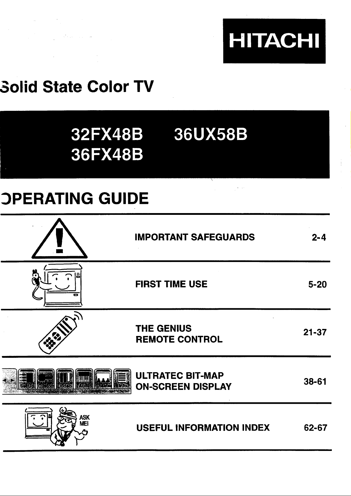
3olid State Color TV
_)PERATING GUID
IMPORTANT SAFEGUARDS
FIRST TIME USE
THE GENIUS
REMOTE CONTROL
ULTRATEC BIT-MAP
ON-SCREEN DISPLAY
2-4
5-20
21-37
38-61
K USEFUL INFORMATION INDEX 62-67
Page 2
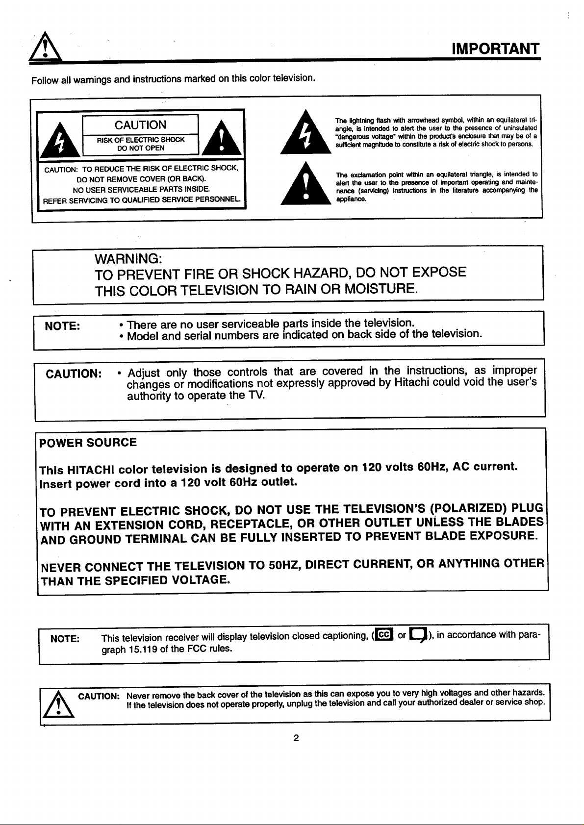
Followall warningsand instructionsmarked on thiscolor television.
IMPORTANT
CAUTION
RISK OF ELECTRIC SHOCK
DO NOT OPEN
CAUTION: TO REDUCE THE RISK OF ELECTRIC SHOCK,
DO NOT REMOVE COVER (OR BACK).
NO USER SERVICEABLE PARTS INSIDE.
REFER SERVICING TO QUAUFiED SERVICE PERSONNEL
WARNING:
TO PREVENT FIRE OR SHOCK HAZARD, DO NOT EXPOSE
THIS COLOR TELEVISION TO RAIN OR MOISTURE.
• There are no user serviceable parts inside the television.
I NOTE:
CAUTION:
• Model and serial numbers are indicated on back side of the television.
• Adjust only those controls that are covered in the instructions, as improper
changes or modifications not expressly approved by Hitachi could void the user's
authority to operate the TV.
The lightning flash with arrowhead symbol, within an equilateral tri-
angle, is intended to alert the user to the presence of uninsulated
=dangerous voltage" within the product's enclosure g_at may be of a
sufficient magnitude to constitute a dsk of electric shock to persons.
The exclamation point within an equilateral triangle, is intended to
alert the user to the presence of Important operating and maJnte-
nence (servicing) instructions in the literature accompanying the
appliance.
I
POWER SOURCE
This HITACHI color television is designed to operate on 120 volts 60Hz, AC current.
Insert power cord into a 120 volt 60Hz outlet.
TO PREVENT ELECTRIC SHOCK, DO NOT USE THE TELEVISION'S (POLARIZED) PLUG
WITH AN EXTENSION CORD, RECEPTACLE, OR OTHER OUTLET UNLESS THE BLADES
AND GROUND TERMINAL CAN BE FULLY INSERTED TO PREVENT BLADE EXPOSURE.
NEVER CONNECT THE TELEVISION TO 50HZ, DIRECT CURRENT, OR ANYTHING OTHER
THAN THE SPECIFIED VOLTAGE.
This television receiverwilldisplay television closed captioning, (r_ or I_), in accordance with para- I
I NOTE:
graph 15.119 of the FCC rules.
CAUTION:
Never remove the back cover of the television as thiscan expose you to very high voltages and other hazards. I
Ifthe television does not operate properly, unplugthe television and call your authorized dealer or service shop.
I
I
I
Page 3
SAFETY TIPS
IMPORTANT SAFEGUARDS
CAUTION: • Read all of these instructions.
• Save these instructions for later use.
• Follow all warnings and instructions marked
on the television.
Our reputation has been built on the quality, performance, and ease of service of HITACHI televisions.
Safety is also foremost in our minds in the design of these units.To help you operate these products properly, this section illustratessafety tips which
will be of benefit to you. Please read it carefully and apply the knowledge you obtain from it to the proper operation of your HITACHI television.
Please fill out your warranty card and mail it to HITACHI. This will enable HITACHI to notify you promptly in the improbable event that a safety
problem should be discovered in your product model.
FOR YOUR PERSONAL SAFETY
1. This television set is equipped with a
polarized allemating-oummt line ptug
(a plug having one blade wider than
the other.) This plug will fit into the
power outlet only one way. This is a
safely feature. If you are unable to
insert the plug fully into the outlet, try
reversing the i_u9. If the plug should
still fall to fit. contact your electrician
1o replace your obsolete outlet. Do
not defeat _ safety purpose OI the
peismed i_,ug.
2. When the power cord or plug is
damaged or frayed, unplug the
television from the wall outlet and
refer servicing to qualified service
personnel.
3. Do not overload wall outlets and
exlensidn cords as this can result in
fire or electric shock.
4. Do not allow anything to rest on or
roll over the power cord, and do not
place the television where the
power cord is subject to traffic or
abuse. This may result in a shock
or fire hazard.
5.
removing covers may expose you damp cloth for cleaning. Do not
television yourself as opening or wall outlet before cleaning. Use a
to dangerous voltage or other use liquid or aerosol cleaners.
Oono--o--h OOn --ro
hazards. Refer all servicing to
qualified service personnel.
Never push objects of any kind into
the televisiun's cabinet slots as they
may touch dangerous voltage points
or short out parts that could result in
a fire or eleotdc shock. Never spill
liquid of any kind on the television.
It the television has been dropped or
the cabinet has been damaged,
unplug the television from the wall
outlet and refer sewicing to qualified
service personnel.
If liquid has been spilled into the
television set. unplug it from the
wall outlet and refer service to
qualified service personnel,
DO not subject your television to
impact of any kind. Be careful not to
damage the picture tube sudace.
SAFETY POINTS YOU SHOULD KNOW ABOUT
YOUR HITACHI COLOR TELEVISION
11-1. Do not place the television on an
unstable cart, stand, or table. The
television may fall, causing
serious injury to • child or an
adult, and serious damage to the
appliance. Ueaonlywithacartor
stand recommended by the
manufacturer, or sold wi_ the
television. Wal or shelf mounting
should follow the menutacturer's
instructions, and should use a
mounting kit approved by the
manufacturer.
11-2. An applience and cart combination
should be moved with care.
Quick slops, excessive force, and
uneven sudaces may cause the
appliance end cart combination
to overturn.
PROTECTION AND LOCATION OF YOUR TELEVISION
12. Do not use the lelevision near
water, for example, near a bathtub,
washbowl, kitchen sink. or laundry
tub, in a wet basement, or near a
swimming pool. etc.
• Never expose the television to
rain or water. If the set has been
exposed to rain or water, unplug
television from wall outlet and
refer to qualified service person-
nel.
13. Choose a place where light
(artificial or sunlight) does not
shine directly on the screen.
14. Avoid dusty places. Accumulated
dust inside the chassis may cause
failure of the television when high
humidity persists.
15. The television has slots or openings
in the cabinet for ventilation
purposes which provide reliable
operation of the receiver and
protect the television from
overheating. These openings must
not be blocked or covered.
• Never cover the slots or openings
with cloth or other material.
3
Never block the bottom ventilation I_
slots of the television by placing it on
a bed, sofa, rug, etc.
over a radiator or heat register.
Nevor pl&ce the television near or _'f,'_*"*,'_
enclosure oniass proper ventilation
• Never p/ace the television in a built-in
is provided.
Page 4
PROTECTION AND LOCATION OF YOUR TELEVISION
16-1. If an outside antenna isconnected
to the television, be sure the
antenna system is grounded so as
to provide some protection against
voltage surges and betH-up static
charges. Section 810 of the
National Electrical Code, NFPA
No. 70-1975, provides information
with respect to proper grounding
of the mast and supporting
structure, grounding of the lea@in
wire to an antenna discharge unit,
size of grounding conductors,
location of antenna discharge unit
connection to grounding
electrode, and requirements for
the grounding electrode.
16-2. Nole to CATV system installer:
(Only for television with CATV
reception). This reminder is
provided to call the CATV system
insteller's attention to Article
820-40 of the NEC that provides
guidelines for proper grounding
and, in particular, specifies that
the cable ground shall be
connected to the grounding
system of the building, as close
to the point of cable entry as
practical.
EXAMPLE OF ANTENNA GROUNDING AS PER NATIONAL ELECTRICAL
CODE INSTRUCTIONS.
OPERATION OF YOUR TELEVISION
19. This television should be operat-
ed only from the type of power
source indicated on the marking o_ ,_/_
label. If you are not sure of the
type of power supply at your
home. consult your dealer or local
power company. For televisions
designed to operate from battery
power, refer to the operating
instructions.
T
NEeMlX_'W. B.ECTI_.K_
20.
If the television does not operate
normally by folowing the obeceting
instrucifons, unplug the telmCslen
from the wall outlet end refer *---"-_ €''%*"_
servicing to qualified service
personnel. Adjust only those
controls that are covered in the
insuuctk_ns as improper adjustment
of other controls may result in
damage and wilt often require
extensive work by • qualified
sennus technician to restore the
televislen to normal operetiork
SAFETY TIPS'
17. An outside antenna system should
not be located in the vicinity of
overhead power lines or other
electrical lights or power circuits.
or where it can fall into such power T _
lines or circuits. Wtlen installing an II ._x /'DO o'_1_
outside antenna system, extreme _ _,_o, I D J I
care should be taken to keep from _ -L--.._J-t.
touching such power lines or
circuits as contact with them might
be fatal.
18. For added protection for the
television during a lightning storm.
or when it is unused for long
periods of time, unplug it from the
wall outlet and disconnect antenna.
This will prevent damage due to
lightning and power-line surges.
21. If your television is to remain p_ __.
unused for a period of time. (such
as when going on a holiday), turn
the television OFF and unplug it
from the wall outlet.
IF THE TELEVISION DOES NOT OPERATE PROPERLY
22. If you are unable to restore
normal operation by following
the detailed procedure in your
operating instructions, do not
attempt any further adjustments.
Unplug the television and call
your dealer or service technician.
23. Whenever the television is
damaged or fails, or if there is a
distinct change in performance
that indicates a need for service.
unplug the television and hove it
checked by a qualified service
technician.
24. It is normal for some televisions to
make occasional snapping or
popping sounds, particularly v/nan
being turned on or off. if the
snapping or popping is continuous
or frequent, unplug the set and
consult your dealer or service
technician.
FOR SERVICING AND MODIFICATION
25. Do not use attachments not
recommended by the television
manu/ecturer as they may cause
hazards.
j,_ o 26. If replacement beds ere required, 27. Upon completion of any service or ._. ,_,
be sure the service technician has repairs Io the television, ask the
used replacement parts specified by service technician to perform
the manufacturer that have the routine safety checks to determine
same charectenstlos es the original that the television is in sate
bert. Unauthorized substitutions operatingsonditlon.
may result in fire. electric shock, or
olhe¢ hazards.
PICTURE CAUTIONS
Picture Burn Prevention
• Continuous on-screen displays such as video games, stock market quotations, computer generated graphics, and
other fixed (non-moving) patterns can cause permanent damage to television receivers. Such =PATTERN BURNS"
constitutemisuse and are NOT COVERED byyour HITACHI Factory Warranty.
• When using Picture-in-Picturefunction,the sub-pictureshouldnot be left permanently in one cornerof the screen or a
"PA'I-I'ERN BURN" may develop over a long period of time.
Public Viewing of Copyrighted Material
Public viewing of programs broadcast by TV stations and cable companies, as well as programsfrom other sources, may
require priorauthorizationfrom the broadcaster or owner of the video program material.
4
Page 5
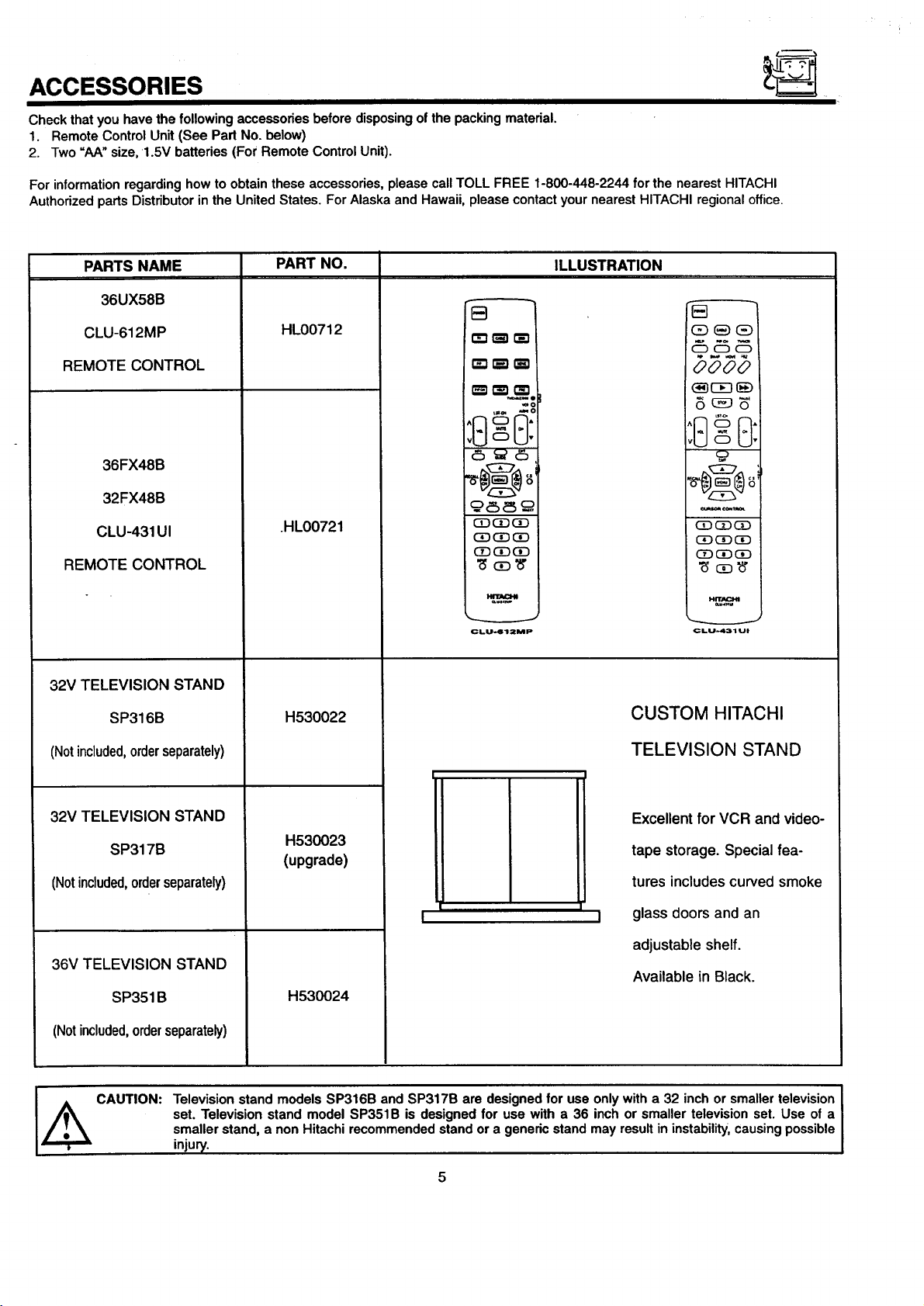
ACCESSORIES
Check that you have the following accessories before disposing of the packing material.
1. Remote Control Unit (See Part No. below)
2. Two "AA" size, 1.5V batteries (For Remote Control Unit).
For information regarding how to obtain these accessories, please call TOLL FREE 1-800-448-2244 for the nearest HITACHI
Authorized parts Distributorin the United States. For Alaska and Hawaii, please contact your nearest HITACHI regional office.
PARTS NAME
36UX58B
CLU-612MP
REMOTE CONTROL
36FX48B
32FX48B
CLU-431UI
REMOTE CONTROL
32V TELEVISION STAND
PART NO.
HL00712
.HL00721
.=.:,
(3_(3DGD
(3D(3_(3D
CD(3D(3D
CLU-612MP
ILLUSTRATION
0000
_ €_TP,m
CD CDCD
_CDCD
CLU-431U!
SP316B
(Notincluded,orderseparately)
32V TELEVISION STAND
SP317B
(Notincluded,orderseparately)
36V TELEVISION STAND
SP351B
(Notincluded,orderseparately)
Television stand models SP316B and SP317B are designed for use only with a 32 inch or smaller television
set. Television stand model SP351B is designed for use with a 36 inch or smaller television set. Use of a
J_Ik CAUTION:
smaller stand, a non Hitachi recommended stand or a generic stand may result in instability,causing possible
injury.
H530022
H530023
(upgrade)
H530024
CUSTOM HITACHI
TELEVISION STAND
Excellent for VCR and video-
tape storage. Special fea-
tures includes curved smoke
glass doors and an
I
adjustable shelf.
Available in Black.
Page 6
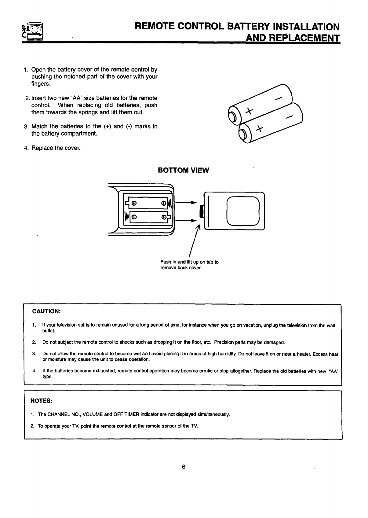
REMOTE CONTROL BATTERY INSTALLATION
1. Open the battery cover of the remote control by
pushing the notched part of the cover with your
fingers.
2. Insert two new "AA" size batteries forthe remote
control. When replacing old batteries, push
them towards the springs and lift them out.
3. Match the batteries to the (+) and (-) marks in
the battery compartment.
4. Replace the cover.
AND REPLACEMENT
BOTTOM VIEW
Push in and lift up on tab to
remove back cover.
CAUTION:
1.
If your television set is to remain unused for a long period of time, for instance when you go on vacation, unplug the television from the wall
outlet.
2.
Do not subject the remote control to shocks such as dropping it on the floor, etc. Precision parts may be damaged.
3.
Do not allow the remote control to become wet and avoid placing it in areas of high humidity. Do not leave it on or near a heater. Excess heat
or moisture may cause the unit to cease operation.
4.
If the batteries become exhausted, remote control operation may become erratic or stop altogether. Replace the old batteries with new "AA"
type.
NOTES:
1. The CHANNEL NO., VOLUME and OFF TIMER indicator are not displayed simultaneously.
2. Tooperate your TV, point the remote control at the remote sensor of the TV.
Page 7
HOW TO SET UP YOUR NEW HITACHI COLOR TV
ANTENNA
Unless your TV is connected to a cable TV system or to a centralized antenna system, a good outdoor color TV antenna is
recommended for best performance. However, if you are located in an exceptionally good signal area that isfree from interferenceand
multipleimage ghosts, an indoor antenna may be sufficient.
LOCATION
Select an area where sunlight or bright indoor illuminationwill not fall directly on the picture screen. Also, be sure that the location
selected allows a free flow of air to and from the perforated back cover of the set.
To avoid cabinet warping, cabinet color changes, and increased chance of set failure, do not place the TV where temperatures can
become excessively hot, for example, in direct sunlightor near a heating appliance, etc.
VIEWING
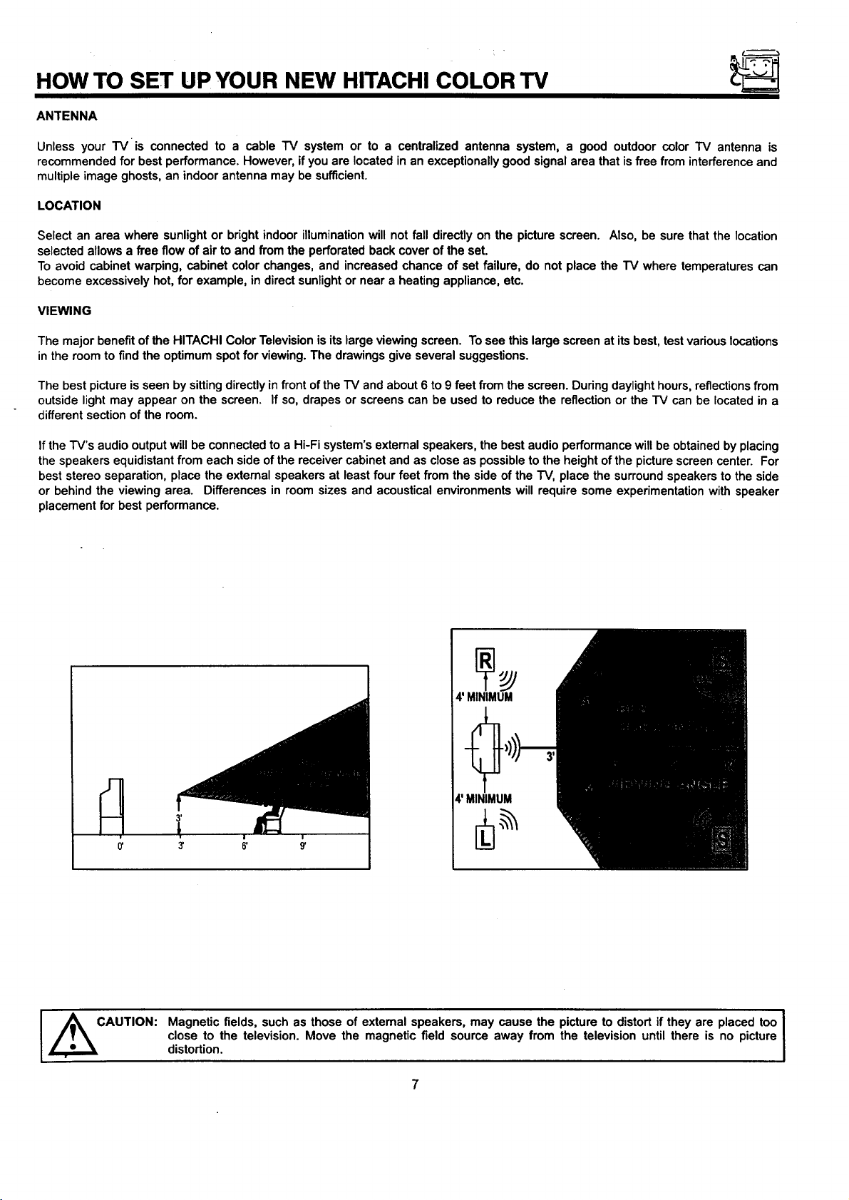
The major benefit of the HITACHI Color Television is its large viewing screen. To see this large screen at its best, test various locations
in the room to find the optimum spot for viewing. The drawings give several suggestions.
The best picture is seen by sitting directly in front of the "IV and about 6 to 9 feet from the screen. During daylight hours, reflections from
outside light may appear on the screen. If so, drapes or screens can be used to reduce the reflection or the "IV can be located in a
different section of the room.
If the "FV'saudio output will be connected to a Hi-Fi system's external speakers, the best audio performance will be obtained by placing
the speakers equidistant from each side of the receiver cabinet and as close as possible to the height of the picture screen center. For
best stereo separation, place the external speakers at leastfour feet from the side of the "IV, place the surroundspeakers to the side
or behind the viewing area. Differences in room sizes and acoustical environments will require some experimentation with speaker
placement for best performance.
I ,_CAUTION:
4' MINIMUM
4' MINIMUM
Magnetic fields, such as those of external speakers, may cause the picture to distort if they are placed too
close to the television. Move the magnetic field source away from the television until there is no picture
distortion.
I
Page 8
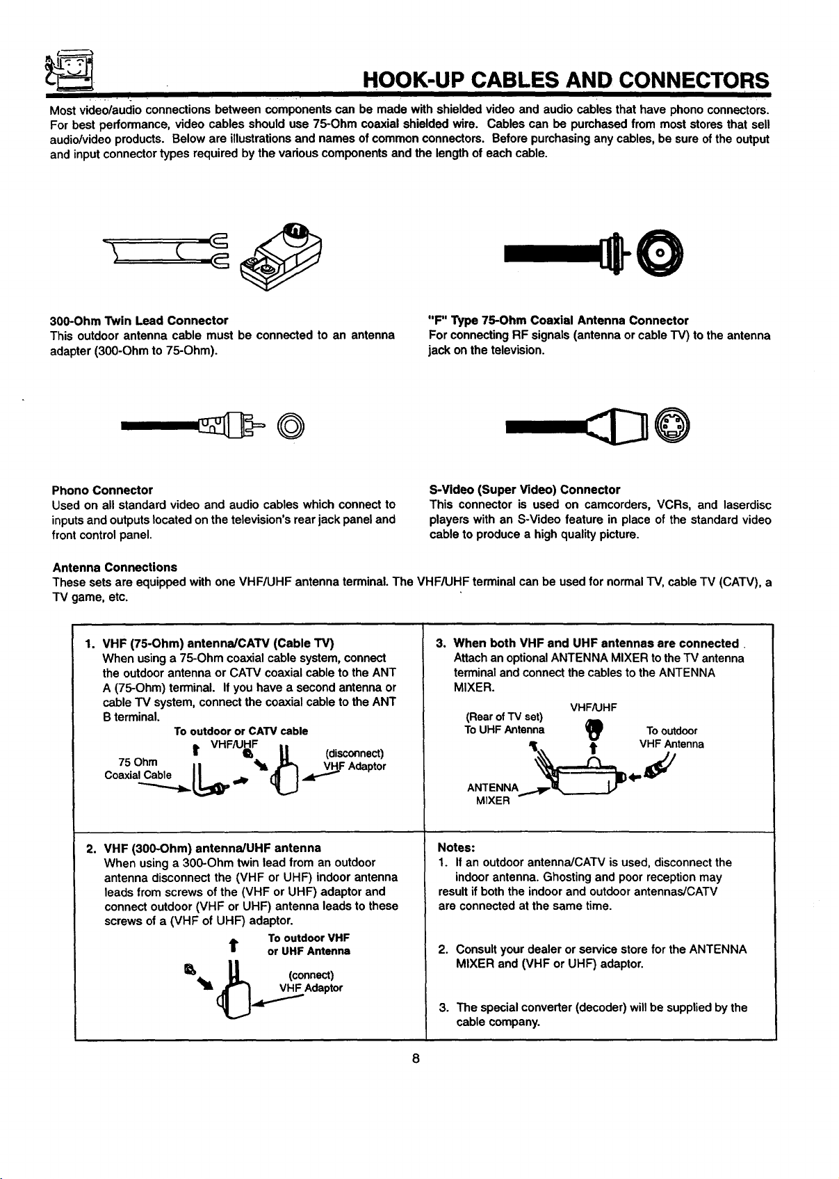
HOOK-UP CABLES AND CONNECTORS
Most video/audio connections between components can be made with shielded video and audio cables that have phono connectors.
For best performance, video cables should use 75-Ohm coaxial shielded wire. Cables can be purchased from most stores that sell
audio/videoproducts. Below are illustrations and names ofcommon connectors. Before purchasing any cables, be sure of the output
and input connector types required bythe various components and the length of each cable.
300-Ohm Twin Lead Connector
This outdoor antenna cable must be connected to an antenna
adapter (300-Ohm to 75-Ohm).
Phono Connector
Used on all standard video and audio cables which connect to
inputsand outputslocated on the television's rear jack panel and
front control panel.
"F" Type 75-Ohm Coaxial Antenna Connector
For connectingRF signals (antenna or cableTV) to the antenna
jack on the television.
S-Video (Super Video) Connector
This connector is used on camcorders, VCRs, and laserdisc
players with an S-Video feature in place of the standard video
cable to produce a high quality picture.
Antenna Connections
These sets are equipped with one VHF/UHF antenna terminal. The VHF/UHF terminal can be used for normal TV, cable TV (CATV), a
TV game, etc.
1.
VHF (75-Ohm) antenna/CAW (Cable TV)
When using a 75-Ohm coaxial cable system, connect
the outdoor antenna or CATV coaxial cable to the ANT
A (75-Ohm) terminal. If you have a second antenna or
cableTV system, connect the coaxial cable to the ANT
B terminal.
Tooutdoor or CATV cable
3. When both VHF and UHF antennas are connected
Attachan optionalANTENNA MIXER tothe TV antenna
terminal and connectthe cables to the ANTENNA
MIXER.
(Rearof TV set)
ToUHF Antenna II_
VHF/UHF
To
outdoor
L VHFAJHF ,,
75Ohm I I Q,hlL _L t (disconnect)
C°axia_...jb= LI,_ _@, (_L.J ._F Adapt°r
ANTENNA
.,,._.__ 4"_VHFAntenna
MIXER
2. VHF (300-Ohm) antennaiUHF antenna
When using a 300-Ohm twin lead from an outdoor
antenna disconnect the (VHF or UHF) indoor antenna
leads from screws of the (VHF or UHF) adaptor and
connect outdoor (VHF or UHF) antenna leads to these
screws of a (VHF of UHF) adaptor.
To outdoor VHF
t or UHF Antenna
_llL _ (connect)
_.,_._Adaptor
Notes:
1. If an outdoor antenna/CATV is used, disconnect the
indoor antenna. Ghosting and poor reception may
result if both the indoor and outdoor antennas/CATV
are connected at the same time.
2. Consultyour dealer or service store for the ANTENNA
MIXER and (VHF or UHF) adaptor.
3. The special converter (decoder) willbe supplied by the
cable company.
Page 9
FRONT PANEL CONTROLS FOR 32FX48B
• FRONT VIEW
L J _ I Iooeeocn| • I
I
HOW TO OPEN THE DOOR
I m
1. Push on "_"
2. Pull the door toward the front to open it.
FRONT INPUT JACKS
0 0 0
I I INPUT3 I J
(_) Video:3 Input-_
0 @ ®
Button Butbm Burns
Volume
VOL- VOI.* C_ Oe.
0000000
MENU--I I I I I I
Exrr.-----J I I I I
.4 • • •
CURSOR
O
Dual Tuner PIP I
(_) RemoteControl
InfraredSensor
See pages 25 and 26 for
MENU, CURSOR, and EXIT
buttonoperations.
A detailed explanation of the circled numbers ison page 11.
Page 10
FRONT PANEL CONTROLS FOR 36UX58B AND 36FX48B
For 36UX58B Only
/.1111111/IBII
@ @ ® ®
InmUF_xit Volume Channel
Button Buttons Butto_
--1 _-I r-h I
Vvol.& • ot •
O00QO00
I
MENUEX=r ,4 I_ • •
MENUJ I I I I I
CURSOR
FRONT VIEW
r
I Dual Tuner PIP (O)',-- .,_.,,,_
Remote Control
Infrared Sensor
See pages 25 and 26 for
MENU, CURSOR, and EXIT
button operations.
0000 0 O0
A detailed explanation of the circled numbers is on page 11.
I NOTE: (e)°SOl, INI} RErRIEVAL _ is for MODEL 36UX58B only.
10
FRONTINPUTJACKS
i
Page 11
FRONT PANEL JACKS AND CONNECTIONS
I I
INPUT/EXIT button
Press this buttonto selectthe currentantenna source of VIDEO: 1,2, 3. Your selection is shown in the top rightcomer ofthe screen.
This button also serves as the EXIT buttonwhen in MENU mode.
VOLUME Level
Press these buttons for your desired sound level. The volume level will be displayed on the TV screen.
CHANNEL Selector
Press these buttons until the desired channel appears in the top right corner of the TV screen.
POWER Button
Press this button to tum the TV on or off.
NOTE:
®
®
I NOTE: Frontpanel control CURSOR operation will not appear the FAMILY FAVORITES channel function. I
Your HITACHI TV will appear to be turned off ifthere is no video inputwhen VIDEO: 1, 2, or 3 isselected. If you have
no inputto VIDEO: 1, 2, or 3, pressthe INPUT button until the normal broadcast picture appears. (See page 25.)
If the picture does not appear, the power is OFF.
REMOTE CONTROL INFRARED Sensor
Point your remote control at this area when selecting channels, adjusting volume, etc.
FRONT INPUT JACKS
Use these audio/video jacks for a quick hook-up from a camcorder or VCR to instantlyview your favorite show or new recording.
Press the INPUT button until VIDEO:3 appears in the top right corner of the TV screen. If you have mono sound, insert the audio
cable into the left channel jack.
11
Page 12
FRONT PANEL JACKS AND CONNECTIONS
The front panel jacks are provided as a convenience to allow you to easily connect a camcorder or VCR as shown in the following
examples:
Video Camera
Video Camera
0
OUTPUT
_ OUTPUT
Insert audio cable
into left channel
for mono sound
INPUT
INPUT
°°°
/
/
/ /
I NOTE:
t
OO
NPUT f
S-VHS V L R
I°°°° Y
(BackolVCR)
Completely insert connection cord plugs when connectingto front panel jacks. If you do not, the picture that is played
back may be abnormal.
OUTPUT |
12
Page 13
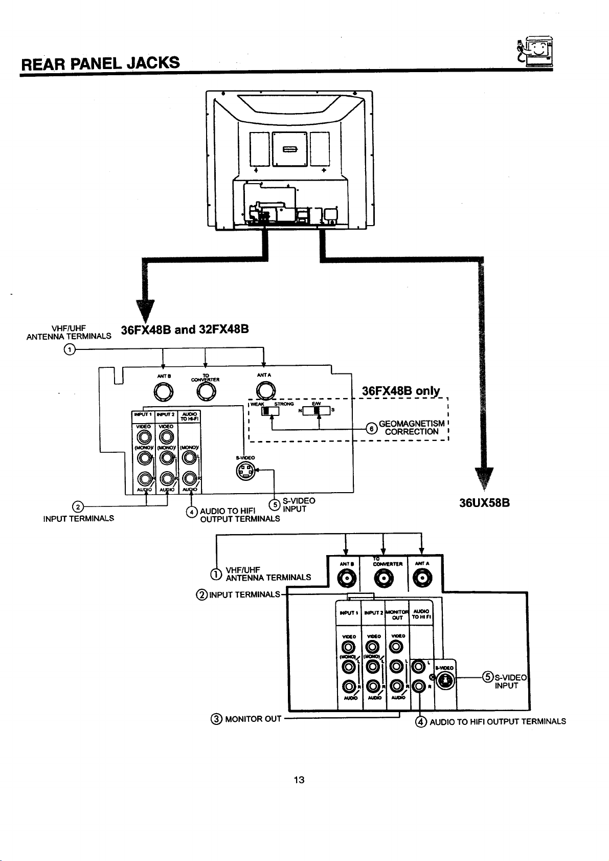
REAR PANEL JACKS
Ili.o]11
4 ÷
VHF/UHF
ANTENNA TERMINALS
(9
Q
INPUT TERMINALS
36FX48B and 32FX48B
lJ
/INT IJ TO ANlrA
o _ _Q
I
I I
" _ 8-VIDEO
AUDIO TO HIFI _,_ INPUT
(
OUTPUT TERMINALS
INPUT TERMINALS
• I WE,AK STRONG
L._
36FX48B only_,
(_) GEO_GNETISM J
CORRECTION z
I, I
I
I
I
r
36UX58B
(_) MONITOR OUT '
13
1_;16°16°1
i t=oz_/.ll_zl l
I
IOflOilOil<
INPUT
/o_ .1o4 '1,
I
) AUDIO TO HIFI OUTPUT TERMINALS
Page 14
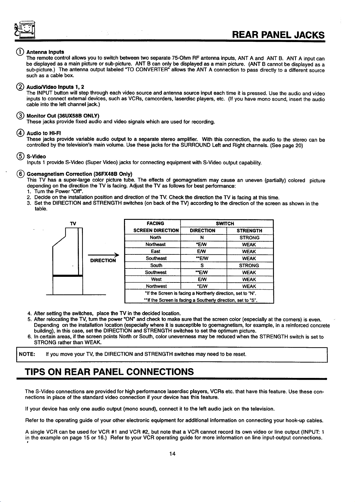
REAR PANEL JACKS
(_ Antenna Inputs
The remote control allows you to switch between two separate 75-Ohm RF antenna inputs, ANT A and ANT B. ANT A inputcan
be displayed as a main picture or sub-picture. ANT B can only be displayed as a main picture. (ANT B cannot be displayed as a
sub-picture.) The antenna output labeled =TOCONVERTER" allows the ANT A connection to pass directly to a different source
such as a cable box.
O Audio/Video Inputs 1, 2
The INPUT button will step through each video source and antenna source input each time it is pressed. Use the audio and video
inputs to connect extemal devices, such as VCRs, camcorders, laserdisc players, etc. (If you have mono sound, insert the audio
cable into the left channel jack.)
(_) Monitor Out (36UX58B ONLY)
These jacks provide fixed audio and video signals which are used for recording.
(_) Audio to HI-FI
These jacks provide variable audio output to a separate stereo amplifier. With this connection, the audio to the stereo can be
controlledby the television's main volume. Use these jacks for the SURROUND Left and Right channels. (See page 20)
(_ S-Video
Inputs 1 provide S-Video (Super Video) jacks forconnecting equipment with S-Video outputcapability.
(_ Goemagnetism Correction (36FX48B Only)
This TV has a super-large color picture tube. The effects of geomagnetism may cause an uneven (partially) colored picture
depending on the directionthe TV isfacing. Adjust the TV as follows for best performance:
1. Turn the Power uO_.
2. Decide on the installation position and directionof the TV. Check the directionthe TV is facing at this time.
3. Set the DIRECTION and STRENGTH switches (on back of the TV) according to the directionof the screen as shown in the
table.
FACING
SCREEN DIRECTION
North
Northeast
East
DIRECTION
4. After setting the switches, place the TV in the decided location.
5. After relocating the TV, tum the power =ON" and checkto make sure that the screen color (especially at the corners) is even.
Depending on the installation location (especially where it is susceptible to goemagnetism, for example, in a reinforced concrete
building), in this case, set the DIRECTION and STRENGTH switches to set the optimum picture.
6. In certain areas, if the screen points North or South, color unevenness may be reduced when the STRENGTH switch is set to
STRONG rather than WEAK.
I NOTE: If you move your TV, the DIRECTION and STRENGTH switches may need to be reset. I
Southeast
South
Southwest
West
Northwest
*ifthe Screenisfacing aNortherlydirection,setto"N'.
**IftheScreenisfacing a Southerlydirection,set to"S'.
DIRECTION
*E/W
E/W
**F.JVV
**E/W
*F_AN
N
s
E/W
SWITCH
STRENGTH
STRONG
WEAK
WEAK
WEAK
STRONG
WEAK
WEAK
WEAK
TIPS ON REAR PANEL CONNECTIONS
The S-Video connections are provided for high performance laserdisc players, VCRs etc. that have this feature. Use these con-
nections in place of the standard video connection if your device has this feature.
I
If your device has only one audio output (mono sound), connect it to the left audio jack on the television.
Refer to the operating guide of your other electronic equipment for additional information on connecting your hook-up cables.
A single VCR can be used for VCR #1 and VCR #2, but note that a VCR cannot record its own video or line output (INPUT: 1
in the example on page 15 or 16.) Refer to your VCR operating guide for more information on line input-output connections.
14
Page 15
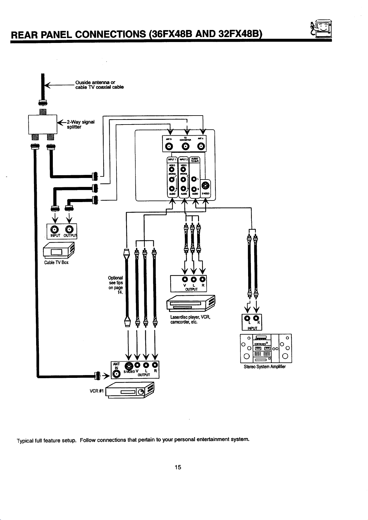
REAR PANEL CONNECTIONS 136FX48B AND 32FX48B I
IJ
Ouside antenna or
cable "IV coaxial cable
W
l [,_-2-Way signal
J " splitter
_I
CableTVBox
o_ Iol
IF OO
StereoSystemAmpli6er
1_1o _v_ °L
!
Typicalfull feature setup. Follow connections that pertain to your personal entertainment system.
15
Page 16
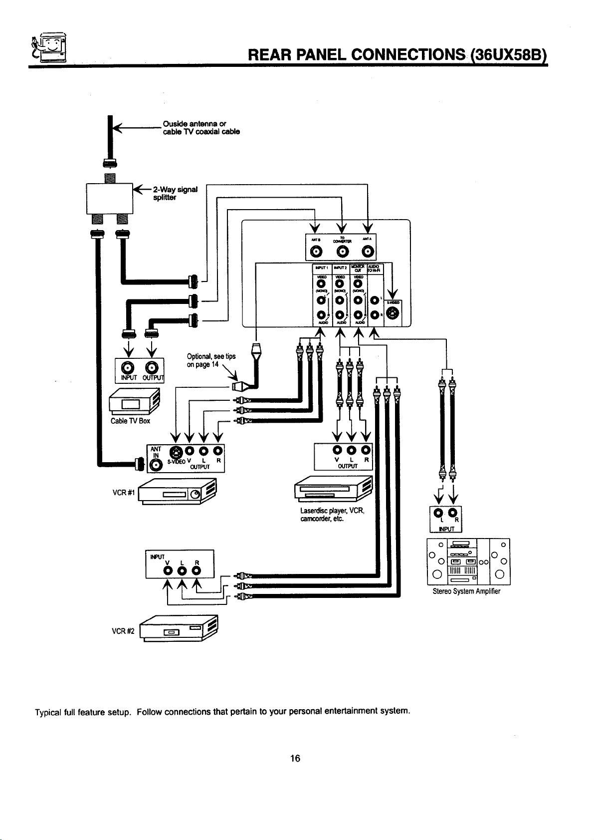
I
Ouside antenna or
cable TV coaxial cable
REAR PANEL CONNECTIONS 136UX58B )
I
l _-_ 2-Way signal
I - splitter
onpage14 '_J I
-'{_1
CableTVBox
VCR#1 : ;
I =
LaSermc0d_er,Player.VCR,
VCR#2 I_ _ '-"_
Typicalfull feature setup. Follow connectionsthat pertain to your personal entertainment system.
I
16
IOo ooLOol
o_ IOl
StereoSystemAmplifier
Page 17
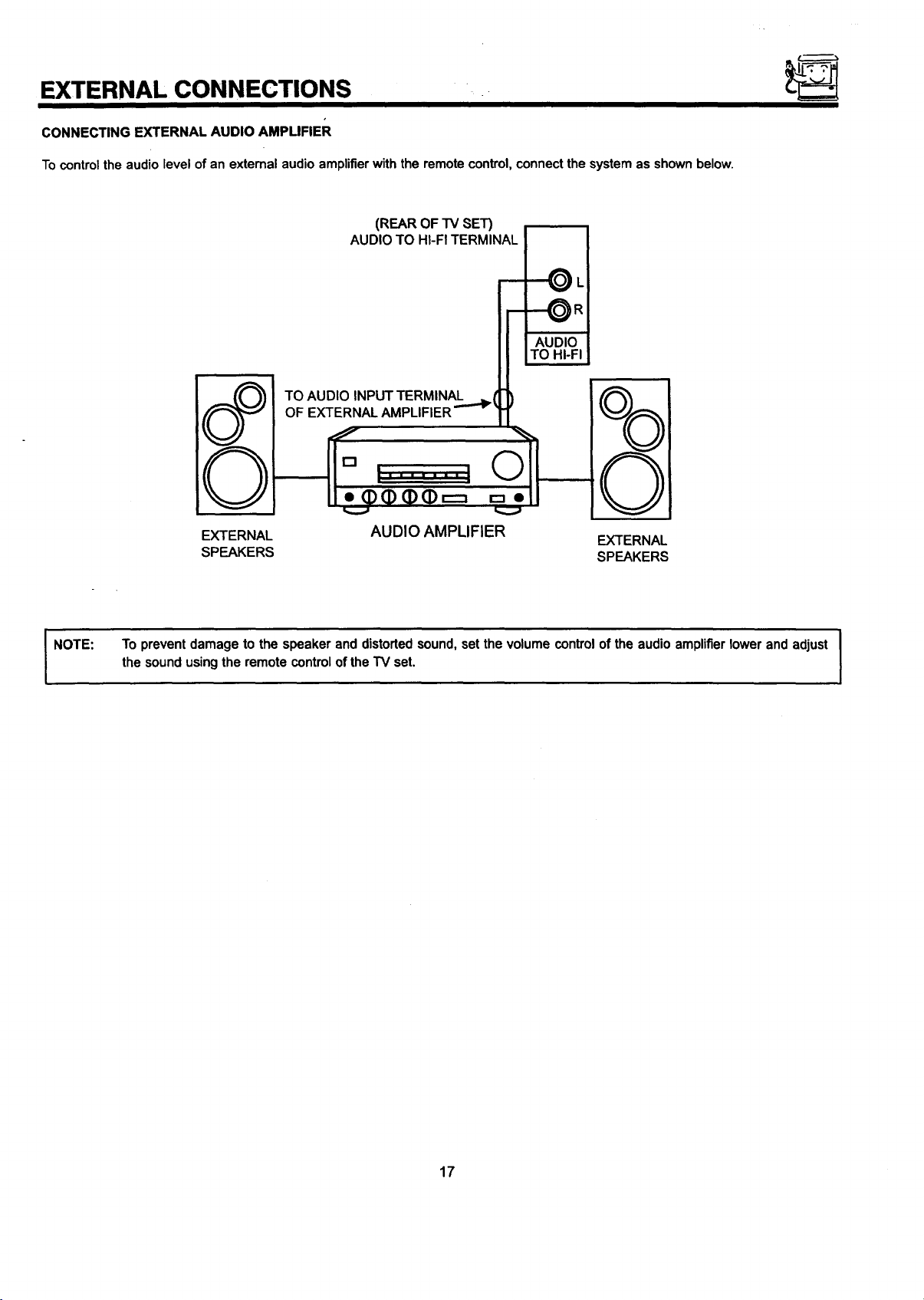
EXTERNAL CONNECTIONS
CONNECTING EXTERNAL AUDIO AMPLIFIER
Tocontrol the audio level of an external audio amplifierwith the remote control, connect the system as shown below.
(REAROF TV SET)
AUDIOTO HI-FITERMINAL
-'--_L
I
AUDIO
TO HI-FI
TO AUDIO INPUT TERMINAL
OF
©
NOTE:
EXTERNAL
SPEAKERS
To prevent damage to the speaker and distorted sound, set the volume control of the audio amplifier lower and adjust
the sound using the remote controlof the TV set.
AUDIO AMPLIFIER
EXTERNAL
SPEAKERS
17
Page 18
CONNECTING EXTERNAL VIDEO SOURCES
The exact arrangement you use to connect the VCR, camcorder, laserdiscplayer to yourTV set isdependent on the model and features
of each component. Check the owner's manual of each component for the location of video and audio inputs and outputs.
The followingconnectiondiagrams are offered as suggestions. However, you may need to modifythem toaccommodate your particular
assortment of components and features. For best performance, video and audio cables should be made from coaxial shielded wire.
Before Operating External Video Source
The input mode ischanged every time the INPUT buttonispressed as shown below. Connect an extemal sourceto the INPUT terminal,
then press the INPUT button as necessary to view the input source. (See page 25.)
INPUT MODE SELECTION ORDER
(Antenna)
(Input)
VIDEO
NOTE:
CONNECTING A MONAURAL AUDIO VCR OR LASERDISC PLAYER
1. Connect the cable from the VIDEO OUT of the VCR or the laserdiscplayer to the INPUT (VIDEO) jack on the TV set below.
2. Connect the cable from the AUDIO OUT ofthe VCR or the laserdisc player to the INPUT (MONO)/L(AUDIO) jack.
3. Pressthe INPUT button to view the program from the VCR or the laserdiscplayer. The VIDEO mode disappears automatically after
approximately eight seconds.
4. Press the INPUT button to return to the previous channel.
When the TV is set to VIDEO and a video signal is not received from the VIDEO INPUT JACK on the jack panel ofthe J
TV (i.e., VCR/laserdisc player, etc. is not connected or the video device is OFF), the screen will be gray-blue.
VCR
TV INPUT
TERMINAL
VIDEOOUT AUDIOOUT
INPU'I
I® ®1
VIDEO
[lr_',\
\\_.JJl
IMONO_
I
I
AUDIO
=
18
Page 19
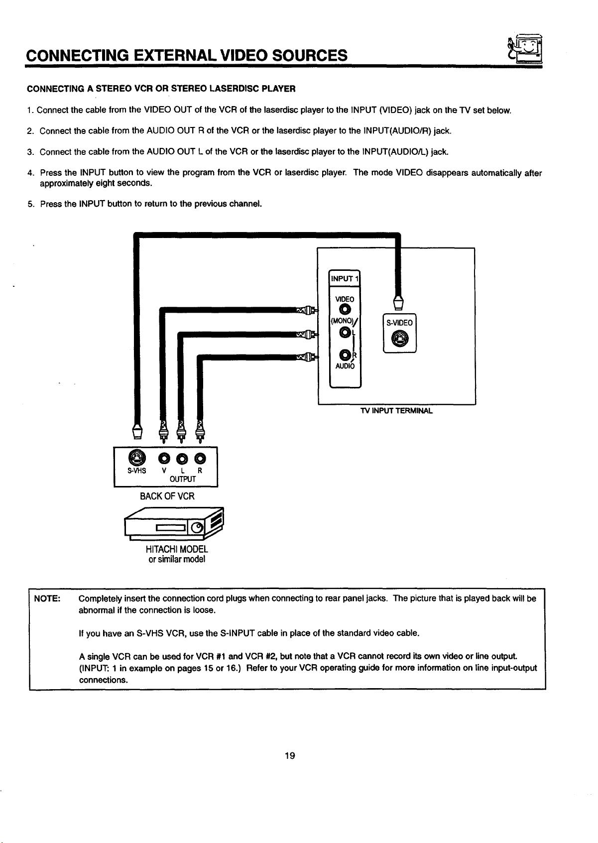
CONNECTING EXTERNAL VIDEO SOURCES
CONNECTING A STEREO VCR OR STEREO LASERDISC PLAYER
1. Connect the cable from the VIDEO OUT of the VCR of the laserdisc player to the INPUT (VIDEO) jack on the TV set below.
2. Connect the cable from the AUDIO OUT R of the VCR or the laserdiscplayer to the INPUT(AUDIO/R) jack.
3. Connect the cable from the AUDIO OUT L of the VCR or the laserdisc player to the INPUT(AUDIO/L) jack.
4. Press the INPUT button to view the program from the VCR or laserdisc player. The mode VIDEO disappears automatically after
approximately eight seconds.
5. Press the INPUT button to return to the previous channel.
INPUT11
VIDEO
O
(MONOI/oL
NOTE:
AUDIO
TV INPUT TERMINAL
000
S-VHS V L R
OUTPUT
BACKOF VCR
HITACHI MODEL
orsimilarmodel
Completely insert the connection cord plugswhen connectingto rear panel jacks. The picture that is played back will be
abnormal if the connection is loose.
If you have an S-VHS VCR, use the S-INPUT cable in place of the standard video cable.
A single VCR can be used for VCR #1 and VCR #2, but notethat a VCR cannot record its own video or lineoutput.
(INPUT: 1 in example on pages 15 or 16.) Refer to your VCR operating guide for more information on line input-output
connections.
19
Page 20
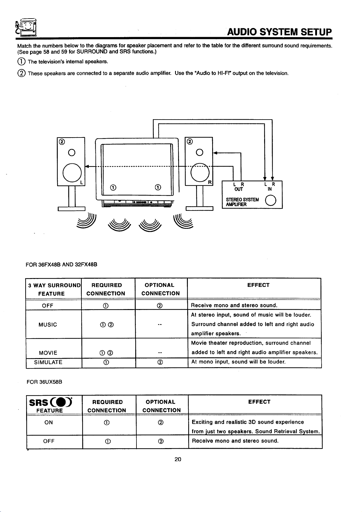
AUDIO SYSTEM SETUP
Match the numbers below to the diagrams for speaker placement and refer to the table for the different surroundsound requirements.
(See page 58 and 59 for SURROUND and SRS functions.)
0 The television's internal speakers.
(_ These speakers are connected to a separate audio amplifier. Use the =Audio to HI-FI" output on the television.
l
®
®
0
L '4"_
II
L J
3
FOR 36FX48B AND 32FX48B
3 WAY SURROUND
FEATURE
OFF
MUSIC
MOVIE
SIMULATE
CONNECTION
L'-' .... " ' '__!'
REQUIRED
O
O®
OPTIONAL
CONNECTION
0
OUT IN
LR
STEREOSYSTEM O
I
0
.°
Receive mono and stereo sound.
At stereo input, sound of music will be louder.
Surround channel added to left and right audio
amplifier speakers.
Movie theater reproduction, surround channel
added to left and right audio amplifier speakers.
At mono input, sound will be louder.
AMPUFIER
EFFECT
FOR 36UX58B
sns(e
FEATURE
ON
OFF
REQUIRED
CONNECTION
O
O
OPTIONAL
CONNECTION
@
EFFECT
Exciting and realistic 3D sound experience
from just two speakers. Sound Retrieval System.
Receive mono and stereo sound.
20
Page 21
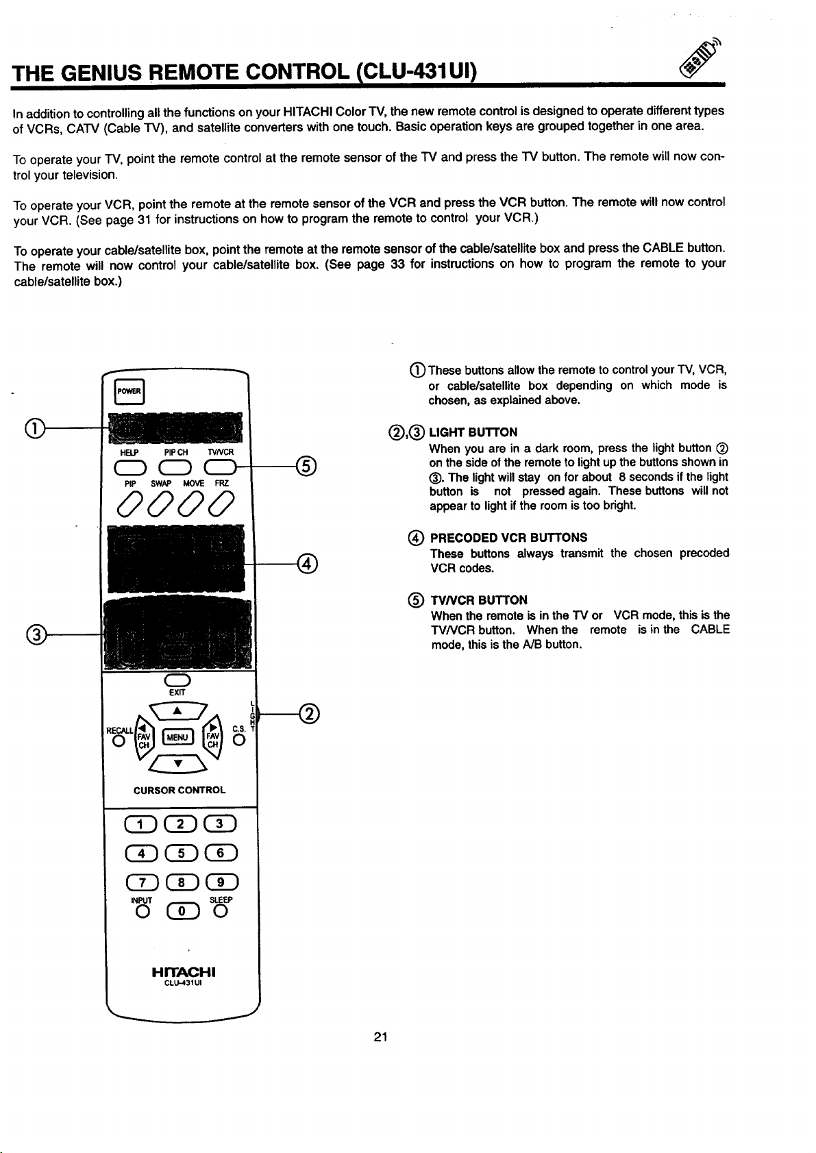
THE GENIUS REMOTE CONTROL CLU-431UI)
In addition to controlling all the functionsonyourHITACHIColor"IV,the new remotecontrolisdesignedto operatedifferent types
ofVCRs, CATV (Cable TV), and satelliteconverterswithone touch.Basicoperationkeys are groupedtogetherin onearea.
To operate your TV, point the remote control at the remote sensor of the TV and press the TV button. The remote will now con-
trol your television.
To operateyourVCR, pointthe remote at the remotesensorof the VCR and pressthe VCR button.The remotewillnowcontrol
yourVCR. (See page 31 for instructionson howto programthe remoteto controlyourVCR.)
To operateyourcable/satellitebox,point the remote at the remotesensorof the cable/satellitebox and press the CABLE button.
The remote will now controlyour cable/satellitebox. (See page 33 for instructionson how to program the remote to your
cablelsatellitebox.)
(_) These buttons allow the remote to controlyour TV, VCR,
or cable/satellite box depending on which mode is
chosen, as explained above.
LIGHT BUTTON
HELP PIPCH WNCR
®
PIP SWAP MOVE FRZ
0000
When you are in a dark room, press the light button (_)
on the side of the remote to light up the buttons shown in
(_). The light will stay on for about 8 seconds if the light
button is not pressed again. These buttons will not
appear to light if the room is too bright.
0
EXIT
CURSOR CONTROL
Ci) C!)
INPUT SLEEP
O (!i) 0
(_ PRECODED VCR BUTrONS
These buttons always transmit the chosen precoded
VCR codes.
TV/VCR BUTTON
®
When the remote is in the TV or VCR mode, this is the
TV/VCR button. When the remote is in the CABLE
mode, this is the A/B button.
HITACHI
CLU_31UI
J
21
Page 22

THE GENIUS REMOTE CONTROL (CLU-612MP)
In addition to controlling all the functions on your HITACHI color
television, the remote control is designed to operate different
types of VCRs, CATV (Cable TV)/satellite converters, and audio
equipment with one touch. Basic operation keys are grouped
together in one area. All other controls are separated from them
and arranged in MULTI-PAGE sections, with a display that can
be switched to cover any of the three pages. Functions are
arranged and properly categorized into windows, making opera-
tion simple when multiple functions are to be controlled.
To operate your TV, slide the MULTI-PAGE select switch on the
side of the remote to TV/CABLE/DSS mode. Press the TV button
and the remote will now control your television.
To operate your cable box, slide the MULTI-PAGE select switch
on the side of the remote to TV/CABLE/DSS mode. Press the
CABLE button and the remote will now control your cable box.
(See page 34 for instructions on how to program the remote to
control your cable box.)
To operate your satellite box, slide the MULTI-PAGE select
switch on the side of the remote to TV/CABLE/DSS mode. Press
the DSS button and the remote will nowcontrol your satellite box.
(See page 34 for instructions on how to program the remote to
control your satellite box.)
AUDIO O
To operate your VCR, slide the MULTI-PAGE select switch onthe
side of the remote to VCR mode. The remote will now control
your VCR. (See page 32 for instructionson how to program the
remote to control your VCR.)
To operate your audio equipment, slide the MULTI-PAGE select
switch on the side of the remote to AUDIO mode. Press the
button which corresponds to the component you would like to
control (AMP, CD, TAPE). The remote will now controlyour audio
equipment. (See page 35 for instructionson how to program the
remote to controlyour audio equipment.)
O MULTI-PAGE SELECT SWITCH
This selects the button layout of the multi-page section of
the remote control.
(_ MULTI-PAGEBUTTONS
These buttonschangefunctionsas shownonpage23.
O LIGHT BUTTON
When you are in a dark room, press this button on the side
of the remote to light up the buttons shown in (_. The light
will stay on !or about eight seconds ifthe lightbutton is not
pressed again. These buttons will not appear to light if the
room istoo bright.
INPUT SLEEP
0 0
(_) These buttons light up when light button(_) is pressed.
O These buttons allow the remote to control your TV, VCR, or
cable/satellite box depending on which mode is chosen, as
explained above.
(_ HELP BUTTON
Press this button if help is needed to change menu settings,
and our context sensitive help system will provide explana-
tions and/or directions for whatever function your cursor is
, on at that time.
HITACHI
CLU-612MP
22
Page 23

MULTI-PAGE WINDOWS ICLU-612MP)
"rv/cABLEi1DSS •
vcRO
Auo,oO
When "TV/CABLF_.JDSS"is set.
SELECT
"SWITCH
"rv/CABLE/DSS 0
AUDIO 0
When "VCR" is set.
VCR•
__ SELECT
WITCH
TV/CABLF.JDSS O
VCR O
AUDIO
When "AUDIO" is set.
23
SELECT
_-----SWITCH
Page 24

_;_ HOW TO USE THE GENIUS REMOTE TO CONTROL YOUR TV
A detailed explanation ofthe circled numbers follows on pages 25 to 26.
@
HELP PIPCH TVNCR
CD CD CD
®
INFO 0
GUIDE
TVICABLE/DSS
REC PAUSE
0
EXIT
C.S.
0
CURSOR CONTROL
®
®
L
]
@
®
- INPUT
0
HITACHI
CLU-612MP
24
HITACHI
CLU-431UI
SLEEP
0
J
@
Page 25

HOW TO USE THE REMOTE TO CONTROL YOUR TV
(_ TV POWER Button
Press this button to turn the TV set on or off. If a Special Event Reminder isset, it willbe displayedwhen the TV isfirstturned on.
(See page 60.)
Q SLEEP Button
Press this button to display the SLEEP TIMER in the lower left corner of the screen. Every subsequent press of this button will
add 15 minutes to the timer, up to a maximum of three hours.
O MENU, CURSOR Buttons
All On-Screen Display features can be set or adjusted by usingthese buttons.
The MENU button willstart the On-Screen Display.
The CURSOR buttons will highlight functions or adjust and set different features when MENU is pressed.
The CURSOR button will move PIP positionwhen PIP is on.
CURSOR buttonswill also give you access to FAMILY FAVORITE On-Screen Display.
_ CHANNEL SELECTOR Buttons
Enter two or three numbers to select channels. Enter "0" first for channels 1 to 9. For channels 100 and above, press the =1"
button and wait for two seconds before pressing the last two digits of the channel.
Channel selection may also be performed by pressing CH up (&) or down (V).
You may also use these buttons for channel scanning. Press and hold the CH up (A) or down (Y) buttons and the TV will start
quicklyscanning through the channels. Release the CH up (A) or down (Y) buttonswhen the TV scans to the channel you wishto
watch and the TV will tune to that channel.
I NOTE: " The TV may not receive some channels ifyou are notin the correct SIGNAL SOURCE mode. (See page 42.) I
(_ INPUT Button
The INPUT button will select between both antenna signals and the four sets of video inputjacks each time the buttonis pressed.
Ifthe Picture-in-Picture is on, the INPUT button will select between four sets of video input jacks and both antenna sourceswhen
main channel ischosen with the PIP CH button. If the sub-picture is chosen, the INPUT buttonwill select between the four sets of
video inputjacks and the ANT A source (ANT B source cannot be displayed as a PIP sub-picture.)
INPUT
INPUT
INPUT
INPUT
©
INPUT
INPUT
25
Page 26

HOW TO USE THE REMOTE TO CONTROL YOUR TV
(_ VOLUME, MUTE Buttons
Press the VOLUME up ( • ) or down ( • ) button untilyou obtain the desired sound level.
To turn the sound off instantly to answer the telephone, etc., press the MUTE button. Press the MUTE button again or press the
VOLUME Up ( • ) button to restore the sound.
O LAST CHANNEL (LST-CH) Button
Use this button to select between the lasttwo channels viewed. (Good for watching two sporting events, etc.)
LST-CH
(_) PICTURE-IN-PICTUR E
See separate section on page 28 for a description.
(_) LIGHT Button
When you are in a dark room, press this buttonto lightup the volume and channel buttons. The lightwill stay on for about eight
seconds if no buttons are pressed. The buttonswill not appear to light ifthe room is too bright.
(_) PIP CH Button
Use the PIP CH button to select between main picture and sub-picture tuning. The cyan background on the channel number will
indicate which channel is being controlled.
(_) EXIT Button
When in MENU mode, this buttonwill exit all On-Screen Displays.
(_ COMMERCIAL SKIP Button
Press this button when no menu is displayed to enable the COMMERCIAL SKIP (CS) function. In COMMERCIAL SKIP, you can
change to any station you wish to view withCH • or • and the digit keys, but after 90 seconds oftime out, itautomatically changes
back to the original station.
26
Page 27

HOW TO USE THE REMOTE TO CONTROL YOUR TV
l_) RECALL Button
Press this button when no menu is displayed when you want to check the channel being received, or if it has stereo (ST) or
second audio (SAP).
You can also check the time, CHANNEL and VIDEO iD.
Audio
Broadcast
Audio_,_ected Main.PictureSource
(I STERn:0 IIIIILLICHANNEL ID
II ._ STISA ABCOI"[
I I 1_.001_Hli-Time
II PIPANTA 12_k
-. t
II _ II_SubPi_m
II ''el
I l+OOOO'l I
If a video input is used:
jVideo Input
When a laserdisc
player is connected
I -IPIP_2
I I'='eeool I
You can also use the RECALL button to quicklyclear many of the other On-Screen Displays.
27
Page 28

PICTURE-IN-PICTURE (PIP)
The Picture-in-Picture feature is convenient when you want to watch more than one program at the same time. You can watch a TV
programwhile viewing other programs from the antenna source or any ofthe video inputs.
Your HITACHI Color TV incorporates Dual Tuner technology designed for improved viewing enjoyment. This Dual Tuner feature allows
youto view antenna inputson both the main pictureand sub-picturesimultaneously,withseparate tuningcontrolfor each. The Dual Tuner
can operate with only one input(ANT A only) or two inputs (ANT A and ANT B).
ANT A input can be viewed as the main picture and as the sub-picture. ANT B can only be viewed as a mainpicture. Toselect between
main picture and PIP sub-picture while tuning, press PIP CH buttonon the remote. The cyan backgroundwill move with every press of
the PIP CH button. When the cyan background is on the top channel display,channel tuning is for the main picture.When the cyan
background ison the lower channel display,channel tuning is for the PIP sub-picture.This method of picture tuning isthe same for one
antenna input (ANT A only) and two antenna inputs (ANT A and ANT B).
Backo/TV
VIDEO IN
OUTPUT
19o91
Back of VCR
CLU-612MP CLU-431UI
O PIP Button
Press the PIP buttonand a sub-picture appears in one comer of the screen. Press the button again to remove the sub-picture from
the screen. Use the PIP CH button toselect between main and sub-picture tuning control (indicated by the cyan background on the
channel numbers). Press the INPUT button when sub-picturechannel tuning is being controlled, to change between VIDEO: 1,2,
or 3, and ANT A antenna source (ANT B source cannot be viewed as a sub-picture).
Main Picture
PIP
0
PIP
t
I NOTE:
When PIP is displayed, the CURSOR button will not activate the FAMILY FAVORITE menu. The CURSOR button will I
move the PIP position.
28
I
I
Page 29

PICTURE-IN-PICTURE (PIP)
(_ SWAP Button
If you wish to Switchwhat is being shown onthe main pictureto the sub-picture, press the SWAP button.
background
SWAP
NOTE: The SWAP functionwill notoperate if ANT B input is set as the main channel (ANT B input cannot be displayed as a sub-
I
O MOVE Button
picture.)
To move the sub-picture to another corner, press the MOVE button. The sub-picture moves one step counterclockwise every
time the MOVE button is pressed. (Example below illustrates the MOVE operation for initial shipping conditions. If you have
customized a PIP position, the MOVE operation may differ slightly from this example.)
It is also possible to customize the PIP position. To do this, wait untilthe On-Screen Display disappears (about eight seconds)
and-then use the CURSOR &,Y,I_,4 buttons.
MOVE
color
background
I
0
29
Page 30

PICTURE-IN-PICTURE (PIP)
FREEZE (FRZ) Button
If you wish to freeze the sub-picture, press the FRZ button. This is convenient when trying to write down the address for a
mail order company, recording statistics for a sporting event, etc. To return the picture to motion, press the FRZ button again.
FRZ
FRZ
(_) QUICK FREEZE (FRZ) Button
Press this button without a sub-picture to freeze the picture you are currently viewing. Press this button again to return to normal
viewing.
,_AUTION:
FRZ
FRZ
f
A pattern burn may develop if the sub-pictureis left in the same corner permanently. If the PIP feature is used I
frequently, occasionally shift the sub-picture to a different corner. You may also vary its position using the
CURSOR <1,I1_,A, or • buttons.
I
30
Page 31

USING THE REMOTE TO CONTROL VCR FUNCTIONS ICLU-431UI)
Operating the precoded function for your VCR.
This remote is designed to operate different types of VCRs. You must first program the remote to match the remote system of your
VCR. (Refer to page 36.)
1. Turn ON your VCR,
2. Aim the remote control at the front of your VCR.
3. Press the VCR button to switch to the VCR pre-coded mode.
4.
Hold down the VCR button on the remote, enter the two digitpreset code that matches your VCR as shown in page 36. The remote
willturn off your VCR when the correct two digit preset code is entered. When this occurs, the remote control is programmed for
your VCR. If the VCR does not turn off after five seconds, try a differenttwo digit preset code.
5. The remote will now control your VCR.
O
NOTES:
1. If your VCR cannot be operated after performing the
above procedures, your VCR's code has not been
precoded into the remote.
2. In the unlikely event that your VCR cannot be operated
after performing the above procedures, please consult
your VCR operating guide.
3. The remote control will remember the codes you have
programmed until the battedes are removed from the
remote control. After replacing the battedes repeat the
entire programming procedure as stated above.
4. I! your VCR does not have a power function, the remote
will issue the CHANNEL UP function.
5. The MENU button will act as the VCR MENU button for
HITACHI VCRs.
6. The LST-CH button will act as your VCR ENTER buttonif
required.
7. The SLEEP button will act as your VCR '100' button if
required.
O VCR Button
This button allows the remote to control your VCR by set-
ting it to VCR mode.
(_ PRECODED VCR Buttons
These buttons transmit the chosen precoded VCR codes.
For some VCRs, you must press the RECORD button twice
to record a program.
(_) EXCLUSIVE TV Buttons
These buttons are for operating the TV.
HITACHI
CI.U-431UI
I NOTE: Refer to instructionmanual of the VCR for operation ofthe buttons exclusively forthe VCR.
31
®
Page 32

; USING THE REMOTE TO CONTROL VCR FUNCTIONS lCLU -612MP)
Operating the precoded function for your VCR.
This remote is designed to operate different types of VCRs.
You must first program the remote to match the remote system of your
VCR. (Refer to page 37.)
1. Set the MULTI-PAGE select switch to VCR.
2.
Turn ON your VCR.
3.
Aim the remote control at the front of your VCR.
4,
Hold down the PROG button on the remote, enter the two digit preset code that matches your VCR as shown in page 37. The
remote will tum off your VCR when the correct two digit preset code is entered. When this occurs, the remote control is pro-
grammed for your VCR. If the VCR does not tum off after five seconds, try a differenttwo digit preset code.
5.
The remote will now control your VCR.
NOTES:
1. If your VCR cannot be operated after performing the
above procedures, your VCR's code has not been
precoded intothe remote.
2. In the unlikely event that your VCR cannot be operated
after performing the above procedures, please consult
your VCR operating guide.
3. The remote control will remember the codes you have
programmed until the batteries are removed from the
remote control. After replacing the batteries repeat the
entire programming procedure as stated above.
4. If your VCR does not have a power function, the remote
will issue the CHANNEL UP function.
5. The MENU button will act as the VCR MENU button for
HITACHI VCRs.
6. The LST-CH button will act as your VCR ENTER buttonif
required.
7. The SLEEP button will act as your VCR '100' button if
O
GUIDE
required.
8. The REC button must be pressed two times to begin VCR
recording. This button will also act as the VCR record
button when the remote is in CABLE or DSS mode.
O PRECODED VCR Buttons
These buttonstransmit the chosen precoded VCR codes.
Q EXCLUSIVE TV Buttons
These buttonsare for operating the TV.
32
svcs SO'IE0 O
HITACHI
CLU-612MP
Page 33

USING THE REMOTE TO CONTROL
CABLE BOX!SATELLITE FUNCTIONS (CLU-431UI)
Operating the precoded function for your cable/satellite box.
This remote is designed to operate differenttypes ofcable boxes and satellitesystems. You mustfirst program the remote to match the
remote system in your cable/satellite box. (Refer to page 36.)
1. Turn ON your cable/satellite box.
2. Aim the remote control at the front of your cable/satellite box.
3. Press the CABLE button on the remote to switch to cable/satellite mode.
4. Hold down the CABLE button on the remote, enter the two digit preset code that matched your cable/satellite box as shown on
page 36. The remote will tum off your cable/satellite box when the correct two digit preset code is entered. When this occurs,the
remote control is programmed for your cable/satellite box. If the cable/satellite box does not turn off after five seconds, try another
two digitpreset code.
5. The remote will now control your cable/satellite box.
@
@
NOTES:
1. If your cable/satellite box cannot be operated after
performing the above procedures, your cable/satellite box
code has not been precoded into the remote.
2. In the unlikely event that your cable/satellite box cannot
be-operated after performing the above procedures,
please consult your cable/satellite box operating guide.
3. The remote control will remember the codes you have
programmed until the batteries are removed from the
remote control. After replacing the batteries repeat the
entire programming procedure as stated above.
4. If your cable/satellite box does not have a power function,
the remote will issue the CHANNEL UP function.
5. The LST-CH button will act as your audio component's
ENTER button if required.
6. The SLEEP button will act as your audio components
'100' button if required.
CABLE Button
O
This button allows the remote to control your cable/satellite
box by setting it to cable.
PRECODED CABLE/SATELLITE Box Buttons
@
These buttonstransmit the chosen precoded cable/satellite
codes.
EXCLUSIVE TV buttons
®
These buttons are for operating the TV.
33
HITACHI
CLU-431UI
J
Page 34

USING THEREMOTE TO CONTROL
CABLE BOX/SATELLITE FUNCTIONS (CLU-612MP)
Operating the precoded function for your cable/satellite box.
This remote is designed to operate different types ofcable boxes and satellitesystems. You must firstprogram the remote to match the
remote system in your cable/satellite box. (Refer to page 37.)
1. Set the MULTI-PAGE select switch to TV/CABLE/DSS.
2. Turn ON your cable/satellite box.
3. Press the CABLE button on the remote to switchto CABLE mode, or the DSS button to switch to DSS mode.
4. Aim the remote control at the front of your cable/satellite box.
5.
Hold down the CABLE/DSS button on the remote, enter the two digit preset code that matched your cable/satellite box as shown
on page 37. The remote will turn off your cable/satellite box when the correct two digit preset code is entered. When this occurs,
the remote control is programmed for your cable/satellite box. If the cable/satellite box does not turn off after five seconds, try
another two digit preset code.
6. The remote will now control your cable/satellite box.
@
@
NOTES:
1. If your cable/satellite box cannot be operated after
performing the above procedures, your cable/satellite box
code has not been precoded into the remote.
2. In the unlikely event that your cable/satellite box cannot
be operated after performing the above procedures,
please consult your cable/satellite box operating guide.
3. The remote control will remember the codes you have
programmed until the batteries are removed from the
remote control. After replacing the batteries repeat the
entire programming procedure as stated above.
4. If your cable/satellite boxdoes not have a power function,
the remote will issue the CHANNEL UP function.
5. The LST-CH button will act as the cable box ENTER
button if required.
6. The SLEEP button will act as your cable box '100' button
if required.
7. The INPUT button will act as the TV/DSS buttonwhen in
DSS mode.
v_0
AUDIO0
O PRECODED CABLE BOX Buttons
These buttons transmit the chosen precoded cable codes.
(_) PRECODED SATELLITE BOX Buttons
These buttonstransmitthe chosen precoded satellite codes.
O EXCLUSIVE TV Buttons
These buttons are for operating the TV.
34
HITACHI
CLU412MP
Page 35

USING THE REMOTE TO CONTROL
AUDIO EQUIPMENT FUNCTIONS CLU-612MP
Operating the precoded function for your audio equipment.
This remote is designed to operate certain types of audio equipment. You must first program the remote to match the remote system
of your audio equipment. (Refer to page 37.)
1. Set the MULTI-PAGE select switch to AUDIO.
2. Turn ON the audio component you wish to controlwith your remote control (AMP, CD, or TAPE).
3. Aim the remote control at the front of your audio equipment.
4. Hold down the button on the remote which corresponds with the component you wish to control (AMP, CD, or TAPE), enterthe two
digit preset code that matches your audio component as shown on page 37. The remote will tum off your audio component when
the correct two digit preset code is entered. When this occurs, the remote controlis programmed for your audio component. Ifthe
audio component does not tum off after five seconds, try a different two digit preset code.
5. The remote will now control your audio component.
6. Repeat steps 2-5 untilall audio equipment preset codes are
programmed into the remote.
NOTES:
1. If your
performing the above procedures, your audio component
code has not been precoded intothe remote.
2. In the unlikelyevent thatyour audio component cannot be
operated after performing the above procedures, please
con.suityour audio components operating guide.
3. The remote control will remember the codes you have
programmed until the battedes are removed from the
remote control. After replacing the batteries repeat the
entire programming procedure as stated above.
4. If your audio component does not have a power function,
the remote will issue another obvious function that the
audiocomponent will respond to, such as CD open/close.
5. The default forAUDIO mode is AMP.
6. If you wish to controlyour receiver or miscellaneous audio
equipment, you must follow the remote programming
procedure shown above. You may use only the AMP
button to program these codes, but note that this button
may not be used for more than one component.
7. The LST-CH button will act as your audio component's
ENTER button if required.
8. The SLEEP button will act as your audio components
'100' button if required.
audio equipment cannot be operated after
O PRECODED AMP, CD, or
These buttonstransmit the chosen precoded audio compo-
nent codes.
Q EXCLUSIVE TV Buttons
These buttons are for operating the TV.
TAPE Buttons
35
HITACHI
CLU-6t2MP
J
Page 36

CABLE BRAND CODE
ABC .......... 00, 07, 08, 18, 19,
.............. 21, 37, 38, 53
Antronix ......... _ ......... 40
Archer ............... 12, 25, 40
Belcor ..................... 38
Cable Star .................. 33
Century .................. -..12
Citizen ..................... 12
Colour Voice ............. 31, 45
Comtronics .............. 26, 29
Contec .................... 22
Dae Ryung ................. 21
Eastern .................... 15
Electdcord .................. 32
Everquest .................. 56
Focus ..................... 57
Garrard .................... 12
GC Electronics ........... 33, 40
Gemini ............ 04, 39, 44, 56
General Instrument ........ 00, 13
Gold Star ................ 11, 26
Hamlin ......... 03, 09, 14, 23, 24
Hitachi ..................... 00
Hytex ..................... 37
Jasco ..................... 12
Jerrold ...00, 08, 13, 38, 53, 55, 56
Macom .................... 38
Magnavox .................. 16
Memorex ................... 02
Movie Time ........... 30, 32, 34
NSC ................ 30, 34, 38
Oak ................. 22, 37, 50
Panasonic ............ 02, 10, 49
Paragon ................... 02
Philips ......... 12, 16, 17, 27, 31,
.............. 43, 44, 45, 47
Pioneer .............. 06, 11, 20
Popular Mechanics ........... 57
Pulsar ...... . .............. 02
RCA ...................... 49
Realistic ................... 40
Recolon ................... 57
Regal ............. 03, 09, 23, 35
Regency ................... 15
Rembrandt .............. 03, 39
Runco ..................... 02
Samsung ................ 11, 26
Scientific Atlanta .... 18, 21, 42, 45
Signal .................. 26, 56
Signature .................. 00
SL Marx ................... 26
Sprucer ................. Ot, 49
Starcom .............. 38, 53, 56
Stargate ................ 26, 56
Starquest .................. 56
Starsight ................ 58, 59
Sylvania ................... 19
Teleview ................... 26
Texscan ................... 19
Tocom ............... 07, 28, 55
Toshiba .................... 02
Tusa ...................... 56
TV 86 ..................... 30
Unika .................. 12, 40
United Artists ................ 37
United Cable ................ 53
Universal .... 12. 25. 32. 33, 35. 40
Videoway .................. 51
Viewstar ........... 16, 29, 30, 41
Zenith ............... 02, 52, 60
Zentek ..................... 57
CABLE/SATELLITE AND VCR CODES ICLU-431UI)
VCR BRAND CODE
Adventure .................. 00
Aiko ...................... 08
Aiwa ...................... 00
Akai ................. 01, 48, 49
American High .............. 22
Asha ...................... 45
Audiovox ................... 23
Beaumark .................. 45
Bell & Howell ................ 32
Brsndt ..................... 43
Broksonic ....... 33, 34, 42, 51, 52
Calix ...................... 23
Canon ..................... 22
Capehart ................... 06
Carver .................... .31
CCE ................... 08, 30
Citizen .................. 08, 23
Colt ....................... 30
Craig ............. 18, 23, 30, 45
Curtis Mathes ......... 01, 22, 47
Cybernex .................. 45
Daewoo ........ 06, 08, 16, 38, 50
Daytron .................... 06
Dynatech ................... 00
Electrohome ................ 23
Electrophonic ............... 23
Emerex .................... 07
Emerson .... 03, 08, 12, 15, 23, 27,
• •28, 33, 34, 37, 42, 48, 51, 52
Fisher ............ 18, 20, 32, 46
Fuji .................... 09, 22
Funai ..................... 00
Garrard .................... O0
GE .............. 03, 22, 41, 47
Goldstar ............. 23, 24, 44
Gradiente .................. 00
Harley Davidson ............. 00
HarmargKardon .............. 24
Harwood ................... 30
Headquarter ................ 17
Hi-Q ...................... 18
Hitachi ............ 01, 02, 03, 04
Jansen .................... 01
JVC ................. 01, 13, 26
KEC ................... 08, 23
Kenwood ............. 01, 24, 26
KLH ...................... 30
Kodak .................. 22.23
Lloyd ...................... O0
Lloyd's .................... 27
Logik ...................... 30
LXI ....................... 23
Magnavox ...... 14, 22, 29, 31, 35
Magnin .................... 45
Marantz ................. 22, 31
Malta ..................... 23
Matsushita ................. 22
MEI ....................... 22
Memorex ....... 00, 14, 17. 18, 19,
.............. 22, 23, 32, 45
MGA ................... 15, 48
MGN Technology ............. 45
Minolta ................. 02, 04
Mitsubishi ....... 15, 26, 40, 48, 49
Motorola ................ t9, 22
MTC ................... 03, 45
Multitech ................ 00, 30
NEC ........... 01, 05, 24. 26, 32
Nikko ..................... 23
Noblex .................... 45
Olympus ................ 11, 22
Optimus .............. 19, 23, 32
Odon ...................... 51
Panasonic ...... 10, 11, 22, 39, 53
Panney...02, 05, 22, 23, 24, 45, 46
Pentax ............... 02, 03, 04
Philco ..................... 22
Philips ............... 22, 29, 31
Pilot ...................... 23
Pioneer .................... 26
Portland ................... 06
Protec ..................... 30
Pulsar ..................... 14
Quarter .................... 17
Quartz ..................... 17
Quasar .................... 22
Radio Shack ............. 00, 23
Radix ..................... 23
Randex .................... 23
RCA ........ 02, 03, 04, 35, 41, 47
Realistic ....... 00, 17, 18, 19, 20,
.............. 22, 23, 32, 45
Ricoh ..................... 21
Runco ..................... 14
Samsung ................ 16, 45
Sanky .................. 14, 19
Sansui .................. 01, 26
Sanyo ............ 17, 18, 32, 45
Scott ....... 15, 16, 33, 34, 37, 42
Sears ......... 02, 04, 17, 18, 20,
.............. 22, 23, 32, 46
Sharp ..................... 19
Shintom ................... 30
Shogun .................... 45
Singer ..................... 30
Sony ............. 07, 09, 21, 22
STS ...................... 02
Sylvania ........ 00, 15, 22, 29, 31
Symphonic ................. 00
Tatung ..................... 01
Teac ................... 00, 01
Technics ................ 22, 39
Teknika .............. 03, 22, 23
Telefunken ................. 43
TMK ................... 27, 46
Toshiba ........... 15, 16, 20, 37
Totevision ............... 23, 45
Unitech .................... 45
Vector ..................... 16
Vector Research .......... 05. 24
Video Concepts ........ 05, 16, 48
Videosonic ................. 45
Wards ......... 00, 02, 18, 19, 22,
........... 30, 35, 37, 45, 47
XR-1000 ............. 00, 22, 30
Yamaha .................... 24
Zenith ............... 09, 14, 21
SATELLITE BRAND ....... CODE
Hitachi ..................... 61
RCA ...................... 62
Sony ...................... 63
36
Page 37

AUDIO, CABLE/SATELLITE AND VCR CODES lCLU-612MP)
AMPLIRER BRAND CODE
Aiwa ................... 04, 05
Carver ............ 05, 05, 05, 07
Casio ..................... 05
Clarinette .................. 05
Denon ..................... 09
Fisher .................. 07, 10
Hitachi ..................... 11,-
JVC ....................... !2
Kenwood .......... 13, 14, 16!.17
Uoyd's ................. 4:: .08
Magnavox ............ 05, 05, 08
Marantz ......... -..... 00, 05, 15
MCS ...................... 15
Modulalre .. ................. 08
Onkyo ..................... 18
Optimus ........ 02, 03, 10, 14, 19
Panasonic .................. 15
Penney .................... 08
Philips .................. 00, 05
Pioneer ........ 02, 03, 19, 20, 21
Quasar .................... 15
Realistic ................... 08
Sansui ..................... 05
Sanyo ..................... 10
Sharp ..................... 14
Sony ...................... 04
Technics ....... 01, 15, 22, 23, 24
Victor ..................... 12
Wards ...... 02, 04, 05, 07, 19, 20
Yamaha ................. 14, 25
Yorx ...................... 08
CABLE BRAND CODE
ABC .......... 00, 07, 08, 18, 19,
.............. 21, 37, 38, 53
Antronix ................... 40
Archer ............... 12, 25, 40
Beicor ...... ............... 33
Cable Star .................. 33
Century .................... 12
Citizen ..................... 12
Colour Voice ............. 31, 45
Comtronics .............. 26, 29
Contec .................... 22
Dae Ryung ................. 21
Eastern .................... 15
Electricord .................. 32
Everquest .................. 56
Focus ..................... 57
Garrard .................... 12
GC Electronics ........... 33, 40
Gemini ............ 04, 39, 44, 56
General Instrument ........ 00, 13
Gold Star ................ 11, 26
Hamlin ......... 03, 09, 14, 23, 24
Hitachi ..................... 00
Hytex ..................... 37
Jasco ..................... 12
Jerrold ...00, 08, 13, 38, 53, 55, 56
Macom .................... 36
Magnavox .................. 16
Memorex ................... 02
Movie 13me ........... 30, 32, 34
NSC ................ 30, 34, 39
Oak ................. 22, 37, 50
Panasonic ............ 02, 10, 49
Paragon ................... 02
Philips ......... 12, 16, 17, 27, 31,
.............. 43, 44, 45, 47
Pioneer .............. 06, 11, 20
Popular Mechanics ........... 57
Pulsar ..................... 02
RCA ...................... 49
Realistic ................... 40
Recoton ................... 57
Regal ............. 03, 09, 23, 35
Regency ................... 15
Rembrandt .............. 00, 39
Runco ..................... 02
Samsung ................ 11, 26
Scientific Atlanta .... 18, 21, 42, 48
Signa_l .................. 26, 56
Signature .................. 00
SL Marx ................... 26
Sprucer ................. 01, 49
starcom .............. 38, 53, 56
Stargate ................ 26, 56
Starquest .................. 56
Starsight ................ 58, 59
Sylvania ................... 19
Teleview ................... 26
Texecan ................... 19
Tocom ............... 07, 28, 55
Toshiba .................... 02
Tusa ...................... 56
TV 86 ..................... 30
Unika .................. 12, 40
United Artists ................ 37
United Cable ................ 53
Universal .... 12, 25, 32, 33, 35, 40
Videoway .................. 51
Viewstar ........... 16, 29, 30, 41
Zenith ............... 02, 52, 60
Zentek ..................... 57
TAPE BRAND CODE
Aiwa ................... 58, 59
Hitachi ............ 47, 48, 49, 50
Jerrold .................. 60, 61
JVC ....................... 51
Kenwond ................... 52
Optimus ................... 53
Panasonic .................. 54
Pioneer .................... 53
Scientific Atlanta ............. 62
Sony ............. 55, 56, 58, 59
Starcom ................ .'_..60
Wards ..................... 53
CD BRAND CODE
Adcom .................... 26
Aiwa ...................... 27
California Audio Lab .......... 28
Carver ..................... 27
Denon ..................... 29
DKK ...................... 30
Emerson ................... 26
Fisher ..................... 31
Genexxa ................... 32
Hitachi ...26, 32, 33, 34, 35, 36, 37
JVC ....................... 38
Kenwood ............. 31, 39, 40
Krell ...................... 27
Magnavox .................. 27
Marantz ................. 27, 28
MCS ...................... 28
Mission .................... 28
NSM ...................... 27
Onkyo ..................... 41
Optimus .............. 30, 32, 42
Panasonic .................. 28
Philips ..................... 27
Pioneer ................. 32, 42
Proton ..................... 27
QED ...................... 27
Quasar .................... 28
RCA ................... 26, 33
Realistic ................... 26
Rotel ...................... 27
SAE ...................... 27
Sansui ..................... 27
Scott ...................... 26
Sony ................... 30, 44
Technics ............. 28, 45, 46
Victor ..................... 38
MISC BRAND CODE
Aiwa ................... 58, 59
Jerrold .................. 60, 61
ScientificAtlanta ............. 62
Sony ................... 58. 59
Starcom ................... 60
RECEIVER BRAND CODE
Aiwa ................... 04, 05
Carver ............... 05, 05, 07
Casio ..................... 08
Cladnette .................. 08
Denon ..................... 09
Fisher .................. 07, 10
Hitachi ..................... 11
JVC ....................... 12
Kenwood .......... 13, 14, 16, 17
Uoyd's .................... 08
Magnavox ............... 05, 08
Marantz ................. 05, 15
MCS ...................... 15
Modulalm .................. 08
Onkyo ..................... 18
Optimus.............. 10, 14, 19
Panesonic .................. 15
Penney .................... 08
Philips..................... 05
Pioneer ........... 02, 19, 20, 21
Quasar .................... 15
Realistic ................... 08
Sansui..................... 05
Sanyo ..................... 10
Sharp ..................... 14
Sony ...................... 04
Technics .......... 15, 22, 23, 24
Victor ..................... 12
Wards ......... 04, 05, 07, 19, 20
Yamaha ................. 14, 25
Yorx ...................... 08
DSS BRAND CODE
Hitachi ..................... 61
RCA ...................... 62
Sony ...................... 63
VCR BRAND CODE
Adventure .................. 00
Aiko ...................... 08
Aiwa ...................... 00
Akal ................. 01, 48, 49
American High .............. 22
Asha ...................... 45
Audiovox ................... 23
Beaumark .................. 45
Bell & Howell ................ 32
Brandt ..................... 43
Bmksonic ....... 33, 34, 42, 51, 52
Calix ...................... 23
Canon ..................... 22
Capehart ................... 06
Carver ..................... 31
CCE ................... 08, 30
Citizen .................. 08, 23
Colt ....................... 30
Craig ............. 18, 23, 30, 45
Curtis Mathes ......... 01, 22, 47
Cybemex .................. 45
Daewoo ........ 05, 08, 16. 38, 50
Daytron .................... 06
Dynatech ................... 00
Electmhome ................ 23
Electmphonic ............... 23
Ememx .................... 07
Emerson .... 03, 08, 12, 15, 23, 27,
• .28, 33, 34, 37, 42, 48, 51, 52
Fisher ............ 18, 20, 32, 46
Fuji .................... 09, 22
Funai ..................... 00
Garrard .................... 00
GE .............. 03, 22, 41, 47
Goldstar ............. 23, 24, 44
Gradiente .................. 00
Hadey Davidson ............. 00
HarmaNKardon .............. 24
Harwood ................... 30
Headquarter ................ 17
Hi-Q ...................... 18
Hitachi ............ 01, 02, 03, 04
Jensen .................... 01
JVC ................. 01, 13, 26
37
KEC ................... 08, 23
Kenwood ............. 01,24, 26
KLH ...................... 30
Kodak .................. 22, 23
Lloyd...................... 00
Uoyd's .................... 27
Logik ...................... 30
LXl ....................... 23
Magnavox ...... 14, 22, 29, 31, 35
Magnin .................... 45
Marantz ................. 22, 31
Marta ..................... 23
Matsushita ................. 22
MEI ....................... 22
Memorex ....... 00, 14, 17, 18, 19,
MGA ................... 15, 48
MGN Technology ............. 45
Minolta ................. 02, 04
Mitsubishi ....... 15, 26, 40, 48, 49
Motorola ................ 19, 22
MTC ................... 03, 45
Muititech ................ 00, 30
NEC. : ......... 01, 05, 24, 26, 32
Nikko ..................... 23
Noblex .................... 45
Olympus ................ 11, 22
Optimus .............. 19, 23, 32
Odon ...................... 51
Panasonic ...... 10, 11,22, 39, 53
Penney...02, 05, 22, 23, 24, 45, 46
Pentax ............... 02, 03, 04
Philco ..................... 22
Philips ............... 22, 29, 31
Pilot ...................... 23
Pioneer .................... 26
Portland ................... 06
Protec ..................... 30
Pulsar ..................... 14
Quarter .................... 17
Quartz ..................... 17
Quasar .................... 22
Radio Shack ............. 03, 23
Radix ..................... 23
Randex .................... 23
RCA ........ 02, 03, 04, 35, 41, 47
Realistic ....... 00, 17, 18, 19, 20,
Ricoh ..................... 21
Runco ..................... 14
Samsung ................ 16, 45
Sanky .................. 14, 19
Sansui .................. 01, 26
Sanyo ............ 17, 18, 32, 45
Scott ....... 15, 16, 33, 34, 37, 42
Sears ......... 02, 04, 17, 18, 20,
Sharp ..................... 19
Shintom ................... 30
Shogun .................... 45
Singer ..................... 30
Sony ............. 07, 09, 21, 22
STS ...................... 02
Sylvania ........ 00, 15, 22, 29, 31
Symphonic ................. 00
Tatung ..................... 01
Teac ................... 00, 01
Technics ................ 22, 39
Teknika .............. 00, 22, 23
Telefunken ................. 43
TMK ................... 27, 45
Toshiba ........... 15, 16, 20, 37
Totevision ............... 23, 45
Unitech .................... 45
Vector ..................... 16
Vector Research .......... 05, 24
Video Concepts ........ 05, 16, 48
Videosonic ................. 45
Wards ......... 00, 02, 18, 19, 22,
XR-1000 ............. 00, 22, 30
Yamaha .................... 24
Zenith ............... 09, 14, 21
.............. 22, 23, 32, 45
.............. 22, 23, 32, 45
.............. 22, 23, 32, 46
........... 30, 35, 37, 45, 47
Page 38

ULTRATEC BIT-MAP OSD
1. Press MENU on the remote control to display the differentfeatures on your HITACHI Color TV.
2. Press the CURSOR buttons to highlight a different feature.
3. Press EXIT on the remote control to quickly exit from a menu.
4. Press HELP on the remote controlwhen a menu is displayed,
and text will appear givinga description of that menu.
This part of the screen shows what
selections are available.
The iconshows the available
moves on the menu.
HELP
CD c:D
EXIT
,L
I I°°°°°°°1 I +
38
This part of the screen shows how
to quit and browse the menu.
Page 39

ULTRATEC OSD
Menu Language
Plug & Play
Si.qnalSource
Auto Channel Set
Channel Memory
Channel List
Clock Set
Channel ID
Video ID
Family Favorites
Child Lock
4 Event Program
Auto Link
Closed Caption
Menu Background
Contrast
Brightness
Color
Tint
Sharpness
Color
Temp.
Reset
Choose English, French, or Spanish text.
Optimumhook up for your system.
Select antenna orcable TV.
Firsttime set up for channel buttons.
Channel buttons,add, skip.
Check channel name, scan and child lock.
Set before using timer features.
Label channels PAY 1, ABC, etc.
Label video inputsVCR1, LASER1, etc.
Allows you to set and view favorite channels.
Blockchannel picture and sound.
Turn TV on and off once, daily, or weekly.
Automaticallyturn TV on with any VIDEO input.
Feature to display dialogue/text.
Select from three types of backgrounds.
Adjustcontrast.
Adjustbrightness.
Adjustcolor.
Adjusttint.
Adjust sharpness.
Select warm orcool colortemperature.
Set VIDEO settingsto factory preset condition.
Bass
Treble
Balance
Reset
Advanced
Settings
Volume
Correction
Surround*
Off
Music
Movies
Simulate
sns ( • 1 **
Off
On
Special
Event Reminder
Calendar
Adjust bass.
Adjust treble.
Adjustbalance.
Set AUDIO settingsto factory preset.
Improve sound performance.
Lower volume on selected channels.
Special sound effects.
Surround On and OFF.
Listener has the feeling of being ina concert hall.
Listener has the feeling of being ina movie theater.
At mono input, sound is increased simulating a stereo like surround.
Sound Retrieval System.
SRS Off.
Excitingand realistic 3D sound experience from just two speakers.
Set TV to remindyou of birthdays, etc.
Check day, month, year, and special events.
* Not for model 36UX58B
"* For Fnodel 36UX58B.
39
Page 40

SET UP
I NOTE:
Select INITIAL SETUP when setting your TV up for the first time.
Use the CURSOR • or • on the remote to
highlightthe function desired.
CURSOR
: :_i ii_ :_¸
Menu Language
Plug & Play
Signal Source
Auto Channel Set
Channel Memory
Channel List
Clock Set
:To Quit/EXE
To see an auto-demonstration ofthe on-screen displays with HELP text displayed, press and holdthe POWER button on I
the TV set for approximately five seconds. Press the POWER button on the TV again to end the auto-demonstration.
I
I
MENU LANGUAGE I This feature will allow you to select any one of three different languages for all on-screen displays.
CURSOR
Menu Language
Plug & Play
Signal Source
Auto Channel Set
Channel Memory
Channel List
Clock Set
UENU:ITOMehU_Bai.:.....
I_]Eng!ish
[] Frangais
r'l Espattot
To Quitl ;EXIT
CURSOR
Menu Language : i,
Plug & Play
Signal Source
Auto Channel Set
Channel Memory
Channel List
Clock Set
MENU ITo Menu Bar: :i,To Qui}li EXIT_!
I_ English
17 Frangais
[] Espa_ol
Use CURSOR • or • to select the MENU LANGUAGE of your choice.
Press EXIT to quit menu or CURSOR • to retum to previous menu.
40
Page 41

SET UP
PLUG & PLAY I This graphic guide functionwill help you to properlyset up your TV or Home Theater System. Simply answer
Menu Language
Signal Source
Auto Channel Set
Channel Memory
Channel List
Clock Set
two questions and a graphic will be displayed, showing you the optimum setup for your personalized system.
Welcome to Hitachi's Plug &
Play on-screen set-up guide.
After answering two simple
CURSOR
questions, this system will
show you typical connections
for your TV, VCR, CABLE or
SATELLITE receiver.
for detailed connections
efer to OwnerTs Guide)
Press I_ to start
CURSOR
Question 1. My TV Signal
Comes from:
Question 2. I want to
CURSOR
B) Cable Box
C) Satellite Receiver
D) Satellite Receiver
(with Cable Box)
B) No
MENUITOMehOBar; ; _,;:::roQUit_EXlT:
Press CURSOR • or • to highlightthe correct answers to both questions.
Press CURSOR • to display the graphic guide.
Press EXIT to quit menu or CURSOR • to begin AUTO CHANNEL SET. (See page 43.)
connect a
VCR to my
system
41
Page 42

SET UP
SIGNAL SOURCE
Menu Language
Plug & Play
Signal Source
Auto Channel Set
Channel Memory
Channel List
Clock Set
Select ANTENNA if you are using an indooror outdoorantenna.
I
Menu Language
Plug & Play
Auto Channel Set
Channel Memory
Channel List
Clock Sat
CURSOR
O Catvl ,
17 Catv2
I_ Antenna
[] Catvl
[] Catv2
Menu Language
Plug & Play
Signal Source
Auto Channel Set
Channel Memory
Channel List
Clock Set
Select CATV ifyou have cable TV.
CURSOR
n Antenna
17 Catv2
Press CURSOR • or • to highlightand select the correct SIGNAL SOURCE mode.
Press EXIT to quit MENU or CURSOR • to return to previous menu.
RECEPTION BAND
CATV 1 OR CA'IV 2
AIR
CATVCHANNEL
Indicatedon
Reception channels for each mode are shown at the left.
the screen
VHF 2 - 13ch
UHF 14 ~ 69ch
VHF 2 ~ 13
Mid band A ~ I
A-5 - A-1
Super band J - W
Hyper band
W+l -W+28
Ultraband
w+2g-w+84
2-13
14-22
95 ~ 99
23 - 36
37-64
65- 125
Refer to your cable orTV guide for channel identificationstandards.
If certain CATV channels are poor or not possible in CATV1 mode,
set SIGNAL SOURCE to CATV2.
42
Page 43

SET UP
I AUTO CHANNEL SETI
Menu Language
Plug & Play
Signal Source
Auto Channel Set
Channel Memory
Channel List
Clock Set
This feature will automatically store active TV channels in CHANNEL MEMORY. This willallow you to skip
unused channels when using CHANNEL UP (A) or DOWN (V).
Menu Language
Plug & Play
Signal Source
Channel Memory
Channel List
Clock Set
CURSOR
[] Begin
Menu Language
Plug & Play
Signal Source
Auto Channel Set
Channel Memory
Channel List
Clock Sat
CURSOR
[] Installing
Channel 110
50% Complete
If the EXIT button is pressed while the AUTO CHANNEL SET function is engaged, programming will stop. After AUTO CHANNEL
SET press EXIT to quit or CURSOR < to return to previous menu. If two antennas are connected, switch antenna inputs with the
INPUT button and repeat AUTO CHANNEL SET for the second antenna input.
Remember to select the correct SIGNAL SOURCE mode before using AUTO CHANNEL SET for the second antenna input.
See CHANNEL MEMORY to add or erase additionalchannels. (See page 44.)
43
Page 44

SET UP
I CHANNEL MEMORY I Use this function after AUTO CHANNEL SET to add or erase additional channels to the remote control
Menu Language
Plug & Play
Signal Source Channel 3
Auto Channel Set
Channel Memory [] Erase
Channel List Next Ch
Clock Set CHA CHV
CHANNEL • or • buttons.
I
Menu Language
Plug & Play
Signal Source Channel 3
Auto Channel Set [] Add
Channel List Next Ch
Clock Set CHA CHV
CURSOR
CURSOR
Menu Language
Plug & Play
Signal Source Channel
Auto Channel Set [] Add
Channel Memory
Channel List Next Ch
Clock Set CHA CHV
Add or erase additional channels while still in CHANNEL MEMORY using CHANNEL • or • or the number buttons to change the
channel.
Press EXIT to quit menu.
44
Page 45

SET::UP
I CHANNEL LIST
Channel List Ant A
• Ch ID. Scan Lock
• 8
I This function allows you to review which channels are labeled in CHANNEL ID (NAME), which have been
added to CHANNEL MEMORY (SCAN), and which are protected by CHILD LOCK (LOCK).
1 **** On On
2 *o,* ....
3 *-** ....
4 **** ....
5 **** ....
6 *,** -- "-
7 **** ....
Menu Language
Plug & Play
Signal Source
Auto Channel Set
Channel Memory
Clock Set
CURSOR
Channel Lis
• Ch Ir_
• 16 ***
CURSOR
9 ***
10 ***
11 *-.
12 -,.
13 **o
14 -*-
15 *o*
t Ant A
• Scan Lock
* On On
° . .
° . .
° . .
° . .
Press CURSOR • or • to review more channels.
Press EXIT to quit menu or CURSOR ,< to return to previous menu.
NOTE: For TV models 36FX48B, 32FX48B, 36UX58B, if source ANT B is selected, the header should read =Channel List
Ant B'.
Each touch of CURSOR • or • will scan to the next eight channels.
45
Page 46

SET UP
I CLOCK SET
Clock Set
I The time must be setbefore you can usethe CALENDAR, 4 EVENT PROGRAM, PERSONAL MESSAGE, or
SPECIAL EVENT REMINDER.
Menu Language
Plug & Play
Signal Source
Auto Channel Set
Channel Memory
Channel List
CURSOR
CURSOR
Clock Set
--:o- am JAN 01 1998
--:-- am JAN 01 1998
MENU!1"oMenu_,B_r_,,_. _y_: _
;' ._ .... ' _,:_'_.i ¢.:_i_ • *'"-'...... ;
Use CURSOR • or• to set the time, date, and year.
Press CURSOR < or I_ to change position.
Press EXIT to quit menu or CURSOR < to return to previous menu when the CURSOR is in the first position.
46
Page 47

CUSTOM
I
This selection contains advanced features which will make TV viewing easier and more enjoyable.
CHANNEL ID
I Use this feature to give up to 20 channels a name when ANTENNA signal source is selected and up to
60 channels a name when CATV1 signal source is selected.
CURSOR
Y
CURSOR
Ch 03
/...
Video ID. [] Erase
Family Favorites Next Ch
Child Lock CHI CHV
4 Event Program
Auto Link
Closed Caption
Menu Background
MENU_tTo_ !_itl_
CURSOR
Channel ID.
Video ID.
Family Favorites
Child Lock
4 Event Program
Auto Link
Closed Caption
Menu Background
M_tT_ul_ ToQu_tEXiT
Ch 03
[] Erase
Next Ch
CHVCHA
Press CURSOR • or • to select letters.
Press CURSOR < or • to change character position.
Press CHANNEL • or • and the number buttons to select and label additional channels. The CHANNEL ID will now appear in the top
rightcorner of the screen.
Press EXIT to quit menu or CURSOR • to return to previous menu when the CURSOR is in the first position.
(,) represents a blank space.
Select ERASE to erase a CHANNEL ID.
CHANNEL ID will be displayed only when channel is displayed as a main picture.
If ANT A and ANT B are in the same SIGNAL SOURCE mode (see page 42), the CHANNEL ID for both antenna inputs I
I NOTE:
will be the same.
I
I
VIDEO ID
Channel ID.
I Use this feature to give a name to any of the three video inputs.
CURSOR
!Yideo,_lD_::;_: :. I_Vl []V2 BY3
Family Favorites ....
Child Lock [] Reset
4 Event Program
Auto Link
Closed Caption
Menu Background
I:MENU ITO Mend B_,;_:_i','-..I_
Family Favorites ....
Child Lock [] Reset
4 Event Program
Auto Link
Closed Caption
Menu Background
Press CURSOR • to select the video input to be renamed.
Press CURSOR • or • to select letters.
Press CURSOR I_ or • to change position.
Press EXIT to quit menu or CURSOR • to return to previous menu when the CURSOR is inthe first position.
(*) represents a blank space.
Select RESET to set VIDEO ID to original condition.
I NOT_ VIDEO ID will be displayed only when VIDEO input is displayed as main picture, i
47
Page 48

CUSTOM
I FAMILY FAVORITES I This function allows you to groupyour favorite channels intosix personalized categories that you can rename.
(MENU) I A total of 24 channels can be stored in the FAMILY FAVORITES function.
Channel ID.
Video ID.
Child Lock
4 Event Program
Auto Link
Closed Caption
Menu Background
CURSOR
Family Favorites Ch 03
,_!_: _:_I_ _.L;_ _p
10 13 15 19 Movies
_r"--'l [_ I I I I Sports
I----7 I II I News
06 _ I I I I Sitcom
f_l _1 I I I I Music
r_l _ I I I I Custom
_:TOQU_I_EX_
CURSOR
Family Favorites Ch 10
Family Favorites Ch 04
_I _ _ r----"l Sports
i3 ..........1:5 19 Movies
I----"I I"--'-I _ [_I News
06 r'----I I--'--7 _ Sitcom
_ _ I-""-I Music
['-""7 _ _ I-"----1 Custom
_IENUIToMenu;_ : _T0Qu=tl_EX_
--> -->
r'----I [_ I I I I News
06 _ I I I I Sitcom
f_l [_] I I I I Music
_EN_;ITO_M_ri_Bar_'_..:'_; ;__,_To_i_l :EXIT
13 15 19 Movies
r----I I I I I Sports
[_ I II I Custom
To enter a channel intoa category, highlightbox to the left side of the category title.
Press CHANNEL • or • or the number buttons to enter the desired channel. Repeat until category has been set with your favorite
channels. The channel to be added is displayed in the top rightcorner of the screen.
Enter channel O0to erase a favorite channel.
To rename the categories, use the CURSOR buttons to highlightthe category you would like to rename.
Use CURSOR • or • to change a letter and CURSOR I_ to select the next character to change.
To reset categories and channels back to originalfactory preset, press RECALL while you are renaming a category.
Press EXIT to quit menu.
I NOTE: This functioncannot be accessed when ANT B is the main channel. I
I
48
Page 49

CUSTOM
I FAMILY FAVORITES
(OPERATION)
Use this functionto tune the main picture to a desired favorite channel.
Favorites
Press the CURSOR button.
Select a category using CURSOR • or • buttons.
Use CURSOR <1,I_, • or • buttons to highlighta favorite channel and the TV will automatically tune to that channel.
Press EXIT to remove FAMILY FAVORITES OSD from the screen.
NOTE:
When PIP is displayed, the cursor will not activate the FAMILY FAVORITE menu. The CURSOR buttonwill move the PIP
position.
ChlO
49
Page 50

CUSTOM
I. CHILD LOCK
The code to enter CHILD LOCK is a four digit key number. The factory preset code is 0000.
Use the number keys to select number.
I This functionwill block out the picture and sound of the selected channel or video input.
It can also be used to keep the TV from being viewed for a scheduled amount oftime that you set.
_i_i_i_
Channel ID.
Video ID.
Family Favorites
4 Event Program
Auto Link
Closed Caption
Menu Background
c.,.
Child Lock
**** Enter Secret Code
On Off
[] I_ Channel 03
[] [] Video Lock
FI [] Quick Lock
TV Time Out
(3[)
(3£)
.___> __->
(3[)
(3£)
Child Lock
.... Change Secret Code?
CURSOR
On Off
[] [] Video Lock
n [] Quick Lock
TV Time Out
MENU ITo Menu Bar ToQuitJ_
Use CURSOR • or • to highlight function and the CURSOR • button to set ON or OFF.
When CHANNEL is turned on, the picture and sound for the chosen channel will be blocked out.
When VIDEO LOCK is tumed on, the picture and sound for the video inputs will be blocked out.
When QUICK LOCK isturned on, the picture and sound for channels 3, 4 and all video inputs will be blockedoutl
When TV TIME OUT is turned on, you can set the BEGIN and END times and the TV cannot be viewed during that time peri-
od. (Set time before using this function.)
To change the key number, select CHANGE SECRET CODE. Enter a new four digit key number you prefer.
If you forget your key number, use the factory code 7777 to erase your key number. This will reset the key number back to the factory
preset 0000.
NOTE: If ANT A and ANT B are in the same SIGNAL SOURCE mode (see page 42), when a channel is locked, it is locked
on both antenna inputs.
When using TV TIME OUT make sure the clock is set (see page 46).
50
Page 51

CUSTOM
I 4 EVENT PROG. i This function will automatically turn the TV on and off, one time only, every day or once a week.
Channel ID. 1011 1-12 133 134
Video ID. : amTV On
Family Favorites --:--amTV Off
Child Lock --Channel
Auto Link I'] Daily
Closed Caption [] Weekly
Menu Background I_ Off
+ ++++++++=+++=
"r+++++++ _i_
Channel ID. T_r"12 1-13 04
Video ID. --:--amTV On
Family Favorites --:--amTV Off
Child Lock --Channel
4 Event Program [] Once
Auto Link [] Daily
Closed Caption [] Weekly
Menu Background I_ Off
4 Event Program ;_::i +T_;_ii ......
Auto Link [] Daily
Closed Caption [] Weakly
Menu Background I_ Off
CURSOR
MENUITo_ I_
Press CURSOR • to select PROGRAM 1,2, 3, or 4.
Press CURSOR • or • to select the time the TV will turn on and off.
Use CURSOR < or • to change position.
Press CURSOR • or • to highlight then CURSOR • to select MODE: ONCE (one time only) or MODE: DAILY (TV will turn on/off at
the same time every day), or MODE: WEEKLY (TV willturn on/off at same time every week).
Press CHANNEL (•) or (•), or number buttons to set the channel the TV will tune to when it automatically turns on.
Press EXIT to quit menu or CURSOR 4 to return to previous menu, when the CURSOR is in first position.
If the clock isnot set, you can not use this function and the screen below will appear.
|J|
Channel IO.
Video ID.
Family Favorites Please Set
Child Lock Clock First
Auto Link
Closed Caption
Menu Background
NOTE: The OFF Timer will only activate if the TV was tumed on by the ON Timer or tuned by the ON TIMER, and no channel
selection was made after thistime. If a channel selection is made after the ON TIMER activates, the OFF TIMER will
automatically deactivate. If no remote controlbuttonis pressed after the ON TIMER is activated, the TV willautomatically
turn off after three hours.
AUTION: Do not use yourTV as a deterrent when away from home by using the ON and OFF TIMERS. For safety, the
TV should be tumed offwhen you are away from home.
51
Page 52

CUSTOM
AUTO LINK
Channel ID,
Video ID.
Family Favorites
Child Lock
4 Event Program
Closed Caption
Menu Background
Use this function to automaticallyturnthe TV on and tune to VIDEO: 1, 2, or3, when it detects aVIDEO input. -
i
CURSOR
Auto RemolBOff
v1B [] []
V2 [] [] []
V3 O [] []
Channel ID.
Video ID.
Family Favorites
Child Lock
4 Event Program
Auto Link
Closed Caption
Menu Background
Auto _ Off
[] []
V20 [] []
V30 [] []
To'_IiEXIT
Use CURSOR • or • to select Input.
Use CURSOR • tochange AUTO LINK setting.
When AUTO is selected, the TV will turn on and tune to VIDEO: 1, 2, 3 automatically, when a VIDEO input is detected. This is conve-
nient when you want to watch a movie with your VCR or laserdisc player.
When REMOTE is selected, the TV will turn on and tune to VIDEO: 1, 2, 3 automatically,when a VIDEO input is detected and the VCR
play button on your remote control is pressed.
This is convenient when you want to record a movie with your VCR and watch it later.
Select.OFF to disable this function.
Press EXIT to quitmenu or CURSOR < to return to previous menu.
52
Page 53
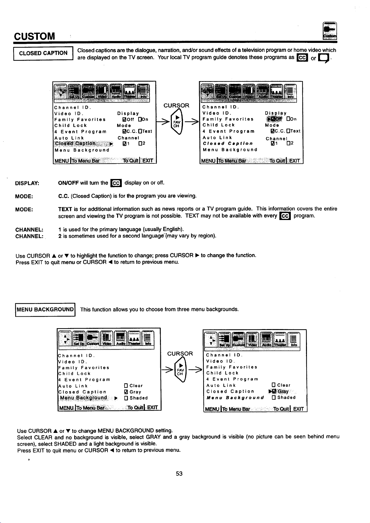
CUSTOM
CLOSED CAPTION
iFamily Favorites °lOft DOn
DISPLAY:
MODE:
MODE:
CHANNEL:
CHANNEL:.
I Closed captions are the dialogue, narration, and/or sound effects of a television program or home video which
are displayed on the TV screen. Your local TV program guide denotes these programs as r_ or I_-
mullmm
CURSOR
'° oisp,o,
Child Lock Mode
4 Event Program I_C.C.nText
Auto Link Channel
Menu Background
MENUIT0'MeriUi_ar _':_ !T6!Q_I:' _IT
ON/OFF will turn the r_ display on or off.
C.C. (Closed Caption) is forthe program you are viewing.
TEXT is for additional information such as news reports or a TV program guide. This informationcovers the entire
screen
and viewing the TV program is not possible. TEXT may not be available with every r_
1 is used for the primary language (usually English).
2 is sometimes used for a second language_{mayvary by region).
Channel ID.
Video ID. Disl_.! a y
Family Favorites non
Child Lock Mode
4 Event Program I_lc.c.r'lText
Auto Link Channel
Closed Caption _1 _2
Menu Background
program.
Use CURSOR • or • to highlightthe function to change; press CURSOR • to change the function.
Press EXIT to quit menu or CURSOR • to returnto previous menu.
MENU BACKGROUND I This function allows you to choose from three menu backgrounds.
" I
hannel IO. CURSOR Channel IO.
ideo ID. Video ID.
amily Favorites Family Favorites
;hild Lock Child Lock
Event Program 4 Event Program
,uto Link r'lclear Auto Link r'lClear
Closed Caption I_Gray Closed Caption
n Shaded Menu Background rl Shaded
MENUlTo_ _ ..... ToQuit MENU IToMenuBar; To _ltl EXIT
Use CURSOR • or • to change MENU BACKGROUND setting.
Select CLEAR and no background is visible, select GRAY and a gray background is visible (no picture can be seen behind menu
screen), select SHADED and a light background is visible.
Press EXIT to quit menu or CURSOR • to return to previous menu.
53
Page 54

Select VIDEO to adjust picture settingsand improve picture quality.
CURSOR
VIDEO
Contrast • d_
Br'ig'htness
ColOr ==,
Y
CURSOR
L •
Use the CURSOR • or • buttons to highlightthe functionto be adjusted.
Press the CURSOR < or • buttonsto adjust the function.
To set COLOR TEMP, highlight the function and then use CURSOR • or • to select and CURSOR • to set.
Use the CURSOR • or • buttons to highlight RESET or COLOR TEMP, then the CURSOR <1to return to previous menu.
Press EXIT to quitmenu.
NOTE: If CONTRAST is selected, you are adjusting CONTRAST. The additional menu items BRIGHTNESS, COLOR, TINT,
and SHARPNESS can be selected and adjusted in the same manner.
I CONTRAST
Tiht _ ,, ,, D
Sharpness ,<
Color [] Warm
Temp [] Cool
Reset []
MENUIToMenu Bar
Use this function to change the contrast between black and white levels in the picture.
To QuitI EXIT
CURSOR
Contrast i1_
Brightness _p
Color < ==,
Tint 4, ,, ,, ,,P
Sharpness _p
Color [3 Warm
Temp [] Cool
Reset []
MENU ITo Menu Bar To QuitI EXIT
BRIGHTNESS
I
I
I
1COLOR TEMPERA'rUREI
COLOR
TINT
SHARPNESS I
RESET
Use this function to adjustoverall picturebrightness.
I Use thisfunction to adjust the level of colorin the picture.
I Use this functionto adjust flesh tones so they appear natural.
Use this function to adjustthe amount offine detail in the picture.
Set this to WARM for hotter colorwith more red, or set to COOL for less intense colors with more blue.
When RESET isselected, press CURSOR • to return video adjustments to factory preset conditions.
54
Page 55

AUDIO
Select AUDIO to adjust the TV to your preference and to improve the sound quality.
CURSOR
Y
CURSOR
%.
Treble
Balance _ am Ip.
Reset r'l
Advanced
Settings
Volume
Correction
MENU ITo Menu Bar, ToQuitlEXIT
Bass I_i..._:__..11 i),
Treble < IP"
Balance q= IIII IIIb
Reset I"1
Advanced
Settings
Volume
Correction
I
CURSOR
J
CURSOR
I- >
Bass I _ ...... Ib"
Treble •
Balance _ mm lib"
Reset []
Advanced
Settings
Volume
Correction
J
MENUIToMenuBar...... To;Q,.,_tl_n"
Use CURSOR • or • to highlight the function to be adjusted.
Press CURSOR • or • to adjust the function.
Use CURSOR • or • to highlight RESET, ADVANCED SETTINGS, or VOLUME CORRECTION then CURSOR • to returnto previous
menu.
Press EXIT to quit menu.
NOTE:
If BASS is selected you are adjusting BASS. The additional menu items TREBLE and BALANCE can be selected and
adjusted in the same manner.
BASS
TREBLE
BALANCE
RESET
This function controls the low frequency audio to all speakers.
I
This function controls the high frequency audio to all speakers.
I
This function will control the leftto right balance of the TV internal speakers, the AUDIO TO HI FI output.
When RESET isselected, press CURSOR • to return audio adjustments to factory preset conditions.
I
MENUIToMenu Bar
To Quit I EXIT
[
55
Page 56

J ADVANCED
SETTINGS
......... AUDIO
Use ADVANCED SETTINGS to improve the sound performance of your TV depending on listeningconditions.
I
CURSOR
I_gl Sfereo
I-] Mono
N Second Audio Program
On Off
[] [] Internal Speakers
[] [] Auto Noise Cancel
[] [] Loudness
•._ [] Dynamic Bass
Bass
Treble
Balance
Reset
Volume
Correction
•t
[3
Advanced Settings
CURSOR
A
On Off
*_ [] Dynamic Bass
CURSOR
[] Stereo
[] Mono
[] Second Audio Program
[] I_ Auto Noise Cancel
[] I_ Loudness
AENUIToMenu Bar:
Press CURSOR • or • to highlighta function.
Press CURSOR • to change the function setting.
Press EXIT to quit menu or CURSOR • to retum to previous menu.
MTS MODE
Multi-Channel Television Sound will allow you to select STEREO (a stereo broadcast), SAP (second audio program) which may be a
secondary language, weather report, etc. or MONO (monaural sound) used when receiving a weak stereo broadcast.
The sources received will be displayed below the channel number. The source you select will be displayed to the left of the channel
number.See example below for each selection when both stereo and second audio are received (monaural is always received).
STEREOSELECTED SAPSELECTED MONO SELECTED
INT. SPEAKERS
This function is useful when firstsetting up the external speakers, or if you prefer to use only speakers from a separate stereo system.
AUTO NOISE CANCEL
This function eliminates the noise between stations.If a channel is tuned and is noisy,thisfunction will automatically eliminate the audio
for that channel.
LOUDNESS
This function will improve the quality of both low and highfrequency sounds when listening at low volume levels.
DYNAMIC BASS (36UX58B ONLY)
This function allows you to enjoy spectacular bass sound that would normally be heard only with expensive home speaker systems.
* NOTE: Dynamic Bass is only available for model 36UX58B.
I' I
56
Page 57
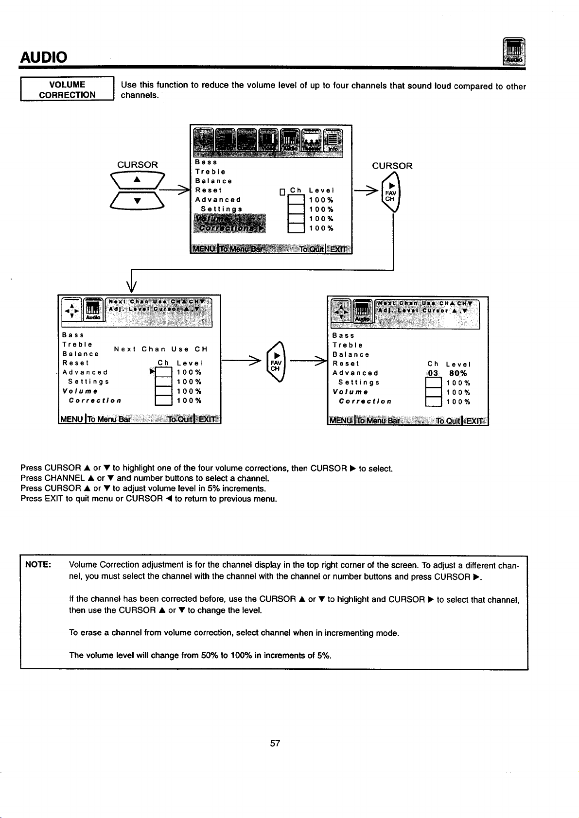
AUDIO
J VOLUME
CORRECTION
Bass
Treble
Balance
Reset Ch Level
Settings 100%
Volume 100%
Advanced _ 100%
Correction 100%
J se this function to reduce the volume level of up to four channels that sound loud compared to other
channels.
!!i
CURSOR
Next Chan Use CH
Bass
Treble
Balance
Reset
Advanced
Settings
100%
100%
I-]_ Level
100%
100%
f
Bass
Treble
Balance
Reset
Advanced
Settings
Volume
Correction
CURSOR
03
Ch
Level
80%
100%
100%
100%
MENUITo
Press CURSOR • or • to highlightone ofthe four volume corrections,then CURSOR I_ to select.
Press CHANNEL • or • and number buttons to select a channel.
Press CURSOR • or • to adjust volume level in 5% increments.
Press EXIT to quit menu or CURSOR • to return to previous menu.
NOTE:
Volume Correction adjustment is for the channel display in the top right corner of the screen. To adjust a different chan-
nel, you must select the channel with the channel with the channel or number buttons and press CURSOR •.
If the channel has been corrected before, use the CURSOR • or • to highlight and CURSOR • to select that channel,
then use the CURSOR • or • to change the level.
To erase a channel from volume correction, select channel when in incrementing mode.
The volume level will change from 50% to 100% in increments of 5%.
57
Page 58

THEATER
Use this function to choose Sound settingsfor a true THEATER experience.
Based on the principlesof the human hearing system, SRS technology delivers an exciting and realistic 3D
ISRS ( $ )'1
I NOTE: SRS ( • _ function is available for 36UX58B only. I
Sound experience from just two speakers (or) the two internal speakers of your HITACHI television. If your
HITACHI television is connected to an extemal audio system, SRS will also create an incredible 3D sound
experience from two speakers and even enhance a complete multi-speaker surround sound system.
CURSOR
SRS
Y
CURSOR
I-Ion
ME_ITo _
non
CURSOR
Off
CURSOR
SRS
Use CURSOR • or • to set SRS off or on.
Press exit to quit menu or CURSOR <1to return to previous menu.
NOTE:
SRS0the SRS symbol and Sound Retrieval System are registered trademarks of SRS Labs, Inc. in the U.S. and selected
countries. SRS Technology is manufactured under license from SRS Labs, Inc. and is protected by USA patents
4,748,669 and 4,841,572 and additional patents worldwide.
58
Page 59

THEATER
SURROUND
I The following surround settings will reproduce the "live" sound you would hear in concert halls, sport
stadiums, movie theaters, etc. when you set up your speaker system as shown in the section on rear panel
connections on page 20. The surroundsystem ismost effective with movie and other stereo material that is
Dolby Surround encoded, and played on a stereo VCR.
Surround sound allows the viewer to enjoy sound which provides a feeling of =presence" from stereo
broadcasts and VCR tapes recorded with stereo sound. Also at mono input, simulating a stereo will increase
the sound giving the listenersimulated surround sound.
CURSOR
Y
CURSOR
Surround :1_ I_ Off
n Music
[] Movies
[] Simulate
CURSOR
MENUITo Toou l,EXIT
•Surround b,_l Off
MENU ITo Menu Bar To,QuklEXI_
Press CURSOR • or • to highlight a surround function.
Press CURSOR I_ to change the surround function.
Press exit to quit or CURSOR ,< to return to previous menu.
SURROUND OFF
Use this for normal stereo/mono broadcasts.
NOTE: If sound is noisy when a stereo broadcast is received, and the TV is setto the SURROUND mode, decrease the TREBLE I
controlor turn the Surround OFF.
MOVIE SURROUND
Listener is surrounded by many sound sources such as a movie theater reproduction.
I NOTE: Some TV systems do not transmitoptimum audio channel separation which can reduce the effectiveness of the MOVIE
MUSIC SURROUND
Resonant Sound-Listener has the feeling ofbeing in a concert hall. At stereo input, the sound of music increases.
SURROUND function.
[] Music
[] Movies
[] Simulate
CURSOR
Surround [] Off
_l_l Music
n Movies
[] Simulate
MENU IToMenu Bar To QuitI EXIT
I
SIMULATE SURROUND
At mono input, sound is increased, simulating a stereo like Surround.
Your VCR must be a Hi-Fi or stereo unit. See page 19 for stereo VCR connection. Set must be outputtingstereo. (See MTS Mode:
Stereo on page 56).
I NdTE: Surround functions are not available for model 36UX58B. I
59
Page 60

This function allows your TV to assist you with your busy day-to-day schedule.
INFO
I SPECIALEVENT
REMINDER
CURSOR
I se this function to set up to six special events into memory,
These events can then be viewed in CALENDAR mode.
CURSOR
Calendar
.-->
Special Event Reminder
02 03 1_4 05 06
Set Special Day JAN 01
Start Reminder
I-IOn Special Day
I"1 1 Day before
[] 1 Week before
I01Off
Press CURSOR b. to select EVENT 1 to 6.
Press CURSOR • to select remainder message.
Press CURSOR • or • to select a letter.
Press CURSOR • or • to change position.
Highligl_t the day of first reminder using CURSOR buttons, then press CURSOR • to select.
Select date of reminder using CURSOR buttons.
To erase SPECIAL EVENT, select ERASE EVENT then press CURSOR •.
Press EXIT to quit menu or CURSOR • to return to previous menu, when the CURSOR is in the first position.
1997
ToQuitl_1_
I NOTE: andSpecialDay mode has a default date (for example, Jan 011997).thenext screen will appear. If the cl°ck is n°t set' you can n°t use this functi°n I
Calendar
Please Set
Clock First
NOTE:
Special events set into memory will appear as blinking cyan dates in CALENDAR mode. At the selected time, the mes-
sage will appear in CALENDAR mode.
When the TV is turned on, the SPECIAL EVENT REMINDER message will automatically appear at the selected time.
Each special event message can be a maximum of 20 characters.
6O
Page 61

INFO
I CALENDAR
I se this function to check the day, month, and year.
Dates programmed in SPECIAL EVENT REMINDER will appear blinking and special event message will
be displayed.
CURSOR
Calendar
_ENUl_dM Exrr
Press CURSOR • or • to change the month.
Press EXIT to quitmenu or CURSOR .4 to return to previous menu.
If the clock is not set, you can not use this function and the next screen will appear.
• w F S
,JAN 1997
1 2 3 4
5 6 7 8 9 10 11
12 13 14 15 16 17 18
19 20 21 22 23 24 25
26 27 28 29 3O 31
NOTE:
Special
Event Reminder
C_ai_nd er _*
Please Set
Clock First
I:MENUIToMen_: : i:_o'Quitl_lT;
Dates ofSPECIAL EVENT REMINDER willappear blinking. Special event message willbe displayed onlyif currentdate
is within the Day Of First Reminder Specifications as chosen in SPECIAL EVENT REMINDER. (See page 60.)
CALENDAR will appear blinking when Special Event message is set.
61
Page 62

CARE OF YOUR HITACHI COLOR TV
AND YOUR REMOTE CONTROL
DO
Make sure the TV set is turned OFF when cleaning the screen.
Dust the screen and cabinet with a soft cloth.
Clean the screen with a soft cloth moistened in warm water and dry with a soft cloth. A mild soap may be used if
the screen is extremely dirty.
Place your television away from extreme heat, humidity,and extremely dusty places.
Remove the plug from the wall outlet if your television will not be used for a long period of time, for instances,
when you go on vacation.
DO NOT
Do not clean your screen or cabinet with strongcleaners, polishes or a chemically treated cloth.
Do not place rubber or vinyl products or cellophane tape on your television.
Do not touch the screen too often.
Do not subject the remote control to shocks such as dropping it on the floor, etc. Physical damage to the precision
parts may result.
Avoid placing the remote control in a high humidity place or getting it wet. Do not leave it on or near a heater.
Excessive heat or moisture may cause the unit to cease operation.
When the batteries run down, remote control operation will become erratic or possibly stop altogether. Replace the
old batteries with two new "AA" size batteries.
62
Page 63

RECEPTION PROBLEMS
J
• IGNITION NOISE:
Black spots or horizontal streaks may appear, picture may flutter or drift.
Usually caused by interference from automobile ignition systems, neon
lamps, electrical drills, and other electrical appliances.
• GHOSTS:
Ghostsare caused by the television signal followingtwo paths. One isthe
directpath and the other is reflected from tall buildings,hillsor some other
objects. Changing the direction or position of the antenna may improve
reception. Ghosting may also be caused by defects in the antenna system
such as unshielded leads or connecting several sets to the same antenna
withoutusing multipleantenna couplers.
• SNOW:
If your receiver is located in the fringe area of a television station where
the signal isweak, your picture may be marred by the appearance of small
dots. When the signal is extremely weak, it may be necessary to installa
special antenna to improve the picture.
NOTE:
• RADIO FREQUENCY INTERFERENCE:
The interference produces moving ripples or diagonal streaks, and in
some cases, causes loss of contrast in the picture.
The TV set can generate sound distortionin external devices such as a radio.
Please separate radio equipment from the TV set to a considerable distance.
L
63
Page 64

SYMPTOMS
NoPicture, nosound • • • • • • •
Sound OK, picture poor • • • • • • • •
Picture OK, sound poor • • • •!• • •
Picture blurred • • •! •1 • •
Lines or streaks in picture • • • • •
Poor reception on some channels • •! • •' •
USEFUL INFO
Picture rolls vertically • •
No color • • • • • •
Poor color • • • • • • •
HITACHI Color Television incorporates advanced power surge protection technology designed to protect against com-
ponent or circuit damage due to external or internal voltage power surges.
IF YOUR TELEVISION SHOULD APPEAR TO HAVE A LOSS OF POWER, PLEASE FOLLOW THIS PROCEDURE:
1. Press the power switch (ON/OFF switch) once.
2. If there is still no power, wait 30 seconds and press the power switch again.
3. If there is still no power, unplug the power cord from the wall. Wait 30 seconds and plug the power cord back in.
Press the power switch again.
This protective technology should provide for years of lasting entertainment from your HITACHI Color Television.
64
Page 65

USEFUL INFO
Features:
• ULTRA BLACK INVAR MASK (36UX58B only)
• Superfine Picture Quality
700 Line Horizontal Resolution
• Ultra Black CRT (32FX48B only)
• Remote Transmitter
(Controlsmany VCR, cable box, and satellite brands.)
• P-in-P Functions
• ULTRATEC BIT-MAP OSD
• Full set of input jacks, including S-Video
• Closed Caption Decoder
• Comb Filter, Wide-Band Video-Amp and Color Temperature Control
• MTS (Multi-Channel Television Sound) Stereo Broadcast Reception
• 3D Surround Sound (3 way) (36FX48B, 32FX48B)
• VM-Velocity Modulation (36UX58B only)
• sRsCQ_ (36UX58B only)
• Improved AUTO LINK
• Dynamic Bass (36UX58B only)
Screen Size:
Inputs:
• Power Input .................. AC 120V, 60Hz
Power Consum_ion (operating)
32FX48B ........................... 132W
36UX58B. .......................... 145W
36FX48B ........................... 143W
Power Consumption(maximum)
32FX48B ........................... 176W
36UX58B ........................... 193W
36FX48B ........................... 190W
Antenna input impedance ............. 75 Ohm
Channel coverage ................... 181 ch.
VHF-Band .......................... 2 ~ 13
UHF-Band ......................... 14 ~ 69
CATV Mid Band ................... A-5 - A-1
Super Band ........................... J-W
Hyper Band .................... W+I - W+28
Ultra Band .................... W+29 - W+84
• Video ..................... 1.0Vp-p, 75 Ohm
• S-Video
Luminance (Y) ............... 1.0Vp-p, 75 Ohm
Chrominance (C) ........... 0.286V.p-p, 75 Ohm
32V (32 inches measured diagonally) 32FX48B.
36V (36 inches measured diagonally) 36UX58B and 36FX48B.
................................ A-1
Outputs:
• Video
• Audio
(36UX58B only)
..................... 1.0Vp-p. 75 Ohm
................... 470mVrms, lk Ohm
Dimensions:
32FX48B 36UX58B
36FX48B
• Height (in.) 26 5/16 29 17/32
• Width (in.) 31 1/16 35
• Depth (in.) 22 1/4 24 13/32
• Weight (Ibs.) 120 176
Due to improvements, specifications in this oper- I
I NOTE:
ating guide are subject to change without notice.
I
[
• Audio inputlevel ................... 47k Ohm
• Average inputlevel ................ 470mVrms
• Maximum input level ............... 940mVrms
65
Page 66

HITACHI
USEFUL INFO
To locate an authorized
HITACHI service facility
in the continental U.S.A.
and Canada,
DIAL TOLL FREE
7 days a week, 24 hours a day
(1-800-448-2244)
Hitachi Home Electronics (America), Inc.
Hitachi has made every effort to assure you hours of trouble free operation from your unit. However, should you require service,
a network of Hitachi Authorized Service Facilities has been established in all 50 states and Puerto Rico. Each facility will provide
you with convenient and expedient assistance. Our service hotline operator will direct you to the Hitachi Authorized Service
Facility nearest you. Just present proof of purchase and/or delivery receipts to the Hitachi Authorized Service Facility, and ser-
vice will be rendered in accordance with the terms of the limited warranty as stated on your warranty card or operating guide.
Should you have any questions regarding warranty, service, operation, or technical assistance, please contact:
Hitachi Home Electronics (America), Inc.
3890 Steve Reynolds Bivd,
Norcross0GA 30093
Tel: 770-279-5600
i
For TVs purchased in Canada only. please contact one of the Hitachi offices below, should you have any ques-
tions regarding service, operation, or technical assistance.
MONTREAL
9425 Trans Canada
Saint-Laurent, Quebec
H4S 1V3
Tel: (514) 956-9882
Fax: (514) 956-9761
TORONTO
6740 Campobelio Road
Mississauga, Ontario
L5N 2L8
Tel: (905) 821-4545
Fax: (905) 826-6627
Hitachi Sales Corporation of Hawaii
3219 Koapaka St.
Honolulu, HI 96819
Tel: 808-839-3621
VANCOUVER
20800 Westminster Hwy., Unit 1103
Richmond, B.C.
V6V 2W3
Tel: (604) 214-0777
Fax: (604) 214-0772
66
Page 67

NOTES
67
Page 68

HITACHI
QR25372
 Loading...