

Page 1
SOLID STATE COLOR TV
OPERATING GUIDE
(_ __
_ ,_/_
I'"_
IP:----_,__1_ AsK
IMPORTANT SAFEGUARDS
FIRST TIME USE
THE REMOTE CONTROL
COLOR GRAPHIC GUIDE
USEFUL INFORMATION
INDEX
2-5
6-19
20-31
3;_.-49
50-55
Page 2
/k
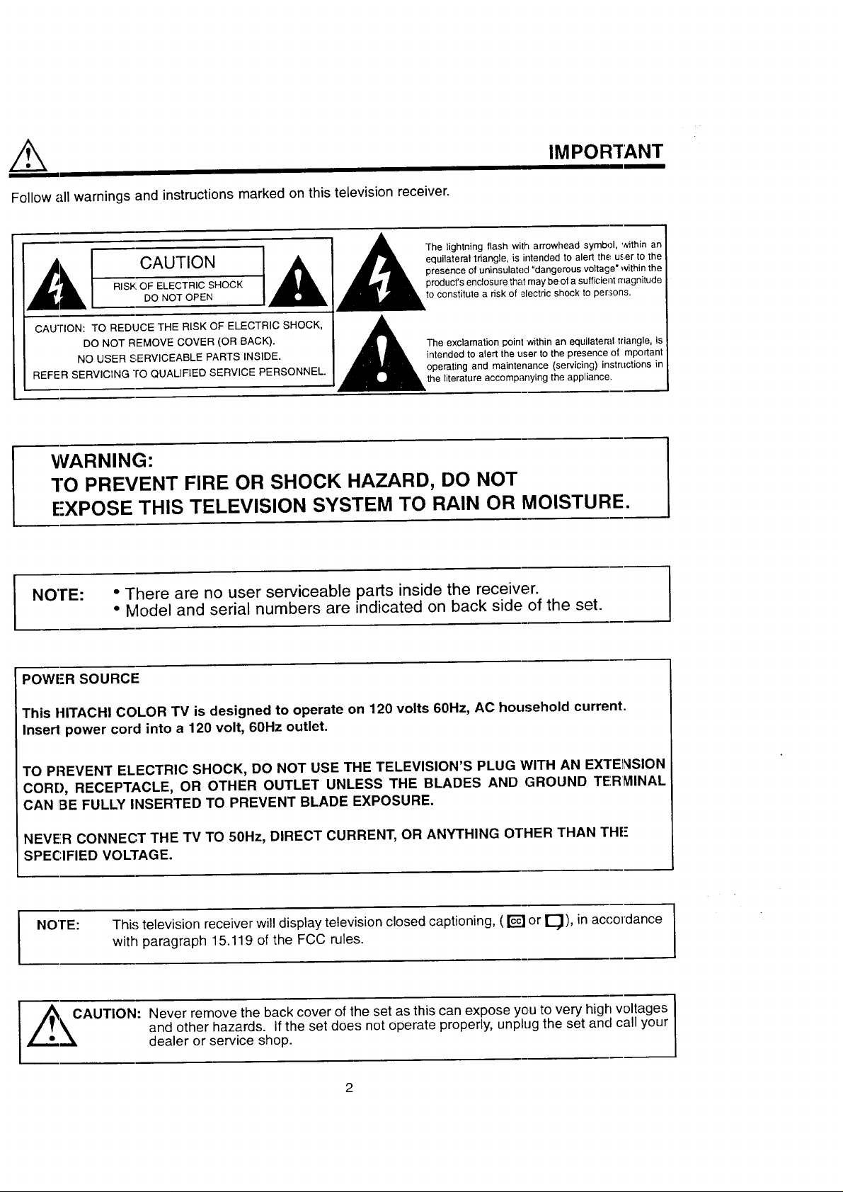
Follow all warnings and instructions marked on this television receiver.
IMPORTANT
CAUTION equilateral triangle, is intended to alert the user to the
RISK OF ELECTRIC SHOCK product's enclosure that may be of a sufficient magnitude
DO NOT OPEN J,__/,_1_i= to constitute a risk of _,ectdc shock to per:,ons.
CAUTION: TO REDUCE THE RISK OF ELECTRIC SHOCK, _ ,_
NO USER SERVICEABLE PARTS INSIDE. intended to alert the user to the presence of mportant
REFER SERVICrNG ro QUALIFIED SERVICE PERSONNEL. operating and maintenance (servicing) instructions in
DO NOT REMOVE COVER (OR BACK). [_The exclamation point within an equilateral triangle, is
1 1A The'i htn'°o"ashw"harr°w"eaO' "hinen
presence of uninsulated "dangerous vo{tage* within the
the literature accompanying the appliance.
WARNING:
"!"OPREVENT FIRE OR SHOCK HAZARD, DO NOT
E'XPOSE THIS TELEVISION SYSTEM TO RAIN OR MOISTURE.
NO'rE: ° There are no user serviceable parts inside the receiver.
• Model and serial numbers are indicated on back side of the set.
POWER SOURCE
This HITACHI COLOR TV is designed to operate on 120 volts 60Hz, AC household current.
Insert power cord into a 120 volt, 60Hz outlet.
TO PREVENT ELECTRIC SHOCK, DO NOT USE THE TELEVISION'S PLUG WITH AN EXTENSION
CORD, RECEPTACLE, OR OTHER OUTLET UNLESS THE BLADES AND GROUND TE'.R_IINAL
CAN 1BEFULLY INSERTED TO PREVENT BLADE EXPOSURE.
NEVER CONNECT THE TV TO 50Hz, DIRECT CURRENT, OR ANYTHING OTHER THAN THE"
SPECIFIED VOLTAGE.
NOTE: This television receiver will display television closed captioning, ( _] or _), in accordance
with paragraph 15.119 of the FCC rules.
Zi_= __CAUTION: Never remove the back cover of the set as this can expose you to very high voltages
and other hazards, if the set does not operate properly, unplug the set and call your
dealer or service shop.
2
Page 3
IMPORTANT
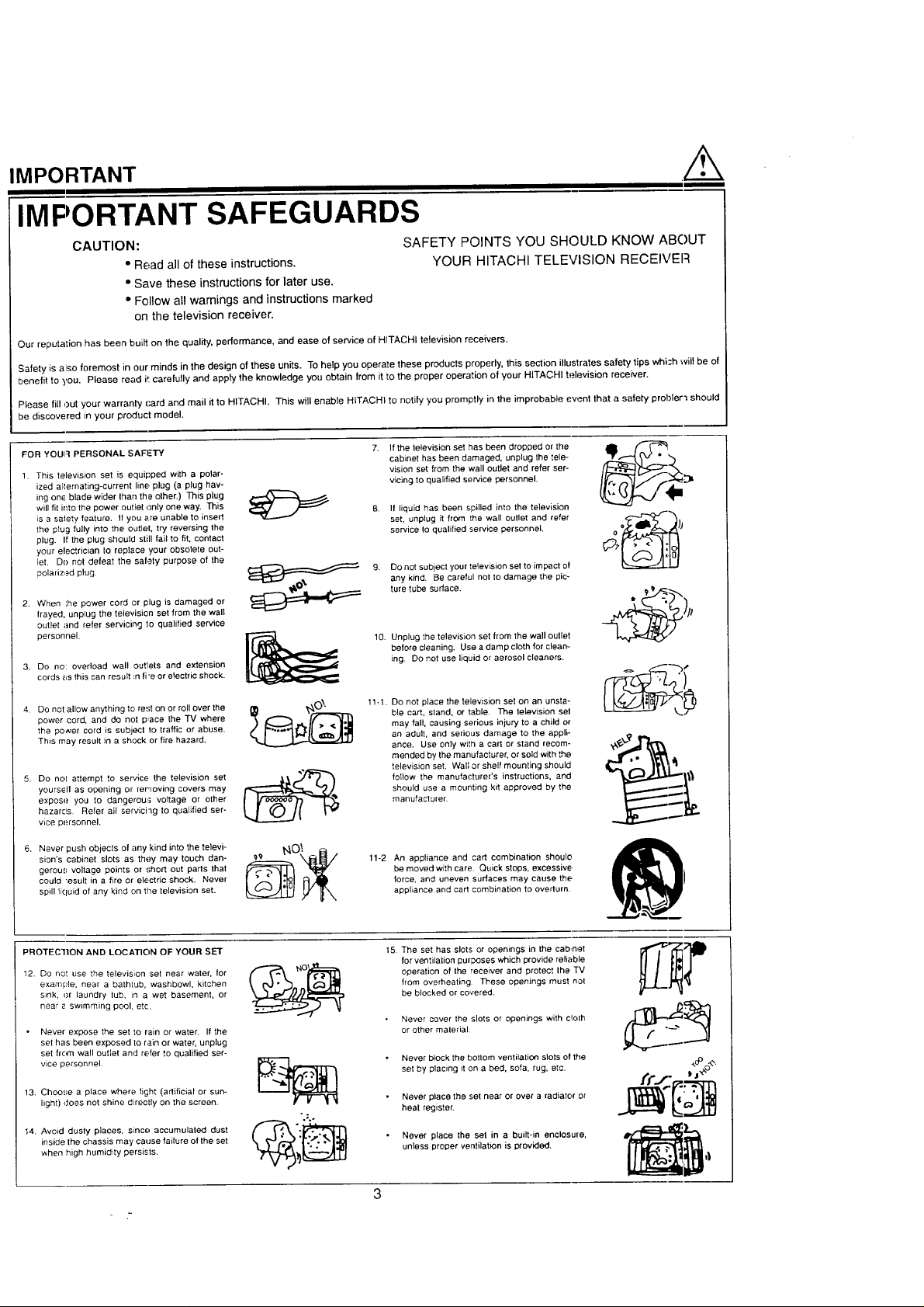
IMPORTANT SAFEGUARDS
CAUTION:
• Read all of these instructions.
SAFETY POINTS YOU SHOULD KNOW ABOUT
YOUR HITACHI TELEVISION RECEIVEFI
• Save these instructions for later use.
° Follow all wamings and instructions marked
on the television receiver.
Our reputation has been built on fhe quality, performance, and ease of service of HITACHI television receivers.
Safety is also foremost in our minds in the design of these units. To help you operate these products properly, this section illustrates safety tips whish will be of
benefit to you. Please read it carefully and apply the knowledge you obtain from it to the proper operation of your HITACHI television receiver.
Please fill out your warranty card and mail it to HITACHI. This will enable HITACHI to notify you promptly in the improbable event that a safety probler'_ should
be discovered in your product model.
FOR YOUI:_ PERSONAL SAFETY
1. This television set is equipped with a polar-
ized alternating-current line plug (a ptug hav-
ing one blade wider than the other.) This plug
will fit into the power outlet c,nly one way. This
is a satety fealure. I1you are unable to insert
the plug fully into the outlet, try reversing the
plug. If the plug should still fail to fit, contact
your electrician to replace your obsolete out-
let. Do not defeat the safety purpose of the
polarized plug.
2. When ',he power cord or plug is damaged or
flayed, unplug the television set from the wall
outlet and refer servicing to qualified service
personnel.
3. DO no: overload wall outlets and extension
cords as this can result n fi'e or electric shock.
If fhe television set has been dropped or the
cabinet has been damaged, unplug the tele-
vision set from the wall outlet and refer ser-
vicing to qualified service personnel.
If liquid has been spilled into the television
set, unplug it from the wall outlet and refer
service to qualified service personnel.
9.
Do not subject your television set to impact of
any kind. Be careful nol to damage the pic-
ture tube surface.
10.
Unplug the television set from the wall outlet
before cleaning. Use a damp cloth for clean-
ing. Do not use liquid or aerosol cleaners.
4. Do not allow anything to rest on or roll over the
power cord, and do not p,ace the TV where
the power cord is subject to traffic or abuse.
This may result in a shock or fire hazard.
5. Do nol attempt to service the television set
yourself as opening or removing covers may
expose you to dangerous voltage or other
hazards Refer oil servichg to qualified ser-
wce personnel.
6. Never push objects of any kind into the tetevi-
sion's cabinet slots as they may touch dan-
gereus voltage points or short out parts that
could "esult in a fire or electric shock. Never
spill licluid of any kind on the television set.
PROTECTION AND LOCATION OF YOUR SET
12. Do not use the television set near water, for
example, near a bathtub, washbowl, kitchen
sink, or laundry tub, in a wet basement, or
near e swimming pool, etc.
Never expose the set to rain or water. If the
set has been exposed to rain or water, unplug
set lrom wall outlet and refer to qualified ser-
vice personnel.
13. Choose a place where fi§ht (artificial or sun-
light) does not shine directly on the screen.
14. Avoid dusty p]aces, s_nce accumulated dust
inside Ihe chassis may cause failure of the set
when high humidity persists.
°o;O
11-1.
Do not place the television set on an unsta-
ble cart, sland, or table. The television set
may fall, causing serious injury to a child o_"
an adult, and serious damage to the appli-
ance. Use only with a cart or stand recom-
mended by the manufacturer, or sold with the
television set. Wall or shelf mounting should
foIIow the manufacturer's instructions, and
should use a mounting kit approved by the
manufacturer.
11-2 An appliance and cart combination shoule
be moved with care. Quick stops, excessive,
force, and uneven surfaces may cause the
aopliance and cart combination to ovelturn.
15.
The set has slots or openings in the cabnet
for ventilation purposes which provide reliable
operation of the receiver and protect the TV
from overheating These openings must not
be blocked or covered.
• Never cover the slots or openings with cIoIh
or other malerial
• Never block the bottom ventilation slots of the
set by placing it on a bed, sofa, rug, etc.
• Never place the set near or over a radiator or
heat register.
• Never place the set in a built-in enclosure,
unless proper ventilation is provided.
3
Page 4
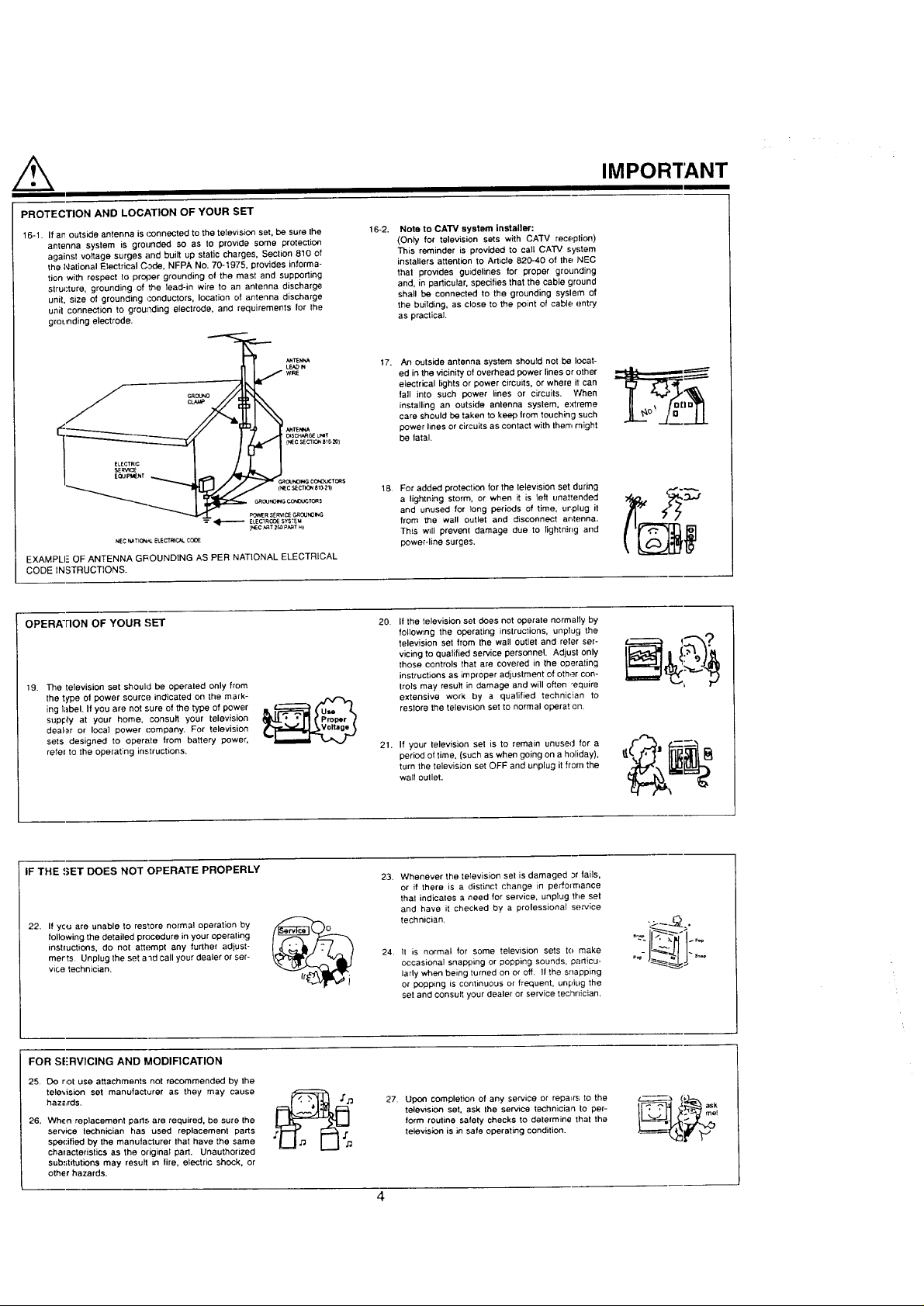
PROTECTION AND LOCATION OF YOUR SET
16-1. If an outside antenna is connected to the television set, be sure the
antenna system is grounded so as to provide some protection
against voltage surges and built up static charges, Seclion 810 of
the National Electrical Code. NFPA No. 70-1975, provides informa-
tion with respect to proper grounding of the mast and supporting
structure, grounding of the lead-in wire to an antenna discharge
unit, size of grounding _:onduotors, location of antenna discharge
unit connection to grounding electrode, and requirements for the
grounding electrode.
E LECTR_C (i_ 1 7c sECTI_ BI0-_)
SERVlC_
_ ELECIRO_ESYSTEU
NEC_TK_ ELECTFeC_COOE
EXAMPLE OF ANTENNA GROUNDING AS PER NATIONAL ELECTRICAL
CODE INSTRUCTIONS.
NO_IGCCNOL_TORS
GROUNO_GCONOUCTORS
_R SER_ GR0UN0=NG
{NEC_t z_P_T_)
16-2. Note to CATV system installer:
(Only for television sets with CA'TV reception)
This reminder is provided to call CAW system
installers attention to Article 820-40 of the NEC
that provides guidelines for proper grounding
and, in particular, specifies that the cable ground
shall be connected to the grounding syslern of
the building, as close to the point of cable entry
as practical.
17. An outside antenna system should not be locat-
ed in the vicinity of overhead power lines or other
electrical lights or power circuits, or where il can
tall into such power lines or circuits. When
installing an outside antenna system, e:dreme
care should be taken tO keep from touching such
power lines or circuits as contact with then, might
be latal.
18. For added protection for the television set during
a lightning storm, or when it is left unattended
and unused for long periods of time, urplug it
from the wall outlet and disconnect arltenna.
This witl prevent damage due to tightnirlg and
power-line surges.
IMPORTANT
OPERA'FION OF YOUR SET 20.
tg. The television set should be operated only from
the type of power source indicated on the mark-
ing label. If you are not sure of the type of power
supply at your home, consult your television
dealer or leca] power company. For television
sets designed to operate from battery power,
refel to the operating instructions.
IF THE !.;ET DOES NOT OPERATE PROPERLY
22. If you are unable to restore normal operation by
following the detailed procedure in your operating
instluctions, do not attempt any further adjust-
merts Unplug the set a"=d call your dealer or ser-
vice technician.
FOR S[;RVICING AND MODIFICATION
25. DO not use attachments not recommended by the
tele'_ision set manufacturer as they may cause
haz_LrdS.
26. When replacement parts are required, be sure the
service technician has used replacement parts
spe{:ified by the manulaclurer that have the same
chalacteristics as the original part. Unauthorized
substitutions may result in tire, electric shock, or
othe r hazards.
If the television set does not operate normally by
following the operating inslrections, unplug the
television set from the wall outlet end refer ser-
vicing to qualified service personnel. Adjust only
those controls that are covered in the operating
instructions as improper adjustment of other con-
trois may result in damage and will often "equire
extensive work by a qualified technician to
restore the television set to normal operat on.
21.
If your television set is to remain unused for a
period of time, (such as when going on a heliday),
turn the television set OFF and unplug it from the
wall oullet.
23. Whenever the television set is damaged Jr fails,
or if there is a distinct change in performance
thai indicates a need for service, unplug the set
and have it checked by a prolessional service
technician.
24. It is normal for some television sets to make
occasional snapping or popping sounds, parlieu-
lady when being turned on or off. If the snapping
or popp_ng is continuous or frequent, unplug the
set and consult your dealer or service technician.
27. Upon completion of any service or repairs to the
television set, ask the service technician to per-
form routine safely checks to determine that the
television is in safe operating condition.
"_-I&: :.-
..L?I....
ask
Page 5
PICTLIRE CAUTIONS
Continuous On-Screen Displays such as
video games, stock market quotations,
computer generated graphics, and other
fixed (non-moving) patterns can cause per-
manent damage to Color Television
WARNING
Receivers. Such "PATTERN BURNS" con-
stitute misuse and are NOT COVERED by
your HITACHI Factory Warranty.
When using the Picture-in-Picture function, the sub-picture should not be left permanently
in one corner of the screen or a "PATTERN BURN" may develop over a long period of time.
This color television receiver was intended mainly for the private viewing of programs
broadcast by TV stations, cable companies, and programs from other video sources.
Public viewing may require prior authorization from the broadcaster or owner of the video
program.
Page 6
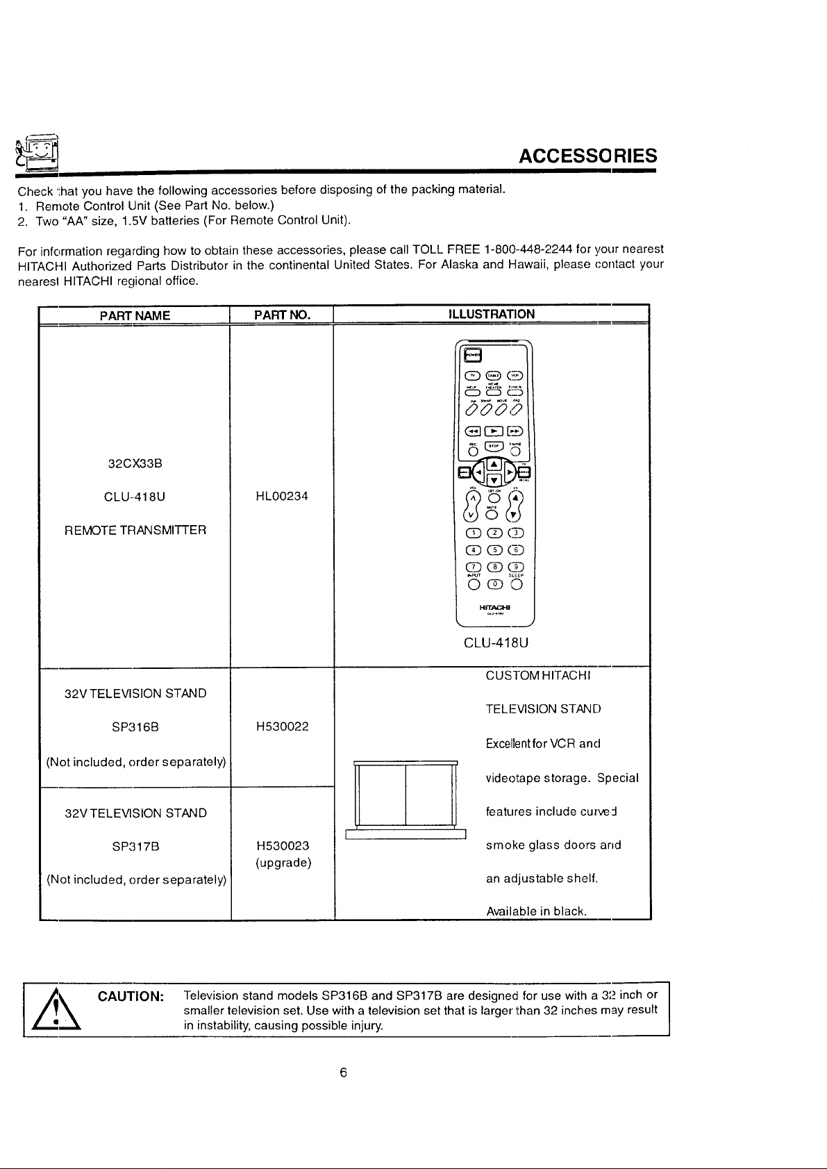
ACCESSORIES
Check !:hatyou have the following accessories before disposing of the packing material.
1. Remote Control Unit (See Part No. below.)
2. Two "AA" size, 1.5V batteries (For Remote Control Unit).
For infermation regarding how to obtain these accessories, please call TOLL FREE 1-800--448-2244 for your nearest
HITACHI Authorized Parts Distributor in the continental United States. For Alaska and Hawaii, please contact your
nearesl HITACHI regional office.
PART NAME 1 PART NO. I ILLUSTRATION
.... _ ......
CC) (Z3 C__
0000
OE] [__)
32CX33B
6
CLU-.418U
REMOTE TRANSMITTER
32V TELEVISION STAND
SP316B
(Not included, order separately)
32VTELEV1SION STAND
SP'317B
(Not included, order separately)
HL00234
H530022
H530023
(upgrade)
F ]
(]D (]D (]]
(£] (]] (£]
(]] (£] (]]
_p_ £&EEI
O@ 0
l-,lIT.,_I
CLU-418U
CUSTOM HITACHI
TELI--_VISIONSTAND
Excellentfor VCR and
videotape storage. Special
features include curve;I
smoke glass doors arid
an adjustable shelf.
CAUTION:
Available in black.
I
Television stand models SP316B and SP317B are designed for use with a 3L_inch or I
smaller television set. Use with a television set that is larger than 32 inches may result
in instability, causing possible injury.
Page 7
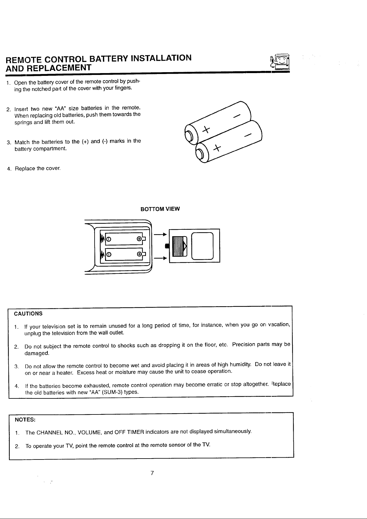
REMOTE CONTROL BATTERY INSTALLATION
AND REPLACEMENT
1. Open the battery cover of the remote control by push-
ing the notched part of the cover with your fingers.
Insert two new "AA" size batteries in the remote.
When replacing old batteries, push them towards the
springs and lift them out.
Match the batteries to the (+) and (-) marks in the
battery compartment.
Replace the cover.
BOTTOM VIEW
J
CAUTIONS
1. If your television set is to remain unused for a long period of time, for instance, when you go on vacation,
unplug the television from the wall outlet.
2. Do not subject the remote control to shocks such as dropping it on the floor, etc. Precision parts may be
damaged.
3. Do not allow the remote control to become wet and avoid placing it in areas of high humidity. Do not leave it
on or near a heater. Excess heat or moisture may cause the unit to cease operation.
4. If the batteries become exhausted, remote control operation may become erratic or stop altogether. Replace
the old batteries with new "AA" (SUM-3) types.
NO'fES:
1. ]-he CHANNEL NO., VOLUME, and OFF TIMER indicators are not displayed simultaneously.
2. To operate your TV, point the remote control at the remote sensor of the TV.
Page 8
HOW TO SET UP YOUR NEW HITACHI COLOR TV
ANTEN_IA
Unless your TV is connected to a cable TV system or to a centralized antenna system, a good outdoor color TV anten-
na is recommended for best performance. However, if you are located in an exceptionally good signal area that is free
from interference and multiple image ghosts, an indoor antenna may be sufficient.
LOCATION
Select an area where sunlight or bright indoor illuminationwill not fall directly on the picture screen. Also, be sure that
the location selected allows a free flow of air to and from the back cover of the set.
To avoid cabinet warping, cabinet color changes, and increased chance of set failure, do not place the TV where tem-
peratures can become excessively hot, for example, in direct sunlight or near a heating appliance, etc.
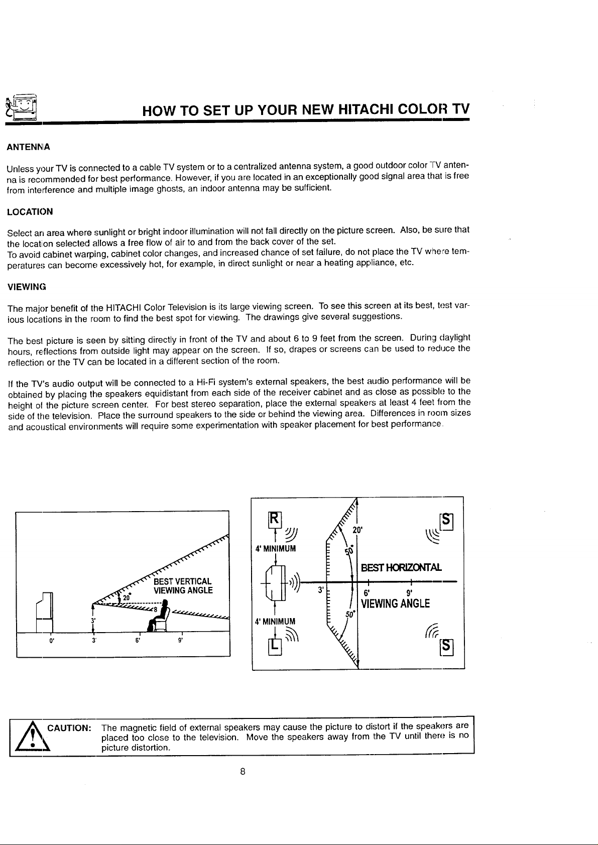
VIEWING
The major benefit of the HITACHI Color Television is its large viewing screen. To see this screen at its best, test var-
ious locations in the room to find the best spot for viewing. The drawings give several suggestions.
The best picture is seen by sitting directly in front of the TV and about 6 to 9 feet from the screen. During daylight
hours, reflections from outside light may appear on the screen. If so, drapes or screens can be used to reduce the
reflection or the TV can be located in a different section of the room.
If the TV's audio output will be connected to a Hi-Fi system's external speakers, the best audio performance will be
obtained by placing the speakers equidistant from each side of the receiver cabinet and as close as possible to the
height ol the picture screen center. For best stereo separation, place the external speakers at least 4 feet from the
side of the television. Place the surround speakers to the side or behind the viewing area. Differences in room sizes
and acoustical environments will require some experimentation with speaker placement for best performance
O' 3' 6'
The magnetic field of external speakers may cause the picture to distort if the speakers are
placed too close to the television. Move the speakers away from the TV until there is no
picture distortion.
VIEWINGANGLE
I
91
Page 9
HOOKUP CABLES AND CONNECTOR
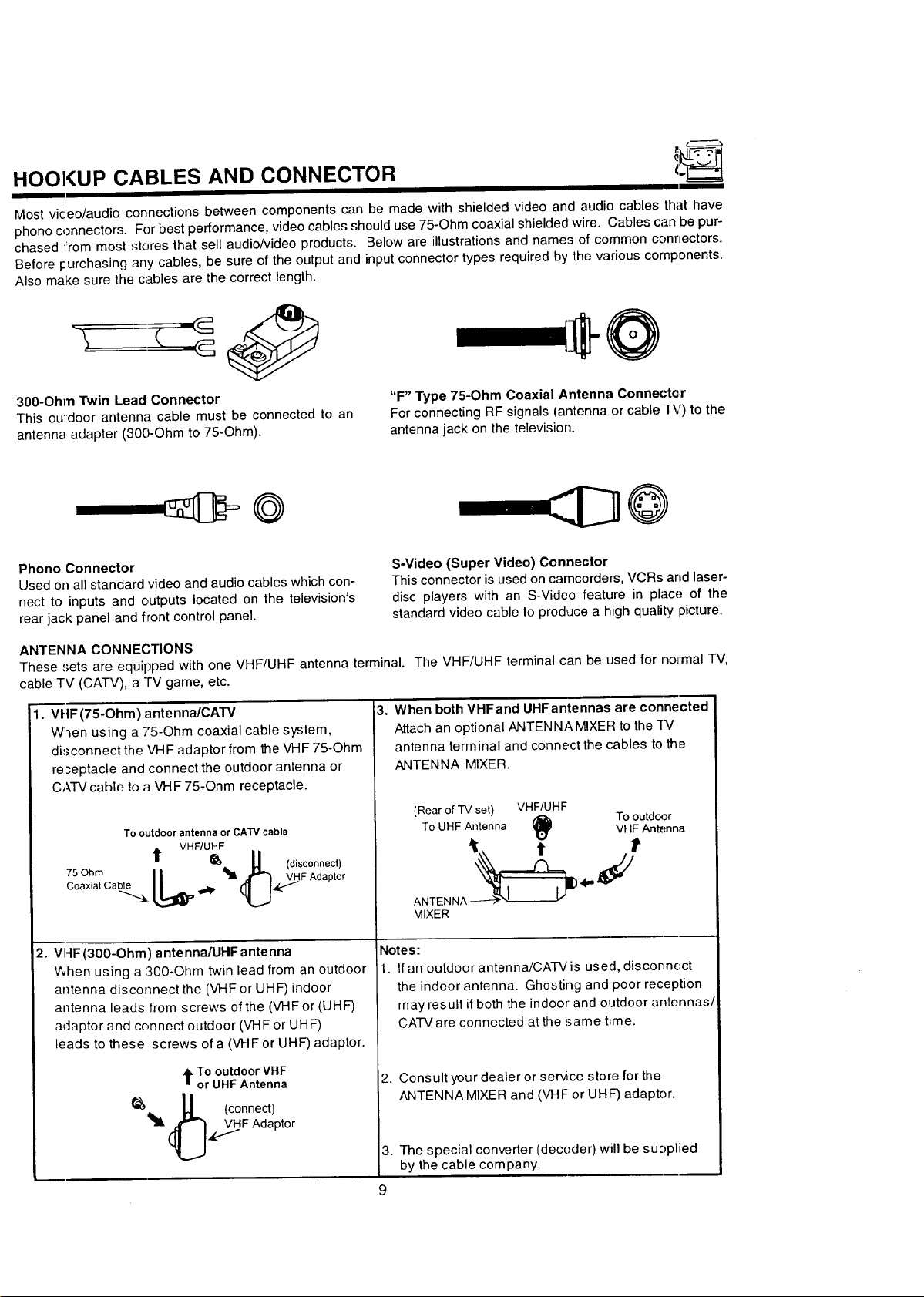
Most video/audio connections between components can be made with shielded video and audio cables that have
phono connectors. For best performance, video cables should use 75-Ohm coaxial shielded wire. Cables can be pur-
chased From most stores that sell audio/video products. Below are illustrations and names of common connectors.
Before purchasing any cables, be sure of the output and inputconnector types required by the various components.
Also make sure the cables are the correct length.
@
300-Ohm Twin Lead Connector
This ouIdoor antenna cable must be connected to an
antenna adapter (300-Ohm to 75-Ohm).
Phono Connector
Used on all standard video and audio cables which con-
nect to inputs and outputs located on the television's
rear jack panel and front control panel.
ANTEN NA CONNECTIONS
These 'Jets are equipped with one VHF/UHF antenna terminal. The VHF/UHF terminal can be used for normal "IV,
cable TV (CATV), a TV game, etc.
1. VHF(75-Ohm) antenna/CATV
When using a 75-Ohm coaxial cable system,
disconnect the VHF adaptor from the VHF 75-Ohm
re;eptacle and connect the outdoor antenna or
CATVcable to a VHF 75-Ohm receptacle.
To outdoor antenna or CATV cable
t VHF/UHF
75 Ohm
Coaxial Cable
.. _'__,. U (disconnect)
|| _ VHFAdaptor
"F" Type 75-Ohm Coaxial Antenna Connector
For connecting RF signals (antenna or cable TV) to the
antenna jack on the television.
S-Video (Super Video) Connector
This connector is used on camcorders, VCRs and laser-
disc players with an S-Video feature in place of the
standard video cable to produce a high quality ;)icture.
3. When both VHFand UHFantennas are connected
Attach an optional ANTENNA MIXER to the "fV
antenna terminal and connect the cables to the
ANTENNA MIXER.
(Rear of TV set) VHF/UHF
To UHF Antenna VHF Antenna
ANTENNA _ 4"" J
MIXER
To outdoor
2. VII-IF(300-Ohm) antennaA.IHF antenna
When using a 300-Ohm twin lead from an outdoor
antenna disconnect the (VHF or UHF)indoor
antenna leads from screws of the (VHF or (UHF)
adaptor and connect outdoor (VHF or UHF)
leads to these screws of a (VHF or UHF) adaptor.
,IFTo outdoor VHF
or UHF Antenna
(connect)
[_F Adaptor
Note s:
• If an outdoor antenna/CATV is used, discornect
the indoor antenna. Ghosting and poor reception
may result ifboth the indoor and outdoor antennas/
CATV are connected at the same time.
Consult your dealer or ser_ce store for the
ANTENNA MIXER and (VHF or UHF) adaptor.
3. The special converter (decoder) will be supplied
by the cable company.
Page 10
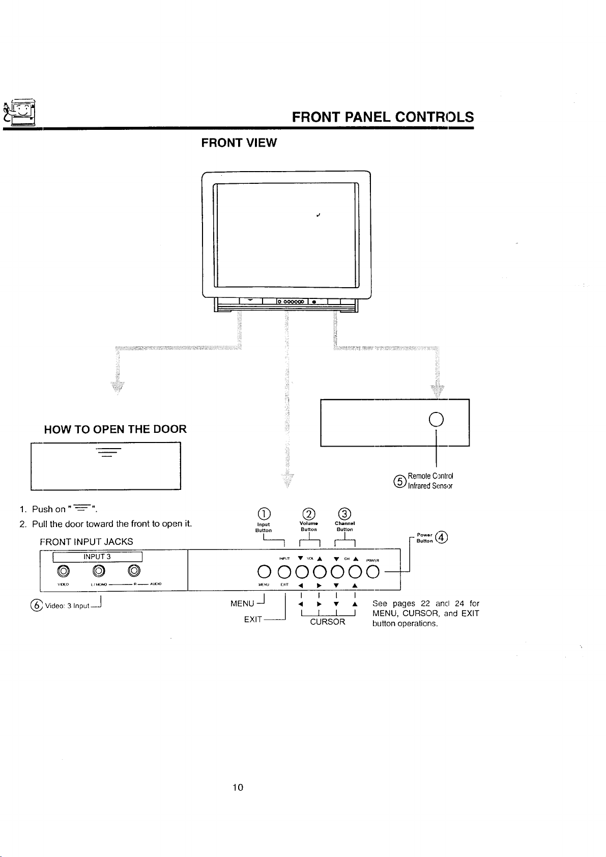
FRONT VIEW
FRONT PANEL CONTROLS
HOW TO OPEN THE DOOR
1. Push on " ---=- "
2. Pull the door toward the front to open it.
FRONT INPU]- JACKS
I INPUT3 I
@ @ ©
v,€_o 11l_oNo-- R -- Au_
Video: 3 Input--J
®
Input
Button
I__
OOOOOOO--
MENU <
J I I I I I
EXIT _
O
I--
(_) Rem0teControl
InfraredSensor
@ ®
Volume Channel
Button Butlon
_- • • o_.e pages 22 and 24 for
I
I I I MENU, CURSOR, and EXIT
CURSOR button operations.
10
Page 11
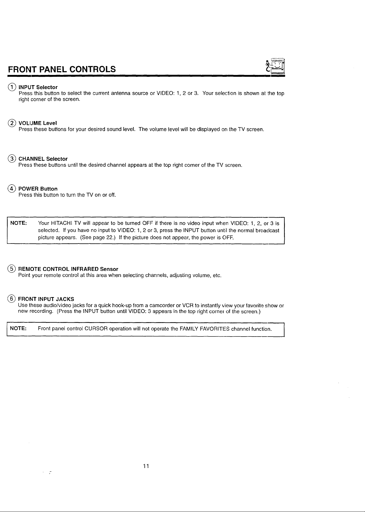
FRONT PANEL CONTROLS
(_ INPUT Selector
Press this button to select the current antenna source or VIDEO: 1, 2 or 3. Your selection is shown at the top
right corner of the screen.
(_ VOLIJME Level
Press these buttons for your desired sound level. The volume level will be displayed on the TV screen.
(_) CHANNEL Selector
Press these buttons until the desired channel appears at the top right corner of the TV screen.
(_) POWER Button
Press this button to turn the TV on or off.
NOTE:
(_ REMOTE CONTROL INFRARED Sensor
Point your remote control at this area when selecting channels, adjusting volume, etc.
(_ FRONT INPUT JACKS
Use these audio/video jacks for a quick hook-up from a camcorder or VCR to instantly view your favorite show or
new recording. (Press the INPUT button until VIDEO: 3 appears in the top right corner of the screen.)
NOTE:
Your HITACHI TV will appear to be turned OFF if there is no video input when VIDEO: 1, 2, or 3 is
selected. If you have no input to VIDEO: 1, 2 or 3, press the INPUT button until the normal broaclcast
picture appears. (See page 22.) If the picture does not appear, the power is OFF.
Front panel control CURSOR operation will not operate the FAMILY FAVORITFS channel function.
]
11
Page 12
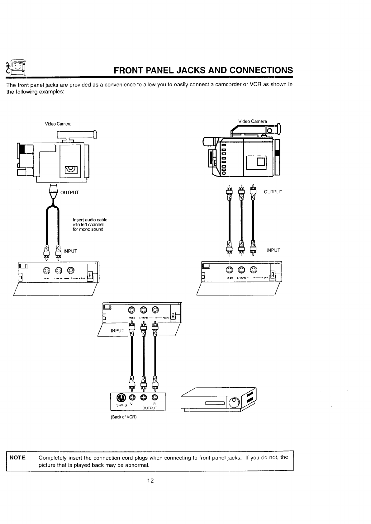
FRONT PANEL JACKS AND CONNECTIONS
The front panel jacks are provided as a convenience to allow you to easily connect a camcorder or VCR a_;shown in
the following examples:
Video Camera
_ OUTPUT
_I'Li INPUT
0
Insert audio cable
into left channel
for mono sound
Video Camera
OIJTPUT
INPUT
,,._to
NPUT
@ooo
S-VHS V L R
(Back of VCR)
OUTPUT
I
NOTE: Completely insert the connection cord plugs when connecting to front panel jacks. If you do not, the
picture that is played back may be abnormal.
12
Page 13

REAFI PANEL JACKS
AUDIO to HI-FI OUTPUT 1_3)
TERMINALS
INPUT TERMINALS O
AUDio
INPUT 2 NPUTI "_
VIDEO VIDEO
©©
©
@
VH FlU H F
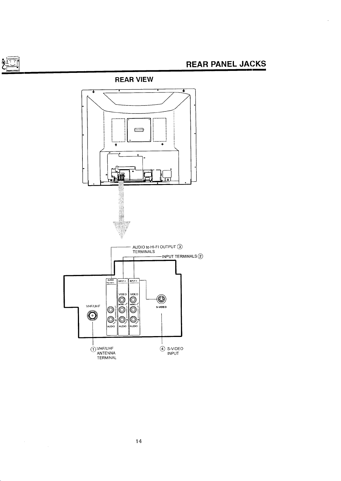
Q VHF/UHF ANTENNA TERMINAL
(_ Antenna Inputs
The VHF/UHF terminal can be used for normal TV, cable TV (CATV), a TV game, etc.
Q
AUDIO
AUDIO AUDtO
Q S-VIDEO INPUT
--@
S-VIDEO
(_ Auclio/Video Inputs 1, 2, 3
The INPUT button will step through each video source and the current antenna input each time it is pressed. Use
the audio and vMeo inputs to connect external devices, such as VCRs, camcorders, laserdisc players, video
games, etc.
(_) Audio to Hi-Fi
These jacks provide variable audio output to a separate stereo system amplifier. With this connection, the audio
to tile stereo can be controlled by the television's remote control. Use these jacks for tile SURROUND [.eft and
Flight channels. (See pages 16 and 19.)
I_ S-Video
Input 1 provides S-Video (Super Video) jacks for connecting equipment with S-Video output capability.
TIPS ON REAR PANEL CONNECTIONS
The S-Video connection is provided for high performance laserdisc players, VCRs etc., that have this feature. Use
this connection in place of the standard video connection if your device has this feature.
If your clevice has only one audio output (menD sound), connect it to the left audio jack on the TV.
Refer to the operating guide of your other electronic equipment for additional information on connecting your hookup
cables.
A single VCFI can be used for VCR #1 and VCR #2, but note that a VCR cannot read its own video or line output
(INPUT: 1 in the example on page 15). Refer to your VCR operating guide for more information on line input-output
connections.
13
Page 14
REAR VIEW
REAR PANEL JACKS
!.
VHF/UHF
/
VHF/UHF
(_) ANTENNA
TERMINAL
-- AUDIO to HI-FI OUTPUT
TERMINALS
INPUT TERMINALS (_
.i k
,AUTO AUO_O
(_ S-VIDEO
INPUT
14
Page 15
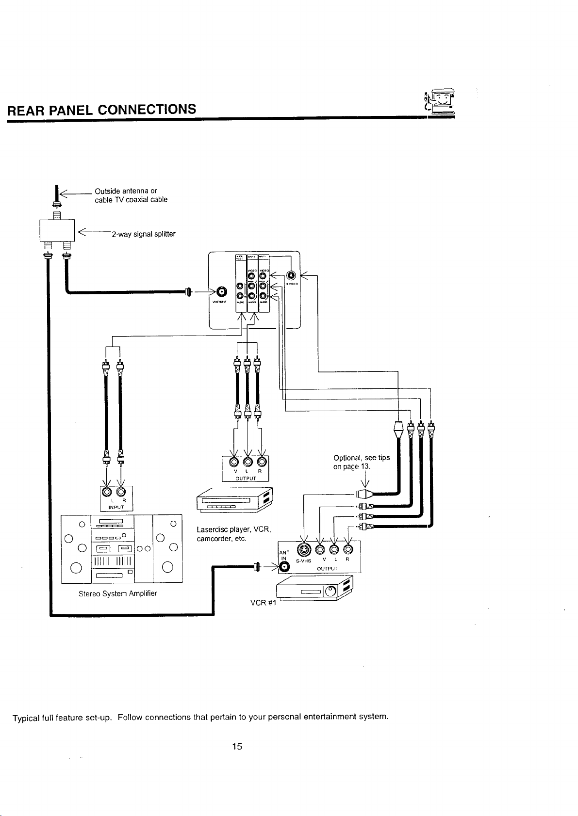
REAR PANEL, CONNECTIONS
cable TV coaxial cable
.__ Outside antenna or
F=:t
I-_ ÷-- 2-woys,gna,sp,..er
i i
--_-- -- I Optional, see tips
OUTPUT _
camcorder, etc.
on page 13.
_oo 0
ll_llt_lll_i I Ot
° L_.L__ _
Stereo System Amplifier
Typical full feature set-up. Follow connections that pertain to your personal entertainment system.
15
I/ _=_1©_
VCR #1
Page 16
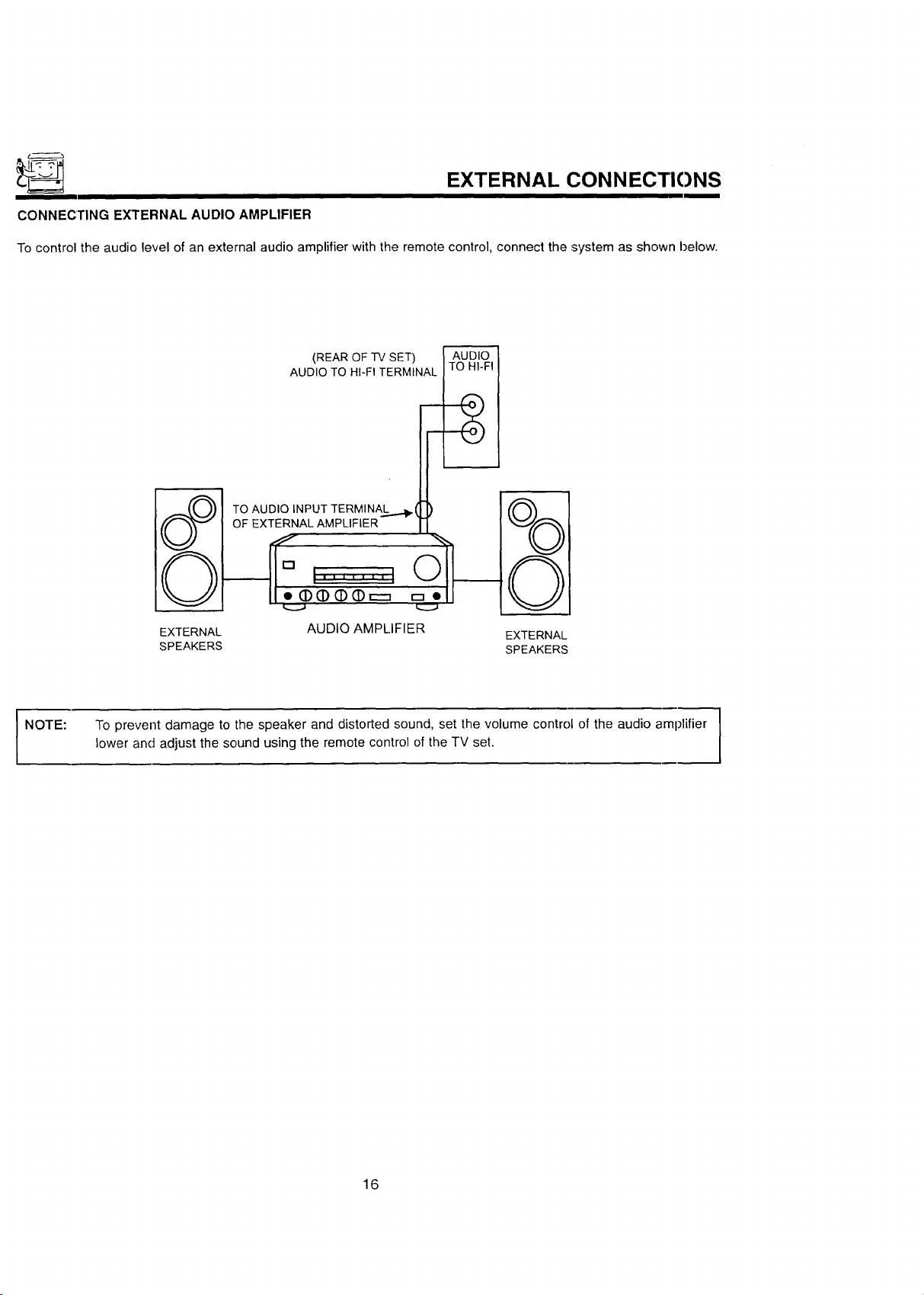
EXTERNAL CONN ECTIONS
CONNECTING EXTERNAL AUDIO AMPLIFIER
To control the audio level of an external audio amplifier with the remote control, connect the system as shown below.
(REAROF-IV SET) AUDIO
AUDIO TO HI-FI TERMINAL TO HI-FI
TO AUDIO INPUT TERMINA.._..._(
OF EXTERNALAMPLIFIER
NOTE:
EXTERNAL AUDIO AMPLIFIER
SPEAKERS SPEAKERS
To prevent damage to the speaker and distorted sound, set the volume control of the audio amplifier |
lower and adjust the sound using the remote control of the TV set.
EXTERNAL
1
1
16
Page 17

CONNECTING EXTERNAL VIDEO SOURCES
I
The exact arrangement you use to connect the Video Cassette Recorder, Video Disc Player and Video Camera to your
TV set is dependent on the model and features of each component. Check the owner's manual of each component
for the Io('ation of vide() and audio inputs and outputs.
The following connection diagrams are offered as suggestions. However, you may need to modify them to accom-
modate your particular assortment of components and features. For best performance, video and audio cabPes should
be made from coaxial shielded wire.
Before Operating External Video Source
The input mode is changed every time the INPUT button is pressed as shown below. Connect external source to the
INPUT terminal, then press the INPUT button as necessary to view the input source. (See page 22.)
INPUT MODE SELECTION ORDER
(Antenna) [Input)
12 I >1 VIDEO
NOTE:
CONNECTING MONAURAL AUDIO VCR OR VIDEO DISC PLAYER
1. Connect the cable from the VIDEO OUT of the VCR or the Video Disc Player to the INPUT (VIDEO) jack on the
TV set below.
2. Connect the cable from the AUDIO OUT of the VCR or the Video Disc Player to the INPUT (MONO)/L(AUDIO)
jack.
3. Press the INPUT Lluttonto view the program from the VCR or Video Disc Player. The VIDEO mode disappears
automatically after approximately eight seconds.
4. Press the INPUT button to return to the previous channel.
When the TV is set to VIDEO and a video signal is not received from VIDEO INPUT JACK on the jack
panel of the TV (i.e., VCR/Video Disc Player, etc. is not connected or the video device is OFF:), the
screen will be grey-blue.
VCR
f ",,,,
"IV INPUT
TERMINAL
INPUT
VIDEO
l | I IlOl II I /
_DEOOUT AL_OOUT
©
[MQNO)
AUDIO
II I[
17
Page 18

CONNECTING EXTERNAL VIDEO SOURCES
CONNECTING STEREO VCR OR STEREO VIDEO DISC PLAYER
1. Connect the cable from the VIDEO OUT of the VCR or the Video Disc Player to the INPUT (VIDEO) jack on the
TV set below.
2. Connect the cable from the AUDIO OUT R of the VCR or the Video Disc Player to the INPUT(AUDIO/R) jack.
3. Connect the cable from the AUDIO OUT L of the VCR or the Video Disc Player to the INPUT(AUDIO/L) jack.
4. Press the INPUT button to view the program from the VCR or Video Disc Player. The mode VIDEO disapl:ears
automatically after approximately eight seconds.
5. Press the INPUT button to return to the previous channel.
VCR
"IV INPUT
TERMINAL
INPUT
VIDEO OUT /_OIO OUT
VIDEO
@
MONOI
AUDIO
NOTE:
OO
"13,rINPUT
TERMINAL
II I I
S-VHS V L R
OUTPUT
BACK OF VCR
Completely insert the connection cord plugs when connecting to rear panel jacks. The picture that is
played back will be abnormal if the connection is loose.
If you have an S-VHS VCR, use the S-INPUT cable in place of the standard video cable.
A single VCR can be used for VCR #1 and VCR #2, but note that a VCR cannot record its own video or
line output, (INPUT: 1 in example on page 15.) Refer to your VCR operating guide for more informa-
tion on line input-output connections.
HITACHI MODEL'krI"-ST51,_,
{)r similar model
18
Page 19

AUDIO SYSTEM SET-UP c_
Match the numbers below to the diagram for speaker placement and refer to the table for the different surround sound
requirements. (See page 48 for SURROUND functions.)
The television's internal speakers.
These speakers are connected to a separate audio amplifier. Use the Audio to Hi-Fi output on the TV.
II
o_. _ i
I
SURROUND
FEATURE
OFF
SIMULATE
MUSIC _ _ -- Surround channel added to left and right audio
MOVIE _ _ -- added to left and right audio amplifier speaker,,
REQUIRED OPTIONAL
CONNECTION CONNECTION
@ @
Receive mono and stereo sound.
At mono input, sound will be louder.
At stereo input, sound of music will be louder.
amplifier speakers.
Movie theater reproduction, surround channel
19
EFFECT
Page 20

_ THE REMOTE CONTROL (CLU-418U)
In addition to controlling all the functions on your HITACHI Color "iV, the new remote control is designed to operate dif-
ferent types of VCRs, CATV (Cable TV), and satellite converters with one touch. Basic operation keys are grouped
together in one area.
To operate your TV, point the remote control at the remote sensor of the TV and press the TV button. The remote will
now cont:ol your TV.
To operate your VCR, point the remote at the remote sensor of the VCR and press the VCR button. The remote will
now cont:ol your VCR. (See page 28 for instructions on how to program the remote to control your VCR.)
To operate your cable/satellite box, point the remote at the remote sensor of the cable/satellite box and press the
CABLE button. The remote will now control your cable/satellite box. (See page 30 for instructions on how to program
the remote to control your cable/satellite box.)
tr
5
:G @9
HELP THEATER TVNCR
I I
I REC _ PAUSE I,
HOME
®
These buttons allow the remote to control your TV,
@
VCR, or cable/satellite box depending on which
mode is chosen, as explained above.
TV/VCR Button
®
When the remote is in the TV or VCR mode, this is
the TVNCR button. When the remote is in the
CABLE/SATELLITE mode, this is the A!B bt,tton.
PRECODED VCR Buttons
®
These buttons always transmit the chosen precoded
VCR codes.
VOL _ CH
C) C) (D
C)
C) (D (D
INPUT SLEEP
OGO
HITACHI
CLU_,lSU
HELP Button
®
Press this button if help is needed to chang_ menu
settings, and our context-sensitive Help system will
provide explanations and/or directions for wl_atever
function your cursor is on at that time.
(_ HOME THEATER Button
This button allows direct access to tile SUR-
ROUND functions.
2O
Page 21

HOW TO USE THE REMOTE TO CONTROL YOUR TV
A detailed explanation of the circled numbers follows on page 22 to 24.
I
®
®
®
®
®
®
I
I
ii_ ¸_
INPUT I I SLEEP
©,,_', ©
HITACHI
CLU-418U
®
®
J
21
Page 22

HOW TO USE THE REMOTE TO CONTROL YOUFI TV
_TV POWER Button
Pre,';s this button to turn the TV set on or off. If ON/OFF TIMER is set, it wilt be displayed when the TV is first
turned on. (See page 42.)
(_ SLE'.EP Button
Pre.';s this button to display the SLEEP TIMER in the lower left corner of the screen. Every subsequent press of
this button will add 15 minutes to the timer, up to a maximum of three hours.
_) MENU, CURSOR Buttons
All On-Screen Display features can be set or adjusted by using these buttons.
The MENU button will start the On-Screen Display.
The CURSOR buttons will highlight functions or adjust and set different features. Pressing the cursor buttons will
also give you access to the FAMILY FAVORITES CHANNELS On-Screen Display.
(_ CHANNEL SELECTOR Buttons
Enter two or three numbers to select channels. Enter 0 first for channels 1 to 9. For channels 100 at'ld above,
press the "1" button and wait for two seconds before pressing the last two digits of the channel.
Channel selection may also be performed by pressing CH up (A) or down (V).
You may also use these buttons for channel scanning. Press and hold the CH up (A) or down (V) bLtttons and
the TV will start quickly scanning through the channels. Release the CH up (,&) or down (Y) buttons when the
TV .';cans to the channel you wish to watch and the TV will tune to that channel.
I NOTE: The TV may not receive some channels if you are not in the correct SIGNAL SOURCE mode. (See
page 35.)
(_ INPUT Button
The INPUT button will select between the antenna signal and the video input jacks each time the button is
pressed. If the Picture-in-Picture (P-in-P) is on, the INPUT will not select any source signal on the main picture.
However, if the P.-in-P is on, the INPUT will alternate between the main signal source and the input source on the
sub-picture. (See picture below and page 25.)
STEREO 28
ESPN
INPUT
VIDEO:I
INPUT
I' I
INPUT INPUT
I
INPUT
CD
STEREO 28 PIP
INPUT
22
STEREO 28
28
ESPN
Page 23

HOW TO USE THE REMOTE TO CONTROL YOUR TV
_} VOLIJME, MUTE Buttons
Press the VOLUME" up (A) or down (V) button until you obtain the desired sound level.
To turn the sound off instantly to answer the telephone, etc., press the MUTE button. Press the MUTE- button
again or press the 'VOLUME up (A.) button to restore the sound.
i
STE _EO 28
45111111tlllllllllllllllllll...,..'..,'..,
VOLUME
"MUTE" will remain displayed if the CLOSED CAPTION feature is turned off.
"MU77E"will not be displayed if the CLOSED CAPTION feature ison.
MTV
llllllllllllllllllllllllllllll....'J,........,
LAST CHANNEL {LST-CH) Button
Use this button to select between the last two channels viewed. (Good for watching two sporting events, etc.)
STEREO 28
PRME
ST/SA
LST-CH
<
©
STEREO 39
(_ PICTURE-IN-PICTURE
See page 25 for a description.
23
Page 24

HOW TO USE THE REMOTE TO CONTROL YOUR "IV
O HOME THEATER Button
Press the HOME 'THEATER button to directly access the SURROUND function. (See page 48.)
(_) EXIT/RECALL/COMMERCIAL SKIP (CS) Button
Press this button when no menu is displayed, when you want to check the channel being received, or if it has
stereo (ST) or second audio (SAP).
You can also check the time, CHANNEL ID, and if the SLEEP TIME has been set.
When in MENU mode, this button will exit all On-Screen Displays.
Press this button twice quickly, when no menu is displayed, to enable the COMMERCIAL SKIP (CS) function.
This will tune the ]-V to the last channel viewed and after 30 seconds, tune back to the original channel.
Audio Selected
I / Channeland
STE_R_s_I_/ AntennaSource
ST/SA
Broadcast
7:00 AM
10:15
If a video input is used:
Video Input
J
VIDEO:I
J
-_. WhenanS-Video
(S-IN)
inputisconnected
You can also use the RECALL button to quickly clear many of the other On-Screen Displays.
24
Page 25

)ICTURE-IN-PICTURE (PIP) _;'_
['he Picture-in-Picture feature is convenient when you want to watch more than one program at the same time. You
"an watch a TV program while viewing a VCR program (TV or tape) on the video inputs.
Bac_ of _,
TV m
AUDIONIDEO INPUT
v_Eo
>0
@I
AuDio
I
I
IvO*Ol
Back of VCR
OUTPUT
t, R
@
_ P-IN-P Button
Press the PIP button and a sub-picture appears in one corner of the screen. Press the button a second time to
remove the sub-picture from the screen. The TV channel will always be either the main picture or the sub-picture.
Main Picture
J PIP STEREO_
PIP
Sub-Picture
@SWAP Button
If you wish to switch what is being shown on the main picture to the sub-picture, press the SWAP button.
PIP STEREO 31
V NEWS
ST/SA
SWAP
25
Page 26

PICTURE-IN-PICTURE
(_ MOVI" Button
To move the sub-pic-tureto any location ofthe screen, press the MOVE buttononce and quicklypress the CURSOR
buttons.
MOVE CURSOR
0"
To move the sub-picture to another corner, press the MOVE button twice quickly. The sub-picture moves one=step
counterclockwise every time the MOVE button is pressed twice.
MOVE
(_ FREFZE (FRZ) Button
If you wish to freeze the sub-picture, press the FRZ button. This is convenient when trying to write down the
address for a mail order company, recording statistics for a sporting event, etc. To return the picture to motion,
press the same button again.
(_ FREI'ZE (FRZ) Button (without a sub-picture (PIP OFF))
Press this button without a sub-picture to freeze the picture you are currently viewing. Press this button again to
return to normal viewing. The SWAP button will not work with this FREEZE function.
31
FRZ
AUTION: A pattern burn may develop if the sub-picture is left in the same corner permanently. If the PIP |
NOTE: 1. Only sound from the main picture can be heard.
2. Picture-in-Picture will not work with a CHILD LOCK channel as the main picture but will be displayed
3. When the PIP button is pressed, the sub-picture will appear in the same position as previously set.
feature is used frequently, occasionally move the sub-picture to a different corner.
as a sub-picture.
1
]
26
Page 27

JSING THE REMOTE TO CONTROL VCR FUNCTIONS
detailed explanation of the circled numbers follows on page 28.
®
®
@
8
,
PiP SWAP MOVE -FIZZ nI I
I
,0000::
r
- I
I REC PAUSE
®
I
®
®
, (D'
I
@@ (D
!
:C)_,(D_@D
INPUT SLEEP
O[QIO
HITACHI
CLU-418U
27
®
®
Page 28

• USING THE REMOTE TO CONTROL VCR FUNCTIONS
Operating the precoded function for your VCR
This remote is designed to operate different types of VCRs. You must first program the remote to match the remote
system of your VCR. (Refer to page 31.)
1. Turn on your VCR.
2. Aim the remote control at the front of your VCR.
3. Press the VCR button to switch to the VCR precoded mode.
4. While holding down the VCR button on the remote, enter the two digit preset code that matches your VC;R as
shown on page 31. The remote will turn off your VCR when the correct two digit preset code is entered. When
this occurs, the remote control is programmed for your VCR. If the VCR does not turn off after five seconcIs, try
a different two digit preset code.
5. The remote will now control your VCR.
NOTES:
1. If yoLJrVCR cannot be operated after performing the above procedures, your VCR code has not been precod-
ed into the remote
2. In the unlikely event that your VCR cannot be operated after performing the above procedures, please consult
your VCR operating guide.
3. The remote control will remember the codes you have programmed in until the batteries are removed from the
remote control. Alter replacing the batteries repeat the entire programming procedure stated above.
4. If your VCR does not have a power function, the remote will issue the CHANNEL UP (A',I function.
(_VCR Button
This allows the remote to control your VCR by setting it to VCR mode.
(_ PRECODED VCR Buttons
These buttons transmit the chosen precoded VCR codes. For some VCRs, you must press the RECORD button
twice to record a program.
_) EXCLUSIVE TV Buttons
These buttons are for operating the TV.
l NOTE: Refer to the instruction manual of the VCR for operation of the buttons exclusively for the VCR.
28
Page 29

USING THE REMOTE TO CONTROL CABLE/SATELLITE
BOX FUNCTIONS
A detailed explanation of the circled numbers follows on page 30.
©
®
r "- - '-HOME _
HE_P : THEATER I TVNCR
®
! plP sw_ Mov_--F_ _
REC PAUSE
©_©
®
®
t /
--MU-i"E--lOllI_
:C_::__(D@:
INPUT SLEEP
©@,©
1
L_ __ __ _
HITACHI
CLU-418U
I
®
I
J
29
Page 30

USING THE REMOTE TO CONTROL CABLE/SATELLITE
Operating the precoded function for your cable/satellite box.
This remote is designed to operate different types of cable boxes and Digital Satellite System.,;. You must first program
the remote to match the remote system in your cable/satellite box. (Refer to page 31.)
1. Turn on your cable/satellite box.
2. Aim the remote control at the front of your cable/satellite box.
3. Pres.'; the CABLE button to switch to cable/satellite box mode.
4. While holding down the CABLE button, enter the two digit preset code that matches your cable/satellite box as
shown on page 3"t. The remote will turn off your cable/satellite box when the correct two digit preset c3de is
entered. When this occurs, the remote control is programmed for your cable/satellite box. If the cable/satellite
box does not turn off after five seconds, try another two digit preset code.
5. The remote will now control your cable/satellite box.
NOTES:
1. If yo_Jr cable/satellite box cannot be operated after performing the above procedures, your cable/satellite box
code has not been precoded into the remote.
2. In the unlikely event that your cable/satellite box cannot be operated after performing the above procedures,
please consult your cable/satellite box operating guide.
BOX FUNCTIONS
3. The remote control will remember the codes you have programmed in until the batteries .are removed from the
remote control. After replacing the batterie s, repeat the entire programming procedure stated above.
4. Ifyo,Jr cable/satellite box does not have a power function, the remote will issue the CHANNEL UP (&) function.
(_) CAB LE Button
This button allows the remote to control your cable/satellite box by setting it to CABLE/SATELLITE mode.
(_ PRECODED CABLE/SATELLITE BOX Buttons
These buttons transmit the chosen precoded CATV and satellite codes.
(_) TV/VCR Button
When the remote is in CABLE/SATELLITE mode, this is the A/B button.
(_ LST-CH Button
If your cable/satellite box has an enter function, this button will send the cable/satellite box enter code.
(_ EXIT/RECALIJCOMMERCIAL SKIP (CS) Button
If your cable/satellite box does not have a last channel function, this button will send the TV channel reca!l code.
(_ EXCLUSIVE TV Buttons
The.'3ebuttons are for operating the TV.
3O
Page 31

3ABLE:./SATELLITE AND VCR CODES
3ABLE BRAND CODES SATELLITE BRAND CODES
_,BC . .01, 03, 05, 06, 09, 11, 12, 14, 30
t_ntronix ....................... 44
t_rcher .................. 28, 40, 44
_elcor ........................ 31
Sable Star ..................... 31
Sentury ....................... 40
3itizen ........................ 40
3olour Voice ................ 19, 25
3omtronics ................. 29, 34
Sontec ....................... 15
Dae Ryung .................... 06
Eastern ....................... 02
Electricord ..................... 37
Everquest ..................... 13
Focus ........................ 57
Garrard ....................... 40
GC Electronics ............... 31,44
Gemini ............... 13, 32, 36, 46
General Instrument ........... 09, 51
GoldStar ................... 29, 39
Hamlin ............ 08, 16, 27, 49, 50
Hitachi ........................ 09
Hytex ......................... 05
Jasco ......................... 40
Jerrold ...... 03, 09, 10, 12, 13, 30, 51
Macom ....................... 26
Magnavox ..................... 21
Memorex ...................... 00
Movie Time .............. 35, 37, 42
NSC ................... 35, 37, 42
Oak .................... 05, 15, 47
Panasonic ............... 00, 17, 38
Paragon ...................... 00
Philips ............ 19, 21, 22, 23, 24,
................... 25, 40, 46, 54
Pioneer ................. 18, 39, 65
_opular Mechanics .............. 57
Pulsar ........................ 00
RCA ......................... 17
=lealistic ...................... 44
=lecoton ....................... 57
=legal ................ 16, 49, 50, 53
qegency ...................... 02
=lembrandt .................. 09, 36
Runco ........................ 00
3amsung ................... 29, 39
Scientific At anta ....... 04, 06, 14, 52
Signal ..................... 13, 29
-_ignature ...................... 09
3L Marx ...................... 29
Sprucer .................... 17, 55
_tarcom ................. 03, 13, 30
-_targate .................... 13, 29
_tarquest ...................... 13
;tarSight ................... 58, 59
}ylvania ...................... 01
"eleview ...................... 29
-exscan ....................... 01
bcom ........................ 33
bshiba ....................... 00
-usa ......................... 13
-V86 ......................... 35
}nika ...................... 40, 44
}nited Artis[s ................... 05
}nited Cable ................... 03
}niversal ....... 28, 31,37, 40, 43, 44
1ideoway ...................... 48
tiewstar .............. 21,34, 35, 45
:enith ..................... 00, 64
:entek ........................ 57
General Instrument .............. 61
Jerrold ..................... 61, 62
Primestar ................... 61, 62
RCA ......................... 60
Sony ......................... 63
TELEVISION BRAND CODES
Hitachi ........................ 00
Megatron ...................... 00
VCR BRAND CODES
Adventura ..................... 00
Aiko .......................... 50
Aiwa ......................... 00
Akai .................... 14, 23, 49
American High ................... 09
Asha .......................... 48
Audiovox ....................... 10
Beaumark ..................... 48
Bell & Howell ................... 30
Brandt ........................ 38
Broksonic .......... 33, 37, 43, 51,52
Calix .......................... 10
Canon ......................... 09
Capehart ....................... 05
Carver ........................ 28
CCE ...................... 27, 50
Citizen ..................... 10, 50
Colt .......................... 27
Craig ................ 10, 19, 27, 48
Curtis Mathes ............ 09, 14, 22
Cybernex ...................... 48
Daewoo ........... 03, 05, 17, 29, 50
Daytron ....................... 05
Dynatech ...................... 00
Electrohome ................... 10
Electrophonic ................... 10
Emerex ....................... 06
Emerson .... 00, 01, 10, 16, 23, 33, 37,
........... 40, 41, 43, 44, 50, 51,52
Fisher ............... 19, 21, 25, 30
Fuji ....................... 07, 09
Funai ......................... 00
Garrad ........................ 00
GE .................. 09, 22, 24, 39
Goldstar ................. 04, 10, 11
Gradiente ..................... 00
Harley Davidson ................ 00
Harman/Kardon ................. 11
Harwood ...................... 27
Headquarter ................... 18
HI-Q ......................... 19
Hitachi ............... 14, 15, 24, 31
Jensen ....................... 14
JVC .................... 02, 14, 26
KEC ...................... 10, 50
Kenwood ................ 11, 14, 26
KLH .......................... 27
Kodak ...................... 9, 10
Lloyd ......................... 00
Lloyd's ........................ 40
Logik ......................... 27
LXI .......................... 10
Magnovox ......... 09, 12, 28, 32, 34
Magnin ....................... 48
Marantz .................... 09, 28
Marta ......................... 10
Matsushita ..................... 09
VCR BRAND CODES
(Cont.)
MEI ......................... 09
Memorex .......... 00, 09, 10, 12, 18,
................... 19, 20, 30, 48
MGA ...................... 16, 23
MGN Technology ................ 48
Minolta .................... 15, 31
Mitsubishi .......... 16, 23, 26, 36, 49
Motorola ................... C9, 20
MTC ...................... C0, 48
Multitech ................... C0, 27
NEC .............. 11, 13. lZl, 26, 30
Nikko ......................... 10
Noblex ........................ 48
Olympus ................... (:9, 47
Optimus ................. 10, ,cO, 30
Orion ......................... 51
Panasonic ......... 09, 35, 46, 47, 53
Penney ...... (:)9, 10, 11, 13, 15, ,Cl, 48
Pentax .................. 15, ,c4, 31
Philco ........................ 09
Philips .................. 09, 2:8, 32
Pilot ......................... 10
Pioneer ...................... 26
Portland ...................... 05
Protec ....................... 27
Pulsar ....................... 12
Quarter ...................... 18
Quartz ....................... 18
Quasar ...................... 09
Radio Shack ................ 00, 10
Radix ........................ 10
Randex ...................... 10
RCA ........... 15, 22, 24, 31, 34, 39
Realistic .......... 00, 09, 10, 13, 19,
................... 20, 25, 30, 48
Ricoh ......................... 08
Runco ........................ 12
Samsung ................... 17, 48
Sanky ..................... 12, 20
Sansui ..................... 14, 26
Sanyo ............... 18, 19, 30, 48
Scott .......... 16, 17, 33, 37, z,3, 44
Sears ............ 09, 10, 15, 1E3,19,
................... 21, 25, 30, 31
Sharp ........................ 20
Shintom ....................... 27
Shogun ....................... 48
Singer ........................ 27
Sony ................ 06, 07, 08, 09
STS .......................... 15
Sylvania ........... 00, 09, 16, ;!8, 32
Symphonic .................... 00
Tatu ng ........................ 14
Teac ...................... 00, 14
Technics ................... 09, 35
Teknika .................. 00, 09, 10
Telefunken ..................... 38
TMK ...................... 40, 48
Toshiba ................... 17, 25, 44
Totevision ................... 0, 48
Unitech ....................... 48
Vector ........................ 17
Vector Research ............. 11, 13
Video Concepts ........... 13, 17, 23
Videosonic ..................... 48
Wards ......... 00, 09, 15, 19, 20, 22,
................... 27, 34, 44, 48
XR-1000 ............... 00, 09, 27
Yamaha ....................... 11
Zenith ........................ 08, 12
31
Page 32

co.o.G.AP.,cGU,OE
I
With HITACHI'S On-Screen Display, each category has it's own color and icon. This semi-transparent system includes
SET-UP, CUSTOMIZE, VIDEO, AUDIO, and INFO CENTER categories. Using the four cursor buttons, you c-an eas-
ily access and control all of the TV's functions. Checked boxes let you so that you know which function you have cho-
sen. You can also choose to access the menu in English, French, or Spanish.
1. Press IvlENU on the remote control to display the different features on
your HITACHI TV.
2. Press !:he CURSOR buttons to highlight and select different features.
3. Press EXIT on the remote control to quickly exit from a menu.
4. Press HELP on the remote control when a menu is displayed, and text
will ap13eargiving a description of that menu.
This I:,artof the screen shows
what ,_elections are available.
>
[_ SET-UP
[_ CUSTOMIZE
[_ VIDEO
AUDIO
INFO.
CENTER
A TO _1_SELECT EXIT
This part of the screen shows which
remol:e control buttons to use.
>
• MOVE (QUIT MENU
CURSOR
HELP
J
J 000000 J
AUTO-DEMONSTRATION
This feature will demonstrate how to use and set up your HITACHI television. To perform this feature, pres:_ the front
panel POWER button and hold for five seconds. The On-Screen Display will appear on your TV set demonstrating
the settings of your TV feature.
To exit AUTO-DEMONSTRATION, press the power button on the front panel of the TV, which will turn t_qeTV off.
Press the power button again to turn your TV set on and resume normal operation.
NOTE:
On some televisions, the SHIFT and EXCHNG that appear during the auto-demonstration are equiva-
lent to the MOVE and SWAP button respectively on your remote control.
In most cases, the MENU button is used to enter and exit the On-Screen Display.
32
Page 33

COLOR GRAPHIC GUIDE
sET'uPI
cusToM,zE
_1 VIDEO
II7],u ,o ]
MENULANGUAGE
SIGNALSOURCE
AUTO CHANNELSET
f
CHANNELADD/DEL
CHANNELLIST
CLOCK SET
CHANNEL ID
FAMILY FAVORITES
CHILD LOCK
OPTIONS
/ ONIOFF TIMER
_CLOSED CAPTION
CONTRAST
BRIGHTNESS
COLOR
TINT
SHARPNESS
COLOR TEMP.
RESET
BASS
TREBLE
BALANCE
I
RESET
ADVANCED
SETTINGS
VOLUME
CORRECTION
SURROUND
Choose English,French,or Spanish language.
Select Antenna or cable TV.
First time set up for channel buttons.
Add or delete channel.
Check channel name, scan, and chilcl Icck.
Set before using timer features.
Label channels PAY1, ABC, etc.
Store family favorites channels.
Block channel picture and sound.
Turn TV on or off onc'e, daily, or weekly.
Feature to display dialogue/text.
Adjust contrast.
Adjust brightness.
Adjust color.
Adjust tint.
Adjust sharpness.
Adjust warm (red tones) or cool (blue tcnes).
Set VIDEO to factory preset condition.
Adjust bass.
Adjust treble.
Adjust balance.
Set AUDIO settings to,factory preset condition.
Improve sound performance.
Lower volume on selected channels.
Special sound effects,
I_l-i-i-_1 INFO. I
!_ CENTERI
""= MESSAGES
Used to leave message or daily reminder.
33
Page 34

SET-UP
Select SET-UP when setting your TV up for the first time.
Use the CURSOR •,Y
buttons on the remote to highlight the function desired.
MENU LANGUAGE This feature will allow you to select any one of three different languages for all On-S;reen
Displays.
E:F
CUSTOMIZE
VIDEO
t SET-UP 1
18 'c" °TER
A TO _'SELECT EXIT |
• MOVE (QUIT MENU)_
SET-UP 1
MENU LANGUAGE
SIGNAL SOURCE
AUTO CHANNEL SET |
CHANNEL ADD/DEE l
CHANNEL LIST I
CLOCK SET j
• TO _1_SELECT |
• MOVE BACK (QUITMENU)_
CURSOR
Use CURSOR • or • to select the MENU LANGUAGE of your choice.
Press EXIT to quit menu or CURSOR < to return to previous menu.
MENU LANGUAGE
_t'31 ENGLISH
[] FRANCAIS
[] ESPANC)L
• TO (QUIT MENUIMOVE '_ BACK
34
Page 35

SET-UP
I SIGNAL SOURCE
LCURSOR
Select ANTENNA if you are using an indoor or outdoor antenna. Select CATV if you have
cable TV.
I [__TSET,UP _J
I_ CUSTOM,ZE
I[# V,OEO
1[] AUDIO
I_ ,NFO.
CENTER
• TO 1_SELECT EXIT )J
• MOVE {QUIT MENU
MENU LANGUAGE
SIGNAL SOURCE
AUTO CHANNEL SET
CHANNEL ADDIDEL
SET-UP l
CHANNEL LIST
CLOCK SET
{€ TO,'SELEOT_x_r_
MOVE '_ BACK (QUITMENU
CURSOR SIGNAL SOURCE !
_-DIANTIENNA
E}CA'I'V1
[] CATV2
EXIT
I, "° = -olMOVE '_ BACK
Press CURSOR • or • to highlight and select the correct SIGNAL SOURCE mode.
Press EXIT to quit MENU or CURSOR • to return to previous menu.
RECEPTION BAND
CATV 1 OR CATV 2
#NTENNA
VFIF2 ~ 13ch
UHF 14- 69ch
CATV CHANNEL Indicated on
the screen
VHF2 - 13
Mid band A- I
A-5 - A-1
Super band J - W
Hyper band
W+I -W+28
Ultra band
W+29-W+84
2-13
14 - 22
95 - 99
23 - 36
37 - 64
65-125
Reception channels for each mode are shown at the
left.
Refer to your cable or TV guide for channel identifi-
cation standards.
If certain CATV channels are poor or not possible in
CATV1 mode, set SIGNAL SOURCE to CArV2.
35
Page 36

SET-UP
LAUTO SET ] This feature will automatically store active TV channels in CHANNEL ADD/DEL. This will
CHANNEL
Jallow you to skip over unused channels when using the CHANNEl. UP (A) or DOWN (V)
buttons.
MENU LANGUAGE
SET-UP t
SIGNAL SOURCE
AUTO CHANNEL SET _1
CHANNEL LIST
CHANNEL ADD/DEL j
CLOCK SET
I A TO _I_SELECT EXIT |
• MOVE • BACK (QUITMENU)_
AUTO CHANNEL SET CURSOR
]1_1-1BEGIN _.._(_ I_ _
[
_I_SELECT•BACK (QUIT MENU)]
EXIT
[
AUTO CHANNEL SET ]
[] INSTALLING
CHANNELS 100
50'/= COMPLETE j
L
If the EXIT button is pressed while the AUTO CHANNEL SET function is engaged, programrning will stop.
Remember to select the correct SIGNAL SOURCE mode before using AUTO CHANNEL SE'F.
See CHANNEL ADD/DIEL to add or erase additional channels.
36
Page 37

SET-UP
I CHANNI-L ADD/DEL I
Use this function after AUTO CHANNEL SET to add or erase additional channels to the
remote control CHANNEL • or • buttons.
MENU LANGUAGE
SIGNAL SOURCE
SET-UP t
AUTO CHANNEL SET
CHANNEL ADD/DEE
CHANNEL LIST [
CLOCK SET
• TO II_SELECT EXIT ]
• MOVE • BACK (QUIT MENU)J
i CURSOR
-qE)
CHANNEL ADD/DELETE
CHANNEL 03
E_IADD DDELETE
__ NEXT CHANNEL C_
€ NEXT _1_SELECT EXIT I
CH • BACK (QUIT MENU)I
CURSOR CHANNEL ADD/DELETE !
i€ NEXT _.SELECT EXIT
CHANNEL 03
[_ADD r',IDELETE
NEXT CHANNEL CH• CH__I
CH • BACK (QUIT MENU)
Add or er;ase additional channels while still in CHANNEL ADD/DEL using CURSOR • or •, CHANNEL • or T, and
number buttons and then add or erase using the CURSOR • button.
Press EXIT to quit menu or CURSOR "_ to return to previous menu.
37
Page 38

SET-UP
CHANNEL LIST
I This function allows you to view which channels are labeled in CHANNEL ID (NAME-), which
have been added to CHANNEL ADD/DEL (SCAN), and which are protected b!/ CHILD
LOCK (LOCK).
MENU LANGUAGE
SIGNAL SOURCE
AUTO CHANNEL SET
CHANNEL ADD/DEL
SET-UP l
CHANNEL LIST
CLOCK SET
I€ TO • SELECT EXIT |
MOVE '_ BACK (QUIT MENU)]
CURSOR
Press CURSOR • or V to view more channels.
Press EX;!T to quit menu or CURSOR 4 to return to previous menu.
CLOCK SET
Use this feature for all time related functions. The time must be set before you can use the
ON/OFF TIMER or MESSAGE.
CHANNEL UST
CH NAME SCAN LOCK
01 USA ON --
02 ROLY ON
03 TESS - ON
04 JAYB - ON
05 JEKO - -
[€,o
MOVE • BACK (QUIT MENU
._
MENU LANGUAGE
SIGNAL SOURCE
AUTO CHANNEL SET
SET-UP I
CHANNEL ADD/DEL
CHANNEL LIST
CLOCK SET
€ TO •SELECT EXIT |
MOVE <BACK (QUIT MENU)J
CURSOR
Use CURSOR • or • buttons to set the time and AM or PM.
Press CURSOR • to change position.
Press EXIT to quit menu or CURSOR • to return to previous menu.
38
CLOCK SET j
TIME 12 : 00 PM
• TO • SELECT EXIT 1
• SET • BACK (QUIT MENU
Page 39

CUSTOMIZE
This selection contains advanced features which will make TV viewing easier and
I[_ cUsTOMIZE
CHANNEL ID Use this feature to name up to 25 channels.
FAMILY
FAVORITES
CHILD LOCK
OPTIONS
ON/OFF TIMER
CHANNEL ID l
CLOSED
CAPTION
more enjoyable.
CUSTOMIZE ]
CURSOR
[. To •SELECT
MOVE _ BACK (QUITMENU
Press CURSOR • or • to select letters.
Press CURSOR • to change character position.
Press CHANNEL • or • to select and label additional channels.
Press EXIT to quit menu or CURSOR < to return to previous menu.
The CHANNEL ID will appear in the top right corner of the screen when the RECALL button is pressed.
The (*) represents a blank space.
Select ERASE ID to erase a CHANNEL ID. An "ARE YOU SURE?" display will appear on the screen to confirm your
choice.
I NOTE:
CHANNE'L ID will be displayed only when channel is displayed as main picture.
i A NEXT _SELECT EXIT |
Y CH _ BACK (QUIT MENU)]
]
39
Page 40

II
CUSTOMIZE
I FAMILY
F_NORITES
I With Family Favorites, you can easily access your favorite movie, sports, news, and custom
stations by registering any of your favorite stations into one of four categories. Once you
have input your four favorite stations in each category, you simply press any of the cursor
buttons and the Family Favorite's screen appears. Now you can easily switch between your
16 favorite stations.
CHANNEL ID
FAMILY"
FAVORITES
CHILD LOCK
OPT(ONS
ON/OFF TIMER
CUSTOMIZE l
CLOSED
CAPTION
• TO I_SELECT EXIT ]
• MOVE <BACK (QUIT MENU)]
CURSOR
FAMILY FAVORITES 66
SPORTS
NEWS
CUSTOM
I'_ b" (SET) (QUIT MENU I
MENU EX_
Use CURSOR • or • buttons to highlight the category you wish to register the channel under.
Press CURSOR • to select the column you wish to register the channel under.
Press CHANNEL A or • or the number buttons to enter the desired channel. The channel to be added is displayed
in the top right corner of the screen.
Press MENU button to register your favorite channel.
Repeat until the category has been registered with your favorite channels.
To erase a FAMILY FAVORITES channel, enter O0as channel then press MENU button.
Once your favorite channels are registered in the FAMILY FAVORITES menu, your TV set will change to tna: station
when selected.
Press EXIT to remow._ FAMILY FAVORITES OSD from the SCREEN.
I NOTE:: After all of your favorite channels are registered, the CURSOR buttons can be used for quick 8ccessto the FAVORITE CHANNELS menu.
4O
Page 41

CUSTOMIZE
I CHILD LOCK
OPTIONS
This feature allows you to block out the picture and sound of the selected channel or video
input of any channel that you feel may be inappropriate for your children. There is no limit
to the number of channels that can be locked. Your secret code allows you to reinstate
these channels any time you wish. It can also be used to schedule an amount of time that
the TV cannot be viewed.
CHANNEL ID
FAM ILY
FAVORITES
CUSTOMIZE _'!
CHILD LOCK
OPTIONS
ON/OFF TIMER L
CLOSED
CAPTION 1
TO I_SELECT EXIT
MOVE • BACK (QUIT MENU)_
CURSOR
A CHANGE _SELECT EXIT |
YNUMBER BACK (QUIT MENU_
The code to enter CHILD LOCK is a three digit key number. The factory preset code is 000.
Use CUI:ISOR • or Y to select number or CURSOR I_ to change position.
CHILD LOCK OPTIONS J
I * ** SECRETCODE
I
--I
• CHANGE _SELECT EXiT J
V'NUMBER •BACK (QUIT MENU
C)
C)
(Z£)
1
LCURSOR
Use CLIRSOR • or Y to highlight function and CURSOR l_.to set ON or OFF.
When CHANNEL is turned on, the picture and sound for the chosen channel will be blocked out.
When VIDEO is turned on, the picture and sound for the video input will be blocked out.
When QUICK LOCK is turned on, the picture and sound for'channels 3, 4 and all video input will be blocked out.
When TV TIME OUT is turned on, you can set the BEGIN and END times and the TV cannot be viewed during that
time period.
CHILD LOCK OPTIONS .
ON OFF 10
[] O CHANNEL
[] {_ VIDEO
[] [] QUICK LOCK
_Z] [] TV" TIME OUT
- - : - - AM BEGIN
- - : - - AM END
I * * * CHANGE SECRET CODE
• NEXT _SELECT EXIT
'" CH. "_ BACK (QUITMENU)_
CURSOR
CHILD LOCK ON t
To change the key n,LJmber,select CHANGE CODE. Enter a new three digit key number you prefer.
If you forget your key' number, use the factory code 777 to erase your key number. This will reset the key num3er back
to the f:actory preset 000.
41
Page 42

CUSTOMIZE
ON/OFFTIMER
This function will automatically turn the TV set on or off one time only, every day, or once a
week. It can also be set to turn on to your favorite program, or as a reminder, to turn to your
favorite program when the TV is already on.
CHANNEL ID
FAMILY
FAVORITES
CHILD LOCK
OPTIONS
ON/OFF TIMER
CUSTOMIZE I_'!
CLOSED
CAPTION
TO •SELECT EXIT )]
MOVE '_ BACK (QUIT MENU
CURSOR
,A TO •SELECT EXIT |
• ' MOVE < BACK (QUITMENU)_
ON/OFF TIMER
• -o :--AM TVON
-- : -- AM'I'V OFF
CHANNEL 03
[] ONCE
C3 DAILY
[] WEEKLY
[] OFF
Press CURSOR • or V to select either the ON or OFF TIMER.
Press CURSOR • to highlight selection to be changed.
Press CUF:ISOR • or V to select the time the TV will turn on and off and to choose AM or PM.
Press CURSOR • to exit time setting.
Select CHANNEL and press CHANNEL • or • to set the channel the TV will tune to when it automatically turns on.
Press CURSOR • to exit channel setting.
Press CUI_SOR • or V to highlight then CURSOR • to select mode: ONCE (one time only), DAILY (every day), or
WEEKLY (once a week).
Press EXIT to quit menu or CURSOR < to return to previous menu.
NOTE: You can set either on time only or off time only, or both. The mode will be the same for both.
Ifthe TV is turned on by the ON TIMER and there is no remote control operation in three hours or more,
the TV will automatically turn off.
.3AUTION: Do not use your TV as a deterrent when away from home by using both the ON TIM!--F: and
OFF TIMERS. For safety, the TV should be turned off when you are away from home.
]
1
42
Page 43

CUSTOMIZE
I CLOSED
CAPTION
Closed captions are the dialogue, narration, and/or sound effects of a television programor home video which are displayed on the TV screen allowing you to read l:h_, dialog
being spoken (when broadcast). Your local TV program guide denotes these programs
as r_l or I_.
CUSTOMIZE
CHANNEL ID
FAMILY
FAVORITES
CHILD LOCK
ON/OFF TIMER
CLOSED
OPTIONS
CAPTION
i_ TO •SELECt EXIT t
MOVE 4 BACK (QUITMENU}I
CURSOR
DISPLAY: ON/OFF will turn the IE'EIdisplay on or off.
MODE:
MODE:
C.C. (Closed Caption) is for the program you are viewing.
TEXT is for additional information such as news reports or a TV program guide. This information
covers the entire screen and viewing the TV program is not possible. TEXT may not be available
with every _ program.
CLOSE CAPTION
• DISPLAY [] ON
MODE [] C.C.
CHANNEL [] 1
TO •SELECT EXIT 1
MOVE _ BACK (QUIT MENU
CI OFF
[] TEXT
R2
CHANNEL:
CHANNEL:
1 is used for the primary language (usually English).
2 is sometimes used for a second language (may vary by region).
Use CURSOR • or _' to highlight the function to be changed; press CURSOR • to change the function.
Press E-XITto quit menu or CURSOR ,d to return to previous menu.
Sunny 70"
Weather Tomorrow
A bit cooler 3 °
Wind Chill -55
l eather Today
Text Selected
NOTE:
L
C.C. Selected
The word MUTE will not be displayed if the Closed Caption Display is ON. If you do not have sound,
make .';ure MUTE is not set.
43
Page 44

i Select VIDEO to adjust picture settings and improve picture quality.
VIDEO
SET-UP /
[] CUSTOMIZE L
I!#
I[ q uo,o |
CURSOR
CONTRAST _"==""_"=_"_
BRIGHTNESS ,,.......I...,,.,..,
COLOR ...............i,..,.. ......
TINT m""""=l_"_u"m"_='
SHARPNESS .............,I. ..............
COLOR TEMP. 131WARM
RESET []
E] COOL
[_ NFO:I'ER i
f TO P_ TO EXIT )1
• TO _SELECT EXIT
• MOVE (QUIT MENU
MOVE "ADJUST (QUIT MENU
Use the CURSOR • or • to highlight the functionto be adjusted.
Press CURSOR • or • to adjust the function.
Press EXIT to quit menu or CURSOR • to return to previous menu.
CONTRAST
Use this function to change the contrast between black and white levels in the picture.
BRIGHTNESS
Use this function to adjust overall picture brightness.
COLOR
Use this function to adjust the level of color in the picture.
TINT
Use this function to adjust flesh tones so they appear natural.
SHARPNESS
Use thisfunction to adjust the amount of fine detail in the picture.
COLOR TEMP.
Use this function to adjust the white balance (hue) of the picture to your own color preference.
When shipped from the factory, this is set to COOL. If you prefer a reddish screen, set to WARM.
RESET
When RESET is selected, the "ARE YOU SURE?" display will appear on the screen to confirm your choice.
CURSOR • to return VIDEO adjustments to factory preset conditions.
NOTE:
If CONTRAST is selected you are adjusting CONTRAST, the additional menu items COLOR, 'TINT,
BRIGHTNESS, SHARPNESS, and RESET can be viewed on the screen and can also be adjL_sted by
scrolling through them using the CURSOR • or •. This is also true for all of the menu items in VIDEO.
44
Press
Page 45

AUDIO
Select AUDIO to adjust the TV to your preference and to improve the sound quality.
I
I E_.TSET-UP
I[_ CUSTOMIZE
CURSOR
I V,OEOl_
oo,o
INFO. |
I @ CENTER |
TO _I_SELECT EXIT
_r MOVE (QUIT MENU)
Use the CURSOR • or • to highlight the function to be adjusted.
Press CURSOR • or _- to adjust the function.
Press E.:XITto quit menu or CURSOR • to return to previous menu.
BASS
This function controls the low frequency audio to all speakers.
TREBLE
This function controls the high frequency audio to all speakers.
BALANCE
This function will control the left to right balance of the TV internal speakers and the AUDIO TO HI FI output.
,3A_ _.m,.._......
TREBLE ..........,,,,.I..i,...,,,,
BALANCE .,.,,*,.,;",l',"""" ""
RESET []
ADVANCE
SETTINGS
VOLUME
CORRECTION
SURROUND
A O _, TO ExiT ]
• MOVE • ADJ. (QUITMENU)J
RESET
When !:_ESET is selected, the "ARE YOU SURE?" display will appear on the screen to confirm your choice. Press
CURSOR ),- to return AUDIO adjustments to factory preset conditions.
NOTE': If BASS is selected you are adjusting BASS, the additional menu items TREBLE, BALANCE, and
RESET can be viewed on the screen and can also be adjusted by scrolling through them us ng the
CURSOR • or •. This is also true for all of the menu items in AUDIO.
45
Page 46

AUDIO
ADVANCED
SETTINGS
Use ADVANCED SETTINGS to improve the sound performance of your TV depending on
listening conditions.
MULTI-CHANNEL SOUND
TREBLE
BALANCE
RESET _]
ADVANCE •
I ASS
SETTINGS
VOLUME
CORRECTION
SURROUND
Y MOVE ADJ. (CUrt'MENU
CURSOR
k-TSTEREO MODE
rqMONO
NSECOND AUDIO PROGRAM
ON OFF
[] NOISE CANCELER
[] LOUDNESS
[] [] INT. SPEAKERS
TO _ SELECT EXIT I
MOVE '_ BACK (QUIT MENU
Press CURSOR • or • to highlight a function.
Press CURSOR I_ to change the function setting.
Press EXIT to quit menu or CURSOR • to return to previous menu.
MTS MODE
Multi-Channel Television Sound (MTS) will allow you to select STEREO (Stereo Broadcast), SAP (Second Audio
Program) which may be a secondary language, weather report, etc. or MONO (Monaural Sound) used when receiv-
ing a weak stereo broadcast.
The sources received will be displayed below the channel number. The MTS mode you selected will be displayed to
the left of the channel number. See example below for each selection when both stereo and second audio are
received (monaural is always received).
STEREO SELECTED
STEREO 31
NEWS
ST/SA
SAP SELECTED
SAP 31
NEWS
ST/SA
MONO SELECTED
NEWS
31
NOISE CANCELER
This funclion eliminates the noise in between stations. If a channel is tuned and is noisy, this function will aut3mati-
cally eliminate the audio and video for that channel.
LOUDNESS
This function will improve the quality of both low and high frequency sounds when listening at low volume levels.
INT. SPEAKERS
This function is useful when first setting up the external speakers, or if you prefer to use only speakers from a sepa-
rate stereo system.
46
Page 47

AUDIO
I VOLUME 1
CORRECTION
Use this function to reduce the volume level of up to four channels that sound loud com-
pared to other channels.
BASS IJllllilltl]lllllTI]llllllIIlIIl{
TREBLE ................I................
BALANCE ................I................
RESET []
ADVANCE
SETTINGS
VOLUME
CORRECTION
SURROUND
TO IbSELECT EXIT |
MOVE <BACK (Qurr MENU){
VOLUME CORRECTION 10t
100%
_,_ 100%
NEXT CHANNEL CHACHV
[%TO"SELECT
MOVE "ll BACK (QUIT MENU
100%
CH LEVEL i
100%
CURSOR
VOLUME CORRECTION
CH LEVEL
I_ 00%
NEXT CHANNEL CHACH_F !
A TO _SELECT--_IT_
• MOVE _ BACK (QUffMENU)I
100% 1
100% i
lOO%
10
Press CURSOR • or • to highlight one of the four volume corrections, then CURSOR _ to select.
Press CHANNEL • or • and number buttons to select a channel.
Press MFNU to set the channel to be volume corrected.
Press CURSOR • or • to adjust volume level in 5% increments.
Press EXIT to quit menu or CURSOR • to return to previous menu.
NOTE:
!. Volume Correction adjustment is for the channel display in the top right corner of the screen, To
adjusl: a different channel, you must select the channel with the channel or number button.'; and
press CURSOR _,.
2. If the channel has been corrected before, use the CURSOR • or • to highlight and CURSOF I_ to
select that channel, then use the CURSOR • or • to change the level.
3. To erase a channel from volume correction, select channel 00 and press MENU.
4. The volume level will change from 50% to 100% in increments of 5%.
47
Page 48

AUDIO
SURROUND
The following surround sound settings will reproduce the "live" sound you would hear in
concert halls, movie theaters, etc. when you set up your speaker system as shown in the
section on rear panel connections on pages 15, 16 and 19. The surround system is most
effective with movies played on a stereo VCR.
Surround sound allows the viewer to enjoy sound which provides a feeling of "presence"
from stereo broadcasts and VCR tapes recorded with stereo sound. Also a monc input,
simulating a stereo, will increase the sound giving the listener simulated surround sound.
BASS ................I................
TREBLE .......'""""1 ................
BALANCE ....'"'""""1 ...............'
RESET []
ADVANCE
SETTINGS
VOLUME
CORRECTION
SURROUND •
I- 1
V MOVE ADJ. (QUITMENU
SURROUND
• Z31 OFF
{_ MUSIC
[] MOVIE
[] SIMULATE
CURSOR
SURROUND
[] OFF
• D MUSIC
[] MOVIE
[] SIMULATE
• TO •SELECT (QuEXITNU)ITME
• MOVE • BACK
[_ TO •SELECT EXIT
MOVE • BACK (QUITMENU;
SURROUND OFF
Use this for normal stereo/mono broadcasts.
NOTE:
If sound is noisy when a stereo broadcast is received, and the TV is set to the SURROUNF) mode,
decrease the TREBLE control or turn the Surround OFF.
MOVIE SURROUND
Listener is surrounded by many sound sources such as a movie theater reproduction.
NOTE: Some TV systems do not transmit optimum audio channel separation which can reduce the effective-
ness of the MOVIE SURROUND function.
MUSIC SURROUND
With resonant sound, listener has the feeling of being in a concert hall. At stereo input, the sound of music increases.
SIMULATE SURROUND
At mono input, sound is increased, simulating a stereo like Surround.
Your VCR must be a Hi-Fi or stereo unit. See page 18 for stereo VCR connection.
Set must be outputting stereo. (See MTS Mode: STEREO on page 46.)
]
48
Page 49

INFO CENTER
CENTER
INFO.
MI-SSAGE 1
I This function allows the user to program messages in the TV.
maximum of 31 characters. The user can program the message to appear one time only or
LUse this function to program one or two personal messages in your TV's memory up to a
every day.
Press CURSOR • to select MESSAGE 1 or MESSAGE 2.
Press CURSOR • or • to highlight your selections.
Press CURSOR • to select your choice.
Press CURSOR • or • to select letters or other characters.
The asterisk (*) represents a blank space.
To erase the message, use CURSOR • or • until ERASE MESSAGE is highlighted, then press CURSOR • to erase
message.
The "ARE YOU SURE-?" display will appear on the screen to confirm 'our choice.
[_ CUSTOMIZE
[_ VIDEO
[ SET-UPi
] AUDIO
INFO.
CENTER
• TO •SELECT EXIT J
]• MOVE (QUIT MENU)J
I
l CURSOR
[] MESSAGE 1 E MESSAGE 2
[_ERASE MESSAGE 1
MODE (ARE YOU SURE?)
L_ ONCE
[] DAILY
[] OFF
--:--AM
• TO •SELECT EXIT !• MOVE "_ BACK (QUrrMENU i
CURSOR
Press CURSOR • or' • to choose MODE or TIME.
Press CURSOR • to, set MODE when it is highlighted.
Press CURSOR • or • to set the time.
Press EXIT to quit menu or CURSOR • to return to previous menu.
At the selected time, the message will be displayed until a remote control button is pressed.
I NOTE:
Message 2 works the same way as Message 1.
49
[] MESSAGE 1 [] MESSAGE 2
***--**--******--**--***----*
I;31ERASE MESSAGE 1
MODE
[] ONCE
C] DAILY
[] OFF
-.:--AM
•• CHANGELETTER•SELECT•BACK (QU EXITNU)ITME
]
Page 50

USEFUL INFO
DO
Make sure the TV is turned off when cleaning the screen.
Dust the screen and cabinet with a soft cloth.
Clean t!'lescreen with a soft cloth moistened in warm water. Dry with a soft cloth. A mild soap may be usec if the
screen is extremely dirty.
Place your TV and remote control away from extreme heat, humidity and extremely dusty places.
Remove the plug from the wall outlet if your television will not be used for a long period of time, for instance, when
you go on vacation.
DO NOT
Do not clean your screen or cabinet with strong cleaners, polishes, or chemically treated cloth.
Do not place rubber or vinyl products or cellophane tape on your set.
Do not touch the screen too often.
Do not subject the remote control to shocks such as dropping it on the floor, etc. Physical damage to the precision
parts may result.
Avoid !31acing the remote control in a high humidity place or getting it wet. Do not leave, it on or near a "]eater.
Excessive heat or moisture may cause the unit to cease operation.
When the batteries run down, remote control operation will become erratic or possibly stop altogether. Replace the
old batteries with two new "AA" size batteries.
50
Page 51

USEI-UL INFO
• IGNITION NOISE:
Black spots or horizontal streaks may appear, picture may flutter or drift.
Usually caused by interference from automobile ignition systems, neon
lamps, electrical drills, and other electrical appliances.
• GHOSTS:
Ghosts are caused by the television signal following two paths. One is the
direct path and the other is reflected from tall buildings, hills or some other
objects. Changing the direction or position of the antenna may improve
reception. Ghosting may also be caused by defects in the antenna .';ystem
such as unshielded leads or connecting several sets to the same al_tenna
without using multiple antenna couplers.
• SNOW:
If your receiver is located in the fringe area of a television station where
the signal is weak, your picture may be marred by the appearance cf small
dots. When the signal is extremely weak, it may be necessary to install a
special antenna to improve the picture.
• RADIO FREQUENCY INTERFERENCE:
The interference produces moving ripples or diagonal streaks, and in
some cases, causes loss of contrast in the picture.
51
Page 52

SYMPTOMS
No Picture, no sound • • • • • • •
Sound OK, picture poor • • • • • • • •
Picture OK, sound poor • • • • • •
Picture blurred • • • • • •
Lnes or streaks in picture • • • • •
Poor reception on some clqannels • • • • •
No color • • • • • •
USEFUL INFO
Poor color • • • • • • •
This Color Television incorporates advanced power surge protection technology designed to protect against ,:,om-
ponent or circuit damage due to internal voltage or power surges.
IF YOUR SET SHOULD APPEAR TO HAVE A LOSS OF POWER, PLEASE FOLLOW THIS PROCEDURE:
1) Press the power switch (ON/OFF switch) once.
2) If there is still no power, wait 30 seconds and press the power switch again.
3) If there is still no power, unplug the power cord from the wall. Wait thirty seconds and plug the power
cord back in. Press the power switch again.
This protective technology should provide for years of lasting entertainment from your HITACHI Color Television.
52
Page 53

USEFUL INFO
Features::
• Supedine Picture Quality
700 Liqe Horizontal Resolution
• Dark Tint CPT with Self Dynamic Focus Gun
• Remote Transmitter
(Controls many VCR, Cable Box, and Satellite Brands)
• Picture-in-Picture Functions
• ICONS: Color Graphic Guide
• Full set of Input Jacks, including S-Video
• Closed Caption Decoder
• Comb Filter, Wide-Band Video-Amp and Temperature Control
• MTS (Multi-Channel Television Sound) Stereo Broadcast Reception
• 3D Surround Sound (3 Way)
Screen Size: 32V (32 inches measured diagonally) 32CX33B
l
Inputs:
• Power Input .................. AC 120V, 60Hz
• Power Consumption (operating) .......... 135W
• Power Consumption (Maximum) .......... 180W
Antenna input impedance ............. 75 Ohm
Channel coverage ................... 181 ch.
VHF-Band .......................... 2- 13
UHF-f_and ......................... 14 - 69
CATV Mid Band ................... A-5 ~ A-1
................................. A-[
Super Band ........................... J-W
Hyper Band .................... W+I - W+28
Ultra Band ..................... W+29 - W+84
• Video ..................... 1.0Vp-p, 75 Ohm
• S-Video
Luminance (Y) ............... 1.0Vp-p, 75 Ohm
Chrominance (C) ............. 1.0Vp-p, 75 Ohm
• Audio input level ................... 47k Ohm
• Average input level ................ 470mVrms
• Maximum input level ............... 940mVrms
Dimensions:
32CX33B
• Height (in.) 2611/16
• Width (in.) 311/16
• Depth (in.) 2233/64
• Weight (Ibs.) 132
i NOTE:
Due to improvements, specifications in this operating guide are subject to change without notice
53
]
Page 54

HITACHI
USEFUL INFO
To locate an aul:horized
HITACHI servicE; facility
in the continental U.S.A.
and (Canada,
DIAL TOLL FREE
7 days a week, 24 hours a day
(1-800-448-2:244)
Hitachi Home Electronics (America), Inc.
Hitachi has made ew_ry effort to assure you hours of trouble free operation from your unit. However, should you
require service, a nelwork of Hitachi Authorized Service Facilities has been established in all 50 states and Puerto
Rico. Each facility will provide you with convenient and expedient assistance. Our service hotline operator will
direct you to the Hitachi Authorized Service Facility nearest you. Just present proof of purchase and/or delivery
receipts to the Hitachi Authorized Service Facility, and service will be rendered in accordance with the terms of the
limited warranty as stated on your warranty card or operating guide.
Shoulcl you have any questions regarding warranty, service, operation or technical assistance,
pleasE: contact:
Hi;tachi Home Electronics (America), Inc.
3890 Steve Reynolds Blvd.
Norcross, GA 30093
Tel: 770-279-5600
For TVs purchased in Canada only, please contact one of the Hitachi offices below, should you
have any questions regarding service, operation, or technical assistance.
MONTREAL
9425 Trans Canada
Saint-Laurent, Quebec
H4S 1V3
TORONTO
6740 Campobello Road
Mississauga, Ontario
L5N 2L8
Hitachi Sales Corporation of Hawaii
3219 Koapaka St.
Honolulu, HI 96819
Tel: 808-839-3621
VANCOUVER
20800 Westminster Hwy., Unit 1103
Richmor4d, B.C.
V6V 2W3
Tel: (514) 956-9882
Fax: (514) 956-9761
Tel: (905) 821-4545
Fax: (905) 826-6627
54
Tel: (604) 214-0777
Fx: (604) 714-0772
Page 55

NOTES
55
Page 56

HITACHI
QR20881
 Loading...