

Page 1

Hitachi NAS Platform
Network Administration Guide
Release 12.5
MK-92HNAS008-08
December 2015
Page 2

© 2011-2015 Hitachi, Ltd. All rights reserved.
No part of this publication ma
y be reproduced or transmitted in any form or by any
means, electronic or mechanical, including photocopying and recording, or stored in a
database or retrieval system for any purpose without the express written permission of
Hitachi, Ltd.
Hitachi, Ltd., reserves the right to make changes to this document at any time without
notice and assumes no responsibility for its use. This document contains the most
current information available at the time of publication. When new or revised information
becomes available, this entire document will be updated and distributed to all registered
users.
Some of the features described in this document might not be currently available. Refer
to the most recent product announcement for information about feature and product
availability, or contact Hitachi Data Systems Corporation at
Notice: Hitachi, Ltd.
, products and services can be ordered only under the terms and
https://portal.hds.com.
conditions of the applicable Hitachi Data Systems Corporation agreements. The use of
Hitachi, Ltd., products is governed by the terms of your agreements with Hitachi Data
Systems Corporation.
2
Hitachi NAS Platform Network Administration Guide
Page 3

Hitachi Data Systems products and services can be ordered only under the terms and
conditions of Hitachi Data S
ystems’ applicable agreements. The use of Hitachi Data
Systems products is governed by the terms of your agreements with Hitachi Data
Systems.
By using this software, you agree that you are responsible for:
a) Acquiring the relevant consents as may be required under local privacy laws or
otherwise from employees and other individuals to access relevant data; and
b) Verifying that data continues to be held, retrieved, deleted, or otherwise processed
in accordance with relevant laws.
Hitachi is a registered trademark of Hitachi, Ltd., in the United States and other
countries. Hitachi Data Systems is a registered trademark and service mark of
Hitachi, Ltd., in the United States and other countries.
Archivas, Dynamic Provisioning, Essential NAS Platform, HiCommand, Hi-Track,
ShadowImage, Tagmaserve, Tagmasoft, Tagmasolve, Tagmastore, TrueCopy,
Universal Star Network, and Universal Storage Platform are registered trademarks of
Hitachi Data Systems Corporation.
AIX, AS/400, DB2, Domino, DS8000, Enterprise Storage Server, ESCON, FICON,
FlashCopy, IBM, Lotus, OS/390, RS6000, S/390, System z9, System z10, Tivoli, VM/
ESA, z/OS, z9, zSeries, z/VM, z/VSE are registered trademarks and DS6000, MVS,
and z10 are trademarks of International Business Machines Corporation.
All other trademarks, service marks, and company names in this document or
website are properties of their respective owners.
Microsoft product screen shots are reprinted with permission from Microsoft
Corporation.
This product includes software developed by the OpenSSL Project for use in the
OpenSSL Toolkit (http://www.openssl.org/). Some parts of ADC use open source code
from Network Appliance, Inc. and Traakan, Inc.
Part of the software embedded in this product is gSOAP software. Portions created by
gSOAP are copyright 2001-2009 Robert A. Van Engelen, Genivia Inc. All rights
reserved. The software in this product was in part provided by Genivia Inc. and any
express or implied warranties, including, but not limited to, the implied warranties of
merchantability and fitness for a particular purpose are disclaimed. In no event shall
the author be liable for any direct, indirect, incidental, special, exemplary, or
consequential damages (including, but not limited to, procurement of substitute
goods or services; loss of use, data, or profits; or business interruption) however
caused and on any theory of liability, whether in contract, strict liability, or tort
(including negligence or otherwise) arising in any way out of the use of this software,
even if advised of the possibility of such damage.
The product described in this guide may be protected by one or more U.S. patents,
foreign patents, or pending applications.
Hitachi NAS Platform Network Administration Guide
3
Page 4

Notice of Export Controls
Export of technical data contained in this document ma
y require an export license from
the United States government and/or the government of Japan. Contact the Hitachi Data
Systems Legal Department for any export compliance questions.
4
Hitachi NAS Platform Network Administration Guide
Page 5

Hitachi NAS Platform Network Administration Guide
5
Page 6

Contents
eface .............................................................................................. 10
Pr
Related Documentation.......................................................................................... 10
Accessing product documentation........................................................................... 12
Getting help...........................................................................................................12
Comments.............................................................................................................12
1 Network interfaces...............................................................................14
File serving interfaces.............................................................................................15
Link aggregation...............................................................................................15
Using LACP................................................................................................. 16
Typical LACP configurations..........................................................................16
VLAN interfaces................................................................................................ 19
Non-file serving interfaces...................................................................................... 19
Using Network and Port Address Translation....................................................... 20
Aggregate Linux interfaces................................................................................ 21
Typical non-file serving interface configurations.................................................. 23
Jumbo frames support............................................................................................24
2 Routing overview ................................................................................26
Default gateways................................................................................................... 27
Static routes.......................................................................................................... 27
Dynamic routes......................................................................................................27
Managing routes.................................................................................................... 28
Understanding routing by EVS.................................................................................29
3 Name and directory services.................................................................30
Name services....................................................................................................... 31
DNS and DDNS.................................................................................................31
Registering a CIFS name................................................................................... 31
WINS...............................................................................................................32
6
Hitachi NAS Platform Network Administration Guide
Page 7

Directory services...................................................................................................32
NIS (f
LDAP advantages..............................................................................................32
or NFS and FTP) ..................................................................................... 32
4 Using IPv6 ........................................................................................ 34
IPv6 overview........................................................................................................35
IPv6 and the NAS server.........................................................................................35
IPv6 and non-file serving interfaces................................................................... 36
5 Configuring link aggregation.................................................................38
Viewing link aggregations....................................................................................... 39
Adding link aggregations.........................................................................................40
Editing link aggregations.........................................................................................41
Deleting link aggregations.......................................................................................41
Configuring LACP................................................................................................... 42
Configuring Aggregate Linux interfaces....................................................................43
6 Configuring VLAN interfaces................................................................. 44
Adding VLAN interfaces.......................................................................................... 45
Deleting VLAN interfaces.........................................................................................46
Advanced VLAN interface configuration....................................................................46
7 Configuring IP addresses......................................................................48
Viewing IP addresses..............................................................................................49
Adding IP addresses...............................................................................................49
Deleting IP addresses.............................................................................................50
Advanced IP configuration...................................................................................... 50
8 Configuring routes............................................................................... 54
Viewing IP routes...................................................................................................55
Adding IP routes.................................................................................................... 55
Deleting IP routes.................................................................................................. 56
9 Configuring name and directory services............................................... 58
Specifying name services........................................................................................59
Prioritizing name services....................................................................................... 61
Configuring NIS servers..........................................................................................62
Modifying NIS servers....................................................................................... 63
Adding NIS servers........................................................................................... 64
Deleting NIS servers......................................................................................... 64
Configuring LDAP servers........................................................................................65
Modifying LDAP configuration............................................................................ 66
Adding LDAP servers.........................................................................................67
Deleting LDAP servers.......................................................................................67
Hitachi NAS Platform Network Administration Guide
7
Page 8

10 Managing networks and devices ...........................................................68
Configuring non-fi
Configuring devices on the system monitor.............................................................. 69
le serving interfaces..................................................................... 69
11 Troubleshooting...................................................................................74
Network health information.....................................................................................75
Detecting issues.....................................................................................................77
Collecting network packets......................................................................................78
A VLAN conversion..................................................................................80
Example VLAN conversion.......................................................................................82
B Network ports......................................................................................84
8
Hitachi NAS Platform Network Administration Guide
Page 9

Hitachi NAS Platform Network Administration Guide
9
Page 10

In PDF format, this guide provides information about the server's network
usage, and explains how to configure network interfaces, IP addressing,
name and directory services.
Related Documentation
Release Notes provide the most up-to-date information about the system,
including new feature summaries, upgrade instructions, and fixed and known
defects.
Administration Guides
• System Access Guide (MK-92HNAS014)—In PDF format, this guide
explains how to log in to the system, provides information about accessing
the NAS server/cluster CLI and the SMU CLI, and provides information
about the documentation, help, and search capabilities available in the
system.
• Server and Cluster Administration Guide (MK-92HNAS010)—In PDF format,
this guide provides information about administering servers, clusters, and
server farms. Includes information about licensing, name spaces,
upgrading firmware, monitoring servers and clusters, the backing up and
restoring configurations.
• Storage System User Administration Guide (MK-92HNAS013)—In PDF
format, this guide explains user management, including the different types
of system administrator, their roles, and how to create and manage these
users.
• Network Administration Guide (MK-92HNAS008)—In PDF format, this
guide provides information about the server's network usage, and explains
how to configure network interfaces, IP addressing, name and directory
services.
• File Services Administration Guide (MK-92HNAS006)—In PDF format, this
guide explains about file system formats, and provides information about
creating and managing file systems, and enabling and configuring file
services (file service protocols).
• Data Migrator Administration Guide (MK-92HNAS005) —In PDF format,
this guide provides information about the Data Migrator feature, including
how to set up migration policies and schedules.
• Storage Subsystem Administration Guide (MK-92HNAS012)—In PDF
format, this guide provides information about managing the supported
storage subsystems (RAID arrays) attached to the server/cluster. Includes
information about tiered storage, storage pools, system drives (SDs), SD
Preface
10 Preface
Hitachi NAS Platform Network Administration Guide
Page 11

groups, and other storage device related configuration and management
features and functions.
• Snapshot Administration Guide (MK
-92HNAS011)—In PDF format, this
guide provides information about configuring the server to take and
manage snapshots.
• Replication and Disaster Recovery Administration Guide (MK-92HNAS009)
—In PDF format, this guide provides information about replicating data
using file-based replication and object-based replication, provides
information on setting up replication policies and schedules, and using
replication features for disaster recovery purposes.
• Antivirus Administration Guide (MK-92HNAS004)—In PDF format, this
guide describes the supported antivirus engines, provides information
about how to enable them, and how to configure the system to use them.
• Backup Administration Guide (MK-92HNAS007)—In PDF format, this guide
provides information about configuring the server to work with NDMP, and
making and managing NDMP backups.
• Command Line Reference Opens in a browser, and describes the
commands used to administer the system.
Note: F
or a complete list of Hitachi NAS open source software copyrights and
licenses, see the System Access Guide.
Command Line References
The Command Line Reference provides information on the commands used to
manage your system, and includes relevant information on the operation of
your hardware and software. Depending on the model of your server or
cluster node, you should refer to the Command Line Reference that is
appropriate for your system:
• Command Line Reference for models 3080 and 3090
• Command Line Reference for models 4060, 4080, and 4100
• Hitachi High-performance NAS Platform Command Line Reference
Hardware References
• Hitachi NAS Platform 3080 and 3090 G1 Hardware Reference
(MK-92HNAS016)—Provides an overview of the first-generation server
hardware, describes how to resolve any problems, and replace potentially
faulty parts.
• Hitachi NAS Platform 3080 and 3090 G2 Hardware Reference
(MK-92HNAS017)—Provides an overview of the second-generation server
hardware, describes how to resolve any problems, and replace potentially
faulty parts.
• Hitachi NAS Platform Series 4000 Hardware Reference (MK-92HNAS030)
(MK-92HNAS030)—Provides an overview of the Hitachi NAS Platform
Series 4000 server hardware, describes how to resolve any problems, and
how to replace potentially faulty components.
Preface 11
Hitachi NAS Platform Network Administration Guide
Page 12

• Hitachi NAS Platform System Manager Unit (SMU) Hardware Reference
(MK
-92HNAS065) —This document describes the usage and replacement
instructions for the SMU 300/400.
• Hitachi High-performance NAS Platform (MK-99BA012—Provides an
overview of the NAS Platform 3100/NAS Platform 3200 server hardware,
and describes how to resolve any problems, and replace potentially faulty
parts.
Accessing product documentation
Product documentation is available on Hitachi Support Connect:
support.hds.com/en_us/documents.html. Check this site for the most current
documentation, including important updates that ma
the release of the product.
Getting help
Hitachi Support Connect
and solutions sold by Hitachi. To contact technical support, log on to Hitachi
Support Connect for contact information:
contact-us.html.
Hitachi Community
partners, independent software vendors, employees, and prospects. It is the
destination to get answers, discover insights, and make connections. Join
the conversation today! Go to
your profile.
Comments
Please send us your comments on this document to
Include the document title and number
example, -07), and refer to specific sections and paragraphs whenever
possible. All comments become the property of Hitachi.
https://
y have been made after
is the destination for technical support of products
https://support.hds.com/en_us/
is a global online community for HDS customers,
community.hds.com, register
doc.comments@hds.com.
, including the revision level (for
, and complete
Thank you!
12 Preface
Hitachi NAS Platform Network Administration Guide
Page 13

Preface 13
Hitachi NAS Platform Network Administration Guide
Page 14

1
Network interfaces
This section contains information on
aggregation and jumbo frames support.
File serving interfaces
□
Non-file serving interfaces
□
Jumbo frames support
□
HNAS network interfaces, link
14 Network interfaces
Hitachi NAS Platform Network Administration Guide
Page 15

File serving interfaces
NA
S servers provide the following file serving physical interfaces:
Models 4040 and earlier
• ge1 - ge6 - 1 GbE interfaces (RJ45)
• tg1 - tg2 - 10 GbE interfaces (XFP)
Models 4060 / 4080 / 4100
• tg1 - tg4 - 10 GbE interfaces (SFP+)
File serving physical interfaces enable network clients to access an EVS on
the storage server. These interfaces are commonly added together in a link
aggregation in order to increase redundancy and throughput of data.
Link aggregation
In a link aggregation, one or more file serving interfaces are grouped to form
a single logical interface. This functionality can increase bandwidth capability
and create resilient and redundant links. Aggregating multiple network links
does not increase performance of a single client TCP connection but it does
enable more individual connections to be served faster, by using more
available links and also by reducing contention within a link. An aggregation
also provides load balancing where the processing and communications
activity is distributed across several links in a trunk. Therefore, aggregations
provide higher link availability and increased Link Aggregation Group (LAG)
capacity.
Note: All interfaces in an aggregation must be of the same t
(either all 1 Gbps interfaces or all 10 Gbps interfaces).
An aggregation is assigned a unique MAC address which is different on each
cluster node. Each aggregation can ha
to configure an aggregation without any IP addresses, but this prevents
communication through that interface. For example, in a cluster, an
aggregation associated with an EVS appears on all nodes but is only active on
the node that the EVS is running on because the EVS holds the IP address. If
the EVS fails over onto another node, the IP address moves with the EVS,
activating the aggregation on the new node.
The server supports static aggregations. It also supports the Link
Aggregation Control Protocol (LACP) for dynamic aggregations.
Network interfaces 15
Hitachi NAS Platform Network Administration Guide
ve multiple IP addresses. It is possible
ype/speed
Page 16

Using LACP
To view the status of an aggregation, navigate to the Link Aggregation
page as shown below:
The serv
uses to manage an individual link's transmission state (within a Link
Aggregation Group). The server controls the LACP relationship between
multiple switches. The server determines which network interfaces are in use
and can bring up alternative network interfaces during a failure. For example,
if the server does not receive any LACP messages from the primary switch
(the waiting time is determined by the configured LACP timeout), the server
can use the network interfaces connected to the secondary switch instead.
LACP aggregates are not automatically created or populated. The
administrator must first create an aggregate interface, then enable LACP on
that interface.
Note: The serv
LACP timeouts
The serv
timers. A short timeout is three seconds (three x one second). A long timeout
is 90s (three x 30 seconds). Therefore, the link times out after three missed
messages. Long timeouts are recommended in order to upgrade upstream
network devices without causing path failover on the server. The default
setting is a short timeout.
er supports the Link Aggregation Control Protocol (LACP) which it
er always sends LACPDUs set to ACTIVE.
er supports both short (one second) and long (30 second) LACP
Typical LACP configurations
Here are three typical configurations when using LACP with NAS servers:
• Split-LAG with Layer-2 redundancy
• Split-LAG with Layer-2 redundancy and increased bandwidth
16 Network interfaces
Hitachi NAS Platform Network Administration Guide
Page 17

• Split-LAG with a single logical switch
Note: The serv
ers are always in LACP Active mode while the switches can be
configured in active or passive LACP mode.
Split-LAG with Layer-2 redundancy
When LACP is enabled, it is possible to have a scenario where a pair of
clustered NAS servers are connected to a pair of switches configured with one
link aggregation (over two file-serving interfaces) as shown in the example
below:
This scenario provides basic Layer-2 redundancy on the NAS servers.
Note: Static aggregation is not supported in a split
-LAG scenario.
Split-LAG with Layer-2 redundancy and increased bandwidth
This scenario includes a link aggregation o
ver four file-serving interfaces for
increased bandwidth and increased standby links as shown in the example
below:
Network interfaces 17
Hitachi NAS Platform Network Administration Guide
Page 18

Single logical switch with Layer-2 redundancy and increased
bandwidth
This scenario includes a pair or switches connected in such a w
ay as to
appear as one logical switch. The NAS servers are configured with a link
aggregation over four file-serving interfaces as shown in the example below:
18 Network interfaces
Hitachi NAS Platform Network Administration Guide
Page 19

VLAN interfaces
A ph
ysical network can be partitioned into multiple, isolated distinct
broadcast domains called virtual LANs or VLANs.
An HNAS server can provide access to a VLAN using a VLAN interface on an
aggregate interface. Administrators can create a VLAN interface for each
tagged VLAN for each aggregate interface over which the HNAS needs to
communicate. For example, VLAN 1 on ag1 is different from VLAN 1 on ag2.
Note: If an address is assigned to a VLAN interface, the serv
untagged packets for that address. Therefore, do NOT create a VLAN
interface for the native or otherwise untagged VLAN, as it can result in a loss
of connectivity.
Non-file serving interfaces
A NA
S server provides two 10/100/1000 Ethernet non-file serving interfaces
as follows:
• eth1
Network interfaces 19
Hitachi NAS Platform Network Administration Guide
er discards
Page 20

• eth0
These interfaces use standard RJ45 connectors.
The serv
We recommend a 1Gbps speed for the switch uplink port for the non-file
serving interface with full duplex, bi-directional flow control enabled.
eth1
This interface is mandatory and enables users to communicate with the SMU,
any auxiliary devices and the non-file serving interfaces of other HNAS
servers. During initial setup of the HNAS server, this interface is configured
with an IP address. This interface can also be configured with a separate
cluster node IP address if the server is intended to be part of a cluster.
eth0
This interface is optional and enables the user to configure file services on
the server as well as create and configure Enterprise Virtual Servers (EVSs).
For example, when using SyncDR, the Admin EVS needs to be on eth0.
During initial setup of the HNAS server, this interface is configured with an IP
address. Connecting to the HNAS server using this IP address enables direct
access to the server management interface and provides the user with a
command line interface. See the CLI Reference manual for available
commands.
er uses auto-negotiation for speed/duplex/flow control by default.
It is necessary for eth0 to be connected (and therefore in use by the Admin
EVS) for the following features:
• V2I
• VASA Provider
• Data Migrator to Cloud (DM2C)
• Using an internal SMU
Note: R
password are both 'supervisor') which is exposed when using the eth0
interface.
emember to secure the HNAS password (the default username and
Using Network and Port Address Translation
In order to minimiz
can be located on a private management network and use Network Address
Translation (NAT) and Port Address Translation (PAT) to communicate
between the two networks. For example, an HTTP request for a device in a
private management network is made to a public network on the server's
eth0 interface, on a NAT port. The server then translates this request to the
IP address and actual HTTP port of the device on the private management
network.
e data traffic on a public file-serving network, the server
20 Network interfaces
Hitachi NAS Platform Network Administration Guide
Page 21

Note: The IP address range of a private management network can only
include IP addresses which share the first three octets of the serv
network IP address. For example, for an server IP address of 192.0.2.1,
devices on the private management network must have addresses in the
range of 192.0.2.2 - 192.0.2.254.
As the server supports mixed systems, It is also possible for some or all
auxiliary devices to be located on a public file-serving network. This enables
some devices to be located on a private management network, and others on
a public file-serving network.
Aggregate Linux interfaces
The NAS server provides the ability to access the file serving interfaces (agX)
from Linux, using a virtual Linux network interface (eth-agX), which is bound
to a specific agX interface as shown below:
er's eth1
Network interfaces 21
Hitachi NAS Platform Network Administration Guide
Page 22

Using an Aggregate Linux interface (instead of eth0 or eth1) provides a
potentially faster route for data and management traffic. It also enables the
non-file serving interfaces (eth0 and eth1) and the file serving aggregations
to be physically separate while providing Linux access to both sets of
interfaces.
Example
For the scenario below:
22 Network interfaces
Hitachi NAS Platform Network Administration Guide
Page 23

The Administrator can create eth-ag1
aggregate-linux-interface-create --interface ag1
, any functionality that is available on eth0 and eth1, is also available on
Now
the file serving interfaces. This can include using SSH with the Admin EVS IP
address.
For information on how to manage the eth-agX interfaces, see the following
CLI commands:
• aggregate-linux-interfaces
• aggregate-linux-interface-show
• aggregate-linux-interface-create
• aggregate-linux-interface-delete
over ag1 as shown below:
Typical non-file serving interface configurations
There are three typical configurations for NAS non-file serving interfaces:
• Single NAS server (embedded SMU)
• Single NAS server (external SMU)
• Clustered NAS servers (external SMU)
Single NAS server (internal SMU)
In this configuration, the NAS uses an internal SMU where eth1 is connected
to the private management network and eth0 is connected to the public
management network.
Single NAS server (external SMU)
In this configur
maintaining external configuration backups and also when preparing the NAS
to join a cluster. In this case, eth1 on the NAS and eth1 on the SMU are
connected to the same private management network and eth0 on the NAS is
optionally connected to the public management network.
ation, the NAS uses an external SMU. This is necessary when
Network interfaces 23
Hitachi NAS Platform Network Administration Guide
Page 24

Clustered NAS servers (external SMU)
In this configur
this case, eth1 on each NAS and eth1 on the SMU are connected to the same
private management network and eth0 on each NAS is optionally connected
to the public management network.
ation, the NAS is part of a cluster with an external SMU. In
Jumbo frames support
All file serving interfaces of a serv
enable transmission of Ethernet frames with a payload larger than 1500
bytes and these frames co-exist with standard frames on an Ethernet
network.
er support jumbo frames. Jumbo frames
All file serving interfaces receive jumbo frames unconditionally, without any
configuration changes. It is possible to configure a file serving interface to
transmit jumbo frames by specifying an MTU size of between 1,501 and
9,600 bytes.
To use jumbo frame transmission, configure the following settings:
• IP MTU for off-subnet transmits - bytes
• TCP MTU
• Other Protocol MTU
Caution: Networking equipment lacking the jumbo frames extension can
drop jumbo frames and record an oversize packet error. Before configuring
jumbo frame transmission, verify that all network equipment along the route
(and at each end point) supports jumbo frames. If you enable jumbo frames
and either network equipment or clients on the subnet do not support jumbo
frames, it is possible to experience a loss of communication with the server/
cluster.
Successful IP data transmission using jumbo frames depends on the
destination IP address or sub-network. The maximum MTU siz
e for a
24 Network interfaces
Hitachi NAS Platform Network Administration Guide
Page 25

destination IP address or sub-network is configured as an attribute in the IP
routing table.
The IP MTU in use is the lowest of:
•
The interface IP MTU setting
• Any IP MTU specified by the selected route
• Any IP MTU specified by the MTU command
The recommended MTU size is 8972 bytes (in order to compensate for the IP
and ICMP headers).
Network interfaces 25
Hitachi NAS Platform Network Administration Guide
Page 26

2
Routing overview
This section contains
the HNAS server can route IP traffic in three ways: through Default
Gateways, Static Routes, and Dynamic Routes.
Default gateways
□
Static routes
□
Dynamic routes
□
Managing routes
□
Understanding routing by EVS
□
HNAS IP routing concepts. Depending on configuration,
26 Routing overview
Hitachi NAS Platform Network Administration Guide
Page 27

Default gateways
The serv
connected to multiple IP networks, add a default gateway for each network to
which the server is connected. This configuration allows the server to direct
traffic through the appropriate default gateway by matching source IP
addresses specified in outgoing packets with the gateway on the same
subnet.
With multiple default gateways, the server routes IP traffic logically, reducing
the need to specify static routes for every network that connects with a
particular server.
Static routes
Static routing provides a fixed path for data in a network. When a server on a
network is connected to additional networks through a router, communication
between that server and the remote networks can be enabled by specifying a
static route to each network.
Static routes are set up in a routing table. Each entry in the table consists of
a destination network address, a gateway address, and a subnet mask.
Entries for static routes in the server’s routing table are persistent, meaning
that, if a server is restarted, the route table preserves the static routing
entries.
er supports multiple default gateways for routing IP traffic. When
The NAS server supports gateway, network and host static routes. The
Default option sets up a gateway and does not require a destination. Select
the Network option to set up a route to address all of the computers on a
specific network. Select the Host option to address a specific computer on a
different network. The maximum possible number of static routes is 127
(default gateways also count against this total).
In most cases, for IPv6, it is not necessary to statically configure gateways as
they are automatically discovered through the received router
advertisements.
Dynamic routes
The NAS server supports ICMP redirects and RIP versions 1 and 2, which
enable it to dynamically add routes to its route table.
ICMP redirects
Routing overview 27
Hitachi NAS Platform Network Administration Guide
Page 28

This is a mechanism for routers to convey routing information back to the
serv
er. When one router detects that another router offers a better route to a
destination, it sends the server a redirect that temporarily overrides the
server’s routing table. Being router-based, dynamic redirects do not require
any configuration, but they can be viewed in the routing table.
The server stores dynamic host routes in its routing table for up to 10
minutes. When a dynamic host route expires, it is removed from the routing
table. When subsequent packets are sent to the selected destination, the
choice of gateway is determined by the remaining routes in the routing table
until the server receives another ICMP redirect. The server creates a dynamic
host route for each redirect received. The host route cache can store up to
65,000 dynamic routes at a time.
ICMP router discovery
The NAS server supports ICMP router discovery, which enables it to discover
the addresses of routers. ICMP routers periodically multicast their addresses;
when the server receives these multicasts, it incorporates the routers into its
routing table.
ICMP router discovery is controlled using the CLI command irdp. For more
information, see the Command Line Reference. A router learned using IRDP
is propagated to the routing table as a default gateway.
The NAS server discovers IPv6 default gateways through ICMPv6 router
advertisements.
RIP (v1 and v2)
This is an industry standard, enabling servers to automatically discover
routes and then update routes in the route table based on updates provided
by other network devices. RIP (v1 and v2) is controlled using the CLI
command rip. For more information, refer to the Command Line Reference.
Managing routes
The HNAS server selects the most specific route available for outgoing IP
packets. The host route is the most specific, as it targets a specific computer
on the network. The network route is the next most specific, as it targets a
specific network. A gateway is the least specific route, which provides a third
routing option for the server. Therefore, if a server finds a host route for an
outgoing IP packet, it selects that route over a network route or gateway.
Similarly, when a host route is not available, the server selects a
corresponding network route or, in the absence of host and network routes,
the server sends the packet to a default gateway.
28 Routing overview
Hitachi NAS Platform Network Administration Guide
Page 29

Understanding routing by EVS
R
outing by EVS restricts the choice of source addresses available to the
routing engine to those associated with the source EVS. Routing by EVS is
always enabled in multi-tenancy mode. Routing by EVS can also be enabled
when not in multi-tenancy mode.
Some subsystems already use the current EVS to influence routing decisions.
With routing by EVS enabled, many subsystems, such as DNS, which
normally would not use the EVS to influence routing decisions, now would
use routing by EVS. If routing by EVS is to be enabled in non-multi-tenant
mode, it is necessary to use the routing-by-evs-enable command. See the
CLI reference for routing-by-evs commands:
• routing-by-evs-enable
• routing-by-evs-disable
• routing-by-evs-show
Routing overview 29
Hitachi NAS Platform Network Administration Guide
Page 30

3
Name and directory services
This section contains information on the local name and directory services
that the
the location, administration, and management of network resources.
□
□
HNAS server can support. These services help the server to support
Name services
Directory services
30 Name and directory services
Hitachi NAS Platform Network Administration Guide
Page 31

Name services
The
HNAS server supports the following name resolution methods:
• Domain Name System (DNS)
• NIS and LDAP (see Directory services)
• Windows Internet Naming Service (WINS)
These methods associate computer identifiers (for example, IP addresses)
with computer (host) names. This allows you to specify computer names
rather than IP addresses in dialog boxes.
The HNAS server supports Dynamic Domain Name System (DDNS) for
updating a name server.
DNS and DDNS
On TCP/IP networks, the Domain Name System (DNS) is used to resolve host
names into IP addresses.
With DNS, records must be created manually for every host name and IP
address. Starting with Windows 2000, Microsoft enabled support for Dynamic
DNS, a DNS database which allows authenticated hosts to automatically add
a record of their host name and IP address, eliminating the need for manual
creation of records.
Registering a CIFS name
When an EVS goes online, the server registers one entry with the configured
DNS servers (in both the forward and reverse lookup zones) for each
configured ADS CIFS name and IP address associated with the EVS. Thus,
the EVS records one entry in DDNS for every configured IP address. If a
server has more than one configured ADS CIFS name, an entry for each IP
address for each configured CIFS name is registered.
Each hostname registered with the DNS server has a Time To Live (TTL)
property of 20 minutes, which is the amount of time other DNS servers and
applications are allowed to cache it. The record's TTL dwindles with passing
time and when the TTL finally reaches zero, the record is removed from the
cache. After the 20-minute expiration point, the client must execute a fresh
name lookup for more information.
The hostname is refreshed every 24 hours. This refresh commences after the
first successful registration. For example, if the server registers its name at
bootup, then every 24 hours after the bootup it refreshes its DNS entry. If
the server cannot register or refresh its name, it goes into recovery mode
Name and directory services 31
Hitachi NAS Platform Network Administration Guide
Page 32

with an attempt to register every 5 minutes. Once it successfully registers, it
will resume the 24 hours-per
WINS
WINS resolves NetBIOS names to IP addresses, and is used by the server to
communicate with CIFS clients on the network. NetBIOS (and by extension,
WINS) is not supported when multi-tenancy is enabled.
Note: WINS is deprecated in Windows 2008.
Directory services
HNAS server supports the following directory service methods:
The
• Network Information Service (NIS)
• Lightweight Directory Access Protocol (LDAP)
These services associate identifiers with users, groups, devices, volumes,
folders, and other network resources. This functionality enables
Administrators to specify policies for access on a broad basis, rather than
explicitly on a per-resource basis, and to have this information accessible
throughout the network.
-refresh cycle.
NIS (for NFS and FTP)
NIS databases provide simple management and administration of Unix-based
networks. These databases can provide details about users and groups, also
individual client machines (including IP address and host name, to facilitate
authentication for users logging in to clients on the network).
The server supports integration with NIS directory services which can provide
the following:
• NFS user and group account information retrieval
• Name services for resolving host names to IP addresses
• HNAS FTP user authentication
LDAP advantages
Many organizations are replacing their existing NIS infrastructure with the
more reliable, scalable and secure LDAP system. In addition to providing the
same services as NIS (user and group information retrieval, name service
resolution, and FTP user authentication), LDAP also provides the following
advantages:
• Improved accuracy, due to LDAP’s more frequent data synchronization of
current and replicated data.
32 Name and directory services
Hitachi NAS Platform Network Administration Guide
Page 33

• Communications encryption using Secure Sockets Layer (SSL) and
T
ransport Layer Security (TLS).
• Authentication of connections to the LDAP database, instead of anonymous
access to NIS databases.
The server supports LDAP version 2 and 3 (the default is version 3), including
two of the most common LDAP service implementations:
• Oracle Directory Server
• OpenLDAP
Name and directory services 33
Hitachi NAS Platform Network Administration Guide
Page 34

4
Using IPv6
This section contains an o
the NAS server.
IPv6 overview
□
IPv6 and the NAS server
□
verview of IPv6 and information on using IPv6 with
34 Using IPv6
Hitachi NAS Platform Network Administration Guide
Page 35

IPv6 overview
The current Internet protocol address standard, IPv4, uses a 32-bit address
and has an insufficient number of a
next generation Internet protocol address standard, IPv6, uses a 128-bit
address. This provides a much larger pool of addresses. The NAS server
supports both IPv4 and IPv6 at the same time (dual-stack).
Address formats
An IPv4 address consists of dotted quads, for example 127.0.0.1.
For an IPv6 address, each 16 bits of the 128 bit address is represented as a
hexadecimal number separated by a colon (:) as shown below:
2001:db8:0:0:1:0:0:1
epeated fields of zeroes can be replaced by :: as shown below:
R
2001:db8::1:0:0:1 or 2001:db8:0:0:1::1
There can only be one :: in the text representation of an address.
vailable addresses for global usage. The
IPv6 addresses ha
of the address which is represented in CIDR format as shown below:
2001:db8::/64
This represents an address r
2001:db8:0:0:ffff:ffff:ffff:ffff.
Address resolution
IPv6 uses NDP (Neighbor Discovery Protocol) instead of ARP for address
resolution and IRDP for router discovery.
ve a 64-bit netmask which consists of the 64 leftmost bits
IPv6 and the NAS server
On the NAS server, wherever an IP address is specified, it is possible to add
IPv4 or IPv6 addresses. If the NAS server is configured with IPv6 addresses,
clients can connect to it using IPv6. However, to connect to it from both IPv4
and IPv6 clients, it is necessary to configure both IPv4 and IPv6 addresses.
Note: The NA
S server does not support SLAAC on file-serving interfaces.
ange of 2001:db8:0:0:0:0:0:0 to
Using the SMU with IPv6
It is possible to use the SMU to configure IPv6 addresses for file-serving and
non-file serving interfaces, routes and name services.
Using IPv6 35
Hitachi NAS Platform Network Administration Guide
Page 36

For example, the Administrator can set an IPv6 address for ag1 on the fileserving interfaces. The format is <address>/<prefix length> as shown
below:
This is also the page where an IPv6 address is configured for the Admin
Services Node. This is necessary in order to launch an embedded SMU over
IPv6. It is not possible to configure an IPv6 address on a cluster node.
Using CLI commands with IPv6
Each CLI command that accepts IPv4 addresses also accepts IPv6 addresses,
for example, the evs command as shown below:
> evs create -i 2001:db8::/64 -p ag2 -n 1
Some commands, for example ping, ha
below:
> ping6 -c10 2001:db8:220a:480:baac:6fff:fe80:5962
32 bytes from 2001:db8:220a:480:baac:6fff:fe80:5962 icmp_seq=0
time=6 ms
32 bytes from 2001:db8:220a:480:baac:6fff:fe80:5962 icmp_seq=1
time <1 ms
32 bytes from 2001:db8:220a:480:baac:6fff:fe80:5962 icmp_seq=2
time <1 ms
IPv6 and non-file serving interfaces
On the NA
Node - eth0 or eth1. However, on the SMU, IPv6 addresses are only
configurable on eth0 and not on eth1. This is because on an external SMU,
only eth0 is considered to be a public interface. The eth0 interface must
always retain an IPv4 address. The IPv6 configuration is in addition to the
IPv4 configuration.
The Administrator can configure a static IPv6 IP address for an external SMU
as shown in the example below or use the SLAAC option where the address is
generated from router advertisements.
S server, an IPv6 address can be configured on the Admin Services
ve an IPv6 variant ping6, as shown
36 Using IPv6
Hitachi NAS Platform Network Administration Guide
Page 37

The Administrator can use this address to launch the external SMU GUI and it
also enables the external SMU to manage a serv
er with an IPv6 Admin
Services Node address.
Using IPv6 37
Hitachi NAS Platform Network Administration Guide
Page 38

5
Configuring link aggregation
This section contains information on viewing current link aggregation details,
adding and remo
interfaces.
Viewing link aggregations
□
Adding link aggregations
□
Editing link aggregations
□
Deleting link aggregations
□
Configuring LACP
□
ving link aggregations and configuring Aggregate Linux
Configuring Aggregate Linux interfaces
□
38 Configuring link aggregation
Hitachi NAS Platform Network Administration Guide
Page 39

Viewing link aggregations
T
o view the status of an aggregation, navigate to the Network
Configuration > Link Aggregation page:
The following table describes the fields on this page:
Field / Item Description
Name This field contains the name of the aggregation (agX, where X is the aggregation
number).
Note: The 4040 and earlier models support up to 8 aggregations and
the 4060, 4800, and 4100 models support up to 4 aggregations.
Use LACP
Ports
Details
Add
Delete To remove an aggregation, select it and click delete.
Status
This field contains the type of aggregation that is configured:
• Static: Configures the unconditional link aggregation between the network
switch and the NA
static link aggregation configured. This is the default option.
• LACP: Enables the LACP protocol to automatically configure the link
aggregation settings between the NAS server and the network switch. For this
setting, use a network switch that supports the LACP protocol. The switch can
be configured for either active or passive LACP mode. If the LACP timeout
period is not long enough, adjust it using the CLI. By default, the NAS server
uses short LACP timeouts.
This field lists the available ge (gigabit Ethernet) and tg (10 GbE) interfaces in use
for the aggregation.
This field displays the configuration of the selected interface. It is then possible to
edit the values for the aggregation.
Click add to open the Add Link Aggregation page. The add button is disabled when
either all aggregate group names are used up or there are no more GbE interfaces
available to aggregate.
The detailed status for each interface associated with the aggregation on each
server or cluster node.
S server. The connected switch must also have a matching
Configuring link aggregation 39
Hitachi NAS Platform Network Administration Guide
Page 40

Status LED values:
•
Green: OK
• Amber: Degraded
• Red: Unavailable
Adding link aggregations
To add a link aggregation
Procedure
1. Na
vigate to Network Configuration > Link Aggregation, then click
add to display the Add Link Aggregation page.
2. Specify the configuration of the aggregation as required.
3. Verify the settings, then click OK to apply the settings, or cancel to
decline.
Field / Item Description
Name This field lists the available aggregation names. Select a name from the
list.
Available ports This field lists the available ge (gigabit Ethernet) and tg (10 GbE)
interfaces to add to the aggregation. To add an interface to the
aggregation, select the check box next to the name of the interface.
Use LACP This field specifies whether the aggregation uses LACP. An aggregation
that does not use LACP is called a static aggregation, and an
aggregation that does use LACP is called a dynamic aggregation.
Port level load
balancing
This field displays the port load balancing scheme in use for all
interfaces in the aggregation.
The options are:
• Normal - the server distributes all traffic for a given conversation
through one of the physical interfaces in the appropriate
aggregation. The server’s hash and routing functions determine
which packets use which physical interfaces. For example, all traffic
for a particular TCP connection is always distributed through the
same physical interface (unless the link drops). However, the server
is not guaranteed to respond to the same client on the same
interface.
• Round robin - the server selects outgoing interfaces in sequential
order, on a packet-by-packet basis. This aggregation load balancing
function ensures that all the interfaces are more or less equally
used. The disadvantage of round robin is that the clients must be
able to cope with out of order TCP traffic at high speed. The LACP
specification (802.3ad) requires that an implementation must follow
the appropriate rules to minimize out of order traffic and duplicated
packets. Round robin load balancing directly contravenes this
requirement. However, it can be useful when, for example, running
security scan request traffic, by increasing throughput.
40 Configuring link aggregation
Hitachi NAS Platform Network Administration Guide
Page 41

Select the radio button next to the required load balancing scheme.
Editing link aggregations
Use the Edit Link Aggregation Details page to:
•
Remove interfaces from the aggregation
• Add interfaces to the aggregation
• Select an aggregation type: static or LACP
• Change the type of load balancing in use for the aggregation
To edit an aggregation configuration
Procedure
1. Navigate to Network Configuration > Link Aggregation to display
the Link Aggregation page, which lists all currently configured
aggregations.
2. Click details to display an aggregation’s Link Aggregation Details page.
3. The Assigned Ports field lists the interfaces currently assigned to this
aggregation. To remove an interface from the aggregation, deselect the
check box next to the name of the interface.
4. The Available Ports field lists the available ge (gigabit Ethernet) and tg
(10 GbE) interfaces that can be added to the aggregation. To add an
interface to the aggregation, select the check box next to the name of
the interface.
5. The Use LACP field specifies whether the aggregation uses LACP. Select
Yes in order to use LACP. An aggregation that does not use LACP is
called a static aggregation, and an aggregation that does use LACP is
called a dynamic aggregation.
6. Select a Port load balancing scheme in the Port level load balancing
field. The options are Normal and Round robin.
7. Click OK to save the changes, or click cancel to return to the Link
Aggregation page without saving the changes.
Deleting link aggregations
Caution: Before deleting an aggregation, remo
interfaces associated with the aggregation.
To delete an aggregation
Configuring link aggregation 41
Hitachi NAS Platform Network Administration Guide
ve all IP addresses, ge and tg
Page 42

Procedure
1. Na
2. Select the check box next to the aggregation name to delete.
3. Click delete to remove the aggregation. When deleting an aggregation,
vigate to Network Configuration > Link Aggregation to display
the Link Aggregation page.
there is no confirmation required. The aggregation is deleted
immediately.
Configuring LACP
To enable LACP for an aggregation using the CLI instead of the SMU, use the
aggedit command as shown in the example below:
aggedit lacp ag1
where ag1 is the required aggregation interface.
File serving interfaces which are connected to a LACP enabled switch must be
manually added to an LACP aggregation as shown in the example below:
aggedit add ag1 tg1,tg2
where ag1 is the aggregation and tg1 and tg2 are the file serving interfaces.
To view the status of LACP for an aggregation, use the lacp command.
Configuring LACP timeouts
To set a short LACP timeout, use the lacp-set-timeout-short command as
shown in the example below:
lacp-set-timeout-short ag1
where ag1 is the required aggregation interface.
To set a long LACP timeout, use the lacp-set-timeout-long command as
shown in the example below:
lacp-set-timeout-long ag2
where ag2 is the required aggregation interface.
Additional commands
• agg - this command lists any existing aggregations
• lacp-set-timeout-default - this command selects the default LACP
timeout (short timeout)
• lacp-show - this command displays the LACP configuration
42 Configuring link aggregation
Hitachi NAS Platform Network Administration Guide
Page 43

Configuring Aggregate Linux interfaces
T
o view any existing Aggregate Linux interfaces, on the command console,
enter the following command:
aggregate-linux-interface-show
The interfaces appear as shown in the example below:
$ aggregate-linux-interface-show
eth-ag1
$
Creating a new interface
All new Aggregate Linux interfaces must be associated with an existing file
serving link aggregation.
o create a new interface, enter the following command:
T
aggregate-linux-interface-create --interface <interface>
For example:
$ aggregate-linux-interface-create --interface ag1
In this example, the
uses ag1 to send and receive management traffic.
Deleting an existing interface
To remove an existing interface, enter the following command:
aggregate-linux-interface-delete <eth-ag-interface>
For example:
$ aggregate-linux-interface-delete eth-ag1
In this example, the
ag1 is not removed.
HNAS server creates an interface named eth-ag1 which
HNAS server deletes an interface named eth-ag1 but
Configuring link aggregation 43
Hitachi NAS Platform Network Administration Guide
Page 44

6
Configuring VLAN interfaces
This section contains information on configuring, adding and deleting VLAN
interfaces.
Adding VLAN interfaces
□
Deleting VLAN interfaces
□
Advanced VLAN interface configuration
□
44 Configuring VLAN interfaces
Hitachi NAS Platform Network Administration Guide
Page 45

Adding VLAN interfaces
VLAN interfaces are explicitly created and deleted b
y the Administrator. To
create a VLAN interface, supply the base aggregation interface name and the
VLAN tag. Then associate IP addresses with those VLAN interfaces using the
evs or evsipaddr commands.
VLAN interfaces that have been dynamically created by the deprecated vlan
command only appear in the ifconfig display. For further information on
converting a dynamic VLAN interface into a static VLAN interface, see the
VLAN conversion Appendix.
Procedure
1. To create a VLAN interface, use the vlan-interface-create command
and supply the base aggregation interface name and the VLAN tag as
shown in the examples below:
$ vlan-interface-create --interface ag1 433
Created ag1-vlan0433
$ vlan-interface-create --interface ag1 499
Created ag1-vlan0499
or further details on vlan-interface-create, see the CLI Reference.
F
2. Use the vlan-interface-show command to display the existing VLAN
interface names.
$ vlan-interface-show
ag1-vlan0433
ag1-vlan0499
F
or further details on vlan-interface-show, see the CLI Reference.
3. Associate IP addresses with the VLAN interfaces using the evs create
command. Use the evs list command to show a list of the VLAN
interfaces with IP addresses.
$ evs create -l EVS1 -i 10.0.0.10/8 -p ag1-vlan0433
$ evs create -l EVS2 -i 172.16.0.10/16 -p ag1-vlan0499
$ evs list
5 Service EVS1 Yes Online 10.0.0.10 ag1-vlan0433
6 Service EVS2 Yes Online 172.16.0.10 ag1-vlan0499
For further details on evs create and evs list, see the CLI Reference.
4. You can also use evsipaddr to associate IP addresses with VLAN
interfaces
$ evsipaddr -e 1 -a -i 192.168.1.1 -m 255.255.255.0 -p ag1-vlan0433
Configuring VLAN interfaces 45
Hitachi NAS Platform Network Administration Guide
Page 46

Deleting VLAN interfaces
T
o delete VLAN interfaces, use the vlan-interface-delete command and
supply the base aggregation interface name and the VLAN tag as follows:
vlan-interface-delete -i ag1 433
R
emoval of a VLAN interface is subject to the restriction that no addresses be
assigned to it anywhere in the cluster. For further details on vlan-
interface-delete, see the CLI Reference.
Advanced VLAN interface configuration
A global configuration setting applies to all interfaces, including VLAN
interfaces, except those for which a specific configuration exists. However,
settings for a parent aggregation interface do not apply to the associated
VLAN interfaces - for example, a configuration for ag2 does not affect traffic
over ag2-vlan0017.
To apply an MTU setting to a specific VLAN interface, it is necessary to create
a specific configuration for the full interface name of the VLAN. For example,
to change the MTU for VLAN 17 on ag2, create a specific configuration for
ag2-vlan0017 and set the required values.
Before creating a specific VLAN interface configuration, use the ifconfig
command to view all the names of all available VLAN interfaces. VLAN
interfaces created using the deprecated VLAN command appear in this list as
well as VLAN interfaces created using the VLAN-interface-create
command.
To create a configuration for a VLAN interface
Enter the following command:
ipadv -x create -p <vlan interface name>
For example:
ipadv -x create -p ag12-vlan0017
To set the MTU size for a VLAN interface
For TCP packets:
ipadv --tcpmtu <tcpmtu> -p <VLAN interface name>
For example:
46 Configuring VLAN interfaces
Hitachi NAS Platform Network Administration Guide
Page 47

ipadv --tcpmtu 9000 -p ag2-vlan0017
Alternatively:
ipadv -m 9000 -p ag2-vlan0017
For non-TCP packets (UDP/ICMP):
ipadv --othermtu <othermtu> -p <VLAN interface name>
For example:
ipadv --othermtu 9000 -p ag2-vlan0017
Alternatively:
ipadv -n 9000 -p ag2-vlan0017
For off-subnet values:
ipadv --offsubnetmtu <offsubnetmtu> -p <VLAN interface name>
For example:
ipadv --offsubnetmtu 9000 -p ag2-vlan0017
Alternatively:
ipadv -o 9000 -p ag2-vlan0017
Configuring VLAN interfaces 47
Hitachi NAS Platform Network Administration Guide
Page 48

7
Configuring IP addresses
This section contains information on viewing, adding and deleting IP
addresses for the
Viewing IP addresses
□
Adding IP addresses
□
Deleting IP addresses
□
Advanced IP configuration
□
HNAS server.
48 Configuring IP addresses
Hitachi NAS Platform Network Administration Guide
Page 49

Viewing IP addresses
T
o view the existing IP addresses, navigate to Network Configuration > IP
Addresses.
The following table describes the fields on this page:
Field / Item Description
IP Addresses This field contains the IP address for the Admin and File services or for server/
cluster node management.
Label This field contains the name of the EVS (virtual server) which is assigned to
the IP address.
Type
Port This field contains the interface in use by the IP address:
Details
Adding IP addresses
To add an IP address
This field contains the type of services or configuration of the server:
• Admin
cluster. Administration Services IP address can be on the public data
network or on the private management network.
• File serving - an IP address associated with the File Services for the
cluster. File Services IP addresses must be on the public data network.
• Node - the IP address associated with the physical cluster node. As File
and Administrative services can migrate between nodes, the Cluster Node
IP address communicates with the node instead of a service.
• agX identifies one of the file serving aggregation interfaces
• eth-agX identifies one of the Aggregate Linux interfaces
• agX-vlanXXXX identifies one of the VLAN interfaces
• eth0 or eth1 identifies a 10/100/1000 interface for a Hitachi NAS Platform
• mgmnt1 identifies the 10/100 management interface for a Hitachi High
performance NAS Platform
Click this button to view the Modify IP Address page. This page enables the
Administrator to change the interface IPv4 and/or IPv6 settings.
- an IP address associated with the Administrative Services for the
Configuring IP addresses 49
Hitachi NAS Platform Network Administration Guide
Page 50

Procedure
1. Na
2. Select a Virtual Server (EVS) to assign to the IP address.
3. Select an aggregation or management interface:
4. Enter the IP address and Subnet Mask for the selected interface.
5. V
vigate to Home > Network Configuration > IP Addresses > add.
The Add IP Address page appears.
• agX identifies one of the file serving aggregation interfaces
• eth-agX identifies one of the Aggregate Linux interfaces
• agX-vlanXXXX identifies one of the VLAN interfaces
• eth0 or eth1 identifies a 10/100/1000 interface for a Hitachi NAS
Platform
• mgmnt1 identifies the 10/100 management interface for a Hitachi
High performance NAS Platform
Note: When assigning an IP address to a file-serving EVS
Administrator must specify a link aggregation or VLAN interface.
erify the settings, then click OK to apply the settings or cancel to
decline.
, the
Deleting IP addresses
Caution: IP address deletion alert! Before following the instructions in this
procedure, ensure that the IP address is not in use. Activ
terminated on removal and clients can become unresponsive.
Procedure
1. Na
2. Select the EVS to which the IP is assigned, then click disable.
3. Navigate to Network Configuration > IP Addresses.
4. Select the IP Address to delete, then click delete.
5. Navigate to Server Settings > EVS Management.
6. Select the EVS again and click enable to re-activate the EVS.
vigate to Server Settings > EVS Management.
Advanced IP configuration
To configure additional settings for IP addresses, navigate to Network
Configuration > Advanced IP Configuration.
e connections are
50 Configuring IP addresses
Hitachi NAS Platform Network Administration Guide
Page 51

Global settings
The Global Settings area contains the fields and entries that mak
e up the
global configuration, which then become the default settings for all
interfaces.
The following table describes the fields on this page:
Global
settings
IP Reassembly
Timer
(seconds)
Ignore ICMP
Echo Requests
IP MTU for OffSubnet
Transmits
(bytes)
TCP Keep Alive Yes (filled)
TCP Keep Alive
timeout
(seconds)
TCP MTU
(bytes)
Other Protocol
MTU (bytes)
Default Description
15
No (empty)
1500
7200
1500
1500
This field sets the time before which the server discards an
incomplete IP datagr
When selected, this option instructs the system not to respond to
Internet Control Message Protocol (ICMP) echo requests.
This field specifies the maximum IP packet size in use when
transmitting to a different subnet. The valid range is 68 to 9600
bytes. For IPv6 traffic, the effective MTU is 1280 bytes when this
option is configured to be less than 1280.
When selected, this option instructs the system to send a keep
alive packet when it has received no data or acknowledgment
packets for a connection within the specified timeout period.
This field specifies the number of seconds to keep alive a
connection.
This field specifies the size of the maximum transmission unit
(MTU) in use for TCP packets when transmitting to a locally
configured subnet. The valid range is 68 to 9600 bytes. For IPv6
traffic, the effective MTU is 1280 bytes when this option is
configured to be less than 1280.
This field specifies the size of the MTU for protocols other than TCP
when transmitting to a locally configured subnet. The valid range
is 68 to 9600 bytes . For IPv6 traffic, the effective MTU is 1280
bytes when this option is configured to be less than 1280.
am.
Configuring IP addresses 51
Hitachi NAS Platform Network Administration Guide
Page 52

ARP Cache
Timeout
(seconds)
Ignore ICMP
R
edirect
Port
Current
Settings
60
No (empty) This field specifies whether to ignore ICMP redirects.
ag1 - agX
eth-ag1 - ethagX
eth0, eth1
mgmnt1
This field controls the time before which the server removes an
unused ARP entry from the caching table.
This field lists the name of each currently configured aggregation
or interface in the server/cluster.
This field indicates whether the aggregation or interface uses the
default (global) settings, or customized settings. If the
aggregation/interface uses customized settings, the details
button appears. Click on the details button to edit the customized
configuration.
To customize the global settings, specify the values to use for the global
configur
ation settings by changing the values of the fields in the Global
Settings area. All aggregations (interfaces) use the global settings by default.
Click apply to save the changes.
To restore the global settings to the factory default values, click reset.
Interface settings
To customize settings for an individual interface, select the interface (in the
Ports field) and click customize. The Advanced IP Per-Port Configuration
page appears.
The following table describes the fields on this page:
Per-port settings Default settings
Ignore ICMP Echo Requests No (empty)
IP MTU for Off-Subnet Transmits (bytes) 1500
TCP MTU 1500
Other Protocol MTU 1500
Enter the new values in the fields, and click OK. The new settings o
verride
the global settings.
To restore the settings of an interface to the global configuration, select an
interface in the Ports field, and then click restore. The settings for the
interface are erased and revert to the default (global settings).
52 Configuring IP addresses
Hitachi NAS Platform Network Administration Guide
Page 53

CLI commands
Use the ipadv
command in order to view or change these settings. It is also
possible to configure an MTU value on a per-route basis using the mtu
command.
Configuring IP addresses 53
Hitachi NAS Platform Network Administration Guide
Page 54

8
Configuring routes
This section contains information on configuring default gatew
routes, and dynamic IP routes.
Viewing IP routes
□
Adding IP routes
□
Deleting IP routes
□
ays, static IP
54 Configuring routes
Hitachi NAS Platform Network Administration Guide
Page 55
Viewing IP routes
T
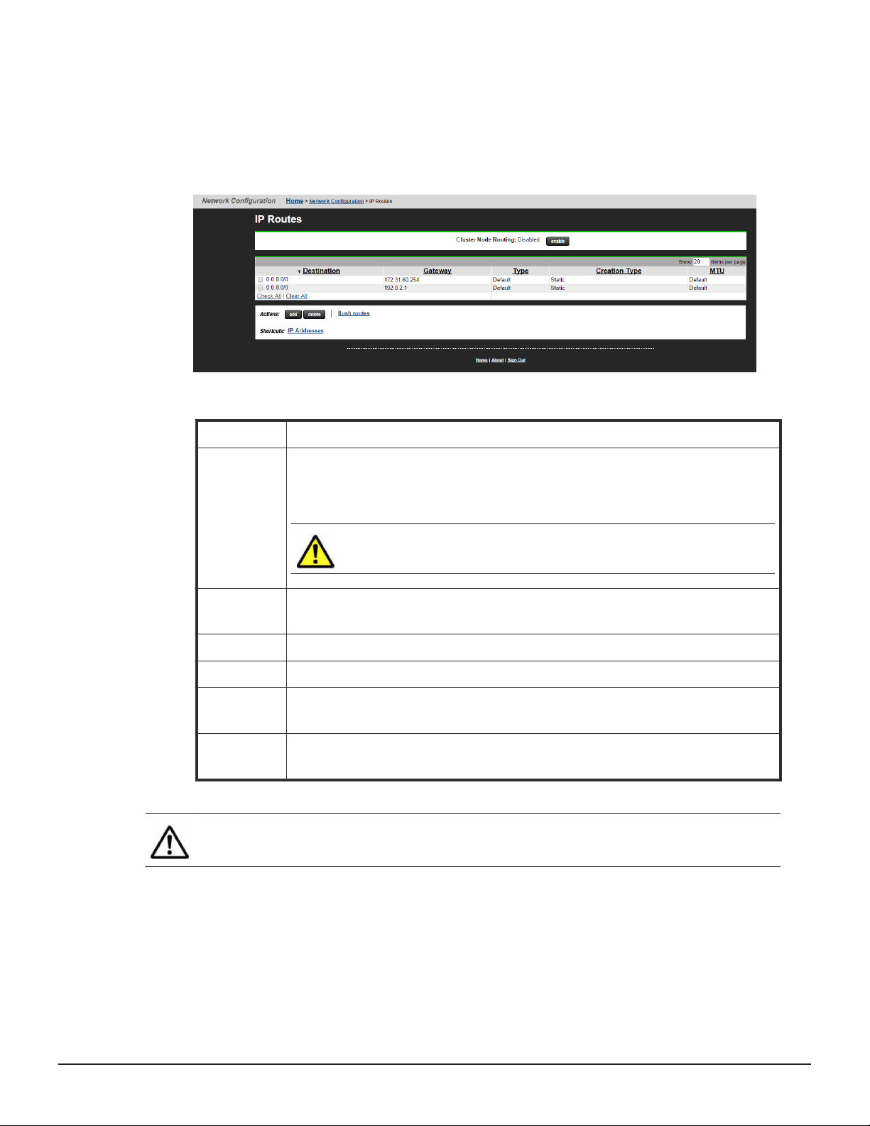
o view the existing IP routes, navigate to Network Configuration > IP
Routes.
The following table describes the fields on this page:
Field / Item Description
Cluster Node
R
outing
Destination For a Network route, this field displays the IP address and Address Prefix Length of
Gateway This field displays the gateway IP address of the route.
Type This field displays the type of route which can be Host, Network, or Gateway.
Creation Type A route is either static or dynamic. Static indicates a manually created route and
MTU This is the Maximum Transmission Unit which is the largest size Ethernet frame that
Note: Fields which are not required for a route t
When this option is disabled (default behavior), the configured routes are
propagated to all nodes in a cluster. If this option is enabled, it is possible to
configure different routes for each node in a cluster.
Caution: If an EVS fails o
route, network traffic can no longer reach the required destination.
the destination. F
dynamic indicates a route created by a switch.
the HNAS server can send for the route.
or a Host route, this field displays an IP address only.
ver to a node which is missing a required
ype are grayed out and
cannot be configured.
Adding IP routes
Hitachi NAS Platform Network Administration Guide
Configuring routes 55
Page 56
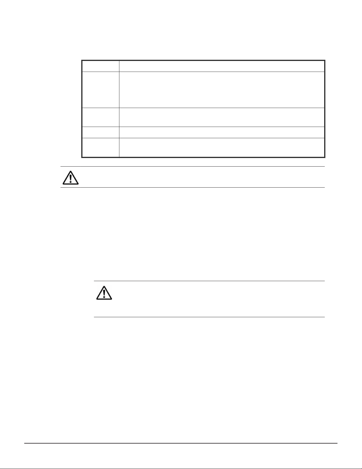
To add an IP route, navigate to Network Configuration > IP Routes and
click the add
button.
The following table describes the fields on this page:
Field / Item Description
Route Type This field requires the type of route which can be Host, Network, or Default
ay). Select the Host option to set an address for a specific computer on a
(Gatew
different network than its usual router address. Select the Network option to set up
a route to address all of the computers on a specific network.
Destination For a Network route, this field requires the IP address and Address Prefix Length of
the destination. F
Gateway This field requires the gateway IP address of the route.
MTU This field requires the Maximum Transmission Unit which is the largest size Ethernet
frame that the HNAS server can send for this route. This is an optional field.
or a Host route, this field requires an IP address only.
Note: Fields which are not required for a route t
cannot be configured.
Deleting IP routes
To delete an IP route
Procedure
1. Na
2. Select the check box next to the route to delete and then click delete.
3. Click OK to confirm the deletion of the IP route.
vigate to Network Configuration > IP Routes.
Note: Dynamic routes cannot be deleted individually
dynamic routes, flush the cache by clicking flush routes. This
operation only applies to the cluster node on which the command
is executed.
To flush other dynamic routes, use the following CLI commands:
•
irdp flush
• ndp-flush
• rip flush
ype are grayed out and
. To delete all
See the CLI Reference for further information.
56 Configuring routes
Hitachi NAS Platform Network Administration Guide
Page 57

Configuring routes 57
Hitachi NAS Platform Network Administration Guide
Page 58

9
Configuring name and directory
services
This section contains information on specif
and configuring NIS and LDAP servers.
Specifying name services
□
Prioritizing name services
□
Configuring NIS servers
□
Configuring LDAP servers
□
ying and prioritizing name services
58 Configuring name and directory services
Hitachi NAS Platform Network Administration Guide
Page 59

Specifying name services
To specify name services
Configuring name and directory services 59
Hitachi NAS Platform Network Administration Guide
Page 60

Procedure
1. Na
vigate to Home > Network Configuration > Name Services to
display the Name Services page.
The following table describes the fields on this page.
Field/Item Description
EVS Security Context Displays the currently selected EVS security context. Changes to
the name services using this page apply only to the currently
selected EVS securit
• If an EVS uses the Global Configuration, any change made to
the global configuration settings affects the EVS.
• If an EVS uses an individual security context, changes made to
the global configuration settings do not affect the EVS. To
change the name services settings of an EVS using an individual
security context, you must select the EVS' individual security
context to make changes, even if those settings are the same as
the settings used by the global security context.
Click change to select a different EVS security context or to
select the global configuration.
DNS Servers Specifies the IP addresses of up to three DNS servers. If more than
one DNS server is entered, the search will be performed using the
DNS servers in the order listed.
DNS Domain Name Specifies the DNS domain name to use.
Domain Search Order Enter a Domain suffix (for example, example.com) to use as a
search keyword.
When searching for a computer name, the DNS server searches
using suffix order. For example, if the server contains the entries
uk.example.com and us.example.com, a request for the IP address
of a host named author generates a query for
y context.
60 Configuring name and directory services
Hitachi NAS Platform Network Administration Guide
Page 61

Field/Item Description
author.uk.example.com and then for author.us.example.com.
er, the system does not search the parent Domain
Howev
example.com.
Note: The suffix, combined with a computer
name, makes up a fully qualified domain name. To append
a suffix to the displayed list, click Add.
To delete a suffix, select it from the displayed list, and
then click X.
When using multiple domain suffixes, select the search
order for the suffixes by using the up and down arrows to
change their order within the list box.
WINS Servers To setup a primary WINS server, enter the IP address in the Primary
WINS serv
If there is a secondary WINS server, enter the address in the
Secondary WINS server field.
apply Save your changes.
er field.
2. Enter the requested information.
3. Click apply to sa
ve your changes.
Note: The new name service appears on the Name Services
Order
page.
’s host
Prioritizing name services
To change the priority of the name services
Procedure
1. Na
2. Use the change button to change the security context, if required.
3. Select and deselect name services to create a list of preferred name
vigate to Network Configuration > Name Services order.
Changes to the name services on this page apply only to the currently
selected EVS security context. If an EVS uses the Global Configuration,
any changes made to the global configuration settings affects the EVS. If
an EVS uses an individual security context, changes made to the global
configuration settings do not affect the EVS. To change the name
services settings of an EVS using an individual security context, you must
select the EVS' individual security context, even if those settings are the
same as the settings used by the global security context.
services. Use the left/right arrow keys to select name services from the
Configuring name and directory services 61
Hitachi NAS Platform Network Administration Guide
Page 62

Available Name Services box and move them to the Selected Name
Services bo
name service back into the Available Name Services box.
4. Adjust the order of usage for selected name services. Use the up/down
arrow keys to change the order of usage for selected name services in
the Selected Name Services box.
5. Click apply to save the changes.
x. To deselect a name service, use the arrows to move the
Configuring NIS servers
Before using NIS, it is necessary to enable NIS for the HNAS server.
To enable NIS, navigate to Network Configuration > NIS/LDAP
Configuration and click Enable NIS.
The current NIS configuration settings appear as shown in the following
example:
This page contains the following options:
• Modify - this option enables the Administr
configuration settings
• Add - this option enables the Administrator to add a new NIS server
ator to change the NIS
62 Configuring name and directory services
Hitachi NAS Platform Network Administration Guide
Page 63

• Delete
- this option enables the Administrator to remove an existing NIS
server
• Switch to using LDAP - this option enables LDAP mode and displays the
LDAP configuration settings
• Disable NIS and LDAP - this option disables NIS and LDAP
CLI commands
The following commands are available:
• nis-ldap-mode - this command selects whether the server uses LDAP or
NIS servers to satisfy NIS queries
• nis-state - this command enables and disables the NIS client
• nis-show - this command displays the current NIS client settings
• nis-set - this command displays and sets the NIS client parameters
• nis-server - this command displays and sets the servers which are
available for the NIS client to contact
Modifying NIS servers
To change the current NIS configuration settings
Procedure
1. Navigate to Network Configuration > NIS/LDAP Configuration.
2. Click modify.
3. Modify the settings as described in the table below.
Field / Item Description
EVS Security
Context
Domain Enter the name of the NIS domain for which the system is a client.
This field displays the currently selected EVS security context. Changes to the
name services on this page apply only to the currently selected EVS securit
context.
If an EVS uses the Global Configuration, any change made to the global
configuration settings affects the EVS. If an EVS uses an individual security
context, changes made to the global configuration settings do not affect the
EVS.
To change the name services settings of an EVS using an individual security
context, you must select the EVS' individual security context, even if those
settings are the same as the settings used by the global security context.
Click change to select a different EVS security context or to select the global
configuration.
y
Rebind This field requires the frequency of the server's attempts to connect to its
configured NIS servers. The default value is 15 minutes.
Configuring name and directory services 63
Hitachi NAS Platform Network Administration Guide
Page 64

Timeout This field requires the amount of time (in milliseconds) to wait for a response
Broadcast For
Servers
4. Click apply.
Adding NIS servers
To add a NIS server
Procedure
from an NIS serv
is 300 milliseconds.
If selected, this field enables the server to discover the available NIS servers
on the network. The servers must be in the same NIS domain and present on
the server’s network.
er when checking the Domain for servers. The default value
1. Na
vigate to Network Configuration > NIS/LDAP Configuration.
2. Click add.
3. Modify the settings as described in the table below.
Field / Item Description
Server IP address Enter the IP address of the new NIS server which can satisfy NIS
queries.
Priority Enter the priority level for the selected NIS server (lowest value is
highest priorit
system attempts to bind to the server with the highest priority level
whenever it performs a rebind check.
The options are:
•
low (3)
• medium (2)
• high (1)
y). If the NIS domain contains multiple servers, the
Note: Serv
If the Administrator assigns a priority after clicking the details
button, the NIS server type becomes “User Defined”. “User
Defined” NIS servers are prioritized before servers discovered
through broadcast.
ers discovered by broadcast do not have a priority.
4. Click OK.
Deleting NIS servers
To delete a NIS server
Procedure
1. Na
2. Select a server to delete.
3. Click delete.
64 Configuring name and directory services
vigate to Network Configuration > NIS/LDAP Configuration.
Hitachi NAS Platform Network Administration Guide
Page 65

Configuring LDAP servers
Before using LDAP
To use LDAP, navigate to Network Configuration > NIS/LDAP
Configuration and click Enable LDAP.
The current LDAP configuration settings appear as shown in the following
example:
, it is necessary to enable LDAP for the HNAS server.
This page contains the following options:
• Modify - this option enables the Administr
configuration settings
• Add - this option enables the Administrator to add a new LDAP server
• Delete - this option enables the Administrator to remove an existing LDAP
server
• Switch to using NIS - this option enables NIS only mode and displays
the NIS configuration settings
• Disable NIS and LDAP - this option disables NIS and LDAP
CLI commands
Configuring name and directory services 65
Hitachi NAS Platform Network Administration Guide
ator to change the LDAP
Page 66

The following commands are available:
• nis-ldap-mode - this command selects whether the serv
servers only or LDAP in order to satisfy NIS queries
• nis-state - this command enables and disables the NIS client (the NIS
client also must be enabled in order to use LDAP)
• ldap-server - this command displays and configures the servers which
are available for the LDAP client to contact
• ldap-stats - this command displays statistics describing the response
latency of LDAP servers for different NIS (RFC 2307) request types
• ldap-security - this command displays and sets the LDAP parameters
• lap-schema - this command displays and sets the LDAP client settings for
schema selection
Modifying LDAP configuration
To change the current LDAP configuration settings
Procedure
1. Navigate to Network Configuration > NIS/LDAP Configuration.
2. Click modify.
3. Modify the settings as described in the table below:
er uses NIS
Field / Item Description
Domain Enter the name of the LDAP domain for which the system is a client.
Username This field contains the username of the Administrator for the LDAP servers.
The name can be up to 256 char
However, if it includes spaces, the name must be enclosed in double quotes.
For example: cn=”Directory Manager”,dc=example,dc=com
Password This field contains the password that corresponds to the username.
TLS Enabled Select this option in order to enable Transport Layer Security which provides
secure communication with the LDAP server.
Schema This field contains the name of the schema to use.
The options are:
• RFC-2307
• MS Services for Unix
• MS Identity Management for Unix
acters in length.
4. Click apply.
Note: This option supports both registered and anon
logins.
ymous user
66 Configuring name and directory services
Hitachi NAS Platform Network Administration Guide
Page 67

Adding LDAP servers
To add an LDAP server
Procedure
1. Na
vigate to Network Configuration > NIS/LDAP Configuration.
2. Click add.
3. Modify the settings as described in the table below.
Field / Item Description
Server IP address or
Host name
Port This field specifies the standard port number to use for communication
TLS Port This field specifies the secure port to use for communication with the
4. Click OK.
Note: An Administr
about hosts configured into netgroups using the nis-is-host-innetgroup and nisnetgroups-for-host commands.
Deleting LDAP servers
Enter the IP address or Host name of the new LDAP server
with the LDAP serv
LDAP server. The default value is 636.
er. The default value is 389.
ator can query the LDAP server for information
To delete an LDAP server
Procedure
1. Na
vigate to Network Configuration > NIS/LDAP Configuration.
2. Select a server to delete.
3. Click delete.
Configuring name and directory services 67
Hitachi NAS Platform Network Administration Guide
Page 68

10
Managing networks and devices
This section contains information on configuring non-file system interfaces
and managing system devices using the SMU
Configuring non-file serving interfaces
□
Configuring devices on the system monitor
□
.
68 Managing networks and devices
Hitachi NAS Platform Network Administration Guide
Page 69

Configuring non-file serving interfaces
On an external SMU only
Procedure
1. Navigate to Home > SMU Administration > Management Network
to display the Management Network page.
2. Enter the requested information. The Management Network page enables
the Administrator to configure the IP address of the eth1 interface. The
default address for the eth1 interface is 192.0.2.1. The eth1 address
must end with . 1, in order to simplify the management relationship of
the SMU with secondary devices. The NAT Port range is provided for
information only.
3. Once defined, record the IP address settings separately for future
reference, and click apply.
, to configure the IP address of the eth1 interface:
Configuring devices on the system monitor
The system monitor allows you to easily display and monitor the devices that
make up your storage system.
Managing networks and devices 69
Hitachi NAS Platform Network Administration Guide
Page 70

Procedure
1. Na
page.
viage to Home > System Monitor to display the System Monitor
2. Optionally
, rearrange the sequence of components in the System
Monitor.
To change the position of any component, fill its checkbox to select, then
use the arrows in the Action section.
3. Optionally, display status or details for any component in the System
Monitor.
The rows in the following table list the basic components that make up a
HNAS system. This table indicates what happens when you click on a
component’s name in the component list:
Component/Description Clicking the component
Storage Server
This component pro
interfaces for connecting to the Public
Data Network and the Private
Management Network, as well as Fibre
Channel interfaces used to connect to
storage subsystems.
vides Ethernet
Loads the Server
Status page.
Clicking the details
button
70 Managing networks and devices
Hitachi NAS Platform Network Administration Guide
Page 71

Component/Description Clicking the component
Clicking the details
button
Main Enclosure
Contains dual power supplies, and dual
RAID driv
model, the main enclosure may contain
disk drives.
Expansion Enclosure
Expansion enclosures contain disk drives
and power supplies, but do not contain
any RAID controllers.
SMU
The System Management Unit
System Power Unit
This component is also known as an
uninterruptible power supply (UPS).
NDMP Backup Devices
The server automatically detects and
adds backup devices to the system
monitor. Since the storage server could
be connected into a FC network shared
with other servers, it does not
automatically make use of backup devices
found on its FC links. Backup devices are
automatically discovered and added to
the Status Monitor.
e controllers. Depending on the
Loads the Enclosure
Status page.
Loads the Enclosure
Status page.
Loads the SMU System
Status page.
Loads the UPS Status
page.
Loads the NDMP
Devices page.
Loads the System
Drives page.
Loads the System
Drives page.
Loads the UPS
Configuration page.
Loads the NDMP
Details page for the
device if the device can
be contacted, or loads
the NDMP Device List
page if the device
cannot be contacted.
FC Switches
FC switches (and cables) connect FC
devices, generally storage arrays, to the
server(s).
Note: Upon adding an FC
switch through the FC S
page, it is automatically added to
the System Monitor.
Other Components
Any component can be added to the
system monitor. If the device supports a
web-based management interface, the
management interface can be launched
directly from the server management
interface.
witches
Loads either the
embedded management
utilit
y for the switch, or
the FC Switch Details
page for the switch,
depending on the
protocol specified when
the switch was added.
For more information,
see the Server and
Cluster Administration
Guide).
Loads the embedded
management utility for
the device.
Loads the FC Switch
Details page.
Loads either the Add
Public Net Device or
the Add Private Net
Device page. Settings
for the component can
Managing networks and devices 71
Hitachi NAS Platform Network Administration Guide
Page 72

Component/Description Clicking the component
Clicking the details
button
be changed from this
page.
4. Optionally
, add, remove, or display details about a device.
The following Actions are available and apply to selected components:
• Click remove to delete a component.
• Click details to display details regarding a particular component.
• Click add Public Net Device to add a device residing on the public
(data) network.
• Click add Private Net Device to add a device residing on the public
(data) network.
Note: Devices on the priv
ate management network are
“hidden” from the data network through Network Address
Translation (NAT).
Once a device has been added to the System Monitor, clicking its name in
the S
ystem Monitor:
• Opens its embedded management utility in the Web browser, using
either HTTP, HTTPS, or Telnet.
• The SMU periodically checks for device activity and connectivity with
the server; if a device fails to respond to network “pings”, the System
Monitor changes its color to red and the SMU issues an alert (devices
can also be configured to send SNMP traps to the SMU).
• Events from the device will be added to the event log if the SMU has a
MIB for the device.
72 Managing networks and devices
Hitachi NAS Platform Network Administration Guide
Page 73

Managing networks and devices 73
Hitachi NAS Platform Network Administration Guide
Page 74

11
Troubleshooting
This section contains information on checking the network status of the
server and also how to detect any potential issues.
Network health information
□
Detecting issues
□
Collecting network packets
□
HNAS
74 Troubleshooting
Hitachi NAS Platform Network Administration Guide
Page 75
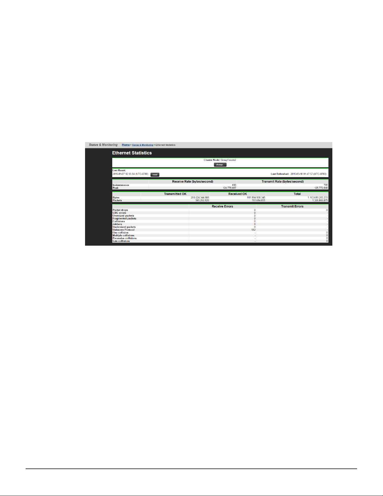
Network health information
The
HNAS server provides information on the current network health status
through the SMU.
Ethernet Statistics
To access this page, navigate to Network Configuration -> Ethernet
Statistics.
This page displays information on transmit and receive rates as well as
throughput, error and collision information as shown below:
There are two additional Ethernet statistics pages:
• Ethernet Statistics (per port) - Aggregation ports - this page
contains network information on a per aggregation basis, for example,
ag1, ag2...
• Ethernet Statistics (per port) - Physical ports - this page contains
network information on a per ph
Navigate to the Network Configuration -> Ethernet Statistics (per port)
page in order to view the Aggregation ports page. On this page, there is a
link to the Ethernet statistics (per port) - Physical ports page.
TCP/IP Statistics
To access this page, navigate to Network Configuration -> TCP/IP
Statistics.
This page displays information on connections, segments, UDP, ICMP and TCP
as shown below:
ysical port basis, for example, tg1, tg2...
Troubleshooting 75
Hitachi NAS Platform Network Administration Guide
Page 76

There are two additional TCP/IP statistics pages:
• TCP/IP Statistics (per port) - Aggregation ports - this page contains
network information on a per aggregation basis, for example, ag1, ag2...
• TCP/IP Statistics (per port) - Physical ports - this page contains
network information on a per ph
ysical port basis, for example, tg1, tg2...
Navigate to the Network Configuration -> TCP/IP Statistics (per port)
page in order to view the Aggregation ports page. On this page, there is a
link to the TCP/IP statistics (per port) - Physical ports page.
Additional commands
The HNAS server also provides the following CLI commands which display
information on the current network health status:
• agg - this command lists any existing aggregations
• ethernetstats - this command displays statistics for each Ethernet
interface
• tcpstats - this command displays statistics for TCP protocol packets
• udpstats - this command displays statistics for UDP protocol packets
• ip-stats-other - this command displays statistics for all other IP protocol
packets
• icmpstats - this command displays statistics for ICMP protocol packets
• icmpv6stats - this command displays statistics for ICMP v6 protocol
packets
• arp - this command displays the IP to MAC address mappings
• ndp-dump - this command displays the IPv6 to MAC address mappings and
also displays any on-link prefixes and discovered routers
76 Troubleshooting
Hitachi NAS Platform Network Administration Guide
Page 77

Detecting issues
The HNA
categorizes and prioritizes problems and then presents the information to the
user through the console.
To activate the diagnosis system, use the trouble command.
This command contains 'groups' which refer to parts of the server and its
storage, for example, there is a Network group and a Storage group. Trouble
also contains 'reporters'. These are individual programs which investigate
issues within the groups.
For example, the Network group contains the following reporters:
CLUSTER-2:$ trouble --list-reporters network
Group Reporter Pri Brd Subject of warnings
----- -------- --- --- -------------------
network aggregation 170 MMB Aggregation status
network network-statistics 180 MMB Network interface statistics
network nim-vlsi 190 MMB NIM VLSIsettings
network network-interfaces 200 MMBNetwork interfaces link status
network remote-nfs 270 MMB RemoteNFS
network nisclient 280 MMB Nisclient status
network wins 290 MMB UnreachableWINS servers
network ip-eng-adv 300 MMB ipeng/ipadv status
network mac-cluster 340 MMB MAC_10status
network mac-network 340 MMB MAC_1status
network external-migration-protocol-errors 350 MMB External
migration protocol errors
network packet-capture 380 MMB Checks that packet-capture is
not running
network remote-http 400 MMB Remote HTTP
S server contains an automatic diagnosis system which identifies,
There are two t
• Fault reporters - these detect issues which can cause degradation of
service.
• Performance reporters - these detect performance values which are out-ofrange (unexpectedly high or low).
This command operates over all cluster nodes unless configured otherwise.
Example of common command usage
The following command reports all issues with the HNAS network group.
trouble network
The report appears as shown in the example below:
ypes of reporters:
Troubleshooting 77
Hitachi NAS Platform Network Administration Guide
Page 78

Collecting network packets
It is possible to perform a complete capture of network pack
server using the packet-capture command. This is useful when the server is
experiencing protocol errors.
Once started, this command collects all header and content packets from the
NAS server and stores them in a file in NAS memory. This file is named tmp
and it can grow to a maximum size of 32MB or 15000 frames (whichever is
reached first).
To retrieve this file, use the nail command to email it to a user. Alternatively,
use the ssget command to send it to the SMU for later collection. The ssget
command works from an ssc connection and, therefore, is usable locally or
on a server connected to an external SMU.
To analyze the file contents, the following filter applications are supported:
• tcpdump
• tshark
• wireshark
The packet-capture command also supports aggregations as shown in the
example below:
ets on a NAS
78 Troubleshooting
Hitachi NAS Platform Network Administration Guide
Page 79

packet-capture --start ag1
Caution: Serv
er performance is severely degraded during packet capture. It
is recommended to use port mirroring on the upstream switch instead of
using the packet capture command on the NAS server.
Troubleshooting 79
Hitachi NAS Platform Network Administration Guide
Page 80

A
VLAN conversion
Previously
VLAN ID and a subnet (using a network address and a subnet mask). It is no
longer possible to create subnet VLANS. This topic describes how to convert
subnet-VLANs to use VLAN interfaces. Seek guidance from your support
provider before attempting the conversion procedure.
The subnet VLANs are maintained by the vlan command. This command
enables the NAS server to display and remove existing subnet VLANs.
However, a script is also available in order to convert legacy subnet-based
VLANs into the new static VLANs. The following procedure describes how to
run the script and convert the VLANs.
The procedure has three stages:
• Accessing the NAS Linux console
• Retrieving and running the script
• Converting a subnet VLAN
Accessing the NAS Linux console
The script does not run under the NAS CLI but is available on the NAS
platform (from version 12.2), through the Linux console.
To access the NAS Linux console:
1. SSH to the SMU IP address
2. Enter q to drop to the operating system prompt of the SMU
3. Enter ssh manager@<cluster node ip>
4. Enter the password, the default is nasadmin
5. Enter exit
6. Enter su
7. Enter the password, the default is nasadmin
, VLANs were configured by defining an association between a
Retrieving and running the script
80 VLAN conversion
Hitachi NAS Platform Network Administration Guide
Page 81
On the NAS Linux console, the script is located at: /opt/mercuryutils/bin/vlan-convert-config.rb.
o obtain the script (from a NAS server named xyz) and copy it onto a local
T
Linux client, enter the following command:
# scp manager@xyz:/opt/mercury-utils/bin/vlan-convert-config.rb .
manager@xyz's password:
vlan-convert-config.rb 00% 23KB 22.9KB/s 00:00
#
Either on the NA
S Linux console or a local Linux client, run the script with the
following parameters:
vlan-convert-config.rb [--user <user>] [--password <password>]
<HNAS-server>
Where:
•
user <user> is the username required to access the server
• password <password> is the password required to access the server
• <hnas-server> is the hostname or address of the NAS server
Note: If the user option is supplied without a corresponding password, the
script prompts for the password without displaying the entered text.
On the NAS Linux console only
When ex
ecuting the script on the NAS Linux console, the name localhost can
be used to identify the NAS server. In this case it is normally not necessary to
supply the username and password.
For example:
/opt/mercury-utils/bin/vlan-convert-config.rb localhost > /tmp/
vlan-conv-commands
Converting a subnet VLAN
The script outputs the commands to run in order to perform the conversion.
Review these changes before applying them to the system by running the
following command:
cat /tmp/vlan-conv-commands
Apply the gener
ated commands to the NAS by running the following
command:
source /tmp/vlan-conv-commands
K
eep a copy of the script output for reference in case a downgrade to a
version of firmware below 12.0 is required, as this information is necessary in
order to convert back.
Example VLAN conversion
□
VLAN conversion 81
Hitachi NAS Platform Network Administration Guide
Page 82

Example VLAN conversion
This example demonstr
ates how to convert subnet-VLANs to use VLAN
interfaces. A sample command and the vlan-conv commands generated by
the script are shown below.
Enter a command as shown in the example below:
manager@hnas(bash):/opt/mercury-utils/bin$ ./vlan-convert-config.rb
localhost > /tmp/vlan-conv-commands
manager@hnas(bash):/opt/mercury-utils/bin$ cat /tmp/vlan-conv-commands
#!/bin/sh
# These are the commands suggested to upgrade the VLAN configuration.
# Running this script will disrupt communications with the HNAS.
# Created for HNAS localhost at 2014-10-14T07:51:46-07:00 [Version
12.2.3750.00].
# Please review this generated script before using it.
# ====================================================
ssc localhost <<SSC-EOS
# Disable any EVS that only contain addresses on a tagged VLAN before
updating the configuration.
echo Disabling any EVS with tagged VLAN prior to re-configuration ...
# Disable EVS 1:HNAS-G3
evs disable -e 1 --confirm
# Remove all addresses in VLANs from still enabled EVS before updating
the configuration.
# This applies to EVS with non-VLAN address assignments in order to
minimise disruption to non-VLAN services.
echo Removing VLAN IP addresses from EVS prior to re-configuration ...
# Remove the address 172.31.61.61/24 on ag1 from EVS 2:evs2
evsipaddr -e 2 --remove --confirm --ip 172.31.61.61
# Remove existing (legacy) VLAN configuration.
vlan remove-all
# Create new VLAN interfaces.
# Processing address 172.31.62.62/24 for ag1-vlan0200.
vlan-interface-create --interface ag1 200
# Processing address 172.31.61.61/24 for ag1-vlan0100.
vlan-interface-create --interface ag1 100
echo Preparing to reconfigure IP addresses on VLANs ...
sleep 5
# Reconfigure IP addresses on VLANs.
# Move address to VLAN interface.
evsipaddr -e 1 --update --confirm --ip 172.31.62.62/24 --port ag1vlan0200
# Restore previously removed address to VLAN interface.
evsipaddr -e 2 --add --ip 172.31.61.61/24 --port ag1-vlan0100
# Enable any EVS that were previously disabled.
echo Enabling the EVS that were previously disabled ...
evs enable -e 1
SSC-EOS
82 VLAN conversion
Hitachi NAS Platform Network Administration Guide
Page 83

After reviewing the vlan-conv
commands, execute the generated file on the
NAS server.
manager@hnas(bash):/tmp$ source ./vlan-convert-commands
HDS NAS OS Console
MAC ID : 34-4E-9E-37-3B-F2
hnas:$
hnas:$ # Disable any EVS that only contain addresses on a tagged
VLAN before updating the configuration.
hnas:$ echo Disabling any EVS with tagged VLAN prior to reconfiguration ...
Disabling any EVS with tagged VLAN prior to re-configuration ...
hnas:$ # Disable EVS 1:HNAS-G3
hnas:$ evs disable -e 1 --confirm
hnas:$
hnas:$ # Remove all addresses in VLANs from still enabled EVS
before updating the configuration.
hnas:$ # This applies to EVS with non-VLAN address assignments
in order to minimise disruption to non-VLAN services.
hnas:$ echo Removing VLAN IP addresses from EVS prior to reconfiguration ...
Removing VLAN IP addresses from EVS prior to re-configuration ...
hnas:$ # Remove the address 172.31.61.61/24 on ag1 from EVS
2:evs2
hnas:$ evsipaddr -e 2 --remove --confirm --ip 172.31.61.61
Warning: Removing IP address 172.31.61.61 while EVS is ONLINE
hnas:$
hnas:$ # Remove existing (legacy) VLAN configuration.
hnas:$ vlan remove-all
hnas:$
hnas:$ # Create new VLAN interfaces.
hnas:$ # Processing address 172.31.62.62/24 for ag1-vlan0200.
hnas:$ vlan-interface-create --interface ag1 200
Created ag1-vlan0200
hnas:$ # Processing address 172.31.61.61/24 for ag1-vlan0100.
hnas:$ vlan-interface-create --interface ag1 100
Created ag1-vlan0100
hnas:$ echo Preparing to reconfigure IP addresses on VLANs ...
Preparing to reconfigure IP addresses on VLANs ...
hnas:$ sleep 5
hnas:$
hnas:$ # Reconfigure IP addresses on VLANs.
hnas:$ # Move address to VLAN interface.
hnas:$ evsipaddr -e 1 --update --confirm --ip 172.31.62.62/24 -port ag1-vlan0200
hnas:$ # Restore previously removed address to VLAN interface.
hnas:$ evsipaddr -e 2 --add --ip 172.31.61.61/24 --port ag1vlan0100
hnas:$
hnas:$ # Enable any EVS that were previously disabled.
hnas:$ echo Enabling the EVS that were previously disabled ...
Enabling the EVS that were previously disabled ...
hnas:$ evs enable -e 1
hnas:$ manager@hnas(bash):/tmp$
VLAN conversion 83
Hitachi NAS Platform Network Administration Guide
Page 84

B
Network ports
This section contains information about the default ports in use for services
on a NA
NAS (listening ports)
Port Protocol IP address type
22 SSH TCP Admin Service node and Cluster node
25 SMTP relay TCP Admin Service node and Cluster node
80 HTTP (SMU GUI) TCP Admin Service node and Cluster node
111 Port mapper TCP/UDP EVS
S server and on an external SMU.
137 NetBIOS name lookup service,
including WINS
139 SMB (CIFS) over NetBIOS TCP EVS
161 SNMP agent UDP Admin Service node, Cluster node and
202 VSS TCP Admin Service node and optionally EVS
206 SSC TCP Admin Service node, Cluster node and
443 HTTPS (SMU GUI) TCP Admin Service node and Cluster node
445 SMB over TCP TCP EVS
762 rquota TCP/UDP EVS
1344 ICAP AV TCP EVS
2049 NFS TCP/UDP EVS
3205 iSNS TCP EVS
3260 iSCSI TCP EVS
4045 lockd TCP/UDP EVS
4048 mountd TCP/UDP EVS
UDP EVS
EVS
optionally EVS
84 Network ports
Hitachi NAS Platform Network Administration Guide
Page 85

4050 statd TCP/UDP EVS
8080 SOAP API (HTTP) TCP Admin Service node and Cluster node
8443 SOAP API (HTTPS) TCP Admin Service node and Cluster node
10000 NDMP TCP EVS
34741 VAAI TCP/UDP EVS
59515 Quorum device communication UDP Cluster node
59535-5
9536
59550 Object replication TCP EVS
Configur
able
Configur
able
Configur
able
Cluster communication UDP Cluster node
NDMP data port TCP EVS
Loopback mountd TCP/UDP Only available on the non-file serving
Loopback NFS TCP/UDP Only available on the non-file serving
NAS as a client
The NA
Port Protocol
25 SMTP TCP
53 DNS TCP/UDP
88 Kerberos TCP/UDP
S server uses these destination ports on a peer server.
interfaces
interfaces
123 NTP UDP
139 SMB (CIFS) over NetBIOS TCP
162 SNMP traps UDP
389 LDAP TCP/UDP
445 SMB over TCP TCP
464 Kerberos Password Change
(kpasswd)
636 LDAP over TLS TCP/UDP
1344 ICAP AV TCP
2049 NFS TCP/UDP
4048 mountd TCP/UDP
59550 Object replication TCP
TCP/UDP
Network ports 85
Hitachi NAS Platform Network Administration Guide
Page 86

Configurable NDMP data port TCP
External SMU (listening ports)
Port Protocol
22 SSH TCP
25 SMTP relay TCP
80 HTTP GUI TCP
123 NTP UDP
162 SNMP trap receiver UDP
443 HTTPS GUI TCP
59515-59536 Quorum device UDP
External SMU as a client
The external SMU uses these destination ports on a peer serv
Port Protocol
25 SMTP relay TCP
123 NTP UDP
8443 SOAP requests to HNAS TCP
2001 HCS device manager updates TCP
er.
86 Network ports
Hitachi NAS Platform Network Administration Guide
Page 87

Network ports 87
Hitachi NAS Platform Network Administration Guide
Page 88

Hitachi NAS Platform Network Administration Guide
Page 89

Hitachi Data Systems
Corporate Headquarters
2845 Lafa
Santa Clara, California 95050-2639
U.S.A.
www.hds.com
Regional Contact Information
Americas
+1 408 970 1000
info@hds.com
Europe, Middle East, and Africa
+44 (0) 1753 618000
info.emea@hds.com
Asia Pacific
+852 3189 7900
hds.marketing.apac@hds.com
yette Street
MK-92HNAS008-08
 Loading...