How it Works
Log In / Sign Up
Buy Points
How it Works
FAQ
Contact Us
Questions and Suggestions
Users
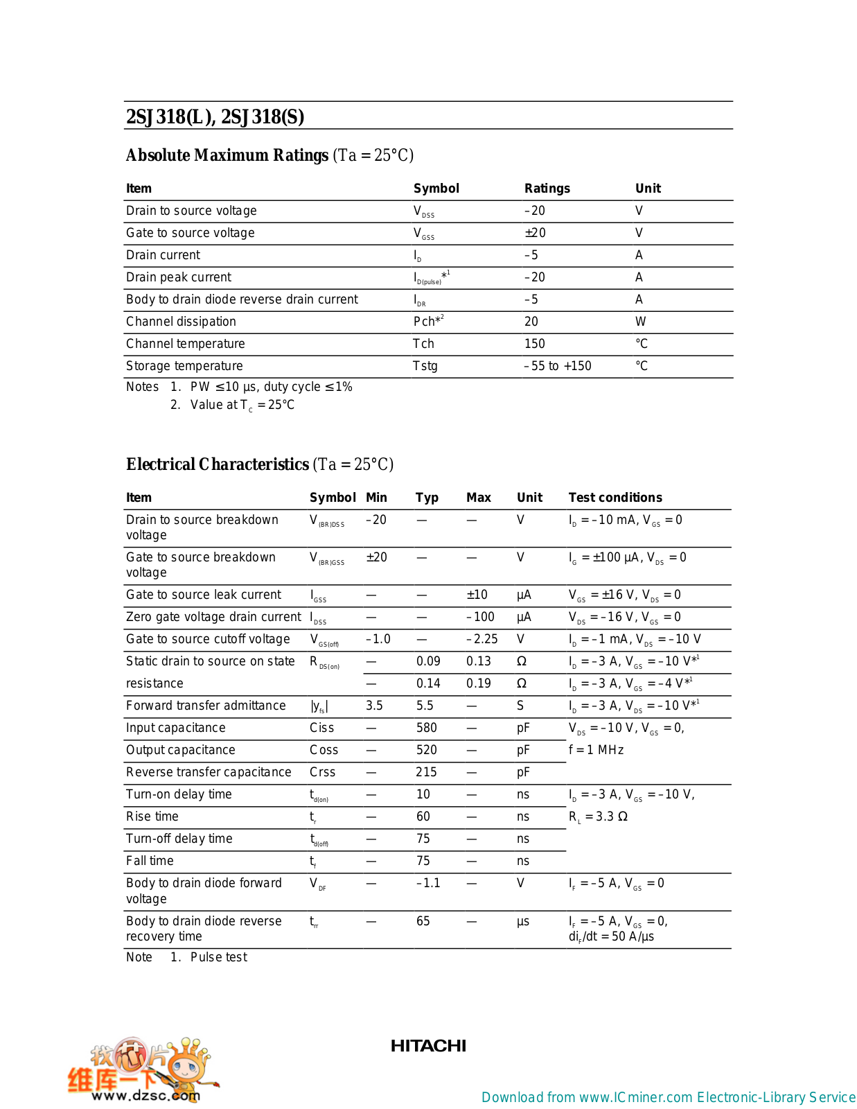
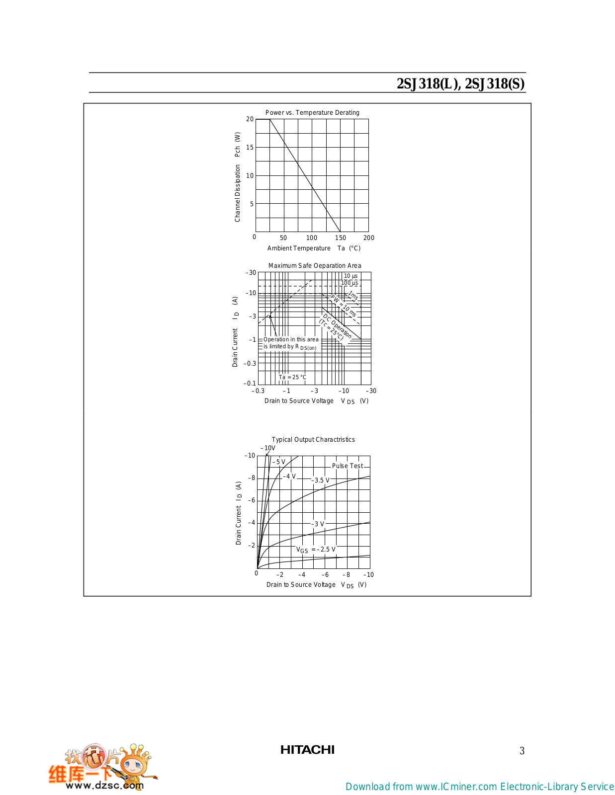
HITACHI
Loading...
#
2SA1083
2
2SA1084
2
2SA1085
2
2SA1121
2SA1122
2SA1171
2SA1188
2SA1189
2SA1190
2
2SA1191
2
2SA1193K
2SA1194K
2
2SA1484
2SB791K
2SC1162
2SC1212
2SC1212A
2SC1213
2SC1213A
2SC1213AK
2SC1342
2SC1344
2SC1345
2SC1345K
2SC3127
2SC3128
2SC3510
2SC3553
2SC4877
2SJ130L
2SJ130S
2SJ160
2SJ161
2SJ162
2SJ172
2SJ174
2SJ175
2SJ176
2SJ177
2SJ217
2SJ218
2SJ220L
2SJ220S
2SJ221
2SJ222
2SJ244
2SJ247
2SJ248
2SJ278
2SJ317
2SJ318-L
2
2SJ318-S
2
2SJ319-L
2SJ319-S
2SK1070
2SK1093
2SK1094
2SK1095
2SK1151-L-S
2SK1152-L-S
2SK1153
2SK1154
2SK1155
2SK1156
2SK1159
2SK1160
2SK1161
2SK1162
2SK1163
2SK1164
2SK1165
2SK1166
2SK1167
2SK1168
2SK1169
2SK1170
2SK1254L
2SK1254S
2SK1296
2SK1298
2SK410
3010E
3080 G1
3080 G2
308996J
3090 G1
3090 G2
311254E
312350E
31CX4B
2
31CX5B
31CX6B
31DX11B
2
31DX21B
3
3000
3080
3090
3100
2
308640
309379
Loading...
Loading...
Nothing found
2SJ318-L
User Manual
7 pgs
271.12 Kb
0
User Manual
8 pgs
91.58 Kb
0
Table of contents
Loading...
HITACHI 2SJ318-L, 2SJ318-S User Manual
...
HITACHI User Manual
Download
Specifications and Main Features
Frequently Asked Questions
User Manual
Download
Page 1
Page 2
Page 3
Page 4
Page 5
Page 6
Page 7
Page 8
Loading...
+
hidden pages
Unhide
You need points to download manuals.
1 point = 1 manual.
You can buy points or you can get point for every manual you upload.
Buy points
Upload your manuals
 Loading...