

HIT HD74HC4543 Datasheet

HD74HC4543
BCD-to-Seven Segment Latch/Decoder/Driver
Description
This circuit contains a 4-bit latch, BCD-to-7 segment decoder, and 7 outpt drivers. Data on the input pins
flow through to the output when the Latch Disable (LE) is high and is latched on the high to low transition
of the LE input. The Phase input (Ph) controls the polarity of the 7 segment outputs. when Ph is low the
outputs are true 7 segment, and when Ph is high the outputs are inverted 7 segment. When the Phase input
is driven by a liquid crystal display (LCD) backplane waveform the segment pins output the correct
segment waveform for proper LCD AC drive voltages.
In addition a Blanking input (BI) is provided, which will blank the display.
Features
• High Speed Operation: tpd (A, B, C, D to a – g) = 33 ns typ (CL = 50 pF)
• High Output Current: Fanout of 10 LSTTL Loads
• Wide Operating Voltage: VCC = 2 to 6 V
• Low Input Current: 1 µA max
• Low Quiescent Supply Current: ICC (static) = 4 µA max (Ta = 25°C)
HD74HC4543
Function Table
Inputs Outputs
1
LD BI Ph*
X H L X X X X L L L L L L L Blank
HLLLLLLHHHHHHL0
HLLLLLHLHHLLLL1
HLLLLHLHHLHHLH2
H L LLL HHHHHHLLH3
HLLLHLLLHHLLHH4
HLLLHLHHLHHLHH5
H L LLHHLHL HHHHH6
H L LLHHHHHHL LLL 7
H L LHL LLHHHHHHH8
H L LHL LHHHHHLHH9
H L L H L H L L L L L L L L Blank
H L L H L H H L L L L L L L Blank
H L L H H L L L L L L L L L Blank
H L L H H L H L L L L L L L Blank
H L L H H H L L L L L L L L Blank
H L L H H H H L L L L L L L Blank
L LLXXXX*
Notes: 1. For liquid crystal readouts, apply a square wave to Ph.
For common cathode LED readouts, select Ph = L. For common anode LED readouts, select
Ph = H
2. Depends upon the BCD coder previously applied when LD = H
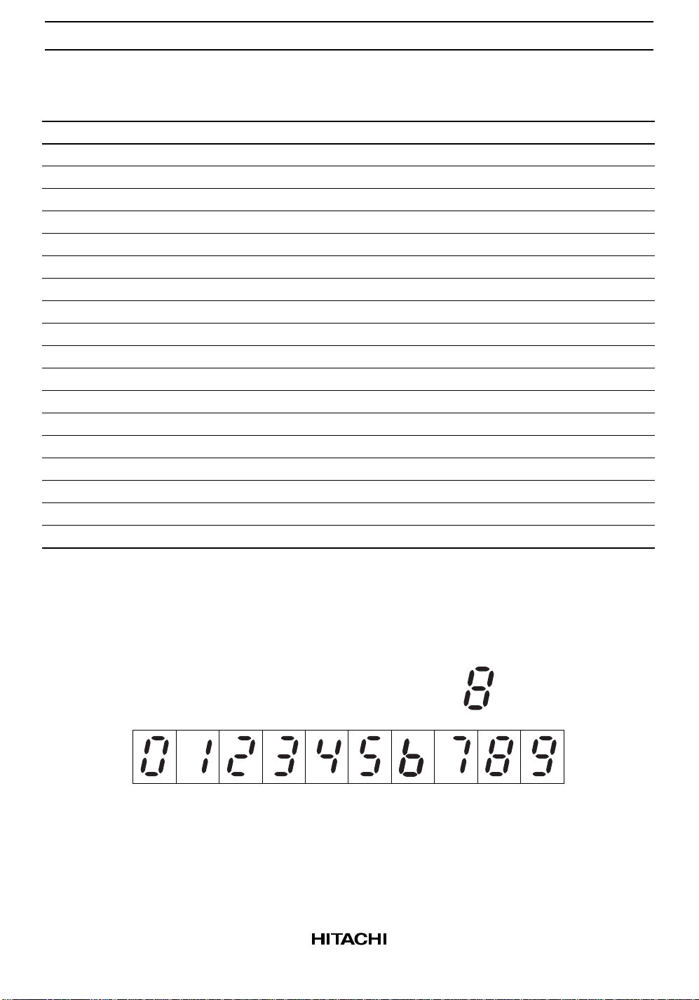
D C B A a b c d e f g Display
2
1
*
a
fg
b
e
c
d
2
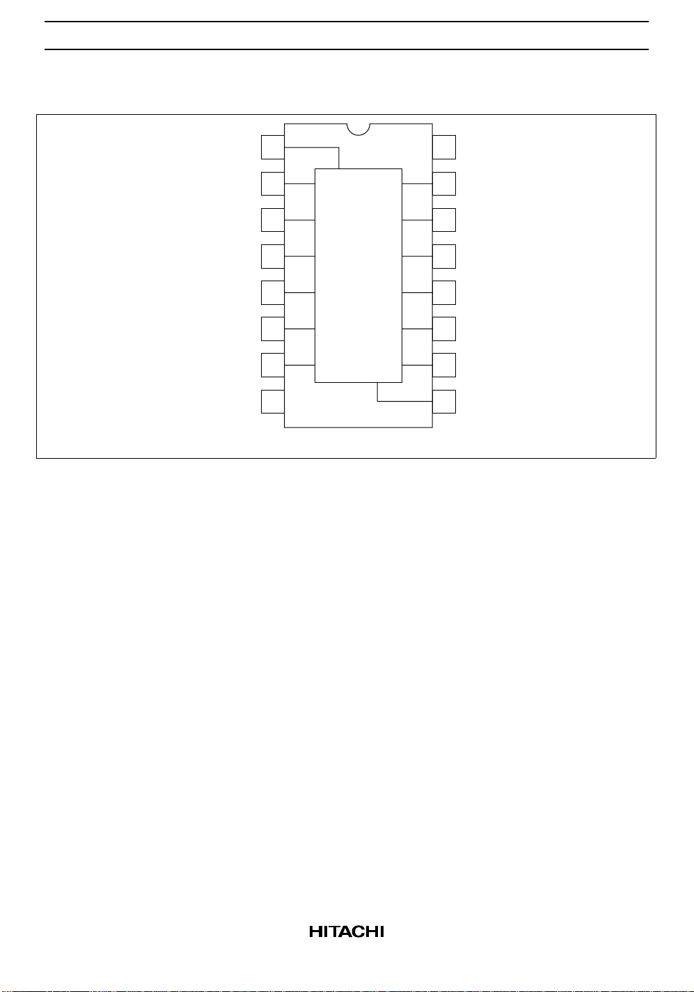
Pin Arrangement
HD74HC4543
Latch
Disable
Phase
Blanking
GND
1
2
C
3
B
4
D
5
A
6
7
8
LD
C
B
D
A
Ph
Bl
(Top view)
f
g
e
d
c
b
a
16
15
14
13
12
11
10
V
CC
f
g
e
d
c
b
a
9
3
 Loading...